EP3590793A2 - Engine cover and work vehicle - Google Patents
Engine cover and work vehicle Download PDFInfo
- Publication number
- EP3590793A2 EP3590793A2 EP19179720.8A EP19179720A EP3590793A2 EP 3590793 A2 EP3590793 A2 EP 3590793A2 EP 19179720 A EP19179720 A EP 19179720A EP 3590793 A2 EP3590793 A2 EP 3590793A2
- Authority
- EP
- European Patent Office
- Prior art keywords
- engine
- exhaust gas
- treatment device
- gas treatment
- work vehicle
- Prior art date
- Legal status (The legal status is an assumption and is not a legal conclusion. Google has not performed a legal analysis and makes no representation as to the accuracy of the status listed.)
- Granted
Links
- 230000002787 reinforcement Effects 0.000 claims abstract description 14
- 230000005540 biological transmission Effects 0.000 claims description 82
- 230000002093 peripheral effect Effects 0.000 claims description 31
- 238000001816 cooling Methods 0.000 claims description 20
- 239000000470 constituent Substances 0.000 claims description 5
- 230000030279 gene silencing Effects 0.000 claims description 4
- 238000003780 insertion Methods 0.000 description 16
- 230000037431 insertion Effects 0.000 description 16
- XLYOFNOQVPJJNP-UHFFFAOYSA-N water Substances O XLYOFNOQVPJJNP-UHFFFAOYSA-N 0.000 description 16
- 239000003921 oil Substances 0.000 description 6
- 238000003892 spreading Methods 0.000 description 6
- 238000003466 welding Methods 0.000 description 6
- 229910000831 Steel Inorganic materials 0.000 description 3
- 238000005452 bending Methods 0.000 description 3
- 230000002706 hydrostatic effect Effects 0.000 description 3
- 238000012423 maintenance Methods 0.000 description 3
- 239000013618 particulate matter Substances 0.000 description 3
- 239000010959 steel Substances 0.000 description 3
- 238000002485 combustion reaction Methods 0.000 description 2
- 230000000694 effects Effects 0.000 description 2
- 238000009313 farming Methods 0.000 description 2
- 239000010720 hydraulic oil Substances 0.000 description 2
- 239000000463 material Substances 0.000 description 2
- 238000000034 method Methods 0.000 description 2
- 238000012545 processing Methods 0.000 description 2
- 230000008929 regeneration Effects 0.000 description 2
- 238000011069 regeneration method Methods 0.000 description 2
- OKTJSMMVPCPJKN-UHFFFAOYSA-N Carbon Chemical compound [C] OKTJSMMVPCPJKN-UHFFFAOYSA-N 0.000 description 1
- 238000009825 accumulation Methods 0.000 description 1
- 238000007664 blowing Methods 0.000 description 1
- 229910052799 carbon Inorganic materials 0.000 description 1
- 238000006073 displacement reaction Methods 0.000 description 1
- 238000010438 heat treatment Methods 0.000 description 1
- 238000009434 installation Methods 0.000 description 1
- 238000003825 pressing Methods 0.000 description 1
- 230000001105 regulatory effect Effects 0.000 description 1
- 238000005728 strengthening Methods 0.000 description 1
- 238000012546 transfer Methods 0.000 description 1
Images


Classifications
-
- F—MECHANICAL ENGINEERING; LIGHTING; HEATING; WEAPONS; BLASTING
- F01—MACHINES OR ENGINES IN GENERAL; ENGINE PLANTS IN GENERAL; STEAM ENGINES
- F01P—COOLING OF MACHINES OR ENGINES IN GENERAL; COOLING OF INTERNAL-COMBUSTION ENGINES
- F01P9/00—Cooling having pertinent characteristics not provided for in, or of interest apart from, groups F01P1/00 - F01P7/00
-
- B—PERFORMING OPERATIONS; TRANSPORTING
- B60—VEHICLES IN GENERAL
- B60K—ARRANGEMENT OR MOUNTING OF PROPULSION UNITS OR OF TRANSMISSIONS IN VEHICLES; ARRANGEMENT OR MOUNTING OF PLURAL DIVERSE PRIME-MOVERS IN VEHICLES; AUXILIARY DRIVES FOR VEHICLES; INSTRUMENTATION OR DASHBOARDS FOR VEHICLES; ARRANGEMENTS IN CONNECTION WITH COOLING, AIR INTAKE, GAS EXHAUST OR FUEL SUPPLY OF PROPULSION UNITS IN VEHICLES
- B60K13/00—Arrangement in connection with combustion air intake or gas exhaust of propulsion units
- B60K13/04—Arrangement in connection with combustion air intake or gas exhaust of propulsion units concerning exhaust
-
- B—PERFORMING OPERATIONS; TRANSPORTING
- B62—LAND VEHICLES FOR TRAVELLING OTHERWISE THAN ON RAILS
- B62D—MOTOR VEHICLES; TRAILERS
- B62D21/00—Understructures, i.e. chassis frame on which a vehicle body may be mounted
- B62D21/18—Understructures, i.e. chassis frame on which a vehicle body may be mounted characterised by the vehicle type and not provided for in groups B62D21/02 - B62D21/17
-
- B—PERFORMING OPERATIONS; TRANSPORTING
- B62—LAND VEHICLES FOR TRAVELLING OTHERWISE THAN ON RAILS
- B62D—MOTOR VEHICLES; TRAILERS
- B62D25/00—Superstructure or monocoque structure sub-units; Parts or details thereof not otherwise provided for
- B62D25/08—Front or rear portions
- B62D25/082—Engine compartments
-
- F—MECHANICAL ENGINEERING; LIGHTING; HEATING; WEAPONS; BLASTING
- F01—MACHINES OR ENGINES IN GENERAL; ENGINE PLANTS IN GENERAL; STEAM ENGINES
- F01N—GAS-FLOW SILENCERS OR EXHAUST APPARATUS FOR MACHINES OR ENGINES IN GENERAL; GAS-FLOW SILENCERS OR EXHAUST APPARATUS FOR INTERNAL COMBUSTION ENGINES
- F01N13/00—Exhaust or silencing apparatus characterised by constructional features ; Exhaust or silencing apparatus, or parts thereof, having pertinent characteristics not provided for in, or of interest apart from, groups F01N1/00 - F01N5/00, F01N9/00, F01N11/00
- F01N13/18—Construction facilitating manufacture, assembly, or disassembly
- F01N13/1805—Fixing exhaust manifolds, exhaust pipes or pipe sections to each other, to engine or to vehicle body
-
- B—PERFORMING OPERATIONS; TRANSPORTING
- B60—VEHICLES IN GENERAL
- B60K—ARRANGEMENT OR MOUNTING OF PROPULSION UNITS OR OF TRANSMISSIONS IN VEHICLES; ARRANGEMENT OR MOUNTING OF PLURAL DIVERSE PRIME-MOVERS IN VEHICLES; AUXILIARY DRIVES FOR VEHICLES; INSTRUMENTATION OR DASHBOARDS FOR VEHICLES; ARRANGEMENTS IN CONNECTION WITH COOLING, AIR INTAKE, GAS EXHAUST OR FUEL SUPPLY OF PROPULSION UNITS IN VEHICLES
- B60K5/00—Arrangement or mounting of internal-combustion or jet-propulsion units
- B60K2005/003—Arrangement or mounting of internal-combustion or jet-propulsion units the internal combustion or jet propulsion unit is arranged between the front and the rear axle
-
- B—PERFORMING OPERATIONS; TRANSPORTING
- B60—VEHICLES IN GENERAL
- B60Y—INDEXING SCHEME RELATING TO ASPECTS CROSS-CUTTING VEHICLE TECHNOLOGY
- B60Y2200/00—Type of vehicle
- B60Y2200/20—Off-Road Vehicles
- B60Y2200/22—Agricultural vehicles
-
- B—PERFORMING OPERATIONS; TRANSPORTING
- B60—VEHICLES IN GENERAL
- B60Y—INDEXING SCHEME RELATING TO ASPECTS CROSS-CUTTING VEHICLE TECHNOLOGY
- B60Y2200/00—Type of vehicle
- B60Y2200/20—Off-Road Vehicles
- B60Y2200/22—Agricultural vehicles
- B60Y2200/221—Tractors
-
- B—PERFORMING OPERATIONS; TRANSPORTING
- B60—VEHICLES IN GENERAL
- B60Y—INDEXING SCHEME RELATING TO ASPECTS CROSS-CUTTING VEHICLE TECHNOLOGY
- B60Y2200/00—Type of vehicle
- B60Y2200/40—Special vehicles
- B60Y2200/41—Construction vehicles, e.g. graders, excavators
-
- E—FIXED CONSTRUCTIONS
- E02—HYDRAULIC ENGINEERING; FOUNDATIONS; SOIL SHIFTING
- E02F—DREDGING; SOIL-SHIFTING
- E02F9/00—Component parts of dredgers or soil-shifting machines, not restricted to one of the kinds covered by groups E02F3/00 - E02F7/00
- E02F9/08—Superstructures; Supports for superstructures
- E02F9/0858—Arrangement of component parts installed on superstructures not otherwise provided for, e.g. electric components, fenders, air-conditioning units
- E02F9/0866—Engine compartment, e.g. heat exchangers, exhaust filters, cooling devices, silencers, mufflers, position of hydraulic pumps in the engine compartment
-
- F—MECHANICAL ENGINEERING; LIGHTING; HEATING; WEAPONS; BLASTING
- F01—MACHINES OR ENGINES IN GENERAL; ENGINE PLANTS IN GENERAL; STEAM ENGINES
- F01N—GAS-FLOW SILENCERS OR EXHAUST APPARATUS FOR MACHINES OR ENGINES IN GENERAL; GAS-FLOW SILENCERS OR EXHAUST APPARATUS FOR INTERNAL COMBUSTION ENGINES
- F01N2340/00—Dimensional characteristics of the exhaust system, e.g. length, diameter or volume of the apparatus; Spatial arrangements of exhaust apparatuses
- F01N2340/04—Dimensional characteristics of the exhaust system, e.g. length, diameter or volume of the apparatus; Spatial arrangements of exhaust apparatuses characterised by the arrangement of an exhaust pipe, manifold or apparatus in relation to vehicle frame or particular vehicle parts
-
- F—MECHANICAL ENGINEERING; LIGHTING; HEATING; WEAPONS; BLASTING
- F01—MACHINES OR ENGINES IN GENERAL; ENGINE PLANTS IN GENERAL; STEAM ENGINES
- F01N—GAS-FLOW SILENCERS OR EXHAUST APPARATUS FOR MACHINES OR ENGINES IN GENERAL; GAS-FLOW SILENCERS OR EXHAUST APPARATUS FOR INTERNAL COMBUSTION ENGINES
- F01N2590/00—Exhaust or silencing apparatus adapted to particular use, e.g. for military applications, airplanes, submarines
- F01N2590/08—Exhaust or silencing apparatus adapted to particular use, e.g. for military applications, airplanes, submarines for heavy duty applications, e.g. trucks, buses, tractors, locomotives
-
- F—MECHANICAL ENGINEERING; LIGHTING; HEATING; WEAPONS; BLASTING
- F01—MACHINES OR ENGINES IN GENERAL; ENGINE PLANTS IN GENERAL; STEAM ENGINES
- F01P—COOLING OF MACHINES OR ENGINES IN GENERAL; COOLING OF INTERNAL-COMBUSTION ENGINES
- F01P2060/00—Cooling circuits using auxiliaries
- F01P2060/16—Outlet manifold
Definitions
- the present invention relates to an engine cover and a work vehicle.
- the present invention has been made in view of the above problems, and it is an object thereof to provide an engine cover capable of appropriately covering the upper side of an engine, and a work vehicle provided with the engine cover.
- the heat shielding plate is provided between the exhaust gas treatment device and the air cleaner, so this configuration is useful for being able to suppress propagation of radiant heat from the exhaust gas treatment device to the air cleaner.
- a dedicated mounting frame for supporting the exhaust gas treatment device is provided, and the heat shielding plate is also provided separately from the mounting frame, there is a problem that the structure of this configuration is likely to become comparatively large.
- the present invention is intended to reduce the influence of heat of the exhaust gas treatment device on other devices, while avoiding an increase in the size of the support structure of the exhaust gas treatment device.
- the engine cover includes a plate member installed above an engine, and the plate member is provided with a reinforcement structure for increasing the torsional rigidity of the plate member.
- the engine cover because the engine cover is provided above the engine, the engine cover can receive plants, water, and the like falling from above. That is, plants or the like that have fallen are unlikely to contact the engine or components in the vicinity of the engine, which are positioned below the engine cover. Also, by providing the reinforcement structure in the plate member that constitutes the engine cover, it is possible to eliminate uniform and significant bending of the entire plate member that constitutes the engine cover when a force is applied to the engine cover.
- an engine cover capable of appropriately covering the upper side of an engine.
- the reinforcement structure has an uneven portion that is at least any one of a recessed portion and a protruding portion that extend linearly and are formed in a surface of the plate member.
- the plate member has a horizontal portion positioned above the engine, and a downward portion extending downward from the horizontal portion, toward the vicinity of a fan belt of a cooling fan provided adjacent to the engine and driven by power of the engine.
- an upward peripheral edge portion having a shape in which the peripheral edge portion is bent upward.
- the upward peripheral edge portion is configured in a shape that contacts another constituent member that is adjacent.
- an engine cover is provided above the engine.
- a work vehicle includes a motive portion having an engine and an exhaust gas treatment device connected to an exhaust manifold of the engine, the exhaust gas treatment device is connected to a fixing portion integrated with the engine through a mounting support, and the mounting support is provided with a mounting portion connectable to the fixing portion, a connecting portion that connects the exhaust gas treatment device, and a heat shielding plate that suppresses conduction of radiant heat between the fixing portion and the exhaust gas treatment device.
- the mounting support of the exhaust gas treatment device is provided with the mounting portion connectable to the fixing portion, and the connecting portion of the exhaust gas treatment device, and is also provided with the heat shielding plate that suppresses conduction of radiant heat between the fixing portion and the exhaust gas treatment device.
- the mounting support itself for supporting the exhaust gas treatment device is provided with the heat shielding plate, it is not necessary to mount a member dedicated to heat shielding separately from the mounting support. Therefore, while reducing the thermal effects of the exhaust gas treatment device on other devices on the fixing portion side, the installation of the exhaust gas treatment device and the structure for performing heat shielding to other devices are made comparatively compact, and there is no need to separately assemble and disassemble a heat shielding member.
- the motive portion is suitable for the motive portion to be provided between a vehicle frame supported by a traveling device, a driving portion disposed to a front side above the vehicle frame, and a loading platform disposed to a rear side of the driving portion above the vehicle frame.
- this configuration by using the heat shielding member, it is not necessary to provide the exhaust gas treatment device at a large distance upward from the fixing portion on the engine side, and the vertical height of the motive portion including the exhaust gas treatment device can easily be formed in a comparatively low height. Therefore, this configuration is easily applied to a vehicle provided with the loading platform on the vehicle frame, and provided with the motive portion whose height in the vertical direction is restricted to a low height.
- the engine is disposed at the front of the motive portion, and a transmission is installed in a continuous manner to the rear of the engine, the exhaust gas treatment device is disposed above the transmission at a position to the rear away from the engine, and the mounting support is attached to the transmission.
- the exhaust gas treatment device is disposed at a position to the rear away from the engine and above the transmission installed in a continuous manner to the rear of the engine. Also, the mounting support is attached to the transmission.
- the exhaust gas treatment device is disposed at a position to the rear away from the engine, heat transmission from the engine to the exhaust gas treatment device is unlikely to occur, and heat transfer from the exhaust gas treatment device to the transmission has little effect on the transmission side because the heat shielding plate is provided in the mounting support.
- the exhaust gas treatment device is disposed such that a longitudinal direction of the exhaust gas treatment device lies along a front-rear direction, a front end portion of the exhaust gas treatment device is connected to the exhaust manifold by an exhaust gas inlet pipe along the front-rear direction, and the bottom of the exhaust gas treatment device is supported by the mounting support in a state where the heat shielding plate faces a lower half side of the exhaust gas treatment device.
- the front end portion of the exhaust gas treatment device disposed such that the longitudinal direction of the exhaust gas treatment device lies along the front-rear direction is connected to the exhaust manifold by the exhaust gas inlet pipe along the front-rear direction, so the position of the exhaust gas treatment device mainly in the front-rear direction due to engine vibration, vehicle sway, or the like is easily restricted using the rigidity of the exhaust gas inlet pipe itself along the front-rear direction. Also, the position of the exhaust gas treatment device in the left-right direction and the vertical direction is restricted by the mounting support that supports the bottom of the exhaust gas treatment device, and therefore the exhaust gas treatment device is reliably supported.
- the exhaust gas treatment device can be supported in a state where the position of the exhaust gas treatment device is reliably regulated in the front, rear, left, right, and vertical directions, without needing to form the mounting support at a corresponding length in the front-rear direction.
- the exhaust gas treatment device is provided with a silencing device.
- FIG. 1 shows an overall side view of the work vehicle.
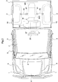
- FIG. 2 shows an overall plan view of the work vehicle.
- a multipurpose work vehicle serving as an example of the work vehicle shown in FIG. 1 , is a work vehicle used for multipurpose applications such as luggage transportation and recreation.
- the work vehicle is provided with a left-right pair of front wheels 1 capable of steering operation, and a left-right pair of rear wheels 2, on a traveling vehicle A.
- a cabin B that constitutes a driving portion is provided at a position toward the front of the traveling vehicle A
- a loading platform 3 is provided at the rear of the traveling vehicle A
- a driving unit C is provided at a position below the loading platform 3.
- this work vehicle is a four-wheel drive type vehicle having a traveling drive system that transmits driving force from the driving unit C to the front wheels 1 and the rear wheels 2, and is configured as a multipurpose work vehicle used for multipurpose work such as farming and transportation.
- a hood 5 is provided at a position toward the front of the traveling vehicle A so as to be capable of opening/closing, and a front fender 6 that covers an upper portion of the front wheels 1 is disposed below left and right portions of the hood 5.
- the cabin B includes a windshield 8 at the front of a cabin body 7, and a door 9 provided so as to be capable of opening/closing from the side of the cabin B.
- a rear fender 18 covering the upper portion of the left and right rear wheels 2 is provided at the rear end side of the traveling vehicle A.
- the cabin B is provided with a driver seat 11 where a driver sits, and a passenger seat (not shown) is provided at a position adjacent to the driver seat 11. Further, a steering wheel 13 or the like that controls steering of the front wheels 1 is provided at a position in front of the driver seat 11.
- an accelerator pedal serving as a speed change controller that controls traveling speed
- a brake pedal that operates a braking device of the front wheels 1 and the rear wheels 2, and the like are also provided at a position in front of the driver seat 11.
- the work vehicle is provided with a vehicle frame F as a strengthening member of the traveling vehicle A.
- the vehicle frame F includes a left-right pair of main frames 21 extending in the front-rear direction, and a left-right pair of upper frames 24 that extend in the front-rear direction of the traveling vehicle A so as to have an attitude parallel to the main frames 21 at a position above a position to the rear of the main frames 21, for example.
- the vehicle frame F is provided with a portion supporting the cabin B at a position in front of the main frames 21, a portion supporting the driving unit C, and the like.
- the main frames 21 and the upper frames 24 are configured using a square pipe-shaped steel material.
- the left and right main frames 21 and the upper frames 24 disposed above the main frames 21 are connected by a connecting frame 28 made of a square pipe-shaped steel material in a vertically directed attitude.
- the driving unit C has a configuration in which an engine E serving as a drive source is connected to a transmission case M.
- the transmission case M is configured to connect a transmission gear case MG and a continuously variable transmission MV.
- a mounting frame 31 is disposed on the lower side (the side below the upper frames 24) of the driving unit C.
- Vertical frames 32 having a U-shaped cross-section are provided, two on the left and right sides respectively, so as to connect the mounting frame 31 to the left and right upper frames 24, and a front frame 33 formed at the front end side of the mounting frame 31 is provided in an attitude directed laterally.
- the mounting frame 31 has a rib-like portion formed by pressing a steel plate or the like to increase strength, and the width of this portion is set to be shorter than the distance between the left and right upper frames 24. Further, in order to linearly connect both ends of the mounting frame 31 and the upper frames 24 by the vertical frames 32, the left and right vertical frames 32 are provided in an inclined attitude displaced toward the outside of the vehicle as much as the upper end side.
- the driving unit C is configured with the engine E, the transmission gear case MG, and the continuously variable transmission MV integrated as a single body, by connecting the engine E, the transmission gear case MG, and the continuously variable transmission MV in this order.
- the transmission gear case MG performs gear shifting of the driving force shifted by the continuously variable transmission MV in multiple steps, and built into the transmission gear case MG there are a gear type transmission that switches between forward and reverse gears, and a differential gear (not shown).
- the continuously variable transmission MV includes, for example, an axial plunger type variable displacement hydraulic pump operated by driving force from the engine E, and an axial plunger type hydraulic motor rotated by hydraulic oil supplied from the hydraulic pump.
- a transmission system is configured in which the engine E is provided in an attitude in which the axis of an output shaft (a crankshaft: not shown) of the engine E is set in the front-rear direction, and a transmission shaft (not shown) that connects to that output shaft passes through the transmission gear case MG in the front-rear direction, so that driving force of the engine E is transmitted to the hydraulic pump of the continuously variable transmission MV, and this driving force from the hydraulic pump of the continuously variable transmission MV is transmitted to the transmission gear case MG.
- the transmission gear case MG the driving force of the engine E is shifted by the transmission and transmitted from the differential gear to left and right rear output shafts 61, and transmitted from the rear output shafts 61 to the left and right rear wheels 2 through a rear wheel drive shaft 62.
- the transmission system is configured such that output of the transmission gear case MG is transmitted from a drive shaft (not shown) to a front wheel differential gear (not shown), and further is transmitted from a front wheel drive shaft (not shown) to the left and right front wheels 1.
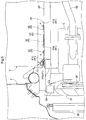
- FIG. 3 shows a plan view illustrating the positional relationship between the engine cover 40 and the engine E.
- FIG. 4 shows a perspective view illustrating the positional relationship between the engine cover 40 and the engine E.
- FIG. 5 shows a partial cross-sectional view illustrating the positional relationship between the engine cover 40 and the engine E.
- Exhaust gas exhausted from the engine E is introduced into a muffler 51 for reducing the exhaust noise of the engine E through an exhaust manifold (not shown) and an exhaust pipe 68.
- the muffler 51 is formed in a cylindrical shape, and is provided with a cylindrical exhaust portion 51A bent at the rear end so as to send the exhaust gas downward on the left side.
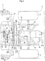
- an oil cooler 36 for cooling hydraulic oil and the like used in the continuously variable transmission MV is provided on the front side of the engine E.
- a cooling fan 37 for blowing air onto the oil cooler 36 to perform cooling is provided between the oil cooler 36 and the engine E.
- the cooling fan 37 is driven by a fan belt 38 rotated by the driving force of the engine E.
- a fan belt cover 39 is provided above and to the sides of the cooling fan 37 and the fan belt 38.
- the engine cover 40 provided above the engine E is provided with a plate member 41 provided above the engine E, and the plate member 41 is provided with a reinforcement structure S for increasing the torsional rigidity of the plate member 41.
- the engine cover 40 is fixed to the upper frames 24 by bolts 4.
- the reinforcement structure S has uneven portions 42 and 43, which are at least any one of a recessed portion and a protruding portion formed extending linearly in the face of the plate member 41.
- the uneven portions 42 and 43 are formed, for example, in a curved shape such as a semicircular cross-section by performing press processing or the like on the plate member 41.
- the reinforcement structure S of the present embodiment is formed in a state in which a plurality of the linearly extending uneven portions 42 and 43 intersect each other at right angles.
- the plate member 41 constituting the engine cover 40 has a horizontal portion 41a positioned above the engine E, and a downward portion 41b extending downward from the horizontal portion 41a, toward the vicinity of the fan belt 38 of the cooling fan 37 provided adjacent to the engine E and driven by the power of the engine E.
- the uneven portions 42 and 43 described above are provided in the horizontal portion 41a of the plate member 41.
- the horizontal portion 41a can receive plants, water, and the like falling from above. As a result, plants or the like that have fallen are unlikely to contact the high temperature engine E, components in the vicinity of the engine E, or the like. In addition, even in a case where the work vehicle is used when it is raining or a case where the work vehicle is used in a location where water or mud gets on the work vehicle, the water or mud is unlikely to get on the engine E, the fan belt 38, or electrical components such as an ignition device installed in the vicinity of the engine E.
- the engine cover 40 can prevent a finger or the like of a person who performs maintenance on the cooling fan 37 and the fan belt 38 from approaching.
- the engine cover 40 is provided with the downward portion 41b, whereby even if a human finger or the like intrudes in the direction of arrow D2 in FIG. 4 , this finger is prevented from approaching the cooling fan 37 and the fan belt 38.
- a finger or the like of a person who performs maintenance on the cooling fan 37 and the fan belt 38 can be prevented from approaching the cooling fan 37 and the fan belt 38 by the downward portion 41b of the engine cover 40.
- this finger is prevented from approaching the cooling fan 37 and the fan belt 38 by the engine cover 40.
- an upward peripheral edge portion 41c having a shape in which the peripheral edge portion is bent upward.
- the peripheral edge portion on the front side (the front side of the work vehicle) of the engine cover 40 is the upward peripheral portion 41c.
- the upward peripheral edge portion 41c of the engine cover 40 of the present embodiment is configured with a shape that contacts another adjacent member (a constituent member 22). Therefore, not only does the peripheral edge portion on the front side of the engine cover 40 serve as the upward peripheral edge portion 41c, but a gap existing on the front side of the engine cover 40 is mostly eliminated. Therefore, it is possible to reliably prevent water from spilling down from the top of the engine cover 40 to the fan belt 38 or the electrical components or the like disposed on the front side.
- a downward peripheral edge portion 41d having a shape in which the peripheral edge portion is bent downward.
- the peripheral edge portion on the rear side (the rear side of the work vehicle) of the engine cover 40 is the downward peripheral edge portion 41d. Therefore, even if water droplets or the like adhere on the engine cover 40, they can selectively drop from the rear side of the engine cover 40.
- the front-rear direction and the left-right direction are described as follows, unless otherwise specified. That is, the traveling direction on the forward side (see arrow F in FIGS. 6 and 7 ) during work travel of the work vehicle to which the present invention is applied is referred to as "front”, and the traveling direction to the backward side (see arrow B in FIGS. 6 and 7 ) is referred to as "rear”.
- the direction corresponding to the right side with reference to the forward attitude in the front-rear direction is referred to as "right”
- the direction similarly corresponding to the left side is referred to as "left”.
- the utility vehicle is provided with a steerable left-right pair of front wheels 201F (corresponding to a traveling device) at the front of a vehicle frame 201 forming a framework of a traveling vehicle.
- a left-right pair of unsteerable rear wheels 201R (corresponding to a traveling device) are supported.
- a driving portion 210 is provided on the upper side of the vehicle frame 201 at the center in the front-rear direction of the traveling vehicle.
- a loading platform 202 is provided on the upper side of the vehicle frame 201 at the rear of the traveling vehicle, and a motive portion 203 is provided at a position below the loading platform 202.
- Driving force from an engine 204 and a transmission 205 provided in a motive portion 203 described later can be transmitted to the front wheels 201F and the rear wheels 201R.
- the utility vehicle is configured as a four-wheel drive vehicle that performs four-wheel drive travel, and is used for multipurpose work such as farming and transportation.
- a ROPS frame 211 that protects the driving portion 210 is provided at a position surrounding the driving portion 210.
- the loading platform 202 has a function of being able to dump a load in a dumping manner by raising the front end side around the horizontal axis in the left-right direction at a position near the rear end of the loading platform 202, and the loading platform 202 is supported by the vehicle frame 201 so as to be capable of swinging around that horizontal axis. Also, a hydraulic actuator (not shown) that raises and lowers the front end side of the loading platform 202 is provided.
- the driving portion 210 is provided with a driver seat 212 where a driver sits, a steering wheel 213 that controls steering of the front wheels 201F, and various operation controllers.
- a passenger seat is disposed adjacent to the driver seat 212.
- an oil cooler (not shown) disposed at a position cooled by a cooling fan 243 of a diesel engine 204 described later, an air passage for introducing outside air to the oil cooler, a battery device (not shown), and the like are disposed.
- the motive portion 203 includes the water-cooled diesel engine 204 (hereinafter simply referred to as the engine) as an internal combustion engine, and the transmission 205 (corresponding to a fixed portion integrated with the engine) fixed to the engine 204.
- a radiator (not shown) for water cooling the engine 204 is disposed inside a front hood 214 at the front of the vehicle.
- the motive portion 203 including the engine 204 and the transmission 205 mentioned above is formed between the vehicle frame 201 and the loading platform 202 disposed on the rear side of the driving portion 210 on the vehicle frame.
- the transmission 205 includes a transmission case 250 in which a gear transmission (not shown) is installed, and a hydrostatic continuously variable transmission 251.
- the transmission case 250 is connected and fixed to the rear of the engine 204, and the hydrostatic continuously variable transmission 251 is connected and fixed to the rear of the transmission case 250.
- the engine 204 is provided with a crankshaft (not shown) along the front-rear direction of the vehicle, and power is transmitted from a front output shaft 241 protruding forward of an engine body 240 through a fan belt 242 to a cooling fan 243 and an alternator 244.
- the cooling fan 243 introduces outside air, and sends out hot air remaining in the oil cooler and in the upper space of the engine 204 positioned to the rear, and also brings the blown outside air into contact with an exhaust gas treatment device 230 described later, thereby performing air cooling.
- Power is transmitted to a traveling system and a work system from an output shaft (not shown) extended rearward from the rear of the engine 204. That is, although not shown, the output from the engine 204 is shifted by the continuously variable transmission 251 as the main transmission in the transmission 205, and further shifted by the gear transmission as an auxiliary transmission, and then power is transmitted to the left and right rear wheels 201R through a rear axle 252 protruding from the transmission case 250 to both left and right sides. Power is transmitted to the front wheels 201F through a transmission shaft 253 extended forward from the lower portion of the transmission case 250.
- the above embodiment is a common embodiment according to the present invention, and below, a support structure of the exhaust gas treatment device 230 will be described in part one and part two of the second embodiment.
- the motive portion 203 is provided with the exhaust gas treatment device 230 that purifies the exhaust gas of the engine 204.
- the exhaust gas treatment device 230 is configured using a diesel particulate filter (DPF) that collects and removes particulate matter mainly containing carbon contained in the exhaust gas.
- DPF diesel particulate filter
- the exhaust gas treatment device 230 is configured to perform a regeneration treatment of heating, burning and removing collected particulate matter in order to prevent a decrease in the collection function caused by the accumulation of collected particulate matter.
- a regeneration treatment of heating, burning and removing collected particulate matter in order to prevent a decrease in the collection function caused by the accumulation of collected particulate matter.
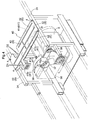
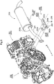
- the exhaust gas treatment device 230 is attached to the transmission 205, which is a fixed portion integrated with the engine 204, through a mounting support 206.
- the mounting support 206 is installed in the upper portion of the transmission case 250 such that the exhaust gas treatment device 230 is positioned to the rear away from the engine 204.
- a front end portion 230a of the exhaust gas treatment device 230 is connected to an exhaust gas inlet pipe 231 in a state mounted to the mounting support 206.
- the front end of the exhaust gas inlet pipe 231 is connected to an exhaust manifold 245 of the engine 204.
- the exhaust gas treatment device 230 is in an attitude in which the longitudinal direction is along the front-rear direction, and the exhaust gas inlet pipe 231 is also disposed in a posture in which the pipe longitudinal direction is substantially along the front-rear direction.
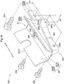
- the mounting support 206 includes a mounting portion 260 that can be bolted to the upper left portion of the transmission case 250, and a connecting portion 261 that is detachable from the mounting portion 260 and is fixed to the exhaust gas treatment device 230.
- the mounting portion 260 includes a bent channel-shaped lower plate 262 whose front and rear end portions protrude laterally outward in plan view, and an upper plate 263 having a flat face portion 263A intersecting the upper end edge of the lower plate 262.
- the flat face portion 263A of the upper plate 263 is fixed by welding to the upper end edge of the lower plate 262.
- the lower plate 262 is provided with a pair of front and rear first bolt insertion holes 262a through which connection bolts 264, screwed into a pair of front and rear lower screw holes 254 formed on the left side face of the transmission case 250, can be inserted.
- the first bolt insertion holes 262a and the lower screw holes 254 are formed at two locations separated by a distance L1 in the front-rear direction.
- a standing piece portion 263B that stands upward is formed at the end closer to the left side face of the transmission case 250.
- a second bolt insertion hole 263a where a connection bolt 264 that is screwed into an upper screw hole 255 formed at a position higher than the lower screw hole 254 formed on the left side face of the transmission case 250 can be inserted, is formed in the standing piece portion 263B.
- the second bolt insertion hole 263a and the upper screw hole 255 are formed at positions higher than the first bolt insertion hole 262a and the lower screw hole 254 by a height H1 in the vertical direction.
- the second bolt insertion hole 263a and the upper screw hole 255 are biased toward the center side in the left-right direction of the transmission case 250 by a horizontal width W1 relative to the first bolt insertion hole 262a and the lower screw hole 254.
- the connecting portion 261 is formed in approximately a V shape, which is provided with a flat portion 261A facing the flat face portion of the mounting portion 260, and at a position facing the lower half side of the cylindrical exhaust gas treatment device 230, an upward spreading inclined plate portion 261B whose width in the left-right direction increases toward the upper side.
- a welding nut 265 provided on the flat plate portion 261A is located at a position facing an elongated connecting hole 263b (see FIGS. 9 and 10 ) having an elongated diameter in the front-rear direction provided on the flat face portion 263A of the mounting portion 260, and is capable of connection or disconnection through a connecting bolt 266 passing through the elongated connecting hole 263b from below.
- An upper end edge 261C of the upward spreading inclined plate portion 261B in the connecting portion 261 is fixed by welding to the lower half side of the cylindrical exhaust gas treatment device 230.
- the connecting portion 261 provided at a position facing the lower half side of the cylindrical exhaust gas treatment device 230 covers the lower half side of the cylindrical exhaust gas treatment device 230, and forms a space S1 where outside air can flow between the outer peripheral face of the exhaust gas treatment device 230 and the outer face of the transmission case 250.
- the flat plate portion 261A of the connecting portion 261 and the upward spreading inclined plate portion 261B fulfill a role as the connecting portion 261 of the mounting support 206, and also function as a heat shielding plate 267 that suppresses conduction of radiant heat between the transmission case 250 and the exhaust gas treatment device 230.
- part two of the second embodiment will be described based on FIGS. 11 to 13 .
- the motive portion 203 is provided with the exhaust gas treatment device 230 in the exhaust gas discharge path of the engine 204.
- the exhaust gas treatment device 230 is configured using a silencing device (a muffler) including a muffling chamber for reducing exhaust noise of exhaust gas.
- the exhaust gas treatment device 230 it is possible to adopt a structure having a muffler, and this same structure can be adopted not only when the engine 204 is a diesel engine, but also when a gasoline engine is used.
- the exhaust gas treatment device 230 is attached to the transmission 205, which is a fixed portion integrated with the engine 204, through the mounting support 206.
- the mounting support 206 is installed in the upper portion of the transmission case 250 such that the exhaust gas treatment device 230 is positioned to the rear away from the engine 204.
- the front end portion 230a of the exhaust gas treatment device 230 is connected to the exhaust gas inlet pipe 231 in a state mounted to the mounting support 206.
- the front end of the exhaust gas inlet pipe 231 is connected to the exhaust manifold 245 of the engine 204.
- the exhaust gas treatment device 230 is in an attitude in which the longitudinal direction is along the front-rear direction, and the exhaust gas inlet pipe 231 is also disposed in a posture in which the pipe longitudinal direction is substantially along the front-rear direction.
- the mounting support 206 includes the mounting portion 260 that can be bolted to the upper left portion of the transmission case 250, and the connecting portion 261 that is detachable from the mounting portion 260 and is fixed to the exhaust gas treatment device 230.
- the mounting portion 260 includes the bent channel-shaped lower plate 262 whose front and rear end portions in a vertical wall portion along the front-rear direction protrude laterally outward in plan view, and the upper plate 263 having the flat face portion 263A intersecting the upper end edge of the lower plate 262.
- the flat face portion 263A of the upper plate 263 is fixed by welding to the upper end edge of the lower plate 262.
- the lower plate 262 is provided with the pair of front and rear first bolt insertion holes 262a through which the connection bolts 264, screwed into the pair of front and rear lower screw holes 254 formed on the left side face of the transmission case 250, can be inserted.
- the first bolt insertion holes 262a and the lower screw holes 254 are formed at two locations separated by the distance L1 in the front-rear direction. In part two of the second embodiment, the distance L in the front-rear direction between the lower screw holes 254 and between the first bolt insertion holes 262a is formed shorter than the distance L1 in the front-rear direction between the first bolt insertion holes 262a in the mounting portion 260 of the structure described in part one of the second embodiment.
- the standing piece portion 263B standing upward is formed at the end closer to the left side face of the transmission case 250.
- the second bolt insertion hole 263a where the connection bolt 264 that is screwed into the upper screw hole 255 formed at a position higher than the lower screw hole 254 formed on the left side face of the transmission case 250 can be inserted, is formed in the standing piece portion 263B.
- the second bolt insertion hole 263a and the upper screw hole 255 are formed at positions higher than the first bolt insertion hole 262a and the lower screw hole 254 by the height H1 in the vertical direction.
- the second bolt insertion hole 263a and the upper screw hole 255 are biased toward the center side in the left-right direction of the transmission case 250 by the horizontal width W1 relative to the first bolt insertion hole 262a and the lower screw hole 254.
- the connecting portion 261 is formed in approximately a V shape, which is provided with the flat portion 261A facing the flat face portion of the mounting portion 260, and at a position facing the lower half side of the cylindrical exhaust gas treatment device 230, the upward spreading inclined plate portion 261B whose width in the left-right direction increases toward the upper side.
- the welding nut 265 provided on the flat plate portion 261A is located at a position facing the elongated connecting hole 263b (see FIG. 12 ) having an elongated diameter in the left-right direction provided on the flat face portion 263A of the mounting portion 260, and is capable of connection or disconnection through the connecting bolt 266 passing through the elongated connecting hole 263b from below.
- the upper end edge 261C of the upward spreading inclined plate portion 261B in the connecting portion 261 is fixed by welding to the lower half side of the cylindrical exhaust gas treatment device 230.
- the connecting portion 261 provided at a position facing the lower half side of the cylindrical exhaust gas treatment device 230 covers the lower half side of the cylindrical exhaust gas treatment device 230, and forms the space S1 where outside air can flow between the outer peripheral face of the exhaust gas treatment device 230 and the outer face of the transmission case 250.
- the flat plate portion 261A of the connecting portion 261 and the upward spreading inclined plate portion 261B fulfill a role as the connecting portion 261 of the mounting support 206, and also function as the heat shielding plate 267 that controls conduction of radiant heat between the transmission case 250 and the exhaust gas treatment device 230.
- the transmission case 250 of the transmission 205 is described as an example of a fixing portion integrated with the engine 204, which is attached to the mounting support 206.
- this is not a limitation of the present invention.
- the hydrostatic continuously variable transmission 251 of the transmission 205, another engine accessory, or the engine 204 itself may be attached to the mounting support 206.
- the mounting support 206 may be configured with the mounting portion 260 and the connecting portion 261 integrated as a single body.
- the mounting support 206 is a structure used with the motive portion 203 provided between the vehicle frame 201, the driving portion 210 disposed to the front side above the vehicle frame 201, and the loading platform 202 disposed to the rear side of the driving portion above the vehicle frame 202.
- the mounting support 206 can also be used at a location where height is not restricted by the loading platform 202, or a location such that the position where the mounting support 206 is disposed is not restricted in the front-rear direction by the driving portion 210.
- a structure provided with the front wheels 201F and the rear wheels 201R is described as an example of a traveling device.
- this is not a limitation of the present invention.
- a crawler traveling device may be adopted instead of any one of the front wheels 201F and the rear wheels 201R, or a crawler traveling device may be adopted instead of both the front wheels 201F and the rear wheels 201R.
- the present invention is not limited to use in utility vehicles, and is also applicable to various work vehicles such as lawn mowers, transport vehicles, agricultural machines, or the like.
Abstract
Description
- The present invention relates to an engine cover and a work vehicle.
-
- (1) Conventionally, there are an engine cover provided above an engine and a work vehicle provided with this engine cover.
Patent Document 1 describes a multipurpose work vehicle used for multipurpose applications such as luggage transportation and recreation. In this multipurpose work vehicle, a loading platform on which luggage is to be placed is installed at the rear. Also, an engine, an exhaust pipe that guides exhaust gas exhausted from the engine, and the like are installed below the loading platform. - (2) Conventionally, there is a work vehicle in which an engine configured using an internal combustion engine, and an exhaust gas treatment device, are disposed in a motive portion.
- As this type of work vehicle, there exists the related art described in [1] below.
- [1] A mounting frame is provided at a position above an engine in an engine room, and the mounting frame supports an exhaust gas treatment device. A heat shielding plate positioned between the exhaust gas treatment device and an air cleaner is provided directed obliquely downward from the mounting frame, and thereby propagation of radiant heat from the exhaust gas treatment device to the air cleaner is suppressed (see Patent Document 2).
-
- Patent Document 1:
JP 2013-43481A - Patent Document 2:
JP 2014-177914A -
- (1) There are problems corresponding to the related art (1) as described below.
- In a work vehicle as described in
Patent Document 1, it is preferable to cover high temperature components, such as the engine installed below the loading platform and an exhaust pipe in the vicinity of the engine, by some method. By adopting such a configuration, even if, for example, plants or the like stacked on the loading platform fall downward, the plants or the like are unlikely to contact the high temperature components. Also, it is preferable to cover the engine, and a fan belt and electrical components such as an ignition device installed in the vicinity of the engine, by some method. By adopting such a configuration, even in a case where the work vehicle is used when it is raining or a case where the work vehicle is used in a location where water or mud gets on the work vehicle, the water or mud is unlikely to get on the fan belt or the electric components. - The present invention has been made in view of the above problems, and it is an object thereof to provide an engine cover capable of appropriately covering the upper side of an engine, and a work vehicle provided with the engine cover.
- (2) There are problems corresponding to the related art (2) as described below.
- In the configuration described in [1] above, the heat shielding plate is provided between the exhaust gas treatment device and the air cleaner, so this configuration is useful for being able to suppress propagation of radiant heat from the exhaust gas treatment device to the air cleaner. However, because a dedicated mounting frame for supporting the exhaust gas treatment device is provided, and the heat shielding plate is also provided separately from the mounting frame, there is a problem that the structure of this configuration is likely to become comparatively large.
- The present invention is intended to reduce the influence of heat of the exhaust gas treatment device on other devices, while avoiding an increase in the size of the support structure of the exhaust gas treatment device.
-
- (1) The Solutions corresponding to the problems in (1) are addressed as described below.
- In a characteristic configuration of an engine cover according to the present invention for achieving the above object, the engine cover includes a plate member installed above an engine, and the plate member is provided with a reinforcement structure for increasing the torsional rigidity of the plate member.
- According to the above characteristic configuration, because the engine cover is provided above the engine, the engine cover can receive plants, water, and the like falling from above. That is, plants or the like that have fallen are unlikely to contact the engine or components in the vicinity of the engine, which are positioned below the engine cover. Also, by providing the reinforcement structure in the plate member that constitutes the engine cover, it is possible to eliminate uniform and significant bending of the entire plate member that constitutes the engine cover when a force is applied to the engine cover.
- Accordingly, it is possible to provide an engine cover capable of appropriately covering the upper side of an engine.
- In another characteristic configuration of an engine cover according to the present invention, the reinforcement structure has an uneven portion that is at least any one of a recessed portion and a protruding portion that extend linearly and are formed in a surface of the plate member.
- According to the above characteristic configuration, by providing the linearly shaped uneven portion formed by press processing or the like in the surface of the plate member, it is possible to eliminate uniform and significant bending of the entire plate member.
- In still another characteristic configuration of an engine cover according to the present invention, the plate member has a horizontal portion positioned above the engine, and a downward portion extending downward from the horizontal portion, toward the vicinity of a fan belt of a cooling fan provided adjacent to the engine and driven by power of the engine.
- According to the above characteristic configuration, with the horizontal portion, it is possible to receive plants, water, and the like that have fallen from above. In addition, with the downward portion, it is possible to prevent a finger or the like of a person who performs maintenance from approaching a fan belt from the vicinity of the engine cover.
- In still another characteristic configuration of an engine cover according to the present invention, at a predetermined location in a peripheral edge portion of the plate member, there is provided an upward peripheral edge portion having a shape in which the peripheral edge portion is bent upward.
- According to the above characteristic configuration, water droplets and the like existing on the plate member are less likely to spill down from the portion where the upward peripheral edge portion is provided. As a result, it is possible a circumstance where water gets on components existing below the engine cover.
- In still another characteristic configuration of an engine cover according to the present invention, the upward peripheral edge portion is configured in a shape that contacts another constituent member that is adjacent.
- According to the above characteristic configuration, it is possible to eliminate the gap between the engine cover and other constituent members adjacent to the engine cover. As a result, water droplets or the like existing on the plate member can be prevented from spilling down from the portion where the upward peripheral edge portion is provided.
- In a characteristic configuration of a work vehicle according to the present invention, an engine cover is provided above the engine.
- According to the above characteristic configuration, it is possible to provide a work vehicle provided with an engine cover capable of appropriately covering the upper side of an engine.
- (2) The Solutions corresponding to the problems in (2) are addressed as described below.
- In order to address the above-described problems, a work vehicle includes a motive portion having an engine and an exhaust gas treatment device connected to an exhaust manifold of the engine, the exhaust gas treatment device is connected to a fixing portion integrated with the engine through a mounting support, and the mounting support is provided with a mounting portion connectable to the fixing portion, a connecting portion that connects the exhaust gas treatment device, and a heat shielding plate that suppresses conduction of radiant heat between the fixing portion and the exhaust gas treatment device.
- According to the present invention, the mounting support of the exhaust gas treatment device is provided with the mounting portion connectable to the fixing portion, and the connecting portion of the exhaust gas treatment device, and is also provided with the heat shielding plate that suppresses conduction of radiant heat between the fixing portion and the exhaust gas treatment device.
- As described above, because the mounting support itself for supporting the exhaust gas treatment device is provided with the heat shielding plate, it is not necessary to mount a member dedicated to heat shielding separately from the mounting support. Therefore, while reducing the thermal effects of the exhaust gas treatment device on other devices on the fixing portion side, the installation of the exhaust gas treatment device and the structure for performing heat shielding to other devices are made comparatively compact, and there is no need to separately assemble and disassemble a heat shielding member.
- Consequently, it is possible to avoid upsizing of the structure for mounting and heat shielding, and to save man-hours for assembly and disassembly.
- In the above configuration, it is suitable for the motive portion to be provided between a vehicle frame supported by a traveling device, a driving portion disposed to a front side above the vehicle frame, and a loading platform disposed to a rear side of the driving portion above the vehicle frame.
- According to this configuration, by using the heat shielding member, it is not necessary to provide the exhaust gas treatment device at a large distance upward from the fixing portion on the engine side, and the vertical height of the motive portion including the exhaust gas treatment device can easily be formed in a comparatively low height. Therefore, this configuration is easily applied to a vehicle provided with the loading platform on the vehicle frame, and provided with the motive portion whose height in the vertical direction is restricted to a low height.
- In the above configuration, it is suitable that the engine is disposed at the front of the motive portion, and a transmission is installed in a continuous manner to the rear of the engine, the exhaust gas treatment device is disposed above the transmission at a position to the rear away from the engine, and the mounting support is attached to the transmission.
- According to this configuration, the exhaust gas treatment device is disposed at a position to the rear away from the engine and above the transmission installed in a continuous manner to the rear of the engine. Also, the mounting support is attached to the transmission.
- Thus, because the exhaust gas treatment device is disposed at a position to the rear away from the engine, heat transmission from the engine to the exhaust gas treatment device is unlikely to occur, and heat transfer from the exhaust gas treatment device to the transmission has little effect on the transmission side because the heat shielding plate is provided in the mounting support.
- In the above configuration, it is suitable that the exhaust gas treatment device is disposed such that a longitudinal direction of the exhaust gas treatment device lies along a front-rear direction, a front end portion of the exhaust gas treatment device is connected to the exhaust manifold by an exhaust gas inlet pipe along the front-rear direction, and the bottom of the exhaust gas treatment device is supported by the mounting support in a state where the heat shielding plate faces a lower half side of the exhaust gas treatment device.
- According to this configuration, the front end portion of the exhaust gas treatment device disposed such that the longitudinal direction of the exhaust gas treatment device lies along the front-rear direction is connected to the exhaust manifold by the exhaust gas inlet pipe along the front-rear direction, so the position of the exhaust gas treatment device mainly in the front-rear direction due to engine vibration, vehicle sway, or the like is easily restricted using the rigidity of the exhaust gas inlet pipe itself along the front-rear direction. Also, the position of the exhaust gas treatment device in the left-right direction and the vertical direction is restricted by the mounting support that supports the bottom of the exhaust gas treatment device, and therefore the exhaust gas treatment device is reliably supported.
- As a result, even if the exhaust gas treatment device is comparatively long, the exhaust gas treatment device can be supported in a state where the position of the exhaust gas treatment device is reliably regulated in the front, rear, left, right, and vertical directions, without needing to form the mounting support at a corresponding length in the front-rear direction.
- In the above configuration, it is suitable that the exhaust gas treatment device is provided with a silencing device.
- According to this configuration, it is possible to support an exhaust gas treatment device provided with a silencing device.
-
-
FIG. 1 shows a first embodiment (the same below throughFIG. 5 ), and is an overall side view of a work vehicle. -
FIG. 2 shows an overall plan view of the work vehicle. -
FIG. 3 shows a plan view illustrating the positional relationship between an engine cover and an engine. -
FIG. 4 shows a perspective view illustrating the positional relationship between the engine cover and the engine. -
FIG. 5 shows a partial cross-sectional view illustrating the positional relationship between the engine cover and the engine. -
FIG. 6 shows a second embodiment (the same below throughFIG. 13 ), and is a left side view of a utility vehicle in which the present invention is applied. -
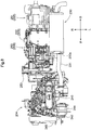
FIG. 7 shows a left side view showing an engine, a transmission and an exhaust gas treatment device in a motive portion of part one of the second embodiment. -
FIG. 8 shows a plan view showing the engine, the transmission and the exhaust gas treatment device in the motive portion of part one of the second embodiment. -
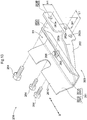
FIG. 9 shows an exploded perspective view showing the transmission and the exhaust gas treatment device in the motive portion of part one of the second embodiment. -
FIG. 10 shows a perspective view showing a mounting support of part one of the second embodiment. -
FIG. 11 shows a left side view showing the engine, the transmission and the exhaust gas treatment device in the motive portion of part two of the second embodiment. -
FIG. 12 shows an exploded perspective view showing the transmission and the exhaust gas treatment device in the motive portion of part two of the second embodiment. -
FIG. 13 shows a perspective view showing a mounting support of part two of the second embodiment. - A work vehicle provided with an
engine cover 40 according to an embodiment of the present invention will be described below with reference to the drawings. -
FIG. 1 shows an overall side view of the work vehicle.FIG. 2 shows an overall plan view of the work vehicle. A multipurpose work vehicle, serving as an example of the work vehicle shown inFIG. 1 , is a work vehicle used for multipurpose applications such as luggage transportation and recreation. As shown, the work vehicle is provided with a left-right pair offront wheels 1 capable of steering operation, and a left-right pair ofrear wheels 2, on a traveling vehicle A. In addition, a cabin B that constitutes a driving portion is provided at a position toward the front of the traveling vehicle A, aloading platform 3 is provided at the rear of the traveling vehicle A, and a driving unit C is provided at a position below theloading platform 3. - For example, this work vehicle is a four-wheel drive type vehicle having a traveling drive system that transmits driving force from the driving unit C to the
front wheels 1 and therear wheels 2, and is configured as a multipurpose work vehicle used for multipurpose work such as farming and transportation. - A
hood 5 is provided at a position toward the front of the traveling vehicle A so as to be capable of opening/closing, and afront fender 6 that covers an upper portion of thefront wheels 1 is disposed below left and right portions of thehood 5. The cabin B includes awindshield 8 at the front of acabin body 7, and adoor 9 provided so as to be capable of opening/closing from the side of the cabin B. - A
rear fender 18 covering the upper portion of the left and rightrear wheels 2 is provided at the rear end side of the traveling vehicle A. - The cabin B is provided with a
driver seat 11 where a driver sits, and a passenger seat (not shown) is provided at a position adjacent to thedriver seat 11. Further, asteering wheel 13 or the like that controls steering of thefront wheels 1 is provided at a position in front of thedriver seat 11. Although not shown, an accelerator pedal serving as a speed change controller that controls traveling speed, a brake pedal that operates a braking device of thefront wheels 1 and therear wheels 2, and the like are also provided at a position in front of thedriver seat 11. - The work vehicle is provided with a vehicle frame F as a strengthening member of the traveling vehicle A. The vehicle frame F includes a left-right pair of
main frames 21 extending in the front-rear direction, and a left-right pair ofupper frames 24 that extend in the front-rear direction of the traveling vehicle A so as to have an attitude parallel to themain frames 21 at a position above a position to the rear of themain frames 21, for example. Also, the vehicle frame F is provided with a portion supporting the cabin B at a position in front of themain frames 21, a portion supporting the driving unit C, and the like. For example, themain frames 21 and theupper frames 24 are configured using a square pipe-shaped steel material. The left and rightmain frames 21 and theupper frames 24 disposed above themain frames 21 are connected by a connectingframe 28 made of a square pipe-shaped steel material in a vertically directed attitude. - In the present embodiment, the driving unit C has a configuration in which an engine E serving as a drive source is connected to a transmission case M. The transmission case M is configured to connect a transmission gear case MG and a continuously variable transmission MV. A mounting
frame 31 is disposed on the lower side (the side below the upper frames 24) of the driving unit C. Vertical frames 32 having a U-shaped cross-section are provided, two on the left and right sides respectively, so as to connect the mountingframe 31 to the left and rightupper frames 24, and afront frame 33 formed at the front end side of the mountingframe 31 is provided in an attitude directed laterally. - The mounting
frame 31 has a rib-like portion formed by pressing a steel plate or the like to increase strength, and the width of this portion is set to be shorter than the distance between the left and right upper frames 24. Further, in order to linearly connect both ends of the mountingframe 31 and theupper frames 24 by thevertical frames 32, the left and rightvertical frames 32 are provided in an inclined attitude displaced toward the outside of the vehicle as much as the upper end side. - In the present embodiment, the driving unit C is configured with the engine E, the transmission gear case MG, and the continuously variable transmission MV integrated as a single body, by connecting the engine E, the transmission gear case MG, and the continuously variable transmission MV in this order.
- Although the internal structure of the transmission gear case MG is not shown in the drawings, the transmission gear case MG performs gear shifting of the driving force shifted by the continuously variable transmission MV in multiple steps, and built into the transmission gear case MG there are a gear type transmission that switches between forward and reverse gears, and a differential gear (not shown).
- The continuously variable transmission MV includes, for example, an axial plunger type variable displacement hydraulic pump operated by driving force from the engine E, and an axial plunger type hydraulic motor rotated by hydraulic oil supplied from the hydraulic pump. In this driving unit C, a transmission system is configured in which the engine E is provided in an attitude in which the axis of an output shaft (a crankshaft: not shown) of the engine E is set in the front-rear direction, and a transmission shaft (not shown) that connects to that output shaft passes through the transmission gear case MG in the front-rear direction, so that driving force of the engine E is transmitted to the hydraulic pump of the continuously variable transmission MV, and this driving force from the hydraulic pump of the continuously variable transmission MV is transmitted to the transmission gear case MG.
- In the transmission gear case MG, the driving force of the engine E is shifted by the transmission and transmitted from the differential gear to left and right
rear output shafts 61, and transmitted from therear output shafts 61 to the left and rightrear wheels 2 through a rearwheel drive shaft 62. Also, the transmission system is configured such that output of the transmission gear case MG is transmitted from a drive shaft (not shown) to a front wheel differential gear (not shown), and further is transmitted from a front wheel drive shaft (not shown) to the left and rightfront wheels 1. - The
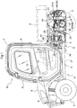
engine cover 40 is provided above the engine E.FIG. 3 shows a plan view illustrating the positional relationship between theengine cover 40 and the engine E.FIG. 4 shows a perspective view illustrating the positional relationship between theengine cover 40 and the engine E.FIG. 5 shows a partial cross-sectional view illustrating the positional relationship between theengine cover 40 and the engine E. Exhaust gas exhausted from the engine E is introduced into amuffler 51 for reducing the exhaust noise of the engine E through an exhaust manifold (not shown) and anexhaust pipe 68. Themuffler 51 is formed in a cylindrical shape, and is provided with acylindrical exhaust portion 51A bent at the rear end so as to send the exhaust gas downward on the left side. - As shown in
FIG. 2 and the like, an oil cooler 36 for cooling hydraulic oil and the like used in the continuously variable transmission MV is provided on the front side of the engine E. A coolingfan 37 for blowing air onto theoil cooler 36 to perform cooling is provided between theoil cooler 36 and the engine E. The coolingfan 37 is driven by afan belt 38 rotated by the driving force of the engine E. Afan belt cover 39 is provided above and to the sides of the coolingfan 37 and thefan belt 38. - The
engine cover 40 provided above the engine E is provided with aplate member 41 provided above the engine E, and theplate member 41 is provided with a reinforcement structure S for increasing the torsional rigidity of theplate member 41. Theengine cover 40 is fixed to theupper frames 24 bybolts 4. - The reinforcement structure S has
uneven portions plate member 41. Theuneven portions plate member 41. In particular, the reinforcement structure S of the present embodiment is formed in a state in which a plurality of the linearly extendinguneven portions uneven portions entire plate member 41 that constitutes theengine cover 40 when a force is applied to theengine cover 40. - The
plate member 41 constituting theengine cover 40 has ahorizontal portion 41a positioned above the engine E, and adownward portion 41b extending downward from thehorizontal portion 41a, toward the vicinity of thefan belt 38 of the coolingfan 37 provided adjacent to the engine E and driven by the power of the engine E. Theuneven portions horizontal portion 41a of theplate member 41. - By adopting such a configuration, the
horizontal portion 41a can receive plants, water, and the like falling from above. As a result, plants or the like that have fallen are unlikely to contact the high temperature engine E, components in the vicinity of the engine E, or the like. In addition, even in a case where the work vehicle is used when it is raining or a case where the work vehicle is used in a location where water or mud gets on the work vehicle, the water or mud is unlikely to get on the engine E, thefan belt 38, or electrical components such as an ignition device installed in the vicinity of the engine E. - In the present embodiment, the
engine cover 40 can prevent a finger or the like of a person who performs maintenance on the coolingfan 37 and thefan belt 38 from approaching. For example, theengine cover 40 is provided with thedownward portion 41b, whereby even if a human finger or the like intrudes in the direction of arrow D2 inFIG. 4 , this finger is prevented from approaching the coolingfan 37 and thefan belt 38. In particular, even if a hole or the like is provided in thefan belt cover 39 provided above and to the sides of the coolingfan 37 and thefan belt 38, a finger or the like of a person who performs maintenance on the coolingfan 37 and thefan belt 38 can be prevented from approaching the coolingfan 37 and thefan belt 38 by thedownward portion 41b of theengine cover 40. Also, even if a human finger or the like intrudes in the direction of arrow D1 inFIG. 4 , this finger is prevented from approaching the coolingfan 37 and thefan belt 38 by theengine cover 40. - At a predetermined location in the peripheral edge portion of the
plate member 41 of theengine cover 40, there is provided an upwardperipheral edge portion 41c having a shape in which the peripheral edge portion is bent upward. In the present embodiment, the peripheral edge portion on the front side (the front side of the work vehicle) of theengine cover 40 is the upwardperipheral portion 41c. By providing such an upwardperipheral edge 41c on theengine cover 40, even if water or the like adheres to the top of theengine cover 40, this water is unlikely to spill down from the front side peripheral edge portion (the upwardperipheral edge portion 41c). As a result, the water does not spill down toward thefan belt 38 or the electrical components or the like disposed on the front side of theengine cover 40. In particular, as shown inFIG. 5 , the upwardperipheral edge portion 41c of theengine cover 40 of the present embodiment is configured with a shape that contacts another adjacent member (a constituent member 22). Therefore, not only does the peripheral edge portion on the front side of theengine cover 40 serve as the upwardperipheral edge portion 41c, but a gap existing on the front side of theengine cover 40 is mostly eliminated. Therefore, it is possible to reliably prevent water from spilling down from the top of theengine cover 40 to thefan belt 38 or the electrical components or the like disposed on the front side. - In addition, at a predetermined location in the peripheral edge portion of the
plate member 41 of theengine cover 40, there is provided a downwardperipheral edge portion 41d having a shape in which the peripheral edge portion is bent downward. In the present embodiment, the peripheral edge portion on the rear side (the rear side of the work vehicle) of theengine cover 40 is the downwardperipheral edge portion 41d. Therefore, even if water droplets or the like adhere on theengine cover 40, they can selectively drop from the rear side of theengine cover 40. -
- 1. In the above embodiment, the
engine cover 40 and the work vehicle provided therewith according to the present invention are described as an example, but their configurations can be appropriately modified.
For example, the size, shape, or the like of theengine cover 40 can be appropriately modified according to the size or the like of the engine E, other members, or the like.
Also, the number, length, cross-sectional shape, or the like of the linearuneven portions plate member 41 constituting theengine cover 40 can be appropriately modified.
In addition, in the above embodiment, an example is described in which the reinforcement structure S is formed in a state in which a plurality of the linearly extendinguneven portions
Also, in the reinforcement structure S, a configuration may be adopted in which rigidity of theplate member 41 is not increased by theuneven portions plate member 41 itself as described in the above embodiment, but rather, rigidity of theplate member 41 is increased by fixing a long member separate from theplate member 41 to theplate member 41, for example. - 2. In the above embodiment, a multipurpose work vehicle is described as an example of a work vehicle, but the present invention can be applied to various types of work vehicles equipped with an engine E, and is not limited to a multipurpose work vehicle.
- 3. The configurations disclosed in the above embodiments (including the other embodiments, the same applies hereinafter) can be applied in combination with a configuration disclosed in another embodiment as long as there is no contradiction. Furthermore, the embodiments disclosed in the present specification are merely examples. The embodiments of the present invention are not limited by these examples, and can be appropriately modified within a range that does not depart from the object of the present invention.
- 4. The present invention can be used for an engine cover that can appropriately cover the upper portion of an engine and a work vehicle provided with this engine cover.
- Exemplary embodiments of a work vehicle according to the present invention will be described below with reference to the drawings.
- In the description of the present embodiment, the front-rear direction and the left-right direction are described as follows, unless otherwise specified. That is, the traveling direction on the forward side (see arrow F in
FIGS. 6 and7 ) during work travel of the work vehicle to which the present invention is applied is referred to as "front", and the traveling direction to the backward side (see arrow B inFIGS. 6 and7 ) is referred to as "rear". The direction corresponding to the right side with reference to the forward attitude in the front-rear direction (see arrow R inFIG. 8 ) is referred to as "right", and the direction similarly corresponding to the left side (see arrow L inFIG. 8 ) is referred to as "left". - Here, a case will be described where the present invention is applied to a utility vehicle (corresponding to a multipurpose vehicle) serving as an example of a work vehicle.
- As shown in
FIGS. 6 and7 , the utility vehicle is provided with a steerable left-right pair offront wheels 201F (corresponding to a traveling device) at the front of avehicle frame 201 forming a framework of a traveling vehicle. At the rear of thevehicle frame 201, a left-right pair of unsteerablerear wheels 201R (corresponding to a traveling device) are supported. - A driving
portion 210 is provided on the upper side of thevehicle frame 201 at the center in the front-rear direction of the traveling vehicle. Aloading platform 202 is provided on the upper side of thevehicle frame 201 at the rear of the traveling vehicle, and amotive portion 203 is provided at a position below theloading platform 202. - Driving force from an
engine 204 and atransmission 205 provided in amotive portion 203 described later can be transmitted to thefront wheels 201F and therear wheels 201R. As a result, the utility vehicle is configured as a four-wheel drive vehicle that performs four-wheel drive travel, and is used for multipurpose work such as farming and transportation. AROPS frame 211 that protects the drivingportion 210 is provided at a position surrounding the drivingportion 210. - The
loading platform 202 has a function of being able to dump a load in a dumping manner by raising the front end side around the horizontal axis in the left-right direction at a position near the rear end of theloading platform 202, and theloading platform 202 is supported by thevehicle frame 201 so as to be capable of swinging around that horizontal axis. Also, a hydraulic actuator (not shown) that raises and lowers the front end side of theloading platform 202 is provided. - The driving
portion 210 is provided with adriver seat 212 where a driver sits, asteering wheel 213 that controls steering of thefront wheels 201F, and various operation controllers. - A passenger seat is disposed adjacent to the
driver seat 212. In the space under the seat corresponding to the lower side of thedriver seat 212, an oil cooler (not shown) disposed at a position cooled by a coolingfan 243 of adiesel engine 204 described later, an air passage for introducing outside air to the oil cooler, a battery device (not shown), and the like are disposed. - As shown in
FIGS. 7 to 9 , themotive portion 203 includes the water-cooled diesel engine 204 (hereinafter simply referred to as the engine) as an internal combustion engine, and the transmission 205 (corresponding to a fixed portion integrated with the engine) fixed to theengine 204. A radiator (not shown) for water cooling theengine 204 is disposed inside afront hood 214 at the front of the vehicle. - The
motive portion 203 including theengine 204 and thetransmission 205 mentioned above is formed between thevehicle frame 201 and theloading platform 202 disposed on the rear side of the drivingportion 210 on the vehicle frame. - The
transmission 205 includes atransmission case 250 in which a gear transmission (not shown) is installed, and a hydrostatic continuouslyvariable transmission 251. Thetransmission case 250 is connected and fixed to the rear of theengine 204, and the hydrostatic continuouslyvariable transmission 251 is connected and fixed to the rear of thetransmission case 250. - The
engine 204 is provided with a crankshaft (not shown) along the front-rear direction of the vehicle, and power is transmitted from afront output shaft 241 protruding forward of anengine body 240 through afan belt 242 to a coolingfan 243 and analternator 244. The coolingfan 243 introduces outside air, and sends out hot air remaining in the oil cooler and in the upper space of theengine 204 positioned to the rear, and also brings the blown outside air into contact with an exhaustgas treatment device 230 described later, thereby performing air cooling. - Power is transmitted to a traveling system and a work system from an output shaft (not shown) extended rearward from the rear of the
engine 204. That is, although not shown, the output from theengine 204 is shifted by the continuouslyvariable transmission 251 as the main transmission in thetransmission 205, and further shifted by the gear transmission as an auxiliary transmission, and then power is transmitted to the left and rightrear wheels 201R through arear axle 252 protruding from thetransmission case 250 to both left and right sides. Power is transmitted to thefront wheels 201F through atransmission shaft 253 extended forward from the lower portion of thetransmission case 250. - The above embodiment is a common embodiment according to the present invention, and below, a support structure of the exhaust
gas treatment device 230 will be described in part one and part two of the second embodiment. - First, part one of the second embodiment will be described. Exhaust Gas Treatment Device of Part One of Second Embodiment
- As shown in
FIGS. 7 and8 , themotive portion 203 is provided with the exhaustgas treatment device 230 that purifies the exhaust gas of theengine 204. The exhaustgas treatment device 230 is configured using a diesel particulate filter (DPF) that collects and removes particulate matter mainly containing carbon contained in the exhaust gas. - The exhaust
gas treatment device 230 is configured to perform a regeneration treatment of heating, burning and removing collected particulate matter in order to prevent a decrease in the collection function caused by the accumulation of collected particulate matter. As a result, regardless of whether the engine speed of theengine 204 is high or low, the temperature of the exhaust gas discharged during the regeneration treatment is higher than the temperature of exhaust gas of an ordinary engine. - As shown in
FIGS. 7 and8 , the exhaustgas treatment device 230 is attached to thetransmission 205, which is a fixed portion integrated with theengine 204, through a mountingsupport 206. - The mounting
support 206 is installed in the upper portion of thetransmission case 250 such that the exhaustgas treatment device 230 is positioned to the rear away from theengine 204. Afront end portion 230a of the exhaustgas treatment device 230 is connected to an exhaustgas inlet pipe 231 in a state mounted to the mountingsupport 206. The front end of the exhaustgas inlet pipe 231 is connected to anexhaust manifold 245 of theengine 204. - In this mounted state, the exhaust
gas treatment device 230 is in an attitude in which the longitudinal direction is along the front-rear direction, and the exhaustgas inlet pipe 231 is also disposed in a posture in which the pipe longitudinal direction is substantially along the front-rear direction. - The mounting
support 206 includes a mountingportion 260 that can be bolted to the upper left portion of thetransmission case 250, and a connectingportion 261 that is detachable from the mountingportion 260 and is fixed to the exhaustgas treatment device 230. - The mounting
portion 260 includes a bent channel-shapedlower plate 262 whose front and rear end portions protrude laterally outward in plan view, and anupper plate 263 having aflat face portion 263A intersecting the upper end edge of thelower plate 262. Theflat face portion 263A of theupper plate 263 is fixed by welding to the upper end edge of thelower plate 262. - The
lower plate 262 is provided with a pair of front and rear firstbolt insertion holes 262a through whichconnection bolts 264, screwed into a pair of front and rear lower screw holes 254 formed on the left side face of thetransmission case 250, can be inserted. The firstbolt insertion holes 262a and the lower screw holes 254 are formed at two locations separated by a distance L1 in the front-rear direction. - In the
upper plate 263, in the outer peripheral edge of theflat face portion 263A, a standingpiece portion 263B that stands upward is formed at the end closer to the left side face of thetransmission case 250. A secondbolt insertion hole 263a, where aconnection bolt 264 that is screwed into anupper screw hole 255 formed at a position higher than thelower screw hole 254 formed on the left side face of thetransmission case 250 can be inserted, is formed in the standingpiece portion 263B. The secondbolt insertion hole 263a and theupper screw hole 255 are formed at positions higher than the firstbolt insertion hole 262a and thelower screw hole 254 by a height H1 in the vertical direction. - Also, the second
bolt insertion hole 263a and theupper screw hole 255, in the left-right direction as well, are biased toward the center side in the left-right direction of thetransmission case 250 by a horizontal width W1 relative to the firstbolt insertion hole 262a and thelower screw hole 254. - The connecting
portion 261 is formed in approximately a V shape, which is provided with aflat portion 261A facing the flat face portion of the mountingportion 260, and at a position facing the lower half side of the cylindrical exhaustgas treatment device 230, an upward spreadinginclined plate portion 261B whose width in the left-right direction increases toward the upper side. - A
welding nut 265 provided on theflat plate portion 261A is located at a position facing an elongated connectinghole 263b (seeFIGS. 9 and10 ) having an elongated diameter in the front-rear direction provided on theflat face portion 263A of the mountingportion 260, and is capable of connection or disconnection through a connectingbolt 266 passing through the elongated connectinghole 263b from below. - An
upper end edge 261C of the upward spreadinginclined plate portion 261B in the connectingportion 261 is fixed by welding to the lower half side of the cylindrical exhaustgas treatment device 230. - As described above, the connecting
portion 261 provided at a position facing the lower half side of the cylindrical exhaustgas treatment device 230 covers the lower half side of the cylindrical exhaustgas treatment device 230, and forms a space S1 where outside air can flow between the outer peripheral face of the exhaustgas treatment device 230 and the outer face of thetransmission case 250. - Thus, the
flat plate portion 261A of the connectingportion 261 and the upward spreadinginclined plate portion 261B fulfill a role as the connectingportion 261 of the mountingsupport 206, and also function as aheat shielding plate 267 that suppresses conduction of radiant heat between thetransmission case 250 and the exhaustgas treatment device 230. - Next, part two of the second embodiment will be described based on
FIGS. 11 to 13 . - The
motive portion 203 is provided with the exhaustgas treatment device 230 in the exhaust gas discharge path of theengine 204. The exhaustgas treatment device 230 is configured using a silencing device (a muffler) including a muffling chamber for reducing exhaust noise of exhaust gas. - Thus, for the exhaust
gas treatment device 230, it is possible to adopt a structure having a muffler, and this same structure can be adopted not only when theengine 204 is a diesel engine, but also when a gasoline engine is used. - As shown in
FIGS. 11 to 13 , the exhaustgas treatment device 230 is attached to thetransmission 205, which is a fixed portion integrated with theengine 204, through the mountingsupport 206. - The mounting
support 206 is installed in the upper portion of thetransmission case 250 such that the exhaustgas treatment device 230 is positioned to the rear away from theengine 204. Thefront end portion 230a of the exhaustgas treatment device 230 is connected to the exhaustgas inlet pipe 231 in a state mounted to the mountingsupport 206. The front end of the exhaustgas inlet pipe 231 is connected to theexhaust manifold 245 of theengine 204. - In this mounted state, the exhaust
gas treatment device 230 is in an attitude in which the longitudinal direction is along the front-rear direction, and the exhaustgas inlet pipe 231 is also disposed in a posture in which the pipe longitudinal direction is substantially along the front-rear direction. - The mounting
support 206 includes the mountingportion 260 that can be bolted to the upper left portion of thetransmission case 250, and the connectingportion 261 that is detachable from the mountingportion 260 and is fixed to the exhaustgas treatment device 230. - The mounting
portion 260 includes the bent channel-shapedlower plate 262 whose front and rear end portions in a vertical wall portion along the front-rear direction protrude laterally outward in plan view, and theupper plate 263 having theflat face portion 263A intersecting the upper end edge of thelower plate 262. Theflat face portion 263A of theupper plate 263 is fixed by welding to the upper end edge of thelower plate 262. - The
lower plate 262 is provided with the pair of front and rear firstbolt insertion holes 262a through which theconnection bolts 264, screwed into the pair of front and rear lower screw holes 254 formed on the left side face of thetransmission case 250, can be inserted. The firstbolt insertion holes 262a and the lower screw holes 254 are formed at two locations separated by the distance L1 in the front-rear direction. In part two of the second embodiment, the distance L in the front-rear direction between the lower screw holes 254 and between the firstbolt insertion holes 262a is formed shorter than the distance L1 in the front-rear direction between the firstbolt insertion holes 262a in the mountingportion 260 of the structure described in part one of the second embodiment. - In the
upper plate 263, in the outer peripheral edge of theflat face portion 263A, the standingpiece portion 263B standing upward is formed at the end closer to the left side face of thetransmission case 250. The secondbolt insertion hole 263a, where theconnection bolt 264 that is screwed into theupper screw hole 255 formed at a position higher than thelower screw hole 254 formed on the left side face of thetransmission case 250 can be inserted, is formed in the standingpiece portion 263B. The secondbolt insertion hole 263a and theupper screw hole 255 are formed at positions higher than the firstbolt insertion hole 262a and thelower screw hole 254 by the height H1 in the vertical direction. - Also, the second
bolt insertion hole 263a and theupper screw hole 255, in the left-right direction as well, are biased toward the center side in the left-right direction of thetransmission case 250 by the horizontal width W1 relative to the firstbolt insertion hole 262a and thelower screw hole 254. - The connecting
portion 261 is formed in approximately a V shape, which is provided with theflat portion 261A facing the flat face portion of the mountingportion 260, and at a position facing the lower half side of the cylindrical exhaustgas treatment device 230, the upward spreadinginclined plate portion 261B whose width in the left-right direction increases toward the upper side. - The
welding nut 265 provided on theflat plate portion 261A is located at a position facing the elongated connectinghole 263b (seeFIG. 12 ) having an elongated diameter in the left-right direction provided on theflat face portion 263A of the mountingportion 260, and is capable of connection or disconnection through the connectingbolt 266 passing through the elongated connectinghole 263b from below. - The
upper end edge 261C of the upward spreadinginclined plate portion 261B in the connectingportion 261 is fixed by welding to the lower half side of the cylindrical exhaustgas treatment device 230. - As described above, the connecting
portion 261 provided at a position facing the lower half side of the cylindrical exhaustgas treatment device 230 covers the lower half side of the cylindrical exhaustgas treatment device 230, and forms the space S1 where outside air can flow between the outer peripheral face of the exhaustgas treatment device 230 and the outer face of thetransmission case 250. - Thus, the
flat plate portion 261A of the connectingportion 261 and the upward spreadinginclined plate portion 261B fulfill a role as the connectingportion 261 of the mountingsupport 206, and also function as theheat shielding plate 267 that controls conduction of radiant heat between thetransmission case 250 and the exhaustgas treatment device 230. - In the above embodiment, the
transmission case 250 of thetransmission 205 is described as an example of a fixing portion integrated with theengine 204, which is attached to the mountingsupport 206. However, this is not a limitation of the present invention. For example, the hydrostatic continuouslyvariable transmission 251 of thetransmission 205, another engine accessory, or theengine 204 itself may be attached to the mountingsupport 206. - Regarding the configuration of other components, the same configuration as in the embodiment described above may be adopted.
- In the above embodiment, a structure configured with the mounting
portion 260 and the connectingportion 261 detachable from the mountingportion 260 is described as an example of the mountingsupport 206. However, this is not a limitation of the present invention. For example, the mountingsupport 206 may be configured with the mountingportion 260 and the connectingportion 261 integrated as a single body. - Regarding the configuration of other components, the same configuration as in the embodiment described above may be adopted.
- In the above embodiment, an example is described in which the mounting
support 206 is a structure used with themotive portion 203 provided between thevehicle frame 201, the drivingportion 210 disposed to the front side above thevehicle frame 201, and theloading platform 202 disposed to the rear side of the driving portion above thevehicle frame 202. However, this is not a limitation of the present invention. For example, the mountingsupport 206 can also be used at a location where height is not restricted by theloading platform 202, or a location such that the position where the mountingsupport 206 is disposed is not restricted in the front-rear direction by the drivingportion 210. - Regarding the configuration of other components, the same configuration as in the embodiment described above may be adopted.
- In the above embodiment, a structure provided with the
front wheels 201F and therear wheels 201R is described as an example of a traveling device. However, this is not a limitation of the present invention. For example, a crawler traveling device may be adopted instead of any one of thefront wheels 201F and therear wheels 201R, or a crawler traveling device may be adopted instead of both thefront wheels 201F and therear wheels 201R. - Regarding the configuration of other components, the same configuration as in the embodiment described above may be adopted.
- The present invention is not limited to use in utility vehicles, and is also applicable to various work vehicles such as lawn mowers, transport vehicles, agricultural machines, or the like.
-
- 22: constituent member
- 37: cooling fan
- 38: fan belt
- 40: engine cover
- 41: plate member
- 41a: horizontal portion
- 41b: downward portion
- 41c: upward peripheral edge portion
- 42: uneven portion (reinforcement structure S)
- 43: uneven portion (reinforcement structure S)
- E: engine
- 201: vehicle frame
- 201F: front wheel (traveling device)
- 201R: rear wheel (traveling device)
- 202: loading platform
- 203: motive portion
- 205: transmission
- 204: engine
- 206: mounting support
- 210: driving portion
- 230: exhaust gas treatment device
- 231: exhaust gas inlet pipe
- 245: exhaust manifold
- 260: mounting portion
- 261: connecting portion
- 267: heat shielding plate
Claims (11)
- An engine cover (40), comprising:a plate member (41) installed above an engine (E),wherein the plate member is provided with a reinforcement structure (S) for increasing the torsional rigidity of the plate member.
- The engine cover according to claim 1,
wherein the reinforcement structure (S) has an uneven portion (42,43) that is at least any one of a recessed portion and a protruding portion that extend linearly and are formed in a surface of the plate member (41). - The engine cover according to claim 1 or 2,
wherein the plate member (41) has a horizontal portion (41a) positioned above the engine (E), and a downward portion (41b) extending downward from the horizontal portion, toward the vicinity of a fan belt (38) of a cooling fan (37) provided adjacent to the engine and driven by power of the engine. - The engine cover according to any one of claims 1 to 3,
wherein at a predetermined location in a peripheral edge portion of the plate member (41), there is provided an upward peripheral edge portion (41c) having a shape in which the peripheral edge portion is bent upward. - The engine cover according to claim 4,
wherein the upward peripheral edge portion (41c) is configured in a shape that contacts another constituent member that is adjacent. - A work vehicle, comprising:
the engine cover (40) according to any one of claims 1 to 5, the engine cover being provided above the engine (E). - A work vehicle, comprising:a motive portion (203) having an engine (204) and an exhaust gas treatment device (230) connected to an exhaust manifold (245) of the engine,wherein the exhaust gas treatment device is connected to a fixing portion (250) integrated with the engine through a mounting support (206), andthe mounting support (206) is provided with a mounting portion (260) connectable to the fixing portion (250), a connecting portion (261) that connects the exhaust gas treatment device, and a heat shielding plate (267) that suppresses conduction of radiant heat between the fixing portion and the exhaust gas treatment device.
- The work vehicle according to claim 7,
wherein the motive portion (203) is provided between a vehicle frame (201) supported by a traveling device (201F,201R), a driving portion (210) disposed to a front side above the vehicle frame, and a loading platform (202) disposed to a rear side of the driving portion above the vehicle frame. - The work vehicle according to claim 7 or 8,
wherein the engine (204) is disposed at the front of the motive portion, and a transmission (205) is installed in a continuous manner to the rear of the engine,
the exhaust gas treatment device (230) is disposed above the transmission at a position to the rear away from the engine, and
the mounting support (206) is attached to the transmission. - The work vehicle according to any one of claims 7 to 9,
wherein the exhaust gas treatment device (230) is disposed such that a longitudinal direction of the exhaust gas treatment device lies along a front-rear direction,
a front end portion of the exhaust gas treatment device is connected to the exhaust manifold (245) by an exhaust gas inlet pipe (231) along the front-rear direction, and
the bottom of the exhaust gas treatment device (230) is supported by the mounting support (206) in a state where the heat shielding plate (267) faces a lower half side of the exhaust gas treatment device. - The work vehicle according to any one of claims 7 to 10,
wherein the exhaust gas treatment device (230) is provided with a silencing device.
Priority Applications (1)
| Application Number | Priority Date | Filing Date | Title |
|---|---|---|---|
| EP20202131.7A EP3785963B1 (en) | 2018-06-27 | 2019-06-12 | Work vehicle |
Applications Claiming Priority (3)
| Application Number | Priority Date | Filing Date | Title |
|---|---|---|---|
| JP2018121686A JP6942094B2 (en) | 2018-06-27 | 2018-06-27 | Engine cover and work vehicle |
| JP2018176491 | 2018-09-20 | ||
| JP2019012228A JP7197384B2 (en) | 2018-09-20 | 2019-01-28 | work vehicle |
Related Child Applications (2)
| Application Number | Title | Priority Date | Filing Date |
|---|---|---|---|
| EP20202131.7A Division EP3785963B1 (en) | 2018-06-27 | 2019-06-12 | Work vehicle |
| EP20202131.7A Division-Into EP3785963B1 (en) | 2018-06-27 | 2019-06-12 | Work vehicle |
Publications (3)
| Publication Number | Publication Date |
|---|---|
| EP3590793A2 true EP3590793A2 (en) | 2020-01-08 |
| EP3590793A3 EP3590793A3 (en) | 2020-04-15 |
| EP3590793B1 EP3590793B1 (en) | 2022-04-13 |
Family
ID=66857639
Family Applications (2)
| Application Number | Title | Priority Date | Filing Date |
|---|---|---|---|
| EP19179720.8A Active EP3590793B1 (en) | 2018-06-27 | 2019-06-12 | Engine cover and work vehicle |
| EP20202131.7A Active EP3785963B1 (en) | 2018-06-27 | 2019-06-12 | Work vehicle |
Family Applications After (1)
| Application Number | Title | Priority Date | Filing Date |
|---|---|---|---|
| EP20202131.7A Active EP3785963B1 (en) | 2018-06-27 | 2019-06-12 | Work vehicle |
Country Status (2)
| Country | Link |
|---|---|
| US (1) | US10941696B2 (en) |
| EP (2) | EP3590793B1 (en) |
Families Citing this family (2)
| Publication number | Priority date | Publication date | Assignee | Title |
|---|---|---|---|---|
| US10941696B2 (en) * | 2018-06-27 | 2021-03-09 | Kubota Corporation | Engine cover and work vehicle |
| JP7311475B2 (en) * | 2020-09-28 | 2023-07-19 | 株式会社クボタ | work vehicle |
Citations (2)
| Publication number | Priority date | Publication date | Assignee | Title |
|---|---|---|---|---|
| JP2013043481A (en) | 2011-08-22 | 2013-03-04 | Kubota Corp | Working vehicle |
| JP2014177914A (en) | 2013-03-15 | 2014-09-25 | Yanmar Co Ltd | Engine device of work vehicle |
Family Cites Families (17)
| Publication number | Priority date | Publication date | Assignee | Title |
|---|---|---|---|---|
| JP2001123829A (en) * | 1999-10-25 | 2001-05-08 | Honda Motor Co Ltd | Mounting structure for cover member |
| JP2007192164A (en) | 2006-01-20 | 2007-08-02 | Komatsu Ltd | Intake noise reduction device and working machine |
| JP5172956B2 (en) * | 2008-05-22 | 2013-03-27 | 日立建機株式会社 | Construction machinery |
| US8256563B2 (en) * | 2009-10-23 | 2012-09-04 | Yamaha Hatsudoki Kabushiki Kaisha | All terrain vehicle |
| US8037958B2 (en) * | 2009-11-11 | 2011-10-18 | Yamaha Motor Manufacturing Corporation Of America | Layout of compact all terrain vehicle for fuel tank, intake duct, and exhaust duct positioning |
| JP5641984B2 (en) | 2011-03-07 | 2014-12-17 | 日立建機株式会社 | Work machine |
| GB201104158D0 (en) | 2011-03-11 | 2011-04-27 | Agco Int Gmbh | Engine hood arrangement |
| US8746394B2 (en) * | 2011-08-22 | 2014-06-10 | Kubota Corporation | Working vehicle |
| JP6004977B2 (en) * | 2013-03-22 | 2016-10-12 | 株式会社クボタ | Work vehicle |
| US9587548B2 (en) * | 2014-09-02 | 2017-03-07 | Arctic Cat, Inc. | Oxygen sensor cooling duct |
| JP6438341B2 (en) | 2014-10-15 | 2018-12-12 | ヤンマー株式会社 | Work vehicle |
| JP6498017B2 (en) | 2014-10-16 | 2019-04-10 | ヤンマー株式会社 | Work vehicle |
| US10099547B2 (en) * | 2015-07-02 | 2018-10-16 | Kubota Corporation | Work vehicle |
| CN105723063A (en) * | 2015-10-01 | 2016-06-29 | 株式会社小松制作所 | Work vehicle |
| US10343513B2 (en) * | 2016-12-05 | 2019-07-09 | Kubota Corporation | Work vehicle |
| JP6707489B2 (en) * | 2017-03-30 | 2020-06-10 | ヤンマーパワーテクノロジー株式会社 | Tractor |
| US10941696B2 (en) * | 2018-06-27 | 2021-03-09 | Kubota Corporation | Engine cover and work vehicle |
-
2019
- 2019-06-07 US US16/434,404 patent/US10941696B2/en active Active
- 2019-06-12 EP EP19179720.8A patent/EP3590793B1/en active Active
- 2019-06-12 EP EP20202131.7A patent/EP3785963B1/en active Active
Patent Citations (2)
| Publication number | Priority date | Publication date | Assignee | Title |
|---|---|---|---|---|
| JP2013043481A (en) | 2011-08-22 | 2013-03-04 | Kubota Corp | Working vehicle |
| JP2014177914A (en) | 2013-03-15 | 2014-09-25 | Yanmar Co Ltd | Engine device of work vehicle |
Also Published As
| Publication number | Publication date |
|---|---|
| EP3785963B1 (en) | 2022-06-01 |
| US10941696B2 (en) | 2021-03-09 |
| US20200003109A1 (en) | 2020-01-02 |
| EP3785963A1 (en) | 2021-03-03 |
| EP3590793A3 (en) | 2020-04-15 |
| EP3590793B1 (en) | 2022-04-13 |
Similar Documents
| Publication | Publication Date | Title |
|---|---|---|
| US10099547B2 (en) | Work vehicle | |
| US9649924B2 (en) | Work/utility vehicle | |
| US7677343B2 (en) | Four-wheeled utility vehicle | |
| US20170174069A1 (en) | Work Vehicle | |
| JP5865040B2 (en) | Work vehicle | |
| US9267268B2 (en) | Motor grader | |
| CN104093912B (en) | Bulldozer | |
| US20200256234A1 (en) | Engine apparatus | |
| US20070227793A1 (en) | Intake structure for seat type vehicle | |
| US20080060867A1 (en) | Power unit for a vehicle | |
| US20130168178A1 (en) | Hybrid Vehicle | |
| US11613178B1 (en) | All-terrain vehicle | |
| CN109843612B (en) | Rear suspension assembly for an off-road vehicle | |
| US9469189B2 (en) | Work vehicle with improved exhaust component cooling | |
| US10941696B2 (en) | Engine cover and work vehicle | |
| JP6758028B2 (en) | Work vehicle | |
| JP7197384B2 (en) | work vehicle | |
| US8863887B2 (en) | Utility vehicle | |
| KR20210029309A (en) | Work vehicle | |
| US20080250777A1 (en) | Exhaust device of v-type engine for vehicle | |
| CN115303060A (en) | Exhaust assembly for utility vehicle | |
| JP7028758B2 (en) | Work vehicle | |
| CA2794236A1 (en) | Vehicle exhaust system | |
| JP6942094B2 (en) | Engine cover and work vehicle | |
| US11904693B2 (en) | Off-road vehicle |
Legal Events
| Date | Code | Title | Description |
|---|---|---|---|
| PUAI | Public reference made under article 153(3) epc to a published international application that has entered the european phase |
Free format text: ORIGINAL CODE: 0009012 |
|
| STAA | Information on the status of an ep patent application or granted ep patent |
Free format text: STATUS: REQUEST FOR EXAMINATION WAS MADE |
|
| 17P | Request for examination filed |
Effective date: 20190612 |
|
| AK | Designated contracting states |
Kind code of ref document: A2 Designated state(s): AL AT BE BG CH CY CZ DE DK EE ES FI FR GB GR HR HU IE IS IT LI LT LU LV MC MK MT NL NO PL PT RO RS SE SI SK SM TR |
|
| AX | Request for extension of the european patent |
Extension state: BA ME |
|
| PUAL | Search report despatched |
Free format text: ORIGINAL CODE: 0009013 |
|
| AK | Designated contracting states |
Kind code of ref document: A3 Designated state(s): AL AT BE BG CH CY CZ DE DK EE ES FI FR GB GR HR HU IE IS IT LI LT LU LV MC MK MT NL NO PL PT RO RS SE SI SK SM TR |
|
| AX | Request for extension of the european patent |
Extension state: BA ME |
|
| RIC1 | Information provided on ipc code assigned before grant |
Ipc: B62D 25/10 20060101AFI20200310BHEP Ipc: B62D 25/12 20060101ALI20200310BHEP |
|
| STAA | Information on the status of an ep patent application or granted ep patent |
Free format text: STATUS: EXAMINATION IS IN PROGRESS |
|
| 17Q | First examination report despatched |
Effective date: 20210304 |
|
| RIC1 | Information provided on ipc code assigned before grant |
Ipc: F01N 13/18 20100101ALN20210816BHEP Ipc: E02F 9/08 20060101ALN20210816BHEP Ipc: B62D 21/18 20060101ALN20210816BHEP Ipc: B60K 5/00 20060101ALN20210816BHEP Ipc: B60K 13/00 20060101ALN20210816BHEP Ipc: B60K 13/04 20060101ALN20210816BHEP Ipc: B62D 25/12 20060101ALI20210816BHEP Ipc: B62D 25/10 20060101AFI20210816BHEP |
|
| RIC1 | Information provided on ipc code assigned before grant |
Ipc: B62D 25/08 20060101ALN20210910BHEP Ipc: F01N 13/18 20100101ALN20210910BHEP Ipc: E02F 9/08 20060101ALN20210910BHEP Ipc: B62D 21/18 20060101ALN20210910BHEP Ipc: B60K 5/00 20060101ALN20210910BHEP Ipc: B60K 13/00 20060101ALN20210910BHEP Ipc: B60K 13/04 20060101ALN20210910BHEP Ipc: B62D 25/12 20060101ALI20210910BHEP Ipc: B62D 25/10 20060101AFI20210910BHEP |
|
| RIC1 | Information provided on ipc code assigned before grant |
Ipc: B62D 25/08 20060101ALN20210917BHEP Ipc: F01N 13/18 20100101ALN20210917BHEP Ipc: E02F 9/08 20060101ALN20210917BHEP Ipc: B62D 21/18 20060101ALN20210917BHEP Ipc: B60K 5/00 20060101ALN20210917BHEP Ipc: B60K 13/00 20060101ALN20210917BHEP Ipc: B60K 13/04 20060101ALN20210917BHEP Ipc: B62D 25/12 20060101ALI20210917BHEP Ipc: B62D 25/10 20060101AFI20210917BHEP |
|
| RIC1 | Information provided on ipc code assigned before grant |
Ipc: B62D 25/08 20060101ALN20211011BHEP Ipc: F01N 13/18 20100101ALN20211011BHEP Ipc: E02F 9/08 20060101ALN20211011BHEP Ipc: B62D 21/18 20060101ALN20211011BHEP Ipc: B60K 5/00 20060101ALN20211011BHEP Ipc: B60K 13/00 20060101ALN20211011BHEP Ipc: B60K 13/04 20060101ALN20211011BHEP Ipc: B62D 25/12 20060101ALI20211011BHEP Ipc: B62D 25/10 20060101AFI20211011BHEP |
|
| GRAP | Despatch of communication of intention to grant a patent |
Free format text: ORIGINAL CODE: EPIDOSNIGR1 |
|
| STAA | Information on the status of an ep patent application or granted ep patent |
Free format text: STATUS: GRANT OF PATENT IS INTENDED |
|
| INTG | Intention to grant announced |
Effective date: 20211119 |
|
| GRAS | Grant fee paid |
Free format text: ORIGINAL CODE: EPIDOSNIGR3 |
|
| GRAA | (expected) grant |
Free format text: ORIGINAL CODE: 0009210 |
|
| STAA | Information on the status of an ep patent application or granted ep patent |
Free format text: STATUS: THE PATENT HAS BEEN GRANTED |
|
| AK | Designated contracting states |
Kind code of ref document: B1 Designated state(s): AL AT BE BG CH CY CZ DE DK EE ES FI FR GB GR HR HU IE IS IT LI LT LU LV MC MK MT NL NO PL PT RO RS SE SI SK SM TR |
|
| REG | Reference to a national code |
Ref country code: GB Ref legal event code: FG4D |
|
| REG | Reference to a national code |
Ref country code: CH Ref legal event code: EP |
|
| REG | Reference to a national code |
Ref country code: DE Ref legal event code: R096 Ref document number: 602019013602 Country of ref document: DE |
|
| REG | Reference to a national code |
Ref country code: IE Ref legal event code: FG4D |
|
| REG | Reference to a national code |
Ref country code: AT Ref legal event code: REF Ref document number: 1483208 Country of ref document: AT Kind code of ref document: T Effective date: 20220515 |
|
| REG | Reference to a national code |
Ref country code: LT Ref legal event code: MG9D |
|
| REG | Reference to a national code |
Ref country code: NL Ref legal event code: MP Effective date: 20220413 |
|
| REG | Reference to a national code |
Ref country code: AT Ref legal event code: MK05 Ref document number: 1483208 Country of ref document: AT Kind code of ref document: T Effective date: 20220413 |
|
| PG25 | Lapsed in a contracting state [announced via postgrant information from national office to epo] |
Ref country code: NL Free format text: LAPSE BECAUSE OF FAILURE TO SUBMIT A TRANSLATION OF THE DESCRIPTION OR TO PAY THE FEE WITHIN THE PRESCRIBED TIME-LIMIT Effective date: 20220413 |
|
| PG25 | Lapsed in a contracting state [announced via postgrant information from national office to epo] |
Ref country code: SE Free format text: LAPSE BECAUSE OF FAILURE TO SUBMIT A TRANSLATION OF THE DESCRIPTION OR TO PAY THE FEE WITHIN THE PRESCRIBED TIME-LIMIT Effective date: 20220413 Ref country code: PT Free format text: LAPSE BECAUSE OF FAILURE TO SUBMIT A TRANSLATION OF THE DESCRIPTION OR TO PAY THE FEE WITHIN THE PRESCRIBED TIME-LIMIT Effective date: 20220816 Ref country code: NO Free format text: LAPSE BECAUSE OF FAILURE TO SUBMIT A TRANSLATION OF THE DESCRIPTION OR TO PAY THE FEE WITHIN THE PRESCRIBED TIME-LIMIT Effective date: 20220713 Ref country code: LT Free format text: LAPSE BECAUSE OF FAILURE TO SUBMIT A TRANSLATION OF THE DESCRIPTION OR TO PAY THE FEE WITHIN THE PRESCRIBED TIME-LIMIT Effective date: 20220413 Ref country code: HR Free format text: LAPSE BECAUSE OF FAILURE TO SUBMIT A TRANSLATION OF THE DESCRIPTION OR TO PAY THE FEE WITHIN THE PRESCRIBED TIME-LIMIT Effective date: 20220413 Ref country code: GR Free format text: LAPSE BECAUSE OF FAILURE TO SUBMIT A TRANSLATION OF THE DESCRIPTION OR TO PAY THE FEE WITHIN THE PRESCRIBED TIME-LIMIT Effective date: 20220714 Ref country code: FI Free format text: LAPSE BECAUSE OF FAILURE TO SUBMIT A TRANSLATION OF THE DESCRIPTION OR TO PAY THE FEE WITHIN THE PRESCRIBED TIME-LIMIT Effective date: 20220413 Ref country code: ES Free format text: LAPSE BECAUSE OF FAILURE TO SUBMIT A TRANSLATION OF THE DESCRIPTION OR TO PAY THE FEE WITHIN THE PRESCRIBED TIME-LIMIT Effective date: 20220413 Ref country code: BG Free format text: LAPSE BECAUSE OF FAILURE TO SUBMIT A TRANSLATION OF THE DESCRIPTION OR TO PAY THE FEE WITHIN THE PRESCRIBED TIME-LIMIT Effective date: 20220713 Ref country code: AT Free format text: LAPSE BECAUSE OF FAILURE TO SUBMIT A TRANSLATION OF THE DESCRIPTION OR TO PAY THE FEE WITHIN THE PRESCRIBED TIME-LIMIT Effective date: 20220413 |
|
| PG25 | Lapsed in a contracting state [announced via postgrant information from national office to epo] |
Ref country code: RS Free format text: LAPSE BECAUSE OF FAILURE TO SUBMIT A TRANSLATION OF THE DESCRIPTION OR TO PAY THE FEE WITHIN THE PRESCRIBED TIME-LIMIT Effective date: 20220413 Ref country code: PL Free format text: LAPSE BECAUSE OF FAILURE TO SUBMIT A TRANSLATION OF THE DESCRIPTION OR TO PAY THE FEE WITHIN THE PRESCRIBED TIME-LIMIT Effective date: 20220413 Ref country code: LV Free format text: LAPSE BECAUSE OF FAILURE TO SUBMIT A TRANSLATION OF THE DESCRIPTION OR TO PAY THE FEE WITHIN THE PRESCRIBED TIME-LIMIT Effective date: 20220413 Ref country code: IS Free format text: LAPSE BECAUSE OF FAILURE TO SUBMIT A TRANSLATION OF THE DESCRIPTION OR TO PAY THE FEE WITHIN THE PRESCRIBED TIME-LIMIT Effective date: 20220813 |
|
| REG | Reference to a national code |
Ref country code: DE Ref legal event code: R119 Ref document number: 602019013602 Country of ref document: DE |
|
| PG25 | Lapsed in a contracting state [announced via postgrant information from national office to epo] |
Ref country code: SM Free format text: LAPSE BECAUSE OF FAILURE TO SUBMIT A TRANSLATION OF THE DESCRIPTION OR TO PAY THE FEE WITHIN THE PRESCRIBED TIME-LIMIT Effective date: 20220413 Ref country code: SK Free format text: LAPSE BECAUSE OF FAILURE TO SUBMIT A TRANSLATION OF THE DESCRIPTION OR TO PAY THE FEE WITHIN THE PRESCRIBED TIME-LIMIT Effective date: 20220413 Ref country code: RO Free format text: LAPSE BECAUSE OF FAILURE TO SUBMIT A TRANSLATION OF THE DESCRIPTION OR TO PAY THE FEE WITHIN THE PRESCRIBED TIME-LIMIT Effective date: 20220413 Ref country code: MC Free format text: LAPSE BECAUSE OF FAILURE TO SUBMIT A TRANSLATION OF THE DESCRIPTION OR TO PAY THE FEE WITHIN THE PRESCRIBED TIME-LIMIT Effective date: 20220413 Ref country code: EE Free format text: LAPSE BECAUSE OF FAILURE TO SUBMIT A TRANSLATION OF THE DESCRIPTION OR TO PAY THE FEE WITHIN THE PRESCRIBED TIME-LIMIT Effective date: 20220413 Ref country code: DK Free format text: LAPSE BECAUSE OF FAILURE TO SUBMIT A TRANSLATION OF THE DESCRIPTION OR TO PAY THE FEE WITHIN THE PRESCRIBED TIME-LIMIT Effective date: 20220413 Ref country code: CZ Free format text: LAPSE BECAUSE OF FAILURE TO SUBMIT A TRANSLATION OF THE DESCRIPTION OR TO PAY THE FEE WITHIN THE PRESCRIBED TIME-LIMIT Effective date: 20220413 |
|
| REG | Reference to a national code |
Ref country code: CH Ref legal event code: PL |
|
| PLBE | No opposition filed within time limit |
Free format text: ORIGINAL CODE: 0009261 |
|
| STAA | Information on the status of an ep patent application or granted ep patent |
Free format text: STATUS: NO OPPOSITION FILED WITHIN TIME LIMIT |
|
| REG | Reference to a national code |
Ref country code: BE Ref legal event code: MM Effective date: 20220630 |
|
| 26N | No opposition filed |
Effective date: 20230116 |
|
| PG25 | Lapsed in a contracting state [announced via postgrant information from national office to epo] |
Ref country code: AL Free format text: LAPSE BECAUSE OF FAILURE TO SUBMIT A TRANSLATION OF THE DESCRIPTION OR TO PAY THE FEE WITHIN THE PRESCRIBED TIME-LIMIT Effective date: 20220413 |
|
| PG25 | Lapsed in a contracting state [announced via postgrant information from national office to epo] |
Ref country code: LU Free format text: LAPSE BECAUSE OF NON-PAYMENT OF DUE FEES Effective date: 20220612 Ref country code: LI Free format text: LAPSE BECAUSE OF NON-PAYMENT OF DUE FEES Effective date: 20220630 Ref country code: IE Free format text: LAPSE BECAUSE OF NON-PAYMENT OF DUE FEES Effective date: 20220612 Ref country code: CH Free format text: LAPSE BECAUSE OF NON-PAYMENT OF DUE FEES Effective date: 20220630 |
|
| PG25 | Lapsed in a contracting state [announced via postgrant information from national office to epo] |
Ref country code: SI Free format text: LAPSE BECAUSE OF FAILURE TO SUBMIT A TRANSLATION OF THE DESCRIPTION OR TO PAY THE FEE WITHIN THE PRESCRIBED TIME-LIMIT Effective date: 20220413 Ref country code: DE Free format text: LAPSE BECAUSE OF NON-PAYMENT OF DUE FEES Effective date: 20230103 Ref country code: BE Free format text: LAPSE BECAUSE OF NON-PAYMENT OF DUE FEES Effective date: 20220630 |
|
| PGFP | Annual fee paid to national office [announced via postgrant information from national office to epo] |
Ref country code: FR Payment date: 20230510 Year of fee payment: 5 |
|
| PG25 | Lapsed in a contracting state [announced via postgrant information from national office to epo] |
Ref country code: IT Free format text: LAPSE BECAUSE OF FAILURE TO SUBMIT A TRANSLATION OF THE DESCRIPTION OR TO PAY THE FEE WITHIN THE PRESCRIBED TIME-LIMIT Effective date: 20220413 |
|
| GBPC | Gb: european patent ceased through non-payment of renewal fee |
Effective date: 20230612 |