EP3590691A1 - Vacuum pressurized molding - Google Patents
Vacuum pressurized molding Download PDFInfo
- Publication number
- EP3590691A1 EP3590691A1 EP19180947.4A EP19180947A EP3590691A1 EP 3590691 A1 EP3590691 A1 EP 3590691A1 EP 19180947 A EP19180947 A EP 19180947A EP 3590691 A1 EP3590691 A1 EP 3590691A1
- Authority
- EP
- European Patent Office
- Prior art keywords
- composite material
- release film
- pressurized fluid
- perforated release
- breather
- Prior art date
- Legal status (The legal status is an assumption and is not a legal conclusion. Google has not performed a legal analysis and makes no representation as to the accuracy of the status listed.)
- Granted
Links
Images



Classifications
-
- B—PERFORMING OPERATIONS; TRANSPORTING
- B29—WORKING OF PLASTICS; WORKING OF SUBSTANCES IN A PLASTIC STATE IN GENERAL
- B29C—SHAPING OR JOINING OF PLASTICS; SHAPING OF MATERIAL IN A PLASTIC STATE, NOT OTHERWISE PROVIDED FOR; AFTER-TREATMENT OF THE SHAPED PRODUCTS, e.g. REPAIRING
- B29C70/00—Shaping composites, i.e. plastics material comprising reinforcements, fillers or preformed parts, e.g. inserts
- B29C70/04—Shaping composites, i.e. plastics material comprising reinforcements, fillers or preformed parts, e.g. inserts comprising reinforcements only, e.g. self-reinforcing plastics
- B29C70/28—Shaping operations therefor
- B29C70/40—Shaping or impregnating by compression not applied
- B29C70/42—Shaping or impregnating by compression not applied for producing articles of definite length, i.e. discrete articles
- B29C70/46—Shaping or impregnating by compression not applied for producing articles of definite length, i.e. discrete articles using matched moulds, e.g. for deforming sheet moulding compounds [SMC] or prepregs
-
- B—PERFORMING OPERATIONS; TRANSPORTING
- B29—WORKING OF PLASTICS; WORKING OF SUBSTANCES IN A PLASTIC STATE IN GENERAL
- B29C—SHAPING OR JOINING OF PLASTICS; SHAPING OF MATERIAL IN A PLASTIC STATE, NOT OTHERWISE PROVIDED FOR; AFTER-TREATMENT OF THE SHAPED PRODUCTS, e.g. REPAIRING
- B29C33/00—Moulds or cores; Details thereof or accessories therefor
- B29C33/56—Coatings, e.g. enameled or galvanised; Releasing, lubricating or separating agents
- B29C33/68—Release sheets
-
- B—PERFORMING OPERATIONS; TRANSPORTING
- B29—WORKING OF PLASTICS; WORKING OF SUBSTANCES IN A PLASTIC STATE IN GENERAL
- B29C—SHAPING OR JOINING OF PLASTICS; SHAPING OF MATERIAL IN A PLASTIC STATE, NOT OTHERWISE PROVIDED FOR; AFTER-TREATMENT OF THE SHAPED PRODUCTS, e.g. REPAIRING
- B29C35/00—Heating, cooling or curing, e.g. crosslinking or vulcanising; Apparatus therefor
- B29C35/02—Heating or curing, e.g. crosslinking or vulcanizing during moulding, e.g. in a mould
- B29C35/0227—Heating or curing, e.g. crosslinking or vulcanizing during moulding, e.g. in a mould using pressure vessels, e.g. autoclaves, vulcanising pans
-
- B—PERFORMING OPERATIONS; TRANSPORTING
- B29—WORKING OF PLASTICS; WORKING OF SUBSTANCES IN A PLASTIC STATE IN GENERAL
- B29C—SHAPING OR JOINING OF PLASTICS; SHAPING OF MATERIAL IN A PLASTIC STATE, NOT OTHERWISE PROVIDED FOR; AFTER-TREATMENT OF THE SHAPED PRODUCTS, e.g. REPAIRING
- B29C43/00—Compression moulding, i.e. applying external pressure to flow the moulding material; Apparatus therefor
- B29C43/32—Component parts, details or accessories; Auxiliary operations
- B29C43/36—Moulds for making articles of definite length, i.e. discrete articles
- B29C43/3642—Bags, bleeder sheets or cauls for isostatic pressing
-
- B—PERFORMING OPERATIONS; TRANSPORTING
- B29—WORKING OF PLASTICS; WORKING OF SUBSTANCES IN A PLASTIC STATE IN GENERAL
- B29C—SHAPING OR JOINING OF PLASTICS; SHAPING OF MATERIAL IN A PLASTIC STATE, NOT OTHERWISE PROVIDED FOR; AFTER-TREATMENT OF THE SHAPED PRODUCTS, e.g. REPAIRING
- B29C70/00—Shaping composites, i.e. plastics material comprising reinforcements, fillers or preformed parts, e.g. inserts
- B29C70/04—Shaping composites, i.e. plastics material comprising reinforcements, fillers or preformed parts, e.g. inserts comprising reinforcements only, e.g. self-reinforcing plastics
- B29C70/28—Shaping operations therefor
- B29C70/40—Shaping or impregnating by compression not applied
- B29C70/42—Shaping or impregnating by compression not applied for producing articles of definite length, i.e. discrete articles
- B29C70/44—Shaping or impregnating by compression not applied for producing articles of definite length, i.e. discrete articles using isostatic pressure, e.g. pressure difference-moulding, vacuum bag-moulding, autoclave-moulding or expanding rubber-moulding
-
- B—PERFORMING OPERATIONS; TRANSPORTING
- B29—WORKING OF PLASTICS; WORKING OF SUBSTANCES IN A PLASTIC STATE IN GENERAL
- B29C—SHAPING OR JOINING OF PLASTICS; SHAPING OF MATERIAL IN A PLASTIC STATE, NOT OTHERWISE PROVIDED FOR; AFTER-TREATMENT OF THE SHAPED PRODUCTS, e.g. REPAIRING
- B29C70/00—Shaping composites, i.e. plastics material comprising reinforcements, fillers or preformed parts, e.g. inserts
- B29C70/04—Shaping composites, i.e. plastics material comprising reinforcements, fillers or preformed parts, e.g. inserts comprising reinforcements only, e.g. self-reinforcing plastics
- B29C70/28—Shaping operations therefor
- B29C70/40—Shaping or impregnating by compression not applied
- B29C70/42—Shaping or impregnating by compression not applied for producing articles of definite length, i.e. discrete articles
- B29C70/44—Shaping or impregnating by compression not applied for producing articles of definite length, i.e. discrete articles using isostatic pressure, e.g. pressure difference-moulding, vacuum bag-moulding, autoclave-moulding or expanding rubber-moulding
- B29C70/443—Shaping or impregnating by compression not applied for producing articles of definite length, i.e. discrete articles using isostatic pressure, e.g. pressure difference-moulding, vacuum bag-moulding, autoclave-moulding or expanding rubber-moulding and impregnating by vacuum or injection
-
- B—PERFORMING OPERATIONS; TRANSPORTING
- B29—WORKING OF PLASTICS; WORKING OF SUBSTANCES IN A PLASTIC STATE IN GENERAL
- B29C—SHAPING OR JOINING OF PLASTICS; SHAPING OF MATERIAL IN A PLASTIC STATE, NOT OTHERWISE PROVIDED FOR; AFTER-TREATMENT OF THE SHAPED PRODUCTS, e.g. REPAIRING
- B29C70/00—Shaping composites, i.e. plastics material comprising reinforcements, fillers or preformed parts, e.g. inserts
- B29C70/04—Shaping composites, i.e. plastics material comprising reinforcements, fillers or preformed parts, e.g. inserts comprising reinforcements only, e.g. self-reinforcing plastics
- B29C70/28—Shaping operations therefor
- B29C70/54—Component parts, details or accessories; Auxiliary operations, e.g. feeding or storage of prepregs or SMC after impregnation or during ageing
- B29C70/546—Measures for feeding or distributing the matrix material in the reinforcing structure
- B29C70/547—Measures for feeding or distributing the matrix material in the reinforcing structure using channels or porous distribution layers incorporated in or associated with the product
-
- B—PERFORMING OPERATIONS; TRANSPORTING
- B29—WORKING OF PLASTICS; WORKING OF SUBSTANCES IN A PLASTIC STATE IN GENERAL
- B29C—SHAPING OR JOINING OF PLASTICS; SHAPING OF MATERIAL IN A PLASTIC STATE, NOT OTHERWISE PROVIDED FOR; AFTER-TREATMENT OF THE SHAPED PRODUCTS, e.g. REPAIRING
- B29C43/00—Compression moulding, i.e. applying external pressure to flow the moulding material; Apparatus therefor
- B29C43/32—Component parts, details or accessories; Auxiliary operations
- B29C43/36—Moulds for making articles of definite length, i.e. discrete articles
- B29C43/3642—Bags, bleeder sheets or cauls for isostatic pressing
- B29C2043/3657—Bags, bleeder sheets or cauls for isostatic pressing additional materials, e.g. permeable bleeder or breather sheets, cloths, blankets
-
- B—PERFORMING OPERATIONS; TRANSPORTING
- B29—WORKING OF PLASTICS; WORKING OF SUBSTANCES IN A PLASTIC STATE IN GENERAL
- B29L—INDEXING SCHEME ASSOCIATED WITH SUBCLASS B29C, RELATING TO PARTICULAR ARTICLES
- B29L2031/00—Other particular articles
- B29L2031/748—Machines or parts thereof not otherwise provided for
- B29L2031/7504—Turbines
Definitions
- the present disclosure relates to systems and methods for forming composite materials for use in aircraft and gas turbine engine components.
- Gas turbine engine systems for modern aircraft often include various components that are formed from composite materials.
- Such composite components may include a combination of fibers and a resin, and may include thermoset composite materials.
- Conventional methods of manufacturing such composite components may include forming the components and then placing the materials in an autoclave to cure the components. Such a process may be relatively time and labor intensive and relatively expensive. Therefore, systems and methods for forming relatively high quality composite materials at a relatively low cost, time, and effort are desirable.
- the system includes a close mold tool defining a cavity that corresponds to a shape of the composite component and configured to receive a composite material.
- the system further includes a perforated release film defining a plurality of openings and configured to be positioned on a surface of the composite material within the cavity.
- the system further includes a breather configured to be positioned on the perforated release film, to allow a vacuum to be applied to the composite material through the breather and the plurality of openings, and to allow pressurized fluid to be applied to the perforated release film through the breather.
- the close mold tool may further define a passageway in fluid communication with the cavity and configured to allow the vacuum and the pressurized fluid to be applied to the breather and the perforated release film.
- Any of the foregoing embodiments may also include a vacuum source configured to be coupled to the passageway and configured to apply the vacuum to the cavity.
- Any of the foregoing embodiments may also include a pressurized fluid source configured to be coupled to the passageway and configured to apply the pressurized fluid to the cavity.
- the pressurized fluid source may be configured to apply pressurized air to the cavity.
- any of the foregoing embodiments may also include a heater configured to apply heat to the close mold tool to heat the composite material in the cavity in order to cause the composite material to at least partially fill the plurality of openings of the perforated release film in response to application of the heat and the vacuum, and in order to cure the composite material in the cavity in response to the application of the heat and the pressurized fluid.
- a heater configured to apply heat to the close mold tool to heat the composite material in the cavity in order to cause the composite material to at least partially fill the plurality of openings of the perforated release film in response to application of the heat and the vacuum, and in order to cure the composite material in the cavity in response to the application of the heat and the pressurized fluid.
- any of the foregoing embodiments may also include the composite material that includes any thermoset composite material.
- thermoset composite material may include a plurality of fibers and a resin.
- the perforated release film may have a film thickness that is between 1 thousandths of an inch (25.4 micrometers, ⁇ m) and 3 thousandths of an inch (76.2 ⁇ m), and the breather has a breather thickness that is between 1 thousandth of an inch (25.4 ⁇ m) and 10 thousandths of an inch (254 ⁇ m).
- the breather may include at least one of woven fiberglass or woven porous amalon.
- the perforated release film may include fluorinated ethylene propylene (FEP).
- FEP fluorinated ethylene propylene
- the close mold tool may include a metal.
- the system includes a close mold tool defining a cavity that corresponds to a shape of the composite component and configured to receive a composite material.
- the system also includes a perforated release film defining a plurality of openings and configured to be positioned on a surface of the composite material within the cavity.
- the system also includes a breather configured to be positioned on the perforated release film.
- the system also includes a vacuum source configured to apply a vacuum to the composite material through the breather and the plurality of openings.
- the system also includes a pressurized fluid source configured to apply a pressurized fluid to the perforated release film through the breather.
- any of the foregoing embodiments may also include a heater configured to apply heat to the close mold tool to heat the composite material in the cavity in order to cause the composite material to at least partially fill the plurality of openings of the perforated release film in response to application of the heat and the vacuum, and in order to cure the composite material in the cavity in response to the application of the heat and the pressurized fluid.
- a heater configured to apply heat to the close mold tool to heat the composite material in the cavity in order to cause the composite material to at least partially fill the plurality of openings of the perforated release film in response to application of the heat and the vacuum, and in order to cure the composite material in the cavity in response to the application of the heat and the pressurized fluid.
- the pressurized fluid source may be configured to apply pressurized air to the cavity.
- the method includes placing a composite material in a volume defined by a close mold tool.
- the method further includes placing a perforated release film defining a plurality of openings on the composite material.
- the method further includes placing a breather on the perforated release film.
- the method further includes applying a vacuum to the volume to cause the composite material to at least partially fill the plurality of openings of the perforated release film.
- the method further includes applying a pressurized fluid to the volume to apply pressure to the perforated release film and the composite material.
- Any of the foregoing embodiments may also include applying heat to the volume while applying the vacuum to the volume in order to heat the composite material to allow the composite material to fill the at least the portion of the plurality of openings, and applying the heat to the volume while applying the pressurized fluid to the volume in order to cure the composite material.
- Any of the foregoing embodiments may also include removing the perforated release film from the composite material after curing of the composite material.
- applying the pressurized fluid to the volume may include applying the pressurized fluid to the volume in response to the composite material filling the at least the portion of the plurality of openings of the perforated release film to reduce a likelihood of the pressurized fluid flowing through the perforated release film.
- applying the pressurized fluid to the volume may include applying pressurized air to the volume.
- any reference to singular includes plural embodiments, and any reference to more than one component or step may include a singular embodiment or step.
- any reference to attached, fixed, connected or the like may include permanent, removable, temporary, partial, full and/or any other possible attachment option.
- any reference to without contact (or similar phrases) may also include reduced contact or minimal contact.
- the nacelle 100 may comprise an inlet 110, a fan cowl 120, and a thrust reverser 130.
- the nacelle 100 may be coupled to a pylon 140 (only part of which is shown), which may mount the nacelle 100 to an aircraft wing or aircraft body.
- the nacelle 100 may further comprise an exhaust nozzle 150.
- the thrust reverser 130 may comprise a cascade-type thrust reverser, in which bypass air is directed through a cascade in order to apply a reverse thrust to an aircraft, such as during landing.
- the nacelle 100 may be disposed about a centerline 105, which may also be the axis of rotation of an engine located within the nacelle 100.
- a system 200 may be used to form a composite component for use in the nacelle 100 of FIG. 1 or in any other composite component, such as for use in an aircraft, a gas turbine engine, or the like.
- the system 200 includes a close mold tool 202 that defines a volume 203.
- the volume 203 has a shape that corresponds to a desired shape of the final composite component.
- the close mold tool 202 may include, for example, a metal such as anodized aluminum, steel, or the like.
- the close mold tool 202 may include any quantity of parts that may fit together to define the volume 203 such as one part, two parts, three parts, or the like.
- the system 200 may further include a perforated release film 204.
- the perforated release film 204 may include any material that defines a plurality of openings 216.
- the perforated release film 204 may include fluorinated ethylene propylene (FEP) and may be formed or otherwise created to define the plurality of openings 216.
- FEP fluorinated ethylene propylene
- the perforated release film 204 may include a material having micro-openings that are small enough to prevent fluid from flowing therethrough but sufficiently large to allow air to flow therethrough.
- the system 200 may further include a breather 206.
- the breather 206 may include any woven material that allows a fluid, such as air, to pass therethrough.
- the breather 206 may include woven fiberglass, a porous polytetrafluoroethylene (PTFE) glass product such as that sold under the mark ARMALON, or the like.
- PTFE polytetrafluoroethylene
- the system 200 may further include a composite material 208.
- the composite material 208 may include any thermoset material, thermoplastic material, or the like.
- the composite material 208 may include a plurality of fibers 300 and a resin 302.
- the plurality of fibers 300 may include carbon fibers, glass fibers, or the like.
- the resin 302 may include any resin such as epoxy, bis-Maleimide (BMI), polymethacrylimide (PMI), or the like.
- the system 200 may further include a passageway 210.
- the passageway 210 may be defined by the close mold tool 202 or may be a separate component that extends through at least a portion of the close mold tool 202.
- the passageway 210 may be in fluid communication with the volume 203.
- the system 200 may further include a vacuum source 212 and a pressurized fluid source 214 which may each be permanently or removably coupled to the passageway 210.
- the vacuum source 212 and the pressurized fluid source 214 may be separate components and, in various embodiments, the vacuum source 212 and the pressurized fluid source 214 may be the same component.
- the vacuum source 212 may be designed to apply a vacuum to the volume 203
- the pressurized fluid source 214 may be designed to apply a pressurized fluid to the volume 203.
- the pressurized fluid may include pressurized air.
- the system 200 may further include a heater 218.
- the heater 218 may be designed to apply a heat to the close mold tool 200, or directly to the volume 203. In either case, the heat applied by the heater 218 may be applied to the composite material 208 within the volume 203.
- the perforated release film 204 may have a film thickness 220.
- the film thickness 220 may be between 0.5 thousandths of an inch (0.5 mils, 12.7 micrometers, ⁇ m) and 10 mils (254 ⁇ m), between 1 mil (25.4 ⁇ m) and 5 mils (127 ⁇ m), or between 1 mil (25.4 ⁇ m) and 3 mils (76.2 ⁇ m).
- the breather 206 may have a breather thickness 222.
- the breather thickness 222 may be between 0.5 thousandths of an inch (0.5 mils, 12.7 micrometers, ⁇ m) and 20 mils (508 ⁇ m), between 1 mil (25.4 ⁇ m) and 15 mils (381 ⁇ m), or between 1 mil (25.4 ⁇ m) and 3 mils (254 ⁇ m).
- the plurality of openings 216 may each have an opening width 224.
- the opening width 224 may be between 5 mils (127 ⁇ m) and 100 mils (2540 ⁇ m), between 10 mils (254 ⁇ m) and 75 mils (1905 ⁇ m), or between 25 mils (635 ⁇ m) and 75 mils (1905 ⁇ m).
- the composite material 208 may be placed in the volume 203.
- the perforated release film 204 may then be placed on the composite material 208, and the breather 206 may be placed on the perforated release film 204.
- the close mold tool 202 may then be closed such that the passageway 210 is in fluid communication with the volume 203.
- the vacuum source 212 may apply a vacuum to the volume 203 while the heater 218 simultaneously applies heat to the volume 203.
- the heat that is applied to the volume 203 may be, for example, between 70 degrees Fahrenheit (70 degrees F, 21.1 degrees Celsius (C)) and 450 degrees F (232 degrees C), between 70 degrees F (21.1 degrees C) and 250 degrees F (121 degrees C), or between 70 degrees F (21.1 degrees C) and 200 degrees F (93.3 degrees C).
- the heater 218 may cause the resin 302 to melt, and the vacuum source 212 may cause the resin 302 to at least partially fill the plurality of openings 216.
- the vacuum source 212 may be removed from the passageway 210 and the pressurized fluid source 214 may be coupled to the passageway 210.
- a calculation may be performed to determine how much time the heat and vacuum should be applied until the plurality of openings 216 are at least partially filled, and the vacuum may be removed after the period of time. In various embodiments, this amount of time may correspond to a maximum time and heat to be applied to the resin 302.
- an operator may watch the system 200 and may remove the vacuum in response to observing the resin 302 in the plurality of openings 216.
- At least partially filling the plurality of openings 216 means that at least some resin 302 is in at least one of the plurality of openings 216, i.e., that at least one of the plurality of openings 216 is at least partially filled with the resin 302.
- the pressurized fluid source 214 may then apply a pressurized fluid, such as pressurized air, to the volume 203. Because the resin 302 is in fluid form at this point in time, the pressurized fluid from the pressurized fluid source 214 may fail to flow through the perforated release film 204 to the composite material 208. The heater 218 may continue to apply the heat as the pressurized fluid source 214 applies the pressurized fluid, thus curing the composite material 208.
- a pressurized fluid such as pressurized air
- the composite material 208 may be removed from the close mold tool 202. Additionally, the perforated release film 204 and the breather 206 may be removed from the composite material 208, resulting in the composite component.
- FIG. 4 a top-down cross-sectional view of the system 200 after application of the heat and the vacuum is shown.
- the breather 206 is located on the perforated release film 204.
- the resin 302 has at least partially filled the plurality of openings 216 defined by the perforated release film 204.
- the perforated release film 204 is now less porous, reducing the likelihood of the pressurized fluid reaching the composite material beneath the perforated release film 204.
- FIG. 5 another system 500 for forming a composite component is shown.
- the system 500 is similar to the system 200 of FIG. 2 , but includes two perforated release films 504, 505 and two breathers 506, 507.
- Each of the perforated release films 504, 505 is similar to the perforated release film 204 of FIG. 2 and defines a plurality of openings 516.
- Each of the breathers 506, 507 is similar to the breather 206 of FIG. 2 and may include woven fibers.
- the system 500 further includes a close mold tool 502 that defines a volume 503.
- the system 500 may include any quantity of perforated release films 504, 505 and any quantity of breathers 506, 507.
- the system further includes a passageway 510, a vacuum source 512, a pressurized fluid source 514, and a heater 518 that are similar to the corresponding components of the system 200 of FIG. 2 .
- resin of the composite material 508 may fill the plurality of openings 516 of the perforated release films 504, 505.
- the vacuum source 512 may be removed, and the pressurized fluid source 514 may apply pressurized fluid to the volume 503.
- the pressure and heat may cure the composite material 508.
- the perforated release films 504, 505 and the breathers 506, 507 may be removed to form the final composite component.
- the method 600 may be performed using a system similar to the system 200 of FIG. 2 or the system 500 of FIG. 5 .
- the method 600 may begin in block 602 in which a composite material may be placed in a volume defined by a close mold tool.
- the composite material may include, for example, a thermoset material such as a combination of fibers and a resin.
- a perforated release film may be placed on the composite material, such as on a surface of the composite material.
- the perforated release film may include a plurality of openings.
- a breather may be placed on the perforated release film.
- the breather may be designed to allow fluid to flow therethrough.
- the breather may include a woven material such as woven fiberglass or porous ARMALON.
- the close mold tool may be closed, and heat and a vacuum may be applied to the cavity.
- Application of the heat and the vacuum may cause some of the composite material (such as resin) to fill at least one of the openings of the perforated release film.
- the method 600 may proceed to block 610.
- the heat may continue to be applied and a pressurized fluid may also be applied to the cavity.
- the heat applied in block 610 may be greater than, or less than, the amount of heat applied in block 608.
- Application of the pressurized fluid and the heat in block 610 may result in curing of the composite material.
- the close mold tool may be opened and the composite material, the perforated release film, and the breather may be removed. Additionally, the perforated release film may be removed from the composite material, further removing the breather from the composite material and resulting in the final composite component.
- a surface treatment may be applied to the surface of the composite component from which the perforated release film was removed.
- the surface treatment may include application of a surface treatment film, cleaning of the surface, or the like.
- Use of the method 600 may provide advantages over conventional methods, such as use of an autoclave. For example, use of the method 600 is less time and effort intensive and results in higher-quality parts than use of an autoclave.
- references to "one embodiment”, “an embodiment”, “various embodiments”, etc. indicate that the embodiment described may include a particular feature, structure, or characteristic, but every embodiment may not necessarily include the particular feature, structure, or characteristic. Moreover, such phrases are not necessarily referring to the same embodiment. Further, when a particular feature, structure, or characteristic is described in connection with an embodiment, it is submitted that it is within the knowledge of one skilled in the art to affect such feature, structure, or characteristic in connection with other embodiments whether or not explicitly described. After reading the description, it will be apparent to one skilled in the relevant art(s) how to implement the disclosure in alternative embodiments.
- the terms “comprises”, “comprising”, or any other variation thereof, are intended to cover a non-exclusive inclusion, such that a process, method, article, or apparatus that comprises a list of elements does not include only those elements but may include other elements not expressly listed or inherent to such process, method, article, or apparatus.
Landscapes
- Engineering & Computer Science (AREA)
- Mechanical Engineering (AREA)
- Chemical & Material Sciences (AREA)
- Composite Materials (AREA)
- Physics & Mathematics (AREA)
- Health & Medical Sciences (AREA)
- Oral & Maxillofacial Surgery (AREA)
- Thermal Sciences (AREA)
- Casting Or Compression Moulding Of Plastics Or The Like (AREA)
- Moulds For Moulding Plastics Or The Like (AREA)
Abstract
Description
- The present disclosure relates to systems and methods for forming composite materials for use in aircraft and gas turbine engine components.
- Gas turbine engine systems for modern aircraft often include various components that are formed from composite materials. Such composite components may include a combination of fibers and a resin, and may include thermoset composite materials. Conventional methods of manufacturing such composite components may include forming the components and then placing the materials in an autoclave to cure the components. Such a process may be relatively time and labor intensive and relatively expensive. Therefore, systems and methods for forming relatively high quality composite materials at a relatively low cost, time, and effort are desirable.
- Disclosed herein is a system for forming a composite component. The system includes a close mold tool defining a cavity that corresponds to a shape of the composite component and configured to receive a composite material. The system further includes a perforated release film defining a plurality of openings and configured to be positioned on a surface of the composite material within the cavity. The system further includes a breather configured to be positioned on the perforated release film, to allow a vacuum to be applied to the composite material through the breather and the plurality of openings, and to allow pressurized fluid to be applied to the perforated release film through the breather.
- In any of the foregoing embodiments, the close mold tool may further define a passageway in fluid communication with the cavity and configured to allow the vacuum and the pressurized fluid to be applied to the breather and the perforated release film.
- Any of the foregoing embodiments may also include a vacuum source configured to be coupled to the passageway and configured to apply the vacuum to the cavity.
- Any of the foregoing embodiments may also include a pressurized fluid source configured to be coupled to the passageway and configured to apply the pressurized fluid to the cavity.
- In any of the foregoing embodiments, the pressurized fluid source may be configured to apply pressurized air to the cavity.
- Any of the foregoing embodiments may also include a heater configured to apply heat to the close mold tool to heat the composite material in the cavity in order to cause the composite material to at least partially fill the plurality of openings of the perforated release film in response to application of the heat and the vacuum, and in order to cure the composite material in the cavity in response to the application of the heat and the pressurized fluid.
- Any of the foregoing embodiments may also include the composite material that includes any thermoset composite material.
- In any of the foregoing embodiments, the thermoset composite material may include a plurality of fibers and a resin.
- In any of the foregoing embodiments, the perforated release film may have a film thickness that is between 1 thousandths of an inch (25.4 micrometers, µm) and 3 thousandths of an inch (76.2 µm), and the breather has a breather thickness that is between 1 thousandth of an inch (25.4 µm) and 10 thousandths of an inch (254 µm).
- In any of the foregoing embodiments, the breather may include at least one of woven fiberglass or woven porous amalon.
- In any of the foregoing embodiments, the perforated release film may include fluorinated ethylene propylene (FEP).
- In any of the foregoing embodiments, the close mold tool may include a metal.
- Also disclosed is a system for forming a composite component. The system includes a close mold tool defining a cavity that corresponds to a shape of the composite component and configured to receive a composite material. The system also includes a perforated release film defining a plurality of openings and configured to be positioned on a surface of the composite material within the cavity. The system also includes a breather configured to be positioned on the perforated release film. The system also includes a vacuum source configured to apply a vacuum to the composite material through the breather and the plurality of openings. The system also includes a pressurized fluid source configured to apply a pressurized fluid to the perforated release film through the breather.
- Any of the foregoing embodiments may also include a heater configured to apply heat to the close mold tool to heat the composite material in the cavity in order to cause the composite material to at least partially fill the plurality of openings of the perforated release film in response to application of the heat and the vacuum, and in order to cure the composite material in the cavity in response to the application of the heat and the pressurized fluid.
- In any of the foregoing embodiments, the pressurized fluid source may be configured to apply pressurized air to the cavity.
- Also disclosed is a method of forming a composite component. The method includes placing a composite material in a volume defined by a close mold tool. The method further includes placing a perforated release film defining a plurality of openings on the composite material. The method further includes placing a breather on the perforated release film. The method further includes applying a vacuum to the volume to cause the composite material to at least partially fill the plurality of openings of the perforated release film. The method further includes applying a pressurized fluid to the volume to apply pressure to the perforated release film and the composite material.
- Any of the foregoing embodiments may also include applying heat to the volume while applying the vacuum to the volume in order to heat the composite material to allow the composite material to fill the at least the portion of the plurality of openings, and applying the heat to the volume while applying the pressurized fluid to the volume in order to cure the composite material.
- Any of the foregoing embodiments may also include removing the perforated release film from the composite material after curing of the composite material.
- In any of the foregoing embodiments, applying the pressurized fluid to the volume may include applying the pressurized fluid to the volume in response to the composite material filling the at least the portion of the plurality of openings of the perforated release film to reduce a likelihood of the pressurized fluid flowing through the perforated release film.
- In any of the foregoing embodiments, applying the pressurized fluid to the volume may include applying pressurized air to the volume.
- The foregoing features and elements may be combined in various combinations without exclusivity, unless expressly indicated otherwise. These features and elements as well as the operation thereof will become more apparent in light of the following description and the accompanying drawings. It should be understood, however, the following description and drawings are intended to be exemplary in nature and non-limiting.
- The subject matter of the present disclosure is particularly pointed out and distinctly claimed in the concluding portion of the specification. A more complete understanding of the present disclosure, however, may best be obtained by referring to the detailed description and claims when considered in connection with the drawing figures, wherein like numerals denote like elements.
-
FIG. 1 illustrates a perspective view of a nacelle in accordance with various embodiments; -
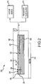
FIG. 2 illustrates a system for forming a composite component using a vacuum and pressurized air in accordance with various embodiments; -
FIG. 3 illustrates a composite material usable to form the composite component ofFIG. 2 in accordance with various embodiments; -
FIG. 4 illustrates a top-down view of the system ofFIG. 2 in accordance with various embodiments; -
FIG. 5 illustrates a system for forming a composite component using a vacuum and pressurized air in accordance with various embodiments; and -
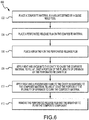
FIG. 6 illustrates a method for forming a composite component using a vacuum and pressurized air in accordance with various embodiments. - The detailed description of various embodiments herein makes reference to the accompanying drawings, which show various embodiments by way of illustration. While these various embodiments are described in sufficient detail to enable those skilled in the art to practice the inventions, it should be understood that other embodiments may be realized and that logical, chemical and mechanical changes may be made without departing from the spirit and scope of the inventions. Thus, the detailed description herein is presented for purposes of illustration only and not of limitation. For example, the steps recited in any of the method or process descriptions may be executed in any order and are not necessarily limited to the order presented.
- Furthermore, any reference to singular includes plural embodiments, and any reference to more than one component or step may include a singular embodiment or step. Also, any reference to attached, fixed, connected or the like may include permanent, removable, temporary, partial, full and/or any other possible attachment option. Additionally, any reference to without contact (or similar phrases) may also include reduced contact or minimal contact.
- Referring to
FIG. 1 , anacelle 100 for a gas turbine engine is illustrated according to various embodiments. Thenacelle 100 may comprise aninlet 110, afan cowl 120, and a thrust reverser 130. Thenacelle 100 may be coupled to a pylon 140 (only part of which is shown), which may mount thenacelle 100 to an aircraft wing or aircraft body. Thenacelle 100 may further comprise anexhaust nozzle 150. Thethrust reverser 130 may comprise a cascade-type thrust reverser, in which bypass air is directed through a cascade in order to apply a reverse thrust to an aircraft, such as during landing. Thenacelle 100 may be disposed about acenterline 105, which may also be the axis of rotation of an engine located within thenacelle 100. - Turning now to
FIG. 2 , asystem 200 may be used to form a composite component for use in thenacelle 100 ofFIG. 1 or in any other composite component, such as for use in an aircraft, a gas turbine engine, or the like. - The
system 200 includes aclose mold tool 202 that defines avolume 203. Thevolume 203 has a shape that corresponds to a desired shape of the final composite component. Theclose mold tool 202 may include, for example, a metal such as anodized aluminum, steel, or the like. Theclose mold tool 202 may include any quantity of parts that may fit together to define thevolume 203 such as one part, two parts, three parts, or the like. - The
system 200 may further include aperforated release film 204. Theperforated release film 204 may include any material that defines a plurality ofopenings 216. For example, theperforated release film 204 may include fluorinated ethylene propylene (FEP) and may be formed or otherwise created to define the plurality ofopenings 216. - In various embodiments, the
perforated release film 204 may include a material having micro-openings that are small enough to prevent fluid from flowing therethrough but sufficiently large to allow air to flow therethrough. - The
system 200 may further include abreather 206. Thebreather 206 may include any woven material that allows a fluid, such as air, to pass therethrough. For example, thebreather 206 may include woven fiberglass, a porous polytetrafluoroethylene (PTFE) glass product such as that sold under the mark ARMALON, or the like. - The
system 200 may further include acomposite material 208. Thecomposite material 208 may include any thermoset material, thermoplastic material, or the like. With brief reference toFIG. 3 , thecomposite material 208 may include a plurality offibers 300 and aresin 302. The plurality offibers 300 may include carbon fibers, glass fibers, or the like. Theresin 302 may include any resin such as epoxy, bis-Maleimide (BMI), polymethacrylimide (PMI), or the like. - Returning reference to
FIG. 2 , thesystem 200 may further include apassageway 210. Thepassageway 210 may be defined by theclose mold tool 202 or may be a separate component that extends through at least a portion of theclose mold tool 202. - The
passageway 210 may be in fluid communication with thevolume 203. Thesystem 200 may further include avacuum source 212 and a pressurizedfluid source 214 which may each be permanently or removably coupled to thepassageway 210. In various embodiments, thevacuum source 212 and the pressurizedfluid source 214 may be separate components and, in various embodiments, thevacuum source 212 and the pressurizedfluid source 214 may be the same component. Thevacuum source 212 may be designed to apply a vacuum to thevolume 203, and the pressurizedfluid source 214 may be designed to apply a pressurized fluid to thevolume 203. For example, the pressurized fluid may include pressurized air. - The
system 200 may further include aheater 218. Theheater 218 may be designed to apply a heat to theclose mold tool 200, or directly to thevolume 203. In either case, the heat applied by theheater 218 may be applied to thecomposite material 208 within thevolume 203. - The
perforated release film 204 may have afilm thickness 220. In various embodiments, thefilm thickness 220 may be between 0.5 thousandths of an inch (0.5 mils, 12.7 micrometers, µm) and 10 mils (254 µm), between 1 mil (25.4 µm) and 5 mils (127 µm), or between 1 mil (25.4 µm) and 3 mils (76.2 µm). - The
breather 206 may have abreather thickness 222. In various embodiments, thebreather thickness 222 may be between 0.5 thousandths of an inch (0.5 mils, 12.7 micrometers, µm) and 20 mils (508 µm), between 1 mil (25.4 µm) and 15 mils (381 µm), or between 1 mil (25.4 µm) and 3 mils (254 µm). - The plurality of
openings 216 may each have anopening width 224. In various embodiments, theopening width 224 may be between 5 mils (127 µm) and 100 mils (2540 µm), between 10 mils (254 µm) and 75 mils (1905 µm), or between 25 mils (635 µm) and 75 mils (1905 µm). - In order to form the composite part, the
composite material 208 may be placed in thevolume 203. Theperforated release film 204 may then be placed on thecomposite material 208, and thebreather 206 may be placed on theperforated release film 204. Theclose mold tool 202 may then be closed such that thepassageway 210 is in fluid communication with thevolume 203. Thevacuum source 212 may apply a vacuum to thevolume 203 while theheater 218 simultaneously applies heat to thevolume 203. The heat that is applied to thevolume 203 may be, for example, between 70 degrees Fahrenheit (70 degrees F, 21.1 degrees Celsius (C)) and 450 degrees F (232 degrees C), between 70 degrees F (21.1 degrees C) and 250 degrees F (121 degrees C), or between 70 degrees F (21.1 degrees C) and 200 degrees F (93.3 degrees C). - Referring to
FIGS. 2 and3 , theheater 218 may cause theresin 302 to melt, and thevacuum source 212 may cause theresin 302 to at least partially fill the plurality ofopenings 216. Stated differently, at least one of the plurality ofopenings 216 may receive a portion of theresin 302. In response to theresin 302 at least partially filling the plurality ofopenings 216, thevacuum source 212 may be removed from thepassageway 210 and the pressurizedfluid source 214 may be coupled to thepassageway 210. For example, a calculation may be performed to determine how much time the heat and vacuum should be applied until the plurality ofopenings 216 are at least partially filled, and the vacuum may be removed after the period of time. In various embodiments, this amount of time may correspond to a maximum time and heat to be applied to theresin 302. As another example, an operator may watch thesystem 200 and may remove the vacuum in response to observing theresin 302 in the plurality ofopenings 216. - At least partially filling the plurality of
openings 216 means that at least someresin 302 is in at least one of the plurality ofopenings 216, i.e., that at least one of the plurality ofopenings 216 is at least partially filled with theresin 302. - The pressurized
fluid source 214 may then apply a pressurized fluid, such as pressurized air, to thevolume 203. Because theresin 302 is in fluid form at this point in time, the pressurized fluid from the pressurizedfluid source 214 may fail to flow through the perforatedrelease film 204 to thecomposite material 208. Theheater 218 may continue to apply the heat as the pressurizedfluid source 214 applies the pressurized fluid, thus curing thecomposite material 208. - After curing of the
composite material 208, thecomposite material 208 may be removed from theclose mold tool 202. Additionally, theperforated release film 204 and thebreather 206 may be removed from thecomposite material 208, resulting in the composite component. - Referring briefly to
FIG. 4 , a top-down cross-sectional view of thesystem 200 after application of the heat and the vacuum is shown. As shown, thebreather 206 is located on theperforated release film 204. As additionally shown, theresin 302 has at least partially filled the plurality ofopenings 216 defined by the perforatedrelease film 204. Thus, theperforated release film 204 is now less porous, reducing the likelihood of the pressurized fluid reaching the composite material beneath the perforatedrelease film 204. - Turning now to
FIG. 5 , anothersystem 500 for forming a composite component is shown. Thesystem 500 is similar to thesystem 200 ofFIG. 2 , but includes twoperforated release films breathers perforated release films release film 204 ofFIG. 2 and defines a plurality ofopenings 516. Each of thebreathers breather 206 ofFIG. 2 and may include woven fibers. Thesystem 500 further includes aclose mold tool 502 that defines avolume 503. Thesystem 500 may include any quantity ofperforated release films breathers - The system further includes a
passageway 510, avacuum source 512, a pressurizedfluid source 514, and aheater 518 that are similar to the corresponding components of thesystem 200 ofFIG. 2 . As theheater 518 applies heat to thecomposite material 508 and thevacuum source 512 applies a vacuum to thevolume 503, resin of thecomposite material 508 may fill the plurality ofopenings 516 of theperforated release films openings 516 are at least partially full of resin, thevacuum source 512 may be removed, and the pressurizedfluid source 514 may apply pressurized fluid to thevolume 503. The pressure and heat may cure thecomposite material 508. After curing of the composite material, theperforated release films breathers - Referring now to
FIG. 6 , amethod 600 for forming a composite component is shown. Themethod 600 may be performed using a system similar to thesystem 200 ofFIG. 2 or thesystem 500 ofFIG. 5 . Themethod 600 may begin inblock 602 in which a composite material may be placed in a volume defined by a close mold tool. The composite material may include, for example, a thermoset material such as a combination of fibers and a resin. - In
block 604, a perforated release film may be placed on the composite material, such as on a surface of the composite material. The perforated release film may include a plurality of openings. - In
block 606, a breather may be placed on the perforated release film. The breather may be designed to allow fluid to flow therethrough. For example, the breather may include a woven material such as woven fiberglass or porous ARMALON. - In
block 608, the close mold tool may be closed, and heat and a vacuum may be applied to the cavity. Application of the heat and the vacuum may cause some of the composite material (such as resin) to fill at least one of the openings of the perforated release film. - In response to the composite material filling the at least the portion of the plurality of openings, the
method 600 may proceed to block 610. Inblock 610, the heat may continue to be applied and a pressurized fluid may also be applied to the cavity. In various embodiments, the heat applied inblock 610 may be greater than, or less than, the amount of heat applied inblock 608. Application of the pressurized fluid and the heat inblock 610 may result in curing of the composite material. - In
block 612, the close mold tool may be opened and the composite material, the perforated release film, and the breather may be removed. Additionally, the perforated release film may be removed from the composite material, further removing the breather from the composite material and resulting in the final composite component. - In various embodiments, a surface treatment may be applied to the surface of the composite component from which the perforated release film was removed. For example, the surface treatment may include application of a surface treatment film, cleaning of the surface, or the like.
- Use of the
method 600 may provide advantages over conventional methods, such as use of an autoclave. For example, use of themethod 600 is less time and effort intensive and results in higher-quality parts than use of an autoclave. - In the detailed description herein, references to "one embodiment", "an embodiment", "various embodiments", etc., indicate that the embodiment described may include a particular feature, structure, or characteristic, but every embodiment may not necessarily include the particular feature, structure, or characteristic. Moreover, such phrases are not necessarily referring to the same embodiment. Further, when a particular feature, structure, or characteristic is described in connection with an embodiment, it is submitted that it is within the knowledge of one skilled in the art to affect such feature, structure, or characteristic in connection with other embodiments whether or not explicitly described. After reading the description, it will be apparent to one skilled in the relevant art(s) how to implement the disclosure in alternative embodiments.
- Benefits, other advantages, and solutions to problems have been described herein with regard to specific embodiments. Furthermore, the connecting lines shown in the various figures contained herein are intended to represent various functional relationships and/or physical couplings between the various elements. It should be noted that many alternative or additional functional relationships or physical connections may be present in a practical system. However, the benefits, advantages, solutions to problems, and any elements that may cause any benefit, advantage, or solution to occur or become more pronounced are not to be construed as critical, required, or essential features or elements of the inventions. The scope of the inventions is accordingly to be limited by nothing other than the appended claims, in which reference to an element in the singular is not intended to mean "one and only one" unless explicitly so stated, but rather "one or more." Moreover, where a phrase similar to "at least one of A, B, or C" is used in the claims, it is intended that the phrase be interpreted to mean that A alone may be present in an embodiment, B alone may be present in an embodiment, C alone may be present in an embodiment, or that any combination of the elements A, B and C may be present in a single embodiment; for example, A and B, A and C, B and C, or A and B and C. Different cross-hatching is used throughout the figures to denote different parts but not necessarily to denote the same or different materials.
- As used herein, the terms "comprises", "comprising", or any other variation thereof, are intended to cover a non-exclusive inclusion, such that a process, method, article, or apparatus that comprises a list of elements does not include only those elements but may include other elements not expressly listed or inherent to such process, method, article, or apparatus.
Claims (15)
- A system (200; 500) for forming a composite component, comprising:a close mold tool (202; 502) defining a cavity (203; 503) that corresponds to a shape of the composite component and configured to receive a composite material (208; 508);a perforated release film (204; 504, 505) defining a plurality of openings (216; 516) and configured to be positioned on a surface of the composite material (208; 508) within the cavity (203; 503); anda breather (206; 506, 507) configured to be positioned on the perforated release film (204; 504, 505), to allow a vacuum to be applied to the composite material (208; 508) through the breather (206; 506, 507) and the plurality of openings (216; 516), and to allow pressurized fluid to be applied to the perforated release film (204; 504) through the breather (206; 506, 507).
- The system (200; 500) of claim 1, wherein the close mold tool (202; 502) further defines a passageway (210; 510) in fluid communication with the cavity (203; 503) and configured to allow the vacuum and the pressurized fluid to be applied to the breather (206; 506, 507) and the perforated release film (204; 504, 505).
- The system (200; 500) of claim 2, further comprising a vacuum source (212; 512) configured to be coupled to the passageway (210; 510) and configured to apply the vacuum to the cavity (203; 503).
- The system (200; 500) of claim 2 or 3, further comprising a pressurized fluid source (214; 514) configured to be coupled to the passageway (210; 510) and configured to apply the pressurized fluid to the cavity (203; 503), wherein, optionally, the pressurized fluid source (214; 514) is configured to apply pressurized air to the cavity (203; 503).
- The system (200; 500) of any preceding claim, further comprising the composite material (208; 508) that includes any thermoset composite material, wherein, optionally, the thermoset composite material includes a plurality of fibers (300) and a resin (302).
- The system (200; 500) of any preceding claim, wherein the perforated release film (204; 504, 505) has a film thickness (220) that is between 1 thousandths of an inch (25.4 micrometers, µm) and 3 thousandths of an inch (76.2 µm), and the breather (206; 506, 507) has a breather thickness (222) that is between 1 thousandth of an inch (25.4 µm) and 10 thousandths of an inch (254 µm).
- The system (200; 500) of any preceding claim, wherein the breather (206; 506, 507) includes at least one of woven fiberglass or a porous polytetrafluoroethylene (PTFE) glass product.
- The system (200; 500) of any preceding claim, wherein:the perforated release film (204; 504, 505) includes fluorinated ethylene propylene (FEP); and/orthe close mold tool (202; 502) includes a metal.
- A system (200; 500) for forming a composite component, comprising:a close mold tool (202; 502) defining a cavity (203; 503) that corresponds to a shape of the composite component and configured to receive a composite material (208; 508);a perforated release film (204; 504, 505) defining a plurality of openings (216; 516) and configured to be positioned on a surface of the composite material (208; 508) within the cavity (203; 503);a breather (206; 506, 507) configured to be positioned on the perforated release film (204; 504, 505);a vacuum source (212; 512) configured to apply a vacuum to the composite material (208; 508) through the breather (206; 506, 507) and the plurality of openings (216; 516); anda pressurized fluid source (214; 514) configured to apply a pressurized fluid to the perforated release film (204; 504, 505) through the breather (206; 506, 507).
- The system (200; 500) of claim 9, wherein the pressurized fluid source (214; 514) is configured to apply pressurized air to the cavity (203; 503).
- The system (200; 500) of any preceding claim, further comprising a heater (218; 518) configured to apply heat to the close mold tool (202; 502) to heat the composite material (208; 508) in the cavity (203; 503) in order to cause the composite material (208; 508) to at least partially fill the plurality of openings (216; 516) of the perforated release film (204; 504, 505) in response to application of the heat and the vacuum, and in order to cure the composite material (208; 508) in the cavity (203; 503) in response to the application of the heat and the pressurized fluid.
- A method of forming a composite component, comprising:placing a composite material (208; 508) in a volume (205; 503) defined by a close mold tool (202; 502);placing a perforated release film (204; 504, 505) defining a plurality of openings (216; 516) on the composite material (208; 508);placing a breather (206; 506, 507) on the perforated release film (204; 504, 505);applying a vacuum to the volume (203; 503) to cause the composite material (208; 508) to at least partially fill the plurality of openings (216; 516) of the perforated release film (204; 504, 505); andapplying a pressurized fluid to the volume (203; 503) to apply pressure to the perforated release film (204; 504, 505) and the composite material (208; 508).
- The method of claim 12, further comprising applying heat to the volume (203; 503) while applying the vacuum to the volume (203; 503) in order to heat the composite material (208; 508) to allow the composite material (208; 508) to fill the at least the portion of the plurality of openings (216; 516), and applying the heat to the volume (203; 503) while applying the pressurized fluid to the volume (203; 503) in order to cure the composite material (208; 508), and, optionally, further comprising removing the perforated release film (204; 504, 505) from the composite material (208; 508) after curing of the composite material (208; 508).
- The method of claim 12 or 13, wherein applying the pressurized fluid to the volume (203; 503) includes applying the pressurized fluid to the volume (203; 503) in response to the composite material (208; 508) filling the at least the portion of the plurality of openings (216; 516) of the perforated release film (204; 504, 505) to reduce a likelihood of the pressurized fluid flowing through the perforated release film (204; 504, 505).
- The method of claim 12, 13 or 14, wherein applying the pressurized fluid to the volume (203; 503) includes applying pressurized air to the volume (203; 503).
Applications Claiming Priority (1)
| Application Number | Priority Date | Filing Date | Title |
|---|---|---|---|
| US16/026,904 US11077629B2 (en) | 2018-07-03 | 2018-07-03 | Vacuum pressurized molding |
Publications (2)
| Publication Number | Publication Date |
|---|---|
| EP3590691A1 true EP3590691A1 (en) | 2020-01-08 |
| EP3590691B1 EP3590691B1 (en) | 2021-05-05 |
Family
ID=66998183
Family Applications (1)
| Application Number | Title | Priority Date | Filing Date |
|---|---|---|---|
| EP19180947.4A Active EP3590691B1 (en) | 2018-07-03 | 2019-06-18 | Vacuum pressurized molding |
Country Status (2)
| Country | Link |
|---|---|
| US (1) | US11077629B2 (en) |
| EP (1) | EP3590691B1 (en) |
Cited By (1)
| Publication number | Priority date | Publication date | Assignee | Title |
|---|---|---|---|---|
| CN111002521A (en) * | 2020-01-13 | 2020-04-14 | 广州市利之叶科技有限公司 | A gas turbine driven plastic thermoforming device |
Citations (2)
| Publication number | Priority date | Publication date | Assignee | Title |
|---|---|---|---|---|
| US5433915A (en) * | 1992-09-01 | 1995-07-18 | Kawasaki Jukogyo Kabushiki Kaisha | Manufacturing method of composite articles from prepregs which avoids internal defects |
| US20060062950A1 (en) * | 2004-09-23 | 2006-03-23 | Usa As Represented By The Administrator Of The National Aeronautics And Space Administration | Support assembly for composite laminate materials during roll press processing |
Family Cites Families (12)
| Publication number | Priority date | Publication date | Assignee | Title |
|---|---|---|---|---|
| US4062917A (en) * | 1976-11-05 | 1977-12-13 | Burlington Industries, Inc. | Method of molding resin-impregnated fabric layer using release sheet and absorbent sheet inside evacuated bag |
| GB2067455A (en) * | 1979-02-20 | 1981-07-30 | Rolls Royce | Composite structure |
| US5122323A (en) * | 1989-12-18 | 1992-06-16 | Sullivan Sr Fletcher R | Method for rapidly laying up and curing thick complex resin matrix composites |
| US5464337A (en) * | 1991-03-27 | 1995-11-07 | The Charles Stark Draper Laboratories | Resin transfer molding system |
| GB0417634D0 (en) | 2004-08-09 | 2004-09-08 | Structural Polymer Systems Ltd | Mould |
| US8834782B2 (en) | 2007-08-07 | 2014-09-16 | William L. Rodman | Composite structures and methods of making same |
| US8696965B2 (en) | 2008-10-20 | 2014-04-15 | Cytec Technology Corp. | Prepregs with improved processing |
| US8652371B2 (en) | 2008-11-20 | 2014-02-18 | Cytec Technology Corp. | Constant pressure infusion process for resin transfer molding |
| BE1019293A5 (en) | 2010-04-15 | 2012-05-08 | Coexpair | METHOD AND DEVICE FOR MOLDING PIECES OF COMPOSITE MATERIAL. |
| US9802476B1 (en) | 2012-05-25 | 2017-10-31 | Robertson Fuel Systems, Llc | Method and system for forming a self-sealing volume using a breather system |
| US9908993B1 (en) | 2014-10-06 | 2018-03-06 | Cornerstone Research Group, Inc. | Hybrid fiber layup and fiber-reinforced polymeric composites produced therefrom |
| US10308000B2 (en) * | 2016-05-24 | 2019-06-04 | The Boeing Company | Method for pre-preg manufacturing |
-
2018
- 2018-07-03 US US16/026,904 patent/US11077629B2/en active Active
-
2019
- 2019-06-18 EP EP19180947.4A patent/EP3590691B1/en active Active
Patent Citations (2)
| Publication number | Priority date | Publication date | Assignee | Title |
|---|---|---|---|---|
| US5433915A (en) * | 1992-09-01 | 1995-07-18 | Kawasaki Jukogyo Kabushiki Kaisha | Manufacturing method of composite articles from prepregs which avoids internal defects |
| US20060062950A1 (en) * | 2004-09-23 | 2006-03-23 | Usa As Represented By The Administrator Of The National Aeronautics And Space Administration | Support assembly for composite laminate materials during roll press processing |
Non-Patent Citations (2)
| Title |
|---|
| CAMPBELL F C ED - CAMPBELL FLAKE C: "Manufacturing processes for advanced composites", 1 January 2004, MANUFACTURING PROCESSES FOR ADVANCED COMPOSITES, ELSEVIER ADVANCED TECHNOLOGY, OXFORD, GB, PAGE(S) 304 - 356, ISBN: 978-1-85617-415-2, XP002580602 * |
| MIRACLE D B ET AL: "Curing", 1 January 2001, ASM HANDBOOK / PREPARED UNDER THE DIRECTION OF THE ASM INTERNATIONAL HANDBOOK COMMITTEE, ASM INTERNATIONAL, MATERIALS PARK, OHIO ,USA, PAGE(S) 486 - 491, ISBN: 978-0-87170-703-1, XP002563889 * |
Cited By (2)
| Publication number | Priority date | Publication date | Assignee | Title |
|---|---|---|---|---|
| CN111002521A (en) * | 2020-01-13 | 2020-04-14 | 广州市利之叶科技有限公司 | A gas turbine driven plastic thermoforming device |
| CN111002521B (en) * | 2020-01-13 | 2021-02-12 | 佛山市亚士康塑料五金有限公司 | A gas turbine driven plastic thermoforming device |
Also Published As
| Publication number | Publication date |
|---|---|
| EP3590691B1 (en) | 2021-05-05 |
| US20200009806A1 (en) | 2020-01-09 |
| US11077629B2 (en) | 2021-08-03 |
Similar Documents
| Publication | Publication Date | Title |
|---|---|---|
| CN113423550B (en) | Improvements relating to wind turbine blade manufacture | |
| US8877114B2 (en) | Method for removing a SMP apparatus from a cured composite part | |
| US9266603B2 (en) | Single-piece propeller and method of making | |
| US8043453B2 (en) | System and method for reworking composites | |
| US8815145B2 (en) | Methods and systems for fabricating composite stiffeners with a rigid/malleable SMP apparatus | |
| US20090166921A1 (en) | Method for Manufacturing a Composite Fiber Component for Aerospace | |
| CA2808923C (en) | Methods and systems for co-bonding or co-curing composite parts using a rigid/malleable smp apparatus | |
| US20130264751A1 (en) | Method of manufacturing resin infused composite parts using a perforated caul sheet | |
| US9481136B2 (en) | Over-molded vacuum barrier and inner mold line bag carrier with soluble details in trapped closed mold tooling | |
| CN106965457A (en) | A kind of compound propeller blade burst shaping is studied with transition Joining Technology | |
| US8734703B2 (en) | Methods and systems for fabricating composite parts using a SMP apparatus as a rigid lay-up tool and bladder | |
| CN101903162A (en) | A method for repairing fiber composite solid components | |
| CN104768726A (en) | System and method for manufacturing monolithic structures using expanding internal tools | |
| US20130049266A1 (en) | Methods and apparatus for molding and curing of composites | |
| US20190210308A1 (en) | Method for repairing a composite stringer with a composite repair cap | |
| EP3590691B1 (en) | Vacuum pressurized molding | |
| US8409487B2 (en) | Processes and systems for manufacturing spars and other hollow structures | |
| EP4074498B1 (en) | Apparatus and method for processing a composite structure | |
| AU2019201057B2 (en) | Caul plates that define channels for distributing resin to composite parts | |
| CA2900635C (en) | Multifunctional mandrel end cap and method | |
| CN117656531A (en) | A helicopter composite blade forming device and method | |
| EP3686105B1 (en) | Systems and methods for aircraft structure surface covers | |
| FR3061070A1 (en) | METHOD FOR PRODUCING A RAIDI AUTO PANEL IN COMPOSITE MATERIALS AND PANEL OBTAINED BY SAID METHOD | |
| EP4667195A1 (en) | Composite article with barrier layer | |
| US20230391025A1 (en) | Smart materials to form nacelle core structure |
Legal Events
| Date | Code | Title | Description |
|---|---|---|---|
| PUAI | Public reference made under article 153(3) epc to a published international application that has entered the european phase |
Free format text: ORIGINAL CODE: 0009012 |
|
| STAA | Information on the status of an ep patent application or granted ep patent |
Free format text: STATUS: THE APPLICATION HAS BEEN PUBLISHED |
|
| AK | Designated contracting states |
Kind code of ref document: A1 Designated state(s): AL AT BE BG CH CY CZ DE DK EE ES FI FR GB GR HR HU IE IS IT LI LT LU LV MC MK MT NL NO PL PT RO RS SE SI SK SM TR |
|
| AX | Request for extension of the european patent |
Extension state: BA ME |
|
| STAA | Information on the status of an ep patent application or granted ep patent |
Free format text: STATUS: REQUEST FOR EXAMINATION WAS MADE |
|
| 17P | Request for examination filed |
Effective date: 20200708 |
|
| RBV | Designated contracting states (corrected) |
Designated state(s): AL AT BE BG CH CY CZ DE DK EE ES FI FR GB GR HR HU IE IS IT LI LT LU LV MC MK MT NL NO PL PT RO RS SE SI SK SM TR |
|
| REG | Reference to a national code |
Ref country code: DE Ref legal event code: R079 Ref document number: 602019004401 Country of ref document: DE Free format text: PREVIOUS MAIN CLASS: B29C0070340000 Ipc: B29C0070460000 |
|
| GRAP | Despatch of communication of intention to grant a patent |
Free format text: ORIGINAL CODE: EPIDOSNIGR1 |
|
| STAA | Information on the status of an ep patent application or granted ep patent |
Free format text: STATUS: GRANT OF PATENT IS INTENDED |
|
| RIC1 | Information provided on ipc code assigned before grant |
Ipc: B29C 70/44 20060101ALI20201116BHEP Ipc: B29C 70/46 20060101AFI20201116BHEP |
|
| INTG | Intention to grant announced |
Effective date: 20201203 |
|
| GRAS | Grant fee paid |
Free format text: ORIGINAL CODE: EPIDOSNIGR3 |
|
| GRAA | (expected) grant |
Free format text: ORIGINAL CODE: 0009210 |
|
| STAA | Information on the status of an ep patent application or granted ep patent |
Free format text: STATUS: THE PATENT HAS BEEN GRANTED |
|
| AK | Designated contracting states |
Kind code of ref document: B1 Designated state(s): AL AT BE BG CH CY CZ DE DK EE ES FI FR GB GR HR HU IE IS IT LI LT LU LV MC MK MT NL NO PL PT RO RS SE SI SK SM TR |
|
| REG | Reference to a national code |
Ref country code: GB Ref legal event code: FG4D |
|
| REG | Reference to a national code |
Ref country code: CH Ref legal event code: EP |
|
| REG | Reference to a national code |
Ref country code: AT Ref legal event code: REF Ref document number: 1389285 Country of ref document: AT Kind code of ref document: T Effective date: 20210515 |
|
| REG | Reference to a national code |
Ref country code: IE Ref legal event code: FG4D |
|
| REG | Reference to a national code |
Ref country code: DE Ref legal event code: R096 Ref document number: 602019004401 Country of ref document: DE |
|
| REG | Reference to a national code |
Ref country code: LT Ref legal event code: MG9D |
|
| REG | Reference to a national code |
Ref country code: AT Ref legal event code: MK05 Ref document number: 1389285 Country of ref document: AT Kind code of ref document: T Effective date: 20210505 |
|
| PG25 | Lapsed in a contracting state [announced via postgrant information from national office to epo] |
Ref country code: HR Free format text: LAPSE BECAUSE OF FAILURE TO SUBMIT A TRANSLATION OF THE DESCRIPTION OR TO PAY THE FEE WITHIN THE PRESCRIBED TIME-LIMIT Effective date: 20210505 Ref country code: LT Free format text: LAPSE BECAUSE OF FAILURE TO SUBMIT A TRANSLATION OF THE DESCRIPTION OR TO PAY THE FEE WITHIN THE PRESCRIBED TIME-LIMIT Effective date: 20210505 Ref country code: FI Free format text: LAPSE BECAUSE OF FAILURE TO SUBMIT A TRANSLATION OF THE DESCRIPTION OR TO PAY THE FEE WITHIN THE PRESCRIBED TIME-LIMIT Effective date: 20210505 Ref country code: BG Free format text: LAPSE BECAUSE OF FAILURE TO SUBMIT A TRANSLATION OF THE DESCRIPTION OR TO PAY THE FEE WITHIN THE PRESCRIBED TIME-LIMIT Effective date: 20210805 Ref country code: AT Free format text: LAPSE BECAUSE OF FAILURE TO SUBMIT A TRANSLATION OF THE DESCRIPTION OR TO PAY THE FEE WITHIN THE PRESCRIBED TIME-LIMIT Effective date: 20210505 |
|
| PG25 | Lapsed in a contracting state [announced via postgrant information from national office to epo] |
Ref country code: IS Free format text: LAPSE BECAUSE OF FAILURE TO SUBMIT A TRANSLATION OF THE DESCRIPTION OR TO PAY THE FEE WITHIN THE PRESCRIBED TIME-LIMIT Effective date: 20210905 Ref country code: GR Free format text: LAPSE BECAUSE OF FAILURE TO SUBMIT A TRANSLATION OF THE DESCRIPTION OR TO PAY THE FEE WITHIN THE PRESCRIBED TIME-LIMIT Effective date: 20210806 Ref country code: RS Free format text: LAPSE BECAUSE OF FAILURE TO SUBMIT A TRANSLATION OF THE DESCRIPTION OR TO PAY THE FEE WITHIN THE PRESCRIBED TIME-LIMIT Effective date: 20210505 Ref country code: PT Free format text: LAPSE BECAUSE OF FAILURE TO SUBMIT A TRANSLATION OF THE DESCRIPTION OR TO PAY THE FEE WITHIN THE PRESCRIBED TIME-LIMIT Effective date: 20210906 Ref country code: SE Free format text: LAPSE BECAUSE OF FAILURE TO SUBMIT A TRANSLATION OF THE DESCRIPTION OR TO PAY THE FEE WITHIN THE PRESCRIBED TIME-LIMIT Effective date: 20210505 Ref country code: NO Free format text: LAPSE BECAUSE OF FAILURE TO SUBMIT A TRANSLATION OF THE DESCRIPTION OR TO PAY THE FEE WITHIN THE PRESCRIBED TIME-LIMIT Effective date: 20210805 Ref country code: PL Free format text: LAPSE BECAUSE OF FAILURE TO SUBMIT A TRANSLATION OF THE DESCRIPTION OR TO PAY THE FEE WITHIN THE PRESCRIBED TIME-LIMIT Effective date: 20210505 Ref country code: LV Free format text: LAPSE BECAUSE OF FAILURE TO SUBMIT A TRANSLATION OF THE DESCRIPTION OR TO PAY THE FEE WITHIN THE PRESCRIBED TIME-LIMIT Effective date: 20210505 |
|
| REG | Reference to a national code |
Ref country code: NL Ref legal event code: MP Effective date: 20210505 |
|
| PG25 | Lapsed in a contracting state [announced via postgrant information from national office to epo] |
Ref country code: NL Free format text: LAPSE BECAUSE OF FAILURE TO SUBMIT A TRANSLATION OF THE DESCRIPTION OR TO PAY THE FEE WITHIN THE PRESCRIBED TIME-LIMIT Effective date: 20210505 |
|
| PG25 | Lapsed in a contracting state [announced via postgrant information from national office to epo] |
Ref country code: SK Free format text: LAPSE BECAUSE OF FAILURE TO SUBMIT A TRANSLATION OF THE DESCRIPTION OR TO PAY THE FEE WITHIN THE PRESCRIBED TIME-LIMIT Effective date: 20210505 Ref country code: ES Free format text: LAPSE BECAUSE OF FAILURE TO SUBMIT A TRANSLATION OF THE DESCRIPTION OR TO PAY THE FEE WITHIN THE PRESCRIBED TIME-LIMIT Effective date: 20210505 Ref country code: EE Free format text: LAPSE BECAUSE OF FAILURE TO SUBMIT A TRANSLATION OF THE DESCRIPTION OR TO PAY THE FEE WITHIN THE PRESCRIBED TIME-LIMIT Effective date: 20210505 Ref country code: DK Free format text: LAPSE BECAUSE OF FAILURE TO SUBMIT A TRANSLATION OF THE DESCRIPTION OR TO PAY THE FEE WITHIN THE PRESCRIBED TIME-LIMIT Effective date: 20210505 Ref country code: CZ Free format text: LAPSE BECAUSE OF FAILURE TO SUBMIT A TRANSLATION OF THE DESCRIPTION OR TO PAY THE FEE WITHIN THE PRESCRIBED TIME-LIMIT Effective date: 20210505 Ref country code: RO Free format text: LAPSE BECAUSE OF FAILURE TO SUBMIT A TRANSLATION OF THE DESCRIPTION OR TO PAY THE FEE WITHIN THE PRESCRIBED TIME-LIMIT Effective date: 20210505 Ref country code: SM Free format text: LAPSE BECAUSE OF FAILURE TO SUBMIT A TRANSLATION OF THE DESCRIPTION OR TO PAY THE FEE WITHIN THE PRESCRIBED TIME-LIMIT Effective date: 20210505 |
|
| REG | Reference to a national code |
Ref country code: DE Ref legal event code: R097 Ref document number: 602019004401 Country of ref document: DE |
|
| REG | Reference to a national code |
Ref country code: BE Ref legal event code: MM Effective date: 20210630 |
|
| PLBE | No opposition filed within time limit |
Free format text: ORIGINAL CODE: 0009261 |
|
| STAA | Information on the status of an ep patent application or granted ep patent |
Free format text: STATUS: NO OPPOSITION FILED WITHIN TIME LIMIT |
|
| PG25 | Lapsed in a contracting state [announced via postgrant information from national office to epo] |
Ref country code: MC Free format text: LAPSE BECAUSE OF FAILURE TO SUBMIT A TRANSLATION OF THE DESCRIPTION OR TO PAY THE FEE WITHIN THE PRESCRIBED TIME-LIMIT Effective date: 20210505 Ref country code: LU Free format text: LAPSE BECAUSE OF NON-PAYMENT OF DUE FEES Effective date: 20210618 |
|
| 26N | No opposition filed |
Effective date: 20220208 |
|
| PG25 | Lapsed in a contracting state [announced via postgrant information from national office to epo] |
Ref country code: IE Free format text: LAPSE BECAUSE OF NON-PAYMENT OF DUE FEES Effective date: 20210618 |
|
| PG25 | Lapsed in a contracting state [announced via postgrant information from national office to epo] |
Ref country code: IS Free format text: LAPSE BECAUSE OF FAILURE TO SUBMIT A TRANSLATION OF THE DESCRIPTION OR TO PAY THE FEE WITHIN THE PRESCRIBED TIME-LIMIT Effective date: 20210905 Ref country code: AL Free format text: LAPSE BECAUSE OF FAILURE TO SUBMIT A TRANSLATION OF THE DESCRIPTION OR TO PAY THE FEE WITHIN THE PRESCRIBED TIME-LIMIT Effective date: 20210505 |
|
| PG25 | Lapsed in a contracting state [announced via postgrant information from national office to epo] |
Ref country code: IT Free format text: LAPSE BECAUSE OF FAILURE TO SUBMIT A TRANSLATION OF THE DESCRIPTION OR TO PAY THE FEE WITHIN THE PRESCRIBED TIME-LIMIT Effective date: 20210505 Ref country code: BE Free format text: LAPSE BECAUSE OF NON-PAYMENT OF DUE FEES Effective date: 20210630 |
|
| REG | Reference to a national code |
Ref country code: CH Ref legal event code: PL |
|
| PG25 | Lapsed in a contracting state [announced via postgrant information from national office to epo] |
Ref country code: LI Free format text: LAPSE BECAUSE OF NON-PAYMENT OF DUE FEES Effective date: 20220630 Ref country code: CH Free format text: LAPSE BECAUSE OF NON-PAYMENT OF DUE FEES Effective date: 20220630 |
|
| PG25 | Lapsed in a contracting state [announced via postgrant information from national office to epo] |
Ref country code: CY Free format text: LAPSE BECAUSE OF FAILURE TO SUBMIT A TRANSLATION OF THE DESCRIPTION OR TO PAY THE FEE WITHIN THE PRESCRIBED TIME-LIMIT Effective date: 20210505 |
|
| PG25 | Lapsed in a contracting state [announced via postgrant information from national office to epo] |
Ref country code: HU Free format text: LAPSE BECAUSE OF FAILURE TO SUBMIT A TRANSLATION OF THE DESCRIPTION OR TO PAY THE FEE WITHIN THE PRESCRIBED TIME-LIMIT; INVALID AB INITIO Effective date: 20190618 |
|
| PG25 | Lapsed in a contracting state [announced via postgrant information from national office to epo] |
Ref country code: MK Free format text: LAPSE BECAUSE OF FAILURE TO SUBMIT A TRANSLATION OF THE DESCRIPTION OR TO PAY THE FEE WITHIN THE PRESCRIBED TIME-LIMIT Effective date: 20210505 |
|
| PG25 | Lapsed in a contracting state [announced via postgrant information from national office to epo] |
Ref country code: TR Free format text: LAPSE BECAUSE OF FAILURE TO SUBMIT A TRANSLATION OF THE DESCRIPTION OR TO PAY THE FEE WITHIN THE PRESCRIBED TIME-LIMIT Effective date: 20210505 |
|
| PG25 | Lapsed in a contracting state [announced via postgrant information from national office to epo] |
Ref country code: MT Free format text: LAPSE BECAUSE OF FAILURE TO SUBMIT A TRANSLATION OF THE DESCRIPTION OR TO PAY THE FEE WITHIN THE PRESCRIBED TIME-LIMIT Effective date: 20210505 |
|
| PGFP | Annual fee paid to national office [announced via postgrant information from national office to epo] |
Ref country code: DE Payment date: 20250520 Year of fee payment: 7 |
|
| PGFP | Annual fee paid to national office [announced via postgrant information from national office to epo] |
Ref country code: GB Payment date: 20250520 Year of fee payment: 7 |
|
| PGFP | Annual fee paid to national office [announced via postgrant information from national office to epo] |
Ref country code: FR Payment date: 20250520 Year of fee payment: 7 |
|
| P01 | Opt-out of the competence of the unified patent court (upc) registered |
Free format text: CASE NUMBER: UPC_APP_0017988_3590691/2025 Effective date: 20251217 |