EP3590662A1 - Operation device, control system, control method, and program - Google Patents
Operation device, control system, control method, and program Download PDFInfo
- Publication number
- EP3590662A1 EP3590662A1 EP19166927.4A EP19166927A EP3590662A1 EP 3590662 A1 EP3590662 A1 EP 3590662A1 EP 19166927 A EP19166927 A EP 19166927A EP 3590662 A1 EP3590662 A1 EP 3590662A1
- Authority
- EP
- European Patent Office
- Prior art keywords
- point
- motion
- command
- leading end
- coordinate system
- Prior art date
- Legal status (The legal status is an assumption and is not a legal conclusion. Google has not performed a legal analysis and makes no representation as to the accuracy of the status listed.)
- Granted
Links
Images









Classifications
-
- B—PERFORMING OPERATIONS; TRANSPORTING
- B25—HAND TOOLS; PORTABLE POWER-DRIVEN TOOLS; MANIPULATORS
- B25J—MANIPULATORS; CHAMBERS PROVIDED WITH MANIPULATION DEVICES
- B25J9/00—Program-controlled manipulators
- B25J9/16—Program controls
- B25J9/1679—Program controls characterised by the tasks executed
- B25J9/1689—Teleoperation
-
- B—PERFORMING OPERATIONS; TRANSPORTING
- B25—HAND TOOLS; PORTABLE POWER-DRIVEN TOOLS; MANIPULATORS
- B25J—MANIPULATORS; CHAMBERS PROVIDED WITH MANIPULATION DEVICES
- B25J9/00—Program-controlled manipulators
- B25J9/16—Program controls
- B25J9/1628—Program controls characterised by the control loop
- B25J9/163—Program controls characterised by the control loop learning, adaptive, model based, rule based expert control
-
- B—PERFORMING OPERATIONS; TRANSPORTING
- B25—HAND TOOLS; PORTABLE POWER-DRIVEN TOOLS; MANIPULATORS
- B25J—MANIPULATORS; CHAMBERS PROVIDED WITH MANIPULATION DEVICES
- B25J13/00—Controls for manipulators
-
- B—PERFORMING OPERATIONS; TRANSPORTING
- B25—HAND TOOLS; PORTABLE POWER-DRIVEN TOOLS; MANIPULATORS
- B25J—MANIPULATORS; CHAMBERS PROVIDED WITH MANIPULATION DEVICES
- B25J9/00—Program-controlled manipulators
- B25J9/0081—Program-controlled manipulators with leader teach-in means
-
- B—PERFORMING OPERATIONS; TRANSPORTING
- B25—HAND TOOLS; PORTABLE POWER-DRIVEN TOOLS; MANIPULATORS
- B25J—MANIPULATORS; CHAMBERS PROVIDED WITH MANIPULATION DEVICES
- B25J9/00—Program-controlled manipulators
- B25J9/06—Program-controlled manipulators characterised by multi-articulated arms
-
- B—PERFORMING OPERATIONS; TRANSPORTING
- B25—HAND TOOLS; PORTABLE POWER-DRIVEN TOOLS; MANIPULATORS
- B25J—MANIPULATORS; CHAMBERS PROVIDED WITH MANIPULATION DEVICES
- B25J9/00—Program-controlled manipulators
- B25J9/16—Program controls
- B25J9/1602—Program controls characterised by the control system, structure, architecture
- B25J9/161—Hardware, e.g. neural networks, fuzzy logic, interfaces, processor
-
- B—PERFORMING OPERATIONS; TRANSPORTING
- B25—HAND TOOLS; PORTABLE POWER-DRIVEN TOOLS; MANIPULATORS
- B25J—MANIPULATORS; CHAMBERS PROVIDED WITH MANIPULATION DEVICES
- B25J9/00—Program-controlled manipulators
- B25J9/16—Program controls
- B25J9/1656—Program controls characterised by programming, planning systems for manipulators
-
- B—PERFORMING OPERATIONS; TRANSPORTING
- B25—HAND TOOLS; PORTABLE POWER-DRIVEN TOOLS; MANIPULATORS
- B25J—MANIPULATORS; CHAMBERS PROVIDED WITH MANIPULATION DEVICES
- B25J9/00—Program-controlled manipulators
- B25J9/16—Program controls
- B25J9/1656—Program controls characterised by programming, planning systems for manipulators
- B25J9/1664—Program controls characterised by programming, planning systems for manipulators characterised by motion, path, trajectory planning
-
- B—PERFORMING OPERATIONS; TRANSPORTING
- B25—HAND TOOLS; PORTABLE POWER-DRIVEN TOOLS; MANIPULATORS
- B25J—MANIPULATORS; CHAMBERS PROVIDED WITH MANIPULATION DEVICES
- B25J9/00—Program-controlled manipulators
- B25J9/16—Program controls
- B25J9/1656—Program controls characterised by programming, planning systems for manipulators
- B25J9/1669—Program controls characterised by programming, planning systems for manipulators characterised by special application, e.g. multi-arm co-operation, assembly, grasping
-
- G—PHYSICS
- G05—CONTROLLING; REGULATING
- G05B—CONTROL OR REGULATING SYSTEMS IN GENERAL; FUNCTIONAL ELEMENTS OF SUCH SYSTEMS; MONITORING OR TESTING ARRANGEMENTS FOR SUCH SYSTEMS OR ELEMENTS
- G05B19/00—Program-control systems
- G05B19/02—Program-control systems electric
- G05B19/42—Recording and playback systems, i.e. in which the program is recorded from a cycle of operations, e.g. the cycle of operations being manually controlled, after which this record is played back on the same machine
-
- G—PHYSICS
- G06—COMPUTING OR CALCULATING; COUNTING
- G06F—ELECTRIC DIGITAL DATA PROCESSING
- G06F3/00—Input arrangements for transferring data to be processed into a form capable of being handled by the computer; Output arrangements for transferring data from processing unit to output unit, e.g. interface arrangements
- G06F3/01—Input arrangements or combined input and output arrangements for interaction between user and computer
- G06F3/03—Arrangements for converting the position or the displacement of a member into a coded form
- G06F3/033—Pointing devices displaced or positioned by the user, e.g. mice, trackballs, pens or joysticks; Accessories therefor
- G06F3/0346—Pointing devices displaced or positioned by the user, e.g. mice, trackballs, pens or joysticks; Accessories therefor with detection of the device orientation or free movement in a three-dimensional [3D] space, e.g. 3D mice, 6-DOF [six degrees of freedom] pointers using gyroscopes, accelerometers or tilt-sensors
Definitions
- the present invention relates to an operation device, a control system, a control method, and a program.
- JP 2011-224696A discloses a teaching reproduction apparatus that includes a controller and a teaching pendant.
- the controller controls motions of a robot.
- the teaching pendant is used by an operator to teach the motions to the robot.
- JP 2011-224696A The contents of JP 2011-224696A are incorporated herein by reference in their entirety.
- an operation device includes an operation inputter, a screen outputter, a device posture detector, a coordinate system turner, a command generator, a command convertor, and a command outputter.
- the operation inputter is configured to operate a robot.
- the robot includes a leading end and a multi-articular arm configured to change a position and a posture of the leading end.
- the screen outputter is configured to output, to the operation inputter, at least one operation image on which a motion command for the leading end of the robot is input.
- the device posture detector is configured to detect a posture of the operation inputter in a first coordinate system that is for controlling the robot.
- the coordinate system turner is configured to, based on the posture of the operation inputter, turn a second coordinate system turnable relative to the first coordinate system.
- the command generator is configured to, upon execution of a point operation of specifying at least one point on the operation image, determine a motion direction of the leading end of the robot in the second coordinate system such that the motion direction is correlated with a positional relationship between the one point and a reference point on the operation image.
- the command generator is configured to determine a motion scalar quantity of the leading end of the robot such that the motion scalar quantity is correlated with a distance between the one point and the reference point.
- the command generator is configured to generate the motion command such that the motion command includes the motion direction and the motion scalar quantity.
- the command convertor is configured to convert the motion command into a first-coordinate-system motion command for the leading end of the robot in the first coordinate system.
- the command outputter is configured to output a control command for controlling the robot based on the first-coordinate-system motion command.
- a control system includes the above-described operation device and a controller.
- the controller is configured to, based on the control command, control the robot to move the leading end of the robot using the multi-articular arm.
- a control method is performed in an operation device for operating a robot that includes a leading end and a multi-articular arm configured to change a position and a posture of the leading end.
- the control method includes outputting at least one operation image to an operation inputter.
- a posture of the operation inputter in a first coordinate system that is for controlling the robot is detected.
- a second coordinate system turnable relative to the first coordinate system is turned.
- a motion direction of the leading end of the robot in the second coordinate system is determined such that the motion direction is correlated with a positional relationship between the one point and a reference point on the operation image;
- a motion scalar quantity of the leading end of the robot is determined such that the motion scalar quantity is correlated with a distance between the one point and the reference point; and
- a motion command for the leading end of the robot is generated.
- the motion command includes the motion direction and the motion scalar quantity.
- the motion command is converted into a first-coordinate-system motion command for the leading end of the robot in the first coordinate system.
- a control command for controlling the robot based on the first-coordinate-system motion command is output.
- a program is for causing an operation device for operating a robot to perform a control method.
- the robot includes a leading end and a multi-articular arm configured to change a position and a posture of the leading end.
- the control method includes outputting at least one operation image to an operation inputter.
- a posture of the operation inputter in a first coordinate system that is for controlling the robot is detected.
- a second coordinate system turnable relative to the first coordinate system is turned.
- a motion direction of the leading end of the robot in the second coordinate system is determined such that the motion direction is correlated with a positional relationship between the one point and a reference point on the operation image;
- a motion scalar quantity of the leading end of the robot is determined such that the motion scalar quantity is correlated with a distance between the one point and the reference point; and
- a motion command for the leading end of the robot is generated.
- the motion command includes the motion direction and the motion scalar quantity.
- the motion command is converted into a first-coordinate-system motion command for the leading end of the robot in the first coordinate system.
- a control command for controlling the robot based on the first-coordinate-system motion command is output.
- a robot system 1 is a system that causes a robot to automatically repeat a motion taught in advance by an operator.
- Example applications of the robot system 1 include, but are not limited to, industrial applications in which robots perform work such as machining, processing, and assembly work.
- the robot system 1 includes a robot 10 and a control system 100.
- the robot 10 is a six-axis vertical multi-articular robot and includes a base 11, a leading end 12, and a multi-articular arm 20.
- the base 11 is mounted or placed on a floor surface of a workspace of the robot 10.
- the multi-articular arm 20 connects the base 11 and the leading end 12 to each other.
- the multi-articular arm 20 includes a plurality of joints. By changing the motion angles of the plurality of joints, the multi-articular arm 20 changes the position and the posture of the leading end 12 relative to the base 11.
- the multi-articular arm 20 includes a turnable portion 21, a first arm 22, a second arm 23, a wrist 24, and actuators 41, 42, 43, 44, 45, and 46.
- the turnable portion 21 is mounted on an upper portion of the base 11 turnably about vertical axis Ax1.
- the multi-articular arm 20 includes a joint 31.
- the joint 31 makes a turnable portion 21 turnable about the axis Ax1.
- the first arm 22 is connected to the turnable portion 21 swingably about axis Ax2, which crosses or is orthogonal to the axis Ax1.
- the multi-articular arm 20 includes a joint 32.
- the joint 32 makes the first arm 22 swingable about the axis Ax2. It is to be noted that when axes "cross" each other, this means that the axes may be skew axes, as if the axes are in aligned in "grade separation" arrangement. The same applies in the following description.
- the second arm 23 is connected to the base end of the first arm 22 swingably about axis Ax3, which crosses the axis Ax1.
- the multi-articular arm 20 includes a joint33.
- the joint33 makes the second arm 23 swingable about the axis Ax3.
- the axis Ax3 may be parallel to the axis Ax2.
- the wrist 24 includes a turnable arm 26 and a swingable arm 27.
- the turnable arm 26 extends in the center of the second arm 23 and protrudes beyond the leading end of the second arm 23.
- the turnable arm 26 is turnable about axis Ax4, which coincides with the center of the second arm 23.
- the multi-articular arm 20 includes a joint 34.
- the joint 34 makes the turnable arm 26 turnable about the axis Ax4.
- the swingable arm 27 is connected to the leading end of the turnable arm 26 swingably about axis Ax5, which crosses or is orthogonal to the axis Ax4.
- the multi-articular arm 20 includes a joint 35.
- the joint 35 makes the swingable arm 27 swingable about the axis Ax5.
- the leading end 12 is connected to the leading end of the swingable arm 27 turnably about axis Ax6, which coincides with the center of the swingable arm 27.
- the multi-articular arm 20 includes a joint 36.
- the joint 36 makes the leading end 12 turnable about the axis Ax6.
- the actuators 41, 42, 43, 44, 45, and 46 are driven by electric motors to drive the plurality of joints 31, 32, 33, 34, 35, and 36 of the multi-articular arm 20.
- the actuator 41 causes the turnable portion 21 to turn about the axis Ax1;
- the actuator 42 causes the first arm 22 to swing about the axis Ax2;
- the actuator 43 causes the second arm 23 to swing about the axis Ax3;
- the actuator 44 causes the turnable arm 26 to turn about the axis Ax4;
- the actuator 45 causes the swingable arm 27 to swing about the axis Ax5;
- the actuator 46 causes the leading end 12 to turn about axis Ax6. That is, the actuators 41 to 46 respectively drive the joints 31 to 36.
- the above-described configuration of the robot 10 has been presented for example purposes only; the robot 10 may have any other configuration insofar as the robot 10 is capable of changing the position and the posture of the leading end of the robot 10 relative to the base of the robot 10 using a multi-articular arm.
- the robot 10 may be a seven-axis robot, with a redundant axis added to the above-described six-axis vertical multi-articular robot.
- the robot 10 may be a "SCARA (Selective Compliance Assembly Robot Arm)" robot.
- the control system 100 is a system to control the robot 10, and includes a controller 200 and an operation device 300.
- the controller 200 stores, in the form of motion programs, details of motions of the robot 10 taught by the operator, and controls the robot 10 based on the motion programs.
- the operation device 300 obtains an operation input made by the operator, generates a command that is based on the operation input, and outputs the command to the controller 200.
- An example configuration of the controller 200 and an example configuration of the operation device 300 will be described in detail below. Controller
- the controller 200 performs: based on a motion program, controlling the robot 10 to move the leading end 12 using the multi-articular arm 20 (this control will be hereinafter referred to as “play mode control”); and, based on a control command from the operation device 300, controlling the robot 10 to move the leading end 12 using the multi-articular arm 20 (this control will be hereinafter referred to as “teaching mode control”).
- the controller 200 includes functional configurations (hereinafter referred to as "functional modules”) such as a model information storage 211, a program storage 212, an inverse kinematics operator 213, and a control executor 214.
- the model information storage 211 stores model information including the sizes of the elements of the robot 10 (for example, the lengths of the first arm 22, the second arm 23, the turnable arm 26, and the swingable arm 27).
- the program storage 212 stores, in the form of motion programs, details of motions taught by the operator through the operation device 300.
- Each motion program includes a plurality of motion commands aligned in time order.
- the motion commands include a movement command that specifies a target position and a target posture of the leading end 12 relative to the base 11.
- the inverse kinematics operator 213 performs an inverse kinematics operation to calculate joint angle target values (motion angle target values of the joints 31, 32, 33, 34, 35, and 36) for moving the leading end 12 based on the target position and the target posture of the leading end 12.
- joint angle target values motion angle target values of the joints 31, 32, 33, 34, 35, and 36
- the inverse kinematics operator 213 calculates joint angle target values for moving the leading end 12.
- the inverse kinematics operator 213 calculates joint angle target values for moving the leading end 12 based on a target position and a target posture of the leading end 12 specified by the motion command of the motion program.
- control executor 214 controls the multi-articular arm 20 to drive the joints 31, 32, 33, 34, 35, and 36 using the actuators 41, 42, 43, 44, 45, and 46.
- the operation device 300 When the controller 200 performs the teaching mode control, the operation device 300 generates a control command for causing the robot 10 to make a motion based on a motion-teaching operation input, and outputs the control command to the controller 200.
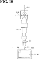
- the operation device 300 is a "tablet terminal", and includes a touch panel 381 and a posture sensor 382.
- the touch panel 381 (operation inputter) is an input device made up of a display device with a contact position detection device superimposed on the display device.
- Examples of the display device include, but are not limited to, a liquid crystal monitor and an organic EL monitor.
- a non-limiting example of the contact position detection device is a touch pad.
- the touch panel 381 receives an operation input in the form of a contact on the screen of the display device.
- the posture sensor 382 detects the posture of the operation device 300 (that is, the posture of the touch panel 381).
- a non-limiting example of the posture sensor 382 is a gyro sensor.
- the gyro sensor detects changes in the posture of the operation device 300 (that is, changes in the posture of the touch panel 381) about three axes approximately orthogonal to each other.
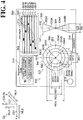
- the operation device 300 performs: detecting, using the posture sensor 382, the posture of the touch panel 381 in a first coordinate system C1, which is used to control the robot 10; turning a second coordinate system C2, which is turnable relative to the first coordinate system C1, based on the posture of the touch panel 381 (see FIG. 9 ); based on an operation input on the touch panel 381, generating a motion command for the leading end 12 in the second coordinate system C2; converting the motion command for the leading end 12 into a first-coordinate-system motion command for the leading end 12 in the first coordinate system C1; outputting a control command for controlling the robot based on the first-coordinate-system motion command 10.
- the first coordinate system C1 may be any coordinate system with which the position and the posture of the leading end 12 relative to the base 11 are uniquely determined.
- the first coordinate system C1 is a coordinate system fixed to the base 11, and includes three coordinate axes (X axis C11, Y axis C12, and Z axis C13) approximately orthogonal to each other.
- the Z axis C13 is a vertical axis (perpendicular to a horizontal surface), and the upward direction of the Z axis C13 is the positive direction.
- the second coordinate system C2 includes three coordinate axes (X axis C21, Y axis C22, and Z axis C23) approximately orthogonal to each other.
- the turning angle of the second coordinate system C2 relative to the first coordinate system C1 is defined based on such an initial state that the X axis C21, the Y axis C22, and the Z axis C23 respectively coincide with the X axis C11, the Y axis C12, and the Z axis C13.
- the operation device 300 may further perform: outputting screen data to the touch panel 381 so that an operation screen including at least one operation image is displayed on the touch panel 381.
- the operation device 300 may perform: determining a motion direction of the leading end 12 in the second coordinate system C2 such that the motion direction is correlated with a positional relationship between the one point and a reference point on the operation image; determining a motion scalar quantity of the leading end 12 such that the motion scalar quantity is correlated with the distance between the one point and the reference point; and generating a motion command for the leading end 12 such that the motion command includes the motion direction and the motion scalar quantity.
- the operation device 300 may further perform: regulating turning of the second coordinate system C2 about at least one axis.
- the operation device 300 includes an operation inputter 311, an input content identifier 312, a screen outputter 313, a model data storage 314, a joint information storage 315, an angle information obtainer 316, and an input content storage 317.
- the operation device 300 includes a device posture detector 321, a posture calculator 322, a coordinate system turner 323, a coordinate system turning regulator 324, a mode switch 325, a calibrator 351, and an unsetting notifier 352.
- the operation device 300 includes a command generator 330, a command convertor 341, and a command outputter 342.
- the operation inputter 311 is an inputter through which the robot 10 is operated. Specifically, the operation inputter 311 displays an operation screen dedicated to receiving operation inputs, and receives an operation input on the operation screen.
- Example operation inputs include, but are not limited to, a point operation and a drugging operation.
- a point operation is an operation of specifying at least one point on an operation screen.
- a point operation encompasses an operation of simultaneously specifying a plurality of points on an operation screen.
- a drugging operation is an operation of specifying at least one point on an operation screen and moving the one point.
- a drugging operation encompasses an operation of specifying a plurality of points on an operation screen and moving the plurality of points.
- the operation inputter 311 is implemented by the touch panel 381.
- the operation inputter 311 displays an operation screen on the touch panel 381 and receives, as an operation input, a touch operation on the operation screen of the touch panel 381.
- the input content identifier 312 identifies the content of the operation input that has been made on the operation inputter 311. Specifically, based on a positional relationship between the position of the touch operation on the touch panel 381 (hereinafter referred to as "touch position") and the operation screen, the input content identifier 312 identifies the content of the operation input that has been made on the operation inputter 311. For example, when the operation screen includes at least one operation image and the touch position is located within the operation image, the input content identifier 312 identifies the content of the operation made on the operation image based on where in the operation image the point operation position is located. More specifically, when the operation screen includes an image of one button and the touch position is located within the image of the button, the input content identifier 312 determines that an operation of pressing the button has been made.
- the model data storage 314 stores model data of operation screens to be displayed on the operation inputter 311.
- the model data storage 314 may store model data of a plurality of different operation screens.
- the joint information storage 315 stores, on an individual joint basis (that is, for each of the plurality of joints 31, 32, 33, 34, 35, and 36), information that includes movable angle (this information will be hereinafter referred to as "joint information").
- the angle information obtainer 316 obtains status information indicating the current angles of the joints 31, 32, 33, 34, 35, and 36. Specifically, the angle information obtainer 316 obtains the status information (indicating the current angles of the joints 31, 32, 33, 34, 35, and 36) from the control executor 214 of the controller 200.
- the input content storage 317 stores the content of the operation input that has been made on the operation inputter 311 and that has been identified by the input content identifier 312.
- the content stored in the input content storage 317 is referred to at the time of performing processing based on the operation input.
- the screen outputter 313 outputs, to the operation inputter 311, screen data so that the operation inputter 311 displays an operation screen including at least one operation image. It is possible for the screen outputter 313 to select one operation screen from among a plurality of different operation screens according to the operation input on the operation inputter 311, and to output screen data of the selected operation screen to the operation inputter 311. Specifically, based on the operation input on the operation inputter 311, the screen outputter 313 chooses one piece of model data from among a plurality of different pieces of model data stored in the model data storage 314, and generates screen data based on the model data.
- the screen outputter 313 may output, to the operation inputter 311, screen data of an image of an angle indicator that indicates a combination of an angle status and an angle limit of each of the joints 31, 32, 33, 34, 35, and 36 so that the operation inputter 311 displays an operation screen including the image of the angle indicator.
- the screen outputter 313 generates data for displaying the angle indicator based on: the joint information of the joints 31, 32, 33, 34, 35, and 36 stored in the joint information storage 315; and the status information of the joints 31, 32, 33, 34, 35, and 36 obtained by the angle information obtainer 316.
- the screen outputter 313 may update the content displayed on the operation screen based on the content of the operation input identified by the input content identifier 312. Specifically, when the operation input has been determined as being targeted at a particular operation image, the screen outputter 313 updates the screen data to indicate that the operation has been made by changing how the operation image is displayed. More specifically, when the operation input has been determined as being an operation of pressing a button on the operation screen, the screen outputter 313 updates the screen data to highlight the button.
- the plurality of different operation screens include an operation screen 400 and an operation screen 500.
- the operation screen 400 is used in a fixed coordinate system mode.
- the operation screen 500 is used in a movable coordinate system mode.
- the fixed coordinate system mode is an operation mode in which to input the first-coordinate-system motion command (for moving the leading end 12 in the first coordinate system C1).
- the movable coordinate system mode is an operation mode in which to input the motion command for the leading end 12 in the second coordinate system C2, which is turnable relative to the first coordinate system C1.
- the operation screen 400 includes position command inputters 421, 422, and 423, turning command inputters 431, 432, and 433, and input mode switch button 411.
- the position command inputter 421 is an inputter through which to specify the position of the leading end 12 on the X axis C11.
- the position command inputter 422 is an inputter through which to specify the position of the leading end 12 on the Y axis C12.
- the position command inputter 423 is an inputter through which to specify the position of the leading end 12 on the Z axis C13.
- the turning command inputter 431 is an inputter through which to specify the turning angle of the leading end 12 about the X axis C11.
- the turning command inputter 432 is an inputter through which to specify the turning angle of the leading end 12 about the Y axis C12.
- the turning command inputter 433 is an inputter through which to specify the turning angle of the leading end 12 about the Z axis C13.
- the input mode switch button 411 is a button with which to switch the operation screen 400 to another operation screen. It is to be noted that the operation device 300 may include a button to switch between operation screens outside the touch panel 381. In this case, the operation screen 400 may not necessarily include the input mode switch button 411.
- the operation screen 500 includes a regulation mode setting image 511, at least one operation image 512, an angle indicator 513, a calibration button 514, and an input mode switch button 515.
- the regulation mode setting image 511 is an image on which to choose between a regulation mode and a free mode associated with the turning of the second coordinate system C2 relative to the first coordinate system C1.
- the regulation mode the turning of the second coordinate system C2 about at least one axis is regulated.
- the free mode the turning of the second coordinate system C2 is not regulated about any of the axes.
- a non-limiting example of the regulation mode is such a mode that the turning of the second coordinate system C2 about an axis perpendicular to the reference axis RL, which extends in one direction, is regulated while the turning of the second coordinate system C2 about the reference axis RL is allowed. This mode will be hereinafter referred to as "first regulation mode".
- the reference axis RL may be a vertical axis.
- the reference axis RL coincides with the Z axis C13 of the first coordinate system C1.
- the Z axis C23 coincides with the Z axis C13, and the turning of the second coordinate system C2 about the Z axis C13 is allowed while the turning of the second coordinate system C2 about the X axis C11 and the Y axis C12 is regulated (for example, prohibited).
- the regulation mode will not be limited to the above-described first regulation mode.
- the regulation mode setting image 511 may be able to choose a mode in which to regulate the turning of the second coordinate system C2 about any one axis alone.
- the at least one operation image 512 is an image on which to input the motion command for the leading end 12 in the second coordinate system C2.
- the at least one operation image 512 includes a movement tool image.
- the movement tool image is an image on which to input the motion command for the leading end 12 in the second coordinate system C2.
- the at least one operation image 512 additionally includes a first movement tool image 521 and a second movement tool image 522.
- the first movement tool image 521 is an image on which to input a motion command for the leading end 12 along the reference axis RL (the Z axes C13 and C23).
- the second movement tool image 522 is an image on which to input a motion command for the leading end 12 along a surface perpendicular to the reference axis RL (for example, a plane including the X axis C21 and the Y axis C22).
- the first movement tool image 521 includes one one-dimensional operation system 530.
- the one-dimensional operation system 530 is drawn along one drawn line 532, and corresponds to one movement line ML3, which is set in the second coordinate system C2.
- the drawn line 532 is a linear line extending in the vertical directions of the operation screen 500
- the movement line ML3 is a linear line extending along the Z axis C23.
- the one-dimensional operation system 530 includes a plurality of point areas 533A and 533B and a plurality of point areas 534A and 534B.
- the point areas 533A and 533B are aligned in this order in the upward direction from one point on the drawn line 532 (hereinafter referred to as "reference point 531").
- the point areas 534A and 534B are aligned in this order in the downward direction from the reference point 531.
- the point areas 533A, 533B, 534A, and 534B are areas in which to specify: a movement direction in which the leading end 12 moves along the movement line ML3; and a motion scalar quantity of the leading end 12 along the movement line ML3.
- the movement direction of the leading end 12 is determined based on positional relationships that the reference point 531 has with the point areas 533A, 533B, 534A, and 534B. For example, when one of the point areas 533A and 533B, which are upper in position than the reference point 531, has been chosen (by, for example, a point operation), the movement direction of the leading end 12 is determined as the positive direction of the Z axis C23. When one of the point areas 534A and 534B, which are lower in position than the reference point 531, has been chosen, the movement direction of the leading end 12 is determined as the negative direction of the Z axis C23.
- the motion scalar quantity by which the leading end 12 moves is determined based on the distances from the reference point 531 to the point areas 533A, 533B, 534A, and 534B. Specifically, the point areas 533B and 534B are farther away from the reference point 531 than the point areas 533A and 534A are from the reference point 531, and when one of the point areas 533B and 534B has been chosen, the motion scalar quantity by which the leading end 12 moves is determined as a higher value than when the point area 533A or 534A has been chosen.
- the widths of the plurality of point areas 533A, 533B, 534A, and 534B may increase as the point areas 533A, 533B, 534A, and 534B are farther away from the reference point 531.
- the width, W2 , of each of the point areas 533B and 534B is larger than the width, W1 , of each of the point areas 533A and 534A.
- the one-dimensional operation system 530 has an inverse triangle area that gradually increases in width in the upward direction from the reference point 531.
- a lower portion of the inverse triangle area constitutes the point area 533A
- an upper portion of the inverse triangle area constitutes the point area 533B.
- the one-dimensional operation system 530 has a triangle area that gradually increases in width in the downward direction from the reference point 531.
- An upper portion of the triangle area constitutes the point area 534A, and a lower portion of the triangle area constitutes the point area 534B.
- the second movement tool image 522 includes a plurality of one-dimensional operation systems drawn along a plurality of drawn lines that cross each other.
- the plurality of one-dimensional operation systems respectively correspond to a plurality of movement lines that cross each other in the second coordinate system C2.
- the second movement tool image 522 includes two one-dimensional operation systems 540 and 550.
- the one-dimensional operation systems 540 and 550 are respectively drawn along two drawn lines 541 and 551, which are orthogonal to each other.
- the one-dimensional operation systems 540 and 550 respectively correspond to movement lines ML1 and ML2.
- the movement lines ML1 and ML2 are orthogonal to each other in the second coordinate system C2.
- the drawn line 541 is a linear line extending in the vertical directions of the operation screen 500, and the movement line ML1 is a linear line along the X axis C21.
- the drawn line 551 is a linear line extending in the right-left directions of the operation screen 500, and the movement line ML2 is a linear line along the Y axis C22.
- the one-dimensional operation system 540 includes a plurality of point areas 543A, 543B, and 543C and a plurality of point areas 544A, 544B, and 544C.
- the point areas 543A, 543B, and 543C are aligned in this order in the upward direction from the node of the drawn lines 541 and 551 (hereinafter referred to as "reference point 542").
- the point areas 544A, 544B, and 544C are aligned in this order in the downward direction from the reference point 542.
- the point areas 543A, 543B, 543C, 544A, 544B, and 544C are areas in which to specify: a movement direction in which the leading end 12 moves along the movement line ML1; and a motion scalar quantity of the leading end 12 along the movement line ML1.
- the movement direction of the leading end 12 is determined based on positional relationships that the reference point 542 has with the point areas 543A, 543B, 543C, 544A, 544B, and 544C. Specifically, when one of the point areas 543A, 543B, and 543C, which are upper in position than the reference point 542, has been chosen, the movement direction of the leading end 12 is determined as the positive direction of the X axis C21. When one of the point areas 544A, 544B, and 544C, which are lower in position than the reference point 542, has been chosen, the movement direction of the leading end 12 is determined as the negative direction of the X axis C21.
- the motion scalar quantity by which the leading end 12 moves is determined based on the distances from the reference point 542 to the point areas 543A, 543B, 543C, 544A, 544B, and 544C. Specifically, the point areas 543B and 544B are farther away from the reference point 542 than the point areas 543A and 544A are from the reference point 542, and when one of the point areas 543B and 544B has been chosen, the motion scalar quantity by which the leading end 12 moves is determined at a higher value than when the point area 543A or 544A has been chosen.
- the point areas 543C and 544C are farther away from the reference point 542 than the point areas 543B and 544B are from the reference point 542, and when one of the point areas 543C and 544C has been chosen, the motion scalar quantity by which the leading end 12 moves is determined as an even higher value than when the point area 543B or 544B has been chosen.
- the widths of the plurality of point areas 543A, 543B, 543C, 544A, 544B, and 544C may increase as the point areas 543A, 543B, 543C, 544A, 544B, and 544C are farther away from the reference point 542.
- the width, W12 , of each of the point areas 543B and 544B may be larger than the width, W11 , of each of the point areas 543A and 544A
- the width, W13 , of each of the point areas 543C and 544C may be even larger than the widths W12 of each of the point areas 543B and 544B.
- the one-dimensional operation system 540 has a first fan-shaped area.
- the first fan-shaped area gradually increases in width in the upward direction from the reference point 542.
- a center portion of the first fan-shaped area constitutes the point area 543A
- an outer circumferential portion of the first fan-shaped area constitutes the point area 543C.
- the portion between the center portion and the outer circumferential portion constitutes the point area 543B.
- the one-dimensional operation system 540 also has a second fan-shaped area.
- the second fan-shaped area gradually increases in width in the downward direction from the reference point 542.
- a center portion of the second fan-shaped area constitutes the point area 544A, and an outer circumferential portion of the second fan-shaped area constitutes the point area 544C.
- the portion between the center portion and the outer circumferential portion constitutes the point area 544B.
- the one-dimensional operation system 550 includes a plurality of point areas 553A, 553B, and 553C and a plurality of point areas 554A, 554B, and 554C.
- the point areas 553A, 553B, and 553C are aligned in this order in the left direction from the reference point 542.
- the point areas 554A, 554B, and 554C are aligned in this order in the right direction from the reference point 542.
- the point areas 553A, 553B, 553C, 554A, 554B, and 554C are areas in which to specify: a movement direction in which the leading end 12 moves along the movement line ML2; and a motion scalar quantity of the leading end 12 along the movement line ML2.
- the movement direction of the leading end 12 is determined based on positional relationships that the reference point 542 has with the point areas 553A, 553B, 553C, 554A, 554B, and 554C. Specifically, the point areas 553A, 553B, and 553C are located on the left side of the reference point 542, and when one of the point areas 553A, 553B, and 553C has been chosen, the movement direction of the leading end 12 is determined as the positive direction of the Y axis C22.
- the point areas 554A, 554B, and 554C are located on the right side of the reference point 542, and when one of the point areas 554A, 554B, and 554C has been chosen, the movement direction of the leading end 12 is determined as the negative direction of the Y axis C22.
- the motion scalar quantity by which the leading end 12 moves is determined based on the distances from the reference point 542 to the point areas 553A, 553B, 553C, 554A, 554B, and 554C. Specifically, the point areas 553B and 554B are farther away from the reference point 542 than the point areas 553A and 554A are from the reference point 542, and when one of the point areas 553B and 554B has been chosen, the motion scalar quantity by which the leading end 12 moves is determined as a higher value than when the point area 553A or 554A has been chosen.
- the point areas 553C and 554C are even farther away from the reference point 542 than the point areas 553B and 554B are from the reference point 542, and when one of the point areas 553C and 554C has been chosen, the motion scalar quantity by which the leading end 12 moves is determined as an even higher value than when the point area 553B or 554B has been chosen.
- the widths of the plurality of point areas 553A, 553B, 553C, 554A, 554B, and 554C may increase as the point areas 553A, 553B, 553C, 554A, 554B, and 554C are farther away from the reference point 542.
- the width, W22, of each of the point areas 553B and 554B is larger than the width, W21, of each of the point areas 553A and 554A
- the width, W23, of each of the point areas 553C and 554C is even larger than the width, W22, of each of the point areas 553B and 554B.
- the one-dimensional operation system 550 has a third fan-shaped area.
- the third fan-shaped area gradually increases in width in the left direction from the reference point 542.
- a center portion of the third fan-shaped area constitutes the point area 553A, and an outer circumferential portion of the third fan-shaped area constitutes the point area 553C.
- the portion between the center portion and the outer circumferential portion constitutes the point area 553B.
- the one-dimensional operation system 550 also has a fourth fan-shaped area.
- the fourth fan-shaped area gradually increases in width in the right direction from the reference point 542.
- a center portion of the fourth fan-shaped area constitutes the point area 554A, and an outer circumferential portion of the fourth fan-shaped area constitutes the point area 554C.
- the portion between the center portion and the outer circumferential portion constitutes the point area 554B.
- the angle indicator 513 is an image that displays a combination of an angle status and angle limits of each of the joints 31, 32, 33, 34, 35, and 36.
- the angle indicator 513 includes: a plurality of angle bars 561A, 561B, 561C, 561D, 561E, and 561F; and limit lines 562 and 563.
- the angle bars 561A, 561B, 561C, 561D, 561E, and 561F respectively correspond to the plurality of joints 31, 32, 33, 34, 35, and 36.
- the angle bars 561A, 561B, 561C, 561D, 561E, and 561F are aligned in the vertical directions and extend in the right-left directions.
- the angle bars 561A, 561B, 561C, 561D, 561E, and 561F each include a status marker 564.
- the status marker 564 is movable in the right-left directions.
- the joint angle of each joint is indicated by the position of the status marker 564 in the right-left directions. Specifically, as the joint angle increases, the status marker 564 moves in the right direction.
- the limit line 562 is a line indicating a lower limit of the joint angle, and crosses the left ends of the angle bars 561A, 561B, 561C, 561D, 561E, and 561F.
- the limit line 563 is a line indicating an upper limit of the joint angle, and crosses the right ends of the angle bars 561A, 561B, 561C, 561D, 561E, and 561F.
- the calibration button 514 is a button on which to instruct that the posture of the second coordinate system C2 relative to the first coordinate system C1 be a preset initial posture.
- a non-limiting example of the initial posture is such a posture that the X axis C21, the Y axis C22, and the Z axis C23 respectively coincide with the X axis C11, the Y axis C12, and the Z axis C13.
- the input mode switch button 515 is a button with which to switch the operation screen 500 to another operation screen.
- the operation device 300 may include a button to switch between operation screens outside the touch panel 381, in which case the operation screen 500 may not necessarily include the input mode switch button 515.
- the plurality of different operation screens may include other operation screens than the operation screens 400 and 500.
- a plurality of different operation screens may include an operation screen on which to operate the robot 10 in a mode different from the fixed coordinate system mode and the movable coordinate system mode (for example, an operation mode in which the leading end 12 moves in a coordinate system different from the first coordinate system C1 and the second coordinate system C2).
- the screen configurations of the operation screens 400 and 500 may be subject to change as necessary.
- the point areas 533A, 533B, 534A, and 534B of the one-dimensional operation system 530 have elliptic shapes;
- the point areas 543A, 543B, 543C, 544A, 544B, and 544C of the one-dimensional operation system 540 have elliptic shapes;
- the point areas 553A, 553B, 553C, 554A, 554B, and 554C of the one-dimensional operation system 550 have elliptic shapes.
- the widths of the plurality of point areas 533A, 533B, 534A, and 534B increase as the point areas 533A, 533B, 534A, and 534B are farther away from the reference point 531.
- the widths of the plurality of point areas 543A, 543B, 543C, 544A, 544B, and 544C increase as the point areas 543A, 543B, 543C, 544A, 544B, and 544C are farther away from the reference point 542.
- the widths of the plurality of point areas 553A, 553B, 553C, 554A, 554B, and 554C increase as the point areas 553A, 553B, 553C, 554A, 554B, and 554C are farther away from the reference point 542.
- the point areas next to each other are out of contact with each other, so that if the space between two adjoining point areas is specified, no motion command for the leading end 12 is generated.
- the one-dimensional operation system 530 includes dead areas 535 between point areas. In the dead areas 535, point operations are disregarded.
- the one-dimensional operation system 540 as well, the point areas next to each other are out of contact with each other, so that if the space between two adjoining point areas is specified, no motion command for the leading end 12 is generated.
- the one-dimensional operation system 540 includes dead areas 545 between the point areas. In the dead areas 545, point operations are disregarded.
- the point areas next to each other are out of contact with each other, so that if the space between two adjoining point areas is specified, no motion command for the leading end 12 is generated.
- the one-dimensional operation system 550 includes dead areas 555 between the point areas. In the dead areas 555, point operations are disregarded.
- An operation screen 503 illustrated in FIG. 6 is an operation screen equivalent to the operation screen 500 with a quantity setting tool image 610 added.
- the quantity setting tool image 610 is an image on which to specify a scalar quantity for a motion command input on the operation image 512.
- the motion scalar quantity for the motion command is specified on the quantity setting tool image 610.
- the plurality of point areas 533A and 533B are integrated into one point area 533, and the plurality of point areas 534A and 534B are integrated into one point area 534.
- the plurality of point areas 543A, 543B, and 543C are integrated into one point area 543, and the plurality of point areas 544A, 544B, and 544C are integrated into one point area 544.
- the plurality of point areas 553A, 553B, and 553C are integrated into one point area 553, and the plurality of point areas 554A, 554B, and 554C are integrated into one point area 554.
- An operation screen 502 illustrated in FIG. 7 is an operation screen equivalent to the operation screen 500 with a first turning tool image 523 and a second turning tool image 524 added.
- the first turning tool image 523 and the second turning tool image 524 are one kind of the operation image 512.
- the first turning tool image 523 and the second turning tool image 524 are images on which to input a command for turning the leading end 12 in the second coordinate system C2.
- the first turning tool image 523 includes one uni-axis operation system 570.
- the uni-axis operation system 570 is drawn in correlation with the drawn line 532.
- the uni-axis operation system 570 includes two point areas 571 and 572.
- the two point areas 571 and 572 are located outside the one-dimensional operation system 530 with the drawn line 532 located between the point areas 571 and 572.
- the point areas 571 and 572 are areas in which to specify the turning direction of the leading end 12 about the movement line ML3, which corresponds to the drawn line 532.
- the turning direction of the leading end 12 when the point area 571 has been chosen is opposite to the turning direction of the leading end 12 when the point area 572 has been chosen.
- the point areas 571 and 572 are shown in curved arrows pointed in directions away from the drawn line 532.
- the second turning tool image 524 includes two uni-axis operation systems 580 and 590.
- the uni-axis operation systems 580 and 590 are respectively drawn in correlation with the drawn lines 541 and 551.
- the uni-axis operation system 580 includes two point areas 581 and 582.
- the point areas 581 and 582 are located outside the one-dimensional operation system 540 with the drawn line 541 located between the point areas 581 and 582.
- the point areas 581 and 582 are areas in which to specify the turning direction of the leading end 12 about the movement line ML1, which corresponds to the drawn line 541.
- the turning direction of the leading end 12 when the point area 581 has been chosen is opposite to the turning direction of the leading end 12 when the point area 582 has been chosen.
- the point areas 581 and 582 are shown in curved arrows pointed in directions away from the drawn line 541.
- the uni-axis operation system 590 includes two point areas 591 and 592.
- the point areas 591 and 592 are located outside the one-dimensional operation system 550 with the drawn line 551 located between the point areas 591 and 592.
- the point areas 591 and 592 are areas in which to specify the turning direction of the leading end 12 about the movement line ML2, which corresponds to the drawn line 551.
- the turning direction of the leading end 12 when the point area 591 has been chosen is opposite to the turning direction of the leading end 12 when the point area 592 has been chosen.
- the point areas 591 and 592 are shown in curved arrows pointed in directions away from the drawn line 551.
- the reference points 531 542 and the drawn line 532, 541, and 551 are illustrated in all of the operation screens 500, 501, 502, and 503.
- the reference points and the drawn lines may not necessarily be illustrated. Even if no reference point is illustrated in the operation image 512, the operation image 512 can be regarded as having a reference point if the following conditions are met with any one point on the operation image 512 being regarded as a reference point.
- the operation image 512 can be regarded as having a drawn line if the following conditions are met.
- the device posture detector 321 detects the posture of the operation inputter 311 in the first coordinate system C1.
- the device posture detector 321 is implemented by the posture sensor 382.
- the posture calculator 322 calculates, based on information detected by the device posture detector 321, the turning angle of the operation inputter 311 about an axis perpendicular to the one axis.
- the posture calculator 322 calculates: the turning angle, ⁇ 1 , of the operation inputter 311 about the reference axis RL (for example, the Z axis C13); and the turning angle, ⁇ 2 , of the operation inputter 311 about an axis perpendicular to the reference axis RL (see FIG. 8 ).
- the axis perpendicular to the reference axis RL may be parallel to the display surface of the touch panel 381 or may be in contact with the display surface of the touch panel 381.
- the coordinate system turner 323 turns the second coordinate system C2 based on the posture of the operation inputter 311.
- FIG. 9 illustrates an example of processing performed by the coordinate system turner 323 in a case where the operation inputter 311 turns about the Z axis C13.
- the coordinate system turner 323 turns the second coordinate system C2 in the direction about the Z axis C13 identical to the turning direction of the operation inputter 311.
- the coordinate system turner 323 makes the turning angle of the second coordinate system C2 about the Z axis C13 equal to the turning angle of the operation inputter 311 about the Z axis C13.
- the coordinate system turner 323 may obtain, from the posture calculator 322, the turning angle of the operation inputter 311 about the one axis. Then, based on the turning angle of the operation inputter 311 that has been obtained, the coordinate system turner 323 may turn the second coordinate system C2 about the one axis (for example, the reference axis RL).
- the coordinate system turning regulator 324 regulates the turning of the second coordinate system C2 about at least one axis. Specifically, the coordinate system turning regulator 324 regulates the turning of the second coordinate system C2 in the first regulation mode. That is, the coordinate system turning regulator 324 regulates the turning of the second coordinate system C2 about the axis perpendicular to the reference axis RL while allowing the turning of the second coordinate system C2 about the reference axis RL.
- the reference axis may be a vertical axis.
- the Z axis C23 coincides with the Z axis C13
- the coordinate system turning regulator 324 regulates (for example, prohibits) the turning of the second coordinate system C2 about the X axis C11 and the Y axis C12 while allowing the turning of the second coordinate system C2 about the Z axis C13.
- the regulation mode will not be limited to the above-described first regulation mode.
- the coordinate system turning regulator 324 may regulate the turning of the second coordinate system C2 about any one axis.
- the mode switch 325 switches between the regulation mode and the free mode. In the regulation mode, the coordinate system turning regulator 324 regulates the turning of the second coordinate system C2. In the free mode, the coordinate system turning regulator 324 does not regulate the turning of the second coordinate system C2.
- the mode switch 325 may switch between the regulation mode and the free mode based on an input into the operation inputter 311. Specifically, the mode switch 325 switches between the regulation mode and the free mode based on an input on the regulation mode setting image 511. When a plurality of different regulation modes are available on the regulation mode setting image 511, the mode switch 325 may switch between the regulation modes for the coordinate system turning regulator 324 to regulate the turning of the second coordinate system C2.
- the calibrator 351 Based on an input into the operation inputter 311, the calibrator 351 performs a calibration of setting the posture of the second coordinate system C2 relative to the first coordinate system C1 at a preset initial posture. Specifically, the calibrator 351 performs the calibration upon execution of a point operation on the calibration button 514 of the operation screen 500.
- a non-limiting example of the initial posture is such a posture that the X axis C21, the Y axis C22, and the Z axis C23 respectively coincide with the X axis C11, the Y axis C12, and the Z axis C13.
- the calibration may be performed with the vertical directions of the operation screen of the operation inputter 311 coinciding with the X axis C11. This ensures that in the operations that follow, the vertical directions of the operation screen are kept coinciding with the X axis C21 of the second coordinate system C2, and the right-left directions of the operation inputter 311 kept coinciding with the Y axis C22 of the second coordinate system C2.
- the unsetting notifier 352 When no calibration has been performed by the calibrator 351, the unsetting notifier 352 notifies that the initial posture has not been set. Specifically, at the time of activation of the robot system 1, the unsetting notifier 352 sets the posture of the second coordinate system C2 at the initial posture. This processing is performed irrespective of the orientation of the operation screen of the operation inputter 311. This creates such a possibility that in the operations that follow, the vertical directions of the operation screen do not coincide with the X axis C21 of the second coordinate system C2, and the right-left directions of the operation inputter 311 do not coincide with the Y axis C22 of the second coordinate system C2. This state will be hereinafter referred to as "direction mis-matching state". When the direction mis-matching state has occurred, the operator is notified that no calibration has been performed. It is to be noted that the unsetting notifier 352 may notify that no calibration has been performed in the form of a warning on the operation inputter 311.
- the command generator 330 generates a motion command for the robot 10 based on the kind of operation mode currently chosen. For example, when the operation mode currently chosen is the fixed coordinate system mode, the command generator 330 generates, based on an input on the operation screen 400 (which is dedicated to the fixed coordinate system mode), a first-coordinate-system motion command (for moving the leading end 12 in the first coordinate system C1).
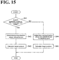
- the command generator 330 When the operation mode currently chosen is the movable coordinate system mode, the command generator 330 generates, based on an input on the operation screen 500 (which is dedicated to the movable coordinate system mode), a motion command for the leading end 12 in the second coordinate system C2. Specifically, upon execution of a point operation of specifying at least one point on the operation image 512, the command generator 330 determines a motion direction of the leading end 12 in the second coordinate system C2 such that the motion direction is correlated with a positional relationship between the one point and a reference point on the operation image 512; determines a motion scalar quantity of the leading end 12 such that the motion scalar quantity is correlated with the distance between the one point and the reference point; and generates a motion command for the leading end 12 such that the motion command includes the motion direction and the motion scalar quantity.
- scalar quantity refers to a quantity associated with a motion.
- examples of the motion scalar quantity include, but are not limited to: the speed at which the leading end 12 moves; the amount of a motion pitch; and the amount of acceleration.
- the command generator 330 includes a first movement command generator 331 and a second movement command generator 332, as more meticulously segmented functional modules.
- the first movement command generator 331 generates, based on an input on the first movement tool image 521, a movement command for the leading end 12 along the reference axis RL (for example, the Z axis C23).
- the first movement command generator 331 determines the movement direction such that on the movement line ML3, which corresponds to the one-dimensional operation system 530, the movement direction is correlated with a positional relationship between the one point and the reference point 531 of the one-dimensional operation system 530; determines the motion scalar quantity such that on the movement line ML3, the motion scalar quantity is correlated with the distance between the one point and the reference point 531; and generates the movement command such that on the movement line ML3, the movement command includes the movement direction and the motion scalar quantity.
- the first movement command generator 331 determines the movement direction such that on the movement line ML3, which corresponds to the one-dimensional operation system 530, the movement direction is correlated with a positional relationship between the point area and the reference point 531; and determines the motion scalar quantity such that on the movement line ML3, the motion scalar quantity is correlated with the distance between the point area and the reference point 531.
- the second movement command generator 332 generates, based on an operation input on the second movement tool image 522, a movement command for the leading end 12 in the second coordinate system C2 along an axis orthogonal to the reference axis RL (for example, the X axis C21 and the Y axis C22).
- the second movement command generator 332 determines the movement direction such that on the movement line corresponding to the one-dimensional operation system, the movement direction is correlated with a positional relationship between the one point and a reference point in the one-dimensional operation system; and determines the motion scalar quantity by which the leading end 12 moves such that on the movement line corresponding to the one-dimensional operation system, the motion scalar quantity is correlated with the distance between the one point and the reference point.
- the second movement command generator 332 determines the movement direction such that on the movement line ML1, which corresponds to the one-dimensional operation system 540, the movement direction is correlated with a positional relationship between the point area and the reference point 542; and determines the motion scalar quantity by which the leading end 12 moves such that on the movement line ML1, the motion scalar quantity is correlated with the distance between the point area and the reference point 542.
- the second movement command generator 332 determines the movement direction such that on the movement line ML2, which corresponds to the one-dimensional operation system 550, the movement direction is correlated with a positional relationship between the point area and the reference point 542; and determines the motion scalar quantity by which the leading end 12 moves such that the motion scalar quantity is correlated with the distance between the point area and the reference point 542.
- the operation screen may further include the quantity setting tool image 610.
- the first movement command generator 331 and the second movement command generator 332 may determine the motion scalar quantity included in the movement command based on an input on the quantity setting tool image 610.
- the first movement command generator 331 and the second movement command generator 332 determine the movement direction of the leading end 12 based on a point operation of specifying the point area 533, 534, 543, 544, 553, or 554.
- the first movement command generator 331 and the second movement command generator 332 may obtain, from the posture calculator 322, the turning angle of the operation inputter 311 about an axis perpendicular to the one axis. Then, based on the turning angle of the operation inputter 311 that has been obtained, the first movement command generator 331 and the second movement command generator 332 may determine the motion scalar quantity included in the movement command.
- the operation screen may further include the first turning tool image 523 and the second turning tool image 524.
- the command generator 330 may generate, based on an input on the first turning tool image 523 and the second turning tool image 524, a turning command for the leading end 12 in the second coordinate system C2.
- the command generator 330 may further include a first turning command generator 333 and a second turning command generator 334.
- the first turning command generator 333 generates, based on an input on the first turning tool image 523, a turning command for the leading end 12 about the reference axis RL (for example, the Z axis C23).
- the first turning command generator 333 determines the turning direction such that the motion direction is correlated with a positional relationship between the one point and the drawn line 532 about the movement line ML3, which corresponds to the uni-axis operation system 570.
- the first turning command generator 333 determines the turning direction of the leading end 12 about the movement line ML3, which corresponds to the uni-axis operation system 570.
- the second turning command generator 334 generates, based on an operation input on the second turning tool image 524, a turning command for the leading end 12 about an axis orthogonal to the reference axis RL (for example, the X axis C21 and the Y axis C22). Specifically, upon execution of a point operation of specifying at least one point in one of the uni-axis operation systems 580 and 590, the second turning command generator 334 determines the turning direction such that the turning direction is correlated with a positional relationship between the one point and the drawn line of the uni-axis operation system about the movement line corresponding to the uni-axis operation system.
- the second turning command generator 334 determines the turning direction such that the turning direction is correlated with a positional relationship between the point area and the drawn line 541 about the movement line ML1, which corresponds to the uni-axis operation system 580.
- the second turning command generator 334 determines the turning direction such that the turning direction is correlated with a positional relationship between the point area and the drawn line 551 about the movement line ML2, which corresponds to the uni-axis operation system 590.
- the command converter 341 converts the motion command into a first-coordinate-system motion command (for the leading end 12 in the first coordinate system C1). Specifically, the command convertor 341 calculates the first-coordinate-system motion command (for the leading end 12 in the first coordinate system C1)by multiplying the motion command for the leading end 12 in the second coordinate system C2 by a turning matrix that corresponds to the turning angle of the second coordinate system C2 relative to the first coordinate system C1.
- the command outputter 342 outputs, to the inverse kinematics operator 213 of the controller 200, a control command for controlling the robot 10 based on the first-coordinate-system motion command.
- the controller 200 includes circuitry 290.
- the circuitry 290 includes at least one processor 291, a memory 292, a storage 293,a driver 294, and a communication port 295.
- the storage 293 is a computer-readable non-volatile storage medium (non-limiting examples include a hard disc and a flash memory).
- the storage 293 stores programs for implementing the functional modules of the controller 200.
- the memory 292 temporarily stores programs loaded from the storage 293 and stores results of operations performed by the processor 291.
- the processor 291 cooperates with the memory 292 to execute the programs, thereby implementing the functional modules of the controller 200.
- the driver 294, at a command from the processor 291, outputs drive power to the actuators 41 to 46.
- the communication port 295 at a command from the processor 291, performs network communication with the operation device 300.
- the operation device 300 includes the touch panel 381, the posture sensor 382, and circuitry 390.
- the circuitry 390 includes at least one processor 391, a memory 392, a storage 393,an input/output port 394, and a communication port 395.
- the storage 393 is a computer-readable non-volatile storage medium (a non-limiting example is a flash memory).
- the storage 393 stores a program for causing the operation device 300 to perform a control method including: outputting screen data to the operation inputter 311 so that the operation inputter 311 displays an operation screen including at least one operation image 512; detecting the posture of the operation inputter 311 in the first coordinate system C1, which is used to control the robot 10; turning the second coordinate system C2, which is turnable relative to the first coordinate system C1, based on the posture of the operation inputter 311; upon execution of a point operation of specifying at least one point on the operation image 512, determining the motion direction of the leading end 12 in the second coordinate system C2 such that the motion direction is correlated with a positional relationship between the one point and the reference point 531 in the operation image 512 and/or a positional relationship between the one point and the reference point 542 in the operation image 512, determining the motion scalar quantity by which the leading end 12 moves such that the motion scalar quantity is correlated with the distance between the one point and the reference point 531 and the distance between the one
- the storage 393 may store a program for causing the operation device 300 to perform a control method including: detecting the posture of the operation inputter 311 in the first coordinate system C1, which is used to control the robot 10; turning the second coordinate system C2, which is turnable relative to the first coordinate system C1, based on the posture of the operation inputter 311; based on an operation input into the operation inputter 311, generating a motion command for the leading end 12 in the second coordinate system C2; converting the motion command for the leading end 12 in the second coordinate system C2 into a first-coordinate-system motion command for the leading end 12 in the first coordinate system C1; outputting a control command for controlling the robot 10 based on the first-coordinate-system motion command; and regulating the turning of the second coordinate system C2 about at least one axis.
- the storage 393 stores programs for implementing the functional modules of the operation device 300.
- the memory 392 temporarily stores programs loaded from the storage 393 and stores results of operations performed by the processor 391.
- the processor 391 cooperates with the memory 392 to execute the programs, thereby implementing the functional modules of the operation device 300.
- the input/output port 394 at a command from the processor 391, obtains signals from the touch panel 381 and the posture sensor 382, and outputs the signals to the touch panel 381.
- the communication port 395 at a command from the processor 291, performs network communication with the controller 200.
- This control procedure includes: detecting the posture of the operation inputter 311 in the first coordinate system C1, which is used to control the robot 10; turning the second coordinate system C2, which is turnable relative to the first coordinate system C1, based on the posture of the operation inputter 311; upon execution of a point operation of specifying at least one point on the operation image 512, determining the motion direction of the leading end 12 in the second coordinate system C2 such that the motion direction is correlated with a positional relationship between the one point and the reference point 531 in the operation image 512 and/or a positional relationship between the one point and the reference point 542 in the operation image 512, determining the motion scalar quantity by which the leading end 12 moves such that the motion scalar quantity is correlated with the distance between the one point and the reference point 531 and the distance between the one point and the reference point 542, and generating a motion command for the leading end 12 such that the motion
- This control procedure may include: turning the second coordinate system C2, which is turnable relative to the first coordinate system C1, based on the posture of the operation inputter 311; based on an operation input into the operation inputter 311, generating a motion command for the leading end 12 in the second coordinate system C2; converting the motion command for the leading end 12 in the second coordinate system C2 into a first-coordinate-system motion command for the leading end 12 in the first coordinate system C1; outputting a control command for controlling the robot 10 based on the first-coordinate-system motion command; and regulating the turning of the second coordinate system C2 about at least one axis.
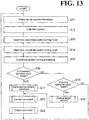
- control procedure is divided into: a screen data outputting procedure (procedure for outputting screen data of an operation screen); a control command outputting procedure in the movable coordinate system mode (procedure for outputting a control command from the operation device 300 to the controller 200); a calibration procedure (procedure for performing a calibration); and a procedure for performing control (procedure for performing control based on a control command).
- the operation device 300 performs steps S01, S02, and S03.
- the screen outputter 313 obtains model data of an initial operation screen from the model data storage 314. In this regard, which operation screen to use as the initial screen is set in advance.
- the screen outputter 313 outputs screen data to the operation inputter 311 so that the operation inputter 311 displays the operation screen.
- the input content identifier 312 checks whether the operation inputter 311 has received an operation input for changing the operation mode. Specifically, the input content identifier 312 checks whether there has been a point operation of pressing the input mode switch button 411 or 515.
- step S03 When at step S03 there has been an operation input for changing the operation mode, the operation device 300 performs step S04.
- the screen outputter 313 obtains model data of an operation screen corresponding to the changed operation mode.
- the operation device 300 performs steps S05 and S06.
- the operation device 300 performs steps S05 and S06 without performing step S04.
- the angle information obtainer 316 obtains status information indicating the current angles of the joints 31, 32, 33, 34, 35, and 36 from the control executor 214 of the controller 200.
- the input content identifier 312 checks whether there has been an operation input on the operation screens 400 and 500.
- step S07 the input content identifier 312 checks the content of the operation input that has been made. Specifically, when the position specified by the point operation coincides with the position of any one point area in the operation image 512, the input content identifier 312 determines that an operation of specifying the point area has been made. Then, the input content identifier 312 stores the determination result in the input content storage 317.
- the operation device 300 performs steps S08 and S09.
- the operation device 300 performs steps S08 and S09 without performing step S07.
- the screen outputter 313 adjusts the screen data of the operation screen based on information such as: the state of the operation input that has been made in the operation inputter 311; and status information indicating the current angles of the joints 31, 32, 33, 34, 35, and 36. Specifically, the screen outputter 313 highlights a particular portion (for example, a point area) of the operation screen corresponding to the point operation.
- the screen outputter 313 updates the data displayed on the angle indicator 513 based on the status information indicating the current angles of the joints 31, 32, 33, 34, 35, and 36.
- the screen outputter 313 outputs the screen data of the operation screen to the operation inputter 311.
- the operation device 300 returns the processing to step S03. Later on, whether there has been an operation input into the operation inputter 311 is continuously monitored so that the screen outputter 313 outputs screen data of an operation screen to the operation inputter 311 upon execution of an operation input.
- the operation device 300 performs steps S11, S12, S13, S14, S15, and S16.
- the posture calculator 322 obtains, from the device posture detector 321, information indicating the posture of the operation inputter 311 in the first coordinate system C1.
- the posture calculator 322 calculates the posture of the operation inputter 311 based on the information obtained from the device posture detector 321.
- the mode switch 325 switches between the regulation mode and the free mode based on the input on the regulation mode setting image 511.
- the coordinate system turning regulator 324 determines the turning angle of the second coordinate system C2 to regulate the turning of the second coordinate system C2.
- the coordinate system turning regulator 324 sets the turning angles of the second coordinate system C2 about the X axis C11 and the Y axis C12 at zero angles, and sets the turning angle of the operation inputter 311 about the Z axis C13 calculated by the posture calculator 322 at the turning angle of the second coordinate system C2 about the Z axis C13.
- the coordinate system turner 323 performs coordinate system turning processing of turning the second coordinate system C2 based on the turning angles determined by the coordinate system turning regulator 324.
- the command generator 330 check whether there has been an operation input on the first movement tool image 521 or the second movement tool image 522.
- step S17 When at step S16 there has been an operation input on the first movement tool image 521 or the second movement tool image 522, the operation device 300 performs step S17.
- the first movement command generator 331 or the second movement command generator 332 generates a movement command for the leading end 12 in the second coordinate system C2. Details of the processing at step S17 will be described later.
- step S16 When at step S16 there has been no operation input on the first movement tool image 521 or the second movement tool image 522, the operation device 300 performs step S18.
- step S18 the command generator 330 checks whether there has been an operation input on the first turning tool image 523 or the second turning tool image 524.
- step S19 When at step S18 there has been an operation input on the first turning tool image 523 or the second turning tool image 524, the operation device 300 performs step S19.
- the first turning command generator 333 or the second turning command generator 334 determines the turning direction of the leading end 12. Details of the processing at step S19 will be described later.
- step S21 the command convertor 341 converts the motion command for the leading end 12 in the second coordinate system C2 generated at step S17 or step S19 into a first-coordinate-system motion command for the leading end 12 in the first coordinate system C1.
- step S22 the command outputter 342 outputs the first-coordinate-system motion command (for the leading end 12 in the first coordinate system C1) obtained at step S21.
- the operation device 300 After step S22, the operation device 300 returns the processing to step S11. The operation device 300 also returns the processing to step S11 when there has been no operation input at step S18. Later on, whether there has been an operation input on the first movement tool image 521, the second movement tool image 522, the first turning tool image 523, and the second turning tool image 524 is continuously monitored so that the operation device 300 outputs a control command to the controller 200 upon execution of an operation input.
- step S31 the command generator 330 check whether there has been a point operation on the first movement tool image 521.
- the operation device 300 When at step S31 there has been a point operation on the first movement tool image 521, the operation device 300 performs steps S32, S33, and S34.
- the first movement command generator 331 determines the movement direction of the leading end 12 as a direction along the reference axis RL. For example, when the point area 533A or 533B has been specified by a point operation, the first movement command generator 331 determines the movement direction of the leading end 12 as the positive direction of the Z axis C23.
- the point area 534A or 534B has been specified by a point operation, the first movement command generator 331 determines the movement direction of the leading end 12 as the negative direction of the Z axis C23.
- the first movement command generator 331 determines the motion scalar quantity by which the leading end 12 moves. For example, when the point area 533B or 534B has been specified by a point operation, the first movement command generator 331 determines the motion scalar quantity as a higher value than when the point area 533A or 534A has been specified.
- the first movement command generator 331 calculates a post-movement target position of the leading end 12 based on the movement direction determined at step S32 and based on the motion scalar quantity determined at step S33.
- step S35 the second movement command generator 332 determines the movement direction of the leading end 12 along a surface perpendicular to the reference axis RL. For example, when the point area 543A, 543B, or 543C has been specified by a point operation, the second movement command generator 332 determines the movement direction of the leading end 12 as the positive direction of the X axis C21.
- the second movement command generator 332 determines the movement direction of the leading end 12 as the negative direction of the X axis C21.
- the second movement command generator 332 determines the movement direction of the leading end 12 as the positive direction of the Y axis C22.
- the second movement command generator 332 determines the movement direction of the leading end 12 as the negative direction of the Y axis C22.
- the operation device 300 performs steps S36 and S37.
- the second movement command generator 332 determines the motion scalar quantity by which the leading end 12 moves. For example, the point areas 543B and 544B are farther away from the reference point 542 than the point areas 543A and 544A are from the reference point 542, and when the point area 543B or 544B has been specified, the second movement command generator 332 determines the motion scalar quantity as a higher value than when the point area 543A or 544A has been specified.
- the point areas 543C and 544C are farther away from the reference point 542 than the point areas 543B and 544B are from the reference point 542, and when the point area 543C or 544C has been specified, the second movement command generator 332 determines the motion scalar quantity as an even higher value than when the point area 543B or 544B has been specified.
- the second movement command generator 332 calculates a post-movement target position of the leading end 12 based on the movement direction determined at step S35 and based on the motion scalar quantity determined at step S36.
- the operation device 300 ends the procedure for generating a movement command.
- step S41 the command generator 330 checks whether there has been a point operation on the first turning tool image 523.
- the operation device 300 When at step S41 there has been a point operation on the first turning tool image 523, the operation device 300 performs steps S42 and S43.
- the first turning command generator 333 determines the turning direction of the leading end 12 about the reference axis RL. For example, when one point in the uni-axis operation system 570 has been specified, the first turning command generator 333 determines the turning direction of the leading end 12 about the movement line ML3, which corresponds to the uni-axis operation system 570, based on whether the point area 571 or 572 has been specified.
- the first turning command generator 333 calculates a post-turning target position of the leading end 12 based on the turning direction determined at step S42.
- the operation device 300 When at step S41 there has been a point operation on the second turning tool image 524 (instead of the first turning tool image 523), the operation device 300 performs steps S44 and S45.
- the second turning command generator 334 determines the turning direction of the leading end 12 about an axis orthogonal to the reference axis RL. For example, when one point in the uni-axis operation system 580 has been specified, the second turning command generator 334 determines the turning direction of the leading end 12 about the movement line ML1, which corresponds to the uni-axis operation system 580, based on whether the point area 581 or 582 has been specified.
- the second turning command generator 334 determines the turning direction of the leading end 12 about the movement line ML2, which corresponds to the uni-axis operation system 590, based on whether the point area 591 or 592 has been specified.
- the second turning command generator 334 calculates a post-turning target position of the leading end 12 based on the turning direction determined at step S44.
- the operation device 300 ends the procedure for generating a turning command for the leading end 12.
- the operation device 300 performs steps S51 and S52.
- step S51 at the time of activation of the robot system 1, the unsetting notifier 352 sets the posture of the second coordinate system C2 at an initial posture. In other words, the unsetting notifier 352 performs a temporary calibration.
- step S52 the calibrator 351 checks whether there has been a point operation on the calibration button 514.
- the operation device 300 performs step S53.
- the calibrator 351 performs a calibration. That is, the calibrator 351 sets the posture of the second coordinate system C2 relative to the first coordinate system C1 at a preset initial posture. Specifically, the calibrator 351 makes the X axis C21, the Y axis C22, and the Z axis C23 respectively coincide with the X axis C11, the Y axis C12, and the Z axis C13.
- the operation device 300 After step S53, the operation device 300 returns the processing to step S52.
- the operation device 300 also returns the processing to step S52 when at step S52 the calibrator 351 has determined that there has been no point operation on the calibration button 514. Later on, the operation device 300 continuously monitors whether there has been a point operation on the calibration button 514 so that the operation device 300 performs a calibration upon execution of a point operation on the calibration button 514.
- the controller 200 performs steps S61, S62, and S63.
- the inverse kinematics operator 213 waits for a control command to be obtained from the command outputter 342 of the operation device 300.
- the inverse kinematics operator 213 performs an inverse kinematics operation to calculate joint angle target values for moving the leading end 12.
- the control executor 214 controls the robot 10 to drive the joints 31, 32, 33, 34, 35, and 36 based on the joint angle target values using the actuators 41, 42, 43, 44, 45, and 46. Later on, the controller 200 calculates joint angle target values upon receipt of a control command from the operation device 300, and controls the robot 10 based on the joint angle target values.
- the operation device 300 includes the operation inputter 311, the screen outputter 313, the device posture detector 321, the coordinate system turner 323, the command generator 330, the command convertor 341, and the command outputter 342.
- the robot 10 is operated.
- the robot 10 includes the leading end 12, the base 11, and the multi-articular arm 20.
- the multi-articular arm 20 changes the position and the posture of the leading end 12 relative to the base 11.
- the screen outputter 313 outputs screen data to the operation inputter 311 so that the operation inputter 311 displays the operation screens 500, 501, 502, and 503, each of which includes at least one operation image 512.
- the operation image 512 is used to input a motion command for the leading end 12.
- the device posture detector 321 detects the posture of the operation inputter 311 in the first coordinate system C1, which is used to control the robot 10. Based on the posture of the operation inputter 311, the coordinate system turner 323 turns the second coordinate system C2, which is turnable relative to the first coordinate system C1.
- the command generator 330 determines the motion direction of the leading end 12 in the second coordinate system C2 such that the motion direction is correlated with a positional relationship between the one point and the reference point 531 in the operation image 512 and/or a positional relationship between the one point and the reference point 542 in the operation image 512; determines the motion scalar quantity by which the leading end 12 moves such that the motion scalar quantity is correlated with the distance between the one point and the reference point 531 and the distance between the one point and the reference point 542; and generates a motion command for the leading end 12 such that the motion command includes the motion direction and the motion scalar quantity.
- the command convertor 341 converts the motion command for the leading end 12 into a first-coordinate-system motion command for the leading end 12 in the first coordinate system C1.
- the command outputter 342 outputs a control command for controlling the robot 10 based on the first-coordinate-system motion command.
- the command generator 330 determines both the movement direction and the motion scalar quantity based on the position of a point specified by a point operation (this point will be hereinafter referred to as "specified point"). With the configuration described so far, the operation device 300 effectively improves manipulability associated with teaching of robots.
- the movement direction is set such that the movement direction is correlated with a positional relationship between the specified point and the reference point 531 and/or a positional relationship between the specified point and the reference point 542.
- the motion scalar quantity is set such that the motion scalar quantity is correlated with the distance between the specified point and the reference point 531 and/or the distance between the specified point and the reference point 542.
- the above-described configuration is effective for a further improvement of manipulability associated with teaching of robots. It is to be noted that an input by a point operation minimizes the discrepancy between the content of input intended by the operator and the content that has actually been input, as compared with an input by a slide operation. This configuration is effective for improving manipulability associated with teaching of robots. It is to be noted that the motion scalar quantity may include the speed at which the leading end 12 moves.
- the at least one operation image 512 may include the first movement tool image 521 and the second movement tool image 522. On the first movement tool image 521 and the second movement tool image 522, a command for moving the leading end 12 is input.
- the first movement tool image 521 may include at least one one-dimensional operation systems 530.
- the one-dimensional operation systems 530 is drawn along the one drawn line 532.
- the second movement tool image 522 may include at least one one-dimensional operation system 540 or 550.
- the one-dimensional operation system 540 is drawn along the one drawn line 541, and the one-dimensional operation system 550 is drawn along the one drawn line 551.
- the one-dimensional operation system 530 corresponds to the movement line ML3, which is set in the second coordinate system C2; the one-dimensional operation system 540 corresponds to the movement line ML1, which is set in the second coordinate system C2; and the one-dimensional operation system 550 corresponds to the movement line ML2, which is set in the second coordinate system C2.
- the command generator 330 may include the first movement command generator 331 and the second movement command generator 332. Based on an input the first movement tool image 521 and the second movement tool image 522, the first movement command generator 331 and the second movement command generator 332 generate a movement command for the leading end 12 in the second coordinate system C2.
- the first movement command generator 331 and the second movement command generator 332 may: determine the movement direction of the leading end 12 such that the movement direction is correlated with a positional relationship between the one point and the reference point 531 of the one-dimensional operation system 530 on the movement line ML3, which corresponds to the one-dimensional operation system 530, such that the movement direction is correlated with a positional relationship between the one point and the reference point 542 of the one-dimensional operation system 540 on the movement line ML1, which corresponds to the one-dimensional operation system 540, and such that the movement direction is correlated with a positional relationship between the one point and the reference point 542 of the one-dimensional operation system 550 on the movement line ML2, which corresponds to the one-dimensional operation system 550; determine the motion scalar quantity of the leading end 12 such that the motion scalar quantity is correlated with the distance between the one point and the reference point 531, and such that the motion s
- the one-dimensional operation system 530 of the operation image 512 corresponds to the movement line ML3 in the second coordinate system C2
- the one-dimensional operation system 540 of the operation image 512 corresponds to the movement line ML1 in the second coordinate system C2
- the one-dimensional operation system 550 of the operation image 512 corresponds to the movement line ML2 in the second coordinate system C2.
- the second movement tool image 522 may include at least one one-dimensional operation system 540 or 550.
- the one-dimensional operation systems 540 and 550 are respectively drawn along the drawn lines 541 and 551, which cross each other.
- the one-dimensional operation systems 540 and 550 respectively correspond to the movement lines ML1 and ML2, which cross each other in the second coordinate system C2.
- the second movement command generator 332 may: determine the movement direction such that the movement direction is correlated with a positional relationship between the one point and the reference point 542 of the one-dimensional operation system 540 or 550 on the movement line ML1 or ML2, which respectively correspond to the one-dimensional operation systems 540 and 550; and determine the motion scalar quantity such that the motion scalar quantity is correlated with the distance between the one point and the reference point 542. This enables the operator to clearly recognize the direction in which the leading end 12 is moving while ensuring that a wider variety of movement directions can be specified on one operation image 512.
- the at least one one-dimensional operation system 530 may include the plurality of point areas 533A, 533B, 534A, and 534B.
- the point areas 533A, 533B, 534A, and 534B are aligned in an order from the reference point 531.
- the at least one one-dimensional operation system 540 may include the plurality of point areas 543A, 543B, 543C, 544A, 544B, and 544C.
- the point areas 543A, 543B, 543C, 544A, 544B, and 544C are aligned in an order from the reference point 542.
- the at least one one-dimensional operation system550 may include the plurality of point areas 553A, 553B, 553C, 554A, 554B, and 554C.
- the point areas 553A, 553B, 553C, 554A, 554B, and 554C are aligned in an order from the reference point 542.
- the first movement command generator 331 and the second movement command generator 332 may: determine the movement direction such that the movement direction is correlated with a positional relationship between the point area and the reference point 531 on the movement line ML3, which corresponds to the one-dimensional operation system 530, such that the movement direction is correlated with a positional relationship between the point area and the reference point 542 on the movement line ML1, which corresponds to the one-dimensional operation system 540, and such that the movement direction is correlated with a positional relationship between the point area and the reference point 542 on the movement line ML2, which corresponds to the one-dimensional operation system 550; determine the motion scalar quantity such that the motion scalar quantity is correlated with the distance between the point area and the reference point 531, and such that the motion scalar quantity is correlated with the distance between the point area and the reference point 542.
- the at least one one-dimensional operation system 530 may include the dead areas 535 between the point areas 533A, 533B, 534A, and 534B. In the dead areas 535, point operations are disregarded.
- the at least one one-dimensional operation system 540 may include the dead areas 545 between the point areas 543A, 543B, 543C, 544A, 544B, and 544C. In the dead areas 545, point operations are disregarded.
- the at least one one-dimensional operation system 550 may include the dead areas 555 between the point areas 553A, 553B, 553C, 554A, 554B, and 554C. In the dead areas 555, point operations are disregarded.
- the dead areas 535, 545, and 555 are provided between the point areas. This eliminates or minimizes erroneous choosing of point areas, resulting in a further improvement of manipulability associated with teaching of robots.
- the widths W1 of the point areas 533A and 534A and the widths W2 of the point areas 533B and 534B may increase as the point areas are farther away from the reference point 531.
- the widths W11 of the point areas 543A and 544A, the widths W12 of the point areas 543B and 544B, and the widths W13 of the point areas 543C and 544C may increase as the point areas are farther away from the reference point 542.
- the widths W21 of the point areas 553A and 554A, the widths W22 of the point areas 553B and 554B, and the widths W23 of the point areas 553C and 554C may increase as the point areas are farther away from the reference point 542. This enables the operator to more intuitively recognize the point areas in relation to their scalar quantities.
- the at least one operation image 512 may further include the first turning tool image 523 and the second turning tool image 524. On the first turning tool image 523 and the second turning tool image 524, a turning command for the leading end 12 is input.
- the command generator 330 may further include the first turning command generator 333 and the second turning command generator 334.
- the first turning command generator 333 and the second turning command generator 334 generate, based on an input on the first turning tool image 523 and the second turning tool image 524, a turning command for the leading end 12 in the second coordinate system C2. This ensures that the posture of the leading end 12 as well can be specified in the second coordinate system C2.
- this configuration is effective for a further improvement of manipulability associated with teaching of robots.
- the multi-articular arm 20 may include the plurality of joints 31, 32, 33, 34, 35, and 36.
- the screen outputter 313 may output screen data to the operation inputter 311 so that the operation inputter 311 displays operation screens 500, 501, 502, and 503.
- the operation screens 500, 501, 502, and 503 each include the angle indicator 513.
- the angle indicator 513 indicates a combination of an angle status and an angle limit of each of the plurality of joints 31, 32, 33, 34, 35, and 36. This provides the operator with a knowledge of the movable limit of the robot 10 in making an operation. Thus, this configuration is effective for a further improvement of manipulability associated with teaching of robots.
- the operation device 300 may further include the calibrator 351 and the unsetting notifier 352.
- the calibrator 351 performs, based on an input into the operation inputter 311, a calibration of setting the posture of the second coordinate system C2 relative to the first coordinate system C1 at a preset initial posture.
- the unsetting notifier 352 notifies that no calibration has been performed by the calibrator 351. This more reliably provides the operator with a manipulability that is adapted to the sense of orientation of the operator.
- the operation device 300 includes the operation inputter 311, the device posture detector 321, the coordinate system turner 323, the command generator 330, the command convertor 341, the command outputter 342, and the coordinate system turning regulator 324.
- the robot 10 is operated.
- the robot 10 includes the leading end 12, the base 11, and the multi-articular arm 20.
- the multi-articular arm 20 changes the position and the posture of the leading end 12 relative to the base 11.
- the device posture detector 321 detects the posture of the operation inputter 311 in the first coordinate system C1, which is used to control the robot 10. Based on the posture of the operation inputter 311, the coordinate system turner 323 turns the second coordinate system C2, which is turnable relative to the first coordinate system C1.
- the command generator 330 Based on an operation input into the operation inputter 311, the command generator 330 generates a motion command for the leading end 12 in the second coordinate system C2.
- the command convertor 341 converts the motion command for the leading end 12 in the second coordinate system C2 into a first-coordinate-system motion command for the leading end 12 in the first coordinate system C1.
- the command outputter 342 outputs a control command for controlling the robot 10 based on the first-coordinate-system motion command.
- the coordinate system turning regulator 324 regulates the turning of the second coordinate system C2 about at least one axis.
- the operation device 300 enables the operator to input a movement command for the leading end 12 in the second coordinate system C2, which is turnable based on the posture of the operation inputter 311. This enables the operator to make an operation input that is adapted to the sense of orientation of the operator. Also in this above configuration, the turning direction of the second coordinate system C2 based on the posture of the operation inputter 311 is limited. This eliminates or minimizes an excessive amount of turning of the second coordinate system C2. This, in turn, eliminates or minimizes the discrepancy between an operation input and the sense of orientation of the operator, which can otherwise be caused by an excessive amount of turning of the second coordinate system C2. Thus, the operation device 300 is effective for improving manipulability associated with teaching of robots.
- the coordinate system turning regulator 324 may regulate the turning of the second coordinate system C2 about an axis perpendicular to the reference axis RL, which extends in one direction, while allowing the turning of the second coordinate system C2 about the reference axis RL. This imposes an additional restriction on the operator in turning the second coordinate system C2 so that the second coordinate system C2 is prevented from turning excessively. Thus, this configuration is further effective for improving manipulability associated with teaching of robots.
- the reference axis RL may be a vertical axis.
- a vertical direction can be universal in the sense of orientation of the operator, while the front and rear directions and the right and left directions can vary depending on the orientation of the operator.
- the reference axis RL is set at a vertical direction. This ensures an operation input that is more reliably adapted to the sense of orientation of the operator.
- the operation device 300 may further include the screen outputter 313.
- the screen outputter 313 outputs screen data to the operation inputter 311 so that the operation inputter 311 displays the operation screens 500, 501, and 503.
- the operation screens 500, 501, and 503 include the first movement tool image 521 and the second movement tool image 522.
- On the first movement tool image 521 a command for moving the leading end 12 along the reference axis RL is input.
- On the second movement tool image 522 a command for moving the leading end 12 along a surface perpendicular to the reference axis RL is input.
- the command generator 330 may include the first movement command generator 331 and the second movement command generator 332.
- the first movement command generator 331 Based on an operation input on the first movement tool image 521, the first movement command generator 331 generates a movement command for the leading end 12 in the second coordinate system C2. Based on an operation input on the second movement tool image 522, the second movement command generator 332 generates a movement command for the leading end 12 in the second coordinate system C2.
- the tool image is varied depending on whether the movement command is a movement command for a movement along an axis (the reference axis RL) that remains unchanged even if the posture of the operation inputter 311 changes or a movement command for a movement along an axis that is turnable based on the posture of the operation inputter 311. This ensures an operation input that is more reliably adapted to the sense of orientation of the operator.
- the first movement command generator 331 may determine, based on the position of the one point on the first movement tool image 521, the movement direction in which the leading end 12 moves along the reference axis RL.
- the second movement command generator 332 may determine, based on the position of the one point on the second movement tool image 522, the movement direction in which the leading end 12 moves along a surface perpendicular to the reference axis RL.
- An input by a point operation minimizes the discrepancy between the content of input intended by the operator and the content that has actually been input, as compared with an input by a slide operation.
- this configuration is further effective for improving manipulability associated with teaching of robots.
- the above configuration also ensures that a one-dimensional operation input is used to input a movement command for a movement along the reference axis RL, and a two-dimensional operation input is used to input a movement command for a movement along a surface perpendicular to the reference axis RL. This ensures an input that is more reliably adapted to the sense of orientation of the operator.
- the first movement tool image 521 may include the one-dimensional operation system 530.
- the one-dimensional operation system 530 is drawn along the one drawn line 532.
- the one-dimensional operation system 530 corresponds to the one movement line ML3, which is set along the reference axis RL in the second coordinate system C2.
- the second movement tool image 522 may include the one-dimensional operation systems 540 and 550.
- the one-dimensional operation systems 540 and 550 are respectively drawn along the drawn lines 541 and 551, which cross each other.
- the one-dimensional operation systems 540 and 550 respectively correspond to the movement lines ML1 and ML2, which cross each other on a surface perpendicular to the reference axis RL in the second coordinate system C2.
- the first movement command generator 331 may determine the movement direction based on the position of the one point on the movement line ML3, which corresponds to the one-dimensional operation system 530.
- the second movement command generator 332 may determine the movement direction based on the position of the one point in the one-dimensional operation system 540 or 550 on the movement line ML1 or ML2, which respectively correspond to the one-dimensional operation systems 540 and 550. This enables the operator to more clearly recognize the movement direction of the leading end 12 on a surface perpendicular to the reference axis RL based on an operation input.
- the operation screen 503 may further include the quantity setting tool image 610.
- the quantity setting tool image 610 specifies the motion scalar quantity included in the movement command.
- the first movement command generator 331 and the second movement command generator 332 may determine the motion scalar quantity included in the movement command based on an input on the quantity setting tool image 610.
- the motion scalar quantity is input on an operation image different from the operation image 512. This prevents an excessive scalar quantity from being input.
- the operation screen 502 may further include the first turning tool image 523 and the second turning tool image 524. On the first turning tool image 523 and the second turning tool image 524, a turning command for the leading end 12 is input.
- the command generator 320 may further include the first turning command generator 333 and the second turning command generator 334. Based on an input on the first turning tool image 523 and the second turning tool image 524, the first turning command generator 333 and the second turning command generator 334 may generate a turning command for the leading end 12 in the second coordinate system C2. This ensures that the posture of the leading end 12 as well can be specified in the second coordinate system C2. Thus, this configuration is effective for a further improvement of manipulability associated with teaching of robots.
- the multi-articular arm 20 may include the plurality of joints 31, 32, 33, 34, 35, and 36.
- the screen outputter 313 may output screen data to the operation inputter 311 so that the operation inputter 311 displays operation screens 500, 501, 502, and 503.
- the operation screens 500, 501, 502, and 503 each include the angle indicator 513.
- the angle indicator 513 indicates a combination of an angle status and an angle limit of each of the plurality of joints 31, 32, 33, 34, 35, and 36. This provides the operator with a knowledge of the movable limit of the robot 10 in making an operation. Thus, this configuration is effective for a further improvement of manipulability associated with teaching of robots.
- the operation device 300 may further include the mode switch 325.
- the mode switch 325 switches between the regulation mode and the free mode. In the regulation mode, the coordinate system turning regulator 324 regulates the turning of the second coordinate system C2. In the free mode, the coordinate system turning regulator 324 does not regulate the turning of the second coordinate system C2. This provides greater flexibility to the needs of the operator.
- the operation device 300 may further include the calibrator 351 and the unsetting notifier 352. Based on an input into the operation inputter 311, the calibrator 351 sets the posture of the second coordinate system C2 relative to the first coordinate system C1 at a preset initial posture. When the initial posture has not been set by the calibrator 351, the unsetting notifier 352 notifies that the initial posture has not been set. This ensures a manipulability that is more reliably adapted to the sense of orientation of the operator.
- the operation device 300 may further include the posture calculator 322.
- the posture calculator 322 calculates, based on information detected by the device posture detector 321, the turning angle of the operation inputter 311 about an axis perpendicular to the one axis.
- the command generator 330 may determine the motion scalar quantity included in the motion command based on the turning angle of the operation inputter 311 about the axis perpendicular to the one axis. This ensures that the information of the posture of the operation inputter 311 is effectively utilized. Thus, this configuration is effective for a further improvement of manipulability associated with teaching of robots.
- Angle indicator 521 ... First movement tool image, 522 ... Second movement tool image, 530, 540, 550 ...
- One-dimensional operation system 531, 542 ... Reference point, 532, 541, 551 ... Drawn line, 533A, 533B, 534A, 534B, 543A, 543B, 543C, 544A, 544B, 544C, 553A, 553B, 553C, 554A, 554B, 554C ... Point area, 535, 545, 555 ... Dead area, C1 ... First coordinate system, C11 ... X axis, C12 ... Y axis, C13 ... Z axis, C2 ... Second coordinate system, C21 ...
Landscapes
- Engineering & Computer Science (AREA)
- Robotics (AREA)
- Mechanical Engineering (AREA)
- Physics & Mathematics (AREA)
- Automation & Control Theory (AREA)
- General Physics & Mathematics (AREA)
- Theoretical Computer Science (AREA)
- General Engineering & Computer Science (AREA)
- Fuzzy Systems (AREA)
- Mathematical Physics (AREA)
- Software Systems (AREA)
- Evolutionary Computation (AREA)
- Human Computer Interaction (AREA)
- Artificial Intelligence (AREA)
- Manipulator (AREA)
- Numerical Control (AREA)
Abstract
Description
- The present invention relates to an operation device, a control system, a control method, and a program.
-
JP 2011-224696A - The contents of
JP 2011-224696A - It is an object of the present invention to provide a control system that effectively improves manipulability associated with teaching of robots.
- According to one aspect of the present disclosure, an operation device includes an operation inputter, a screen outputter, a device posture detector, a coordinate system turner, a command generator, a command convertor, and a command outputter. The operation inputter is configured to operate a robot. The robot includes a leading end and a multi-articular arm configured to change a position and a posture of the leading end. The screen outputter is configured to output, to the operation inputter, at least one operation image on which a motion command for the leading end of the robot is input. The device posture detector is configured to detect a posture of the operation inputter in a first coordinate system that is for controlling the robot. The coordinate system turner is configured to, based on the posture of the operation inputter, turn a second coordinate system turnable relative to the first coordinate system. The command generator is configured to, upon execution of a point operation of specifying at least one point on the operation image, determine a motion direction of the leading end of the robot in the second coordinate system such that the motion direction is correlated with a positional relationship between the one point and a reference point on the operation image. The command generator is configured to determine a motion scalar quantity of the leading end of the robot such that the motion scalar quantity is correlated with a distance between the one point and the reference point. The command generator is configured to generate the motion command such that the motion command includes the motion direction and the motion scalar quantity. The command convertor is configured to convert the motion command into a first-coordinate-system motion command for the leading end of the robot in the first coordinate system. The command outputter is configured to output a control command for controlling the robot based on the first-coordinate-system motion command.
- According to another aspect of the present disclosure, a control system includes the above-described operation device and a controller. The controller is configured to, based on the control command, control the robot to move the leading end of the robot using the multi-articular arm.
- According to another aspect of the present disclosure, a control method is performed in an operation device for operating a robot that includes a leading end and a multi-articular arm configured to change a position and a posture of the leading end. The control method includes outputting at least one operation image to an operation inputter. A posture of the operation inputter in a first coordinate system that is for controlling the robot is detected. Based on the posture of the operation inputter, a second coordinate system turnable relative to the first coordinate system is turned. Upon execution of a point operation of specifying at least one point on the operation image: a motion direction of the leading end of the robot in the second coordinate system is determined such that the motion direction is correlated with a positional relationship between the one point and a reference point on the operation image; a motion scalar quantity of the leading end of the robot is determined such that the motion scalar quantity is correlated with a distance between the one point and the reference point; and a motion command for the leading end of the robot is generated. The motion command includes the motion direction and the motion scalar quantity. The motion command is converted into a first-coordinate-system motion command for the leading end of the robot in the first coordinate system. A control command for controlling the robot based on the first-coordinate-system motion command is output.
- According to the other aspect of the present disclosure, a program is for causing an operation device for operating a robot to perform a control method. The robot includes a leading end and a multi-articular arm configured to change a position and a posture of the leading end. The control method includes outputting at least one operation image to an operation inputter. A posture of the operation inputter in a first coordinate system that is for controlling the robot is detected. Based on the posture of the operation inputter, a second coordinate system turnable relative to the first coordinate system is turned. Upon execution of a point operation of specifying at least one point on the operation image: a motion direction of the leading end of the robot in the second coordinate system is determined such that the motion direction is correlated with a positional relationship between the one point and a reference point on the operation image; a motion scalar quantity of the leading end of the robot is determined such that the motion scalar quantity is correlated with a distance between the one point and the reference point; and a motion command for the leading end of the robot is generated. The motion command includes the motion direction and the motion scalar quantity. The motion command is converted into a first-coordinate-system motion command for the leading end of the robot in the first coordinate system. A control command for controlling the robot based on the first-coordinate-system motion command is output.
- The above-described embodiments of the present invention ensure a control system that effectively improves manipulability associated with teaching of robots.
- A more complete appreciation of the present invention and many of the attendant advantages thereof will be readily obtained as the same becomes better understood by reference to the following detailed description when considered in connection with the accompanying drawings, wherein:
-
FIG. 1 is a schematic illustrating an example configuration of a robot system; -
FIG. 2 is a block diagram illustrating an example functional configuration of a control system; -
FIG. 3 is a schematic illustrating an example operation screen in a fixed coordinate system mode; -
FIG. 4 is a schematic illustrating an example operation screen in a movable coordinate system mode; -
FIG. 5 is a schematic illustrating a modification operation screen in the movable coordinate system mode; -
FIG. 6 is a schematic illustrating another modification operation screen in the movable coordinate system mode; -
FIG. 7 is a schematic illustrating another modification operation screen in the movable coordinate system mode; -
FIG. 8 is a schematic illustrating an example posture of a touch panel; -
FIG. 9 is a schematic illustrating an example of coordinate system turning processing; -
FIG. 10 is a schematic illustrating an example of how a calibration-related element is arranged; -
FIG. 11 is a block diagram illustrating a hardware configuration of the control system; -
FIG. 12 is a flowchart of an example procedure for outputting screen data; -
FIG. 13 is a flowchart of an example procedure for operation control; -
FIG. 14 is a flowchart of an example procedure for movement command generation; -
FIG. 15 is a flowchart of an example procedure for rotation command generation; -
FIG. 16 is a flowchart of an example calibration procedure; and -
FIG. 17 is a flowchart of an example procedure for performing control. - The embodiments will now be described with reference to the accompanying drawings, wherein like reference numerals specifying corresponding or identical elements throughout the various drawings.
- A
robot system 1 according to this embodiment is a system that causes a robot to automatically repeat a motion taught in advance by an operator. There is no particular limitation to the application in which therobot system 1 is used. Example applications of therobot system 1 include, but are not limited to, industrial applications in which robots perform work such as machining, processing, and assembly work. - The
robot system 1 includes arobot 10 and acontrol system 100. In this embodiment, therobot 10 is a six-axis vertical multi-articular robot and includes a base 11, a leadingend 12, and amulti-articular arm 20. The base 11 is mounted or placed on a floor surface of a workspace of therobot 10. Themulti-articular arm 20 connects the base 11 and theleading end 12 to each other. - The
multi-articular arm 20 includes a plurality of joints. By changing the motion angles of the plurality of joints, themulti-articular arm 20 changes the position and the posture of theleading end 12 relative to the base 11. Themulti-articular arm 20 includes aturnable portion 21, afirst arm 22, a second arm 23, awrist 24, andactuators turnable portion 21 is mounted on an upper portion of the base 11 turnably about vertical axis Ax1. Specifically, themulti-articular arm 20 includes a joint 31. The joint 31 makes aturnable portion 21 turnable about the axis Ax1. - The
first arm 22 is connected to theturnable portion 21 swingably about axis Ax2, which crosses or is orthogonal to the axis Ax1. Specifically, themulti-articular arm 20 includes a joint 32. The joint 32 makes thefirst arm 22 swingable about the axis Ax2. It is to be noted that when axes "cross" each other, this means that the axes may be skew axes, as if the axes are in aligned in "grade separation" arrangement. The same applies in the following description. - The second arm 23 is connected to the base end of the
first arm 22 swingably about axis Ax3, which crosses the axis Ax1. Specifically, themulti-articular arm 20 includes a joint33. The joint33 makes the second arm 23 swingable about the axis Ax3. The axis Ax3 may be parallel to the axis Ax2. - The
wrist 24 includes aturnable arm 26 and a swingable arm 27. Theturnable arm 26 extends in the center of the second arm 23 and protrudes beyond the leading end of the second arm 23. Theturnable arm 26 is turnable about axis Ax4, which coincides with the center of the second arm 23. Specifically, themulti-articular arm 20 includes a joint 34. The joint 34 makes theturnable arm 26 turnable about the axis Ax4. The swingable arm 27 is connected to the leading end of theturnable arm 26 swingably about axis Ax5, which crosses or is orthogonal to the axis Ax4. Specifically, themulti-articular arm 20 includes a joint 35. The joint 35 makes the swingable arm 27 swingable about the axis Ax5. - The leading
end 12 is connected to the leading end of the swingable arm 27 turnably about axis Ax6, which coincides with the center of the swingable arm 27. Specifically, themulti-articular arm 20 includes a joint 36. The joint 36 makes theleading end 12 turnable about the axis Ax6. - The
actuators joints multi-articular arm 20. For example, theactuator 41 causes theturnable portion 21 to turn about the axis Ax1; the actuator 42 causes thefirst arm 22 to swing about the axis Ax2; the actuator 43 causes the second arm 23 to swing about the axis Ax3; the actuator 44 causes theturnable arm 26 to turn about the axis Ax4; theactuator 45 causes the swingable arm 27 to swing about the axis Ax5; and theactuator 46 causes the leadingend 12 to turn about axis Ax6. That is, theactuators 41 to 46 respectively drive thejoints 31 to 36. - It is to be noted that the above-described configuration of the
robot 10 has been presented for example purposes only; therobot 10 may have any other configuration insofar as therobot 10 is capable of changing the position and the posture of the leading end of therobot 10 relative to the base of therobot 10 using a multi-articular arm. For example, therobot 10 may be a seven-axis robot, with a redundant axis added to the above-described six-axis vertical multi-articular robot. Also, therobot 10 may be a "SCARA (Selective Compliance Assembly Robot Arm)" robot. - The
control system 100 is a system to control therobot 10, and includes acontroller 200 and anoperation device 300. Thecontroller 200 stores, in the form of motion programs, details of motions of therobot 10 taught by the operator, and controls therobot 10 based on the motion programs. Theoperation device 300 obtains an operation input made by the operator, generates a command that is based on the operation input, and outputs the command to thecontroller 200. An example configuration of thecontroller 200 and an example configuration of theoperation device 300 will be described in detail below. Controller - As illustrated in
FIG. 2 , thecontroller 200 performs: based on a motion program, controlling therobot 10 to move theleading end 12 using the multi-articular arm 20 (this control will be hereinafter referred to as "play mode control"); and, based on a control command from theoperation device 300, controlling therobot 10 to move theleading end 12 using the multi-articular arm 20 (this control will be hereinafter referred to as "teaching mode control"). For example, thecontroller 200 includes functional configurations (hereinafter referred to as "functional modules") such as amodel information storage 211, aprogram storage 212, aninverse kinematics operator 213, and acontrol executor 214. - The
model information storage 211 stores model information including the sizes of the elements of the robot 10 (for example, the lengths of thefirst arm 22, the second arm 23, theturnable arm 26, and the swingable arm 27). Theprogram storage 212 stores, in the form of motion programs, details of motions taught by the operator through theoperation device 300. Each motion program includes a plurality of motion commands aligned in time order. The motion commands include a movement command that specifies a target position and a target posture of theleading end 12 relative to the base 11. - The
inverse kinematics operator 213 performs an inverse kinematics operation to calculate joint angle target values (motion angle target values of thejoints end 12 based on the target position and the target posture of theleading end 12. In the teaching mode control, based on a target position and a target posture of theleading end 12 specified by the control command from theoperation device 300, theinverse kinematics operator 213 calculates joint angle target values for moving the leadingend 12. In the play mode control, theinverse kinematics operator 213 calculates joint angle target values for moving the leadingend 12 based on a target position and a target posture of theleading end 12 specified by the motion command of the motion program. - Based on the joint angle target values, the
control executor 214 controls themulti-articular arm 20 to drive thejoints actuators - When the
controller 200 performs the teaching mode control, theoperation device 300 generates a control command for causing therobot 10 to make a motion based on a motion-teaching operation input, and outputs the control command to thecontroller 200. Theoperation device 300 is a "tablet terminal", and includes atouch panel 381 and aposture sensor 382. - The touch panel 381 (operation inputter) is an input device made up of a display device with a contact position detection device superimposed on the display device. Examples of the display device include, but are not limited to, a liquid crystal monitor and an organic EL monitor. A non-limiting example of the contact position detection device is a touch pad. The
touch panel 381 receives an operation input in the form of a contact on the screen of the display device. - The posture sensor 382 (device posture detector) detects the posture of the operation device 300 (that is, the posture of the touch panel 381). A non-limiting example of the
posture sensor 382 is a gyro sensor. The gyro sensor detects changes in the posture of the operation device 300 (that is, changes in the posture of the touch panel 381) about three axes approximately orthogonal to each other. - The
operation device 300 performs: detecting, using theposture sensor 382, the posture of thetouch panel 381 in a first coordinate system C1, which is used to control therobot 10; turning a second coordinate system C2, which is turnable relative to the first coordinate system C1, based on the posture of the touch panel 381 (seeFIG. 9 ); based on an operation input on thetouch panel 381, generating a motion command for theleading end 12 in the second coordinate system C2; converting the motion command for theleading end 12 into a first-coordinate-system motion command for theleading end 12 in the first coordinate system C1; outputting a control command for controlling the robot based on the first-coordinate-system motion command 10. - The first coordinate system C1 may be any coordinate system with which the position and the posture of the
leading end 12 relative to the base 11 are uniquely determined. For example, the first coordinate system C1 is a coordinate system fixed to the base 11, and includes three coordinate axes (X axis C11, Y axis C12, and Z axis C13) approximately orthogonal to each other. The Z axis C13 is a vertical axis (perpendicular to a horizontal surface), and the upward direction of the Z axis C13 is the positive direction. - Similarly, the second coordinate system C2 includes three coordinate axes (X axis C21, Y axis C22, and Z axis C23) approximately orthogonal to each other. The turning angle of the second coordinate system C2 relative to the first coordinate system C1 is defined based on such an initial state that the X axis C21, the Y axis C22, and the Z axis C23 respectively coincide with the X axis C11, the Y axis C12, and the Z axis C13.
- The
operation device 300 may further perform: outputting screen data to thetouch panel 381 so that an operation screen including at least one operation image is displayed on thetouch panel 381. Upon execution of a point operation of specifying at least one point on the operation image, theoperation device 300 may perform: determining a motion direction of theleading end 12 in the second coordinate system C2 such that the motion direction is correlated with a positional relationship between the one point and a reference point on the operation image; determining a motion scalar quantity of theleading end 12 such that the motion scalar quantity is correlated with the distance between the one point and the reference point; and generating a motion command for theleading end 12 such that the motion command includes the motion direction and the motion scalar quantity. Theoperation device 300 may further perform: regulating turning of the second coordinate system C2 about at least one axis. - As functional modules for displaying an operation screen and for receiving an operation input, the
operation device 300 includes anoperation inputter 311, aninput content identifier 312, ascreen outputter 313, amodel data storage 314, ajoint information storage 315, anangle information obtainer 316, and aninput content storage 317. As functional modules for turning of the second coordinate system C2, theoperation device 300 includes adevice posture detector 321, aposture calculator 322, a coordinatesystem turner 323, a coordinatesystem turning regulator 324, amode switch 325, acalibrator 351, and anunsetting notifier 352. As functional modules for generation and output of a control command, theoperation device 300 includes acommand generator 330, acommand convertor 341, and acommand outputter 342. - The
operation inputter 311 is an inputter through which therobot 10 is operated. Specifically, theoperation inputter 311 displays an operation screen dedicated to receiving operation inputs, and receives an operation input on the operation screen. Example operation inputs include, but are not limited to, a point operation and a drugging operation. A point operation is an operation of specifying at least one point on an operation screen. A point operation encompasses an operation of simultaneously specifying a plurality of points on an operation screen. A drugging operation is an operation of specifying at least one point on an operation screen and moving the one point. A drugging operation encompasses an operation of specifying a plurality of points on an operation screen and moving the plurality of points. For example, theoperation inputter 311 is implemented by thetouch panel 381. The operation inputter 311 displays an operation screen on thetouch panel 381 and receives, as an operation input, a touch operation on the operation screen of thetouch panel 381. - The
input content identifier 312 identifies the content of the operation input that has been made on theoperation inputter 311. Specifically, based on a positional relationship between the position of the touch operation on the touch panel 381 (hereinafter referred to as "touch position") and the operation screen, theinput content identifier 312 identifies the content of the operation input that has been made on theoperation inputter 311. For example, when the operation screen includes at least one operation image and the touch position is located within the operation image, theinput content identifier 312 identifies the content of the operation made on the operation image based on where in the operation image the point operation position is located. More specifically, when the operation screen includes an image of one button and the touch position is located within the image of the button, theinput content identifier 312 determines that an operation of pressing the button has been made. - The
model data storage 314 stores model data of operation screens to be displayed on theoperation inputter 311. Themodel data storage 314 may store model data of a plurality of different operation screens. - The
joint information storage 315 stores, on an individual joint basis (that is, for each of the plurality ofjoints angle information obtainer 316 obtains status information indicating the current angles of thejoints angle information obtainer 316 obtains the status information (indicating the current angles of thejoints control executor 214 of thecontroller 200. - The
input content storage 317 stores the content of the operation input that has been made on theoperation inputter 311 and that has been identified by theinput content identifier 312. The content stored in theinput content storage 317 is referred to at the time of performing processing based on the operation input. - The screen outputter 313 outputs, to the
operation inputter 311, screen data so that theoperation inputter 311 displays an operation screen including at least one operation image. It is possible for thescreen outputter 313 to select one operation screen from among a plurality of different operation screens according to the operation input on theoperation inputter 311, and to output screen data of the selected operation screen to theoperation inputter 311. Specifically, based on the operation input on theoperation inputter 311, thescreen outputter 313 chooses one piece of model data from among a plurality of different pieces of model data stored in themodel data storage 314, and generates screen data based on the model data. - It is also possible for the
screen outputter 313 to output, to theoperation inputter 311, screen data of an image of an angle indicator that indicates a combination of an angle status and an angle limit of each of thejoints operation inputter 311 displays an operation screen including the image of the angle indicator. Specifically, thescreen outputter 313 generates data for displaying the angle indicator based on: the joint information of thejoints joint information storage 315; and the status information of thejoints angle information obtainer 316. - It is also possible for the
screen outputter 313 to update the content displayed on the operation screen based on the content of the operation input identified by theinput content identifier 312. Specifically, when the operation input has been determined as being targeted at a particular operation image, thescreen outputter 313 updates the screen data to indicate that the operation has been made by changing how the operation image is displayed. More specifically, when the operation input has been determined as being an operation of pressing a button on the operation screen, thescreen outputter 313 updates the screen data to highlight the button. - Examples of the plurality of different operation screens output by the
screen outputter 313 will be described in detail below. The plurality of different operation screens include anoperation screen 400 and anoperation screen 500. Theoperation screen 400 is used in a fixed coordinate system mode. Theoperation screen 500 is used in a movable coordinate system mode. The fixed coordinate system mode is an operation mode in which to input the first-coordinate-system motion command (for moving the leadingend 12 in the first coordinate system C1). The movable coordinate system mode is an operation mode in which to input the motion command for theleading end 12 in the second coordinate system C2, which is turnable relative to the first coordinate system C1. - As illustrated in
FIG. 3 , theoperation screen 400 includesposition command inputters command inputters mode switch button 411. Theposition command inputter 421 is an inputter through which to specify the position of theleading end 12 on the X axis C11. Theposition command inputter 422 is an inputter through which to specify the position of theleading end 12 on the Y axis C12. Theposition command inputter 423 is an inputter through which to specify the position of theleading end 12 on the Z axis C13. - The turning
command inputter 431 is an inputter through which to specify the turning angle of theleading end 12 about the X axis C11. The turningcommand inputter 432 is an inputter through which to specify the turning angle of theleading end 12 about the Y axis C12. The turningcommand inputter 433 is an inputter through which to specify the turning angle of theleading end 12 about the Z axis C13. The inputmode switch button 411 is a button with which to switch theoperation screen 400 to another operation screen. It is to be noted that theoperation device 300 may include a button to switch between operation screens outside thetouch panel 381. In this case, theoperation screen 400 may not necessarily include the inputmode switch button 411. - As illustrated in
FIG. 4 , theoperation screen 500 includes a regulationmode setting image 511, at least oneoperation image 512, anangle indicator 513, acalibration button 514, and an inputmode switch button 515. - The regulation
mode setting image 511 is an image on which to choose between a regulation mode and a free mode associated with the turning of the second coordinate system C2 relative to the first coordinate system C1. In the regulation mode, the turning of the second coordinate system C2 about at least one axis is regulated. In the free mode, the turning of the second coordinate system C2 is not regulated about any of the axes. A non-limiting example of the regulation mode is such a mode that the turning of the second coordinate system C2 about an axis perpendicular to the reference axis RL, which extends in one direction, is regulated while the turning of the second coordinate system C2 about the reference axis RL is allowed. This mode will be hereinafter referred to as "first regulation mode". - The reference axis RL may be a vertical axis. For example, the reference axis RL coincides with the Z axis C13 of the first coordinate system C1. In this case, in the first regulation mode, the Z axis C23 coincides with the Z axis C13, and the turning of the second coordinate system C2 about the Z axis C13 is allowed while the turning of the second coordinate system C2 about the X axis C11 and the Y axis C12 is regulated (for example, prohibited).
- It is to be noted that the regulation mode will not be limited to the above-described first regulation mode. For example, the regulation
mode setting image 511 may be able to choose a mode in which to regulate the turning of the second coordinate system C2 about any one axis alone. - The at least one
operation image 512 is an image on which to input the motion command for theleading end 12 in the second coordinate system C2. Specifically, the at least oneoperation image 512 includes a movement tool image. The movement tool image is an image on which to input the motion command for theleading end 12 in the second coordinate system C2. For example, the at least oneoperation image 512 additionally includes a firstmovement tool image 521 and a secondmovement tool image 522. The firstmovement tool image 521 is an image on which to input a motion command for theleading end 12 along the reference axis RL (the Z axes C13 and C23). The secondmovement tool image 522 is an image on which to input a motion command for theleading end 12 along a surface perpendicular to the reference axis RL (for example, a plane including the X axis C21 and the Y axis C22). - The first
movement tool image 521 includes one one-dimensional operation system 530. The one-dimensional operation system 530 is drawn along one drawnline 532, and corresponds to one movement line ML3, which is set in the second coordinate system C2. The drawnline 532 is a linear line extending in the vertical directions of theoperation screen 500, and the movement line ML3 is a linear line extending along the Z axis C23. - The one-
dimensional operation system 530 includes a plurality ofpoint areas point areas point areas reference point 531"). Thepoint areas reference point 531. Thepoint areas leading end 12 moves along the movement line ML3; and a motion scalar quantity of theleading end 12 along the movement line ML3. The movement direction of theleading end 12 is determined based on positional relationships that thereference point 531 has with thepoint areas point areas reference point 531, has been chosen (by, for example, a point operation), the movement direction of theleading end 12 is determined as the positive direction of the Z axis C23. When one of thepoint areas reference point 531, has been chosen, the movement direction of theleading end 12 is determined as the negative direction of the Z axis C23. - the motion scalar quantity by which the
leading end 12 moves is determined based on the distances from thereference point 531 to thepoint areas point areas reference point 531 than thepoint areas reference point 531, and when one of thepoint areas leading end 12 moves is determined as a higher value than when thepoint area - The widths of the plurality of
point areas point areas reference point 531. Specifically, the width, W2, of each of thepoint areas point areas - As illustrated in
FIG. 4 , the one-dimensional operation system 530 has an inverse triangle area that gradually increases in width in the upward direction from thereference point 531. A lower portion of the inverse triangle area constitutes thepoint area 533A, and an upper portion of the inverse triangle area constitutes thepoint area 533B. Similarly, the one-dimensional operation system 530 has a triangle area that gradually increases in width in the downward direction from thereference point 531. An upper portion of the triangle area constitutes thepoint area 534A, and a lower portion of the triangle area constitutes thepoint area 534B. - The second
movement tool image 522 includes a plurality of one-dimensional operation systems drawn along a plurality of drawn lines that cross each other. The plurality of one-dimensional operation systems respectively correspond to a plurality of movement lines that cross each other in the second coordinate system C2. Specifically, the secondmovement tool image 522 includes two one-dimensional operation systems dimensional operation systems lines dimensional operation systems - The drawn
line 541 is a linear line extending in the vertical directions of theoperation screen 500, and the movement line ML1 is a linear line along the X axis C21. The drawnline 551 is a linear line extending in the right-left directions of theoperation screen 500, and the movement line ML2 is a linear line along the Y axis C22. - The one-
dimensional operation system 540 includes a plurality ofpoint areas point areas point areas lines 541 and 551 (hereinafter referred to as "reference point 542"). Thepoint areas reference point 542. Thepoint areas leading end 12 moves along the movement line ML1; and a motion scalar quantity of theleading end 12 along the movement line ML1. - The movement direction of the
leading end 12 is determined based on positional relationships that thereference point 542 has with thepoint areas point areas reference point 542, has been chosen, the movement direction of theleading end 12 is determined as the positive direction of the X axis C21. When one of thepoint areas reference point 542, has been chosen, the movement direction of theleading end 12 is determined as the negative direction of the X axis C21. - the motion scalar quantity by which the
leading end 12 moves is determined based on the distances from thereference point 542 to thepoint areas point areas reference point 542 than thepoint areas reference point 542, and when one of thepoint areas leading end 12 moves is determined at a higher value than when thepoint area point areas reference point 542 than thepoint areas reference point 542, and when one of thepoint areas leading end 12 moves is determined as an even higher value than when thepoint area - The widths of the plurality of
point areas point areas reference point 542. Specifically, the width, W12, of each of thepoint areas point areas point areas point areas - As illustrated in
FIG. 4 , the one-dimensional operation system 540 has a first fan-shaped area. The first fan-shaped area gradually increases in width in the upward direction from thereference point 542. A center portion of the first fan-shaped area constitutes thepoint area 543A, and an outer circumferential portion of the first fan-shaped area constitutes thepoint area 543C. The portion between the center portion and the outer circumferential portion constitutes thepoint area 543B. The one-dimensional operation system 540 also has a second fan-shaped area. The second fan-shaped area gradually increases in width in the downward direction from thereference point 542. A center portion of the second fan-shaped area constitutes thepoint area 544A, and an outer circumferential portion of the second fan-shaped area constitutes thepoint area 544C. The portion between the center portion and the outer circumferential portion constitutes thepoint area 544B. - The one-
dimensional operation system 550 includes a plurality ofpoint areas point areas point areas reference point 542. Thepoint areas reference point 542. Thepoint areas leading end 12 moves along the movement line ML2; and a motion scalar quantity of theleading end 12 along the movement line ML2. - The movement direction of the
leading end 12 is determined based on positional relationships that thereference point 542 has with thepoint areas point areas reference point 542, and when one of thepoint areas leading end 12 is determined as the positive direction of the Y axis C22. Thepoint areas reference point 542, and when one of thepoint areas leading end 12 is determined as the negative direction of the Y axis C22. - the motion scalar quantity by which the
leading end 12 moves is determined based on the distances from thereference point 542 to thepoint areas point areas reference point 542 than thepoint areas reference point 542, and when one of thepoint areas leading end 12 moves is determined as a higher value than when thepoint area point areas reference point 542 than thepoint areas reference point 542, and when one of thepoint areas leading end 12 moves is determined as an even higher value than when thepoint area - The widths of the plurality of
point areas point areas reference point 542. Specifically, the width, W22, of each of thepoint areas point areas point areas point areas - As illustrated in
FIG. 4 , the one-dimensional operation system 550 has a third fan-shaped area. The third fan-shaped area gradually increases in width in the left direction from thereference point 542. A center portion of the third fan-shaped area constitutes thepoint area 553A, and an outer circumferential portion of the third fan-shaped area constitutes thepoint area 553C. The portion between the center portion and the outer circumferential portion constitutes thepoint area 553B. The one-dimensional operation system 550 also has a fourth fan-shaped area. The fourth fan-shaped area gradually increases in width in the right direction from thereference point 542. A center portion of the fourth fan-shaped area constitutes thepoint area 554A, and an outer circumferential portion of the fourth fan-shaped area constitutes thepoint area 554C. The portion between the center portion and the outer circumferential portion constitutes thepoint area 554B. - The
angle indicator 513 is an image that displays a combination of an angle status and angle limits of each of thejoints angle indicator 513 includes: a plurality of angle bars 561A, 561B, 561C, 561D, 561E, and 561F; andlimit lines joints status marker 564. Thestatus marker 564 is movable in the right-left directions. The joint angle of each joint is indicated by the position of thestatus marker 564 in the right-left directions. Specifically, as the joint angle increases, thestatus marker 564 moves in the right direction. - The
limit line 562 is a line indicating a lower limit of the joint angle, and crosses the left ends of the angle bars 561A, 561B, 561C, 561D, 561E, and 561F. Thelimit line 563 is a line indicating an upper limit of the joint angle, and crosses the right ends of the angle bars 561A, 561B, 561C, 561D, 561E, and 561F. - The
calibration button 514 is a button on which to instruct that the posture of the second coordinate system C2 relative to the first coordinate system C1 be a preset initial posture. A non-limiting example of the initial posture is such a posture that the X axis C21, the Y axis C22, and the Z axis C23 respectively coincide with the X axis C11, the Y axis C12, and the Z axis C13. - The input
mode switch button 515 is a button with which to switch theoperation screen 500 to another operation screen. As described above, theoperation device 300 may include a button to switch between operation screens outside thetouch panel 381, in which case theoperation screen 500 may not necessarily include the inputmode switch button 515. - It is to be noted that the plurality of different operation screens may include other operation screens than the operation screens 400 and 500. For example, a plurality of different operation screens may include an operation screen on which to operate the
robot 10 in a mode different from the fixed coordinate system mode and the movable coordinate system mode (for example, an operation mode in which theleading end 12 moves in a coordinate system different from the first coordinate system C1 and the second coordinate system C2). Also, the screen configurations of the operation screens 400 and 500 may be subject to change as necessary. - In an
operation screen 501 illustrated inFIG. 5 , thepoint areas dimensional operation system 530 have elliptic shapes; thepoint areas dimensional operation system 540 have elliptic shapes; and thepoint areas dimensional operation system 550 have elliptic shapes. In theoperation screen 501 as well, the widths of the plurality ofpoint areas point areas reference point 531. The widths of the plurality ofpoint areas point areas reference point 542. The widths of the plurality ofpoint areas point areas reference point 542. - In the one-
dimensional operation system 530, the point areas next to each other are out of contact with each other, so that if the space between two adjoining point areas is specified, no motion command for theleading end 12 is generated. Specifically, the one-dimensional operation system 530 includesdead areas 535 between point areas. In thedead areas 535, point operations are disregarded. In the one-dimensional operation system 540 as well, the point areas next to each other are out of contact with each other, so that if the space between two adjoining point areas is specified, no motion command for theleading end 12 is generated. Specifically, the one-dimensional operation system 540 includesdead areas 545 between the point areas. In thedead areas 545, point operations are disregarded. In the one-dimensional operation system 550 as well, the point areas next to each other are out of contact with each other, so that if the space between two adjoining point areas is specified, no motion command for theleading end 12 is generated. Specifically, the one-dimensional operation system 550 includesdead areas 555 between the point areas. In thedead areas 555, point operations are disregarded. - An
operation screen 503 illustrated inFIG. 6 is an operation screen equivalent to theoperation screen 500 with a quantitysetting tool image 610 added. The quantitysetting tool image 610 is an image on which to specify a scalar quantity for a motion command input on theoperation image 512. Thus, the motion scalar quantity for the motion command is specified on the quantitysetting tool image 610. This eliminates the need for specifying the motion scalar quantity for the motion command on theoperation image 512. With this configuration, in the one-dimensional operation system 530 of theoperation screen 503, the plurality ofpoint areas point area 533, and the plurality ofpoint areas point area 534. Also, in the one-dimensional operation system 540 of theoperation screen 503, the plurality ofpoint areas point area 543, and the plurality ofpoint areas point area 544. Also, in the one-dimensional operation system 550 of theoperation screen 503, the plurality ofpoint areas point areas point area 554. - An
operation screen 502 illustrated inFIG. 7 is an operation screen equivalent to theoperation screen 500 with a firstturning tool image 523 and a secondturning tool image 524 added. The firstturning tool image 523 and the secondturning tool image 524 are one kind of theoperation image 512. Specifically, the firstturning tool image 523 and the secondturning tool image 524 are images on which to input a command for turning the leadingend 12 in the second coordinate system C2. - The first
turning tool image 523 includes oneuni-axis operation system 570. Theuni-axis operation system 570 is drawn in correlation with the drawnline 532. Theuni-axis operation system 570 includes twopoint areas point areas dimensional operation system 530 with the drawnline 532 located between thepoint areas point areas leading end 12 about the movement line ML3, which corresponds to the drawnline 532. The turning direction of theleading end 12 when thepoint area 571 has been chosen is opposite to the turning direction of theleading end 12 when thepoint area 572 has been chosen. In order to make this configuration recognizable more intuitively, thepoint areas line 532. - The second
turning tool image 524 includes twouni-axis operation systems uni-axis operation systems lines uni-axis operation system 580 includes twopoint areas point areas dimensional operation system 540 with the drawnline 541 located between thepoint areas point areas leading end 12 about the movement line ML1, which corresponds to the drawnline 541. The turning direction of theleading end 12 when thepoint area 581 has been chosen is opposite to the turning direction of theleading end 12 when thepoint area 582 has been chosen. In order to make this configuration recognizable more intuitively, thepoint areas line 541. - The
uni-axis operation system 590 includes twopoint areas point areas dimensional operation system 550 with the drawnline 551 located between thepoint areas point areas leading end 12 about the movement line ML2, which corresponds to the drawnline 551. The turning direction of theleading end 12 when thepoint area 591 has been chosen is opposite to the turning direction of theleading end 12 when thepoint area 592 has been chosen. In order to make this configuration recognizable more intuitively, thepoint areas line 551. - As illustrated in
FIGs. 4 to 7 , thereference points 531 542 and the drawnline operation image 512, theoperation image 512 can be regarded as having a reference point if the following conditions are met with any one point on theoperation image 512 being regarded as a reference point. - Condition 1) A positional relationship between a point specified by a point operation (hereinafter referred to as "operation point") and the reference point is correlated with the movement direction of the
leading end 12. - Condition 2) The distance between the operation point and the reference point is correlated with the motion scalar quantity by which the
leading end 12 moves. - Also, even if no drawn line is illustrated in the
operation image 512, theoperation image 512 can be regarded as having a drawn line if the following conditions are met. - Condition 11) The
operation image 512 includes a one-dimensional operation system that apparently extends along one line. - Condition 12) If a point operation is made with respect to the one-dimensional operation system, the leading
end 12 moves along one line fixed to the second coordinate system C2. - Referring again to
FIG. 2 , thedevice posture detector 321 detects the posture of theoperation inputter 311 in the first coordinate system C1. Thedevice posture detector 321 is implemented by theposture sensor 382. - When the regulation mode has been chosen on the regulation
mode setting image 511 to regulate the turning of the second coordinate system C2 about at least one axis (for example, an axis perpendicular to the reference axis RL), theposture calculator 322 calculates, based on information detected by thedevice posture detector 321, the turning angle of theoperation inputter 311 about an axis perpendicular to the one axis. Specifically, when the first regulation mode has been chosen on the regulationmode setting image 511, theposture calculator 322 calculates: the turning angle, θ1, of theoperation inputter 311 about the reference axis RL (for example, the Z axis C13); and the turning angle, θ2, of theoperation inputter 311 about an axis perpendicular to the reference axis RL (seeFIG. 8 ). The axis perpendicular to the reference axis RL may be parallel to the display surface of thetouch panel 381 or may be in contact with the display surface of thetouch panel 381. - The coordinate
system turner 323 turns the second coordinate system C2 based on the posture of theoperation inputter 311.FIG. 9 illustrates an example of processing performed by the coordinatesystem turner 323 in a case where theoperation inputter 311 turns about the Z axis C13. In this case, the coordinatesystem turner 323 turns the second coordinate system C2 in the direction about the Z axis C13 identical to the turning direction of theoperation inputter 311. At the same time, the coordinatesystem turner 323 makes the turning angle of the second coordinate system C2 about the Z axis C13 equal to the turning angle of theoperation inputter 311 about the Z axis C13. - When the regulation mode has been chosen to regulate the turning of the second coordinate system C2 about at least one axis (for example, an axis perpendicular to the reference axis RL), the coordinate
system turner 323 may obtain, from theposture calculator 322, the turning angle of theoperation inputter 311 about the one axis. Then, based on the turning angle of theoperation inputter 311 that has been obtained, the coordinatesystem turner 323 may turn the second coordinate system C2 about the one axis (for example, the reference axis RL). - The coordinate
system turning regulator 324 regulates the turning of the second coordinate system C2 about at least one axis. Specifically, the coordinatesystem turning regulator 324 regulates the turning of the second coordinate system C2 in the first regulation mode. That is, the coordinatesystem turning regulator 324 regulates the turning of the second coordinate system C2 about the axis perpendicular to the reference axis RL while allowing the turning of the second coordinate system C2 about the reference axis RL. - The reference axis may be a vertical axis. In this case, the Z axis C23 coincides with the Z axis C13, and the coordinate
system turning regulator 324 regulates (for example, prohibits) the turning of the second coordinate system C2 about the X axis C11 and the Y axis C12 while allowing the turning of the second coordinate system C2 about the Z axis C13. It is to be noted that the regulation mode will not be limited to the above-described first regulation mode. For example, the coordinatesystem turning regulator 324 may regulate the turning of the second coordinate system C2 about any one axis. - The
mode switch 325 switches between the regulation mode and the free mode. In the regulation mode, the coordinatesystem turning regulator 324 regulates the turning of the second coordinate system C2. In the free mode, the coordinatesystem turning regulator 324 does not regulate the turning of the second coordinate system C2. Themode switch 325 may switch between the regulation mode and the free mode based on an input into theoperation inputter 311. Specifically, themode switch 325 switches between the regulation mode and the free mode based on an input on the regulationmode setting image 511. When a plurality of different regulation modes are available on the regulationmode setting image 511, themode switch 325 may switch between the regulation modes for the coordinatesystem turning regulator 324 to regulate the turning of the second coordinate system C2. - Based on an input into the
operation inputter 311, thecalibrator 351 performs a calibration of setting the posture of the second coordinate system C2 relative to the first coordinate system C1 at a preset initial posture. Specifically, thecalibrator 351 performs the calibration upon execution of a point operation on thecalibration button 514 of theoperation screen 500. A non-limiting example of the initial posture is such a posture that the X axis C21, the Y axis C22, and the Z axis C23 respectively coincide with the X axis C11, the Y axis C12, and the Z axis C13. - As illustrated in
FIG. 10 , the calibration may be performed with the vertical directions of the operation screen of theoperation inputter 311 coinciding with the X axis C11. This ensures that in the operations that follow, the vertical directions of the operation screen are kept coinciding with the X axis C21 of the second coordinate system C2, and the right-left directions of theoperation inputter 311 kept coinciding with the Y axis C22 of the second coordinate system C2. - When no calibration has been performed by the
calibrator 351, theunsetting notifier 352 notifies that the initial posture has not been set. Specifically, at the time of activation of therobot system 1, theunsetting notifier 352 sets the posture of the second coordinate system C2 at the initial posture. This processing is performed irrespective of the orientation of the operation screen of theoperation inputter 311. This creates such a possibility that in the operations that follow, the vertical directions of the operation screen do not coincide with the X axis C21 of the second coordinate system C2, and the right-left directions of theoperation inputter 311 do not coincide with the Y axis C22 of the second coordinate system C2. This state will be hereinafter referred to as "direction mis-matching state". When the direction mis-matching state has occurred, the operator is notified that no calibration has been performed. It is to be noted that theunsetting notifier 352 may notify that no calibration has been performed in the form of a warning on theoperation inputter 311. - The
command generator 330 generates a motion command for therobot 10 based on the kind of operation mode currently chosen. For example, when the operation mode currently chosen is the fixed coordinate system mode, thecommand generator 330 generates, based on an input on the operation screen 400 (which is dedicated to the fixed coordinate system mode), a first-coordinate-system motion command (for moving the leadingend 12 in the first coordinate system C1). - When the operation mode currently chosen is the movable coordinate system mode, the
command generator 330 generates, based on an input on the operation screen 500 (which is dedicated to the movable coordinate system mode), a motion command for theleading end 12 in the second coordinate system C2. Specifically, upon execution of a point operation of specifying at least one point on theoperation image 512, thecommand generator 330 determines a motion direction of theleading end 12 in the second coordinate system C2 such that the motion direction is correlated with a positional relationship between the one point and a reference point on theoperation image 512; determines a motion scalar quantity of theleading end 12 such that the motion scalar quantity is correlated with the distance between the one point and the reference point; and generates a motion command for theleading end 12 such that the motion command includes the motion direction and the motion scalar quantity. As used herein, the term scalar quantity refers to a quantity associated with a motion. Examples of the motion scalar quantity include, but are not limited to: the speed at which theleading end 12 moves; the amount of a motion pitch; and the amount of acceleration. - The
command generator 330 includes a firstmovement command generator 331 and a secondmovement command generator 332, as more meticulously segmented functional modules. The firstmovement command generator 331 generates, based on an input on the firstmovement tool image 521, a movement command for theleading end 12 along the reference axis RL (for example, the Z axis C23). Specifically, upon execution of a point operation of specifying at least one point in the one-dimensional operation system 530, the firstmovement command generator 331 determines the movement direction such that on the movement line ML3, which corresponds to the one-dimensional operation system 530, the movement direction is correlated with a positional relationship between the one point and thereference point 531 of the one-dimensional operation system 530; determines the motion scalar quantity such that on the movement line ML3, the motion scalar quantity is correlated with the distance between the one point and thereference point 531; and generates the movement command such that on the movement line ML3, the movement command includes the movement direction and the motion scalar quantity. - Specifically, upon execution of a point operation of specifying any one point area in the one-dimensional operation system 530 (any one of the
point areas movement command generator 331 determines the movement direction such that on the movement line ML3, which corresponds to the one-dimensional operation system 530, the movement direction is correlated with a positional relationship between the point area and thereference point 531; and determines the motion scalar quantity such that on the movement line ML3, the motion scalar quantity is correlated with the distance between the point area and thereference point 531. - The second
movement command generator 332 generates, based on an operation input on the secondmovement tool image 522, a movement command for theleading end 12 in the second coordinate system C2 along an axis orthogonal to the reference axis RL (for example, the X axis C21 and the Y axis C22). Specifically, upon execution of a point operation of specifying at least one point in one of the one-dimensional operation systems movement command generator 332 determines the movement direction such that on the movement line corresponding to the one-dimensional operation system, the movement direction is correlated with a positional relationship between the one point and a reference point in the one-dimensional operation system; and determines the motion scalar quantity by which theleading end 12 moves such that on the movement line corresponding to the one-dimensional operation system, the motion scalar quantity is correlated with the distance between the one point and the reference point. - Specifically, upon execution of a point operation of specifying any one point area in the one-dimensional operation system 540 (any one of the
point areas movement command generator 332 determines the movement direction such that on the movement line ML1, which corresponds to the one-dimensional operation system 540, the movement direction is correlated with a positional relationship between the point area and thereference point 542; and determines the motion scalar quantity by which theleading end 12 moves such that on the movement line ML1, the motion scalar quantity is correlated with the distance between the point area and thereference point 542. - Upon execution of a point operation of specifying any one point area in the one-dimensional operation system 550 (any one of the
point areas movement command generator 332 determines the movement direction such that on the movement line ML2, which corresponds to the one-dimensional operation system 550, the movement direction is correlated with a positional relationship between the point area and thereference point 542; and determines the motion scalar quantity by which theleading end 12 moves such that the motion scalar quantity is correlated with the distance between the point area and thereference point 542. - As described above by referring to the operation screen 503 (see
FIG. 6 ), the operation screen may further include the quantitysetting tool image 610. In this case, the firstmovement command generator 331 and the secondmovement command generator 332 may determine the motion scalar quantity included in the movement command based on an input on the quantitysetting tool image 610. In this case, the firstmovement command generator 331 and the secondmovement command generator 332 determine the movement direction of theleading end 12 based on a point operation of specifying thepoint area - When the regulation mode has been chosen to regulate the turning of the second coordinate system C2 about at least one axis (for example, an axis perpendicular to the reference axis RL), the first
movement command generator 331 and the secondmovement command generator 332 may obtain, from theposture calculator 322, the turning angle of theoperation inputter 311 about an axis perpendicular to the one axis. Then, based on the turning angle of theoperation inputter 311 that has been obtained, the firstmovement command generator 331 and the secondmovement command generator 332 may determine the motion scalar quantity included in the movement command. - As described above by referring to the operation screen 502 (see
FIG. 7 ), the operation screen may further include the firstturning tool image 523 and the secondturning tool image 524. In this case, thecommand generator 330 may generate, based on an input on the firstturning tool image 523 and the secondturning tool image 524, a turning command for theleading end 12 in the second coordinate system C2. - Specifically, the
command generator 330 may further include a first turning command generator 333 and a secondturning command generator 334. The first turning command generator 333 generates, based on an input on the firstturning tool image 523, a turning command for theleading end 12 about the reference axis RL (for example, the Z axis C23). Specifically, upon execution of a point operation of specifying at least one point in theuni-axis operation system 570, the first turning command generator 333 determines the turning direction such that the motion direction is correlated with a positional relationship between the one point and the drawnline 532 about the movement line ML3, which corresponds to theuni-axis operation system 570. Specifically, upon execution of a point operation of specifying any one point area in the uni-axis operation system 570 (any one of thepoint areas 571 and 572), the first turning command generator 333 determines the turning direction of theleading end 12 about the movement line ML3, which corresponds to theuni-axis operation system 570. - The second
turning command generator 334 generates, based on an operation input on the secondturning tool image 524, a turning command for theleading end 12 about an axis orthogonal to the reference axis RL (for example, the X axis C21 and the Y axis C22). Specifically, upon execution of a point operation of specifying at least one point in one of theuni-axis operation systems turning command generator 334 determines the turning direction such that the turning direction is correlated with a positional relationship between the one point and the drawn line of the uni-axis operation system about the movement line corresponding to the uni-axis operation system. Specifically, upon execution of a point operation of specifying any one point area in the uni-axis operation system 580 (any one of thepoint areas 581 and 582), the secondturning command generator 334 determines the turning direction such that the turning direction is correlated with a positional relationship between the point area and the drawnline 541 about the movement line ML1, which corresponds to theuni-axis operation system 580. Upon execution of a point operation of specifying any one point area in the uni-axis operation system 590 (any one of thepoint areas 591 and 592), the secondturning command generator 334 determines the turning direction such that the turning direction is correlated with a positional relationship between the point area and the drawnline 551 about the movement line ML2, which corresponds to theuni-axis operation system 590. - When the
command generator 330 generates a motion command for theleading end 12 in the second coordinate system C2, thecommand converter 341 converts the motion command into a first-coordinate-system motion command (for theleading end 12 in the first coordinate system C1). Specifically, thecommand convertor 341 calculates the first-coordinate-system motion command (for theleading end 12 in the first coordinate system C1)by multiplying the motion command for theleading end 12 in the second coordinate system C2 by a turning matrix that corresponds to the turning angle of the second coordinate system C2 relative to the first coordinate system C1. Thecommand outputter 342 outputs, to theinverse kinematics operator 213 of thecontroller 200, a control command for controlling therobot 10 based on the first-coordinate-system motion command. - As illustrated in
FIG. 11 , thecontroller 200 includescircuitry 290. Thecircuitry 290 includes at least oneprocessor 291, amemory 292, astorage 293,adriver 294, and acommunication port 295. Thestorage 293 is a computer-readable non-volatile storage medium (non-limiting examples include a hard disc and a flash memory). Thestorage 293 stores programs for implementing the functional modules of thecontroller 200. Thememory 292 temporarily stores programs loaded from thestorage 293 and stores results of operations performed by theprocessor 291. Theprocessor 291 cooperates with thememory 292 to execute the programs, thereby implementing the functional modules of thecontroller 200. Thedriver 294, at a command from theprocessor 291, outputs drive power to theactuators 41 to 46. Thecommunication port 295, at a command from theprocessor 291, performs network communication with theoperation device 300. - The
operation device 300 includes thetouch panel 381, theposture sensor 382, andcircuitry 390. Thecircuitry 390 includes at least oneprocessor 391, amemory 392, astorage 393,an input/output port 394, and acommunication port 395. Thestorage 393 is a computer-readable non-volatile storage medium (a non-limiting example is a flash memory). - The storage 393 stores a program for causing the operation device 300 to perform a control method including: outputting screen data to the operation inputter 311 so that the operation inputter 311 displays an operation screen including at least one operation image 512; detecting the posture of the operation inputter 311 in the first coordinate system C1, which is used to control the robot 10; turning the second coordinate system C2, which is turnable relative to the first coordinate system C1, based on the posture of the operation inputter 311; upon execution of a point operation of specifying at least one point on the operation image 512, determining the motion direction of the leading end 12 in the second coordinate system C2 such that the motion direction is correlated with a positional relationship between the one point and the reference point 531 in the operation image 512 and/or a positional relationship between the one point and the reference point 542 in the operation image 512, determining the motion scalar quantity by which the leading end 12 moves such that the motion scalar quantity is correlated with the distance between the one point and the reference point 531 and the distance between the one point and the reference point 542, and generating a motion command for the leading end 12 such that the motion command includes the motion direction and the motion scalar quantity; converting the motion command for the leading end 12 into a first-coordinate-system motion command for the leading end 12 in the first coordinate system C1; and outputting a control command for controlling the robot 10 based on the first-coordinate-system motion command.
- The
storage 393 may store a program for causing theoperation device 300 to perform a control method including: detecting the posture of theoperation inputter 311 in the first coordinate system C1, which is used to control therobot 10; turning the second coordinate system C2, which is turnable relative to the first coordinate system C1, based on the posture of theoperation inputter 311; based on an operation input into theoperation inputter 311, generating a motion command for theleading end 12 in the second coordinate system C2; converting the motion command for theleading end 12 in the second coordinate system C2 into a first-coordinate-system motion command for theleading end 12 in the first coordinate system C1; outputting a control command for controlling therobot 10 based on the first-coordinate-system motion command; and regulating the turning of the second coordinate system C2 about at least one axis. Thestorage 393 stores programs for implementing the functional modules of theoperation device 300. - The
memory 392 temporarily stores programs loaded from thestorage 393 and stores results of operations performed by theprocessor 391. Theprocessor 391 cooperates with thememory 392 to execute the programs, thereby implementing the functional modules of theoperation device 300. The input/output port 394, at a command from theprocessor 391, obtains signals from thetouch panel 381 and theposture sensor 382, and outputs the signals to thetouch panel 381. Thecommunication port 395, at a command from theprocessor 291, performs network communication with thecontroller 200. - Description will be made with regard to, as an example of the control method, a procedure for control performed by the
control system 100. This control procedure includes: detecting the posture of the operation inputter 311 in the first coordinate system C1, which is used to control the robot 10; turning the second coordinate system C2, which is turnable relative to the first coordinate system C1, based on the posture of the operation inputter 311; upon execution of a point operation of specifying at least one point on the operation image 512, determining the motion direction of the leading end 12 in the second coordinate system C2 such that the motion direction is correlated with a positional relationship between the one point and the reference point 531 in the operation image 512 and/or a positional relationship between the one point and the reference point 542 in the operation image 512, determining the motion scalar quantity by which the leading end 12 moves such that the motion scalar quantity is correlated with the distance between the one point and the reference point 531 and the distance between the one point and the reference point 542, and generating a motion command for the leading end 12 such that the motion command includes the motion direction and the motion scalar quantity; converting the motion command for the leading end 12 into a first-coordinate-system motion command for the leading end 12 in the first coordinate system C1; and outputting a control command for controlling the robot 10 based on the first-coordinate-system motion command. - This control procedure may include: turning the second coordinate system C2, which is turnable relative to the first coordinate system C1, based on the posture of the
operation inputter 311; based on an operation input into theoperation inputter 311, generating a motion command for theleading end 12 in the second coordinate system C2; converting the motion command for theleading end 12 in the second coordinate system C2 into a first-coordinate-system motion command for theleading end 12 in the first coordinate system C1; outputting a control command for controlling therobot 10 based on the first-coordinate-system motion command; and regulating the turning of the second coordinate system C2 about at least one axis. - In the following description, for exemplary purposes, the control procedure is divided into: a screen data outputting procedure (procedure for outputting screen data of an operation screen); a control command outputting procedure in the movable coordinate system mode (procedure for outputting a control command from the
operation device 300 to the controller 200); a calibration procedure (procedure for performing a calibration); and a procedure for performing control (procedure for performing control based on a control command). - As illustrated in
FIG. 12 , theoperation device 300 performs steps S01, S02, and S03. At step S01, thescreen outputter 313 obtains model data of an initial operation screen from themodel data storage 314. In this regard, which operation screen to use as the initial screen is set in advance. At step S02, thescreen outputter 313 outputs screen data to theoperation inputter 311 so that theoperation inputter 311 displays the operation screen. At step S03, theinput content identifier 312 checks whether theoperation inputter 311 has received an operation input for changing the operation mode. Specifically, theinput content identifier 312 checks whether there has been a point operation of pressing the inputmode switch button - When at step S03 there has been an operation input for changing the operation mode, the
operation device 300 performs step S04. At step S04, thescreen outputter 313 obtains model data of an operation screen corresponding to the changed operation mode. - Next, the
operation device 300 performs steps S05 and S06. When at step S03 there has been no operation input for changing the operation mode, theoperation device 300 performs steps S05 and S06 without performing step S04. At step S05, theangle information obtainer 316 obtains status information indicating the current angles of thejoints control executor 214 of thecontroller 200. At step S06, theinput content identifier 312 checks whether there has been an operation input on the operation screens 400 and 500. - When at step S06 there has been an operation input on the operation screens 400 and 500, the
operation device 300 performs step S07. At step S07, theinput content identifier 312 checks the content of the operation input that has been made. Specifically, when the position specified by the point operation coincides with the position of any one point area in theoperation image 512, theinput content identifier 312 determines that an operation of specifying the point area has been made. Then, theinput content identifier 312 stores the determination result in theinput content storage 317. - Next, the
operation device 300 performs steps S08 and S09. When at step S06 there has been no operation input of pressing theoperation screen operation device 300 performs steps S08 and S09 without performing step S07. At step S08, thescreen outputter 313 adjusts the screen data of the operation screen based on information such as: the state of the operation input that has been made in theoperation inputter 311; and status information indicating the current angles of thejoints screen outputter 313 highlights a particular portion (for example, a point area) of the operation screen corresponding to the point operation. Also, thescreen outputter 313 updates the data displayed on theangle indicator 513 based on the status information indicating the current angles of thejoints screen outputter 313 outputs the screen data of the operation screen to theoperation inputter 311. Then, theoperation device 300 returns the processing to step S03. Later on, whether there has been an operation input into theoperation inputter 311 is continuously monitored so that thescreen outputter 313 outputs screen data of an operation screen to theoperation inputter 311 upon execution of an operation input. - As illustrated in
FIG. 13 , theoperation device 300 performs steps S11, S12, S13, S14, S15, and S16. At step S11, theposture calculator 322 obtains, from thedevice posture detector 321, information indicating the posture of theoperation inputter 311 in the first coordinate system C1. At step S12, theposture calculator 322 calculates the posture of theoperation inputter 311 based on the information obtained from thedevice posture detector 321. At step S13, themode switch 325 switches between the regulation mode and the free mode based on the input on the regulationmode setting image 511. At step S14, the coordinatesystem turning regulator 324, according to the regulation mode, determines the turning angle of the second coordinate system C2 to regulate the turning of the second coordinate system C2. For example, when the first regulation mode has been chosen, the coordinatesystem turning regulator 324 sets the turning angles of the second coordinate system C2 about the X axis C11 and the Y axis C12 at zero angles, and sets the turning angle of theoperation inputter 311 about the Z axis C13 calculated by theposture calculator 322 at the turning angle of the second coordinate system C2 about the Z axis C13. At step S15, the coordinatesystem turner 323 performs coordinate system turning processing of turning the second coordinate system C2 based on the turning angles determined by the coordinatesystem turning regulator 324. At step S16, thecommand generator 330 check whether there has been an operation input on the firstmovement tool image 521 or the secondmovement tool image 522. - When at step S16 there has been an operation input on the first
movement tool image 521 or the secondmovement tool image 522, theoperation device 300 performs step S17. At step S17, the firstmovement command generator 331 or the secondmovement command generator 332 generates a movement command for theleading end 12 in the second coordinate system C2. Details of the processing at step S17 will be described later. - When at step S16 there has been no operation input on the first
movement tool image 521 or the secondmovement tool image 522, theoperation device 300 performs step S18. At step S18, thecommand generator 330 checks whether there has been an operation input on the firstturning tool image 523 or the secondturning tool image 524. - When at step S18 there has been an operation input on the first
turning tool image 523 or the secondturning tool image 524, theoperation device 300 performs step S19. At step S19, the first turning command generator 333 or the secondturning command generator 334 determines the turning direction of theleading end 12. Details of the processing at step S19 will be described later. - After step S17 or step S19, the
operation device 300 performs steps S21 and S22. At step S21, thecommand convertor 341 converts the motion command for theleading end 12 in the second coordinate system C2 generated at step S17 or step S19 into a first-coordinate-system motion command for theleading end 12 in the first coordinate system C1. At step S22, thecommand outputter 342 outputs the first-coordinate-system motion command (for theleading end 12 in the first coordinate system C1) obtained at step S21. - After step S22, the
operation device 300 returns the processing to step S11. Theoperation device 300 also returns the processing to step S11 when there has been no operation input at step S18. Later on, whether there has been an operation input on the firstmovement tool image 521, the secondmovement tool image 522, the firstturning tool image 523, and the secondturning tool image 524 is continuously monitored so that theoperation device 300 outputs a control command to thecontroller 200 upon execution of an operation input. - Next, an example procedure for generating the movement command at step S17 will be described. As illustrated in
FIG. 14 , theoperation device 300 performs step S31. At step S31, thecommand generator 330 check whether there has been a point operation on the firstmovement tool image 521. - When at step S31 there has been a point operation on the first
movement tool image 521, theoperation device 300 performs steps S32, S33, and S34. At step S32, the firstmovement command generator 331 determines the movement direction of theleading end 12 as a direction along the reference axis RL. For example, when thepoint area movement command generator 331 determines the movement direction of theleading end 12 as the positive direction of the Z axis C23. When thepoint area movement command generator 331 determines the movement direction of theleading end 12 as the negative direction of the Z axis C23. At step S33, the firstmovement command generator 331 determines the motion scalar quantity by which theleading end 12 moves. For example, when thepoint area movement command generator 331 determines the motion scalar quantity as a higher value than when thepoint area movement command generator 331 calculates a post-movement target position of theleading end 12 based on the movement direction determined at step S32 and based on the motion scalar quantity determined at step S33. - When at step S31 there has been a point operation on the second movement tool image 522 (instead of the first movement tool image 521), the
operation device 300 performs step S35. At step S35, the secondmovement command generator 332 determines the movement direction of theleading end 12 along a surface perpendicular to the reference axis RL. For example, when thepoint area movement command generator 332 determines the movement direction of theleading end 12 as the positive direction of the X axis C21. When thepoint area movement command generator 332 determines the movement direction of theleading end 12 as the negative direction of the X axis C21. When thepoint area movement command generator 332 determines the movement direction of theleading end 12 as the positive direction of the Y axis C22. When thepoint area movement command generator 332 determines the movement direction of theleading end 12 as the negative direction of the Y axis C22. - Next, the
operation device 300 performs steps S36 and S37. At step S36, the secondmovement command generator 332 determines the motion scalar quantity by which theleading end 12 moves. For example, thepoint areas reference point 542 than thepoint areas reference point 542, and when thepoint area movement command generator 332 determines the motion scalar quantity as a higher value than when thepoint area point areas reference point 542 than thepoint areas reference point 542, and when thepoint area movement command generator 332 determines the motion scalar quantity as an even higher value than when thepoint area movement command generator 332 calculates a post-movement target position of theleading end 12 based on the movement direction determined at step S35 and based on the motion scalar quantity determined at step S36. Upon completion of step S34 or step S37, theoperation device 300 ends the procedure for generating a movement command. - Next, an example procedure for generating a turning command at step S19 will be described. As illustrated in
FIG. 15 , theoperation device 300 performs step S41. At step S41, thecommand generator 330 checks whether there has been a point operation on the firstturning tool image 523. - When at step S41 there has been a point operation on the first
turning tool image 523, theoperation device 300 performs steps S42 and S43. At step S42, the first turning command generator 333 determines the turning direction of theleading end 12 about the reference axis RL. For example, when one point in theuni-axis operation system 570 has been specified, the first turning command generator 333 determines the turning direction of theleading end 12 about the movement line ML3, which corresponds to theuni-axis operation system 570, based on whether thepoint area leading end 12 based on the turning direction determined at step S42. - When at step S41 there has been a point operation on the second turning tool image 524 (instead of the first turning tool image 523), the
operation device 300 performs steps S44 and S45. At step S44, the secondturning command generator 334 determines the turning direction of theleading end 12 about an axis orthogonal to the reference axis RL. For example, when one point in theuni-axis operation system 580 has been specified, the secondturning command generator 334 determines the turning direction of theleading end 12 about the movement line ML1, which corresponds to theuni-axis operation system 580, based on whether thepoint area uni-axis operation system 590 has been specified, the secondturning command generator 334 determines the turning direction of theleading end 12 about the movement line ML2, which corresponds to theuni-axis operation system 590, based on whether thepoint area turning command generator 334 calculates a post-turning target position of theleading end 12 based on the turning direction determined at step S44. Upon completion of step S43 or step S45, theoperation device 300 ends the procedure for generating a turning command for theleading end 12. - As illustrated in
FIG. 16 , theoperation device 300 performs steps S51 and S52. At step S51, at the time of activation of therobot system 1, theunsetting notifier 352 sets the posture of the second coordinate system C2 at an initial posture. In other words, theunsetting notifier 352 performs a temporary calibration. At step S52, thecalibrator 351 checks whether there has been a point operation on thecalibration button 514. - When at step S52 there has been a point operation on the
calibration button 514. theoperation device 300 performs step S53. At step S53, thecalibrator 351 performs a calibration. That is, thecalibrator 351 sets the posture of the second coordinate system C2 relative to the first coordinate system C1 at a preset initial posture. Specifically, thecalibrator 351 makes the X axis C21, the Y axis C22, and the Z axis C23 respectively coincide with the X axis C11, the Y axis C12, and the Z axis C13. - After step S53, the
operation device 300 returns the processing to step S52. Theoperation device 300 also returns the processing to step S52 when at step S52 thecalibrator 351 has determined that there has been no point operation on thecalibration button 514. Later on, theoperation device 300 continuously monitors whether there has been a point operation on thecalibration button 514 so that theoperation device 300 performs a calibration upon execution of a point operation on thecalibration button 514. - As illustrated in
FIG. 17 , thecontroller 200 performs steps S61, S62, and S63. At step S61, theinverse kinematics operator 213 waits for a control command to be obtained from thecommand outputter 342 of theoperation device 300. At step S62, based on the target position and the target posture of theleading end 12 specified by the control command, theinverse kinematics operator 213 performs an inverse kinematics operation to calculate joint angle target values for moving the leadingend 12. At step S63, thecontrol executor 214 controls therobot 10 to drive thejoints actuators controller 200 calculates joint angle target values upon receipt of a control command from theoperation device 300, and controls therobot 10 based on the joint angle target values. - As has been described hereinbefore, the
operation device 300 includes theoperation inputter 311, thescreen outputter 313, thedevice posture detector 321, the coordinatesystem turner 323, thecommand generator 330, thecommand convertor 341, and thecommand outputter 342. Through theoperation inputter 311, therobot 10 is operated. Therobot 10 includes theleading end 12, the base 11, and themulti-articular arm 20. Themulti-articular arm 20 changes the position and the posture of theleading end 12 relative to the base 11. The screen outputter 313 outputs screen data to theoperation inputter 311 so that theoperation inputter 311 displays the operation screens 500, 501, 502, and 503, each of which includes at least oneoperation image 512. Theoperation image 512 is used to input a motion command for theleading end 12. Thedevice posture detector 321 detects the posture of theoperation inputter 311 in the first coordinate system C1, which is used to control therobot 10. Based on the posture of theoperation inputter 311, the coordinatesystem turner 323 turns the second coordinate system C2, which is turnable relative to the first coordinate system C1. Upon execution of a point operation of specifying at least one point on theoperation image 512, thecommand generator 330 determines the motion direction of theleading end 12 in the second coordinate system C2 such that the motion direction is correlated with a positional relationship between the one point and thereference point 531 in theoperation image 512 and/or a positional relationship between the one point and thereference point 542 in theoperation image 512; determines the motion scalar quantity by which theleading end 12 moves such that the motion scalar quantity is correlated with the distance between the one point and thereference point 531 and the distance between the one point and thereference point 542; and generates a motion command for theleading end 12 such that the motion command includes the motion direction and the motion scalar quantity. Thecommand convertor 341 converts the motion command for theleading end 12 into a first-coordinate-system motion command for theleading end 12 in the first coordinate system C1. Thecommand outputter 342 outputs a control command for controlling therobot 10 based on the first-coordinate-system motion command. - The
command generator 330 determines both the movement direction and the motion scalar quantity based on the position of a point specified by a point operation (this point will be hereinafter referred to as "specified point"). With the configuration described so far, theoperation device 300 effectively improves manipulability associated with teaching of robots. In the above-described configuration, the movement direction is set such that the movement direction is correlated with a positional relationship between the specified point and thereference point 531 and/or a positional relationship between the specified point and thereference point 542. Also, the motion scalar quantity is set such that the motion scalar quantity is correlated with the distance between the specified point and thereference point 531 and/or the distance between the specified point and thereference point 542. This enables the operator to more intuitively understand how the movement direction and the motion scalar quantity are set. Thus, the above-described configuration is effective for a further improvement of manipulability associated with teaching of robots. It is to be noted that an input by a point operation minimizes the discrepancy between the content of input intended by the operator and the content that has actually been input, as compared with an input by a slide operation. This configuration is effective for improving manipulability associated with teaching of robots. It is to be noted that the motion scalar quantity may include the speed at which theleading end 12 moves. - The at least one
operation image 512 may include the firstmovement tool image 521 and the secondmovement tool image 522. On the firstmovement tool image 521 and the secondmovement tool image 522, a command for moving the leadingend 12 is input. The firstmovement tool image 521 may include at least one one-dimensional operation systems 530. The one-dimensional operation systems 530 is drawn along the one drawnline 532. The secondmovement tool image 522 may include at least one one-dimensional operation system dimensional operation system 540 is drawn along the one drawnline 541, and the one-dimensional operation system 550 is drawn along the one drawnline 551. The one-dimensional operation system 530 corresponds to the movement line ML3, which is set in the second coordinate system C2; the one-dimensional operation system 540 corresponds to the movement line ML1, which is set in the second coordinate system C2; and the one-dimensional operation system 550 corresponds to the movement line ML2, which is set in the second coordinate system C2. Thecommand generator 330 may include the firstmovement command generator 331 and the secondmovement command generator 332. Based on an input the firstmovement tool image 521 and the secondmovement tool image 522, the firstmovement command generator 331 and the secondmovement command generator 332 generate a movement command for theleading end 12 in the second coordinate system C2. Upon execution of a point operation of specifying at least one point in the one-dimensional operation system, the first movement command generator 331 and the second movement command generator 332 may: determine the movement direction of the leading end 12 such that the movement direction is correlated with a positional relationship between the one point and the reference point 531 of the one-dimensional operation system 530 on the movement line ML3, which corresponds to the one-dimensional operation system 530, such that the movement direction is correlated with a positional relationship between the one point and the reference point 542 of the one-dimensional operation system 540 on the movement line ML1, which corresponds to the one-dimensional operation system 540, and such that the movement direction is correlated with a positional relationship between the one point and the reference point 542 of the one-dimensional operation system 550 on the movement line ML2, which corresponds to the one-dimensional operation system 550; determine the motion scalar quantity of the leading end 12 such that the motion scalar quantity is correlated with the distance between the one point and the reference point 531, and such that the motion scalar quantity is correlated with the distance between the one point and the reference point 542; and generate a movement command for the leading end 12 such that the movement command includes the movement direction and the motion scalar quantity. Thus, the one-dimensional operation system 530 of theoperation image 512 corresponds to the movement line ML3 in the second coordinate system C2, the one-dimensional operation system 540 of theoperation image 512 corresponds to the movement line ML1 in the second coordinate system C2, and the one-dimensional operation system 550 of theoperation image 512 corresponds to the movement line ML2 in the second coordinate system C2. This enables the operator to clearly recognize the direction in which theleading end 12 is moving. - The second
movement tool image 522 may include at least one one-dimensional operation system dimensional operation systems lines dimensional operation systems dimensional operation systems movement command generator 332 may: determine the movement direction such that the movement direction is correlated with a positional relationship between the one point and thereference point 542 of the one-dimensional operation system dimensional operation systems reference point 542. This enables the operator to clearly recognize the direction in which theleading end 12 is moving while ensuring that a wider variety of movement directions can be specified on oneoperation image 512. - The at least one one-
dimensional operation system 530 may include the plurality ofpoint areas point areas reference point 531. The at least one one-dimensional operation system 540 may include the plurality ofpoint areas point areas reference point 542. The at least one one-dimensional operation system550 may include the plurality ofpoint areas point areas reference point 542. Upon execution of a point operation of specifying any one point area in the one-dimensional operation systems movement command generator 331 and the secondmovement command generator 332 may: determine the movement direction such that the movement direction is correlated with a positional relationship between the point area and thereference point 531 on the movement line ML3, which corresponds to the one-dimensional operation system 530, such that the movement direction is correlated with a positional relationship between the point area and thereference point 542 on the movement line ML1, which corresponds to the one-dimensional operation system 540, and such that the movement direction is correlated with a positional relationship between the point area and thereference point 542 on the movement line ML2, which corresponds to the one-dimensional operation system 550; determine the motion scalar quantity such that the motion scalar quantity is correlated with the distance between the point area and thereference point 531, and such that the motion scalar quantity is correlated with the distance between the point area and thereference point 542. Thus, a point operation is performed on a point-area basis. This prevents operation inputs from varying, which can otherwise occur due to the variable nature of point operation positions. This, as a result, further improves manipulability associated with teaching of robots. - The at least one one-
dimensional operation system 530 may include thedead areas 535 between thepoint areas dead areas 535, point operations are disregarded. The at least one one-dimensional operation system 540 may include thedead areas 545 between thepoint areas dead areas 545, point operations are disregarded. The at least one one-dimensional operation system 550 may include thedead areas 555 between thepoint areas dead areas 555, point operations are disregarded. Thus, thedead areas - The widths W1 of the
point areas point areas reference point 531. The widths W11 of thepoint areas point areas point areas reference point 542. The widths W21 of thepoint areas point areas point areas reference point 542. This enables the operator to more intuitively recognize the point areas in relation to their scalar quantities. - The at least one
operation image 512 may further include the firstturning tool image 523 and the secondturning tool image 524. On the firstturning tool image 523 and the secondturning tool image 524, a turning command for theleading end 12 is input. Thecommand generator 330 may further include the first turning command generator 333 and the secondturning command generator 334. The first turning command generator 333 and the secondturning command generator 334 generate, based on an input on the firstturning tool image 523 and the secondturning tool image 524, a turning command for theleading end 12 in the second coordinate system C2. This ensures that the posture of theleading end 12 as well can be specified in the second coordinate system C2. Thus, this configuration is effective for a further improvement of manipulability associated with teaching of robots. - The
multi-articular arm 20 may include the plurality ofjoints operation inputter 311 so that theoperation inputter 311 displays operation screens 500, 501, 502, and 503. The operation screens 500, 501, 502, and 503 each include theangle indicator 513. Theangle indicator 513 indicates a combination of an angle status and an angle limit of each of the plurality ofjoints robot 10 in making an operation. Thus, this configuration is effective for a further improvement of manipulability associated with teaching of robots. - The
operation device 300 may further include thecalibrator 351 and theunsetting notifier 352. Thecalibrator 351 performs, based on an input into theoperation inputter 311, a calibration of setting the posture of the second coordinate system C2 relative to the first coordinate system C1 at a preset initial posture. Theunsetting notifier 352 notifies that no calibration has been performed by thecalibrator 351. This more reliably provides the operator with a manipulability that is adapted to the sense of orientation of the operator. - The
operation device 300 includes theoperation inputter 311, thedevice posture detector 321, the coordinatesystem turner 323, thecommand generator 330, thecommand convertor 341, thecommand outputter 342, and the coordinatesystem turning regulator 324. Through theoperation inputter 311, therobot 10 is operated. Therobot 10 includes theleading end 12, the base 11, and themulti-articular arm 20. Themulti-articular arm 20 changes the position and the posture of theleading end 12 relative to the base 11. Thedevice posture detector 321 detects the posture of theoperation inputter 311 in the first coordinate system C1, which is used to control therobot 10. Based on the posture of theoperation inputter 311, the coordinatesystem turner 323 turns the second coordinate system C2, which is turnable relative to the first coordinate system C1. Based on an operation input into theoperation inputter 311, thecommand generator 330 generates a motion command for theleading end 12 in the second coordinate system C2. Thecommand convertor 341 converts the motion command for theleading end 12 in the second coordinate system C2 into a first-coordinate-system motion command for theleading end 12 in the first coordinate system C1. Thecommand outputter 342 outputs a control command for controlling therobot 10 based on the first-coordinate-system motion command. The coordinatesystem turning regulator 324 regulates the turning of the second coordinate system C2 about at least one axis. - With this configuration, the
operation device 300 enables the operator to input a movement command for theleading end 12 in the second coordinate system C2, which is turnable based on the posture of theoperation inputter 311. This enables the operator to make an operation input that is adapted to the sense of orientation of the operator. Also in this above configuration, the turning direction of the second coordinate system C2 based on the posture of theoperation inputter 311 is limited. This eliminates or minimizes an excessive amount of turning of the second coordinate system C2. This, in turn, eliminates or minimizes the discrepancy between an operation input and the sense of orientation of the operator, which can otherwise be caused by an excessive amount of turning of the second coordinate system C2. Thus, theoperation device 300 is effective for improving manipulability associated with teaching of robots. - The coordinate
system turning regulator 324 may regulate the turning of the second coordinate system C2 about an axis perpendicular to the reference axis RL, which extends in one direction, while allowing the turning of the second coordinate system C2 about the reference axis RL. This imposes an additional restriction on the operator in turning the second coordinate system C2 so that the second coordinate system C2 is prevented from turning excessively. Thus, this configuration is further effective for improving manipulability associated with teaching of robots. - The reference axis RL may be a vertical axis. A vertical direction can be universal in the sense of orientation of the operator, while the front and rear directions and the right and left directions can vary depending on the orientation of the operator. In light of the universal nature of a vertical direction, the reference axis RL is set at a vertical direction. This ensures an operation input that is more reliably adapted to the sense of orientation of the operator.
- The
operation device 300 may further include thescreen outputter 313. The screen outputter 313 outputs screen data to theoperation inputter 311 so that theoperation inputter 311 displays the operation screens 500, 501, and 503. The operation screens 500, 501, and 503 include the firstmovement tool image 521 and the secondmovement tool image 522. On the firstmovement tool image 521, a command for moving the leadingend 12 along the reference axis RL is input. On the secondmovement tool image 522, a command for moving the leadingend 12 along a surface perpendicular to the reference axis RL is input. Thecommand generator 330 may include the firstmovement command generator 331 and the secondmovement command generator 332. Based on an operation input on the firstmovement tool image 521, the firstmovement command generator 331 generates a movement command for theleading end 12 in the second coordinate system C2. Based on an operation input on the secondmovement tool image 522, the secondmovement command generator 332 generates a movement command for theleading end 12 in the second coordinate system C2. In this case, the tool image is varied depending on whether the movement command is a movement command for a movement along an axis (the reference axis RL) that remains unchanged even if the posture of theoperation inputter 311 changes or a movement command for a movement along an axis that is turnable based on the posture of theoperation inputter 311. This ensures an operation input that is more reliably adapted to the sense of orientation of the operator. - Upon execution of a point operation of specifying at least one point on the first
movement tool image 521, the firstmovement command generator 331 may determine, based on the position of the one point on the firstmovement tool image 521, the movement direction in which theleading end 12 moves along the reference axis RL. Upon execution of a point operation of specifying at least one point on the secondmovement tool image 522, the secondmovement command generator 332 may determine, based on the position of the one point on the secondmovement tool image 522, the movement direction in which theleading end 12 moves along a surface perpendicular to the reference axis RL. An input by a point operation minimizes the discrepancy between the content of input intended by the operator and the content that has actually been input, as compared with an input by a slide operation. Thus, this configuration is further effective for improving manipulability associated with teaching of robots. The above configuration also ensures that a one-dimensional operation input is used to input a movement command for a movement along the reference axis RL, and a two-dimensional operation input is used to input a movement command for a movement along a surface perpendicular to the reference axis RL. This ensures an input that is more reliably adapted to the sense of orientation of the operator. - The first
movement tool image 521 may include the one-dimensional operation system 530. The one-dimensional operation system 530 is drawn along the one drawnline 532. The one-dimensional operation system 530 corresponds to the one movement line ML3, which is set along the reference axis RL in the second coordinate system C2. The secondmovement tool image 522 may include the one-dimensional operation systems dimensional operation systems lines dimensional operation systems dimensional operation system 530 of the firstmovement tool image 521, the firstmovement command generator 331 may determine the movement direction based on the position of the one point on the movement line ML3, which corresponds to the one-dimensional operation system 530. Upon execution of a point operation of specifying at least one point in one of the one-dimensional operation systems movement tool image 522, the secondmovement command generator 332 may determine the movement direction based on the position of the one point in the one-dimensional operation system dimensional operation systems leading end 12 on a surface perpendicular to the reference axis RL based on an operation input. - The
operation screen 503 may further include the quantitysetting tool image 610. The quantitysetting tool image 610 specifies the motion scalar quantity included in the movement command. The firstmovement command generator 331 and the secondmovement command generator 332 may determine the motion scalar quantity included in the movement command based on an input on the quantitysetting tool image 610. Thus, the motion scalar quantity is input on an operation image different from theoperation image 512. This prevents an excessive scalar quantity from being input. - The
operation screen 502 may further include the firstturning tool image 523 and the secondturning tool image 524. On the firstturning tool image 523 and the secondturning tool image 524, a turning command for theleading end 12 is input. The command generator 320 may further include the first turning command generator 333 and the secondturning command generator 334. Based on an input on the firstturning tool image 523 and the secondturning tool image 524, the first turning command generator 333 and the secondturning command generator 334 may generate a turning command for theleading end 12 in the second coordinate system C2. This ensures that the posture of theleading end 12 as well can be specified in the second coordinate system C2. Thus, this configuration is effective for a further improvement of manipulability associated with teaching of robots. - The
multi-articular arm 20 may include the plurality ofjoints operation inputter 311 so that theoperation inputter 311 displays operation screens 500, 501, 502, and 503. The operation screens 500, 501, 502, and 503 each include theangle indicator 513. Theangle indicator 513 indicates a combination of an angle status and an angle limit of each of the plurality ofjoints robot 10 in making an operation. Thus, this configuration is effective for a further improvement of manipulability associated with teaching of robots. - The
operation device 300 may further include themode switch 325. Themode switch 325 switches between the regulation mode and the free mode. In the regulation mode, the coordinatesystem turning regulator 324 regulates the turning of the second coordinate system C2. In the free mode, the coordinatesystem turning regulator 324 does not regulate the turning of the second coordinate system C2. This provides greater flexibility to the needs of the operator. - The
operation device 300 may further include thecalibrator 351 and theunsetting notifier 352. Based on an input into theoperation inputter 311, thecalibrator 351 sets the posture of the second coordinate system C2 relative to the first coordinate system C1 at a preset initial posture. When the initial posture has not been set by thecalibrator 351, theunsetting notifier 352 notifies that the initial posture has not been set. This ensures a manipulability that is more reliably adapted to the sense of orientation of the operator. - The
operation device 300 may further include theposture calculator 322. When the coordinatesystem turner 323 regulates the turning of the second coordinate system C2 about one axis, theposture calculator 322 calculates, based on information detected by thedevice posture detector 321, the turning angle of theoperation inputter 311 about an axis perpendicular to the one axis. Thecommand generator 330 may determine the motion scalar quantity included in the motion command based on the turning angle of theoperation inputter 311 about the axis perpendicular to the one axis. This ensures that the information of the posture of theoperation inputter 311 is effectively utilized. Thus, this configuration is effective for a further improvement of manipulability associated with teaching of robots. - Obviously, numerous modifications and variations of the present invention are possible in light of the above teachings. It is therefore to be understood that within the scope of the appended claims, the present invention may be practiced otherwise than as specifically described herein.
- 10 ... Robot, 11 ... Base, 12 ... Leading end, 20 ... Multi-articular arm, 31, 32, 33, 34, 35, 36 ... Joint, 100 ... Control system, 200 ... Controller, 300 ... Operation device, 311 ... Operation inputter, 321 ... Device posture detector, 323 ... Coordinate system turner, 324 ... Coordinate system turning regulator, 330 ... Command generator, 333 ... First turning command generator (turning command generator), 334 ... Second turning command generator (turning command generator), 341 ... Command convertor, 342 ... Command outputter, 351 ... Calibrator, 352 ... Unsetting notifier, 500, 501, 502, 503 ... Operation screen, 512 ... Operation image, 513 ... Angle indicator, 521 ... First movement tool image, 522 ... Second movement tool image, 530, 540, 550 ... One-dimensional operation system, 531, 542 ... Reference point, 532, 541, 551 ... Drawn line, 533A, 533B, 534A, 534B, 543A, 543B, 543C, 544A, 544B, 544C, 553A, 553B, 553C, 554A, 554B, 554C ... Point area, 535, 545, 555 ... Dead area, C1 ... First coordinate system, C11 ... X axis, C12 ... Y axis, C13 ... Z axis, C2 ... Second coordinate system, C21 ... X axis, C22 ... Y axis, C23 ... Z axis, ML1, ML2, ML3 ... Movement line, W1, W2, W11, W12, W13, W21, W22, W23 ... Width
Claims (13)
- An operation device (300), characterized by:an operation inputter (311, 381) configured to operate a robot, the robot comprising a leading end and a multi-articular arm configured to change a position and a posture of the leading end;a screen outputter (313) configured to output, to the operation inputter (311, 381), at least one operation image on which a motion command for the leading end of the robot is input;a device posture detector (321, 382) configured to detect a posture of the operation inputter (311, 381) in a first coordinate system that is for controlling the robot;a coordinate system turner (323) configured to, based on the posture of the operation inputter (311, 381), turn a second coordinate system turnable relative to the first coordinate system;a command generator (330) configured to, upon execution of a point operation of specifying at least one point on the operation image:determine a motion direction of the leading end of the robot in the second coordinate system such that the motion direction is correlated with a positional relationship between the one point and a reference point on the operation image;determine a motion scalar quantity of the leading end of the robot such that the motion scalar quantity is correlated with a distance between the one point and the reference point; andgenerate the motion command such that the motion command comprises the motion direction and the motion scalar quantity;a command convertor (341) configured to convert the motion command into a first-coordinate-system motion command for the leading end of the robot in the first coordinate system; anda command outputter (342) configured to output a control command for controlling the robot based on the first-coordinate-system motion command.
- The operation device (300) according to claim 1, wherein the motion scalar quantity comprises a speed of a motion of the leading end of the robot.
- The operation device (300) according to claim 2,
wherein the at least one operation image comprises a movement tool image on which a command for moving the leading end of the robot is input,
wherein the movement tool image comprises at least one one-dimensional operation system drawn along a drawn line,
wherein the one-dimensional operation system corresponds to a movement line set in the second coordinate system,
wherein the command generator (330) comprises a movement command generator (331, 332) configured to, based on the command input on the movement tool image, generate a movement command for the leading end of the robot in the second coordinate system, and
wherein upon the execution of the point operation of specifying the at least one point in the one-dimensional operation system, the movement command generator (331, 332) is configured to:determine the movement direction such that on the movement line corresponding to the one-dimensional operation system, the movement direction is correlated with the positional relationship between the one point and a reference point in the one-dimensional operation system;determine the motion scalar quantity such that the motion scalar quantity is correlated with the distance between the one point and the reference point; andgenerate the movement command such that the movement command comprises the movement direction and the motion scalar quantity. - The operation device (300) according to claim 3,
wherein the at least one one-dimensional operation system comprises a plurality of one-dimensional operation systems drawn along a plurality of drawn lines that cross each other,
wherein the plurality of one-dimensional operation systems respectively correspond to a plurality of movement lines that cross each other in the second coordinate system,
wherein upon the execution of the point operation of specifying the at least one point in one one-dimensional operation system among the plurality of one-dimensional operation systems, the movement command generator (331, 332) is configured to:determine the movement direction such that on the movement line corresponding to the one one-dimensional operation system, the movement direction is correlated with the positional relationship between the one point and the reference point in the one one-dimensional operation system; anddetermine the motion scalar quantity such that the motion scalar quantity is correlated with the distance between the one point and the reference point. - The operation device (300) according to claim 3 or 4,
wherein the at least one one-dimensional operation system comprises a plurality of point areas aligned in an order from the reference point, and
wherein upon the execution of the point operation of specifying one point area among the plurality of point areas, the movement command generator (331, 332) is configured to:determine the movement direction such that on the movement line corresponding to the one-dimensional operation system, the movement direction is correlated with the positional relationship between the point area and the reference point; anddetermine the motion scalar quantity such that the motion scalar quantity is correlated with the distance between the point area and the reference point. - The operation device (300) according to claim 5, wherein between the plurality of point areas, the at least one one-dimensional operation system comprises a dead area in which the point operation is disregarded.
- The operation device (300) according to claim 5 or 6, wherein widths of the plurality of point areas increase as the plurality of point areas are farther away from the reference point.
- The operation device (300) according to any one of claims 1 to 7,
wherein the at least one operation image further comprises a turning tool image on which a command for turning the leading end of the robot is input, and
wherein the command generator (330) further comprises a turning command generator (333, 334) configured to, based on the command input on the turning tool image, generate a turning command for the leading end of the robot in the second coordinate system. - The operation device (300) according to any one of claims 1 to 8,
wherein the multi-articular arm comprises a plurality of joints, and
wherein the screen outputter (313) is configured to output, to the operation inputter (311, 381), an image of an angle indicator that indicates a combination of an angle status and an angle limit of each of the plurality of joints. - The operation device (300) according to any one of claims 1 to 9, further comprising:a calibrator (351) configured to, based on an input into the operation inputter (311, 381), perform a calibration of setting a posture of the second coordinate system relative to the first coordinate system at a preset initial posture; andan unsetting notifier (352) configured to notify that the calibration has not been performed by the calibrator (351).
- A control system (100), characterized by:the operation device (300) according to any one of claims 1 to 10; anda controller (200) configured to, based on the control command, control the robot to move the leading end of the robot using the multi-articular arm.
- A control method in an operation device (300) for operating a robot that comprises a leading end and a multi-articular arm configured to change a position and a posture of the leading end, characterized by:outputting at least one operation image to an operation inputter (311, 381);detecting a posture of the operation inputter (311, 381) in a first coordinate system that is for controlling the robot;based on the posture of the operation inputter (311, 381), turning a second coordinate system turnable relative to the first coordinate system;upon execution of a point operation of specifying at least one point on the operation image:determining a motion direction of the leading end of the robot in the second coordinate system such that the motion direction is correlated with a positional relationship between the one point and a reference point on the operation image;determining a motion scalar quantity of the leading end of the robot such that the motion scalar quantity is correlated with a distance between the one point and the reference point; andgenerating a motion command for the leading end of the robot such that the motion command comprises the motion direction and the motion scalar quantity;converting the motion command into a first-coordinate-system motion command for the leading end of the robot in the first coordinate system; andoutputting a control command for controlling the robot based on the first-coordinate-system motion command.
- A program for causing an operation device (300) for operating a robot to perform a control method, the robot comprising a leading end and a multi-articular arm configured to change a position and a posture of the leading end, characterized by:outputting at least one operation image to an operation inputter (311, 381);detecting a posture of the operation inputter (311, 381) in a first coordinate system that is for controlling the robot;based on the posture of the operation inputter (311, 381), turning a second coordinate system turnable relative to the first coordinate system;upon execution of a point operation of specifying at least one point on the operation image:determining a motion direction of the leading end of the robot in the second coordinate system such that the motion direction is correlated with a positional relationship between the one point and a reference point on the operation image;determining a motion scalar quantity of the leading end of the robot such that the motion scalar quantity is correlated with a distance between the one point and the reference point; andgenerating a motion command for the leading end of the robot such that the motion command comprises the motion direction and the motion scalar quantity;converting the motion command into a first-coordinate-system motion command for the leading end of the robot in the first coordinate system; andoutputting a control command for controlling the robot based on the first-coordinate-system motion command.
Applications Claiming Priority (1)
| Application Number | Priority Date | Filing Date | Title |
|---|---|---|---|
| JP2018094622A JP7017469B2 (en) | 2018-05-16 | 2018-05-16 | Operating devices, control systems, control methods and programs |
Publications (2)
| Publication Number | Publication Date |
|---|---|
| EP3590662A1 true EP3590662A1 (en) | 2020-01-08 |
| EP3590662B1 EP3590662B1 (en) | 2023-12-27 |
Family
ID=66091994
Family Applications (1)
| Application Number | Title | Priority Date | Filing Date |
|---|---|---|---|
| EP19166927.4A Active EP3590662B1 (en) | 2018-05-16 | 2019-04-03 | Operation device, control system, control method, and program |
Country Status (4)
| Country | Link |
|---|---|
| US (1) | US11426868B2 (en) |
| EP (1) | EP3590662B1 (en) |
| JP (1) | JP7017469B2 (en) |
| CN (1) | CN110497382B (en) |
Cited By (1)
| Publication number | Priority date | Publication date | Assignee | Title |
|---|---|---|---|---|
| US12528530B1 (en) | 2023-03-22 | 2026-01-20 | Amazon Technologies, Inc. | Containers for collaborative work environments |
Families Citing this family (4)
| Publication number | Priority date | Publication date | Assignee | Title |
|---|---|---|---|---|
| JP7478506B2 (en) | 2018-09-21 | 2024-05-07 | シャープ株式会社 | TRANSPORTATION SYSTEM, TRANSPORTATION METHOD, AND PROGRAM |
| JP7683195B2 (en) * | 2020-12-03 | 2025-05-27 | セイコーエプソン株式会社 | Computer program and robot teaching method |
| JP7661714B2 (en) * | 2021-02-10 | 2025-04-15 | セイコーエプソン株式会社 | Teaching device, teaching method, and teaching program |
| JP7327550B1 (en) | 2022-03-08 | 2023-08-16 | 株式会社安川電機 | Robot controller and control method |
Citations (3)
| Publication number | Priority date | Publication date | Assignee | Title |
|---|---|---|---|---|
| JPH07299776A (en) * | 1994-04-26 | 1995-11-14 | Shinko Electric Co Ltd | Manipulator controller |
| JP2011224696A (en) | 2010-04-19 | 2011-11-10 | Yaskawa Electric Corp | Robot teaching replaying device and teaching replaying method |
| WO2012062374A1 (en) * | 2010-11-12 | 2012-05-18 | Abb Technology Ag | A control system and an operating device for controlling an industrial robot comprising a touch -screen |
Family Cites Families (21)
| Publication number | Priority date | Publication date | Assignee | Title |
|---|---|---|---|---|
| JPS619707A (en) * | 1984-06-25 | 1986-01-17 | Mitsubishi Electric Corp | Controller of industrial machine |
| JPH0655475A (en) * | 1992-07-31 | 1994-03-01 | Pentel Kk | Operation instruction device of robot |
| JPH06179187A (en) * | 1992-12-15 | 1994-06-28 | Mitsubishi Heavy Ind Ltd | Direction detection type teaching mechanism |
| JPH0670030U (en) * | 1993-03-12 | 1994-09-30 | 山武ハネウエル株式会社 | Touch panel |
| US5581666A (en) * | 1993-08-04 | 1996-12-03 | Anderson; Robert J. | Modular architecture for robotics and teleoperation |
| JP3901772B2 (en) * | 1996-11-13 | 2007-04-04 | 三菱重工業株式会社 | Robot teaching operation method |
| JP2006289531A (en) | 2005-04-07 | 2006-10-26 | Seiko Epson Corp | Movement control device for robot position teaching, robot position teaching device, movement control method for robot position teaching, robot position teaching method, and movement control program for robot position teaching |
| JP5471355B2 (en) * | 2009-11-24 | 2014-04-16 | オムロン株式会社 | 3D visual sensor |
| JP5526881B2 (en) | 2010-03-12 | 2014-06-18 | 株式会社デンソーウェーブ | Robot system |
| US9566710B2 (en) * | 2011-06-02 | 2017-02-14 | Brain Corporation | Apparatus and methods for operating robotic devices using selective state space training |
| JP5998569B2 (en) | 2012-03-28 | 2016-09-28 | 株式会社デンソーウェーブ | Robot information display device |
| JP5949242B2 (en) * | 2012-07-11 | 2016-07-06 | セイコーエプソン株式会社 | Robot system, robot, robot control apparatus, robot control method, and robot control program |
| US9056396B1 (en) * | 2013-03-05 | 2015-06-16 | Autofuss | Programming of a robotic arm using a motion capture system |
| US9358685B2 (en) * | 2014-02-03 | 2016-06-07 | Brain Corporation | Apparatus and methods for control of robot actions based on corrective user inputs |
| JP2016101650A (en) | 2014-11-29 | 2016-06-02 | ライフロボティクス株式会社 | Robot device and robot control device |
| TWI558525B (en) * | 2014-12-26 | 2016-11-21 | 國立交通大學 | Robot and its control method |
| US10088866B2 (en) * | 2015-03-18 | 2018-10-02 | Motorola Mobility Llc | Controlling the orientation of a device display based on usage context |
| JP2016187844A (en) | 2015-03-30 | 2016-11-04 | セイコーエプソン株式会社 | Robot, robot control device and robot system |
| DE102016202881B4 (en) * | 2016-02-24 | 2018-01-18 | Kuka Roboter Gmbh | Operating device for manipulator |
| JP2018012184A (en) * | 2016-07-22 | 2018-01-25 | セイコーエプソン株式会社 | Control device, robot and robot system |
| JP7146402B2 (en) * | 2018-01-18 | 2022-10-04 | キヤノン株式会社 | Information processing device and information processing method |
-
2018
- 2018-05-16 JP JP2018094622A patent/JP7017469B2/en active Active
-
2019
- 2019-03-14 CN CN201910192936.1A patent/CN110497382B/en active Active
- 2019-04-03 EP EP19166927.4A patent/EP3590662B1/en active Active
- 2019-05-15 US US16/413,065 patent/US11426868B2/en active Active
Patent Citations (3)
| Publication number | Priority date | Publication date | Assignee | Title |
|---|---|---|---|---|
| JPH07299776A (en) * | 1994-04-26 | 1995-11-14 | Shinko Electric Co Ltd | Manipulator controller |
| JP2011224696A (en) | 2010-04-19 | 2011-11-10 | Yaskawa Electric Corp | Robot teaching replaying device and teaching replaying method |
| WO2012062374A1 (en) * | 2010-11-12 | 2012-05-18 | Abb Technology Ag | A control system and an operating device for controlling an industrial robot comprising a touch -screen |
Cited By (1)
| Publication number | Priority date | Publication date | Assignee | Title |
|---|---|---|---|---|
| US12528530B1 (en) | 2023-03-22 | 2026-01-20 | Amazon Technologies, Inc. | Containers for collaborative work environments |
Also Published As
| Publication number | Publication date |
|---|---|
| JP7017469B2 (en) | 2022-02-08 |
| US20190351546A1 (en) | 2019-11-21 |
| JP2019198925A (en) | 2019-11-21 |
| CN110497382A (en) | 2019-11-26 |
| EP3590662B1 (en) | 2023-12-27 |
| CN110497382B (en) | 2022-11-15 |
| US11426868B2 (en) | 2022-08-30 |
Similar Documents
| Publication | Publication Date | Title |
|---|---|---|
| EP3590662B1 (en) | Operation device, control system, control method, and program | |
| US10870199B2 (en) | Robot system and robot teaching method | |
| EP3590663B1 (en) | Operation device, control system, control method, and program | |
| US9073211B2 (en) | Control system and teaching method for seven-axis articulated robot | |
| US9317032B2 (en) | Robot and method for operating a robot | |
| US10065313B2 (en) | Robot manipulator system | |
| US20070118250A1 (en) | Robot and multi-robot interference avoidance method | |
| EP3593957A1 (en) | Motion teaching apparatus, robot system, and motion teaching method | |
| JP6737765B2 (en) | Robot teaching system, controller and hand guide unit | |
| JP7774421B2 (en) | Coordinate system transformation system and coordinate system transformation method | |
| JP2023180921A (en) | Robot movement path generation method, movement path generation device, robot system, and program | |
| US11738458B2 (en) | Control method for robot system | |
| US11144043B2 (en) | Method and system for aligning a tool during programming of an industrial robot | |
| JP7195476B1 (en) | WORK PROGRAM CREATION SYSTEM AND WORK PROGRAM CREATION METHOD | |
| Beeson et al. | Cartesian motion planning & task programming with CRAFTSMAN | |
| JP2025001190A (en) | Control method for multi-joint robot, teaching method for multi-joint robot, and robot system | |
| KR20240156033A (en) | Robot teaching system and method | |
| JP2019063879A (en) | Simulation device, robot control device and robot | |
| WO2023067659A1 (en) | Control device | |
| KR102890994B1 (en) | Mobile manipulator robot with mobile platform and manipulator | |
| EP4300231A1 (en) | Teaching method and teaching apparatus | |
| JP2024102426A (en) | Generation method of image, generation method of free viewpoint image and provision method | |
| JP2025005106A (en) | ROBOT CONTROL METHOD, ROBOT TEACHING METHOD, MANUFACTURING METHOD, AND ROBOT SYSTEM | |
| TW202525530A (en) | Robot control device | |
| KR101479656B1 (en) | Joint robot arm based on a spherical coordinate and control method of the same |
Legal Events
| Date | Code | Title | Description |
|---|---|---|---|
| PUAI | Public reference made under article 153(3) epc to a published international application that has entered the european phase |
Free format text: ORIGINAL CODE: 0009012 |
|
| STAA | Information on the status of an ep patent application or granted ep patent |
Free format text: STATUS: THE APPLICATION HAS BEEN PUBLISHED |
|
| AK | Designated contracting states |
Kind code of ref document: A1 Designated state(s): AL AT BE BG CH CY CZ DE DK EE ES FI FR GB GR HR HU IE IS IT LI LT LU LV MC MK MT NL NO PL PT RO RS SE SI SK SM TR |
|
| AX | Request for extension of the european patent |
Extension state: BA ME |
|
| STAA | Information on the status of an ep patent application or granted ep patent |
Free format text: STATUS: REQUEST FOR EXAMINATION WAS MADE |
|
| 17P | Request for examination filed |
Effective date: 20200706 |
|
| RBV | Designated contracting states (corrected) |
Designated state(s): AL AT BE BG CH CY CZ DE DK EE ES FI FR GB GR HR HU IE IS IT LI LT LU LV MC MK MT NL NO PL PT RO RS SE SI SK SM TR |
|
| STAA | Information on the status of an ep patent application or granted ep patent |
Free format text: STATUS: EXAMINATION IS IN PROGRESS |
|
| 17Q | First examination report despatched |
Effective date: 20210929 |
|
| GRAP | Despatch of communication of intention to grant a patent |
Free format text: ORIGINAL CODE: EPIDOSNIGR1 |
|
| STAA | Information on the status of an ep patent application or granted ep patent |
Free format text: STATUS: GRANT OF PATENT IS INTENDED |
|
| INTG | Intention to grant announced |
Effective date: 20231013 |
|
| GRAS | Grant fee paid |
Free format text: ORIGINAL CODE: EPIDOSNIGR3 |
|
| GRAA | (expected) grant |
Free format text: ORIGINAL CODE: 0009210 |
|
| STAA | Information on the status of an ep patent application or granted ep patent |
Free format text: STATUS: THE PATENT HAS BEEN GRANTED |
|
| AK | Designated contracting states |
Kind code of ref document: B1 Designated state(s): AL AT BE BG CH CY CZ DE DK EE ES FI FR GB GR HR HU IE IS IT LI LT LU LV MC MK MT NL NO PL PT RO RS SE SI SK SM TR |
|
| REG | Reference to a national code |
Ref country code: GB Ref legal event code: FG4D |
|
| REG | Reference to a national code |
Ref country code: CH Ref legal event code: EP |
|
| REG | Reference to a national code |
Ref country code: DE Ref legal event code: R096 Ref document number: 602019043853 Country of ref document: DE |
|
| REG | Reference to a national code |
Ref country code: IE Ref legal event code: FG4D |
|
| PG25 | Lapsed in a contracting state [announced via postgrant information from national office to epo] |
Ref country code: GR Free format text: LAPSE BECAUSE OF FAILURE TO SUBMIT A TRANSLATION OF THE DESCRIPTION OR TO PAY THE FEE WITHIN THE PRESCRIBED TIME-LIMIT Effective date: 20240328 |
|
| REG | Reference to a national code |
Ref country code: LT Ref legal event code: MG9D |
|
| PG25 | Lapsed in a contracting state [announced via postgrant information from national office to epo] |
Ref country code: LT Free format text: LAPSE BECAUSE OF FAILURE TO SUBMIT A TRANSLATION OF THE DESCRIPTION OR TO PAY THE FEE WITHIN THE PRESCRIBED TIME-LIMIT Effective date: 20231227 |
|
| PG25 | Lapsed in a contracting state [announced via postgrant information from national office to epo] |
Ref country code: ES Free format text: LAPSE BECAUSE OF FAILURE TO SUBMIT A TRANSLATION OF THE DESCRIPTION OR TO PAY THE FEE WITHIN THE PRESCRIBED TIME-LIMIT Effective date: 20231227 |
|
| PG25 | Lapsed in a contracting state [announced via postgrant information from national office to epo] |
Ref country code: LT Free format text: LAPSE BECAUSE OF FAILURE TO SUBMIT A TRANSLATION OF THE DESCRIPTION OR TO PAY THE FEE WITHIN THE PRESCRIBED TIME-LIMIT Effective date: 20231227 Ref country code: GR Free format text: LAPSE BECAUSE OF FAILURE TO SUBMIT A TRANSLATION OF THE DESCRIPTION OR TO PAY THE FEE WITHIN THE PRESCRIBED TIME-LIMIT Effective date: 20240328 Ref country code: FI Free format text: LAPSE BECAUSE OF FAILURE TO SUBMIT A TRANSLATION OF THE DESCRIPTION OR TO PAY THE FEE WITHIN THE PRESCRIBED TIME-LIMIT Effective date: 20231227 Ref country code: ES Free format text: LAPSE BECAUSE OF FAILURE TO SUBMIT A TRANSLATION OF THE DESCRIPTION OR TO PAY THE FEE WITHIN THE PRESCRIBED TIME-LIMIT Effective date: 20231227 Ref country code: BG Free format text: LAPSE BECAUSE OF FAILURE TO SUBMIT A TRANSLATION OF THE DESCRIPTION OR TO PAY THE FEE WITHIN THE PRESCRIBED TIME-LIMIT Effective date: 20240327 |
|
| REG | Reference to a national code |
Ref country code: NL Ref legal event code: MP Effective date: 20231227 |
|
| REG | Reference to a national code |
Ref country code: AT Ref legal event code: MK05 Ref document number: 1644101 Country of ref document: AT Kind code of ref document: T Effective date: 20231227 |
|
| PG25 | Lapsed in a contracting state [announced via postgrant information from national office to epo] |
Ref country code: NL Free format text: LAPSE BECAUSE OF FAILURE TO SUBMIT A TRANSLATION OF THE DESCRIPTION OR TO PAY THE FEE WITHIN THE PRESCRIBED TIME-LIMIT Effective date: 20231227 |
|
| PG25 | Lapsed in a contracting state [announced via postgrant information from national office to epo] |
Ref country code: SE Free format text: LAPSE BECAUSE OF FAILURE TO SUBMIT A TRANSLATION OF THE DESCRIPTION OR TO PAY THE FEE WITHIN THE PRESCRIBED TIME-LIMIT Effective date: 20231227 Ref country code: RS Free format text: LAPSE BECAUSE OF FAILURE TO SUBMIT A TRANSLATION OF THE DESCRIPTION OR TO PAY THE FEE WITHIN THE PRESCRIBED TIME-LIMIT Effective date: 20231227 Ref country code: NO Free format text: LAPSE BECAUSE OF FAILURE TO SUBMIT A TRANSLATION OF THE DESCRIPTION OR TO PAY THE FEE WITHIN THE PRESCRIBED TIME-LIMIT Effective date: 20240327 Ref country code: NL Free format text: LAPSE BECAUSE OF FAILURE TO SUBMIT A TRANSLATION OF THE DESCRIPTION OR TO PAY THE FEE WITHIN THE PRESCRIBED TIME-LIMIT Effective date: 20231227 Ref country code: LV Free format text: LAPSE BECAUSE OF FAILURE TO SUBMIT A TRANSLATION OF THE DESCRIPTION OR TO PAY THE FEE WITHIN THE PRESCRIBED TIME-LIMIT Effective date: 20231227 Ref country code: HR Free format text: LAPSE BECAUSE OF FAILURE TO SUBMIT A TRANSLATION OF THE DESCRIPTION OR TO PAY THE FEE WITHIN THE PRESCRIBED TIME-LIMIT Effective date: 20231227 |
|
| PG25 | Lapsed in a contracting state [announced via postgrant information from national office to epo] |
Ref country code: IS Free format text: LAPSE BECAUSE OF FAILURE TO SUBMIT A TRANSLATION OF THE DESCRIPTION OR TO PAY THE FEE WITHIN THE PRESCRIBED TIME-LIMIT Effective date: 20240427 |
|
| PG25 | Lapsed in a contracting state [announced via postgrant information from national office to epo] |
Ref country code: CZ Free format text: LAPSE BECAUSE OF FAILURE TO SUBMIT A TRANSLATION OF THE DESCRIPTION OR TO PAY THE FEE WITHIN THE PRESCRIBED TIME-LIMIT Effective date: 20231227 Ref country code: AT Free format text: LAPSE BECAUSE OF FAILURE TO SUBMIT A TRANSLATION OF THE DESCRIPTION OR TO PAY THE FEE WITHIN THE PRESCRIBED TIME-LIMIT Effective date: 20231227 |
|
| PG25 | Lapsed in a contracting state [announced via postgrant information from national office to epo] |
Ref country code: SK Free format text: LAPSE BECAUSE OF FAILURE TO SUBMIT A TRANSLATION OF THE DESCRIPTION OR TO PAY THE FEE WITHIN THE PRESCRIBED TIME-LIMIT Effective date: 20231227 |
|
| PG25 | Lapsed in a contracting state [announced via postgrant information from national office to epo] |
Ref country code: SM Free format text: LAPSE BECAUSE OF FAILURE TO SUBMIT A TRANSLATION OF THE DESCRIPTION OR TO PAY THE FEE WITHIN THE PRESCRIBED TIME-LIMIT Effective date: 20231227 Ref country code: SK Free format text: LAPSE BECAUSE OF FAILURE TO SUBMIT A TRANSLATION OF THE DESCRIPTION OR TO PAY THE FEE WITHIN THE PRESCRIBED TIME-LIMIT Effective date: 20231227 Ref country code: RO Free format text: LAPSE BECAUSE OF FAILURE TO SUBMIT A TRANSLATION OF THE DESCRIPTION OR TO PAY THE FEE WITHIN THE PRESCRIBED TIME-LIMIT Effective date: 20231227 Ref country code: IT Free format text: LAPSE BECAUSE OF FAILURE TO SUBMIT A TRANSLATION OF THE DESCRIPTION OR TO PAY THE FEE WITHIN THE PRESCRIBED TIME-LIMIT Effective date: 20231227 Ref country code: IS Free format text: LAPSE BECAUSE OF FAILURE TO SUBMIT A TRANSLATION OF THE DESCRIPTION OR TO PAY THE FEE WITHIN THE PRESCRIBED TIME-LIMIT Effective date: 20240427 Ref country code: EE Free format text: LAPSE BECAUSE OF FAILURE TO SUBMIT A TRANSLATION OF THE DESCRIPTION OR TO PAY THE FEE WITHIN THE PRESCRIBED TIME-LIMIT Effective date: 20231227 Ref country code: CZ Free format text: LAPSE BECAUSE OF FAILURE TO SUBMIT A TRANSLATION OF THE DESCRIPTION OR TO PAY THE FEE WITHIN THE PRESCRIBED TIME-LIMIT Effective date: 20231227 Ref country code: AT Free format text: LAPSE BECAUSE OF FAILURE TO SUBMIT A TRANSLATION OF THE DESCRIPTION OR TO PAY THE FEE WITHIN THE PRESCRIBED TIME-LIMIT Effective date: 20231227 |
|
| PG25 | Lapsed in a contracting state [announced via postgrant information from national office to epo] |
Ref country code: PL Free format text: LAPSE BECAUSE OF FAILURE TO SUBMIT A TRANSLATION OF THE DESCRIPTION OR TO PAY THE FEE WITHIN THE PRESCRIBED TIME-LIMIT Effective date: 20231227 Ref country code: PT Free format text: LAPSE BECAUSE OF FAILURE TO SUBMIT A TRANSLATION OF THE DESCRIPTION OR TO PAY THE FEE WITHIN THE PRESCRIBED TIME-LIMIT Effective date: 20240429 |
|
| PG25 | Lapsed in a contracting state [announced via postgrant information from national office to epo] |
Ref country code: PT Free format text: LAPSE BECAUSE OF FAILURE TO SUBMIT A TRANSLATION OF THE DESCRIPTION OR TO PAY THE FEE WITHIN THE PRESCRIBED TIME-LIMIT Effective date: 20240429 Ref country code: PL Free format text: LAPSE BECAUSE OF FAILURE TO SUBMIT A TRANSLATION OF THE DESCRIPTION OR TO PAY THE FEE WITHIN THE PRESCRIBED TIME-LIMIT Effective date: 20231227 |
|
| REG | Reference to a national code |
Ref country code: DE Ref legal event code: R097 Ref document number: 602019043853 Country of ref document: DE |
|
| PG25 | Lapsed in a contracting state [announced via postgrant information from national office to epo] |
Ref country code: DK Free format text: LAPSE BECAUSE OF FAILURE TO SUBMIT A TRANSLATION OF THE DESCRIPTION OR TO PAY THE FEE WITHIN THE PRESCRIBED TIME-LIMIT Effective date: 20231227 |
|
| PG25 | Lapsed in a contracting state [announced via postgrant information from national office to epo] |
Ref country code: DK Free format text: LAPSE BECAUSE OF FAILURE TO SUBMIT A TRANSLATION OF THE DESCRIPTION OR TO PAY THE FEE WITHIN THE PRESCRIBED TIME-LIMIT Effective date: 20231227 |
|
| PLBE | No opposition filed within time limit |
Free format text: ORIGINAL CODE: 0009261 |
|
| STAA | Information on the status of an ep patent application or granted ep patent |
Free format text: STATUS: NO OPPOSITION FILED WITHIN TIME LIMIT |
|
| PG25 | Lapsed in a contracting state [announced via postgrant information from national office to epo] |
Ref country code: MC Free format text: LAPSE BECAUSE OF FAILURE TO SUBMIT A TRANSLATION OF THE DESCRIPTION OR TO PAY THE FEE WITHIN THE PRESCRIBED TIME-LIMIT Effective date: 20231227 |
|
| PG25 | Lapsed in a contracting state [announced via postgrant information from national office to epo] |
Ref country code: MC Free format text: LAPSE BECAUSE OF FAILURE TO SUBMIT A TRANSLATION OF THE DESCRIPTION OR TO PAY THE FEE WITHIN THE PRESCRIBED TIME-LIMIT Effective date: 20231227 |
|
| REG | Reference to a national code |
Ref country code: CH Ref legal event code: PL |
|
| 26N | No opposition filed |
Effective date: 20240930 |
|
| PG25 | Lapsed in a contracting state [announced via postgrant information from national office to epo] |
Ref country code: LU Free format text: LAPSE BECAUSE OF NON-PAYMENT OF DUE FEES Effective date: 20240403 |
|
| GBPC | Gb: european patent ceased through non-payment of renewal fee |
Effective date: 20240403 |
|
| REG | Reference to a national code |
Ref country code: BE Ref legal event code: MM Effective date: 20240430 |
|
| PG25 | Lapsed in a contracting state [announced via postgrant information from national office to epo] |
Ref country code: LU Free format text: LAPSE BECAUSE OF NON-PAYMENT OF DUE FEES Effective date: 20240403 |
|
| PG25 | Lapsed in a contracting state [announced via postgrant information from national office to epo] |
Ref country code: BE Free format text: LAPSE BECAUSE OF NON-PAYMENT OF DUE FEES Effective date: 20240430 |
|
| PG25 | Lapsed in a contracting state [announced via postgrant information from national office to epo] |
Ref country code: GB Free format text: LAPSE BECAUSE OF NON-PAYMENT OF DUE FEES Effective date: 20240403 |
|
| PG25 | Lapsed in a contracting state [announced via postgrant information from national office to epo] |
Ref country code: FR Free format text: LAPSE BECAUSE OF NON-PAYMENT OF DUE FEES Effective date: 20240430 |
|
| PG25 | Lapsed in a contracting state [announced via postgrant information from national office to epo] |
Ref country code: GB Free format text: LAPSE BECAUSE OF NON-PAYMENT OF DUE FEES Effective date: 20240403 Ref country code: FR Free format text: LAPSE BECAUSE OF NON-PAYMENT OF DUE FEES Effective date: 20240430 Ref country code: BE Free format text: LAPSE BECAUSE OF NON-PAYMENT OF DUE FEES Effective date: 20240430 Ref country code: CH Free format text: LAPSE BECAUSE OF NON-PAYMENT OF DUE FEES Effective date: 20240430 |
|
| PG25 | Lapsed in a contracting state [announced via postgrant information from national office to epo] |
Ref country code: IE Free format text: LAPSE BECAUSE OF NON-PAYMENT OF DUE FEES Effective date: 20240403 |
|
| PG25 | Lapsed in a contracting state [announced via postgrant information from national office to epo] |
Ref country code: SI Free format text: LAPSE BECAUSE OF FAILURE TO SUBMIT A TRANSLATION OF THE DESCRIPTION OR TO PAY THE FEE WITHIN THE PRESCRIBED TIME-LIMIT Effective date: 20231227 |
|
| PGFP | Annual fee paid to national office [announced via postgrant information from national office to epo] |
Ref country code: DE Payment date: 20250305 Year of fee payment: 7 |
|
| PG25 | Lapsed in a contracting state [announced via postgrant information from national office to epo] |
Ref country code: CY Free format text: LAPSE BECAUSE OF FAILURE TO SUBMIT A TRANSLATION OF THE DESCRIPTION OR TO PAY THE FEE WITHIN THE PRESCRIBED TIME-LIMIT; INVALID AB INITIO Effective date: 20190403 |
|
| PG25 | Lapsed in a contracting state [announced via postgrant information from national office to epo] |
Ref country code: HU Free format text: LAPSE BECAUSE OF FAILURE TO SUBMIT A TRANSLATION OF THE DESCRIPTION OR TO PAY THE FEE WITHIN THE PRESCRIBED TIME-LIMIT; INVALID AB INITIO Effective date: 20190403 |
|
| PG25 | Lapsed in a contracting state [announced via postgrant information from national office to epo] |
Ref country code: TR Free format text: LAPSE BECAUSE OF FAILURE TO SUBMIT A TRANSLATION OF THE DESCRIPTION OR TO PAY THE FEE WITHIN THE PRESCRIBED TIME-LIMIT Effective date: 20231227 |