EP3590610B1 - Verfahren zum beschichten eines fliesenelements - Google Patents
Verfahren zum beschichten eines fliesenelements Download PDFInfo
- Publication number
- EP3590610B1 EP3590610B1 EP18182178.6A EP18182178A EP3590610B1 EP 3590610 B1 EP3590610 B1 EP 3590610B1 EP 18182178 A EP18182178 A EP 18182178A EP 3590610 B1 EP3590610 B1 EP 3590610B1
- Authority
- EP
- European Patent Office
- Prior art keywords
- tile element
- side edge
- water
- coating layer
- coating material
- Prior art date
- Legal status (The legal status is an assumption and is not a legal conclusion. Google has not performed a legal analysis and makes no representation as to the accuracy of the status listed.)
- Active
Links
- 238000000576 coating method Methods 0.000 title claims description 91
- 239000011248 coating agent Substances 0.000 title claims description 90
- 238000000034 method Methods 0.000 title claims description 28
- 239000000463 material Substances 0.000 claims description 102
- 239000011247 coating layer Substances 0.000 claims description 78
- XLYOFNOQVPJJNP-UHFFFAOYSA-N water Substances O XLYOFNOQVPJJNP-UHFFFAOYSA-N 0.000 claims description 53
- 238000001035 drying Methods 0.000 claims description 30
- 239000000835 fiber Substances 0.000 claims description 29
- 238000001771 vacuum deposition Methods 0.000 claims description 25
- 230000035515 penetration Effects 0.000 claims description 7
- 230000005855 radiation Effects 0.000 claims description 6
- 230000000149 penetrating effect Effects 0.000 claims description 4
- 238000012360 testing method Methods 0.000 description 21
- 238000005452 bending Methods 0.000 description 14
- -1 for example Substances 0.000 description 6
- 239000011491 glass wool Substances 0.000 description 6
- 230000001419 dependent effect Effects 0.000 description 4
- 239000002657 fibrous material Substances 0.000 description 4
- 239000010410 layer Substances 0.000 description 4
- 238000004519 manufacturing process Methods 0.000 description 4
- 230000003014 reinforcing effect Effects 0.000 description 4
- 239000011230 binding agent Substances 0.000 description 3
- 239000000945 filler Substances 0.000 description 3
- 229910052500 inorganic mineral Inorganic materials 0.000 description 3
- 239000011707 mineral Substances 0.000 description 3
- 239000000049 pigment Substances 0.000 description 3
- 239000011347 resin Substances 0.000 description 3
- 229920005989 resin Polymers 0.000 description 3
- VTYYLEPIZMXCLO-UHFFFAOYSA-L Calcium carbonate Chemical compound [Ca+2].[O-]C([O-])=O VTYYLEPIZMXCLO-UHFFFAOYSA-L 0.000 description 2
- VYPSYNLAJGMNEJ-UHFFFAOYSA-N Silicium dioxide Chemical compound O=[Si]=O VYPSYNLAJGMNEJ-UHFFFAOYSA-N 0.000 description 2
- GWEVSGVZZGPLCZ-UHFFFAOYSA-N Titan oxide Chemical compound O=[Ti]=O GWEVSGVZZGPLCZ-UHFFFAOYSA-N 0.000 description 2
- 239000000654 additive Substances 0.000 description 2
- 239000003085 diluting agent Substances 0.000 description 2
- 239000011521 glass Substances 0.000 description 2
- 239000003973 paint Substances 0.000 description 2
- 229920000642 polymer Polymers 0.000 description 2
- 230000001737 promoting effect Effects 0.000 description 2
- 238000007665 sagging Methods 0.000 description 2
- 239000002904 solvent Substances 0.000 description 2
- 238000005507 spraying Methods 0.000 description 2
- 239000004575 stone Substances 0.000 description 2
- 239000004094 surface-active agent Substances 0.000 description 2
- 210000002105 tongue Anatomy 0.000 description 2
- 239000011800 void material Substances 0.000 description 2
- 239000012855 volatile organic compound Substances 0.000 description 2
- 210000002268 wool Anatomy 0.000 description 2
- JOYRKODLDBILNP-UHFFFAOYSA-N Ethyl urethane Chemical compound CCOC(N)=O JOYRKODLDBILNP-UHFFFAOYSA-N 0.000 description 1
- 239000004698 Polyethylene Substances 0.000 description 1
- 239000004743 Polypropylene Substances 0.000 description 1
- XUIMIQQOPSSXEZ-UHFFFAOYSA-N Silicon Chemical compound [Si] XUIMIQQOPSSXEZ-UHFFFAOYSA-N 0.000 description 1
- 230000006750 UV protection Effects 0.000 description 1
- 238000010521 absorption reaction Methods 0.000 description 1
- 230000004308 accommodation Effects 0.000 description 1
- NIXOWILDQLNWCW-UHFFFAOYSA-N acrylic acid group Chemical group C(C=C)(=O)O NIXOWILDQLNWCW-UHFFFAOYSA-N 0.000 description 1
- 229920006397 acrylic thermoplastic Polymers 0.000 description 1
- 229920000180 alkyd Polymers 0.000 description 1
- 239000003139 biocide Substances 0.000 description 1
- 229920001400 block copolymer Polymers 0.000 description 1
- 229910000019 calcium carbonate Inorganic materials 0.000 description 1
- 239000006229 carbon black Substances 0.000 description 1
- 239000004927 clay Substances 0.000 description 1
- 229910052570 clay Inorganic materials 0.000 description 1
- 239000008199 coating composition Substances 0.000 description 1
- 239000006103 coloring component Substances 0.000 description 1
- 230000006835 compression Effects 0.000 description 1
- 238000007906 compression Methods 0.000 description 1
- 238000007796 conventional method Methods 0.000 description 1
- 239000002270 dispersing agent Substances 0.000 description 1
- 239000006185 dispersion Substances 0.000 description 1
- 239000010459 dolomite Substances 0.000 description 1
- 229910000514 dolomite Inorganic materials 0.000 description 1
- 230000000694 effects Effects 0.000 description 1
- 239000004744 fabric Substances 0.000 description 1
- 239000012530 fluid Substances 0.000 description 1
- 238000010438 heat treatment Methods 0.000 description 1
- 239000004615 ingredient Substances 0.000 description 1
- 230000002401 inhibitory effect Effects 0.000 description 1
- 239000001023 inorganic pigment Substances 0.000 description 1
- 238000009434 installation Methods 0.000 description 1
- 239000006224 matting agent Substances 0.000 description 1
- 238000005259 measurement Methods 0.000 description 1
- 239000012528 membrane Substances 0.000 description 1
- 238000003801 milling Methods 0.000 description 1
- 239000002480 mineral oil Substances 0.000 description 1
- 235000010446 mineral oil Nutrition 0.000 description 1
- 239000000203 mixture Substances 0.000 description 1
- 238000012986 modification Methods 0.000 description 1
- 230000004048 modification Effects 0.000 description 1
- 239000003921 oil Substances 0.000 description 1
- 239000012860 organic pigment Substances 0.000 description 1
- 230000002093 peripheral effect Effects 0.000 description 1
- 229920003229 poly(methyl methacrylate) Polymers 0.000 description 1
- 229920000728 polyester Polymers 0.000 description 1
- 229920000573 polyethylene Polymers 0.000 description 1
- 229920000139 polyethylene terephthalate Polymers 0.000 description 1
- 239000005020 polyethylene terephthalate Substances 0.000 description 1
- 229920001155 polypropylene Polymers 0.000 description 1
- 229920001343 polytetrafluoroethylene Polymers 0.000 description 1
- 239000004810 polytetrafluoroethylene Substances 0.000 description 1
- 229920002635 polyurethane Polymers 0.000 description 1
- 239000004814 polyurethane Substances 0.000 description 1
- 230000001105 regulatory effect Effects 0.000 description 1
- 229910052710 silicon Inorganic materials 0.000 description 1
- 239000010703 silicon Substances 0.000 description 1
- 239000000377 silicon dioxide Substances 0.000 description 1
- 238000003892 spreading Methods 0.000 description 1
- 239000000454 talc Substances 0.000 description 1
- 229910052623 talc Inorganic materials 0.000 description 1
- ISXSCDLOGDJUNJ-UHFFFAOYSA-N tert-butyl prop-2-enoate Chemical compound CC(C)(C)OC(=O)C=C ISXSCDLOGDJUNJ-UHFFFAOYSA-N 0.000 description 1
- 239000002562 thickening agent Substances 0.000 description 1
- 238000009423 ventilation Methods 0.000 description 1
- 239000004034 viscosity adjusting agent Substances 0.000 description 1
- 239000013035 waterborne resin Substances 0.000 description 1
- 239000001993 wax Substances 0.000 description 1
- 239000000080 wetting agent Substances 0.000 description 1
Images


Classifications
-
- B—PERFORMING OPERATIONS; TRANSPORTING
- B05—SPRAYING OR ATOMISING IN GENERAL; APPLYING FLUENT MATERIALS TO SURFACES, IN GENERAL
- B05D—PROCESSES FOR APPLYING FLUENT MATERIALS TO SURFACES, IN GENERAL
- B05D1/00—Processes for applying liquids or other fluent materials
- B05D1/26—Processes for applying liquids or other fluent materials performed by applying the liquid or other fluent material from an outlet device in contact with, or almost in contact with, the surface
-
- B—PERFORMING OPERATIONS; TRANSPORTING
- B05—SPRAYING OR ATOMISING IN GENERAL; APPLYING FLUENT MATERIALS TO SURFACES, IN GENERAL
- B05D—PROCESSES FOR APPLYING FLUENT MATERIALS TO SURFACES, IN GENERAL
- B05D3/00—Pretreatment of surfaces to which liquids or other fluent materials are to be applied; After-treatment of applied coatings, e.g. intermediate treating of an applied coating preparatory to subsequent applications of liquids or other fluent materials
- B05D3/02—Pretreatment of surfaces to which liquids or other fluent materials are to be applied; After-treatment of applied coatings, e.g. intermediate treating of an applied coating preparatory to subsequent applications of liquids or other fluent materials by baking
- B05D3/0254—After-treatment
- B05D3/0263—After-treatment with IR heaters
-
- B—PERFORMING OPERATIONS; TRANSPORTING
- B05—SPRAYING OR ATOMISING IN GENERAL; APPLYING FLUENT MATERIALS TO SURFACES, IN GENERAL
- B05C—APPARATUS FOR APPLYING FLUENT MATERIALS TO SURFACES, IN GENERAL
- B05C5/00—Apparatus in which liquid or other fluent material is projected, poured or allowed to flow on to the surface of the work
- B05C5/02—Apparatus in which liquid or other fluent material is projected, poured or allowed to flow on to the surface of the work the liquid or other fluent material being discharged through an outlet orifice by pressure, e.g. from an outlet device in contact or almost in contact, with the work
- B05C5/0204—Apparatus in which liquid or other fluent material is projected, poured or allowed to flow on to the surface of the work the liquid or other fluent material being discharged through an outlet orifice by pressure, e.g. from an outlet device in contact or almost in contact, with the work for applying liquid or other fluent material to the edges of essentially flat articles
-
- B—PERFORMING OPERATIONS; TRANSPORTING
- B05—SPRAYING OR ATOMISING IN GENERAL; APPLYING FLUENT MATERIALS TO SURFACES, IN GENERAL
- B05D—PROCESSES FOR APPLYING FLUENT MATERIALS TO SURFACES, IN GENERAL
- B05D2401/00—Form of the coating product, e.g. solution, water dispersion, powders or the like
-
- B—PERFORMING OPERATIONS; TRANSPORTING
- B05—SPRAYING OR ATOMISING IN GENERAL; APPLYING FLUENT MATERIALS TO SURFACES, IN GENERAL
- B05D—PROCESSES FOR APPLYING FLUENT MATERIALS TO SURFACES, IN GENERAL
- B05D2401/00—Form of the coating product, e.g. solution, water dispersion, powders or the like
- B05D2401/20—Aqueous dispersion or solution
-
- B—PERFORMING OPERATIONS; TRANSPORTING
- B05—SPRAYING OR ATOMISING IN GENERAL; APPLYING FLUENT MATERIALS TO SURFACES, IN GENERAL
- B05D—PROCESSES FOR APPLYING FLUENT MATERIALS TO SURFACES, IN GENERAL
- B05D3/00—Pretreatment of surfaces to which liquids or other fluent materials are to be applied; After-treatment of applied coatings, e.g. intermediate treating of an applied coating preparatory to subsequent applications of liquids or other fluent materials
- B05D3/02—Pretreatment of surfaces to which liquids or other fluent materials are to be applied; After-treatment of applied coatings, e.g. intermediate treating of an applied coating preparatory to subsequent applications of liquids or other fluent materials by baking
- B05D3/0254—After-treatment
- B05D3/029—After-treatment with microwaves
-
- B—PERFORMING OPERATIONS; TRANSPORTING
- B05—SPRAYING OR ATOMISING IN GENERAL; APPLYING FLUENT MATERIALS TO SURFACES, IN GENERAL
- B05D—PROCESSES FOR APPLYING FLUENT MATERIALS TO SURFACES, IN GENERAL
- B05D3/00—Pretreatment of surfaces to which liquids or other fluent materials are to be applied; After-treatment of applied coatings, e.g. intermediate treating of an applied coating preparatory to subsequent applications of liquids or other fluent materials
- B05D3/04—Pretreatment of surfaces to which liquids or other fluent materials are to be applied; After-treatment of applied coatings, e.g. intermediate treating of an applied coating preparatory to subsequent applications of liquids or other fluent materials by exposure to gases
- B05D3/0493—Pretreatment of surfaces to which liquids or other fluent materials are to be applied; After-treatment of applied coatings, e.g. intermediate treating of an applied coating preparatory to subsequent applications of liquids or other fluent materials by exposure to gases using vacuum
Definitions
- the present invention relates to a tile element and a method for coating a tile element, and more specifically to a tile element made of a compressed fibre material and having a coated side edge surface, and to a method for coating a side edge surface of the tile element.
- Tiles comprising compressed fibre material, such as glass or stone wool, may be arranged in a room or in another accommodation and may serve a variety of purposes.
- the tiles may for instance be used for improving the acoustical characteristics of the room or for concealing wiring, piping, as well as devices related to heating, ventilation, and air condition.
- the tiles may form part of a tile system and may constitute horizontally arranged ceiling tiles, vertically arranged baffle elements, wall mounted elements or free standing screens.
- a major surface of the tile may constitute a front surface intended to face the room in which the tile system is installed.
- the front surface may be provided with a front layer and is usually coated with a paint.
- the side edge surfaces of the tile may also be coated.
- the side edge surfaces may for instance be coated by a roll coating apparatus or a spray coating apparatus.
- the coated tile may be subjected to a drying process, for instance in a heated drying oven.
- a method for applying a surface coating on edges of a mineral fibre board is disclosed. According to the method disclosed therein, a coating fluid is supplied from a reservoir to an applicator roller which applies the surface coating to at least one edge of the mineral fibre board by peripheral contact therewith.
- US20150069150A1 discloses an applicator head for a vacuum coating system.
- the object of the present invention is to provide an improved method for coating a tile element made of a porous compressed fibre material
- a further object is to provide a method that allows utilization of a porous fibre material for the tile element having a high porosity.
- Another object is to provide such a tile element combining high porosity with sufficient rigidity.
- a method for coating a tile element comprising providing a tile element made of a compressed fibre material having a porosity in the range of 0,92-0,99, the tile element having two opposite major surfaces, and applying a water-based coating material to a side edge surface of the tile element extending between the two opposite major surfaces.
- the step of applying the water-based coating material is performed by means of an applicator head of a continuous vacuum coating apparatus, the applicator head being configured to apply the water-based coating material to the side edge surface of the tile element and to remove excess of the water-based coating material through a vacuum, wherein the water-based coating material is applied at a feeding rate of the tile element relative the continuous vacuum coating apparatus of at least 25 m/min and preferably in the range of 25-150 m/min.
- the water-based coating material is applied to the side edge surface such that a coating layer is formed comprising an outer coating layer extending beyond the side edge surface and an inner coating layer penetrating the side edge surface and extending into the tile element.
- the inner coating layer is given a penetration depth of at least 100 ⁇ m and preferably in the range of 100-4000 ⁇ m.
- a continuous vacuum coating apparatus is in context with this application meant a coating apparatus of the type known for example from US5298078 or DE4021174 in which a flow of coating material is directed towards a workpiece and excess of the coating material is sucked back by means of a negative pressure or a vacuum.
- the application of the water-based coating by means of the applicator head of a continuous vacuum coating apparatus ensures that spillage of the water-based coating material is minimized. This results in efficient utilization of resources and also in cost savings.
- the relative feeding rate between the applicator head and the tile element of at least 25 m/min and preferably in the range of 25-150 m/min enables a high production rate and thus an efficient production.
- the inventive method enables efficient application of the water-based coating material to side edge surfaces of tile elements made of a porous compressed fibre material having a high porosity, such as a compressed glass wool material having a density in the range of 25-200 kg/m 3 .
- a fibre material having a high porosity may result in efficient utilization of resources since the weight of each tile element may be reduced, and also in improved acoustic performance of the tile element since a high porosity may improve the sound absorption properties of the tile element for certain frequencies.
- the inventive method may enable manufacturing of more esthetical pleasing tile elements since the occurrence of non-coated areas may be minimized as compared to conventional techniques such as spray coating or roll coating.
- the coating material may thus be applied with a relatively low wet surface density while providing a sufficient coverage of the side edge surface.
- the inventive method makes it possible apply the coating material to the side edge surface of the tile element with a sufficient coverage and with a low wet surface density.
- a coating layer may be provided comprising an outer coating layer, corresponding to the part of the coating layer that extends beyond the side edge surface itself, and an inner coating layer, corresponding to the part of the coating layer that due to the application method and to the porosity of the fibre material making up the tile element penetrates the side edge surface and extends into the tile element.
- the coating layer comprises an outer and an inner coating layer.
- the coating layer may add mechanical strength to the tile element even in the case the coating layer has a relatively low dry surface density.
- the inner coating layer may reinforce the side edge surface in which the grooves and the like is to be formed.
- the mechanical strength of the coating layer formed by a specific water-based coating material is dependent on the porosity of the fibre material making up the tile element and the amount of applied coating material, i.e. the surface density of the applied coating material. It should be noted that a higher porosity may require a higher surface density to achieve a desired mechanical strength.
- the water-based coating material is applied to the side edge surface such that a coating layer is formed comprising an outer coating layer extending beyond the side edge surface and an inner coating layer penetrating the side edge surface and extending into the tile element.
- the inner coating layer is given a penetration depth of at least 100 ⁇ m and may be in the range of 100-4000 ⁇ m.
- the water-based coating material may be applied to all side edge surfaces extending between the two major surfaces of the tile element.
- a reinforcing frame structure enclosing the tile element may be provided, also referred to as edge-banding.
- the reinforcing frame structure may enable using a fibre material of even higher porosity without having problems normally associated to high porosity, such as sagging.
- a tile element having a coating layer on its side edge surfaces applied in accordance with the invention and forming a reinforcing frame will be easier to handle, for instance during installation.
- the method may further comprise drying the applied water-based coating, for instance by means of IR-radiation or micro wave radiation.
- the drying may initially be assisted by exposure to steam, thereby ensuring a controlled drying process of the applied water-based coating material. Drying of the water-based coating material applied to the side edge surface of the tile element by means of IR-radiation and/or micro wave radiation may enable a fast drying process and may be performed during a period in the range of 8-45 s. Alternatively, the drying may be by means of hot air. IR-radiation and/or micro waves and/or hot air may also be used in combination.
- the coating layer may be given a thickness of at least 100 ⁇ m and may be in the range of 100-1500 ⁇ m
- the water-based coating material may be applied to the side edge surface with a wet surface density in the range of 300-1600 g/m 2 .
- the wet surface density for a specific coating material may be selected dependent on the porosity of the fibre material and the required mechanical strength of the coating layer.
- wet surface density is meant the surface density of the applied coating layer as measured before drying of the coating material.
- a water-based coating material having a dry content of at least 60 wt.% and may be in the range of 60-80 wt.%.
- a tile element for a tile system may be be provided, the tile element being made of a compressed fibre material having a porosity in the range of 0,92-0,99 and having two opposite major surfaces and side edge surfaces extending between the two opposite major surfaces. At least two opposing side edge surfaces are provided with a continuous vacuum coating apparatus applied coating layer, each coating layer comprising an outer coating layer extending beyond the associated side edge surface and an inner coating layer penetrating the associated side edge surface and extending into the tile element.
- an improved tile element is provided.
- a coating layer having an outer coating layer and an inner coating layer it will be possible of provide the at least two side edge surfaces with sufficient mechanical strength - even in the porosity of the tile element is high - enabling forming of grooves and the like, for instance by milling, in the side edge surfaces.
- All side edge surfaces of the tile element may be provided with a coating layer.
- a coating layer having an outer and an inner coating layer on all side edge surfaces of the tile element makes it possible to provide sufficient rigidity of the tile element even if the porosity of the fibre material making up the tile element is high.
- the fibre material may be a mineral fibre material, such as glass wool, having a density in the range of 25-200 kg/m 3 .
- the coating layer may have a bending stiffness EI cl which is calculated as: EI cl ⁇ (T/40) 3 ⁇ 60 ⁇ 10 E 5 (Nmm 2 ).
- T is the thickness of the tile element and may be in the range of 15-50 mm.
- the outer coating layer may have a thickness of at least 100 ⁇ m and may be in the range of 100-1500 ⁇ m.
- the inner coating layer may have a penetration depth of at least 100 ⁇ m and may be in the range of 100-4000 ⁇ m.
- the coating layer may have a dry surface density in the range of 180-1280 g/m 2 .
- dry surface density is meant surface density of the applied coating layer as measured after drying of the coating material.
- Figs. 1a and 1b illustrates a tile element 1 being conveyed on a conveyor belt 10 in the direction indicated by arrow P1.
- the tile element 1 may be conveyed at a feeding rate in the range of 25-150 m/min.
- Thetile element 1 is made of a porous compressed fiber material, such as glass wool or stone wool.
- the porosity is thus a fraction between 0 and 1 and may also be represented in percent by multiplying the fraction by 100.
- the tile element 1 is made of a porous compressed fiber material having a porosity in the range of 0,92-0,99, i.e. having a high porosity.
- the porous fiber material of the tile elementl 1 is compressed.
- a compressed glass wool material may be used having a density in the range of 25-200 kg/m 3 .
- Glass has density of about 2500 kg/m 3 , and thus a density of 25 kg/m 3 in a tile element made of a compressed glass wool material would correspond to a porosity of 0,99 and a density of 200 kg/m 3 would correspond to a porosity of 0,92.
- the tile element 1 comprises two opposite major surfaces 2 and at least one side edge surface 3 extending between the two opposite major surfaces 2.
- the tile element 1 has a rectangular shape, and thus there are four side edge surfaces 3 extending between the two opposite major surfaces 2. It is understood that other tile element shapes are feasible, such as a circular or triangular shape.
- the side edge surfaces 3 may have a simple straight profile as in the shown embodiment, or a more complex profile for instance comprising one or more grooves and/or protruding tongues.
- At least one of the major surfaces of the tile element may be provided with a front layer, such as a fabric, veil, mat or tissue.
- the front layer may be coated.
- the finished tile element is to be included in a tile system and may be used as a horizontally arranged ceiling tile, a vertically arranged baffle element, a wall mounted element or a free standing screen.
- a water-based coating material is applied to at least one of the side edge surfaces 3 of the tile element 2.
- the water-based coating is applied by means of an applicator head 20 of a continuous vacuum coating apparatus 21.
- the continuous vacuum coating apparatus 21 is stationary arranged, and the tile element 1 is moved relative the applicator head 20 of the continuous vacuum coating apparatus 21 by means of the movement of the conveyor belt 10 at a relative feeding rate of at least 25 m/min and be in the range of 25-150 m/min. It is of course also possible to achieve the relative feeding rate by movement of the applicator head relative a stationary arranged tile element or by simultaneous movement of both the applicator head and the tile element.
- the applicator head 20 of the continuous vacuum coating apparatus 21 is configured to apply the water-based coating to the side edge surface 3 of the tile element 1 and to remove excess of the water-based coating through vacuum.
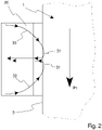
- Fig. 2 is a schematic illustration from above of the applicator head 20 of the continuous vacuum coating apparatus 21 during operation, i.e. during application of the water-based coating material to the side edge surface 3 of the tile element 1.
- the continuous vacuum coating apparatus 21 comprises means 22 for directing two flows 30 of the water-based coating material into the applicator head 20, towards the side edge surface 3 of the tile element 1.
- the continuous vacuum coating apparatus 21 further comprises means 23 for creating a vacuum or a negative pressure causing each flow 30 of water-based coating material to deflect and to be sucked back into the continuous vacuum coating apparatus 21.
- the side edge surface 3 of the tile element 1 is so positioned relative the applicator head 20 of the continuous vacuum coating apparatus 21 such that it engages a crest 31 formed by each flow 30 of coating material. Some of the water-based coating material will be applied to the side edge surface 3 while the excess coating material will be sucked back into the continuous vacuum coating apparatus 21 and be recirculated.
- the applicator head may have different configurations.
- the applicator head may be configured to apply the water-based coating material to a side edge surface comprising grooves and/or tongues.
- the tile element 1 After application of the water-based coating material to the side edge surface 3, the tile element 1 is transported to a drying section 40.
- the drying section 40 may be arranged for drying the water-based coating applied to the side edge surface 3 by means of IR-radiation.
- the drying section shown in Figs. 1a , b thus comprises IR-radiation means 41.
- the drying section may comprise micro wave radiation means or hot air means or a combination of IR-radiation means and/or micro wave radiation means and/or hot air means.
- the drying section may, as shown in Figs. 1a , b , have a longitudinal extension, wherein the IR-radiation means 41 and also steam generating means 42 are arranged at a first part S1 of the drying section 40 and wherein only the IR-radiation means 42 is arranged at a second part S2 of the drying section 40, the second part S2 being arranged downstream of the first part S1.
- the drying of the applied water-based coating material is controlled such that a coating layer formed by the applied coating material dries from inside and out.
- the tile element 1 may be kept in the drying section 40 for a period in the range of 8-45 s.
- the time period range for drying may be 20-45 s
- the time period range for drying may be 8-20 s.
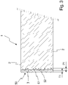
- Fig. 3 discloses a cross-sectional of a part of a tile element 1 after drying of the water-based coating material applied to the side edge surface 3 of the tile element 1.
- the applied water-based coating material forms a coating layer 50 comprising an outer coating layer 51 and an inner coating layer 52.
- the outer coating layer 51 corresponds to the part of the coating layer 50 that extends beyond the side edge surface 3 itself (indicated by a dotted line) of the tile element 1, and may have thickness T1 of at least 100 ⁇ m and may be in the range of 100-1500 ⁇ m.
- the inner coating 52 layer corresponds to the part of the coating layer 50 that due to the application method of the water-based coating material and the porosity of the compressed fibre material making up the tile element 1 penetrates the side edge surface 3 and extends into the tile element 1.
- the inner coating layer 52 may have a penetration depth P1 of at least 100 ⁇ m and may be in the range of 100-4000 ⁇ m.
- the water-based coating material may be applied with wet surface density in the range of 300-1600 g/m 2 .
- the thickness T1 of the outer coating layer 51 may have a non-uniform configuration.
- the penetration depth P1 of the inner coating layer 52 will due to the application method and porosity of the porous fibre material be non-uniform, as clearly illustrated in Fig. 3 .
- the average penetration depth may be in the range of 0,2-1,5 mm.
- the water-based coating material may be applied to all side edge surfaces 3 of the tile element 1.
- a water-based coating material which after application and drying forms a coating layer 50 with sufficient mechanical strength, it may hereby be possible to achieve a reinforcing frame structure enclosing the tile element 1, also referred to as edge-banding, improving the structural integrity of the tile element 1.
- the edge-banding effect may enable making the tile element of a porous fiber material with high porosity, such as glass wool of a relative low density, without having problems normally associated with low density, such as sagging.
- the inner coating layer 52 of the coating layer 50 may reinforce the side edge surface 3 in which the grooves and the like is to be formed.
- the mechanical strength of the coating layer 50 is dependent of the coating material used for forming the coating layer, the porosity of the fibre material of the tile element 1 and the amount of applied coating material, i.e. the surface density of the coating material. It is believed that it is the structure of the continuous vacuum coating apparatus applied coating layer 50 comprising an outer and an inner coating layer which enables the coating layer 50 to exhibit a relative high bending stiffness even for relatively moderate surface densities. Thus, the coating layer 50 applied to the side edge surface 3 of the inventive tile element 1 exhibits an improved mechanical strength.
- the characteristics of the coating material, the porosity of the fibre material and the surface density may be so selected that the coating layer 50 has a bending stiffness El cl of at least 60x10E5 Nmm 2 when applied to a planar side edge of a tile element having a thickness of 40 mm.
- the bending stiffness El cl of the coating layer may be measured in a three-point flexural bending test, which will be described below with reference to Figs. 4a and 4b .
- Two test sections 60 are cut from opposite sides of a tile element having a continuous vacuum coating apparatus applied coating layer 50 on its planar side edges.
- the two sections 60 are placed together with the side edges having the continuous vacuum coating apparatus applied coating layers 50 facing each other.
- instability phenomenon such as twisting and buckling is avoided or at least limited during the test.
- the surface that is supposed to face the room of the tile element is defined as the underside 62 of the test sections 60.
- the two sections 60 form a test specimen having a cross section of 2 x W x T (where W is the width of the test specimen and T is the thickness of the test specimen).
- the test specimen is placed on two supports 61 as a simply supported beam with the underside 62 facing downwards.
- the supports 61 has a span S.
- a load spreading membrane 63 may be placed on top of the test specimen at the mid of the span S and used in order to distribute load so that local "compression deformation" of the upper part of the test specimen is avoided.
- a load P is applied at the mid of the span S.
- the downward deflection y of the test specimen is measured at the center of the span S.
- the load P is increased until a deflection of a least 10% of the thickness T of the test specimen is achieved.
- El cl El sp ⁇ El ref / 2 , where El ref is the stiffness of a test specimen without any coating layer on the side edges.
- the planar side edges of tile elements having a thickness of 40 mm were provided with continuous vacuum coating apparatus applied coating layers.
- the coating material was applied with a wet surface density of about 1050 g/m 2 and for a tile element having a compressed fibre material density of 54 kg/m 3 , the coating material was applied with a wet surface density of about 620 g/m 2 .
- Test sections were cut from the tile elements, each test section having a width W of 50 mm, a thickness T of 40 mm and a length L of 550 mm. Test specimens formed from the test sections were placed supports 61 having a span S of 500 mm.
- the resulting bending stiffness El cl of the coating layer applied to the tile element having a compressed fibre material density of 27 kg/m 3 was 60 ⁇ 10E5 Nmm 2 .
- the bending stiffness El cl of the coating layer applied to the tile element having a compressed fibre material density of 54 kg/m 3 was about 70 ⁇ 10E5 Nmm 2 .
- the coating layer has a bending stiffness El cl of at least 60 ⁇ 10E5 Nmm 2 when applied to a planar side edge of a tile element having a thickness T of 40 mm (corresponding to the length of the coating layer as measured in a normal direction to the major surfaces of the tile element). If the thickness of the tile element is different, the bending stiffness El cl of coating layer may be calculated as El cl ⁇ T / 40 3 ⁇ 60 ⁇ 10 E 5 where T is thickness (in mm) of the tile element.
- the water-based coating material used in this invention may comprise at least one binder resin, fillers/pigments, solvent/diluent, and additives.
- Water is used as the main solvent/diluent.
- binder resins polymers may be used, such as those selected from acrylics, polyesters, polyurethanes, alkyds and mixtures or hybrids thereof.
- the binder resin is preferably used in the form a water-borne resin dispersion.
- Fillers for example, calcium carbonate, talc, dolomite, or clay may be used as fillers in the coating material.
- TiO 2 and/or ZnO are suitable inorganic pigments, but also carbon black and organic pigments can be used, depending on the desired color of the coating composition.
- Various additives can be used to provide for optimal physical characteristics of the coating material. These may include viscosity modifiers (such as urethane, acrylic, and cellulosic thickeners), defoamers (such as defoamers based on silicon oil or mineral oil), matting agents (such as silica, as well as micronized waxes of e.g. polyethylene, polypropylene, polyethylene terephthalate, and polytetrafluoroethylene), dispersing agents (such as charged polymers, block copolymers, and surfactants), surface wetting agents (such as siloxanes, gemini surfactants, and fluorosurfactants), and in-can biocides.
- viscosity modifiers such as urethane, acrylic, and cellulosic thickeners
- defoamers such as defoamers based on silicon oil or mineral oil
- matting agents such as silica, as well as micronized waxes of e.g. polyethylene, poly
- the coating material may be manufactured in a conventional way known by people skilled in the art of paint manufacturing - for example, by mixing all the ingredients using mixing equipment.
- the coating material have a viscosity in the range 50-200 Krebs unit (KU), more preferably in the range 80-160 KU and most preferably in the range of 105-115 KU.
- the viscosity can be measured using a viscometer of Stormer-type according to ASTM D562.
- PVC pigment volume concentration
- VOC volatile organic compounds
- the water-based coating material may comprise at least one of the following components: a coloring component such as a pigment, a shine regulating component, a UV-resistance promoting component, a mould growth inhibiting component, a fire resistance promoting component.
Landscapes
- Application Of Or Painting With Fluid Materials (AREA)
- Finishing Walls (AREA)
Claims (6)
- Verfahren zum Beschichten eines Fliesenelements (1), umfassend Vorsehen eines Fliesenelements (1), das aus einem komprimierten Fasermaterial mit einer Porosität in dem Bereich von 0,92-0,99 hergestellt ist, wobei das Fliesenelement (1) zwei gegenüberliegende Hauptflächen (2) aufweist, undAuftragen eines Beschichtungsmaterials auf Wasserbasis auf eine Seitenrandfläche (3) des Fliesenelements (1), die sich zwischen den zwei Hauptflächen (2) erstreckt, dadurch gekennzeichnet, dass der Schritt zum Auftragen des Beschichtungsmaterials auf Wasserbasis mittels eines Applikatorkopfes (20) einer kontinuierlichen Vakuumbeschichtungsvorrichtung (21) durchgeführt wird, wobei der Applikatorkopf (20) eingerichtet ist, um das Beschichtungsmaterial auf Wasserbasis auf die Seitenrandfläche (3) des Fliesenelements (1) aufzutragen und um einen Überschuss des Beschichtungsmaterials auf Wasserbasis durch ein Vakuum zu entfernen,wobei das Beschichtungsmaterial auf Wasserbasis bei einer Zuführrate des Fliesenelements (1) relativ zu dem Applikatorkopf (20) der kontinuierlichen Vakuumbeschichtungsvorrichtung (21) in dem Bereich von 25-150 m/min aufgetragen wird,wobei das Beschichtungsmaterial auf Wasserbasis auf die Seitenrandfläche (3) derart aufgetragen wird, dass eine Beschichtungsschicht (50) gebildet wird, die eine äußere Beschichtungsschicht (51), welche sich über die Seitenrandfläche (3) hinaus erstreckt, und eine innere Beschichtungsschicht (52), welche in die Seitenrandfläche (3) eindringt und sich in das Fliesenelement (1) erstreckt, umfasst, undwobei die innere Beschichtungsschicht (52) eine Eindringtiefe P1 von mindestens 100 µm und vorzugsweise in dem Bereich von 100-4000 µm aufweist.
- Verfahren nach Anspruch 1, wobei das Beschichtungsmaterial auf Wasserbasis auf alle Seitenrandflächen (3) aufgetragen wird, die sich zwischen den zwei Hauptflächen (2) des Fliesenelements (1) erstrecken.
- Verfahren nach Anspruch 1 oder 2, ferner umfassend Trocknen des aufgetragenen Beschichtungsmaterials auf Wasserbasis mittels IR-Strahlung und/oder Mikrowellen-Strahlung.
- Verfahren nach einem der Ansprüche 1-3, wobei die äußere Beschichtungsschicht (51) eine Dicke T1 von mindestens 100 µm und vorzugsweise in dem Bereich von 100-1500 µm aufweist.
- Verfahren nach einem der vorhergehenden Ansprüche, wobei das Beschichtungsmaterial auf Wasserbasis auf die Seitenrandfläche (3) mit einer nassen Oberflächendichte in dem Bereich von 300-1600 g/m2 aufgetragen wird.
- Verfahren nach einem der vorhergehenden Ansprüche, wobei das Beschichtungsmaterial auf Wasserbasis einen Trockengehalt von mindestens 60 Gew.-% und vorzugsweise in dem Bereich von 60-80 Gew.-% aufweist.
Priority Applications (7)
| Application Number | Priority Date | Filing Date | Title |
|---|---|---|---|
| EP18182178.6A EP3590610B1 (de) | 2018-07-06 | 2018-07-06 | Verfahren zum beschichten eines fliesenelements |
| PL18182178.6T PL3590610T3 (pl) | 2018-07-06 | 2018-07-06 | Sposób powlekania elementu płytki |
| DK18182178.6T DK3590610T3 (en) | 2018-07-06 | 2018-07-06 | Fremgangsmåde til at coate et fliseelement. |
| BR112020025714-1A BR112020025714A2 (pt) | 2018-07-06 | 2019-07-01 | Método para revestir um elemento de telha |
| PCT/EP2019/067568 WO2020007782A1 (en) | 2018-07-06 | 2019-07-01 | Method for coating a tile element |
| CA3105640A CA3105640A1 (en) | 2018-07-06 | 2019-07-01 | Method for coating a tile element |
| US17/256,448 US11679410B2 (en) | 2018-07-06 | 2019-07-01 | Method for coating a tile element |
Applications Claiming Priority (1)
| Application Number | Priority Date | Filing Date | Title |
|---|---|---|---|
| EP18182178.6A EP3590610B1 (de) | 2018-07-06 | 2018-07-06 | Verfahren zum beschichten eines fliesenelements |
Publications (2)
| Publication Number | Publication Date |
|---|---|
| EP3590610A1 EP3590610A1 (de) | 2020-01-08 |
| EP3590610B1 true EP3590610B1 (de) | 2022-04-20 |
Family
ID=62951849
Family Applications (1)
| Application Number | Title | Priority Date | Filing Date |
|---|---|---|---|
| EP18182178.6A Active EP3590610B1 (de) | 2018-07-06 | 2018-07-06 | Verfahren zum beschichten eines fliesenelements |
Country Status (7)
| Country | Link |
|---|---|
| US (1) | US11679410B2 (de) |
| EP (1) | EP3590610B1 (de) |
| BR (1) | BR112020025714A2 (de) |
| CA (1) | CA3105640A1 (de) |
| DK (1) | DK3590610T3 (de) |
| PL (1) | PL3590610T3 (de) |
| WO (1) | WO2020007782A1 (de) |
Families Citing this family (3)
| Publication number | Priority date | Publication date | Assignee | Title |
|---|---|---|---|---|
| CN111318418B (zh) * | 2020-02-25 | 2021-10-22 | 林永养 | 方形中空玻璃涂胶装置 |
| PT3885052T (pt) | 2020-03-24 | 2023-01-30 | Akzenta Paneele Profile Gmbh | Revestimento do bordo de um painel com um meio de revestimento |
| WO2022096746A1 (en) | 2020-11-09 | 2022-05-12 | Rockwool International A/S | Acoustic panel edge |
Citations (7)
| Publication number | Priority date | Publication date | Assignee | Title |
|---|---|---|---|---|
| GB2264658A (en) | 1992-03-06 | 1993-09-08 | Josef Schiele | An edge coating head |
| EP1228812A1 (de) | 2001-01-31 | 2002-08-07 | Rockwool International A/S | Verfahren und Vorrichtung zum Beschichten von Rändern von Mineralfaserplatten |
| DE102004038447A1 (de) | 2004-08-07 | 2006-02-23 | Deutsche Rockwool Mineralwoll Gmbh & Co. Ohg | Dämmelement aus Mineralfasern und Wärmedämmverbundsystem für Gebäudeflächen |
| WO2009135811A1 (en) | 2008-05-06 | 2009-11-12 | Rockwool International A/S | Suspended ceiling with 3 layer ceiling plates |
| US20150069150A1 (en) | 2013-09-10 | 2015-03-12 | Armstrong World Industries, Inc. | System for applying a coating to a workpiece |
| WO2017055561A1 (de) | 2015-10-02 | 2017-04-06 | Homag Gmbh | Verfahren sowie vorrichtung zur schmalflächenbeschichtung |
| US20180016785A1 (en) | 2016-07-12 | 2018-01-18 | Armstrong World Industries, Inc. | High solids color face and edge coatings for building panels |
Family Cites Families (6)
| Publication number | Priority date | Publication date | Assignee | Title |
|---|---|---|---|---|
| US4074655A (en) * | 1976-10-18 | 1978-02-21 | Armstrong Cork Company | Edge coating applicator nozzle |
| DD137788A3 (de) * | 1978-05-17 | 1979-09-26 | Eckerhard Pruefer | Verfahren und vorrichtung zum retuschieren von kanten |
| DE4021174C2 (de) | 1990-07-03 | 1994-08-11 | Josef Schiele | Anlage zum Durchlauf-Vakuum-Flüssigbeschichten |
| DE69122355T2 (de) | 1990-11-20 | 1997-04-17 | Asahi Chemical Ind | Reinigungszusammensetzung für eine Formmaschine sowie Reinigungsmethode |
| DE19622921C3 (de) * | 1996-06-07 | 2003-09-18 | Basf Coatings Ag | Verfahren zur Herstellung eines Schichtstoffes und dessen Verwendung |
| EP1743076B2 (de) | 2004-04-02 | 2023-04-19 | Rockwool A/S | Akustische Elemente und deren Herstellung |
-
2018
- 2018-07-06 DK DK18182178.6T patent/DK3590610T3/da active
- 2018-07-06 PL PL18182178.6T patent/PL3590610T3/pl unknown
- 2018-07-06 EP EP18182178.6A patent/EP3590610B1/de active Active
-
2019
- 2019-07-01 WO PCT/EP2019/067568 patent/WO2020007782A1/en active Application Filing
- 2019-07-01 US US17/256,448 patent/US11679410B2/en active Active
- 2019-07-01 BR BR112020025714-1A patent/BR112020025714A2/pt unknown
- 2019-07-01 CA CA3105640A patent/CA3105640A1/en active Pending
Patent Citations (7)
| Publication number | Priority date | Publication date | Assignee | Title |
|---|---|---|---|---|
| GB2264658A (en) | 1992-03-06 | 1993-09-08 | Josef Schiele | An edge coating head |
| EP1228812A1 (de) | 2001-01-31 | 2002-08-07 | Rockwool International A/S | Verfahren und Vorrichtung zum Beschichten von Rändern von Mineralfaserplatten |
| DE102004038447A1 (de) | 2004-08-07 | 2006-02-23 | Deutsche Rockwool Mineralwoll Gmbh & Co. Ohg | Dämmelement aus Mineralfasern und Wärmedämmverbundsystem für Gebäudeflächen |
| WO2009135811A1 (en) | 2008-05-06 | 2009-11-12 | Rockwool International A/S | Suspended ceiling with 3 layer ceiling plates |
| US20150069150A1 (en) | 2013-09-10 | 2015-03-12 | Armstrong World Industries, Inc. | System for applying a coating to a workpiece |
| WO2017055561A1 (de) | 2015-10-02 | 2017-04-06 | Homag Gmbh | Verfahren sowie vorrichtung zur schmalflächenbeschichtung |
| US20180016785A1 (en) | 2016-07-12 | 2018-01-18 | Armstrong World Industries, Inc. | High solids color face and edge coatings for building panels |
Also Published As
| Publication number | Publication date |
|---|---|
| CA3105640A1 (en) | 2020-01-09 |
| US20210268539A1 (en) | 2021-09-02 |
| EP3590610A1 (de) | 2020-01-08 |
| US11679410B2 (en) | 2023-06-20 |
| DK3590610T3 (en) | 2022-06-07 |
| BR112020025714A2 (pt) | 2021-03-16 |
| WO2020007782A1 (en) | 2020-01-09 |
| PL3590610T3 (pl) | 2022-09-26 |
Similar Documents
| Publication | Publication Date | Title |
|---|---|---|
| US11679410B2 (en) | Method for coating a tile element | |
| US11280090B2 (en) | Gypsum board suitable for wet or humid areas | |
| US10899107B2 (en) | Building membrane with porous pressure sensitive adhesive | |
| DE60213334T2 (de) | Verfahren zur Herstellung einer schaumbeschichteten Matte, und beschichtete Mattenprodukte | |
| US7807592B2 (en) | Interior wallboard and method of making same | |
| US7989370B2 (en) | Interior wallboard and method of making same | |
| FI81391B (fi) | Flor- eller vaevbaserat belaeggningsskiktmaterial. | |
| KR20170088333A (ko) | 습윤 지역 또는 습한 지역에 적합한 매트 및 석고 보드 | |
| DE10300584B4 (de) | Flexible Schichtplatte mit Wabenstruktur | |
| CN103216047A (zh) | 耐火性纤维素-沥青屋顶覆盖片材及其制造方法 | |
| US20200325681A1 (en) | Pelletization of recycled ceilnig material | |
| US20190136524A1 (en) | Water stain and sag resistant acoustic building panel | |
| JPH0333838B2 (de) | ||
| CA2887481C (en) | Building membrane with porous pressure sensitive adhesive | |
| DE202020005905U1 (de) | Zementfolien und -beschichtungen für den Hochbau | |
| DE69927038T2 (de) | Geschäumte beschichtung und damit hergestellte isolationsplatten | |
| EP1900511A1 (de) | Verfahren zum Herstellen einer Schicht mit einer Deckschicht und einem Träger und Schicht mit Deckschicht und Träger | |
| JPH0253557B2 (de) | ||
| US20230076832A1 (en) | Acoustical building panel and surface covering systems utilizing the same | |
| RU2776074C2 (ru) | Гипсовые панели, подходящие для влажных или сырых зон | |
| JP2543390C (de) |
Legal Events
| Date | Code | Title | Description |
|---|---|---|---|
| PUAI | Public reference made under article 153(3) epc to a published international application that has entered the european phase |
Free format text: ORIGINAL CODE: 0009012 |
|
| STAA | Information on the status of an ep patent application or granted ep patent |
Free format text: STATUS: THE APPLICATION HAS BEEN PUBLISHED |
|
| AK | Designated contracting states |
Kind code of ref document: A1 Designated state(s): AL AT BE BG CH CY CZ DE DK EE ES FI FR GB GR HR HU IE IS IT LI LT LU LV MC MK MT NL NO PL PT RO RS SE SI SK SM TR |
|
| AX | Request for extension of the european patent |
Extension state: BA ME |
|
| STAA | Information on the status of an ep patent application or granted ep patent |
Free format text: STATUS: REQUEST FOR EXAMINATION WAS MADE |
|
| 17P | Request for examination filed |
Effective date: 20200703 |
|
| RBV | Designated contracting states (corrected) |
Designated state(s): AL AT BE BG CH CY CZ DE DK EE ES FI FR GB GR HR HU IE IS IT LI LT LU LV MC MK MT NL NO PL PT RO RS SE SI SK SM TR |
|
| GRAP | Despatch of communication of intention to grant a patent |
Free format text: ORIGINAL CODE: EPIDOSNIGR1 |
|
| STAA | Information on the status of an ep patent application or granted ep patent |
Free format text: STATUS: GRANT OF PATENT IS INTENDED |
|
| RIC1 | Information provided on ipc code assigned before grant |
Ipc: B05D 3/04 20060101ALN20211029BHEP Ipc: B05C 5/02 20060101ALI20211029BHEP Ipc: B05D 3/02 20060101ALI20211029BHEP Ipc: B05D 1/26 20060101AFI20211029BHEP |
|
| INTG | Intention to grant announced |
Effective date: 20211117 |
|
| RIC1 | Information provided on ipc code assigned before grant |
Ipc: B05C 5/02 20060101ALN20211108BHEP Ipc: B05D 3/04 20060101ALN20211108BHEP Ipc: B05D 3/02 20060101ALI20211108BHEP Ipc: B05D 1/26 20060101AFI20211108BHEP |
|
| GRAS | Grant fee paid |
Free format text: ORIGINAL CODE: EPIDOSNIGR3 |
|
| GRAA | (expected) grant |
Free format text: ORIGINAL CODE: 0009210 |
|
| STAA | Information on the status of an ep patent application or granted ep patent |
Free format text: STATUS: THE PATENT HAS BEEN GRANTED |
|
| AK | Designated contracting states |
Kind code of ref document: B1 Designated state(s): AL AT BE BG CH CY CZ DE DK EE ES FI FR GB GR HR HU IE IS IT LI LT LU LV MC MK MT NL NO PL PT RO RS SE SI SK SM TR |
|
| REG | Reference to a national code |
Ref country code: GB Ref legal event code: FG4D |
|
| REG | Reference to a national code |
Ref country code: CH Ref legal event code: EP |
|
| REG | Reference to a national code |
Ref country code: DE Ref legal event code: R096 Ref document number: 602018034028 Country of ref document: DE |
|
| REG | Reference to a national code |
Ref country code: IE Ref legal event code: FG4D |
|
| REG | Reference to a national code |
Ref country code: AT Ref legal event code: REF Ref document number: 1484757 Country of ref document: AT Kind code of ref document: T Effective date: 20220515 |
|
| REG | Reference to a national code |
Ref country code: DK Ref legal event code: T3 Effective date: 20220602 |
|
| REG | Reference to a national code |
Ref country code: NL Ref legal event code: FP |
|
| REG | Reference to a national code |
Ref country code: FI Ref legal event code: FGE |
|
| REG | Reference to a national code |
Ref country code: SE Ref legal event code: TRGR |
|
| REG | Reference to a national code |
Ref country code: LT Ref legal event code: MG9D |
|
| REG | Reference to a national code |
Ref country code: NO Ref legal event code: T2 Effective date: 20220420 |
|
| REG | Reference to a national code |
Ref country code: AT Ref legal event code: MK05 Ref document number: 1484757 Country of ref document: AT Kind code of ref document: T Effective date: 20220420 |
|
| PG25 | Lapsed in a contracting state [announced via postgrant information from national office to epo] |
Ref country code: PT Free format text: LAPSE BECAUSE OF FAILURE TO SUBMIT A TRANSLATION OF THE DESCRIPTION OR TO PAY THE FEE WITHIN THE PRESCRIBED TIME-LIMIT Effective date: 20220822 Ref country code: LT Free format text: LAPSE BECAUSE OF FAILURE TO SUBMIT A TRANSLATION OF THE DESCRIPTION OR TO PAY THE FEE WITHIN THE PRESCRIBED TIME-LIMIT Effective date: 20220420 Ref country code: HR Free format text: LAPSE BECAUSE OF FAILURE TO SUBMIT A TRANSLATION OF THE DESCRIPTION OR TO PAY THE FEE WITHIN THE PRESCRIBED TIME-LIMIT Effective date: 20220420 Ref country code: GR Free format text: LAPSE BECAUSE OF FAILURE TO SUBMIT A TRANSLATION OF THE DESCRIPTION OR TO PAY THE FEE WITHIN THE PRESCRIBED TIME-LIMIT Effective date: 20220721 Ref country code: ES Free format text: LAPSE BECAUSE OF FAILURE TO SUBMIT A TRANSLATION OF THE DESCRIPTION OR TO PAY THE FEE WITHIN THE PRESCRIBED TIME-LIMIT Effective date: 20220420 Ref country code: BG Free format text: LAPSE BECAUSE OF FAILURE TO SUBMIT A TRANSLATION OF THE DESCRIPTION OR TO PAY THE FEE WITHIN THE PRESCRIBED TIME-LIMIT Effective date: 20220720 Ref country code: AT Free format text: LAPSE BECAUSE OF FAILURE TO SUBMIT A TRANSLATION OF THE DESCRIPTION OR TO PAY THE FEE WITHIN THE PRESCRIBED TIME-LIMIT Effective date: 20220420 |
|
| PG25 | Lapsed in a contracting state [announced via postgrant information from national office to epo] |
Ref country code: RS Free format text: LAPSE BECAUSE OF FAILURE TO SUBMIT A TRANSLATION OF THE DESCRIPTION OR TO PAY THE FEE WITHIN THE PRESCRIBED TIME-LIMIT Effective date: 20220420 Ref country code: LV Free format text: LAPSE BECAUSE OF FAILURE TO SUBMIT A TRANSLATION OF THE DESCRIPTION OR TO PAY THE FEE WITHIN THE PRESCRIBED TIME-LIMIT Effective date: 20220420 Ref country code: IS Free format text: LAPSE BECAUSE OF FAILURE TO SUBMIT A TRANSLATION OF THE DESCRIPTION OR TO PAY THE FEE WITHIN THE PRESCRIBED TIME-LIMIT Effective date: 20220820 |
|
| REG | Reference to a national code |
Ref country code: DE Ref legal event code: R026 Ref document number: 602018034028 Country of ref document: DE |
|
| PLBI | Opposition filed |
Free format text: ORIGINAL CODE: 0009260 |
|
| PG25 | Lapsed in a contracting state [announced via postgrant information from national office to epo] |
Ref country code: SM Free format text: LAPSE BECAUSE OF FAILURE TO SUBMIT A TRANSLATION OF THE DESCRIPTION OR TO PAY THE FEE WITHIN THE PRESCRIBED TIME-LIMIT Effective date: 20220420 Ref country code: SK Free format text: LAPSE BECAUSE OF FAILURE TO SUBMIT A TRANSLATION OF THE DESCRIPTION OR TO PAY THE FEE WITHIN THE PRESCRIBED TIME-LIMIT Effective date: 20220420 Ref country code: RO Free format text: LAPSE BECAUSE OF FAILURE TO SUBMIT A TRANSLATION OF THE DESCRIPTION OR TO PAY THE FEE WITHIN THE PRESCRIBED TIME-LIMIT Effective date: 20220420 Ref country code: EE Free format text: LAPSE BECAUSE OF FAILURE TO SUBMIT A TRANSLATION OF THE DESCRIPTION OR TO PAY THE FEE WITHIN THE PRESCRIBED TIME-LIMIT Effective date: 20220420 Ref country code: CZ Free format text: LAPSE BECAUSE OF FAILURE TO SUBMIT A TRANSLATION OF THE DESCRIPTION OR TO PAY THE FEE WITHIN THE PRESCRIBED TIME-LIMIT Effective date: 20220420 |
|
| PLAX | Notice of opposition and request to file observation + time limit sent |
Free format text: ORIGINAL CODE: EPIDOSNOBS2 |
|
| 26 | Opposition filed |
Opponent name: ROCKWOOL A/S Effective date: 20230112 |
|
| PG25 | Lapsed in a contracting state [announced via postgrant information from national office to epo] |
Ref country code: MC Free format text: LAPSE BECAUSE OF FAILURE TO SUBMIT A TRANSLATION OF THE DESCRIPTION OR TO PAY THE FEE WITHIN THE PRESCRIBED TIME-LIMIT Effective date: 20220420 |
|
| REG | Reference to a national code |
Ref country code: CH Ref legal event code: PL |
|
| REG | Reference to a national code |
Ref country code: BE Ref legal event code: MM Effective date: 20220731 |
|
| PG25 | Lapsed in a contracting state [announced via postgrant information from national office to epo] |
Ref country code: AL Free format text: LAPSE BECAUSE OF FAILURE TO SUBMIT A TRANSLATION OF THE DESCRIPTION OR TO PAY THE FEE WITHIN THE PRESCRIBED TIME-LIMIT Effective date: 20220420 |
|
| PG25 | Lapsed in a contracting state [announced via postgrant information from national office to epo] |
Ref country code: LU Free format text: LAPSE BECAUSE OF NON-PAYMENT OF DUE FEES Effective date: 20220706 Ref country code: LI Free format text: LAPSE BECAUSE OF NON-PAYMENT OF DUE FEES Effective date: 20220731 Ref country code: CH Free format text: LAPSE BECAUSE OF NON-PAYMENT OF DUE FEES Effective date: 20220731 |
|
| PG25 | Lapsed in a contracting state [announced via postgrant information from national office to epo] |
Ref country code: SI Free format text: LAPSE BECAUSE OF FAILURE TO SUBMIT A TRANSLATION OF THE DESCRIPTION OR TO PAY THE FEE WITHIN THE PRESCRIBED TIME-LIMIT Effective date: 20220420 Ref country code: BE Free format text: LAPSE BECAUSE OF NON-PAYMENT OF DUE FEES Effective date: 20220731 |
|
| PLBB | Reply of patent proprietor to notice(s) of opposition received |
Free format text: ORIGINAL CODE: EPIDOSNOBS3 |
|
| PG25 | Lapsed in a contracting state [announced via postgrant information from national office to epo] |
Ref country code: IE Free format text: LAPSE BECAUSE OF NON-PAYMENT OF DUE FEES Effective date: 20220706 |
|
| PGFP | Annual fee paid to national office [announced via postgrant information from national office to epo] |
Ref country code: NO Payment date: 20230620 Year of fee payment: 6 Ref country code: NL Payment date: 20230621 Year of fee payment: 6 Ref country code: FR Payment date: 20230616 Year of fee payment: 6 Ref country code: DK Payment date: 20230620 Year of fee payment: 6 |
|
| PGFP | Annual fee paid to national office [announced via postgrant information from national office to epo] |
Ref country code: SE Payment date: 20230616 Year of fee payment: 6 Ref country code: FI Payment date: 20230616 Year of fee payment: 6 |
|
| PGFP | Annual fee paid to national office [announced via postgrant information from national office to epo] |
Ref country code: GB Payment date: 20230615 Year of fee payment: 6 |
|
| PGFP | Annual fee paid to national office [announced via postgrant information from national office to epo] |
Ref country code: PL Payment date: 20230703 Year of fee payment: 6 Ref country code: DE Payment date: 20230619 Year of fee payment: 6 |
|
| PG25 | Lapsed in a contracting state [announced via postgrant information from national office to epo] |
Ref country code: IT Free format text: LAPSE BECAUSE OF FAILURE TO SUBMIT A TRANSLATION OF THE DESCRIPTION OR TO PAY THE FEE WITHIN THE PRESCRIBED TIME-LIMIT Effective date: 20220420 |
|
| PG25 | Lapsed in a contracting state [announced via postgrant information from national office to epo] |
Ref country code: HU Free format text: LAPSE BECAUSE OF FAILURE TO SUBMIT A TRANSLATION OF THE DESCRIPTION OR TO PAY THE FEE WITHIN THE PRESCRIBED TIME-LIMIT; INVALID AB INITIO Effective date: 20180706 |
|
| PG25 | Lapsed in a contracting state [announced via postgrant information from national office to epo] |
Ref country code: MK Free format text: LAPSE BECAUSE OF FAILURE TO SUBMIT A TRANSLATION OF THE DESCRIPTION OR TO PAY THE FEE WITHIN THE PRESCRIBED TIME-LIMIT Effective date: 20220420 Ref country code: CY Free format text: LAPSE BECAUSE OF FAILURE TO SUBMIT A TRANSLATION OF THE DESCRIPTION OR TO PAY THE FEE WITHIN THE PRESCRIBED TIME-LIMIT Effective date: 20220420 |