EP3590607A1 - Liquid application unit and liquid application device - Google Patents
Liquid application unit and liquid application device Download PDFInfo
- Publication number
- EP3590607A1 EP3590607A1 EP18756923.1A EP18756923A EP3590607A1 EP 3590607 A1 EP3590607 A1 EP 3590607A1 EP 18756923 A EP18756923 A EP 18756923A EP 3590607 A1 EP3590607 A1 EP 3590607A1
- Authority
- EP
- European Patent Office
- Prior art keywords
- application
- application needle
- liquid
- driving unit
- unit
- Prior art date
- Legal status (The legal status is an assumption and is not a legal conclusion. Google has not performed a legal analysis and makes no representation as to the accuracy of the status listed.)
- Granted
Links
Images






Classifications
-
- B—PERFORMING OPERATIONS; TRANSPORTING
- B05—SPRAYING OR ATOMISING IN GENERAL; APPLYING FLUENT MATERIALS TO SURFACES, IN GENERAL
- B05C—APPARATUS FOR APPLYING FLUENT MATERIALS TO SURFACES, IN GENERAL
- B05C1/00—Apparatus in which liquid or other fluent material is applied to the surface of the work by contact with a member carrying the liquid or other fluent material, e.g. a porous member loaded with a liquid to be applied as a coating
- B05C1/02—Apparatus in which liquid or other fluent material is applied to the surface of the work by contact with a member carrying the liquid or other fluent material, e.g. a porous member loaded with a liquid to be applied as a coating for applying liquid or other fluent material to separate articles
-
- B—PERFORMING OPERATIONS; TRANSPORTING
- B05—SPRAYING OR ATOMISING IN GENERAL; APPLYING FLUENT MATERIALS TO SURFACES, IN GENERAL
- B05C—APPARATUS FOR APPLYING FLUENT MATERIALS TO SURFACES, IN GENERAL
- B05C1/00—Apparatus in which liquid or other fluent material is applied to the surface of the work by contact with a member carrying the liquid or other fluent material, e.g. a porous member loaded with a liquid to be applied as a coating
- B05C1/02—Apparatus in which liquid or other fluent material is applied to the surface of the work by contact with a member carrying the liquid or other fluent material, e.g. a porous member loaded with a liquid to be applied as a coating for applying liquid or other fluent material to separate articles
- B05C1/027—Apparatus in which liquid or other fluent material is applied to the surface of the work by contact with a member carrying the liquid or other fluent material, e.g. a porous member loaded with a liquid to be applied as a coating for applying liquid or other fluent material to separate articles only at particular parts of the articles
-
- B—PERFORMING OPERATIONS; TRANSPORTING
- B01—PHYSICAL OR CHEMICAL PROCESSES OR APPARATUS IN GENERAL
- B01L—CHEMICAL OR PHYSICAL LABORATORY APPARATUS FOR GENERAL USE
- B01L3/00—Containers or dishes for laboratory use, e.g. laboratory glassware; Droppers
- B01L3/02—Burettes; Pipettes
- B01L3/0241—Drop counters; Drop formers
- B01L3/0262—Drop counters; Drop formers using touch-off at substrate or container
-
- B—PERFORMING OPERATIONS; TRANSPORTING
- B05—SPRAYING OR ATOMISING IN GENERAL; APPLYING FLUENT MATERIALS TO SURFACES, IN GENERAL
- B05C—APPARATUS FOR APPLYING FLUENT MATERIALS TO SURFACES, IN GENERAL
- B05C11/00—Component parts, details or accessories not specifically provided for in groups B05C1/00 - B05C9/00
-
- B—PERFORMING OPERATIONS; TRANSPORTING
- B05—SPRAYING OR ATOMISING IN GENERAL; APPLYING FLUENT MATERIALS TO SURFACES, IN GENERAL
- B05C—APPARATUS FOR APPLYING FLUENT MATERIALS TO SURFACES, IN GENERAL
- B05C11/00—Component parts, details or accessories not specifically provided for in groups B05C1/00 - B05C9/00
- B05C11/10—Storage, supply or control of liquid or other fluent material; Recovery of excess liquid or other fluent material
-
- B—PERFORMING OPERATIONS; TRANSPORTING
- B05—SPRAYING OR ATOMISING IN GENERAL; APPLYING FLUENT MATERIALS TO SURFACES, IN GENERAL
- B05C—APPARATUS FOR APPLYING FLUENT MATERIALS TO SURFACES, IN GENERAL
- B05C11/00—Component parts, details or accessories not specifically provided for in groups B05C1/00 - B05C9/00
- B05C11/10—Storage, supply or control of liquid or other fluent material; Recovery of excess liquid or other fluent material
- B05C11/1002—Means for controlling supply, i.e. flow or pressure, of liquid or other fluent material to the applying apparatus, e.g. valves
- B05C11/1034—Means for controlling supply, i.e. flow or pressure, of liquid or other fluent material to the applying apparatus, e.g. valves specially designed for conducting intermittent application of small quantities, e.g. drops, of coating material
-
- B—PERFORMING OPERATIONS; TRANSPORTING
- B05—SPRAYING OR ATOMISING IN GENERAL; APPLYING FLUENT MATERIALS TO SURFACES, IN GENERAL
- B05C—APPARATUS FOR APPLYING FLUENT MATERIALS TO SURFACES, IN GENERAL
- B05C5/00—Apparatus in which liquid or other fluent material is projected, poured or allowed to flow on to the surface of the work
-
- B—PERFORMING OPERATIONS; TRANSPORTING
- B05—SPRAYING OR ATOMISING IN GENERAL; APPLYING FLUENT MATERIALS TO SURFACES, IN GENERAL
- B05C—APPARATUS FOR APPLYING FLUENT MATERIALS TO SURFACES, IN GENERAL
- B05C5/00—Apparatus in which liquid or other fluent material is projected, poured or allowed to flow on to the surface of the work
- B05C5/02—Apparatus in which liquid or other fluent material is projected, poured or allowed to flow on to the surface of the work the liquid or other fluent material being discharged through an outlet orifice by pressure, e.g. from an outlet device in contact or almost in contact, with the work
- B05C5/0225—Apparatus in which liquid or other fluent material is projected, poured or allowed to flow on to the surface of the work the liquid or other fluent material being discharged through an outlet orifice by pressure, e.g. from an outlet device in contact or almost in contact, with the work characterised by flow controlling means, e.g. valves, located proximate the outlet
-
- B—PERFORMING OPERATIONS; TRANSPORTING
- B01—PHYSICAL OR CHEMICAL PROCESSES OR APPARATUS IN GENERAL
- B01J—CHEMICAL OR PHYSICAL PROCESSES, e.g. CATALYSIS OR COLLOID CHEMISTRY; THEIR RELEVANT APPARATUS
- B01J2219/00—Chemical, physical or physico-chemical processes in general; Their relevant apparatus
- B01J2219/00274—Sequential or parallel reactions; Apparatus and devices for combinatorial chemistry or for making arrays; Chemical library technology
- B01J2219/00277—Apparatus
- B01J2219/00351—Means for dispensing and evacuation of reagents
- B01J2219/00373—Hollow needles
-
- B—PERFORMING OPERATIONS; TRANSPORTING
- B01—PHYSICAL OR CHEMICAL PROCESSES OR APPARATUS IN GENERAL
- B01L—CHEMICAL OR PHYSICAL LABORATORY APPARATUS FOR GENERAL USE
- B01L2300/00—Additional constructional details
- B01L2300/08—Geometry, shape and general structure
- B01L2300/0809—Geometry, shape and general structure rectangular shaped
- B01L2300/0819—Microarrays; Biochips
-
- B—PERFORMING OPERATIONS; TRANSPORTING
- B01—PHYSICAL OR CHEMICAL PROCESSES OR APPARATUS IN GENERAL
- B01L—CHEMICAL OR PHYSICAL LABORATORY APPARATUS FOR GENERAL USE
- B01L3/00—Containers or dishes for laboratory use, e.g. laboratory glassware; Droppers
- B01L3/02—Burettes; Pipettes
- B01L3/0241—Drop counters; Drop formers
- B01L3/0244—Drop counters; Drop formers using pins
-
- B—PERFORMING OPERATIONS; TRANSPORTING
- B01—PHYSICAL OR CHEMICAL PROCESSES OR APPARATUS IN GENERAL
- B01L—CHEMICAL OR PHYSICAL LABORATORY APPARATUS FOR GENERAL USE
- B01L9/00—Supporting devices; Holding devices
- B01L9/52—Supports specially adapted for flat sample carriers, e.g. for plates, slides, chips
-
- B—PERFORMING OPERATIONS; TRANSPORTING
- B05—SPRAYING OR ATOMISING IN GENERAL; APPLYING FLUENT MATERIALS TO SURFACES, IN GENERAL
- B05C—APPARATUS FOR APPLYING FLUENT MATERIALS TO SURFACES, IN GENERAL
- B05C5/00—Apparatus in which liquid or other fluent material is projected, poured or allowed to flow on to the surface of the work
- B05C5/02—Apparatus in which liquid or other fluent material is projected, poured or allowed to flow on to the surface of the work the liquid or other fluent material being discharged through an outlet orifice by pressure, e.g. from an outlet device in contact or almost in contact, with the work
- B05C5/027—Coating heads with several outlets, e.g. aligned transversally to the moving direction of a web to be coated
-
- B—PERFORMING OPERATIONS; TRANSPORTING
- B05—SPRAYING OR ATOMISING IN GENERAL; APPLYING FLUENT MATERIALS TO SURFACES, IN GENERAL
- B05D—PROCESSES FOR APPLYING FLUENT MATERIALS TO SURFACES, IN GENERAL
- B05D7/00—Processes, other than flocking, specially adapted for applying liquids or other fluent materials to particular surfaces or for applying particular liquids or other fluent materials
- B05D7/24—Processes, other than flocking, specially adapted for applying liquids or other fluent materials to particular surfaces or for applying particular liquids or other fluent materials for applying particular liquids or other fluent materials
Definitions
- the present invention relates to a liquid application unit and a liquid application apparatus, and also relates to a liquid application unit and a liquid application apparatus each for applying a liquid material to a target using an application needle.
- biochips are used in inspections and the like for identifying a pathogen for the purpose of finding diseases in an early stage.
- a plurality of antibody materials and the like are applied in advance to one biochip, for example, such that a plurality of types of diseases can be examined in one inspection.
- the bonding state of an antigen and each antibody material on one biochip is examined to identify a foreign substance containing this antigen.
- the method of applying an antibody material to a biochip includes a dispenser scheme, an ink jet scheme, an application needle scheme, and the like.
- liquid application unit disclosed in Japanese Patent Laying-Open No. 2015-112577 is used.
- the liquid application unit allows an extremely fine application to be performed at high speed and with stability.
- each of the plurality of application needles and each of the plurality of liquid materials may need to be simultaneously resupplied or replaced.
- a plurality of application needles in their respective liquid application units need to be separately replaced, and also, a liquid material needs to be resupplied to each of a plurality of liquid material containers separately. Then, driving of each of the plurality of liquid application units needs to be stopped from the start to the end of the resupplying operation.
- a main object of the present invention is to provide a liquid application unit and a liquid application apparatus, for which at least either of a plurality of application needles and a plurality of liquid materials can be readily resupplied or replaced.
- a liquid application unit serves as a liquid application unit for applying a liquid material onto a surface of a target using an application needle.
- the liquid application unit includes: a plurality of application needle units each including the application needle and a liquid material container in which the liquid material is stored and from which the liquid material is supplied to the application needle; and a first driving unit configured to move the application needle relative to the target and the liquid material container in a first direction.
- the plurality of application needle units are integrally attachable to and detachable from the first driving unit.
- a liquid application apparatus includes: the liquid application unit; and a holding base configured to hold the target.
- a liquid application unit and a liquid application apparatus can be provided, for which at least either of a plurality of application needles and a plurality of liquid materials can be readily resupplied or replaced.
- a liquid application unit 100 includes a plurality of application needle units 10 and one first driving unit 20.
- each of the plurality of application needle units 10 includes: an application needle 1; and a liquid material container 2 in which a liquid material is stored and from which the liquid material is supplied to application needle 1.
- first driving unit 20 moves application needle 1 in the first direction relative to a substrate 140 (see Fig. 5 ) as a target to which the liquid material is applied and liquid material container 2.
- the first direction may be any direction, but may be the gravity direction, for example.
- First driving unit 20 includes a servo motor 3 as a driving source, for example, a cam member 5, a bearing 6, a connection member 7, and a movable unit 8.
- Cam member 5 is attached to a rotation member 4 of servo motor 3 and rotated about the rotation axis of rotation member 4 together with rotation member 4.
- the rotation axis of rotation member 4 is located to extend in the first direction.
- Cam member 5 has a surface that is located on the side of servo motor 3 and that is formed as an annular cam surface disposed to surround rotation member 4.
- the cam surface has: two surface portions, for example, that are orthogonal to the first direction and that are different in distance from servo motor 3 in the first direction; and two surface portions that cross the first direction and that connect the above-mentioned two surface portions.
- the cam surface is in contact with the outer circumferential surface of the outer ring of bearing 6.
- the inner ring of bearing 6 is connected to movable unit 8 via connection member 7.
- Bearing 6, connection member 7 and movable unit 8 are fixed at their respective positions relative to servo motor 3, rotation member 4 and cam member 5 in the rotation direction of rotation member 4.
- liquid application unit 100 can be switched between the first state and the second state.
- application needle unit 10 is not driven by first driving unit 20.
- application needle unit 10 is driven by first driving unit 20 to bring application needle 1 into contact with substrate 140 as a target, thereby allowing application of a liquid material thereto.
- Figs. 1 to 4 each show liquid application unit 100 in the first state.
- each of the plurality of application needle units 10 includes: a driven portion driven by first driving unit 20; and a fixation portion that is not driven by first driving unit 20 and that is fixed at the position relative to servo motor 3.
- the driven portion includes application needle 1, an application needle support portion 11, a first spring 12 (an elastic portion), a moving portion 13, a first guide member 14, a passive portion 17, a transmission portion 18, and a second spring 19 (each of which will be described later in detail).
- the fixation portion includes liquid material container 2, a base portion 15, and a second guide member 16 (a guide portion), for example.
- liquid application unit 100 further includes a coupling portion 30 that couples the fixation portions of the plurality of respective application needle units 10.
- Coupling portion 30 is connected to each of base portions 15 of the plurality of respective application needle units 10, for example, so as to couple base portions 15 to each other.
- Coupling portion 30 has a circular outer shape, for example, in a view seen in the first direction.
- Each of the plurality of application needle units 10 is connected to the outer circumference of coupling portion 30, for example.
- the plurality of application needle units 10 are spaced apart from each other along this outer circumference.
- Coupling portion 30 is connected to first driving unit 20 only through application needle unit 10. In other words, the plurality of application needle units 10 and coupling portion 30 are integrally attachable to and detachable from first driving unit 20.
- liquid application unit 100 further includes a second driving unit 23 that changes the relative positional relation between the plurality of application needle units 10 and first driving unit 20.
- Second driving unit 23 changes the relative positional relation between the plurality of application needle units 10 and first driving unit 20 in a circumferential direction D1 with respect to the straight line extending in the first direction.
- Second driving unit 23 includes a servo motor, for example.
- Coupling portion 30 is attached to the rotation member of second driving unit 23 in an attachable and detachable manner and rotated about the rotation axis of the rotation member together with this rotation member.
- the rotation axis of second driving unit 23 is located to coincide with the center of coupling portion 30.
- the rotation axis of this rotation member is located to extend in the first direction.
- First driving unit 20 and second driving unit 23 are integrally formed, for example.
- First driving unit 20 is connected to a support portion 22, for example, through first connection portion 21.
- Second driving unit 23 is connected to support portion 22. The positional relation of first driving unit 20 and second driving unit 23 relative to support portion 22 is fixed.
- Movable unit 8 of first driving unit 20 is disposed, for example, on the circumference with respect to the rotation axis of second driving unit 23.
- Support portion 22 is connected to a moving body of a Z-axis table 120 in a liquid application apparatus 200 (which will be described later) through a second connection portion 24.
- Second driving unit 23 is connected to application needle unit 10 only through first driving unit 20 or coupling portion 30.
- the plurality of application needle units 10 and coupling portion 30 are integrally attachable to and detachable from first driving unit 20 and second driving unit 23.
- application needle unit 10 includes application needle 1, application needle support portion 11, first spring 12, moving portion 13, first guide member 14, base portion 15, second guide member 16, passive portion 17, transmission portion 18, and second spring 19.
- Application needle 1 extends in the first direction.
- One end of application needle 1 in the first direction (the end of application needle 1 located on the side away from servo motor 3) serves as a needle tip that may be brought into contact with substrate 140 (see Fig. 5 ) as a target.
- the other end of application needle 1 in the first direction is connected to application needle support portion 11 and supported thereby.
- One end of application needle support portion 11 in the first direction (the end of application needle support portion 11 located on the side away from servo motor 3) is connected to the above-mentioned other end of application needle 1 in the first direction.
- the other end of application needle support portion 11 in the first direction is connected to one end of first spring 12 in the first direction (the end of first spring 12 located on the side away from servo motor 3).
- Application needle support portion 11 is located closer to servo motor 3 in the first direction than liquid material container 2 is.
- first spring 12 in the first direction (the end of first spring 12 located closer to servo motor 3) is connected to the surface (for example, the lower surface) of the other end of moving portion 13 in the first direction (the end of moving portion 13 located closer to servo motor 3), the surface being located on the side away from servo motor 3.
- First spring 12 may bias application needle 1 and application needle support portion 11 relative to moving portion 13 in the first direction.
- the spring constant of first spring 12 may be set, for example, in accordance with the strength of substrate 140.
- a stopper portion 13a is disposed at one end of moving portion 13 in the first direction (the end of moving portion 13 located on the side away from servo motor 3). Stopper portion 13a and the above-mentioned other end of moving portion 13 in the first direction are disposed to face each other with application needle support portion 11 and first spring 12 interposed therebetween in the first direction. Stopper portion 13a is disposed such that it faces, in the first direction, the above-mentioned one end of application needle support portion 11 in the first direction. Stopper portion 13a is located more distant from servo motor 3 in the first direction than application needle support portion 11 is. Stopper portion 13a is located closer to servo motor 3 in the first direction than liquid material container 2 is.
- Stopper portion 13a is provided with a through hole (not shown).
- the through hole has a hole axis extending in the first direction.
- Application needle 1 is inserted through the through hole of stopper portion 13a.
- the through hole of stopper portion 13a is disposed so as not to interfere with application needle 1.
- the above-mentioned other end of moving portion 13 in the first direction is connected to one end of transmission portion 18 in the first direction (the end of transmission portion 18 located on the side away from servo motor 3).
- First guide member 14 allows movement of application needle support portion 11 relative to moving portion 13 in the first direction.
- First guide member 14 restricts movement of application needle support portion 11 relative to moving portion 13 in the direction perpendicular to the first direction.
- First guide member 14 has a plurality of (for example, three) surfaces extending in the first direction.
- Application needle support portion 11 has a plurality of (for example, three) surfaces that are disposed to face each of the plurality of above-mentioned surfaces of first guide member 14 in the direction perpendicular to the first direction and to extend in the first direction.
- the plurality of surfaces of first guide member 14 include surfaces that face one side and the other side in the direction orthogonal to the first direction.
- the plurality of surfaces of application needle support portion 11 include surfaces that face one side and the other side in the direction orthogonal to the first direction.
- a container holding portion 15a is disposed at one end of base portion 15 in the first direction (the end of base portion 15 located on the side away from servo motor 3).
- Container holding portion 15a and the other end of base portion 15 in the first direction are disposed to face each other with moving portion 13 interposed therebetween in the first direction.
- Container holding portion 15a is disposed to face stopper portion 13a of moving portion 13 in the first direction.
- the other end of base portion 15 in the first direction is disposed to face, in the first direction, the above-mentioned other end of moving portion 13 in the first direction.
- Container holding portion 15a is located more distant from servo motor 3 in the first direction than moving portion 13 is.
- container holding portion 15a is provided with a through hole 15b.
- the hole axis of through hole 15b extends in the first direction.
- Application needle 1 is inserted through the through hole 15b of container holding portion 15a.
- the through hole of container holding portion 15a is disposed so as not to interfere with application needle 1.
- Container holding portion 15a has a protruding portion 15c that protrudes to be away from servo motor 3 in the first direction. Furthermore, container holding portion 15a has a magnet 15d disposed so as to surround protruding portion 15c. Protruding portion 15c and magnet 15d are disposed, for example, so as to surround through hole 15b. In other words, protruding portion 15c and magnet 15d have an annular shape, for example, in a plan view seen in the first direction.
- liquid material container 2 is provided with: a space 2a in which a liquid material is stored; and a first hole 2b and a second hole 2c through which application needle 1 is inserted into space 2a.
- First hole 2b is located more distant from servo motor 3 (closer to substrate 140) than space 2a is.
- Second hole 2c is located on the opposite side of first hole 2b with respect to space 2a.
- Liquid material container 2 is inlaid in container holding portion 15a of base portion 15 so as to prevent first hole 2b and second hole 2c from interfering with application needle 1 in the plane surface crossing the first direction.
- the other end of base portion 15 in the first direction (the end of base portion 15 located on the side closer to servo motor 3) is provided with a through hole (not shown).
- the hole axis of the through hole extends in the first direction.
- Transmission portion 18 is inserted through the through hole of base portion 15.
- the through hole of base portion 15 is located so as not to interfere with transmission portion 18.
- Second guide member 16 allows movement of moving portion 13 relative to base portion 15 in the first direction. Second guide member 16 restricts movement of moving portion 13 relative to base portion 15 in the direction perpendicular to the first direction.
- Second guide member 16 has the same configuration as that of first guide member 14, for example.
- second guide member 16 has a plurality of (for example, three) surfaces extending in the first direction.
- Moving portion 13 has a plurality of (for example, three) surfaces that are disposed to face each of the plurality of above-mentioned surfaces of second guide member 16 in the direction perpendicular to the first direction and to extend in the first direction.
- the plurality of surfaces of second guide member 16 include surfaces that face one side and the other side in the direction orthogonal to the first direction.
- the plurality of surfaces of moving portion 13 include surfaces that face one side and the other side in the direction orthogonal to the first direction.
- passive portion 17 in the first direction is connected to the other end of transmission portion 18 in the first direction (the end of transmission portion 18 located closer to servo motor 3).
- the other end of passive portion 17 in the first direction is located more distant from servo motor 3 in the first direction than movable unit 8 of first driving unit 20 is and provided to be able to contact movable unit 8.
- the above-mentioned other end of passive portion 17 in the first direction is connected to movable unit 8 of first driving unit 20 in an attachable and detachable manner.
- One end of transmission portion 18 in the first direction (the end of transmission portion 18 located on the side away from servo motor 3) is connected to the above-mentioned other end of base portion 15 in the first direction.
- the other end of transmission portion 18 in the first direction is connected to the above-mentioned one end of passive portion 17 in the first direction.
- Second spring 19 in the first direction is connected to the above-mentioned other end of base portion 15 in the first direction.
- the other end of second spring 19 in the first direction is connected to the above-mentioned other end of passive portion 17 in the first direction.
- Second spring 19 may bias passive portion 17 in the first direction relative to base portion 15 that is fixed at the position relative to first driving unit 20.
- application needle unit 10 in the above-mentioned first state shown in Figs. 3 and 4 is disposed at the position where it can apply a liquid material to a prescribed position of substrate 140.
- liquid material container 2, base portion 15 and second guide member 16 each serving as a fixation portion of application needle unit 10 are positioned relative to substrate 140.
- first driving unit 20 is first driven such that movable unit 8 and passive portion 17 brought into contact with movable unit 8 are moved toward substrate 140.
- Moving portion 13 connected to passive portion 17 through transmission portion 18 is guided by second guide member 16 relative to liquid material container 2 and base portion 15 that are positioned relative to substrate 140, so that moving portion 13 is moved in the first direction toward substrate 140.
- application needle 1 and application needle support portion 11 are biased by first spring 12 toward substrate 140 relative to moving portion 13 that moves toward substrate 140. Accordingly, in application needle unit 10, the relative positional relation among application needle 1, application needle support portion 11, first spring 12, and moving portion 13 in the first state is maintained until application needle 1 comes into contact with substrate 140.
- the moving distance of application needle 1 in the first direction is equal to a moving distance L1 (see Fig. 6 ) of movable unit 8 and passive portion 17 in the first direction. Furthermore, the moving distance of application needle 1 in the first direction is equal to the amount of change in length of second spring 19 in the first direction.
- passive portion 17 in the second state shown in Figs. 6(a) and 6(b) may be further moved by movable unit 8 toward substrate 140.
- moving portion 13, which is connected through transmission portion 18 to passive portion 17, and its stopper portion 13a are guided by second guide member 16 relative to liquid material container 2 and base portion 15, which are positioned relative to substrate 140, so as to be moved in the first direction toward substrate 140.
- application needle 1 is already in contact with substrate 140.
- application needle 1 and application needle support portion 11 cannot be moved in the first direction toward substrate 140. Accordingly, first spring 12 disposed between application needle support portion 11 and moving portion 13 is compressed.
- Liquid application apparatus 200 includes liquid application unit 100 as described above.
- Liquid application apparatus 200 includes liquid application unit 100, an observation optical system 110, a CCD camera 111 connected to observation optical system 110, a Z-axis table 120, an X-axis table 121, a Y-axis table 122, a base 123, and a controller 130.
- Observation optical system 110 is provided to observe an application position on substrate 140 serving as the target to which the liquid material is applied.
- CCD camera 111 of observation optical system 110 converts an observed image into an electrical signal.
- Liquid application unit 100 and observation optical system 110 are mounted on a moving body of Z-axis table 120. Accordingly, liquid application unit 100 and observation optical system 110 are supported by Z-axis table 120 to be movable in the Z-axis direction in Fig. 8 .
- Z-axis table 120 is mounted on a moving body of X-axis table 121. Accordingly, Z-axis table 120 is supported by X-axis table 121 to be movable in the X-axis direction in Fig. 8 .
- Substrate 140 serving as the target is installed on a moving body of Y-axis table 122. Accordingly, substrate 140 serving as the target is supported by Y-axis table 122 to be movable in the Y-axis direction in Fig. 8 .
- Y-axis table 122 is disposed on the upper surface of base 123. Y-axis table 122 is provided to be movable in the Y-axis direction. It should be noted that the Z-axis direction in Fig. 8 corresponds to the gravity direction.
- Controller 130 includes an operation panel 131, a monitor 132, and a control computer 133. Controller 130 controls liquid application unit 100, observation optical system 110, Z-axis table 120, X-axis table 121, and Y-axis table 122. Operation panel 131 is used to input a command into control computer 133. Monitor 132 displays image data converted by CCD camera 111 of observation optical system 110, and displays output data from control computer 133.
- liquid application method performed employing liquid application apparatus 200 will be described.
- substrate 140 as a target to which a liquid material is applied is mounted on Y-axis table 122.
- the application position in substrate 140 is then determined.
- X-axis table 121, Y-axis table 122, and Z-axis table 120 are moved such that the application position in substrate 140 is located directly below observation optical system 110.
- the application position in substrate 140 is observed by observation optical system 110 and is then determined.
- Substrate 140 is moved by X-axis table 121, Y-axis table 122, and Z-axis table 120 such that the application position determined in this way is located directly below liquid application unit 100.
- liquid application unit 100 applies the liquid material at the determined application position.
- substrate 140 is moved by X-axis table 121, Y-axis table 122, and Z-axis table 120 such that the next application position is located directly below liquid application unit 100.
- liquid application unit 100 applies the liquid material.
- a predetermined circuit pattern can be formed on the upper surface of substrate 140 in a short time.
- a liquid application unit 100 is a liquid application unit for applying a liquid material onto a surface of a substrate 140 as a target using an application needle.
- Liquid application unit 100 includes: a plurality of application needle units 10 each including an application needle 1 and a liquid material container 2 in which the liquid material is stored and from which the liquid material is supplied to application needle 1; and a first driving unit 20 configured to move application needle 1 relative to substrate 140 and liquid material container 2 in a first direction.
- the plurality of application needle units 10 are integrally attachable to and detachable from first driving unit 20.
- the plurality of application needle units 10 each including liquid material container 2 storing a new application needle 1 and a new liquid material can also be prepared in advance before replacement. In this way, the plurality of application needle units 10 having been already attached to liquid application unit 100 can be readily and immediately replaced with new application needle units 10.
- Liquid application unit 100 further includes a second driving unit 23 configured to change a relative positional relation between the plurality of application needle units 10 and first driving unit 20.
- the plurality of application needle units 10 are integrally attachable to and detachable from first driving unit 20 and second driving unit 23.
- first driving unit 20 and second driving unit 23 can drive only application needle unit 10 among the plurality of application needle units 10, for example, that is in the prescribed positional relation to first driving unit 20. Also, at least either of application needle 1 and the liquid material can be resupplied or replaced for each of the plurality of application needle units 10 that are separated from first driving unit 20 and second driving unit 23. Thus, resupply or replacement may be readily performed.
- liquid application unit 100 the plurality of application needle units 10 are arranged side by side in an annular shape in a view seen in a first direction D1.
- Second driving unit 23 is configured to change a relative positional relation between each of the plurality of application needle units 10 and first driving unit 20.
- second driving unit 23 (for example, the servo motor) may readily change the positions of the plurality of application needle units 10, which are disposed along circumferential direction D1, relative to first driving unit 20.
- first driving unit 20 and second driving unit 23 can drive only application needle unit 10 among the plurality of application needle units 10, for example, that is in the prescribed positional relation to first driving unit 20.
- each of the plurality of application needle units 10 further includes: a first spring 12 as an elastic portion that is capable of biasing application needle 1 in the first direction; a moving portion 13 that is connected to application needle 1 through first spring 12 and moved by first driving unit 20 relative to substrate 140; a base portion 15 that is fixed to first driving unit 20; and a second guide member 16 serving as a guide portion and configured to allow movement of moving portion 13 relative to base portion 15 in the first direction and configured to restrict movement of moving portion 13 relative to base portion 15 in a direction orthogonal to the first direction.
- Liquid application unit 100 further includes a coupling portion 30 configured to couple a plurality of base portions 15 of the plurality of application needle units 10.
- Second driving unit 23 is configured to drive coupling portion 30 to change the relative positional relation between the plurality of application needle units 10 and first driving unit 20.
- the plurality of application needle units 10 and coupling portion 30 are integrally attachable to and detachable from first driving unit 20 and second driving unit 23.
- liquid material container 2 is supported so as to be attachable to and detachable from base portion 15.
- liquid material container 2 is provided with: a space 2a in which the liquid material is stored; and a first hole 2b and a second hole 2c through which application needle 1 is inserted into space 2a.
- First hole 2b is located closer to the target than space 2a is.
- Second hole 2c is located on an opposite side of first hole 2b with respect to space 2a.
- a part of liquid material container 2 is inlaid in a part of base portion 15 so as to prevent first hole 2b and second hole 2c from interfering with application needle 1.
- application needle 1 and liquid material container 2 can be readily positioned so as to prevent application needle 1 from interfering with first hole 2b and second hole 2c of liquid material container 2.
- liquid application unit 100 also when container holding portion 15a has a magnet 15d, and when a relatively large magnetic attraction force acts between liquid material container 2 and container holding portion 15a, liquid material container 2 can be readily and highly accurately aligned with container holding portion 15a since a part of liquid material container 2 is inlaid in a part of base portion 15.
- Liquid application unit 100 as described above includes a liquid material container in which a large amount of liquid material is stored, and thus, suitable to a liquid application apparatus capable of applying a liquid material continuously for a long time.
- Liquid application apparatus 200 includes: the above-mentioned liquid application unit 100; and a Y-axis table 122 configured to hold substrate 140 as a target and serving as a holding base.
- Liquid application apparatus 200 as described above includes liquid application unit 100, for which at least either of the plurality of application needles 1 and the plurality of liquid materials may be readily resupplied or replaced. Therefore, according to liquid application apparatus 200, at least either of the plurality of application needles 1 and the plurality of liquid materials may be readily resupplied or replaced as compared with the conventional liquid application apparatus.
- liquid application unit 100 as described above may include a second driving unit 23 that can change the relative positional relation between the plurality of application needle units 10 and first driving unit 20 in a second direction D2 that is orthogonal to the first direction.
- Second driving unit 23 includes a linear motor, for example.
- the linear motor includes a fixation portion extending in second direction D2 along the horizontal direction, for example, and a movable unit that is guided by the fixation portion so as to be linearly moved in second direction D2.
- the movable unit is attached to a coupling portion 32 that extends in second direction D2.
- Second driving unit 23 is connected to a moving body of a Z-axis table 120 in a liquid application apparatus 200 (described later) through a second connection portion 24.
- the plurality of application needle units 10 may be arranged side by side in second direction D2 that is orthogonal to first direction D1.
- Second driving unit 23 changes the relative positional relation between each of the plurality of application needle units 10 and first driving unit 20.
- second driving unit 23 (for example, a linear motor) may readily change the position of each of the plurality of application needle units 10, which are disposed in second direction D2, relative to first driving unit 20.
- first driving unit 20 and second driving unit 23 can drive only application needle unit 10 among the plurality of application needle units 10, for example, that is in a prescribed positional relation to first driving unit 20.
- Liquid application unit 100 may be configured such that the plurality of application needle units 10 can be integrally driven by first driving unit 20.
- movable unit 8 of first driving unit 20 may be able to press each of passive portions 17 in their respective application needle units 10.
- movable unit 8 has an annular shape in a plan view see in the first direction, for example.
- movable unit 8 has a rectangular shape in a plan view seen in the first direction.
- liquid application unit 100 does not need to include second driving unit 23.
- liquid application unit 100 as long as the plurality of application needle units 10 are integrally attachable to and detachable from first driving unit 20, at least either of application needle 1 and the liquid material can be resupplied or replaced for each of the plurality of application needle units 10 that are separated from first driving unit 20. Accordingly, resupply or replacement as described above may be readily performed also in liquid application unit 100.
- the present invention is particularly advantageously applied to a liquid application unit including a plurality of application needles and a plurality of liquid material containers, and to a liquid material application apparatus including this liquid application unit.
Landscapes
- Coating Apparatus (AREA)
- Health & Medical Sciences (AREA)
- Clinical Laboratory Science (AREA)
- Chemical & Material Sciences (AREA)
- Chemical Kinetics & Catalysis (AREA)
Abstract
Description
- The present invention relates to a liquid application unit and a liquid application apparatus, and also relates to a liquid application unit and a liquid application apparatus each for applying a liquid material to a target using an application needle.
- In recent years, biochips are used in inspections and the like for identifying a pathogen for the purpose of finding diseases in an early stage.
- A plurality of antibody materials and the like are applied in advance to one biochip, for example, such that a plurality of types of diseases can be examined in one inspection. In this case, the bonding state of an antigen and each antibody material on one biochip is examined to identify a foreign substance containing this antigen.
- The method of applying an antibody material to a biochip includes a dispenser scheme, an ink jet scheme, an application needle scheme, and the like.
- In the application needle scheme, a liquid application unit disclosed in Japanese Patent Laying-Open No.
2015-112577 - Furthermore, by using a plurality of liquid application units disclosed in Japanese Patent Laying-Open No.
2015-112577 - PTL 1: Japanese Patent Laying-Open No.
2015-112577 - However, for example, in the case where a plurality of types of liquid materials are applied to each of a plurality of targets to which a liquid material is applied, at least either of each of the plurality of application needles and each of the plurality of liquid materials may need to be simultaneously resupplied or replaced. In this case, according to the above-described liquid application unit, a plurality of application needles in their respective liquid application units need to be separately replaced, and also, a liquid material needs to be resupplied to each of a plurality of liquid material containers separately. Then, driving of each of the plurality of liquid application units needs to be stopped from the start to the end of the resupplying operation.
- The present invention has been made in order to solve the above-described problems. A main object of the present invention is to provide a liquid application unit and a liquid application apparatus, for which at least either of a plurality of application needles and a plurality of liquid materials can be readily resupplied or replaced.
- A liquid application unit according to the present invention serves as a liquid application unit for applying a liquid material onto a surface of a target using an application needle. The liquid application unit includes: a plurality of application needle units each including the application needle and a liquid material container in which the liquid material is stored and from which the liquid material is supplied to the application needle; and a first driving unit configured to move the application needle relative to the target and the liquid material container in a first direction. The plurality of application needle units are integrally attachable to and detachable from the first driving unit.
- A liquid application apparatus according to the present invention includes: the liquid application unit; and a holding base configured to hold the target.
- According to the present invention, a liquid application unit and a liquid application apparatus can be provided, for which at least either of a plurality of application needles and a plurality of liquid materials can be readily resupplied or replaced.
-
-
Fig. 1 is a front view showing a liquid application unit according to the present embodiment. -
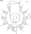
Fig. 2 is a top view of the liquid application unit shown inFig. 1 . -
Fig. 3 is a front view showing an application needle unit in the liquid application unit shown inFig. 1 . -
Fig. 4 is a side view of the application needle unit shown inFig. 3 . -
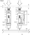
Fig. 5(a) is a front view showing the first state of the application needle unit shown inFig. 3 , andFig. 5(b) is a side view of the application needle unit shown inFig. 5(a) . -
Fig. 6(a) is a front view showing the second state of the application needle unit shown inFig. 3 , andFig. 6(b) is a side view of the application needle unit shown inFig. 6(a) . -
Fig. 7(a) is a front view showing the second state of the application needle unit shown inFig. 3 , andFig. 7(b) is a side view of the application needle unit shown inFig. 7(a) . -
Fig. 8 is a perspective view showing a liquid application apparatus according to the present embodiment. -
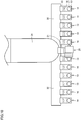
Fig. 9 is a front view showing a modification of the liquid application unit according to the present embodiment. -
Fig. 10 is a top view of the liquid application unit shown inFig. 9 . -
Fig. 11 is a front view showing a modification of the liquid application unit according to the present embodiment. - The embodiments of the present invention will be hereinafter described with reference to the accompanying drawings, in which the same or corresponding components are designated by the same reference characters, and the description thereof will not be repeated.
- As shown in
Figs. 1 and2 , aliquid application unit 100 according to the present embodiment includes a plurality ofapplication needle units 10 and onefirst driving unit 20. - As shown in
Figs. 1 and2 , each of the plurality ofapplication needle units 10 includes: anapplication needle 1; and aliquid material container 2 in which a liquid material is stored and from which the liquid material is supplied toapplication needle 1. - As shown in
Figs. 1 and2 ,first driving unit 20 movesapplication needle 1 in the first direction relative to a substrate 140 (seeFig. 5 ) as a target to which the liquid material is applied andliquid material container 2. The first direction may be any direction, but may be the gravity direction, for example.First driving unit 20 includes aservo motor 3 as a driving source, for example, acam member 5, abearing 6, aconnection member 7, and amovable unit 8.Cam member 5 is attached to arotation member 4 ofservo motor 3 and rotated about the rotation axis ofrotation member 4 together withrotation member 4. The rotation axis ofrotation member 4 is located to extend in the first direction.Cam member 5 has a surface that is located on the side ofservo motor 3 and that is formed as an annular cam surface disposed tosurround rotation member 4. The cam surface has: two surface portions, for example, that are orthogonal to the first direction and that are different in distance fromservo motor 3 in the first direction; and two surface portions that cross the first direction and that connect the above-mentioned two surface portions. The cam surface is in contact with the outer circumferential surface of the outer ring ofbearing 6. The inner ring ofbearing 6 is connected tomovable unit 8 viaconnection member 7. Bearing 6,connection member 7 andmovable unit 8 are fixed at their respective positions relative toservo motor 3,rotation member 4 andcam member 5 in the rotation direction ofrotation member 4. Whencam member 5 is rotated byservo motor 3, bearing 6,connection member 7 andmovable unit 8 reciprocate in the first direction. Thereby,liquid application unit 100 can be switched between the first state and the second state. In the first state,application needle unit 10 is not driven byfirst driving unit 20. In the second state,application needle unit 10 is driven byfirst driving unit 20 to bringapplication needle 1 into contact withsubstrate 140 as a target, thereby allowing application of a liquid material thereto. In addition,Figs. 1 to 4 each showliquid application unit 100 in the first state. - As shown in
Figs. 1 and2 , each of the plurality ofapplication needle units 10 includes: a driven portion driven byfirst driving unit 20; and a fixation portion that is not driven byfirst driving unit 20 and that is fixed at the position relative toservo motor 3. - As shown in
Figs. 1 and2 , for example, the driven portion includesapplication needle 1, an applicationneedle support portion 11, a first spring 12 (an elastic portion), a movingportion 13, afirst guide member 14, apassive portion 17, atransmission portion 18, and a second spring 19 (each of which will be described later in detail). The fixation portion includesliquid material container 2, abase portion 15, and a second guide member 16 (a guide portion), for example. - As shown in
Figs. 1 and2 ,liquid application unit 100 further includes acoupling portion 30 that couples the fixation portions of the plurality of respectiveapplication needle units 10.Coupling portion 30 is connected to each ofbase portions 15 of the plurality of respectiveapplication needle units 10, for example, so as to couplebase portions 15 to each other.Coupling portion 30 has a circular outer shape, for example, in a view seen in the first direction. Each of the plurality ofapplication needle units 10 is connected to the outer circumference ofcoupling portion 30, for example. Also, the plurality ofapplication needle units 10 are spaced apart from each other along this outer circumference. Couplingportion 30 is connected tofirst driving unit 20 only throughapplication needle unit 10. In other words, the plurality ofapplication needle units 10 andcoupling portion 30 are integrally attachable to and detachable from first drivingunit 20. - As shown in
Fig. 2 ,liquid application unit 100 further includes asecond driving unit 23 that changes the relative positional relation between the plurality ofapplication needle units 10 and first drivingunit 20.Second driving unit 23 changes the relative positional relation between the plurality ofapplication needle units 10 and first drivingunit 20 in a circumferential direction D1 with respect to the straight line extending in the first direction.Second driving unit 23 includes a servo motor, for example. Couplingportion 30 is attached to the rotation member ofsecond driving unit 23 in an attachable and detachable manner and rotated about the rotation axis of the rotation member together with this rotation member. In a view ofliquid application unit 100 seen in the first direction, the rotation axis ofsecond driving unit 23 is located to coincide with the center ofcoupling portion 30. The rotation axis of this rotation member is located to extend in the first direction. - First driving
unit 20 andsecond driving unit 23 are integrally formed, for example. First drivingunit 20 is connected to asupport portion 22, for example, throughfirst connection portion 21.Second driving unit 23 is connected to supportportion 22. The positional relation offirst driving unit 20 andsecond driving unit 23 relative to supportportion 22 is fixed.Movable unit 8 offirst driving unit 20 is disposed, for example, on the circumference with respect to the rotation axis ofsecond driving unit 23.Support portion 22 is connected to a moving body of a Z-axis table 120 in a liquid application apparatus 200 (which will be described later) through asecond connection portion 24.Second driving unit 23 is connected toapplication needle unit 10 only through first drivingunit 20 orcoupling portion 30. - Thereby, the plurality of
application needle units 10 andcoupling portion 30 are integrally attachable to and detachable from first drivingunit 20 andsecond driving unit 23. - As shown in
Figs. 1 to 4 ,application needle unit 10 includesapplication needle 1, applicationneedle support portion 11,first spring 12, movingportion 13,first guide member 14,base portion 15,second guide member 16,passive portion 17,transmission portion 18, andsecond spring 19. -
Application needle 1 extends in the first direction. One end ofapplication needle 1 in the first direction (the end ofapplication needle 1 located on the side away from servo motor 3) serves as a needle tip that may be brought into contact with substrate 140 (seeFig. 5 ) as a target. The other end ofapplication needle 1 in the first direction is connected to applicationneedle support portion 11 and supported thereby. - One end of application
needle support portion 11 in the first direction (the end of applicationneedle support portion 11 located on the side away from servo motor 3) is connected to the above-mentioned other end ofapplication needle 1 in the first direction. The other end of applicationneedle support portion 11 in the first direction is connected to one end offirst spring 12 in the first direction (the end offirst spring 12 located on the side away from servo motor 3). Applicationneedle support portion 11 is located closer toservo motor 3 in the first direction thanliquid material container 2 is. - The other end of
first spring 12 in the first direction (the end offirst spring 12 located closer to servo motor 3) is connected to the surface (for example, the lower surface) of the other end of movingportion 13 in the first direction (the end of movingportion 13 located closer to servo motor 3), the surface being located on the side away fromservo motor 3.First spring 12 may biasapplication needle 1 and applicationneedle support portion 11 relative to movingportion 13 in the first direction. The spring constant offirst spring 12 may be set, for example, in accordance with the strength ofsubstrate 140. - A
stopper portion 13a is disposed at one end of movingportion 13 in the first direction (the end of movingportion 13 located on the side away from servo motor 3).Stopper portion 13a and the above-mentioned other end of movingportion 13 in the first direction are disposed to face each other with applicationneedle support portion 11 andfirst spring 12 interposed therebetween in the first direction.Stopper portion 13a is disposed such that it faces, in the first direction, the above-mentioned one end of applicationneedle support portion 11 in the first direction.Stopper portion 13a is located more distant fromservo motor 3 in the first direction than applicationneedle support portion 11 is.Stopper portion 13a is located closer toservo motor 3 in the first direction thanliquid material container 2 is.Stopper portion 13a is provided with a through hole (not shown). The through hole has a hole axis extending in the first direction.Application needle 1 is inserted through the through hole ofstopper portion 13a. The through hole ofstopper portion 13a is disposed so as not to interfere withapplication needle 1. - As shown in
Figs. 3 and 4 , the above-mentioned other end of movingportion 13 in the first direction is connected to one end oftransmission portion 18 in the first direction (the end oftransmission portion 18 located on the side away from servo motor 3). - As shown in
Figs. 3 and 4 , in the first state whereapplication needle unit 10 is not driven by first drivingunit 20, the surface (for example, the lower surface) of the above-mentioned one end of applicationneedle support portion 11, which is located on the side away fromservo motor 3, is in contact with the surface (for example, the upper surface) ofstopper portion 13a located closer toservo motor 3. -
First guide member 14 allows movement of applicationneedle support portion 11 relative to movingportion 13 in the first direction.First guide member 14 restricts movement of applicationneedle support portion 11 relative to movingportion 13 in the direction perpendicular to the first direction.First guide member 14 has a plurality of (for example, three) surfaces extending in the first direction. Applicationneedle support portion 11 has a plurality of (for example, three) surfaces that are disposed to face each of the plurality of above-mentioned surfaces offirst guide member 14 in the direction perpendicular to the first direction and to extend in the first direction. The plurality of surfaces offirst guide member 14 include surfaces that face one side and the other side in the direction orthogonal to the first direction. The plurality of surfaces of applicationneedle support portion 11 include surfaces that face one side and the other side in the direction orthogonal to the first direction. - A
container holding portion 15a is disposed at one end ofbase portion 15 in the first direction (the end ofbase portion 15 located on the side away from servo motor 3).Container holding portion 15a and the other end ofbase portion 15 in the first direction are disposed to face each other with movingportion 13 interposed therebetween in the first direction.Container holding portion 15a is disposed to facestopper portion 13a of movingportion 13 in the first direction. The other end ofbase portion 15 in the first direction is disposed to face, in the first direction, the above-mentioned other end of movingportion 13 in the first direction.Container holding portion 15a is located more distant fromservo motor 3 in the first direction than movingportion 13 is. - As shown in
Fig. 4 ,container holding portion 15a is provided with a throughhole 15b. The hole axis of throughhole 15b extends in the first direction.Application needle 1 is inserted through the throughhole 15b ofcontainer holding portion 15a. The through hole ofcontainer holding portion 15a is disposed so as not to interfere withapplication needle 1. -
Container holding portion 15a has a protrudingportion 15c that protrudes to be away fromservo motor 3 in the first direction. Furthermore,container holding portion 15a has amagnet 15d disposed so as to surround protrudingportion 15c. Protrudingportion 15c andmagnet 15d are disposed, for example, so as to surround throughhole 15b. In other words, protrudingportion 15c andmagnet 15d have an annular shape, for example, in a plan view seen in the first direction. - As shown in
Fig. 4 ,liquid material container 2 is provided with: aspace 2a in which a liquid material is stored; and afirst hole 2b and asecond hole 2c through whichapplication needle 1 is inserted intospace 2a.First hole 2b is located more distant from servo motor 3 (closer to substrate 140) thanspace 2a is.Second hole 2c is located on the opposite side offirst hole 2b with respect tospace 2a.Liquid material container 2 is inlaid incontainer holding portion 15a ofbase portion 15 so as to preventfirst hole 2b andsecond hole 2c from interfering withapplication needle 1 in the plane surface crossing the first direction. - The other end of
base portion 15 in the first direction (the end ofbase portion 15 located on the side closer to servo motor 3) is provided with a through hole (not shown). The hole axis of the through hole extends in the first direction.Transmission portion 18 is inserted through the through hole ofbase portion 15. The through hole ofbase portion 15 is located so as not to interfere withtransmission portion 18. -
Second guide member 16 allows movement of movingportion 13 relative tobase portion 15 in the first direction.Second guide member 16 restricts movement of movingportion 13 relative tobase portion 15 in the direction perpendicular to the first direction.Second guide member 16 has the same configuration as that offirst guide member 14, for example. In other words,second guide member 16 has a plurality of (for example, three) surfaces extending in the first direction. Movingportion 13 has a plurality of (for example, three) surfaces that are disposed to face each of the plurality of above-mentioned surfaces ofsecond guide member 16 in the direction perpendicular to the first direction and to extend in the first direction. The plurality of surfaces ofsecond guide member 16 include surfaces that face one side and the other side in the direction orthogonal to the first direction. The plurality of surfaces of movingportion 13 include surfaces that face one side and the other side in the direction orthogonal to the first direction. - One end of
passive portion 17 in the first direction (the end ofpassive portion 17 located on the side away from servo motor 3) is connected to the other end oftransmission portion 18 in the first direction (the end oftransmission portion 18 located closer to servo motor 3). The other end ofpassive portion 17 in the first direction (the end ofpassive portion 17 located closer to servo motor 3) is located more distant fromservo motor 3 in the first direction thanmovable unit 8 offirst driving unit 20 is and provided to be able to contactmovable unit 8. In a different point of view, the above-mentioned other end ofpassive portion 17 in the first direction is connected tomovable unit 8 offirst driving unit 20 in an attachable and detachable manner. - One end of
transmission portion 18 in the first direction (the end oftransmission portion 18 located on the side away from servo motor 3) is connected to the above-mentioned other end ofbase portion 15 in the first direction. The other end oftransmission portion 18 in the first direction is connected to the above-mentioned one end ofpassive portion 17 in the first direction. - One end of
second spring 19 in the first direction is connected to the above-mentioned other end ofbase portion 15 in the first direction. The other end ofsecond spring 19 in the first direction is connected to the above-mentioned other end ofpassive portion 17 in the first direction.Second spring 19 may biaspassive portion 17 in the first direction relative tobase portion 15 that is fixed at the position relative tofirst driving unit 20. - First, as shown in
Figs. 5(a) and 5(b) ,application needle unit 10 in the above-mentioned first state shown inFigs. 3 and 4 is disposed at the position where it can apply a liquid material to a prescribed position ofsubstrate 140. Thereby,liquid material container 2,base portion 15 andsecond guide member 16 each serving as a fixation portion ofapplication needle unit 10 are positioned relative tosubstrate 140. - Then, as shown in
Figs. 6(a) and 6(b) , the above-mentioned driven portion ofapplication needle unit 10 is driven by first drivingunit 20, thereby bringingapplication needle 1 into contact withsubstrate 140. Specifically, first drivingunit 20 is first driven such thatmovable unit 8 andpassive portion 17 brought into contact withmovable unit 8 are moved towardsubstrate 140. Movingportion 13 connected topassive portion 17 throughtransmission portion 18 is guided bysecond guide member 16 relative toliquid material container 2 andbase portion 15 that are positioned relative tosubstrate 140, so that movingportion 13 is moved in the first direction towardsubstrate 140. At this time,application needle 1 and applicationneedle support portion 11 are biased byfirst spring 12 towardsubstrate 140 relative to movingportion 13 that moves towardsubstrate 140. Accordingly, inapplication needle unit 10, the relative positional relation amongapplication needle 1, applicationneedle support portion 11,first spring 12, and movingportion 13 in the first state is maintained untilapplication needle 1 comes into contact withsubstrate 140. - In other words, from the first state shown in
Figs. 5(a) and 5(b) to the second state shown inFigs. 6(a) and 6(b) , the moving distance ofapplication needle 1 in the first direction is equal to a moving distance L1 (seeFig. 6 ) ofmovable unit 8 andpassive portion 17 in the first direction. Furthermore, the moving distance ofapplication needle 1 in the first direction is equal to the amount of change in length ofsecond spring 19 in the first direction. - As shown in
Figs. 7(a) and 7(b) ,passive portion 17 in the second state shown inFigs. 6(a) and 6(b) may be further moved bymovable unit 8 towardsubstrate 140. Also in this case, movingportion 13, which is connected throughtransmission portion 18 topassive portion 17, and itsstopper portion 13a are guided bysecond guide member 16 relative toliquid material container 2 andbase portion 15, which are positioned relative tosubstrate 140, so as to be moved in the first direction towardsubstrate 140. At this time,application needle 1 is already in contact withsubstrate 140. Thus,application needle 1 and applicationneedle support portion 11 cannot be moved in the first direction towardsubstrate 140. Accordingly,first spring 12 disposed between applicationneedle support portion 11 and movingportion 13 is compressed. Thereby, also in the case wherepassive portion 17 in the second state is further moved bymovable unit 8 towardsubstrate 140,application needle 1 is not moved immediately in conjunction with this movement. Therefore, damage and breakage ofsubstrate 140 can be prevented. At this time, throughapplication needle 1,substrate 140 receives the elastic force offirst spring 12 in proportion to moving distance L2 ofpassive portion 17 in the second state in the first direction. Accordingly, the spring constant offirst spring 12 only has to be set such that the above-mentioned elastic force is weaker than the force ofapplication needle 1 that may damagesubstrate 140. - Then, a liquid application apparatus 200 according to the present embodiment will be described with reference to
Fig. 8 . Liquid application apparatus 200 includesliquid application unit 100 as described above. Liquid application apparatus 200 includesliquid application unit 100, an observationoptical system 110, aCCD camera 111 connected to observationoptical system 110, a Z-axis table 120, an X-axis table 121, a Y-axis table 122, abase 123, and a controller 130. - Observation
optical system 110 is provided to observe an application position onsubstrate 140 serving as the target to which the liquid material is applied.CCD camera 111 of observationoptical system 110 converts an observed image into an electrical signal.Liquid application unit 100 and observationoptical system 110 are mounted on a moving body of Z-axis table 120. Accordingly,liquid application unit 100 and observationoptical system 110 are supported by Z-axis table 120 to be movable in the Z-axis direction inFig. 8 . Z-axis table 120 is mounted on a moving body of X-axis table 121. Accordingly, Z-axis table 120 is supported by X-axis table 121 to be movable in the X-axis direction inFig. 8 .Substrate 140 serving as the target is installed on a moving body of Y-axis table 122. Accordingly,substrate 140 serving as the target is supported by Y-axis table 122 to be movable in the Y-axis direction inFig. 8 . Y-axis table 122 is disposed on the upper surface ofbase 123. Y-axis table 122 is provided to be movable in the Y-axis direction. It should be noted that the Z-axis direction inFig. 8 corresponds to the gravity direction. - Controller 130 includes an
operation panel 131, amonitor 132, and acontrol computer 133. Controller 130 controlsliquid application unit 100, observationoptical system 110, Z-axis table 120, X-axis table 121, and Y-axis table 122.Operation panel 131 is used to input a command intocontrol computer 133.Monitor 132 displays image data converted byCCD camera 111 of observationoptical system 110, and displays output data fromcontrol computer 133. - Next, a liquid application method performed employing liquid application apparatus 200 will be described. In the liquid application method, first,
substrate 140 as a target to which a liquid material is applied is mounted on Y-axis table 122. The application position insubstrate 140 is then determined. Specifically, X-axis table 121, Y-axis table 122, and Z-axis table 120 are moved such that the application position insubstrate 140 is located directly below observationoptical system 110. The application position insubstrate 140 is observed by observationoptical system 110 and is then determined.Substrate 140 is moved by X-axis table 121, Y-axis table 122, and Z-axis table 120 such that the application position determined in this way is located directly belowliquid application unit 100. Then,liquid application unit 100 applies the liquid material at the determined application position. Then,substrate 140 is moved by X-axis table 121, Y-axis table 122, and Z-axis table 120 such that the next application position is located directly belowliquid application unit 100. After completion of the movement,liquid application unit 100 applies the liquid material. Each of these steps can be repeatedly performed continuously. As a result, by the liquid application method according to the present embodiment, a predetermined circuit pattern can be formed on the upper surface ofsubstrate 140 in a short time. - A
liquid application unit 100 according to the present embodiment is a liquid application unit for applying a liquid material onto a surface of asubstrate 140 as a target using an application needle.Liquid application unit 100 includes: a plurality ofapplication needle units 10 each including anapplication needle 1 and aliquid material container 2 in which the liquid material is stored and from which the liquid material is supplied toapplication needle 1; and afirst driving unit 20 configured to moveapplication needle 1 relative tosubstrate 140 andliquid material container 2 in a first direction. The plurality ofapplication needle units 10 are integrally attachable to and detachable from first drivingunit 20. - In this way, at least either of
application needle 1 and the liquid material can be resupplied or replaced for each of the plurality ofapplication needle units 10 that are separated from first drivingunit 20. Thus, resupply or replacement may be readily performed. Furthermore, inliquid application unit 100, the plurality ofapplication needle units 10 each includingliquid material container 2 storing anew application needle 1 and a new liquid material can also be prepared in advance before replacement. In this way, the plurality ofapplication needle units 10 having been already attached toliquid application unit 100 can be readily and immediately replaced with newapplication needle units 10. -
Liquid application unit 100 further includes asecond driving unit 23 configured to change a relative positional relation between the plurality ofapplication needle units 10 and first drivingunit 20. The plurality ofapplication needle units 10 are integrally attachable to and detachable from first drivingunit 20 andsecond driving unit 23. - In this way,
first driving unit 20 andsecond driving unit 23 can drive onlyapplication needle unit 10 among the plurality ofapplication needle units 10, for example, that is in the prescribed positional relation tofirst driving unit 20. Also, at least either ofapplication needle 1 and the liquid material can be resupplied or replaced for each of the plurality ofapplication needle units 10 that are separated from first drivingunit 20 andsecond driving unit 23. Thus, resupply or replacement may be readily performed. - In
liquid application unit 100, the plurality ofapplication needle units 10 are arranged side by side in an annular shape in a view seen in a first direction D1.Second driving unit 23 is configured to change a relative positional relation between each of the plurality ofapplication needle units 10 and first drivingunit 20. - In this way, second driving unit 23 (for example, the servo motor) may readily change the positions of the plurality of
application needle units 10, which are disposed along circumferential direction D1, relative tofirst driving unit 20. Thus, according toliquid application unit 100, first drivingunit 20 andsecond driving unit 23 can drive onlyapplication needle unit 10 among the plurality ofapplication needle units 10, for example, that is in the prescribed positional relation tofirst driving unit 20. - In
liquid application unit 100, each of the plurality ofapplication needle units 10 further includes: afirst spring 12 as an elastic portion that is capable of biasingapplication needle 1 in the first direction; a movingportion 13 that is connected toapplication needle 1 throughfirst spring 12 and moved by first drivingunit 20 relative tosubstrate 140; abase portion 15 that is fixed tofirst driving unit 20; and asecond guide member 16 serving as a guide portion and configured to allow movement of movingportion 13 relative tobase portion 15 in the first direction and configured to restrict movement of movingportion 13 relative tobase portion 15 in a direction orthogonal to the first direction.Liquid application unit 100 further includes acoupling portion 30 configured to couple a plurality ofbase portions 15 of the plurality ofapplication needle units 10.Second driving unit 23 is configured to drivecoupling portion 30 to change the relative positional relation between the plurality ofapplication needle units 10 and first drivingunit 20. The plurality ofapplication needle units 10 andcoupling portion 30 are integrally attachable to and detachable from first drivingunit 20 andsecond driving unit 23. - In this way, when moving
portion 13 in the second state is further moved by first drivingunit 20 towardsubstrate 140,application needle 1 cannot be moved towardsubstrate 140 sinceapplication needle 1 is in contact withsubstrate 140. Thus,first spring 12 is compressed. Accordingly, in the case as described above,application needle 1 does not move immediately in conjunction with movingportion 13. Therefore, damage and breakage ofsubstrate 140 can be prevented. - In
liquid application unit 100,liquid material container 2 is supported so as to be attachable to and detachable frombase portion 15. - In this way, only the liquid material can be readily replaced.
- In
liquid application unit 100,liquid material container 2 is provided with: aspace 2a in which the liquid material is stored; and afirst hole 2b and asecond hole 2c through whichapplication needle 1 is inserted intospace 2a.First hole 2b is located closer to the target thanspace 2a is.Second hole 2c is located on an opposite side offirst hole 2b with respect tospace 2a. A part ofliquid material container 2 is inlaid in a part ofbase portion 15 so as to preventfirst hole 2b andsecond hole 2c from interfering withapplication needle 1. - In this way,
application needle 1 andliquid material container 2 can be readily positioned so as to preventapplication needle 1 from interfering withfirst hole 2b andsecond hole 2c ofliquid material container 2. - Furthermore, according to
liquid application unit 100, also whencontainer holding portion 15a has amagnet 15d, and when a relatively large magnetic attraction force acts betweenliquid material container 2 andcontainer holding portion 15a,liquid material container 2 can be readily and highly accurately aligned withcontainer holding portion 15a since a part ofliquid material container 2 is inlaid in a part ofbase portion 15.Liquid application unit 100 as described above includes a liquid material container in which a large amount of liquid material is stored, and thus, suitable to a liquid application apparatus capable of applying a liquid material continuously for a long time. - Liquid application apparatus 200 according to the present embodiment includes: the above-mentioned
liquid application unit 100; and a Y-axis table 122 configured to holdsubstrate 140 as a target and serving as a holding base. - Liquid application apparatus 200 as described above includes
liquid application unit 100, for which at least either of the plurality of application needles 1 and the plurality of liquid materials may be readily resupplied or replaced. Therefore, according to liquid application apparatus 200, at least either of the plurality of application needles 1 and the plurality of liquid materials may be readily resupplied or replaced as compared with the conventional liquid application apparatus. - As shown in
Figs. 9 and10 ,liquid application unit 100 as described above may include asecond driving unit 23 that can change the relative positional relation between the plurality ofapplication needle units 10 and first drivingunit 20 in a second direction D2 that is orthogonal to the first direction. -
Second driving unit 23 includes a linear motor, for example. The linear motor includes a fixation portion extending in second direction D2 along the horizontal direction, for example, and a movable unit that is guided by the fixation portion so as to be linearly moved in second direction D2. The movable unit is attached to acoupling portion 32 that extends in second direction D2.Second driving unit 23 is connected to a moving body of a Z-axis table 120 in a liquid application apparatus 200 (described later) through asecond connection portion 24. In other words, inliquid application unit 100 as described above, the plurality ofapplication needle units 10 may be arranged side by side in second direction D2 that is orthogonal to first direction D1.Second driving unit 23 changes the relative positional relation between each of the plurality ofapplication needle units 10 and first drivingunit 20. - Also in this way, second driving unit 23 (for example, a linear motor) may readily change the position of each of the plurality of
application needle units 10, which are disposed in second direction D2, relative tofirst driving unit 20. Thus, according toliquid application unit 100, first drivingunit 20 andsecond driving unit 23 can drive onlyapplication needle unit 10 among the plurality ofapplication needle units 10, for example, that is in a prescribed positional relation tofirst driving unit 20. -
Liquid application unit 100 may be configured such that the plurality ofapplication needle units 10 can be integrally driven by first drivingunit 20. For example,movable unit 8 offirst driving unit 20 may be able to press each ofpassive portions 17 in their respectiveapplication needle units 10. In the case where the plurality ofapplication needle units 10 are arranged side by side in an annular shape as shown inFig. 11 ,movable unit 8 has an annular shape in a plan view see in the first direction, for example. In the case where the plurality ofapplication needle units 10 are arranged linearly,movable unit 8 has a rectangular shape in a plan view seen in the first direction. In a different point of view,liquid application unit 100 does not need to includesecond driving unit 23. Also in suchliquid application unit 100, as long as the plurality ofapplication needle units 10 are integrally attachable to and detachable from first drivingunit 20, at least either ofapplication needle 1 and the liquid material can be resupplied or replaced for each of the plurality ofapplication needle units 10 that are separated from first drivingunit 20. Accordingly, resupply or replacement as described above may be readily performed also inliquid application unit 100. - It should be understood that the embodiments disclosed herein are illustrative and non-restrictive in every respect. The scope of the present invention is defined by the terms of the claims, rather than the description above, and is intended to include any modifications within the meaning and scope equivalent to the terms of the claims.
- The present invention is particularly advantageously applied to a liquid application unit including a plurality of application needles and a plurality of liquid material containers, and to a liquid material application apparatus including this liquid application unit.
- 1 application needle, 2 liquid material container, 2a space, 2b first hole, 2c second hole, 3 servo motor, 4 rotation member, 5 cam member, 6 bearing, 7 connection member, 8 movable unit, 10 application needle unit, 11 application needle support portion, 12 first spring, 13 moving portion, 13a stopper portion, 14 first guide member, 15 base portion, 15a container holding portion, 15b through hole, 15c protruding portion, 15d magnet, 16 second guide member, 17 passive portion, 18 transmission portion, 19 second spring, 20 first driving unit, 21 first connection portion, 22 support portion, 23 second driving unit, 24 second connection portion, 30, 32 coupling portion, 100 liquid application unit, 110 observation optical system, 111 camera, 120, 121, 122 axis table, 123 base, 130 controller, 131 operation panel, 132 monitor, 133 control computer, 140 substrate, 200 liquid application apparatus.
Claims (8)
- A liquid application unit for applying a liquid material onto a surface of a target using an application needle, the liquid application unit comprising:a plurality of application needle units each including the application needle and a liquid material container in which the liquid material is stored and from which the liquid material is supplied to the application needle; anda first driving unit configured to move the application needle relative to the target and the liquid material container in a first direction,the plurality of application needle units being integrally attachable to and detachable from the first driving unit.
- The liquid application unit according to claim 1, further comprising a second driving unit configured to change a relative positional relation between the plurality of application needle units and the first driving unit, wherein
the plurality of application needle units are integrally attachable to and detachable from the first driving unit and the second driving unit. - The liquid application unit according to claim 2, wherein
the plurality of application needle units are arranged side by side in a second direction that is orthogonal to the first direction, and
the second driving unit is configured to change a relative positional relation between each of the plurality of application needle units and the first driving unit. - The liquid application unit according to claim 2, wherein
the plurality of application needle units are arranged side by side in an annular shape in a view seen in the first direction, and
the second driving unit is configured to change a relative positional relation between each of the plurality of application needle units and the first driving unit. - The liquid application unit according to any one of claims 2 to 4, wherein each of the plurality of application needle units includesan elastic portion that is capable of biasing the application needle in the first direction,a moving portion that is connected to the application needle through the elastic portion, and moved by the first driving unit relative to the target,a base portion that is fixed to the first driving unit, anda guide portion configured toallow movement of the moving portion relative to the base portion in the first direction, andrestrict movement of the moving portion relative to the base portion in a direction orthogonal to the first direction,the liquid application unit further comprises a coupling portion configured to couple a plurality of the base portions of the plurality of application needle units,
the second driving unit is configured to drive the coupling portion to change the relative positional relation between the plurality of application needle units and the first driving unit, and
the plurality of application needle units and the coupling portion are integrally attachable to and detachable from the first driving unit and the second driving unit. - The liquid application unit according to claim 5, wherein the liquid material container is supported so as to be attachable to and detachable from the base portion.
- The liquid application unit according to claim 6, wherein
the liquid material container is provided with:a space in which the liquid material is stored; anda first hole and a second hole through which the application needle is inserted into the space,the first hole is located closer to the target than the space is,
the second hole is located on an opposite side of the first hole with respect to the space, and
a part of the liquid material container is inlaid in a part of the base portion so as to prevent the first hole and the second hole from interfering with the application needle. - A liquid application apparatus comprising:the liquid application unit according to any one of claims 1 to 7; anda holding base configured to hold the target.
Applications Claiming Priority (2)
| Application Number | Priority Date | Filing Date | Title |
|---|---|---|---|
| JP2017034957A JP2018140336A (en) | 2017-02-27 | 2017-02-27 | Liquid coating unit and liquid coating device |
| PCT/JP2018/006575 WO2018155589A1 (en) | 2017-02-27 | 2018-02-22 | Liquid application unit and liquid application device |
Publications (3)
| Publication Number | Publication Date |
|---|---|
| EP3590607A1 true EP3590607A1 (en) | 2020-01-08 |
| EP3590607A4 EP3590607A4 (en) | 2021-01-13 |
| EP3590607B1 EP3590607B1 (en) | 2025-08-20 |
Family
ID=63252704
Family Applications (1)
| Application Number | Title | Priority Date | Filing Date |
|---|---|---|---|
| EP18756923.1A Active EP3590607B1 (en) | 2017-02-27 | 2018-02-22 | Liquid application unit and liquid application apparatus |
Country Status (5)
| Country | Link |
|---|---|
| US (1) | US11478813B2 (en) |
| EP (1) | EP3590607B1 (en) |
| JP (1) | JP2018140336A (en) |
| CN (1) | CN110337334A (en) |
| WO (1) | WO2018155589A1 (en) |
Families Citing this family (4)
| Publication number | Priority date | Publication date | Assignee | Title |
|---|---|---|---|---|
| JP7346073B2 (en) * | 2019-04-26 | 2023-09-19 | Ntn株式会社 | Coating mechanism and coating device |
| FR3113848B1 (en) * | 2020-09-07 | 2023-06-16 | Exel Ind | Device for applying a product, machine comprising such a device and method for controlling such a machine |
| CN112827738B (en) * | 2021-01-15 | 2021-12-31 | 江苏神铸智能科技有限公司 | Garbage bin oral area all-in-one of coloring |
| CN117341360B (en) * | 2023-10-26 | 2025-09-23 | 杭州宏华数码科技股份有限公司 | Printing units and printing systems |
Family Cites Families (8)
| Publication number | Priority date | Publication date | Assignee | Title |
|---|---|---|---|---|
| JP4767708B2 (en) | 2005-03-28 | 2011-09-07 | Ntn株式会社 | Coating unit and pattern correction device |
| JP4767567B2 (en) | 2005-03-28 | 2011-09-07 | Ntn株式会社 | Pattern correction device |
| JP4719050B2 (en) | 2006-03-30 | 2011-07-06 | Ntn株式会社 | Pattern correction device and application unit thereof |
| JP4883535B2 (en) | 2007-11-27 | 2012-02-22 | レーザーテック株式会社 | Defect correction apparatus, defect correction method, and pattern substrate manufacturing method |
| FR2929859B1 (en) | 2008-04-11 | 2012-10-19 | Dioscure | DEVICE AND METHOD FOR FORMING MICRO DEPOTS. |
| JP6411735B2 (en) | 2013-12-13 | 2018-10-24 | Ntn株式会社 | Application member, application device, and application method |
| JP6381902B2 (en) * | 2013-12-13 | 2018-08-29 | Ntn株式会社 | Application needle holder |
| JP2016049524A (en) | 2014-09-02 | 2016-04-11 | Ntn株式会社 | Liquid coating unit, and liquid coating device |
-
2017
- 2017-02-27 JP JP2017034957A patent/JP2018140336A/en active Pending
-
2018
- 2018-02-22 CN CN201880013944.9A patent/CN110337334A/en active Pending
- 2018-02-22 EP EP18756923.1A patent/EP3590607B1/en active Active
- 2018-02-22 WO PCT/JP2018/006575 patent/WO2018155589A1/en not_active Ceased
- 2018-02-22 US US16/488,915 patent/US11478813B2/en active Active
Also Published As
| Publication number | Publication date |
|---|---|
| CN110337334A (en) | 2019-10-15 |
| WO2018155589A1 (en) | 2018-08-30 |
| EP3590607B1 (en) | 2025-08-20 |
| US20200038900A1 (en) | 2020-02-06 |
| US11478813B2 (en) | 2022-10-25 |
| JP2018140336A (en) | 2018-09-13 |
| EP3590607A4 (en) | 2021-01-13 |
Similar Documents
| Publication | Publication Date | Title |
|---|---|---|
| EP3590607B1 (en) | Liquid application unit and liquid application apparatus | |
| US8944001B2 (en) | Automated position locator for a height sensor in a dispensing system | |
| US20160089792A1 (en) | Magnetically Attached End Effectors | |
| CN109952015B (en) | Auxiliary device and method for determining configuration of lower support pin | |
| EP3381569B1 (en) | Application unit, application apparatus, and method for manufacturing object to which matereal is applied | |
| JP6381902B2 (en) | Application needle holder | |
| JP2015112576A (en) | Application member, application device, and application method | |
| US10845185B2 (en) | Measuring apparatus and method for measuring film thickness using relative heights in combination with refractive index | |
| JP4719050B2 (en) | Pattern correction device and application unit thereof | |
| US11511311B2 (en) | Application mechanism and application apparatus | |
| EP3409375B1 (en) | APPLICATION MECHANISM AND METHOD FOR MANUFACTURING AN OBJECT TO
WHICH AN APPLICATION MATERIAL IS APPLIED | |
| JP6794187B2 (en) | Liquid coating unit and liquid coating device | |
| EP4299195A1 (en) | Coating mechanism and coating apparatus | |
| US6618147B1 (en) | Aligning device for assembling microsystems | |
| KR101280643B1 (en) | Pattern amendment device and application unit thereof | |
| US20090206970A1 (en) | Device for coupling an attachment | |
| KR101773556B1 (en) | The position alignment device and the method using the same | |
| CN120791416A (en) | Watchcase assembly line body and wristband device assembly bus | |
| JP2013205816A (en) | Stage and microscope | |
| KR20130051841A (en) | Apparatus and method for alignment | |
| KR20190133585A (en) | Apparatus for testing micro light element | |
| JP2008272931A (en) | Apparatus and method for controlling exercise apparatus |
Legal Events
| Date | Code | Title | Description |
|---|---|---|---|
| STAA | Information on the status of an ep patent application or granted ep patent |
Free format text: STATUS: THE INTERNATIONAL PUBLICATION HAS BEEN MADE |
|
| PUAI | Public reference made under article 153(3) epc to a published international application that has entered the european phase |
Free format text: ORIGINAL CODE: 0009012 |
|
| STAA | Information on the status of an ep patent application or granted ep patent |
Free format text: STATUS: REQUEST FOR EXAMINATION WAS MADE |
|
| 17P | Request for examination filed |
Effective date: 20190926 |
|
| AK | Designated contracting states |
Kind code of ref document: A1 Designated state(s): AL AT BE BG CH CY CZ DE DK EE ES FI FR GB GR HR HU IE IS IT LI LT LU LV MC MK MT NL NO PL PT RO RS SE SI SK SM TR |
|
| AX | Request for extension of the european patent |
Extension state: BA ME |
|
| DAV | Request for validation of the european patent (deleted) | ||
| DAX | Request for extension of the european patent (deleted) | ||
| A4 | Supplementary search report drawn up and despatched |
Effective date: 20201216 |
|
| RIC1 | Information provided on ipc code assigned before grant |
Ipc: B05C 5/02 20060101ALI20201210BHEP Ipc: B05C 1/02 20060101AFI20201210BHEP Ipc: B05C 11/10 20060101ALI20201210BHEP |
|
| STAA | Information on the status of an ep patent application or granted ep patent |
Free format text: STATUS: EXAMINATION IS IN PROGRESS |
|
| 17Q | First examination report despatched |
Effective date: 20240321 |
|
| GRAJ | Information related to disapproval of communication of intention to grant by the applicant or resumption of examination proceedings by the epo deleted |
Free format text: ORIGINAL CODE: EPIDOSDIGR1 |
|
| GRAP | Despatch of communication of intention to grant a patent |
Free format text: ORIGINAL CODE: EPIDOSNIGR1 |
|
| GRAP | Despatch of communication of intention to grant a patent |
Free format text: ORIGINAL CODE: EPIDOSNIGR1 |
|
| STAA | Information on the status of an ep patent application or granted ep patent |
Free format text: STATUS: GRANT OF PATENT IS INTENDED |
|
| INTG | Intention to grant announced |
Effective date: 20250313 |
|
| GRAS | Grant fee paid |
Free format text: ORIGINAL CODE: EPIDOSNIGR3 |
|
| GRAA | (expected) grant |
Free format text: ORIGINAL CODE: 0009210 |
|
| STAA | Information on the status of an ep patent application or granted ep patent |
Free format text: STATUS: THE PATENT HAS BEEN GRANTED |
|
| AK | Designated contracting states |
Kind code of ref document: B1 Designated state(s): AL AT BE BG CH CY CZ DE DK EE ES FI FR GB GR HR HU IE IS IT LI LT LU LV MC MK MT NL NO PL PT RO RS SE SI SK SM TR |
|
| REG | Reference to a national code |
Ref country code: GB Ref legal event code: FG4D |
|
| REG | Reference to a national code |
Ref country code: CH Ref legal event code: EP |
|
| REG | Reference to a national code |
Ref country code: IE Ref legal event code: FG4D |
|
| REG | Reference to a national code |
Ref country code: DE Ref legal event code: R096 Ref document number: 602018084766 Country of ref document: DE |
|
| REG | Reference to a national code |
Ref country code: NL Ref legal event code: MP Effective date: 20250820 |
|
| PG25 | Lapsed in a contracting state [announced via postgrant information from national office to epo] |
Ref country code: IS Free format text: LAPSE BECAUSE OF FAILURE TO SUBMIT A TRANSLATION OF THE DESCRIPTION OR TO PAY THE FEE WITHIN THE PRESCRIBED TIME-LIMIT Effective date: 20251220 |
|
| PG25 | Lapsed in a contracting state [announced via postgrant information from national office to epo] |
Ref country code: NO Free format text: LAPSE BECAUSE OF FAILURE TO SUBMIT A TRANSLATION OF THE DESCRIPTION OR TO PAY THE FEE WITHIN THE PRESCRIBED TIME-LIMIT Effective date: 20251120 |
|
| REG | Reference to a national code |
Ref country code: LT Ref legal event code: MG9D |
|
| PG25 | Lapsed in a contracting state [announced via postgrant information from national office to epo] |
Ref country code: PT Free format text: LAPSE BECAUSE OF FAILURE TO SUBMIT A TRANSLATION OF THE DESCRIPTION OR TO PAY THE FEE WITHIN THE PRESCRIBED TIME-LIMIT Effective date: 20251222 |
|
| PG25 | Lapsed in a contracting state [announced via postgrant information from national office to epo] |
Ref country code: FI Free format text: LAPSE BECAUSE OF FAILURE TO SUBMIT A TRANSLATION OF THE DESCRIPTION OR TO PAY THE FEE WITHIN THE PRESCRIBED TIME-LIMIT Effective date: 20250820 |
|
| PG25 | Lapsed in a contracting state [announced via postgrant information from national office to epo] |
Ref country code: NL Free format text: LAPSE BECAUSE OF FAILURE TO SUBMIT A TRANSLATION OF THE DESCRIPTION OR TO PAY THE FEE WITHIN THE PRESCRIBED TIME-LIMIT Effective date: 20250820 Ref country code: HR Free format text: LAPSE BECAUSE OF FAILURE TO SUBMIT A TRANSLATION OF THE DESCRIPTION OR TO PAY THE FEE WITHIN THE PRESCRIBED TIME-LIMIT Effective date: 20250820 |
|
| PG25 | Lapsed in a contracting state [announced via postgrant information from national office to epo] |
Ref country code: GR Free format text: LAPSE BECAUSE OF FAILURE TO SUBMIT A TRANSLATION OF THE DESCRIPTION OR TO PAY THE FEE WITHIN THE PRESCRIBED TIME-LIMIT Effective date: 20251121 |
|
| PG25 | Lapsed in a contracting state [announced via postgrant information from national office to epo] |
Ref country code: SE Free format text: LAPSE BECAUSE OF FAILURE TO SUBMIT A TRANSLATION OF THE DESCRIPTION OR TO PAY THE FEE WITHIN THE PRESCRIBED TIME-LIMIT Effective date: 20250820 |
|
| PG25 | Lapsed in a contracting state [announced via postgrant information from national office to epo] |
Ref country code: LV Free format text: LAPSE BECAUSE OF FAILURE TO SUBMIT A TRANSLATION OF THE DESCRIPTION OR TO PAY THE FEE WITHIN THE PRESCRIBED TIME-LIMIT Effective date: 20250820 |
|
| PG25 | Lapsed in a contracting state [announced via postgrant information from national office to epo] |
Ref country code: BG Free format text: LAPSE BECAUSE OF FAILURE TO SUBMIT A TRANSLATION OF THE DESCRIPTION OR TO PAY THE FEE WITHIN THE PRESCRIBED TIME-LIMIT Effective date: 20250820 Ref country code: PL Free format text: LAPSE BECAUSE OF FAILURE TO SUBMIT A TRANSLATION OF THE DESCRIPTION OR TO PAY THE FEE WITHIN THE PRESCRIBED TIME-LIMIT Effective date: 20250820 |
|
| PG25 | Lapsed in a contracting state [announced via postgrant information from national office to epo] |
Ref country code: RS Free format text: LAPSE BECAUSE OF FAILURE TO SUBMIT A TRANSLATION OF THE DESCRIPTION OR TO PAY THE FEE WITHIN THE PRESCRIBED TIME-LIMIT Effective date: 20251120 |
|
| PG25 | Lapsed in a contracting state [announced via postgrant information from national office to epo] |
Ref country code: ES Free format text: LAPSE BECAUSE OF FAILURE TO SUBMIT A TRANSLATION OF THE DESCRIPTION OR TO PAY THE FEE WITHIN THE PRESCRIBED TIME-LIMIT Effective date: 20250820 |
|
| REG | Reference to a national code |
Ref country code: AT Ref legal event code: MK05 Ref document number: 1826781 Country of ref document: AT Kind code of ref document: T Effective date: 20250820 |
|
| PG25 | Lapsed in a contracting state [announced via postgrant information from national office to epo] |
Ref country code: SM Free format text: LAPSE BECAUSE OF FAILURE TO SUBMIT A TRANSLATION OF THE DESCRIPTION OR TO PAY THE FEE WITHIN THE PRESCRIBED TIME-LIMIT Effective date: 20250820 |
|
| PG25 | Lapsed in a contracting state [announced via postgrant information from national office to epo] |
Ref country code: DK Free format text: LAPSE BECAUSE OF FAILURE TO SUBMIT A TRANSLATION OF THE DESCRIPTION OR TO PAY THE FEE WITHIN THE PRESCRIBED TIME-LIMIT Effective date: 20250820 |
|
| PG25 | Lapsed in a contracting state [announced via postgrant information from national office to epo] |
Ref country code: AT Free format text: LAPSE BECAUSE OF FAILURE TO SUBMIT A TRANSLATION OF THE DESCRIPTION OR TO PAY THE FEE WITHIN THE PRESCRIBED TIME-LIMIT Effective date: 20250820 |
|
| PG25 | Lapsed in a contracting state [announced via postgrant information from national office to epo] |
Ref country code: IT Free format text: LAPSE BECAUSE OF FAILURE TO SUBMIT A TRANSLATION OF THE DESCRIPTION OR TO PAY THE FEE WITHIN THE PRESCRIBED TIME-LIMIT Effective date: 20250820 |
|
| PGFP | Annual fee paid to national office [announced via postgrant information from national office to epo] |
Ref country code: FR Payment date: 20260219 Year of fee payment: 9 |
|
| PG25 | Lapsed in a contracting state [announced via postgrant information from national office to epo] |
Ref country code: CZ Free format text: LAPSE BECAUSE OF FAILURE TO SUBMIT A TRANSLATION OF THE DESCRIPTION OR TO PAY THE FEE WITHIN THE PRESCRIBED TIME-LIMIT Effective date: 20250820 |
|
| PG25 | Lapsed in a contracting state [announced via postgrant information from national office to epo] |
Ref country code: EE Free format text: LAPSE BECAUSE OF FAILURE TO SUBMIT A TRANSLATION OF THE DESCRIPTION OR TO PAY THE FEE WITHIN THE PRESCRIBED TIME-LIMIT Effective date: 20250820 Ref country code: SK Free format text: LAPSE BECAUSE OF FAILURE TO SUBMIT A TRANSLATION OF THE DESCRIPTION OR TO PAY THE FEE WITHIN THE PRESCRIBED TIME-LIMIT Effective date: 20250820 |