EP3590606A1 - Offset masking device and method - Google Patents
Offset masking device and method Download PDFInfo
- Publication number
- EP3590606A1 EP3590606A1 EP19184256.6A EP19184256A EP3590606A1 EP 3590606 A1 EP3590606 A1 EP 3590606A1 EP 19184256 A EP19184256 A EP 19184256A EP 3590606 A1 EP3590606 A1 EP 3590606A1
- Authority
- EP
- European Patent Office
- Prior art keywords
- edge
- masking body
- mask
- projection
- standoff
- Prior art date
- Legal status (The legal status is an assumption and is not a legal conclusion. Google has not performed a legal analysis and makes no representation as to the accuracy of the status listed.)
- Withdrawn
Links
- 230000000873 masking effect Effects 0.000 title claims abstract description 104
- 238000000034 method Methods 0.000 title claims description 12
- 238000000576 coating method Methods 0.000 claims description 64
- 239000011248 coating agent Substances 0.000 claims description 55
- 239000000758 substrate Substances 0.000 claims description 33
- 239000010410 layer Substances 0.000 claims description 14
- 239000012530 fluid Substances 0.000 claims description 8
- 239000000463 material Substances 0.000 claims description 7
- 239000006260 foam Substances 0.000 claims description 4
- 239000012790 adhesive layer Substances 0.000 claims description 3
- 239000007921 spray Substances 0.000 description 7
- 239000000853 adhesive Substances 0.000 description 1
- 230000001070 adhesive effect Effects 0.000 description 1
- 230000008901 benefit Effects 0.000 description 1
- 239000000567 combustion gas Substances 0.000 description 1
- 230000007423 decrease Effects 0.000 description 1
- 238000009792 diffusion process Methods 0.000 description 1
- 230000004048 modification Effects 0.000 description 1
- 238000012986 modification Methods 0.000 description 1
- 238000004806 packaging method and process Methods 0.000 description 1
- 230000008439 repair process Effects 0.000 description 1
- 238000000926 separation method Methods 0.000 description 1
- 238000005507 spraying Methods 0.000 description 1
- 230000007704 transition Effects 0.000 description 1
Images



Classifications
-
- B—PERFORMING OPERATIONS; TRANSPORTING
- B05—SPRAYING OR ATOMISING IN GENERAL; APPLYING FLUENT MATERIALS TO SURFACES, IN GENERAL
- B05B—SPRAYING APPARATUS; ATOMISING APPARATUS; NOZZLES
- B05B12/00—Arrangements for controlling delivery; Arrangements for controlling the spray area
- B05B12/16—Arrangements for controlling delivery; Arrangements for controlling the spray area for controlling the spray area
- B05B12/20—Masking elements, i.e. elements defining uncoated areas on an object to be coated
- B05B12/24—Masking elements, i.e. elements defining uncoated areas on an object to be coated made at least partly of flexible material, e.g. sheets of paper or fabric
-
- B—PERFORMING OPERATIONS; TRANSPORTING
- B05—SPRAYING OR ATOMISING IN GENERAL; APPLYING FLUENT MATERIALS TO SURFACES, IN GENERAL
- B05D—PROCESSES FOR APPLYING FLUENT MATERIALS TO SURFACES, IN GENERAL
- B05D1/00—Processes for applying liquids or other fluent materials
- B05D1/32—Processes for applying liquids or other fluent materials using means for protecting parts of a surface not to be coated, e.g. using stencils, resists
- B05D1/322—Removable films used as masks
- B05D1/325—Masking layer made of peelable film
-
- B—PERFORMING OPERATIONS; TRANSPORTING
- B05—SPRAYING OR ATOMISING IN GENERAL; APPLYING FLUENT MATERIALS TO SURFACES, IN GENERAL
- B05C—APPARATUS FOR APPLYING FLUENT MATERIALS TO SURFACES, IN GENERAL
- B05C21/00—Accessories or implements for use in connection with applying liquids or other fluent materials to surfaces, not provided for in groups B05C1/00 - B05C19/00
- B05C21/005—Masking devices
-
- B—PERFORMING OPERATIONS; TRANSPORTING
- B05—SPRAYING OR ATOMISING IN GENERAL; APPLYING FLUENT MATERIALS TO SURFACES, IN GENERAL
- B05D—PROCESSES FOR APPLYING FLUENT MATERIALS TO SURFACES, IN GENERAL
- B05D1/00—Processes for applying liquids or other fluent materials
- B05D1/02—Processes for applying liquids or other fluent materials performed by spraying
- B05D1/12—Applying particulate materials
-
- C—CHEMISTRY; METALLURGY
- C23—COATING METALLIC MATERIAL; COATING MATERIAL WITH METALLIC MATERIAL; CHEMICAL SURFACE TREATMENT; DIFFUSION TREATMENT OF METALLIC MATERIAL; COATING BY VACUUM EVAPORATION, BY SPUTTERING, BY ION IMPLANTATION OR BY CHEMICAL VAPOUR DEPOSITION, IN GENERAL; INHIBITING CORROSION OF METALLIC MATERIAL OR INCRUSTATION IN GENERAL
- C23C—COATING METALLIC MATERIAL; COATING MATERIAL WITH METALLIC MATERIAL; SURFACE TREATMENT OF METALLIC MATERIAL BY DIFFUSION INTO THE SURFACE, BY CHEMICAL CONVERSION OR SUBSTITUTION; COATING BY VACUUM EVAPORATION, BY SPUTTERING, BY ION IMPLANTATION OR BY CHEMICAL VAPOUR DEPOSITION, IN GENERAL
- C23C4/00—Coating by spraying the coating material in the molten state, e.g. by flame, plasma or electric discharge
- C23C4/01—Selective coating, e.g. pattern coating, without pre-treatment of the material to be coated
-
- F—MECHANICAL ENGINEERING; LIGHTING; HEATING; WEAPONS; BLASTING
- F01—MACHINES OR ENGINES IN GENERAL; ENGINE PLANTS IN GENERAL; STEAM ENGINES
- F01D—NON-POSITIVE DISPLACEMENT MACHINES OR ENGINES, e.g. STEAM TURBINES
- F01D5/00—Blades; Blade-carrying members; Heating, heat-insulating, cooling or antivibration means on the blades or the members
- F01D5/12—Blades
- F01D5/28—Selecting particular materials; Particular measures relating thereto; Measures against erosion or corrosion
- F01D5/288—Protective coatings for blades
-
- F—MECHANICAL ENGINEERING; LIGHTING; HEATING; WEAPONS; BLASTING
- F05—INDEXING SCHEMES RELATING TO ENGINES OR PUMPS IN VARIOUS SUBCLASSES OF CLASSES F01-F04
- F05D—INDEXING SCHEME FOR ASPECTS RELATING TO NON-POSITIVE-DISPLACEMENT MACHINES OR ENGINES, GAS-TURBINES OR JET-PROPULSION PLANTS
- F05D2220/00—Application
- F05D2220/40—Application in turbochargers
-
- F—MECHANICAL ENGINEERING; LIGHTING; HEATING; WEAPONS; BLASTING
- F05—INDEXING SCHEMES RELATING TO ENGINES OR PUMPS IN VARIOUS SUBCLASSES OF CLASSES F01-F04
- F05D—INDEXING SCHEME FOR ASPECTS RELATING TO NON-POSITIVE-DISPLACEMENT MACHINES OR ENGINES, GAS-TURBINES OR JET-PROPULSION PLANTS
- F05D2230/00—Manufacture
-
- F—MECHANICAL ENGINEERING; LIGHTING; HEATING; WEAPONS; BLASTING
- F05—INDEXING SCHEMES RELATING TO ENGINES OR PUMPS IN VARIOUS SUBCLASSES OF CLASSES F01-F04
- F05D—INDEXING SCHEME FOR ASPECTS RELATING TO NON-POSITIVE-DISPLACEMENT MACHINES OR ENGINES, GAS-TURBINES OR JET-PROPULSION PLANTS
- F05D2230/00—Manufacture
- F05D2230/90—Coating; Surface treatment
-
- F—MECHANICAL ENGINEERING; LIGHTING; HEATING; WEAPONS; BLASTING
- F05—INDEXING SCHEMES RELATING TO ENGINES OR PUMPS IN VARIOUS SUBCLASSES OF CLASSES F01-F04
- F05D—INDEXING SCHEME FOR ASPECTS RELATING TO NON-POSITIVE-DISPLACEMENT MACHINES OR ENGINES, GAS-TURBINES OR JET-PROPULSION PLANTS
- F05D2240/00—Components
- F05D2240/10—Stators
- F05D2240/12—Fluid guiding means, e.g. vanes
- F05D2240/121—Fluid guiding means, e.g. vanes related to the leading edge of a stator vane
-
- F—MECHANICAL ENGINEERING; LIGHTING; HEATING; WEAPONS; BLASTING
- F05—INDEXING SCHEMES RELATING TO ENGINES OR PUMPS IN VARIOUS SUBCLASSES OF CLASSES F01-F04
- F05D—INDEXING SCHEME FOR ASPECTS RELATING TO NON-POSITIVE-DISPLACEMENT MACHINES OR ENGINES, GAS-TURBINES OR JET-PROPULSION PLANTS
- F05D2240/00—Components
- F05D2240/20—Rotors
- F05D2240/30—Characteristics of rotor blades, i.e. of any element transforming dynamic fluid energy to or from rotational energy and being attached to a rotor
- F05D2240/303—Characteristics of rotor blades, i.e. of any element transforming dynamic fluid energy to or from rotational energy and being attached to a rotor related to the leading edge of a rotor blade
Definitions
- the disclosure relates generally to coatings, and more specifically to masking for spray coatings such that peeling is effectively eliminated upon removal of the maskant.
- any deviation away from the maskant edge may result in maskant being permanently embedded between the resulting coating and substrate which can exacerbate peeling of the coating particularly in the face of direct fluid flow against the facing edge of the coating.
- a mask includes a masking body including at least a first edge, a second edge, and a third edge, together defining at least part of a perimeter around a first surface and a second opposing surface.
- a standoff arrangement includes at least one projection extending from the first or second surface of the masking body. The at least one projection is connected to the first or second surface at a location inward from the at least one edge of the masking body, thereby defining a first overhanging portion of the masking body overhanging the at least one projection proximate to the at least one edge of the masking body.
- a mask for an airfoil leading edge includes a radially outer curved masking body and a radially inner standoff arrangement.
- the masking body includes at least a first longitudinal edge and a second opposing longitudinal edge together defining a perimeter around a first outer surface and a second opposing inner surface.
- the standoff arrangement includes at least one projection extending from the second inner surface of the masking body. The at least one projection is connected to the second surface at a location inward from the at least one edge of the masking body, thereby defining a first overhanging portion of the masking body overhanging the at least one projection proximate to the at least one edge of the masking body.
- An embodiment of a method includes positioning a mask over a first portion of a substrate and applying a line-of-sight coating substantially perpendicular to a second portion of the substrate adjacent to the first portion.
- the mask includes a masking body with at least one edge including at least a first edge, a second edge, and a third edge, together defining a perimeter around a first surface and a second opposing surface.
- a standoff arrangement on the mask includes at least one projection extending from the first or second surface of the masking body.
- the at least one projection is connected to the first or second surface at a location inward from the at least one edge of the masking body, thereby defining a first overhanging portion of the masking body overhanging the at least one projection proximate to the at least one edge of the masking body.
- the coating is applied adjacent to the overhang so that a full depth section of the coating is formed on the second portion and a faired section of the coating is formed under the overhang.
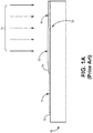
- FIGS. 1A-1C illustrate a result from a conventional full-contact mask used in a spray-type or other line-of-sight coating. These figures generally show one or more of substrate 10, mask 12, coating spray 14, and deposited coating 16.
- full-contact mask 12 is secured, adhesively or otherwise, to the flush outer surface 18 of substrate 10 as it is exposed to coating spray 14. This results in deposited coating 16 partially overlaying edge 20 of mask 12. This is intentional, as nearly all spray and line-of-sight coatings will have some overspray 22, and which causes faired section 24 over the portion of mask 12 distal from deposited coating 16.
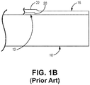
- FIGS. 1B and 1C illustrate an example of what can happen when a full-contact mask is removed after the coating process is complete despite best efforts.
- a full-contact mask 12 is designed to be relatively easily removed from surface 18, it is not always a clean removal.
- a small portion of mask 12 e.g., edge 20
- the stray portion of full-contact mask 12 is left in place, and in others (such as in FIG. 1C ), a worker uses a knife to cut back the mask and overspray area 22, but which leaves a very miniscule lifted or nonadhered portion 28 of coating 16 (exaggerated for clarity).
- deposited coating 16 remains susceptible to further peeling particularly as a result of oncoming fluid flows and pressures such as high-pressure air or combustion gases 30 squarely striking coating face 26 and the space underneath where coating 16 was originally adhered.
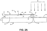
- FIG. 2A and 2B show a first example embodiment of a novel mask arrangement and generally includes substrate 40, standoff mask 42, coating spray 44, and deposited coating 46.
- Mask 42 includes masking body 48 and standoff arrangement 50.
- Masking body has at least first (longitudinal) edge 52, second (longitudinal) edge 54, and third (facing) edge 56, together defining at least part of a perimeter (not numbered) around first surface 58 and second opposing surface 60.
- Standoff arrangement 50 includes at least one projection 64 extending from second surface 60 of masking body 48.
- Projection(s) 64 can be connected to the first or second surface (here, second surface 60) at a location 68 inward from the at least one edge of masking body 42 (here, inward from second edge 54). This defines first overhanging portion 70 of masking body overhanging projection(s) 64 proximate to second edge 54.
- coating 46 can be deposited as normal, with first portion 72A of overspray on second surface 58 of masking body 48 and second portion 72B of overspray on substrate 40. This also naturally results in a faired or feathered coating edge 73. This portion of the coating edge would be removed in a conventional full contact masking arrangement (see in particular FIGS. 1B and 1C ).
- the at least one projection 64 includes resilient layer 74 extending longitudinally between first and second standoff ends 76, 78 thereby the combination defining at least first overhang portion 70.
- both of the first and second standoff ends 76, 78 are offset longitudinally inwardly from the corresponding first and second longitudinal edges 52, 54 of the masking body.
- a second opposing overhang portion (not shown) of masking body 48 can be formed.
- FIG. 3 shows an example packaging configuration for the above example embodiment.
- masking body 48 can be a flexible material and resilient layer 50 includes flexible foam.
- This allows standoff mask 42 to be packaged into roll 80 for easy transport and dispensing for different uses.
- This consumable form of the stand-off makant may be appropriate for large coated areas where a durable mask may be cumbersome or where areas to be masked are highly variable such as for repairs or one-time use appications, particularly ones useful for the roll in FIG. 3 ).
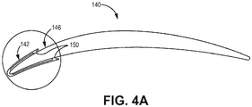
- a second example mask arrangement 142 for selectively applying line-of-sight coating 144 and forming deposited coating 146.
- mask can include standoff portion 150 comprising one or more protrusions 164 with mounting surface 166 for engaging a surface of substrate 140 to be masked.
- the coating has been applied to a recess in the surface such that the resulting coated surface is tangent continuous with the uncoated surface. The small fillet of the recess is filled by the faired edge of the coating provided by diffusion of the spray due to the stand-off maskant.
- protrusions 164 of standoff portion 150 are each offset inward from corresponding first and second edge of masking body 148. In addition to defining inner and outer surfaces, by using protrusions in place of the arrangement in FIGS. 2A and 2B , this defines a recess 167 between the first and second protrusions 164, beneath or inward of masking body 148 when applied to substrate 140.
- mask 142 includes radially outer curved masking body 148 including at least first longitudinal edge 152 and second longitudinal edge 154 together defining a perimeter around first outer surface 158 and second opposing inner surface 160 (in the airfoil example, corresponding to portions of suction and pressure sidewalls immediately behind the leading edge).
- projections or protrusions 164 are connected to the second surface at a location inward from the corresponding first and second longitudinal edges of masking body 142. Like the first example, this defines first and second overhanging portions 170A, 170B proximate to edges 150, 152 of the masking body 142.
- Coating methods according to the disclosure which can take advantage of the above described features are also provided.
- One such example of a method includes positioning a stand-off mask, such as is defined above, over a first portion of a substrate. Once in place, the method also includes applying a line-of-sight coating substantially perpendicular to a second portion of the substrate adjacent to the substrate, the coating adjacent to the overhang such that a full depth section of the coating is formed on the second portion and a faired section of the coating is formed under the overhang portion of the mask.
- one useful example application of this method includes masking a curved portion of a substrate such as an airfoil for a turbine engine.
- the curved portion can include the leading edge and areas immediately aft, such as but not limited to the portions of the suction surface and pressure surface immediately aft of and adjacent to the leading edge.
- the second portion to be coated can be recessed into the substrate so that the first portion and the coated surface form a single substantially continuous aerodynamic surface for oncoming air or other fluid.
- a mask includes a masking body including at least a first edge, a second edge, and a third edge, together defining at least part of a perimeter around a first surface and a second opposing surface.
- a standoff arrangement includes at least one projection extending from the first or second surface of the masking body. The at least one projection is connected to the first or second surface at a location inward from the at least one edge of the masking body, thereby defining a first overhanging portion of the masking body overhanging the at least one projection proximate to the at least one edge of the masking body.
- a mask according to an exemplary embodiment of this disclosure includes a masking body including at least a first edge, a second edge, and a third edge, together defining at least part of a perimeter around a first surface and a second opposing surface; and a standoff arrangement including at least one projection extending from the first or second surface of the masking body, the at least one projection connected to the first or second surface at a location inward from the at least one edge of the masking body, thereby defining a first overhanging portion of the masking body overhanging the at least one projection proximate to the at least one edge of the masking body.
- first edge of the masking body is a first longitudinal edge and a second edge is an opposing second longitudinal edge.
- the at least one projection includes a resilient layer extending longitudinally between first and second standoff ends defining at least the first overhang portion of the masking body.
- both of the first and second standoff ends are offset longitudinally inwardly from the corresponding first or second longitudinal edge of the masking body, defining the first overhang portion and a second opposing overhang portion of the masking body.
- the masking body comprises a flexible material and the resilient layer comprises a flexible foam.
- a further embodiment of any of the foregoing masks wherein the first or second surface of the masking body is adhesively joined to a facing surface of the resilient layer.
- the standoff portion comprises a first protrusion and a mounting surface for engaging a substrate to be masked.
- the standoff portion further comprises a second protrusion offset inward from a second edge of the masking body, defining a recess between the first and second protrusions beneath the masking body when applied to a substrate.
- a mask for an airfoil leading edge includes a radially outer curved masking body and a radially inner standoff arrangement.
- the masking body includes at least a first longitudinal edge and a second opposing longitudinal edge together defining a perimeter around a first outer surface and a second opposing inner surface.
- the standoff arrangement includes at least one projection extending from the second inner surface of the masking body. The at least one projection is connected to the second surface at a location inward from the at least one edge of the masking body, thereby defining a first overhanging portion of the masking body overhanging the at least one projection proximate to the at least one edge of the masking body.
- a mask according to an exemplary embodiment of this disclosure includes a radially outer curved masking body including at least a first longitudinal edge and a second opposing longitudinal edge together defining a perimeter around a first outer surface and a second opposing inner surface; and a standoff arrangement including at least one projection extending from the second inner surface of the masking body, the at least one projection connected to the second surface at a location inward from the at least one edge of the masking body, thereby defining a first overhanging portion of the masking body overhanging the at least one projection proximate to the at least one edge of the masking body.
- the at least one projection includes a resilient layer extending longitudinally between first and second standoff ends defining at least the first overhang portion of the masking body.
- both of the first and second standoff ends are offset longitudinally inwardly from the corresponding first or second longitudinal edge of the masking body, defining the first overhang portion and a second opposing overhang portion of the masking body.
- the masking body comprises a flexible material and the resilient layer comprises a flexible foam.
- a further embodiment of any of the foregoing masks further comprising a first adhesive layer joining the first or second surface of the masking body to a facing surface of the resilient layer, and a second adhesive layer for joining the resilient layer to a substrate to be masked.
- An embodiment of a method includes positioning a mask over a first portion of a substrate and applying a line-of-sight coating substantially perpendicular to a second portion of the substrate adjacent to the first portion.
- the mask includes a masking body with at least one edge including at least a first edge, a second edge, and a third edge, together defining a perimeter around a first surface and a second opposing surface.
- a standoff arrangement on the mask includes at least one projection extending from the first or second surface of the masking body.
- the at least one projection is connected to the first or second surface at a location inward from the at least one edge of the masking body, thereby defining a first overhanging portion of the masking body overhanging the at least one projection proximate to the at least one edge of the masking body.
- the coating is applied adjacent to the overhang so that a full depth section of the coating is formed on the second portion and a faired section of the coating is formed under the overhang.
- a mask according to an exemplary embodiment of this disclosure includespositioning a mask over a first portion of a substrate, the mask comprising: a masking body including at least a first edge, a second edge, and a third edge, together defining at least part of a perimeter around a first surface and a second opposing surface; and a standoff arrangement including at least one projection extending from the first or second surface of the masking body, the at least one projection connected to the first or second surface at a location inward from the at least one edge of the masking body, thereby defining a first overhanging portion of the masking body overhanging the at least one projection proximate to the at least one edge of the masking body; applying a line-of-sight coating substantially perpendicular to a second portion of the substrate adjacent to the first portion, such that the coating is applied adjacent to the overhang
- the substrate comprises an airfoil for a turbine engine.
- the first portion consists of the leading edge and at least one of a suction surface and a pressure surface adjacent to the leading edge.
Landscapes
- Chemical & Material Sciences (AREA)
- Engineering & Computer Science (AREA)
- Physics & Mathematics (AREA)
- Plasma & Fusion (AREA)
- Chemical Kinetics & Catalysis (AREA)
- Materials Engineering (AREA)
- Mechanical Engineering (AREA)
- Metallurgy (AREA)
- Organic Chemistry (AREA)
- Details Or Accessories Of Spraying Plant Or Apparatus (AREA)
Abstract
Description
- The disclosure relates generally to coatings, and more specifically to masking for spray coatings such that peeling is effectively eliminated upon removal of the maskant.
- Traditional masking for airfoil coatings and the like utilize a mask in full and direct contact with the surface to be protected from overspray. This results in at least three related problems. First, when the full-contact mask is removed, even if done so precisely at the edge of the mask, there is no faired section to facilitate smooth fluid flow over the transition between the uncoated and coated sections. Second, removal of the maskant after the application of multiple coats may cause peeling of the coating at its periphery due to the structural cohesiveness developed by the coating and its resistance to separation as the maskant is pulled away from the application surface. Third, when scoring of the coating is performed to alleviate peeling of the coating upon removal of the maskant, any deviation away from the maskant edge may result in maskant being permanently embedded between the resulting coating and substrate which can exacerbate peeling of the coating particularly in the face of direct fluid flow against the facing edge of the coating.
- A mask includes a masking body including at least a first edge, a second edge, and a third edge, together defining at least part of a perimeter around a first surface and a second opposing surface. A standoff arrangement includes at least one projection extending from the first or second surface of the masking body. The at least one projection is connected to the first or second surface at a location inward from the at least one edge of the masking body, thereby defining a first overhanging portion of the masking body overhanging the at least one projection proximate to the at least one edge of the masking body.
- A mask for an airfoil leading edge includes a radially outer curved masking body and a radially inner standoff arrangement. The masking body includes at least a first longitudinal edge and a second opposing longitudinal edge together defining a perimeter around a first outer surface and a second opposing inner surface. The standoff arrangement includes at least one projection extending from the second inner surface of the masking body. The at least one projection is connected to the second surface at a location inward from the at least one edge of the masking body, thereby defining a first overhanging portion of the masking body overhanging the at least one projection proximate to the at least one edge of the masking body.
- An embodiment of a method includes positioning a mask over a first portion of a substrate and applying a line-of-sight coating substantially perpendicular to a second portion of the substrate adjacent to the first portion. The mask includes a masking body with at least one edge including at least a first edge, a second edge, and a third edge, together defining a perimeter around a first surface and a second opposing surface. A standoff arrangement on the mask includes at least one projection extending from the first or second surface of the masking body. The at least one projection is connected to the first or second surface at a location inward from the at least one edge of the masking body, thereby defining a first overhanging portion of the masking body overhanging the at least one projection proximate to the at least one edge of the masking body. The coating is applied adjacent to the overhang so that a full depth section of the coating is formed on the second portion and a faired section of the coating is formed under the overhang.
-
-
FIGS. 1A-1C show a conventional mask and the accompanying issues therewith. -
FIGS. 2A-2B show a first example embodiment of a consumable mask arrangement with standoff, overhang, and adhesive connection to the standoff material to the substrate. -
FIG. 3 shows an example package roll for storing or applying the consumable mask to the arrangement shown inFIGS. 2A-2B . -
FIGS. 4A-4B show a second embodiment of a reusable mask arrangement with standoff and overhang portions relative to the substrate. - By providing an overhang on one or both edges of the mask, by way of a recessed standoff, all three of these issues can be alleviated. With a modified standoff mask, a perpendicular spray will only minimally infiltrate the space under the overhang, allowing for a faired edge to the coating to facilitate smoother fluid flow from the uncoated portion to the coated portion. This also greatly reduces the possibility of peeling even in the face of direct fluid flow against the boundary of the coating as the thickness of the coating decreases to zero at its boundary, and it is no longer necessary to estimate the edge of a full-contact mask and inadvertently create a stepped facing edge and/or leave behind masking material under the coating.
-
FIGS. 1A-1C illustrate a result from a conventional full-contact mask used in a spray-type or other line-of-sight coating. These figures generally show one or more ofsubstrate 10,mask 12,coating spray 14, and depositedcoating 16. InFIG. 1A , full-contact mask 12 is secured, adhesively or otherwise, to the flushouter surface 18 ofsubstrate 10 as it is exposed tocoating spray 14. This results in depositedcoating 16 partially overlayingedge 20 ofmask 12. This is intentional, as nearly all spray and line-of-sight coatings will have someoverspray 22, and which causes fairedsection 24 over the portion ofmask 12 distal from depositedcoating 16. -
FIGS. 1B and1C illustrate an example of what can happen when a full-contact mask is removed after the coating process is complete despite best efforts. Though often a full-contact mask 12 is designed to be relatively easily removed fromsurface 18, it is not always a clean removal. Thus in some cases, a small portion of mask 12 (e.g., edge 20) remains under theoverspray area 22. In some instances, the stray portion of full-contact mask 12 is left in place, and in others (such as inFIG. 1C ), a worker uses a knife to cut back the mask and oversprayarea 22, but which leaves a very miniscule lifted or nonadheredportion 28 of coating 16 (exaggerated for clarity). In both examples, depositedcoating 16 remains susceptible to further peeling particularly as a result of oncoming fluid flows and pressures such as high-pressure air orcombustion gases 30 squarelystriking coating face 26 and the space underneath wherecoating 16 was originally adhered. -
FIG. 2A and2B show a first example embodiment of a novel mask arrangement and generally includessubstrate 40,standoff mask 42,coating spray 44, and depositedcoating 46.Mask 42 includesmasking body 48 andstandoff arrangement 50. Masking body has at least first (longitudinal)edge 52, second (longitudinal)edge 54, and third (facing)edge 56, together defining at least part of a perimeter (not numbered) aroundfirst surface 58 and secondopposing surface 60. -
Standoff arrangement 50 includes at least oneprojection 64 extending fromsecond surface 60 ofmasking body 48. Projection(s) 64 can be connected to the first or second surface (here, second surface 60) at alocation 68 inward from the at least one edge of masking body 42 (here, inward from second edge 54). This defines first overhangingportion 70 of masking body overhanging projection(s) 64 proximate tosecond edge 54. Thus whencoating spray 44 is directed along the coating path,coating 46 can be deposited as normal, withfirst portion 72A of overspray onsecond surface 58 ofmasking body 48 andsecond portion 72B of overspray onsubstrate 40. This also naturally results in a faired orfeathered coating edge 73. This portion of the coating edge would be removed in a conventional full contact masking arrangement (see in particularFIGS. 1B and1C ). - In certain embodiments, the at least one
projection 64 includesresilient layer 74 extending longitudinally between first andsecond standoff ends first overhang portion 70. In certain embodiments, both of the first andsecond standoff ends longitudinal edges first overhang portion 70, a second opposing overhang portion (not shown) ofmasking body 48 can be formed. -
FIG. 3 shows an example packaging configuration for the above example embodiment. Here,masking body 48 can be a flexible material andresilient layer 50 includes flexible foam. This allowsstandoff mask 42 to be packaged intoroll 80 for easy transport and dispensing for different uses. This consumable form of the stand-off makant may be appropriate for large coated areas where a durable mask may be cumbersome or where areas to be masked are highly variable such as for repairs or one-time use appications, particularly ones useful for the roll inFIG. 3 ). - Moving to
FIG. 4A andFIG. 4B , a secondexample mask arrangement 142 for selectively applying line-of-sight coating 144 and forming depositedcoating 146. In addition to masking body 148, mask can includestandoff portion 150 comprising one ormore protrusions 164 with mountingsurface 166 for engaging a surface ofsubstrate 140 to be masked. In certain embodiments, such as the non-limiting example shown herein, the coating has been applied to a recess in the surface such that the resulting coated surface is tangent continuous with the uncoated surface. The small fillet of the recess is filled by the faired edge of the coating provided by diffusion of the spray due to the stand-off maskant. - Here,
protrusions 164 ofstandoff portion 150 are each offset inward from corresponding first and second edge of masking body 148. In addition to defining inner and outer surfaces, by using protrusions in place of the arrangement inFIGS. 2A and2B , this defines arecess 167 between the first andsecond protrusions 164, beneath or inward of masking body 148 when applied tosubstrate 140. - This arrangement is also well-suited for curved substrates where the
curved portion 172 is to be protected from coating applied to aft surfaces, such as the leading edge of an airfoil in a turbine engine. Thus here,mask 142 includes radially outer curved masking body 148 including at least firstlongitudinal edge 152 and secondlongitudinal edge 154 together defining a perimeter around firstouter surface 158 and second opposing inner surface 160 (in the airfoil example, corresponding to portions of suction and pressure sidewalls immediately behind the leading edge). - As noted, projections or
protrusions 164 are connected to the second surface at a location inward from the corresponding first and second longitudinal edges of maskingbody 142. Like the first example, this defines first and second overhangingportions 170A, 170B proximate toedges body 142. - Coating methods according to the disclosure which can take advantage of the above described features are also provided. One such example of a method includes positioning a stand-off mask, such as is defined above, over a first portion of a substrate. Once in place, the method also includes applying a line-of-sight coating substantially perpendicular to a second portion of the substrate adjacent to the substrate, the coating adjacent to the overhang such that a full depth section of the coating is formed on the second portion and a faired section of the coating is formed under the overhang portion of the mask.
- As noted, one useful example application of this method includes masking a curved portion of a substrate such as an airfoil for a turbine engine. The curved portion can include the leading edge and areas immediately aft, such as but not limited to the portions of the suction surface and pressure surface immediately aft of and adjacent to the leading edge. The second portion to be coated can be recessed into the substrate so that the first portion and the coated surface form a single substantially continuous aerodynamic surface for oncoming air or other fluid.
- Though one layer is shown, often a coating process will utilize many passes to apply an even or otherwise desired coating thickness distribution in a particular coating process. This disclosure should not be read to limit any of the claims to a particular number of coating passes in a particular coating process or related coating processes.
- The following are non-exclusive descriptions of possible embodiments of the present disclosure.
- A mask includes a masking body including at least a first edge, a second edge, and a third edge, together defining at least part of a perimeter around a first surface and a second opposing surface. A standoff arrangement includes at least one projection extending from the first or second surface of the masking body. The at least one projection is connected to the first or second surface at a location inward from the at least one edge of the masking body, thereby defining a first overhanging portion of the masking body overhanging the at least one projection proximate to the at least one edge of the masking body.
- The mask of the preceding paragraph can optionally include, additionally and/or alternatively, any one or more of the following features, configurations and/or additional components:
A mask according to an exemplary embodiment of this disclosure, among other possible things includes a masking body including at least a first edge, a second edge, and a third edge, together defining at least part of a perimeter around a first surface and a second opposing surface; and a standoff arrangement including at least one projection extending from the first or second surface of the masking body, the at least one projection connected to the first or second surface at a location inward from the at least one edge of the masking body, thereby defining a first overhanging portion of the masking body overhanging the at least one projection proximate to the at least one edge of the masking body. - A further embodiment of the foregoing mask, wherein the first edge of the masking body is a first longitudinal edge and a second edge is an opposing second longitudinal edge.
- A further embodiment of any of the foregoing masks, wherein the at least one projection includes a resilient layer extending longitudinally between first and second standoff ends defining at least the first overhang portion of the masking body.
- A further embodiment of any of the foregoing masks, wherein both of the first and second standoff ends are offset longitudinally inwardly from the corresponding first or second longitudinal edge of the masking body, defining the first overhang portion and a second opposing overhang portion of the masking body.
- A further embodiment of any of the foregoing masks, wherein the masking body comprises a flexible material and the resilient layer comprises a flexible foam.
- A further embodiment of any of the foregoing masks, wherein the first or second surface of the masking body is adhesively joined to a facing surface of the resilient layer.
- A further embodiment of any of the foregoing masks, wherein the standoff portion comprises a first protrusion and a mounting surface for engaging a substrate to be masked.
- A further embodiment of any of the foregoing masks, wherein the standoff portion further comprises a second protrusion offset inward from a second edge of the masking body, defining a recess between the first and second protrusions beneath the masking body when applied to a substrate.
- A mask for an airfoil leading edge includes a radially outer curved masking body and a radially inner standoff arrangement. The masking body includes at least a first longitudinal edge and a second opposing longitudinal edge together defining a perimeter around a first outer surface and a second opposing inner surface. The standoff arrangement includes at least one projection extending from the second inner surface of the masking body. The at least one projection is connected to the second surface at a location inward from the at least one edge of the masking body, thereby defining a first overhanging portion of the masking body overhanging the at least one projection proximate to the at least one edge of the masking body.
- The mask of the preceding paragraph can optionally include, additionally and/or alternatively, any one or more of the following features, configurations and/or additional components:
A mask according to an exemplary embodiment of this disclosure, among other possible things includes a radially outer curved masking body including at least a first longitudinal edge and a second opposing longitudinal edge together defining a perimeter around a first outer surface and a second opposing inner surface; and a standoff arrangement including at least one projection extending from the second inner surface of the masking body, the at least one projection connected to the second surface at a location inward from the at least one edge of the masking body, thereby defining a first overhanging portion of the masking body overhanging the at least one projection proximate to the at least one edge of the masking body. - A further embodiment of the foregoing mask, wherein the at least one projection includes a resilient layer extending longitudinally between first and second standoff ends defining at least the first overhang portion of the masking body.
- A further embodiment of any of the foregoing masks, wherein both of the first and second standoff ends are offset longitudinally inwardly from the corresponding first or second longitudinal edge of the masking body, defining the first overhang portion and a second opposing overhang portion of the masking body.
- A further embodiment of any of the foregoing masks, wherein the masking body comprises a flexible material and the resilient layer comprises a flexible foam.
- A further embodiment of any of the foregoing masks, further comprising a first adhesive layer joining the first or second surface of the masking body to a facing surface of the resilient layer, and a second adhesive layer for joining the resilient layer to a substrate to be masked.
- A further embodiment of any of the foregoing masks, wherein the inner standoff portion comprises a first protrusion at the first end.
- A further embodiment of any of the foregoing masks, wherein the inner standoff portion comprises a second protrusion at the second end.
- An embodiment of a method includes positioning a mask over a first portion of a substrate and applying a line-of-sight coating substantially perpendicular to a second portion of the substrate adjacent to the first portion. The mask includes a masking body with at least one edge including at least a first edge, a second edge, and a third edge, together defining a perimeter around a first surface and a second opposing surface. A standoff arrangement on the mask includes at least one projection extending from the first or second surface of the masking body. The at least one projection is connected to the first or second surface at a location inward from the at least one edge of the masking body, thereby defining a first overhanging portion of the masking body overhanging the at least one projection proximate to the at least one edge of the masking body. The coating is applied adjacent to the overhang so that a full depth section of the coating is formed on the second portion and a faired section of the coating is formed under the overhang.
- The mask of the preceding paragraph can optionally include, additionally and/or alternatively, any one or more of the following features, configurations and/or additional components:
A mask according to an exemplary embodiment of this disclosure, among other possible things includespositioning a mask over a first portion of a substrate, the mask comprising: a masking body including at least a first edge, a second edge, and a third edge, together defining at least part of a perimeter around a first surface and a second opposing surface; and a standoff arrangement including at least one projection extending from the first or second surface of the masking body, the at least one projection connected to the first or second surface at a location inward from the at least one edge of the masking body, thereby defining a first overhanging portion of the masking body overhanging the at least one projection proximate to the at least one edge of the masking body; applying a line-of-sight coating substantially perpendicular to a second portion of the substrate adjacent to the first portion, such that the coating is applied adjacent to the overhang so that a full depth section of the coating is formed on the second portion and a faired section of the coating is formed under the overhang. - A further embodiment of the foregoing method, wherein the substrate comprises an airfoil for a turbine engine.
- A further embodiment of any of the foregoing methods, wherein the first portion consists of the leading edge and at least one of a suction surface and a pressure surface adjacent to the leading edge.
- A further embodiment of any of the foregoing methods, wherein the second portion is recessed into the substrate so that the first portion and the coated surface form a single substantially continuous aerodynamic surface for oncoming air/fluid.
- While the invention has been described with reference to an exemplary embodiment(s), it will be understood by those skilled in the art that various changes may be made and equivalents may be substituted for elements thereof without departing from the scope of the invention. In addition, many modifications may be made to adapt a particular situation or material to the teachings of the invention without departing from the essential scope thereof. Therefore, it is intended that the invention not be limited to the particular embodiment(s) disclosed, but that the invention will include all embodiments falling within the scope of the appended claims.
Claims (15)
- A mask (42;142) comprising:a masking body (48;148) including at least a first edge (52;152), a second edge (54;154), and a third edge (56), together defining at least part of a perimeter around a first surface (58;158) and a second opposing surface (60;160); anda standoff arrangement (50;150) including at least one projection (64;164) extending from the first or second surface (58,60;158,160) of the masking body (48;148), the at least one projection (64;164) connected to the first or second surface (58,60;158,160) at a location inward from the at least one edge (52,54,56;152,154) of the masking body (48;148), thereby defining a first overhanging portion (70;170) of the masking body (48;148) overhanging the at least one projection (64;164) proximate to the at least one edge (52,54,56;152,154) of the masking body (48;148).
- The mask of claim 1, wherein the first edge (52;152) of the masking body (48;148) is a first longitudinal edge (52;152) and a second edge (54;154) is an opposing second longitudinal edge (54;154).
- A mask (142) for an airfoil leading edge, the mask (142) comprising:a radially outer curved masking body (148) including at least a first longitudinal edge (152) and a second opposing longitudinal edge (154) together defining a perimeter around a first outer surface (158) and a second opposing inner surface (160); anda standoff arrangement (150) including at least one projection (164) extending from the second inner surface (160) of the masking body (148), the at least one projection (164) connected to the second surface (160) at a location inward from the at least one edge (152,154) of the masking body (148), thereby defining a first overhanging portion (170) of the masking body (148) overhanging the at least one projection (164) proximate to the at least one edge (152,154) of the masking body (148).
- The mask of claim 3, wherein the inner standoff portion comprises a first protrusion (164) at a first end.
- The mask of claim 4, wherein the inner standoff portion comprises a second protrusion (164) at a second end.
- The mask of any preceding claim, wherein the at least one projection (64;164) includes a resilient layer (74) extending longitudinally between first and second standoff ends (76,78) defining at least the first overhang portion (70) of the masking body (48;148).
- The mask of claim 6, wherein both of the first and second standoff ends (76,78) are offset longitudinally inwardly from the corresponding first or second longitudinal edge (52,54;152,154) of the masking body (48;148), defining the first overhang portion (70;170) and a second opposing overhang portion of the masking body (48;148).
- The mask arrangement of claim 6 or 7, wherein the masking body (48;148) comprises a flexible material and the resilient layer (74) comprises a flexible foam.
- The mask of claim 6, 7 or 8, wherein the first or second surface (58,60;158,160) of the masking body (48;148) is adhesively joined to a facing surface of the resilient layer (74).
- The mask of claim 9, further comprising an adhesive layer for joining the resilient layer (74) to a substrate (40;140) to be masked.
- The mask of any preceding claim, wherein the standoff arrangement (50;150) comprises a/the first protrusion (64;164) and a mounting surface (166) for engaging a substrate (40;140) to be masked.
- The mask of claim 11, wherein the standoff arrangement (50;150) further comprises a/the second protrusion (64;164) offset inward from the second edge (54;154) of the masking body (48;148), defining a recess (167) between the first and second protrusions (64;164) beneath the masking body (48;148) when applied to a substrate (40;140).
- A method comprising:positioning the mask (42;142) of any preceding claim over a first portion of a substrate (40;140);applying a line-of-sight coating (46;146) substantially perpendicular to a second portion of the substrate (40;140) adjacent to the first portion, such that the coating (46;146) is applied adjacent to the overhang (70;170) so that a full depth section of the coating (46;146) is formed on the second portion and a faired section (73) of the coating (46;146) is formed under the overhang (70; 170).
- The method of claim 13, wherein the substrate (40;140) comprises an airfoil for a turbine engine.
- The method of claim 14, wherein the first portion consists of the leading edge and at least one of a suction surface and a pressure surface adjacent to the leading edge; and
wherein, optionally, the second portion is recessed into the substrate (40;140) so that the first portion and the coated surface (46; 146) form a single substantially continuous aerodynamic surface for oncoming air/fluid.
Applications Claiming Priority (1)
| Application Number | Priority Date | Filing Date | Title |
|---|---|---|---|
| US16/027,823 US11154901B2 (en) | 2018-07-05 | 2018-07-05 | Offset masking device and method |
Publications (1)
| Publication Number | Publication Date |
|---|---|
| EP3590606A1 true EP3590606A1 (en) | 2020-01-08 |
Family
ID=67180564
Family Applications (1)
| Application Number | Title | Priority Date | Filing Date |
|---|---|---|---|
| EP19184256.6A Withdrawn EP3590606A1 (en) | 2018-07-05 | 2019-07-03 | Offset masking device and method |
Country Status (2)
| Country | Link |
|---|---|
| US (1) | US11154901B2 (en) |
| EP (1) | EP3590606A1 (en) |
Families Citing this family (3)
| Publication number | Priority date | Publication date | Assignee | Title |
|---|---|---|---|---|
| CN109778116B (en) * | 2019-03-28 | 2021-03-02 | 京东方科技集团股份有限公司 | A kind of mask plate and its production method, mask plate assembly |
| EP4151383B1 (en) * | 2021-09-21 | 2026-02-11 | LM Wind Power A/S | Method of masking a mould for moulding a wind turbine blade shell part |
| WO2025128571A1 (en) * | 2023-12-11 | 2025-06-19 | Integrated Global Services, Inc. | Rigid masking devices and methods for in-situ application of a spray-applied coating material onto a substrate surface |
Citations (6)
| Publication number | Priority date | Publication date | Assignee | Title |
|---|---|---|---|---|
| US5407716A (en) * | 1991-04-19 | 1995-04-18 | Minnesota Mining And Manufacturing Company | Masking methods using flexible strip |
| WO2002068556A2 (en) * | 2001-02-24 | 2002-09-06 | Jevtec Limited | Foam masking tape |
| EP1760168A2 (en) * | 2005-09-01 | 2007-03-07 | United Technologies Corporation | Method for appling a Hybrid thermal barrier coating, and coating articles |
| US20090104356A1 (en) * | 2005-01-04 | 2009-04-23 | Toppen Harvey R | Method of coating and a shield for a component |
| WO2015063525A1 (en) * | 2013-11-04 | 2015-05-07 | Jtape Limited | Masking tape |
| US20150151321A1 (en) * | 2013-11-29 | 2015-06-04 | Siemens Aktiengesellschaft | Method for producing a bevel, component having a bevel and apparatus |
Family Cites Families (2)
| Publication number | Priority date | Publication date | Assignee | Title |
|---|---|---|---|---|
| SG11201500286RA (en) | 2012-07-31 | 2015-02-27 | United Technologies Corp | Coating system and process |
| US20150118444A1 (en) | 2013-10-31 | 2015-04-30 | General Electric Company | Methods of manufacturing silica-forming articles having engineered surfaces to enhance resistance to creep sliding under high-temperature loading |
-
2018
- 2018-07-05 US US16/027,823 patent/US11154901B2/en active Active
-
2019
- 2019-07-03 EP EP19184256.6A patent/EP3590606A1/en not_active Withdrawn
Patent Citations (6)
| Publication number | Priority date | Publication date | Assignee | Title |
|---|---|---|---|---|
| US5407716A (en) * | 1991-04-19 | 1995-04-18 | Minnesota Mining And Manufacturing Company | Masking methods using flexible strip |
| WO2002068556A2 (en) * | 2001-02-24 | 2002-09-06 | Jevtec Limited | Foam masking tape |
| US20090104356A1 (en) * | 2005-01-04 | 2009-04-23 | Toppen Harvey R | Method of coating and a shield for a component |
| EP1760168A2 (en) * | 2005-09-01 | 2007-03-07 | United Technologies Corporation | Method for appling a Hybrid thermal barrier coating, and coating articles |
| WO2015063525A1 (en) * | 2013-11-04 | 2015-05-07 | Jtape Limited | Masking tape |
| US20150151321A1 (en) * | 2013-11-29 | 2015-06-04 | Siemens Aktiengesellschaft | Method for producing a bevel, component having a bevel and apparatus |
Also Published As
| Publication number | Publication date |
|---|---|
| US11154901B2 (en) | 2021-10-26 |
| US20200009609A1 (en) | 2020-01-09 |
Similar Documents
| Publication | Publication Date | Title |
|---|---|---|
| EP3590606A1 (en) | Offset masking device and method | |
| FI118638B (en) | Adhesive tape, joint and method of making the joint | |
| US9757755B2 (en) | Masking strip | |
| WO2013137964A3 (en) | Method and coating for protecting and repairing an airfoil surface | |
| SG139615A1 (en) | Pre-coating burnishing of erosion coated parts | |
| US20220246065A1 (en) | Linerless combined mailing label and return label and method of manufacturing same | |
| KR20090126206A (en) | Adhesive Tapes and Their Uses | |
| US8173218B2 (en) | Method of spraying a turbine engine component | |
| US8211506B2 (en) | Coating methods and apparatus using pre-formed ceramic mask | |
| RU2583200C2 (en) | Detachable mask for blade platform or sector distributor of turbo-machine | |
| US20110281079A1 (en) | Double-Faced tape | |
| US5939173A (en) | Cellular material strip | |
| CN111108311B (en) | Sealing strip for processing as continuous strip | |
| CN207222193U (en) | Supporting member for automotive component japanning | |
| US9868133B1 (en) | Masking device | |
| US20200198256A1 (en) | Intermediary Protective Bonding Layer Onto Which an Additional Part(s) is to be Adhered for Both Cosmetic Appeal and Ease of Undamaged Removal | |
| CN223134378U (en) | Shielding film components | |
| CN222606762U (en) | A protective sticker for paint spraying | |
| JPH055547B2 (en) | ||
| KR100809137B1 (en) | Joining method for flying joining of flat web material wound with a cover strip and roll to at least partially cover the adhesive tape for flying joining | |
| JPH1177859A (en) | Bonding method for paper saw blade | |
| JP2016137436A (en) | Painting method | |
| CA2848081A1 (en) | Peel-resistant mechanism for use in bonding components | |
| JP6661503B2 (en) | Plate material bending method | |
| JP2014104449A (en) | Masking tape for bridge and bridge masking method |
Legal Events
| Date | Code | Title | Description |
|---|---|---|---|
| PUAI | Public reference made under article 153(3) epc to a published international application that has entered the european phase |
Free format text: ORIGINAL CODE: 0009012 |
|
| STAA | Information on the status of an ep patent application or granted ep patent |
Free format text: STATUS: THE APPLICATION HAS BEEN PUBLISHED |
|
| AK | Designated contracting states |
Kind code of ref document: A1 Designated state(s): AL AT BE BG CH CY CZ DE DK EE ES FI FR GB GR HR HU IE IS IT LI LT LU LV MC MK MT NL NO PL PT RO RS SE SI SK SM TR |
|
| AX | Request for extension of the european patent |
Extension state: BA ME |
|
| STAA | Information on the status of an ep patent application or granted ep patent |
Free format text: STATUS: REQUEST FOR EXAMINATION WAS MADE |
|
| 17P | Request for examination filed |
Effective date: 20200708 |
|
| RBV | Designated contracting states (corrected) |
Designated state(s): AL AT BE BG CH CY CZ DE DK EE ES FI FR GB GR HR HU IE IS IT LI LT LU LV MC MK MT NL NO PL PT RO RS SE SI SK SM TR |
|
| STAA | Information on the status of an ep patent application or granted ep patent |
Free format text: STATUS: THE APPLICATION IS DEEMED TO BE WITHDRAWN |
|
| 18D | Application deemed to be withdrawn |
Effective date: 20200709 |