EP3590575A1 - Electrode with movable insertion stopper - Google Patents
Electrode with movable insertion stopper Download PDFInfo
- Publication number
- EP3590575A1 EP3590575A1 EP19192549.4A EP19192549A EP3590575A1 EP 3590575 A1 EP3590575 A1 EP 3590575A1 EP 19192549 A EP19192549 A EP 19192549A EP 3590575 A1 EP3590575 A1 EP 3590575A1
- Authority
- EP
- European Patent Office
- Prior art keywords
- stopper
- electrode
- carrier
- electrode carrier
- clip
- Prior art date
- Legal status (The legal status is an assumption and is not a legal conclusion. Google has not performed a legal analysis and makes no representation as to the accuracy of the status listed.)
- Granted
Links
Images







Classifications
-
- A—HUMAN NECESSITIES
- A61—MEDICAL OR VETERINARY SCIENCE; HYGIENE
- A61N—ELECTROTHERAPY; MAGNETOTHERAPY; RADIATION THERAPY; ULTRASOUND THERAPY
- A61N1/00—Electrotherapy; Circuits therefor
- A61N1/02—Details
- A61N1/04—Electrodes
- A61N1/05—Electrodes for implantation or insertion into the body, e.g. heart electrode
- A61N1/0526—Head electrodes
- A61N1/0541—Cochlear electrodes
-
- A—HUMAN NECESSITIES
- A61—MEDICAL OR VETERINARY SCIENCE; HYGIENE
- A61M—DEVICES FOR INTRODUCING MEDIA INTO, OR ONTO, THE BODY; DEVICES FOR TRANSDUCING BODY MEDIA OR FOR TAKING MEDIA FROM THE BODY; DEVICES FOR PRODUCING OR ENDING SLEEP OR STUPOR
- A61M31/00—Devices for introducing or retaining media, e.g. remedies, in cavities of the body
- A61M31/002—Devices for releasing a drug at a continuous and controlled rate for a prolonged period of time
-
- A—HUMAN NECESSITIES
- A61—MEDICAL OR VETERINARY SCIENCE; HYGIENE
- A61B—DIAGNOSIS; SURGERY; IDENTIFICATION
- A61B90/00—Instruments, implements or accessories specially adapted for surgery or diagnosis and not covered by any of the groups A61B1/00 - A61B50/00, e.g. for luxation treatment or for protecting wound edges
- A61B90/03—Automatic limiting or abutting means, e.g. for safety
- A61B2090/033—Abutting means, stops, e.g. abutting on tissue or skin
- A61B2090/034—Abutting means, stops, e.g. abutting on tissue or skin abutting on parts of the device itself
-
- A—HUMAN NECESSITIES
- A61—MEDICAL OR VETERINARY SCIENCE; HYGIENE
- A61B—DIAGNOSIS; SURGERY; IDENTIFICATION
- A61B90/00—Instruments, implements or accessories specially adapted for surgery or diagnosis and not covered by any of the groups A61B1/00 - A61B50/00, e.g. for luxation treatment or for protecting wound edges
- A61B90/03—Automatic limiting or abutting means, e.g. for safety
- A61B2090/033—Abutting means, stops, e.g. abutting on tissue or skin
- A61B2090/036—Abutting means, stops, e.g. abutting on tissue or skin abutting on tissue or skin
-
- F—MECHANICAL ENGINEERING; LIGHTING; HEATING; WEAPONS; BLASTING
- F04—POSITIVE - DISPLACEMENT MACHINES FOR LIQUIDS; PUMPS FOR LIQUIDS OR ELASTIC FLUIDS
- F04C—ROTARY-PISTON, OR OSCILLATING-PISTON, POSITIVE-DISPLACEMENT MACHINES FOR LIQUIDS; ROTARY-PISTON, OR OSCILLATING-PISTON, POSITIVE-DISPLACEMENT PUMPS
- F04C2270/00—Control; Monitoring or safety arrangements
- F04C2270/04—Force
- F04C2270/042—Force radial
- F04C2270/0421—Controlled or regulated
Definitions
- the present invention generally relates to electrodes for medical implants and, more particularly, the invention relates to an electrode carrier with a movable insertion stopper that aids in the insertion process.
- cochlear implants can restore some sense of hearing by direct electrical stimulation of the neural tissue of the cochlea.
- the cochlear implant typically includes an electrode carrier having an electrode lead and an electrode array, which is threaded into the cochlea.
- the electrode array usually includes multiple electrodes on its surface that electrically stimulate auditory nerve tissue with small currents delivered by the electrodes distributed along the electrode array. These electrodes are typically located toward the end of the electrode carrier and are in electrical communication with an electronics module that produces an electrical stimulation signal for the implanted electrodes to stimulate the cochlea.
- cochlear duct length i.e., the length measured from the round window entrance until the most apex of the cochlea (helicotrema)
- the cochlear duct length typically varies from about 25 mm to 35 mm.
- manufacturers of cochlear implants provide a wide range of electrode array lengths so as to cover the diversified cochlear duct length in patients.
- Some cochlear electrodes include a fixed insertion stopper to indicate the maximum insertion depth for the electrode array. The insertion stopper may also serve as a cap to close the round window opening, or cochleostomy site, where the electrode array is inserted into the cochlea.
- the electrode array is not inserted into the scala tympani beyond a certain insertion depth and stops well before the fixed insertion stopper reaches the cochleostomy due to a variety of situations, e.g., the electrode array length is too long for that particular cochlea, greater anatomical resistance inside the cochlea, insufficient experience with the surgeon, etc. In such situations, the closing of the round window opening or cochleostomy by the fixed insertion stopper is not possible and the exact electrode array entry point into the scala tympani cannot be determined or identified in radiographs that are taken after implantation.
- a cochlear implant electrode includes an electrode carrier having an electrode array with a groove disposed in a longitudinal direction along the electrode carrier, and a stopper positioned around the electrode carrier.
- the stopper has a protrusion on its inner surface that is configured to be positioned within the groove such that the stopper is movable with respect to the electrode carrier.
- a cochlear implant electrode includes an electrode carrier having an electrode array with grooves, each groove disposed in a transverse direction along the electrode carrier, and a stopper positioned around the electrode carrier.
- the stopper is configured to be positioned within each groove and movable with respect to the electrode carrier.
- a cochlear implant electrode in accordance with another embodiment of the invention, includes an electrode carrier having an electrode array with notches disposed longitudinally along the electrode carrier and a stopper positioned over the electrode carrier.
- the stopper has a locking pin on an inner surface of its proximal end that is configured to be positioned within each notch and that is movable with respect to the electrode carrier.
- the stopper further including a flexible region configured to allow the stopper to expand or contract in length when the locking pin is moved with respect to the electrode carrier.
- the electrode array may include at least one locking groove disposed in a transverse direction such that the stopper is movable within the groove and within the locking groove.
- the stopper may further include a skirt around an outer surface of the stopper that is configured to cover at least a portion of a cochleostomy site.
- the stopper may further include a band disposed inside the stopper that is made of a material that is detectable to radiography, such as a metal.
- the stopper may include an outer surface having two beveled surfaces with one beveled surface being smaller in diameter than the other beveled surface.
- the stopper may include an outer surface having the shape of two cone-shaped cylinders.
- the electrode may further include a clip secured to a position along the electrode array so that the stopper is prevented from moving beyond the position toward the distal end of the electrode carrier.
- the electrode array may further include at least one hole disposed in a transverse direction along the electrode carrier and the electrode may further include a pin configured to fit within the hole so that the stopper is prevented from moving beyond the pin toward the distal end of the electrode carrier.
- the inner surface of the stopper may be substantially similar in shape as an outer surface of the electrode carrier.
- the inner surface of the stopper may be substantially round or circular in shape when fitting over an electrode carrier having a round or circular cross-section. Both the inner surface of the stopper and the outer surface of the electrode carrier may include a flat portion.
- the groove may be disposed on the flat portion of the electrode carrier and the protrusion may be disposed on the flat portion of the stopper.
- the stopper may include a drug that is released from the stopper in order to prevent bacterial infection or fibrous tissue formation at the round window opening or the cochleostomy.
- the stopper is fixed to the electrode carrier at a distal end of the stopper.
- the stopper may further include a clip in its proximal end that is configured to open the stopper such that the locking pin disengages with the notch.
- a cochlear implant electrode that includes a movable insertion stopper positioned around the electrode carrier.
- the stopper may have a protrusion or locking pin on its inner surface that is positioned within, and is movable along, a longitudinal groove on the electrode carrier.
- the electrode carrier may have a series of grooves positioned in a transverse direction and a stopper that may be positioned within each groove and movable between the various grooves.
- the electrode carrier may have a series of notches or holes positioned along the carrier and a stopper that may have a locking pin on its inner surface that is positioned within each notch and movable between the various notches.
- a movable insertion stopper may be moved to any point along the electrode carrier and fixed in a position close to the cochleostomy once the electrode array is inserted into the cochlea, regardless of the insertion depth of the electrode array.
- a movable insertion stopper that can be positioned close to the cochleostomy also provides a more accurate radio marker in post-implantation radiographs.
- a movable insertion stopper that can be positioned close to the cochleostomy and that covers and protects the electrode lead further reduces bacterial infection. Details of illustrative embodiments are discussed below.
- FIG. 1 schematically shows the anatomy of a normal human ear and some components of a typical cochlear implant system.
- the cochlear implant system includes an external microphone (not shown) that provides an audio signal input to an external signal processor 102 where various signal processing schemes may be implemented.
- the processed signal is then converted into a stimulation pattern by an external transmitter/stimulator 104, and the stimulation pattern/signal is transmitted through connected wires (not shown) to an implanted electrode carrier 106.
- the electrode carrier 106 has an electrode lead 108 and an electrode array 110 that is inserted into the cochlea 114 through an opening in the round window or the cochleostomy site 116.
- the electrode array 110 has multiple electrodes 112 on its surface that provide selective stimulation to the cochlea 114.
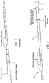
- FIG. 2 schematically shows an electrode carrier with a fixed insertion stopper located between the electrode lead and the electrode array according to the prior art.
- a fixed insertion stopper may not work as intended in situations where the electrode array is not fully inserted into the cochlea and stops well before the fixed insertion stopper reaches the cochleostomy.
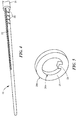
- FIG. 3 schematically shows an electrode 10 according to embodiments of the present invention.
- the electrode 10 includes an electrode carrier 12 having an electrode lead 14 at its distal end and an electrode array 16, with stimulating electrodes 18 distributed along the array, at its proximal end.
- the electrode 10 also includes a movable insertion stopper 20 positioned around the electrode array 16 that is able to slide over the electrode array 16 without too much resistance.
- the insertion stopper 20 may be inserted over or completely removed from the electrode array 16.
- the insertion stopper 20 may be secured at any predefined position along the electrode array 16, as will be discussed in more detail below.
- the electrode lead 14 may serve as a fixed insertion stopper for the electrode, preventing the movable insertion stopper 20 from moving beyond the proximal end of the electrode lead 14 so that the electrode array 16 is not inserted too deeply into the cochlea of a patient.
- the insertion stopper 20 may be made of any biocompatible material such as biocompatible polymer, e.g., silicone which provides better flexibility or PTFE (Teflon) which provides better lubricity during moving and fixing of the insertion stopper along the electrode array 16.
- the electrode carrier 12 includes a groove 22 disposed in a longitudinal direction along the distal end of the electrode array 16.
- the insertion stopper 20 includes a protrusion or pin 24 on its inner surface 20a that is positioned within the groove 22 so that the insertion stopper 20 is movable with respect to the electrode carrier 12.
- the electrode carrier 12 may also include one or more locking grooves 26 disposed in a transverse direction on the electrode carrier 12. The insertion stopper 20 may be secured or locked at any predefined position on the electrode array 16 by rotating the insertion stopper 20 so that the protrusion 24 moves from the longitudinal groove 22 to the locking groove 26.
- the insertion stopper 20 has been shown with an outer surface 20b that is round or circular in shape, other configurations may also be used.
- the insertion stopper 20 may include an outer surface having one or more bulges or beveled surfaces 28, such as shown in FIGS. 7A, 7B and 8 . If the configuration includes two beveled surfaces, then the diameter of the one beveled surface is preferably smaller than the diameter of the other surface, with the smaller beveled surface closer to the proximal end of the electrode array 16.
- the insertion stopper 20 may have an outer surface shaped like one or more cone-shaped cylinders 30, with the smaller diameter portion of the cylinder closer to the proximal end of the electrode array 16.
- This type of configuration allows the smaller beveled surface or the smaller diameter cylinder to be at the front of the movable stopper 20 so that it can enter the round window opening or cochleostomy, which permits the electrode carrier 12 to be more readily affixed to the cochlea, so that any later movements of the electrode carrier 12 after implantation can be minimized or prevented.
- FIGS. 10A and 10B schematically show an electrode carrier 12 and an insertion stopper 20 having at least one flat portion.
- the longitudinal groove 22 may be disposed on a flat portion 12a of the electrode carrier 12 and the protrusion 24 may be positioned on a flat portion 20c of the insertion stopper 20.
- the locking of the insertion stopper 20 may be accomplished in a number of ways rather than using the locking grooves 26.
- a clip 32 may be used that is secured to a position along the electrode array 16, which prevents the insertion stopper 20 from moving beyond that position toward a distal end of the electrode carrier 12.
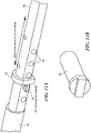
- the electrode carrier 12 may have one or more holes 34 located in the transverse direction along the electrode array 16 and a locking pin 36 that fits within the hole 34, as shown in FIGS. 11A and 11B . This type of configuration also prevents the insertion stopper 20 from moving beyond the pin 36 toward the electrode lead 14 in the distal end of the electrode carrier 12.
- the clip 32 and the locking pin 36 may be made of any biocompatible material such as biocompatible metal or any mechanically stable biocompatible polymer.
- the electrode carrier 12 may include one or more grooves 38 disposed in the transverse direction along the electrode array 16 and an insertion stopper 40 that fits within the grooves 38, such as shown in FIGS. 12A through 12C .
- the insertion stopper 40 does not have the protrusion 24 on its inner surface as previously shown and discussed in connection with insertion stopper 20.
- the transverse grooves 38 are located at predefined positions and the insertion stopper 40 may be moved parallel to the longitudinal axis of the electrode array 16 and positioned within any one of the grooves 38.
- the insertion stopper 40 and the electrode carrier 12 may be made of a biocompatible material, such as a silicone elastomer, which allows the insertion stopper 40 to be easily slid over the electrode carrier 12.
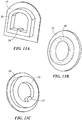
- FIGS. 13A - 13C show an insertion stopper 20, 40 having a skirt 42 around its circumference.
- the skirt 42 allows the electrode carrier 12 to be affixed to nearby tissue when the device is implanted and also may serve as a cap to help close the opening in the round window or cochleostomy.
- FIG. 14A shows an electrode carrier 12 assembled with an insertion stopper 20 having a skirt 42 and
- FIG. 14B schematically shows the electrode array 16 implanted within the cochlear 114 with the insertion stopper 20 provided near the cochleostomy 116.
- the insertion stopper 20, 40 may be secured to the cochlea or the nearby tissue by any biocompatible tissue glue, for example, fibrin glue, biocompatible quick polymer glue, etc.
- the skirt 42 may be made of the same material as that of the insertion stopper 20, 40.
- the insertion stopper 20, 40 may be embedded or loaded with any drug molecules so that the drug is released from the insertion stopper 20, 40 in order to prevent bacterial infection or fibrous tissue formation at the round window opening or the cochleostomy.
- the insertion stopper 20, 40 may have a band 44 that is embedded within the insertion stopper 20, 40.
- the band 44 may be made of any biocompatible material that is detectable in radiographs.
- the band 44 serves as a radio marker to more accurately determine the location of the electrode carrier 12 and cochleostomy in post-implantation radiographs.
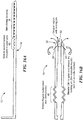
- FIGS. 16A - 16D show an electrode carrier 12 and movable insertion stopper 20 configuration that covers and protects the electrode lead which reduces bacterial infection.
- the electrode carrier 12 includes notches 46 and the movable insertion stopper 20 has a flexible region 48 that is configured to extend or contract depending on the relative position of the stopper 20 in relation to the carrier 12.
- the movable insertion stopper 20 is configured to fit over the electrode lead 14 and includes a locking pin 50 on its inner surface that is configured to engage with and be positioned within the notches 46 on the electrode carrier 12.
- the insertion stopper 20 may include a conical stopper region 52 at its proximal end and may be securely fixed to the electrode carrier 12 at the distal end of the stopper 20, e.g., using silicone or other suitable fixing means. As shown in FIGS. 16C and 16D , the flexible region 48 allows the insertion stopper 20 to expand or contract in length in order to accommodate the locking pin 50 in the various notch 46 positions.
- the insertion stopper 20 may include a clip 54, e.g., a metallic clip, in its proximal end that is configured to open the stopper region 52 such that the locking pin 50 disengages with the notch 46.
- the clip 54 may be detectable in radiographs and serve as a radio marker, similar to the band 44 previously described.
- the clip 54 may be fixed to the nearby bone, tissue, or round window niche to prevent electrode spring back.
- the insertion stopper 20 in this embodiment may further include a skirt 42, such as shown and described with regard to FIGS. 13A- 13C .
Landscapes
- Health & Medical Sciences (AREA)
- Engineering & Computer Science (AREA)
- General Health & Medical Sciences (AREA)
- Animal Behavior & Ethology (AREA)
- Veterinary Medicine (AREA)
- Biomedical Technology (AREA)
- Public Health (AREA)
- Heart & Thoracic Surgery (AREA)
- Life Sciences & Earth Sciences (AREA)
- Radiology & Medical Imaging (AREA)
- Otolaryngology (AREA)
- Nuclear Medicine, Radiotherapy & Molecular Imaging (AREA)
- Cardiology (AREA)
- Chemical & Material Sciences (AREA)
- Bioinformatics & Cheminformatics (AREA)
- Medicinal Chemistry (AREA)
- Anesthesiology (AREA)
- Hematology (AREA)
- Electrotherapy Devices (AREA)
- Prostheses (AREA)
Abstract
Description
- This patent application claims priority to
U.S. Provisional Patent Application No. 61/657,270 filed June 8, 2012 - The present invention generally relates to electrodes for medical implants and, more particularly, the invention relates to an electrode carrier with a movable insertion stopper that aids in the insertion process.
- For many patients with severe to profound hearing impairment, there are several types of middle and inner ear implants that can restore a sense of partial or full hearing. For example, cochlear implants can restore some sense of hearing by direct electrical stimulation of the neural tissue of the cochlea. The cochlear implant typically includes an electrode carrier having an electrode lead and an electrode array, which is threaded into the cochlea. The electrode array usually includes multiple electrodes on its surface that electrically stimulate auditory nerve tissue with small currents delivered by the electrodes distributed along the electrode array. These electrodes are typically located toward the end of the electrode carrier and are in electrical communication with an electronics module that produces an electrical stimulation signal for the implanted electrodes to stimulate the cochlea.
- One of the important steps in cochlear implant surgery is the insertion of the electrode array into the scala tympani of the cochlea. However, the cochlear duct length, i.e., the length measured from the round window entrance until the most apex of the cochlea (helicotrema), varies from patient to patient so no single electrode array length will be suitable for all patients. Literature shows that the cochlear duct length typically varies from about 25 mm to 35 mm. Thus, manufacturers of cochlear implants provide a wide range of electrode array lengths so as to cover the diversified cochlear duct length in patients. Some cochlear electrodes include a fixed insertion stopper to indicate the maximum insertion depth for the electrode array. The insertion stopper may also serve as a cap to close the round window opening, or cochleostomy site, where the electrode array is inserted into the cochlea.
- In some cases, however, during the electrode insertion process, the electrode array is not inserted into the scala tympani beyond a certain insertion depth and stops well before the fixed insertion stopper reaches the cochleostomy due to a variety of situations, e.g., the electrode array length is too long for that particular cochlea, greater anatomical resistance inside the cochlea, insufficient experience with the surgeon, etc. In such situations, the closing of the round window opening or cochleostomy by the fixed insertion stopper is not possible and the exact electrode array entry point into the scala tympani cannot be determined or identified in radiographs that are taken after implantation.
- In accordance with one embodiment of the invention, a cochlear implant electrode includes an electrode carrier having an electrode array with a groove disposed in a longitudinal direction along the electrode carrier, and a stopper positioned around the electrode carrier. The stopper has a protrusion on its inner surface that is configured to be positioned within the groove such that the stopper is movable with respect to the electrode carrier.
- In accordance with another embodiment of the invention, a cochlear implant electrode includes an electrode carrier having an electrode array with grooves, each groove disposed in a transverse direction along the electrode carrier, and a stopper positioned around the electrode carrier. The stopper is configured to be positioned within each groove and movable with respect to the electrode carrier.
- In accordance with another embodiment of the invention, a cochlear implant electrode includes an electrode carrier having an electrode array with notches disposed longitudinally along the electrode carrier and a stopper positioned over the electrode carrier. The stopper has a locking pin on an inner surface of its proximal end that is configured to be positioned within each notch and that is movable with respect to the electrode carrier. The stopper further including a flexible region configured to allow the stopper to expand or contract in length when the locking pin is moved with respect to the electrode carrier.
- In some embodiments, the electrode array may include at least one locking groove disposed in a transverse direction such that the stopper is movable within the groove and within the locking groove. The stopper may further include a skirt around an outer surface of the stopper that is configured to cover at least a portion of a cochleostomy site. The stopper may further include a band disposed inside the stopper that is made of a material that is detectable to radiography, such as a metal. The stopper may include an outer surface having two beveled surfaces with one beveled surface being smaller in diameter than the other beveled surface. The stopper may include an outer surface having the shape of two cone-shaped cylinders. The electrode may further include a clip secured to a position along the electrode array so that the stopper is prevented from moving beyond the position toward the distal end of the electrode carrier. The electrode array may further include at least one hole disposed in a transverse direction along the electrode carrier and the electrode may further include a pin configured to fit within the hole so that the stopper is prevented from moving beyond the pin toward the distal end of the electrode carrier. The inner surface of the stopper may be substantially similar in shape as an outer surface of the electrode carrier. For example, the inner surface of the stopper may be substantially round or circular in shape when fitting over an electrode carrier having a round or circular cross-section. Both the inner surface of the stopper and the outer surface of the electrode carrier may include a flat portion. In that case, the groove may be disposed on the flat portion of the electrode carrier and the protrusion may be disposed on the flat portion of the stopper. The stopper may include a drug that is released from the stopper in order to prevent bacterial infection or fibrous tissue formation at the round window opening or the cochleostomy. In some embodiments, the stopper is fixed to the electrode carrier at a distal end of the stopper. The stopper may further include a clip in its proximal end that is configured to open the stopper such that the locking pin disengages with the notch.
- The foregoing features of the invention will be more readily understood by reference to the following detailed description, taken with reference to the accompanying drawings, in which:
-
FIG. 1 schematically shows a typical human ear which includes a cochlear implant system; -
FIG. 2 schematically shows an electrode carrier with a fixed insertion stopper according to the prior art; -
FIG. 3 schematically shows an electrode carrier with a movable insertion stopper according to embodiments of the present invention; -
FIG. 4 schematically shows an electrode carrier with a longitudinal groove in the electrode array according to embodiments of the present invention; -
FIG. 5 schematically shows a movable insertion stopper with a protrusion or locking pin on its inner surface according to embodiments of the present invention; -
FIG. 6A schematically shows an electrode carrier with a movable insertion stopper according to embodiments of the present invention; -
FIG. 6B schematically shows a portion of the electrode carrier with locking grooves according to embodiments of the present invention; -
FIG. 6C schematically shows a cross-sectional view through one of the locking grooves ofFIG. 6B ; -
FIGS. 7A and 7B schematically show a side view and perspective view, respectively, of an insertion stopper with beveled surfaces according to embodiments of the present invention; -
FIG. 8 schematically shows an electrode carrier with an insertion stopper with beveled surfaces according to embodiments of the present invention; -
FIGS. 9A and 9B schematically show a side view and perspective view, respectively, of an insertion stopper in the shape of two cone-shaped cylinders according to embodiments of the present invention; -
FIGS. 10A and 10B schematically show two perspective views of an electrode carrier and a stopper having a flat portion and a clip according to embodiments of the present invention; -
FIGS. 11A and 11B schematically show an electrode carrier having holes in the transverse direction and a pin, respectively, according to embodiments of the present invention; -
FIGS. 12A and 12B schematically show an electrode carrier having grooves in the transverse direction and an insertion stopper, respectively, andFIG. 12C shows the two components assembled together according to embodiments of the present invention; -
FIGS. 13A - 13C schematically show different configurations of an insertion stopper having a skirt according to embodiments of the present invention; -
FIGS. 14A and 14B schematically show an electrode carrier and an insertion stopper having a skirt according to embodiments of the present invention; -
FIGS. 15A - 15E schematically show different configurations of an insertion stopper having a band according to embodiments of the present invention; and -
FIGS. 16A- 16D schematically show an electrode carrier and an extendable and contractible insertion stopper according to embodiments of the present invention. - Various embodiments of the present invention provide a cochlear implant electrode that includes a movable insertion stopper positioned around the electrode carrier. The stopper may have a protrusion or locking pin on its inner surface that is positioned within, and is movable along, a longitudinal groove on the electrode carrier. Alternatively, the electrode carrier may have a series of grooves positioned in a transverse direction and a stopper that may be positioned within each groove and movable between the various grooves. Alternatively, the electrode carrier may have a series of notches or holes positioned along the carrier and a stopper that may have a locking pin on its inner surface that is positioned within each notch and movable between the various notches. The benefit of a movable insertion stopper is that the stopper may be moved to any point along the electrode carrier and fixed in a position close to the cochleostomy once the electrode array is inserted into the cochlea, regardless of the insertion depth of the electrode array. A movable insertion stopper that can be positioned close to the cochleostomy also provides a more accurate radio marker in post-implantation radiographs. A movable insertion stopper that can be positioned close to the cochleostomy and that covers and protects the electrode lead further reduces bacterial infection. Details of illustrative embodiments are discussed below.
-
FIG. 1 schematically shows the anatomy of a normal human ear and some components of a typical cochlear implant system. The cochlear implant system includes an external microphone (not shown) that provides an audio signal input to anexternal signal processor 102 where various signal processing schemes may be implemented. The processed signal is then converted into a stimulation pattern by an external transmitter/stimulator 104, and the stimulation pattern/signal is transmitted through connected wires (not shown) to an implantedelectrode carrier 106. Theelectrode carrier 106 has anelectrode lead 108 and anelectrode array 110 that is inserted into thecochlea 114 through an opening in the round window or the cochleostomysite 116. Typically, theelectrode array 110 hasmultiple electrodes 112 on its surface that provide selective stimulation to thecochlea 114. -
FIG. 2 schematically shows an electrode carrier with a fixed insertion stopper located between the electrode lead and the electrode array according to the prior art. As mentioned above, a fixed insertion stopper may not work as intended in situations where the electrode array is not fully inserted into the cochlea and stops well before the fixed insertion stopper reaches the cochleostomy. -
FIG. 3 schematically shows anelectrode 10 according to embodiments of the present invention. Theelectrode 10 includes anelectrode carrier 12 having anelectrode lead 14 at its distal end and anelectrode array 16, with stimulatingelectrodes 18 distributed along the array, at its proximal end. Theelectrode 10 also includes amovable insertion stopper 20 positioned around theelectrode array 16 that is able to slide over theelectrode array 16 without too much resistance. Theinsertion stopper 20 may be inserted over or completely removed from theelectrode array 16. Theinsertion stopper 20 may be secured at any predefined position along theelectrode array 16, as will be discussed in more detail below. Theelectrode lead 14 may serve as a fixed insertion stopper for the electrode, preventing themovable insertion stopper 20 from moving beyond the proximal end of theelectrode lead 14 so that theelectrode array 16 is not inserted too deeply into the cochlea of a patient. Theinsertion stopper 20 may be made of any biocompatible material such as biocompatible polymer, e.g., silicone which provides better flexibility or PTFE (Teflon) which provides better lubricity during moving and fixing of the insertion stopper along theelectrode array 16. - Referring to
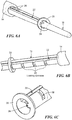
FIGS. 4, 5 and6A-6C , in a preferred embodiment, theelectrode carrier 12 includes agroove 22 disposed in a longitudinal direction along the distal end of theelectrode array 16. Theinsertion stopper 20 includes a protrusion or pin 24 on itsinner surface 20a that is positioned within thegroove 22 so that theinsertion stopper 20 is movable with respect to theelectrode carrier 12. Theelectrode carrier 12 may also include one ormore locking grooves 26 disposed in a transverse direction on theelectrode carrier 12. Theinsertion stopper 20 may be secured or locked at any predefined position on theelectrode array 16 by rotating theinsertion stopper 20 so that theprotrusion 24 moves from thelongitudinal groove 22 to the lockinggroove 26. - Although the
insertion stopper 20 has been shown with anouter surface 20b that is round or circular in shape, other configurations may also be used. For example, theinsertion stopper 20 may include an outer surface having one or more bulges orbeveled surfaces 28, such as shown inFIGS. 7A, 7B and 8 . If the configuration includes two beveled surfaces, then the diameter of the one beveled surface is preferably smaller than the diameter of the other surface, with the smaller beveled surface closer to the proximal end of theelectrode array 16. As shown inFIGS. 9A and 9B , theinsertion stopper 20 may have an outer surface shaped like one or more cone-shapedcylinders 30, with the smaller diameter portion of the cylinder closer to the proximal end of theelectrode array 16. This type of configuration allows the smaller beveled surface or the smaller diameter cylinder to be at the front of themovable stopper 20 so that it can enter the round window opening or cochleostomy, which permits theelectrode carrier 12 to be more readily affixed to the cochlea, so that any later movements of theelectrode carrier 12 after implantation can be minimized or prevented. - Although the outer surface of the
electrode carrier 12 and theinner surface 20b of theinsertion stopper 20 have been shown with a substantially round shape or circular cross-section, theelectrode carrier 12 andstopper 20 may have other shapes. Preferably, the inner surface of theinsertion stopper 20 is substantially similar in shape as the outer surface of theelectrode carrier 12. For example,FIGS. 10A and 10B schematically show anelectrode carrier 12 and aninsertion stopper 20 having at least one flat portion. As shown inFIG. 10B , thelongitudinal groove 22 may be disposed on aflat portion 12a of theelectrode carrier 12 and theprotrusion 24 may be positioned on aflat portion 20c of theinsertion stopper 20. For anelectrode carrier 12 which does not have a circular cross-section, the locking of theinsertion stopper 20 may be accomplished in a number of ways rather than using the lockinggrooves 26. For example, aclip 32 may be used that is secured to a position along theelectrode array 16, which prevents theinsertion stopper 20 from moving beyond that position toward a distal end of theelectrode carrier 12. Alternatively, theelectrode carrier 12 may have one ormore holes 34 located in the transverse direction along theelectrode array 16 and alocking pin 36 that fits within thehole 34, as shown inFIGS. 11A and 11B . This type of configuration also prevents theinsertion stopper 20 from moving beyond thepin 36 toward theelectrode lead 14 in the distal end of theelectrode carrier 12. Theclip 32 and the lockingpin 36 may be made of any biocompatible material such as biocompatible metal or any mechanically stable biocompatible polymer. - Although an
electrode carrier 12 with alongitudinal groove 22 is discussed above, other configurations may also be used that allow theinsertion stopper 20 to be readily moved along theelectrode array 16 and secured at different positions. For example, theelectrode carrier 12 may include one ormore grooves 38 disposed in the transverse direction along theelectrode array 16 and aninsertion stopper 40 that fits within thegrooves 38, such as shown inFIGS. 12A through 12C . As shown inFIG. 12B , in this embodiment, theinsertion stopper 40 does not have theprotrusion 24 on its inner surface as previously shown and discussed in connection withinsertion stopper 20. Thetransverse grooves 38 are located at predefined positions and theinsertion stopper 40 may be moved parallel to the longitudinal axis of theelectrode array 16 and positioned within any one of thegrooves 38. Theinsertion stopper 40 and theelectrode carrier 12 may be made of a biocompatible material, such as a silicone elastomer, which allows theinsertion stopper 40 to be easily slid over theelectrode carrier 12. - Other configurations of the
stopper FIGS. 13A - 13C show aninsertion stopper skirt 42 around its circumference. Theskirt 42 allows theelectrode carrier 12 to be affixed to nearby tissue when the device is implanted and also may serve as a cap to help close the opening in the round window or cochleostomy.FIG. 14A shows anelectrode carrier 12 assembled with aninsertion stopper 20 having askirt 42 andFIG. 14B schematically shows theelectrode array 16 implanted within the cochlear 114 with theinsertion stopper 20 provided near thecochleostomy 116. Instead of, or in addition to, theskirt 42, theinsertion stopper skirt 42 may be made of the same material as that of theinsertion stopper insertion stopper insertion stopper - As shown in
FIGS. 15A - 15E , theinsertion stopper band 44 that is embedded within theinsertion stopper band 44 may be made of any biocompatible material that is detectable in radiographs. When theinsertion stopper electrode array 16 is implanted in the cochlea, theband 44 serves as a radio marker to more accurately determine the location of theelectrode carrier 12 and cochleostomy in post-implantation radiographs. -
FIGS. 16A - 16D show anelectrode carrier 12 andmovable insertion stopper 20 configuration that covers and protects the electrode lead which reduces bacterial infection. In this embodiment, theelectrode carrier 12 includesnotches 46 and themovable insertion stopper 20 has aflexible region 48 that is configured to extend or contract depending on the relative position of thestopper 20 in relation to thecarrier 12. Themovable insertion stopper 20 is configured to fit over theelectrode lead 14 and includes a lockingpin 50 on its inner surface that is configured to engage with and be positioned within thenotches 46 on theelectrode carrier 12. Theinsertion stopper 20 may include aconical stopper region 52 at its proximal end and may be securely fixed to theelectrode carrier 12 at the distal end of thestopper 20, e.g., using silicone or other suitable fixing means. As shown inFIGS. 16C and 16D , theflexible region 48 allows theinsertion stopper 20 to expand or contract in length in order to accommodate the lockingpin 50 in thevarious notch 46 positions. Theinsertion stopper 20 may include aclip 54, e.g., a metallic clip, in its proximal end that is configured to open thestopper region 52 such that the lockingpin 50 disengages with thenotch 46. Theclip 54 may be detectable in radiographs and serve as a radio marker, similar to theband 44 previously described. Theclip 54 may be fixed to the nearby bone, tissue, or round window niche to prevent electrode spring back. In addition, theinsertion stopper 20 in this embodiment may further include askirt 42, such as shown and described with regard toFIGS. 13A- 13C . - Although the above discussion discloses various exemplary embodiments of the invention, it should be apparent that those skilled in the art can make various modifications that will achieve some of the advantages of these embodiments without departing from the true scope of the invention.
- Further aspects of the invention are illustrated by the following examples:
- Example 1: A cochlear implant electrode comprising:
- an electrode carrier having an electrode array with a groove disposed in a longitudinal direction along the electrode carrier; and
- a stopper positioned around the electrode carrier, the stopper having a protrusion on an inner surface of the stopper, the protrusion configured to be positioned within the groove so that the stopper is movable with respect to the electrode carrier.
- Example 2: The electrode of example 1, wherein the electrode array further includes at least one locking groove disposed in a transverse direction such that the stopper is movable within the groove and within the locking groove.
- Example 3: The electrode of example 1, wherein the stopper further includes a skirt around an outer surface of the stopper, the skirt configured to cover at least a portion of a cochleostomy site.
- Example 4: The electrode of example 1, wherein the stopper includes an outer surface having two beveled surfaces, wherein one beveled surface has a smaller diameter than the other beveled surface.
- Example 5: The electrode of example 1, wherein the stopper includes an outer surface having a shape of at least one cone-shaped cylinder.
- Example 6: The electrode of example 1, wherein the stopper further includes a band disposed inside the stopper, the band made of a material that is detectable in radiographs.
- Example 7: The electrode of example 6, wherein the band is made of metal.
- Example 8: The electrode of example 1, further comprising a clip secured to a position along the electrode array so that the stopper is prevented from moving beyond the position toward a distal end of the electrode carrier.
- Example 9: The electrode of example 1, wherein the electrode array further includes at least one hole disposed in a transverse direction along the electrode carrier, the electrode further comprising a pin configured to fit within the hole so that the stopper is prevented from moving beyond the pin toward the distal end of the electrode carrier.
- Example 10: The electrode of example 1, wherein the inner surface of the stopper is substantially round in shape.
- Example 11: The electrode of example 1, wherein the inner surface of the stopper is substantially similar in shape as an outer surface of the electrode carrier.
- Example 12: The electrode of example 11, wherein the inner surface of the stopper includes a flat portion and the outer surface of the electrode carrier includes a flat portion.
- Example 13: The electrode of example 12, wherein the groove is disposed on the flat portion of the electrode carrier and the protrusion is disposed on the flat portion of the stopper.
- Example 14: The electrode of example 1, wherein the stopper includes a drug that is released from the stopper in order to prevent bacterial infection or fibrous tissue formation.
- Example 15: A cochlear implant electrode comprising:
- an electrode carrier having an electrode array with grooves, each groove disposed in a transverse direction along the electrode carrier; and
- a stopper positioned around the electrode carrier, the stopper configured to be positioned within each groove and movable with respect to the electrode carrier.
- Example 16: The electrode of example 15, wherein the stopper further includes a skirt around an outer surface of the stopper, the skirt configured to cover at least a portion of a cochleostomy site.
- Example 17: The electrode of example 15, wherein the stopper further includes a band disposed inside the stopper, the band made of a material that is detectable in radiographs.
- Example 18: The electrode of example 15, wherein the stopper includes an outer surface having two beveled surfaces, wherein one beveled surface has a smaller diameter than the other beveled surface.
- Example 19: The electrode of example 15, wherein the stopper includes an outer surface having a shape of at least one cone-shaped cylinder.
- Example 20: The electrode of example 15, wherein the stopper includes a drug that is released from the stopper in order to prevent bacterial infection or fibrous tissue formation.
- Example 21: A cochlear implant electrode comprising:
- an electrode carrier having an electrode array with notches disposed longitudinally along the electrode carrier; and
- a stopper positioned over the electrode carrier, the stopper having a locking pin on an inner surface of its proximal end, the locking pin configured to be positioned within each notch and movable with respect to the electrode carrier, the stopper further including a flexible region configured to allow the stopper to expand or contract in length when the locking pin is moved with respect to the electrode carrier.
- Example 22: The electrode of example 21, wherein the stopper further includes a skirt around an outer surface of the stopper, the skirt configured to cover at least a portion of a cochleostomy site.
- Example 23: The electrode of example 21, wherein the stopper is fixed to the electrode carrier at a distal end of the stopper.
- Example 24: The electrode of example 21, wherein the stopper further includes a clip in its proximal end that is configured to open the stopper such that the locking pin disengages with the notch.
- Example 25: The electrode of example 24, wherein the clip is made of a material that is detectable in radiographs.
- Example 26: The electrode of example 21, wherein the stopper includes a drug that is released from the stopper in order to prevent bacterial infection or fibrous tissue formation.
Claims (15)
- A cochlear implant electrode comprising:an electrode carrier having an electrode lead at its distal end and an electrode array with stimulating electrodes distributed along the electrode array at its proximal end, the electrode carrier including notches disposed in a longitudinal direction along the electrode carrier; anda stopper fixed to the electrode carrier at its distal end, the stopper having a locking pin on an inner surface of the stopper configured to be positioned within the notches and having a region that is configured to extend or contract so that the stopper expands or contracts in length in relation to the electrode carrier depending on a position of the locking pin in one of the notches and so that a proximal end of the stopper is movable with respect to the electrode carrier.
- The electrode of claim 1, wherein the stopper includes a stopper region at its proximal end, the locking pin located within the stopper region.
- The electrode of claim 2, wherein the stopper in the stopper region has a smaller outer diameter than the stopper at its distal end.
- The electrode of claim 2, wherein the stopper further includes a clip at its proximal end that is configured to open the stopper region and to disengage the locking pin from one of the notches.
- The electrode of claim 4, wherein a portion of the clip is disposed inside the stopper and a portion of the clip protrudes from the stopper and is configured to allow a user to open the stopper region.
- The electrode of claim 4, wherein the clip is made of a material that is detectable in radiographs.
- The electrode of claim 6, wherein the clip is made of metal.
- The electrode of claim 4, wherein the portion of the clip that protrudes from the stopper is configured to be fixed to nearby bone, tissue, or round window niche so that the electrode is prevented from spring back.
- The electrode of claim 1, wherein the stopper has a zig zag pattern shape in the region that allows the stopper to expand or contract in length.
- The electrode of claim 1, wherein a portion of the stopper is configured to fit over the electrode lead.
- The electrode of claim 1, wherein the stopper includes a drug that is released from the stopper in order to prevent bacterial infection or fibrous tissue formation.
- A cochlear implant electrode comprising:an electrode carrier having an electrode array with notches disposed longitudinally along the electrode carrier; anda stopper positioned over the electrode carrier, the stopper having a locking pin on an inner surface of its proximal end, the locking pin configured to be positioned within each notch and movable with respect to the electrode carrier, the stopper further including a flexible region configured to allow the stopper to expand or contract in length when the locking pin is moved with respect to the electrode carrier.
- The electrode of claim 12, wherein the stopper further includes a skirt around an outer surface of the stopper, the skirt configured to cover at least a portion of a cochleostomy site.
- The electrode of claim 12, wherein the stopper is fixed to the electrode carrier at a distal end of the stopper.
- The electrode of claim 12, wherein the stopper further includes a clip in its proximal end that is configured to open the stopper such that the locking pin disengages with the notch, wherein the clip is preferably made of a material that is detectable in radiographs, or wherein the stopper includes a drug that is released from the stopper in order to prevent bacterial infection or fibrous tissue formation.
Applications Claiming Priority (3)
| Application Number | Priority Date | Filing Date | Title |
|---|---|---|---|
| US201261657270P | 2012-06-08 | 2012-06-08 | |
| PCT/US2013/044228 WO2013184750A2 (en) | 2012-06-08 | 2013-06-05 | Electrode with movable insertion stopper |
| EP13729217.3A EP2858714B1 (en) | 2012-06-08 | 2013-06-05 | Electrode with movable insertion stopper |
Related Parent Applications (1)
| Application Number | Title | Priority Date | Filing Date |
|---|---|---|---|
| EP13729217.3A Division EP2858714B1 (en) | 2012-06-08 | 2013-06-05 | Electrode with movable insertion stopper |
Publications (2)
| Publication Number | Publication Date |
|---|---|
| EP3590575A1 true EP3590575A1 (en) | 2020-01-08 |
| EP3590575B1 EP3590575B1 (en) | 2023-05-03 |
Family
ID=48626681
Family Applications (2)
| Application Number | Title | Priority Date | Filing Date |
|---|---|---|---|
| EP13729217.3A Active EP2858714B1 (en) | 2012-06-08 | 2013-06-05 | Electrode with movable insertion stopper |
| EP19192549.4A Active EP3590575B1 (en) | 2012-06-08 | 2013-06-05 | Electrode with movable insertion stopper |
Family Applications Before (1)
| Application Number | Title | Priority Date | Filing Date |
|---|---|---|---|
| EP13729217.3A Active EP2858714B1 (en) | 2012-06-08 | 2013-06-05 | Electrode with movable insertion stopper |
Country Status (5)
| Country | Link |
|---|---|
| US (2) | US8934985B2 (en) |
| EP (2) | EP2858714B1 (en) |
| CN (2) | CN106178260B (en) |
| AU (2) | AU2013271726B2 (en) |
| WO (1) | WO2013184750A2 (en) |
Families Citing this family (18)
| Publication number | Priority date | Publication date | Assignee | Title |
|---|---|---|---|---|
| EP2858714B1 (en) | 2012-06-08 | 2019-08-21 | MED-EL Elektromedizinische Geräte GmbH | Electrode with movable insertion stopper |
| AU2015217381B2 (en) * | 2014-02-11 | 2017-03-16 | Med-El Elektromedizinische Geraete Gmbh | Electrode with anti-spring back component |
| WO2016035027A1 (en) | 2014-09-02 | 2016-03-10 | Cochlear Limited | Intra-cochlear stimulating assembly insertion |
| WO2016035026A1 (en) | 2014-09-02 | 2016-03-10 | Cochlear Limited | Event detection in an implantable auditory prosthesis |
| CA2986014A1 (en) * | 2015-05-12 | 2016-11-17 | Zipline Health, Inc. | Devices, methods, and systems for acquiring medical diagnostic information and provision of telehealth services |
| WO2017011639A1 (en) * | 2015-07-15 | 2017-01-19 | Med-El Elektromedizinische Geraete Gmbh | Electrode lead that avoids electrode array migration from the cochlea |
| CN105169553B (en) * | 2015-08-05 | 2017-12-08 | 苏州景昱医疗器械有限公司 | Electrode cable protection device |
| US12011594B2 (en) | 2015-09-14 | 2024-06-18 | Iotamotion, Inc. | Modular implant delivery and positioning system |
| US11241576B2 (en) | 2015-09-14 | 2022-02-08 | University Of Iowa Research Foundation | Controlled position electrode array |
| EP3528759B1 (en) * | 2016-10-24 | 2020-12-23 | Med-El Elektromedizinische Geraete GmbH | A fixation component for insertion tools for minimally invasive cochlear implants |
| CN110430918B (en) | 2017-02-14 | 2023-06-13 | 约塔莫绅有限公司 | Modular Implant Delivery and Positioning System |
| US10945761B2 (en) | 2017-02-14 | 2021-03-16 | Iotamotion, Inc. | Modular implant delivery and positioning system |
| US11439749B2 (en) * | 2017-10-25 | 2022-09-13 | The Charles Stark Draper Laboratory, Inc. | Apparatus and method for trans-round window membrane drug delivery |
| US11433246B2 (en) | 2017-11-30 | 2022-09-06 | Advanced Bionics Ag | Slotted stiffening member for facilitating an insertion of an electrode lead into a cochlea of a patient |
| EP3773871B1 (en) * | 2018-04-13 | 2022-12-14 | Advanced Bionics AG | Pull wire displacement assemblies |
| WO2021059016A1 (en) * | 2019-09-23 | 2021-04-01 | Cochlear Limited | Detection and treatment of neotissue |
| CN115038398A (en) | 2019-09-30 | 2022-09-09 | 约塔莫绅有限公司 | Modular implant delivery and positioning system |
| CN113262900A (en) * | 2021-05-12 | 2021-08-17 | 上海大学 | Hollowed-out clamping die for spraying medicine on ear electrode and using method of hollowed-out clamping die |
Citations (4)
| Publication number | Priority date | Publication date | Assignee | Title |
|---|---|---|---|---|
| WO2004004413A1 (en) * | 2002-06-28 | 2004-01-08 | Cochlear Limited | Cochlear implant electrode array |
| US20080119920A1 (en) * | 2003-04-16 | 2008-05-22 | Cochlear Limited | Cochlear electrode array |
| US20110245891A1 (en) * | 2010-03-30 | 2011-10-06 | Fritsch Michael H | Cochlear implant stabilization and positioning device |
| US20110301681A1 (en) * | 2006-09-29 | 2011-12-08 | Frank Risi | Electrode assembly for a stimulating medical device |
Family Cites Families (6)
| Publication number | Priority date | Publication date | Assignee | Title |
|---|---|---|---|---|
| US7792586B2 (en) * | 2002-02-22 | 2010-09-07 | Cochlear Limited | Insertion device for an electrode array |
| AR059786A1 (en) * | 2006-03-09 | 2008-04-30 | Med El Elektromed Geraete Gmbh | CONFIGURATION OF COCLEAR IMPLANT ELECTRODE TO ELECT PHARMACOS |
| US8718795B2 (en) * | 2007-03-20 | 2014-05-06 | Cochlear Limited | Securing an implanted medical device in a patient |
| CN101366666A (en) * | 2008-09-12 | 2009-02-18 | 上海力声特医学科技有限公司 | Pre-bend electrode array couplet for cochlear implant |
| EP2451366B1 (en) | 2009-07-08 | 2017-03-15 | Advanced Bionics AG | Lead insertion tools |
| EP2858714B1 (en) | 2012-06-08 | 2019-08-21 | MED-EL Elektromedizinische Geräte GmbH | Electrode with movable insertion stopper |
-
2013
- 2013-06-05 EP EP13729217.3A patent/EP2858714B1/en active Active
- 2013-06-05 EP EP19192549.4A patent/EP3590575B1/en active Active
- 2013-06-05 AU AU2013271726A patent/AU2013271726B2/en active Active
- 2013-06-05 US US13/910,408 patent/US8934985B2/en active Active
- 2013-06-05 CN CN201610643440.8A patent/CN106178260B/en active Active
- 2013-06-05 CN CN201380030216.6A patent/CN104363952B/en active Active
- 2013-06-05 WO PCT/US2013/044228 patent/WO2013184750A2/en not_active Ceased
-
2015
- 2015-01-07 US US14/591,364 patent/US9155880B2/en active Active
-
2016
- 2016-07-26 AU AU2016208274A patent/AU2016208274B2/en active Active
Patent Citations (4)
| Publication number | Priority date | Publication date | Assignee | Title |
|---|---|---|---|---|
| WO2004004413A1 (en) * | 2002-06-28 | 2004-01-08 | Cochlear Limited | Cochlear implant electrode array |
| US20080119920A1 (en) * | 2003-04-16 | 2008-05-22 | Cochlear Limited | Cochlear electrode array |
| US20110301681A1 (en) * | 2006-09-29 | 2011-12-08 | Frank Risi | Electrode assembly for a stimulating medical device |
| US20110245891A1 (en) * | 2010-03-30 | 2011-10-06 | Fritsch Michael H | Cochlear implant stabilization and positioning device |
Also Published As
| Publication number | Publication date |
|---|---|
| CN104363952B (en) | 2016-08-24 |
| AU2016208274A1 (en) | 2016-08-18 |
| WO2013184750A3 (en) | 2014-03-27 |
| EP2858714A2 (en) | 2015-04-15 |
| CN106178260A (en) | 2016-12-07 |
| AU2016208274B2 (en) | 2017-09-07 |
| WO2013184750A2 (en) | 2013-12-12 |
| US9155880B2 (en) | 2015-10-13 |
| CN106178260B (en) | 2018-10-30 |
| CN104363952A (en) | 2015-02-18 |
| EP2858714B1 (en) | 2019-08-21 |
| US20150119791A1 (en) | 2015-04-30 |
| US20130331779A1 (en) | 2013-12-12 |
| AU2013271726B2 (en) | 2016-05-12 |
| AU2013271726A1 (en) | 2015-01-22 |
| EP3590575B1 (en) | 2023-05-03 |
| US8934985B2 (en) | 2015-01-13 |
Similar Documents
| Publication | Publication Date | Title |
|---|---|---|
| US8934985B2 (en) | Electrode with movable insertion stopper | |
| EP2457386B1 (en) | Integrated wire carrier for electrode array | |
| US9037267B2 (en) | Cochlear lead | |
| US12465755B2 (en) | Neural stimulator with flying lead electrode | |
| US9480838B2 (en) | Cochlear electrode with apical lateral wall section and basal modiolar hugging section | |
| US9707388B2 (en) | Electrode lead with integrated attachment mechanism | |
| US11484704B2 (en) | Implanted medical devices having electrode assemblies | |
| US9888978B2 (en) | Template for bilateral symmetric stimulator fixation/implantation | |
| US20180104473A1 (en) | Cochlear electrode array with a flexural inflection point | |
| US10213597B2 (en) | Electrode lead that avoids electrode array migration from the cochlea | |
| US20060178720A1 (en) | Method and apparatus for sealing a lumen in an electrode assembly | |
| US20230091164A1 (en) | Cochlear implant electrode arrays having orientation indicators and cochlear implants including the same | |
| AU2003287772A1 (en) | Method and apparatus for sealing a lumen in an electrode assembly |
Legal Events
| Date | Code | Title | Description |
|---|---|---|---|
| PUAI | Public reference made under article 153(3) epc to a published international application that has entered the european phase |
Free format text: ORIGINAL CODE: 0009012 |
|
| STAA | Information on the status of an ep patent application or granted ep patent |
Free format text: STATUS: THE APPLICATION HAS BEEN PUBLISHED |
|
| AC | Divisional application: reference to earlier application |
Ref document number: 2858714 Country of ref document: EP Kind code of ref document: P |
|
| AK | Designated contracting states |
Kind code of ref document: A1 Designated state(s): AL AT BE BG CH CY CZ DE DK EE ES FI FR GB GR HR HU IE IS IT LI LT LU LV MC MK MT NL NO PL PT RO RS SE SI SK SM TR |
|
| RIN1 | Information on inventor provided before grant (corrected) |
Inventor name: DHANASINGH, ANANDHAN Inventor name: JOLLY, CLAUDE |
|
| STAA | Information on the status of an ep patent application or granted ep patent |
Free format text: STATUS: REQUEST FOR EXAMINATION WAS MADE |
|
| 17P | Request for examination filed |
Effective date: 20200324 |
|
| RBV | Designated contracting states (corrected) |
Designated state(s): AL AT BE BG CH CY CZ DE DK EE ES FI FR GB GR HR HU IE IS IT LI LT LU LV MC MK MT NL NO PL PT RO RS SE SI SK SM TR |
|
| GRAP | Despatch of communication of intention to grant a patent |
Free format text: ORIGINAL CODE: EPIDOSNIGR1 |
|
| STAA | Information on the status of an ep patent application or granted ep patent |
Free format text: STATUS: GRANT OF PATENT IS INTENDED |
|
| RIC1 | Information provided on ipc code assigned before grant |
Ipc: A61B 17/34 20060101ALN20221217BHEP Ipc: A61N 1/05 20060101AFI20221217BHEP |
|
| INTG | Intention to grant announced |
Effective date: 20230123 |
|
| GRAS | Grant fee paid |
Free format text: ORIGINAL CODE: EPIDOSNIGR3 |
|
| GRAA | (expected) grant |
Free format text: ORIGINAL CODE: 0009210 |
|
| STAA | Information on the status of an ep patent application or granted ep patent |
Free format text: STATUS: THE PATENT HAS BEEN GRANTED |
|
| AC | Divisional application: reference to earlier application |
Ref document number: 2858714 Country of ref document: EP Kind code of ref document: P |
|
| AK | Designated contracting states |
Kind code of ref document: B1 Designated state(s): AL AT BE BG CH CY CZ DE DK EE ES FI FR GB GR HR HU IE IS IT LI LT LU LV MC MK MT NL NO PL PT RO RS SE SI SK SM TR |
|
| REG | Reference to a national code |
Ref country code: GB Ref legal event code: FG4D |
|
| REG | Reference to a national code |
Ref country code: DE Ref legal event code: R096 Ref document number: 602013083743 Country of ref document: DE |
|
| REG | Reference to a national code |
Ref country code: AT Ref legal event code: REF Ref document number: 1564070 Country of ref document: AT Kind code of ref document: T Effective date: 20230515 Ref country code: CH Ref legal event code: EP |
|
| REG | Reference to a national code |
Ref country code: IE Ref legal event code: FG4D |
|
| REG | Reference to a national code |
Ref country code: LT Ref legal event code: MG9D |
|
| REG | Reference to a national code |
Ref country code: NL Ref legal event code: MP Effective date: 20230503 |
|
| REG | Reference to a national code |
Ref country code: AT Ref legal event code: MK05 Ref document number: 1564070 Country of ref document: AT Kind code of ref document: T Effective date: 20230503 |
|
| PG25 | Lapsed in a contracting state [announced via postgrant information from national office to epo] |
Ref country code: SE Free format text: LAPSE BECAUSE OF FAILURE TO SUBMIT A TRANSLATION OF THE DESCRIPTION OR TO PAY THE FEE WITHIN THE PRESCRIBED TIME-LIMIT Effective date: 20230503 Ref country code: PT Free format text: LAPSE BECAUSE OF FAILURE TO SUBMIT A TRANSLATION OF THE DESCRIPTION OR TO PAY THE FEE WITHIN THE PRESCRIBED TIME-LIMIT Effective date: 20230904 Ref country code: NO Free format text: LAPSE BECAUSE OF FAILURE TO SUBMIT A TRANSLATION OF THE DESCRIPTION OR TO PAY THE FEE WITHIN THE PRESCRIBED TIME-LIMIT Effective date: 20230803 Ref country code: NL Free format text: LAPSE BECAUSE OF FAILURE TO SUBMIT A TRANSLATION OF THE DESCRIPTION OR TO PAY THE FEE WITHIN THE PRESCRIBED TIME-LIMIT Effective date: 20230503 Ref country code: ES Free format text: LAPSE BECAUSE OF FAILURE TO SUBMIT A TRANSLATION OF THE DESCRIPTION OR TO PAY THE FEE WITHIN THE PRESCRIBED TIME-LIMIT Effective date: 20230503 Ref country code: AT Free format text: LAPSE BECAUSE OF FAILURE TO SUBMIT A TRANSLATION OF THE DESCRIPTION OR TO PAY THE FEE WITHIN THE PRESCRIBED TIME-LIMIT Effective date: 20230503 |
|
| PG25 | Lapsed in a contracting state [announced via postgrant information from national office to epo] |
Ref country code: RS Free format text: LAPSE BECAUSE OF FAILURE TO SUBMIT A TRANSLATION OF THE DESCRIPTION OR TO PAY THE FEE WITHIN THE PRESCRIBED TIME-LIMIT Effective date: 20230503 Ref country code: PL Free format text: LAPSE BECAUSE OF FAILURE TO SUBMIT A TRANSLATION OF THE DESCRIPTION OR TO PAY THE FEE WITHIN THE PRESCRIBED TIME-LIMIT Effective date: 20230503 Ref country code: LV Free format text: LAPSE BECAUSE OF FAILURE TO SUBMIT A TRANSLATION OF THE DESCRIPTION OR TO PAY THE FEE WITHIN THE PRESCRIBED TIME-LIMIT Effective date: 20230503 Ref country code: LT Free format text: LAPSE BECAUSE OF FAILURE TO SUBMIT A TRANSLATION OF THE DESCRIPTION OR TO PAY THE FEE WITHIN THE PRESCRIBED TIME-LIMIT Effective date: 20230503 Ref country code: IS Free format text: LAPSE BECAUSE OF FAILURE TO SUBMIT A TRANSLATION OF THE DESCRIPTION OR TO PAY THE FEE WITHIN THE PRESCRIBED TIME-LIMIT Effective date: 20230903 Ref country code: HR Free format text: LAPSE BECAUSE OF FAILURE TO SUBMIT A TRANSLATION OF THE DESCRIPTION OR TO PAY THE FEE WITHIN THE PRESCRIBED TIME-LIMIT Effective date: 20230503 Ref country code: GR Free format text: LAPSE BECAUSE OF FAILURE TO SUBMIT A TRANSLATION OF THE DESCRIPTION OR TO PAY THE FEE WITHIN THE PRESCRIBED TIME-LIMIT Effective date: 20230804 |
|
| PG25 | Lapsed in a contracting state [announced via postgrant information from national office to epo] |
Ref country code: FI Free format text: LAPSE BECAUSE OF FAILURE TO SUBMIT A TRANSLATION OF THE DESCRIPTION OR TO PAY THE FEE WITHIN THE PRESCRIBED TIME-LIMIT Effective date: 20230503 |
|
| PG25 | Lapsed in a contracting state [announced via postgrant information from national office to epo] |
Ref country code: SK Free format text: LAPSE BECAUSE OF FAILURE TO SUBMIT A TRANSLATION OF THE DESCRIPTION OR TO PAY THE FEE WITHIN THE PRESCRIBED TIME-LIMIT Effective date: 20230503 |
|
| PG25 | Lapsed in a contracting state [announced via postgrant information from national office to epo] |
Ref country code: SM Free format text: LAPSE BECAUSE OF FAILURE TO SUBMIT A TRANSLATION OF THE DESCRIPTION OR TO PAY THE FEE WITHIN THE PRESCRIBED TIME-LIMIT Effective date: 20230503 Ref country code: SK Free format text: LAPSE BECAUSE OF FAILURE TO SUBMIT A TRANSLATION OF THE DESCRIPTION OR TO PAY THE FEE WITHIN THE PRESCRIBED TIME-LIMIT Effective date: 20230503 Ref country code: RO Free format text: LAPSE BECAUSE OF FAILURE TO SUBMIT A TRANSLATION OF THE DESCRIPTION OR TO PAY THE FEE WITHIN THE PRESCRIBED TIME-LIMIT Effective date: 20230503 Ref country code: EE Free format text: LAPSE BECAUSE OF FAILURE TO SUBMIT A TRANSLATION OF THE DESCRIPTION OR TO PAY THE FEE WITHIN THE PRESCRIBED TIME-LIMIT Effective date: 20230503 Ref country code: DK Free format text: LAPSE BECAUSE OF FAILURE TO SUBMIT A TRANSLATION OF THE DESCRIPTION OR TO PAY THE FEE WITHIN THE PRESCRIBED TIME-LIMIT Effective date: 20230503 Ref country code: CZ Free format text: LAPSE BECAUSE OF FAILURE TO SUBMIT A TRANSLATION OF THE DESCRIPTION OR TO PAY THE FEE WITHIN THE PRESCRIBED TIME-LIMIT Effective date: 20230503 |
|
| REG | Reference to a national code |
Ref country code: CH Ref legal event code: PL |
|
| REG | Reference to a national code |
Ref country code: DE Ref legal event code: R097 Ref document number: 602013083743 Country of ref document: DE |
|
| REG | Reference to a national code |
Ref country code: BE Ref legal event code: MM Effective date: 20230630 |
|
| PG25 | Lapsed in a contracting state [announced via postgrant information from national office to epo] |
Ref country code: MC Free format text: LAPSE BECAUSE OF FAILURE TO SUBMIT A TRANSLATION OF THE DESCRIPTION OR TO PAY THE FEE WITHIN THE PRESCRIBED TIME-LIMIT Effective date: 20230503 |
|
| PG25 | Lapsed in a contracting state [announced via postgrant information from national office to epo] |
Ref country code: MC Free format text: LAPSE BECAUSE OF FAILURE TO SUBMIT A TRANSLATION OF THE DESCRIPTION OR TO PAY THE FEE WITHIN THE PRESCRIBED TIME-LIMIT Effective date: 20230503 |
|
| PG25 | Lapsed in a contracting state [announced via postgrant information from national office to epo] |
Ref country code: LU Free format text: LAPSE BECAUSE OF NON-PAYMENT OF DUE FEES Effective date: 20230605 |
|
| PLBE | No opposition filed within time limit |
Free format text: ORIGINAL CODE: 0009261 |
|
| STAA | Information on the status of an ep patent application or granted ep patent |
Free format text: STATUS: NO OPPOSITION FILED WITHIN TIME LIMIT |
|
| REG | Reference to a national code |
Ref country code: IE Ref legal event code: MM4A |
|
| PG25 | Lapsed in a contracting state [announced via postgrant information from national office to epo] |
Ref country code: LU Free format text: LAPSE BECAUSE OF NON-PAYMENT OF DUE FEES Effective date: 20230605 |
|
| 26N | No opposition filed |
Effective date: 20240206 |
|
| PG25 | Lapsed in a contracting state [announced via postgrant information from national office to epo] |
Ref country code: IE Free format text: LAPSE BECAUSE OF NON-PAYMENT OF DUE FEES Effective date: 20230605 |
|
| GBPC | Gb: european patent ceased through non-payment of renewal fee |
Effective date: 20230803 |
|
| PG25 | Lapsed in a contracting state [announced via postgrant information from national office to epo] |
Ref country code: IE Free format text: LAPSE BECAUSE OF NON-PAYMENT OF DUE FEES Effective date: 20230605 Ref country code: CH Free format text: LAPSE BECAUSE OF NON-PAYMENT OF DUE FEES Effective date: 20230630 |
|
| PG25 | Lapsed in a contracting state [announced via postgrant information from national office to epo] |
Ref country code: SI Free format text: LAPSE BECAUSE OF FAILURE TO SUBMIT A TRANSLATION OF THE DESCRIPTION OR TO PAY THE FEE WITHIN THE PRESCRIBED TIME-LIMIT Effective date: 20230503 |
|
| PG25 | Lapsed in a contracting state [announced via postgrant information from national office to epo] |
Ref country code: SI Free format text: LAPSE BECAUSE OF FAILURE TO SUBMIT A TRANSLATION OF THE DESCRIPTION OR TO PAY THE FEE WITHIN THE PRESCRIBED TIME-LIMIT Effective date: 20230503 Ref country code: IT Free format text: LAPSE BECAUSE OF FAILURE TO SUBMIT A TRANSLATION OF THE DESCRIPTION OR TO PAY THE FEE WITHIN THE PRESCRIBED TIME-LIMIT Effective date: 20230503 Ref country code: BE Free format text: LAPSE BECAUSE OF NON-PAYMENT OF DUE FEES Effective date: 20230630 |
|
| PG25 | Lapsed in a contracting state [announced via postgrant information from national office to epo] |
Ref country code: GB Free format text: LAPSE BECAUSE OF NON-PAYMENT OF DUE FEES Effective date: 20230803 |
|
| PG25 | Lapsed in a contracting state [announced via postgrant information from national office to epo] |
Ref country code: GB Free format text: LAPSE BECAUSE OF NON-PAYMENT OF DUE FEES Effective date: 20230803 |
|
| PG25 | Lapsed in a contracting state [announced via postgrant information from national office to epo] |
Ref country code: BG Free format text: LAPSE BECAUSE OF FAILURE TO SUBMIT A TRANSLATION OF THE DESCRIPTION OR TO PAY THE FEE WITHIN THE PRESCRIBED TIME-LIMIT Effective date: 20230503 |
|
| PG25 | Lapsed in a contracting state [announced via postgrant information from national office to epo] |
Ref country code: BG Free format text: LAPSE BECAUSE OF FAILURE TO SUBMIT A TRANSLATION OF THE DESCRIPTION OR TO PAY THE FEE WITHIN THE PRESCRIBED TIME-LIMIT Effective date: 20230503 |
|
| PGFP | Annual fee paid to national office [announced via postgrant information from national office to epo] |
Ref country code: DE Payment date: 20250626 Year of fee payment: 13 |
|
| PGFP | Annual fee paid to national office [announced via postgrant information from national office to epo] |
Ref country code: FR Payment date: 20250624 Year of fee payment: 13 |
|
| PG25 | Lapsed in a contracting state [announced via postgrant information from national office to epo] |
Ref country code: CY Free format text: LAPSE BECAUSE OF FAILURE TO SUBMIT A TRANSLATION OF THE DESCRIPTION OR TO PAY THE FEE WITHIN THE PRESCRIBED TIME-LIMIT; INVALID AB INITIO Effective date: 20130605 |
|
| PG25 | Lapsed in a contracting state [announced via postgrant information from national office to epo] |
Ref country code: HU Free format text: LAPSE BECAUSE OF FAILURE TO SUBMIT A TRANSLATION OF THE DESCRIPTION OR TO PAY THE FEE WITHIN THE PRESCRIBED TIME-LIMIT; INVALID AB INITIO Effective date: 20130605 |
|
| PG25 | Lapsed in a contracting state [announced via postgrant information from national office to epo] |
Ref country code: TR Free format text: LAPSE BECAUSE OF FAILURE TO SUBMIT A TRANSLATION OF THE DESCRIPTION OR TO PAY THE FEE WITHIN THE PRESCRIBED TIME-LIMIT Effective date: 20230503 |