EP3590571B1 - Appareil d'assistance respiratoire avec confinement de liquide - Google Patents
Appareil d'assistance respiratoire avec confinement de liquide Download PDFInfo
- Publication number
- EP3590571B1 EP3590571B1 EP19192027.1A EP19192027A EP3590571B1 EP 3590571 B1 EP3590571 B1 EP 3590571B1 EP 19192027 A EP19192027 A EP 19192027A EP 3590571 B1 EP3590571 B1 EP 3590571B1
- Authority
- EP
- European Patent Office
- Prior art keywords
- opening
- liquid containment
- containment compartment
- compartment
- assistance apparatus
- Prior art date
- Legal status (The legal status is an assumption and is not a legal conclusion. Google has not performed a legal analysis and makes no representation as to the accuracy of the status listed.)
- Active
Links
- 239000007788 liquid Substances 0.000 title claims description 65
- 230000029058 respiratory gaseous exchange Effects 0.000 title claims description 42
- 239000007789 gas Substances 0.000 claims description 24
- XLYOFNOQVPJJNP-UHFFFAOYSA-N water Substances O XLYOFNOQVPJJNP-UHFFFAOYSA-N 0.000 description 10
- 230000000241 respiratory effect Effects 0.000 description 9
- NJPPVKZQTLUDBO-UHFFFAOYSA-N novaluron Chemical compound C1=C(Cl)C(OC(F)(F)C(OC(F)(F)F)F)=CC=C1NC(=O)NC(=O)C1=C(F)C=CC=C1F NJPPVKZQTLUDBO-UHFFFAOYSA-N 0.000 description 7
- 238000010438 heat treatment Methods 0.000 description 6
- 238000010276 construction Methods 0.000 description 4
- 239000003570 air Substances 0.000 description 3
- 239000000463 material Substances 0.000 description 3
- 238000001764 infiltration Methods 0.000 description 2
- 230000008595 infiltration Effects 0.000 description 2
- 238000002955 isolation Methods 0.000 description 2
- 239000012080 ambient air Substances 0.000 description 1
- 230000006835 compression Effects 0.000 description 1
- 238000007906 compression Methods 0.000 description 1
- 238000000151 deposition Methods 0.000 description 1
- 230000003993 interaction Effects 0.000 description 1
- 230000005012 migration Effects 0.000 description 1
- 238000013508 migration Methods 0.000 description 1
- 239000012858 resilient material Substances 0.000 description 1
- 238000011144 upstream manufacturing Methods 0.000 description 1
Images


Classifications
-
- A—HUMAN NECESSITIES
- A61—MEDICAL OR VETERINARY SCIENCE; HYGIENE
- A61M—DEVICES FOR INTRODUCING MEDIA INTO, OR ONTO, THE BODY; DEVICES FOR TRANSDUCING BODY MEDIA OR FOR TAKING MEDIA FROM THE BODY; DEVICES FOR PRODUCING OR ENDING SLEEP OR STUPOR
- A61M16/00—Devices for influencing the respiratory system of patients by gas treatment, e.g. mouth-to-mouth respiration; Tracheal tubes
- A61M16/10—Preparation of respiratory gases or vapours
- A61M16/14—Preparation of respiratory gases or vapours by mixing different fluids, one of them being in a liquid phase
- A61M16/16—Devices to humidify the respiration air
-
- A—HUMAN NECESSITIES
- A61—MEDICAL OR VETERINARY SCIENCE; HYGIENE
- A61M—DEVICES FOR INTRODUCING MEDIA INTO, OR ONTO, THE BODY; DEVICES FOR TRANSDUCING BODY MEDIA OR FOR TAKING MEDIA FROM THE BODY; DEVICES FOR PRODUCING OR ENDING SLEEP OR STUPOR
- A61M16/00—Devices for influencing the respiratory system of patients by gas treatment, e.g. mouth-to-mouth respiration; Tracheal tubes
- A61M16/0057—Pumps therefor
- A61M16/0066—Blowers or centrifugal pumps
-
- A—HUMAN NECESSITIES
- A61—MEDICAL OR VETERINARY SCIENCE; HYGIENE
- A61M—DEVICES FOR INTRODUCING MEDIA INTO, OR ONTO, THE BODY; DEVICES FOR TRANSDUCING BODY MEDIA OR FOR TAKING MEDIA FROM THE BODY; DEVICES FOR PRODUCING OR ENDING SLEEP OR STUPOR
- A61M16/00—Devices for influencing the respiratory system of patients by gas treatment, e.g. mouth-to-mouth respiration; Tracheal tubes
- A61M16/08—Bellows; Connecting tubes ; Water traps; Patient circuits
- A61M16/0875—Connecting tubes
-
- A—HUMAN NECESSITIES
- A61—MEDICAL OR VETERINARY SCIENCE; HYGIENE
- A61M—DEVICES FOR INTRODUCING MEDIA INTO, OR ONTO, THE BODY; DEVICES FOR TRANSDUCING BODY MEDIA OR FOR TAKING MEDIA FROM THE BODY; DEVICES FOR PRODUCING OR ENDING SLEEP OR STUPOR
- A61M16/00—Devices for influencing the respiratory system of patients by gas treatment, e.g. mouth-to-mouth respiration; Tracheal tubes
- A61M16/10—Preparation of respiratory gases or vapours
- A61M16/1075—Preparation of respiratory gases or vapours by influencing the temperature
- A61M16/109—Preparation of respiratory gases or vapours by influencing the temperature the humidifying liquid or the beneficial agent
-
- A—HUMAN NECESSITIES
- A61—MEDICAL OR VETERINARY SCIENCE; HYGIENE
- A61M—DEVICES FOR INTRODUCING MEDIA INTO, OR ONTO, THE BODY; DEVICES FOR TRANSDUCING BODY MEDIA OR FOR TAKING MEDIA FROM THE BODY; DEVICES FOR PRODUCING OR ENDING SLEEP OR STUPOR
- A61M2205/00—General characteristics of the apparatus
- A61M2205/21—General characteristics of the apparatus insensitive to tilting or inclination, e.g. spill-over prevention
Definitions
- the present invention generally relates to respiratory devices. More particularly, the present invention relates to respiratory devices receiving pressurized breathing gases for humidification and having liquid isolation constructions.
- Breathing treatment devices typically include an airflow generator to supply pressurized gases.
- the device may include an integrated water supply chamber.
- the water chamber can include a supply of water that is used to humidify the breathing gases that are being supplied by the breathing treatment device.
- the breathing treatment devices are designed to be portable and/or movable. When such devices are moved while containing a water supply reservoir, the reservoir may tip and allow water to spill from the water reservoir into other regions of the breathing treatment devices.
- WO2008/056993 discloses an integrated humidifier chamber and lid.
- WO02066106 discloses an apparatus (10, 30, 120, 170) for humidifying breathable gas including at least one humidifier part (12, 18, 36, 38, 40) configured to retain a body of liquid therein and defining at least one chamber (14, 16, 74, 76) therein, an inlet (22, 32) communicated with an interior of the at least one humidifier part (12, 18, 36, 38, 40) and connectable to a blower outlet, and an outlet (24, 34) communicated with the interior of the at least one humidifier part (12, 18, 36, 38, 40) and connectable to a patient supply conduit.
- WO2009156921 discloses a breathing system (1) which includes a gas source (10) connected to a patient interface (80) via a passageway (90).
- WO2013135318 discloses a tub for a humidifier comprising a container made of a first material, a heating element, and a lining made of a second, preferably biocompatible, material different from the first material, wherein the container comprises a base and a side wall defining a reservoir for a supply of liquid to be evaporated, the heating element is provided on the base of the container, and the lining covers the heating element and a substantial portion of the inner surface of the side wall of the container.
- WO2008024001 discloses a respiratory humidifier chamber for use with a breathing assistance apparatus.
- WO2005018724 discloses a water chamber (1) adapted for use in conjunction with a heater base, for humidifying an air stream.
- WO2007019625 discloses a CPAP device which includes a humidifier including humidifier tub having a heat conducting base plate; and a cradle to support the humidifier tub in an operative position.
- certain features, aspects and advantages of the present invention relate to providing a liquid containment construction. It also is an object of the present invention to at least provide the industry and users with a useful choice.
- the invention provides a breathing assistance apparatus as claimed.
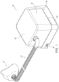
- a breathing assistance apparatus 20 is shown that is arranged and configured in accordance with certain features, aspects and advantages of the present invention.
- the breathing assistance apparatus 20 is connected to a conduit 22 and the conduit 22 is connected to a user interface 24, such as a breathing mask or the like. Any suitable user interface 24 can be used.
- the breathing assistance apparatus 20 is configured to deliver a flow of pressurized breathing gases to the user through the conduit 22 and the user interface 24.
- the illustrated breathing assistance apparatus 20 comprises a flow generator 26, which has been schematically illustrated in Figure 1 .
- the flow generator 26 can have any suitable construction.
- the flow generator 26 is a blower that draws ambient air into the breathing assistance apparatus 20 and generates the flow of pressurized breathing gases.
- the breathing assistance apparatus 20 also is configured to humidify the flow of pressurized breathing gases prior to deliver to the user.
- the illustrated breathing assistance apparatus 20 also comprises a humidification chamber 28.
- the humidification chamber 28 can be removable from the breathing assistance apparatus 20. Any suitable construction can be used for the humidification chamber 28.
- the humidification chamber 28 can be configured to contain a volume of liquid, such as water. The flow of pressurized breathing gases can pass over the volume of liquid en route to the user such that the flow of pressurized breathing gases can increase in humidity.
- the breathing assistance apparatus 20 generally comprises a main body 30.
- the main body 30 comprises an upper housing 32 and a lower housing 34.
- the upper housing 32 and the lower housing 34 can be secured together in any suitable manner.
- the bottom of the lower housing 34 is enclosed by a further cover.
- the lower housing 34 can include an air inlet 36 through which the flow generator 26 draws air.
- the flow generator 26 is mounted within the lower housing 34.
- the lower housing 34 also can support a heating element 38.
- the liquid within the humidification chamber 28 can be heated through an interaction with the heating element 38.
- the heating element 38 can be a heater plate and the humidification chamber 28 can rest on the heater plate. Other configurations are possible.
- the main body 30 comprises at least one outer wall 40.
- the main body 30 comprises four generally vertical outer walls 40.
- An upper portion of the at least one wall 40 generally defines an opening 42.
- the opening 42 can be closed with a lid 44.
- the lid 44 can seal the opening 42 in some configurations.
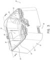
- the main body 30 contains a humidification compartment 50 that receives the humidification chamber 28.
- the humidification compartment 50 is generally defined within the at least one outer wall 40, the lid 44 and a base surface 46. More particularly, in the illustrated configuration, at least one generally vertical inner wall 52 defines at least a portion of the humidification compartment 50. Even more particularly, four generally vertical walls, including the at least one generally vertical inner wall 52, largely define the humidification compartment 50.
- a liquid containment compartment 54 is separated from the humidification compartment 50. In some configurations, the liquid containment compartment 54 limits the travel of liquid that may spill from the humidification chamber 28. In some configurations, the liquid containment compartment 54 can limit the travel of liquid that may be spilled within the humidification compartment 50 and outside of the humidification chamber 28.
- the liquid containment compartment 54 is positioned within the main body 30 of the breathing assistance apparatus 20. In the illustrated configuration, the liquid containment compartment 54 is integrated into the main body 30 of the breathing assistance apparatus 20. The liquid containment compartment 54 and the flow generator 26 are both integrated into the main body 30. The liquid containment compartment 54 is fluidly connected to the flow generator 26 and to the humidification compartment 50. The liquid containment compartment 54 is positioned between the flow generator 26 and the humidification compartment 54. The liquid containment compartment 54 is positioned between the outer wall 40 and the inner wall 52 of the main body. The inner wall 52 separates the humidification compartment 50 from the liquid containment compartment 54.
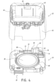
- the liquid containment compartment 54 includes two openings.
- a first opening 56 as shown in Figure 3 , extends through the inner wall 52.
- the first opening 56 defines a gas inlet for the humidification compartment 50 and a gas outlet for the liquid containment compartment 54. Gases flowing through the first opening 56 will be received by the humidification chamber 28 and will be humidified prior to delivery to the user. In other words, with the lid 44 in position and closed, the humidification chamber 28 is sealed in position within the humidification compartment 50. Gas passing through the first opening 56 will flow into the humidification compartment 50, and from the humidification compartment, the gases will flow into the humidification chamber 28 prior to passing out of the breathing assistance apparatus 20.
- a second opening 58 defines a gas inlet into the liquid containment compartment 54 and a gas outlet for flow from a passage 66 leading from the flow generator 26.
- the first opening 56 is in the upper housing 32 and the second opening 58 is in the lower housing 34.
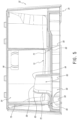
- the first opening 56 is offset both horizontally and vertically from the second opening.
- the first opening 56 is offset at least horizontally from the second opening 58, as shown in Figure 5 (i.e., the first opening 56 is to the right of the second opening 58).
- the first opening 56 is completely offset at least horizontally from the second opening 58.
- the two openings 56, 58 are offset in two orthogonal directions (e.g., horizontally and vertically). In some configurations, the two openings 56, 58 are offset in three orthogonal directions (horizontally in two orthogonal directions and vertically). Offset positioning of the first opening 56 relative to the second opening 58 reduces the likelihood of liquids spilling, draining, depositing or otherwise passing through the first opening 56 into the liquid containment compartment 54 passing further upstream toward the flow generator 26 relative to the liquid containment chamber 54. In other words, liquid is unlikely to easily pass through the first opening 56 and into the second opening 58. As such, liquid infiltration from the humidification chamber 28 toward the flow generator 26 can be inhibited.
- the liquid containment compartment 54 comprises at least a lower wall 70.
- the lower wall 70 is formed as part of the lower housing 34.
- a ridge 72 can be defined on a portion of the lower housing 34.
- the illustrated ridge 72 can generally encircle a reservoir 74.
- the ridge 72 generally surrounds the second opening 58.
- Other configurations are possible.
- the second opening 58 is vertically higher than the lower wall 70.
- the second opening 58 spans a vertical distance and the lowermost portion of the second opening 58 is vertically higher than the lower wall 70.
- the lower wall 70 can span a vertical distance (i.e., not be substantially flat) and the second opening 58 is vertically higher than any portion of the lower wall 70 that is directly adjacent to the second opening 58.
- the second opening 58 is formed atop of a pedestal 76.
- the pedestal 76 can be integrally formed with the lower housing 34.
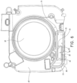
- the pedestal 76 generally encircles a passage 80 as shown in Figures 5 and 6 .
- the second opening 58 is generally canted such that the upper surface of the illustrated pedestal angles toward the first opening 56.
- at least an inner surface of the pedestal 76 that is furthest from the first opening 56 bends toward the first opening 56.
- the deflected portion of pedestal 76 that is generally adjacent the second opening 58 forms a lip 82.
- the lip 82 can help to deflect the gases flow toward the general direction of the first opening 56.
- the second opening 58 also has a narrowing region 84.
- the narrowing region 84 is disposed closest to the first opening 56 in the illustrated configuration. As shown in Figure 5 , the narrowing region 84 does not extend upward to the same extent as the lip region 82. The lip region 82 and/or the narrowing region 84 can help tailor and direct the gas flow in a desired manner. Other configurations are possible.
- At least a portion of the liquid containment compartment 54 is defined between the inner wall 52 and the outer wall 40 of the main body 30.
- at least a first wall 78 and, in some configurations, a second wall 84 can cooperate with the inner wall 52 and the outer wall 40 to define the sides of the liquid containment compartment 54.
- These walls 40, 52, 78, 84 can be integrally formed with the upper housing 32.
- the ridge 72 can match the configuration of these walls 40, 52, 78, 84. As such, the ridge 72 and these walls 40, 52, 78 and 84 can abut each other.
- a seal 86 can be positioned between the upper housing 32 and the lower housing 34. In the illustrated configuration, the seal 86 is positioned within a groove 90 (see Figure 5 ). The groove 90 may be positioned within the ridge 72.
- the seal 86 can be formed of a more resilient material than the ridge 72. As such, the seal 86 can deform upon contact with the walls 40, 52, 78, 84. The compression of the seal 86 can reduce the likelihood of liquid or gas leaks into or out of the liquid containment compartment 54.
- the seal 86 between the upper housing 32 and the lower housing 34 can reduce the likelihood of liquid migration even if the level of liquid within the liquid containment chamber 54 exceeds the height of the ridge 72.
Landscapes
- Health & Medical Sciences (AREA)
- Emergency Medicine (AREA)
- Pulmonology (AREA)
- Engineering & Computer Science (AREA)
- Anesthesiology (AREA)
- Biomedical Technology (AREA)
- Heart & Thoracic Surgery (AREA)
- Hematology (AREA)
- Life Sciences & Earth Sciences (AREA)
- Animal Behavior & Ethology (AREA)
- General Health & Medical Sciences (AREA)
- Public Health (AREA)
- Veterinary Medicine (AREA)
- Air Humidification (AREA)
- Respiratory Apparatuses And Protective Means (AREA)
- Devices For Medical Bathing And Washing (AREA)
Claims (13)
- Un appareil d'assistance respiratoire (20) comprenant un corps principal (30), le corps principal (30) comprenant un boîtier supérieur (32) et un boîtier inférieur (34) qui sont configurés pour être assujettis ensemble, un fond du boîtier inférieur (34) étant enfermé dans un capot, le boîtier supérieur (32) ayant au moins une paroi extérieure (40) et au moins une paroi intérieure généralement verticale (52), un compartiment d'humidification (50) défini à l'intérieur du corps principal (30) et apte à recevoir une chambre d'humidification (28), un générateur d'écoulement (26) monté à l'intérieur du boîtier inférieur (34), et un compartiment de rétention de liquide (54) positionné à l'intérieur du corps principal (30) entre l'au moins une paroi extérieure (40) et l'au moins une paroi intérieure généralement verticale (52), le compartiment de rétention de liquide (54) étant raccordé fluidiquement à la fois au générateur d'écoulement (26) et au compartiment d'humidification de manière à ce qu'un trajet d'écoulement de gaz du générateur d'écoulement (26) au compartiment d'humidification traverse le compartiment de rétention de liquide (54), et le compartiment de rétention de liquide (54) comprenant une surface inférieure qui fait partie d'une surface supérieure du boîtier inférieur (34), une première ouverture (56) dans le boîtier supérieur (32) qui définit une sortie pour l'écoulement des gaz hors du compartiment de rétention de liquide (54) vers le compartiment d'humidification, et une deuxième ouverture (58) dans le boîtier inférieur (34), la deuxième ouverture (58) étant positionnée généralement verticalement plus haut que la surface inférieure qui définit une entrée pour l'écoulement des gaz dans le compartiment de rétention de liquide (54) depuis le générateur d'écoulement (26).
- L'appareil d'assistance respiratoire (20) selon la revendication 1, dans lequel le compartiment de rétention de liquide (54) comprend une paroi verticale définissant les côtés du compartiment de rétention de liquide (54) qui fait partie du boîtier supérieur (32) du corps principal (30).
- L'appareil d'assistance respiratoire (20) selon la revendication 2, dans lequel une partie de la paroi verticale du compartiment de rétention de liquide (54) correspond à une partie d'une paroi verticale qui définit le compartiment d'humidification (50).
- L'appareil d'assistance respiratoire (20) selon la revendication 3, dans lequel la première ouverture (56) s'étend à travers la partie de la paroi verticale du compartiment de rétention de liquide (54) qui correspond à la paroi verticale du compartiment d'humidification (50).
- L'appareil d'assistance respiratoire (20) selon une quelconque des revendications 2 à 4, dans lequel une partie de la paroi verticale du compartiment de rétention de liquide (54) correspond à une partie d'une paroi extérieure du corps principal (30) fournie par le boîtier supérieur (32).
- L'appareil d'assistance respiratoire (20) selon une quelconque des revendications 2 à 5, dans lequel le compartiment de rétention de liquide (54) comprend une arête (72) qui définit la périphérie de la surface inférieure du compartiment de rétention de liquide (54) et qui s'étend à partir du boîtier inférieur du corps principal (30), l'arête (72) correspondant à la configuration de la paroi verticale du compartiment de rétention de liquide (54) fournie dans le boîtier supérieur (32) de manière à ce que l'arête (72) du boîtier inférieur (34) et la paroi verticale du boîtier supérieur (32) aboutent l'une à l'autre pour former le compartiment de rétention de liquide (54) quand le corps principal (30) est assemblé.
- L'appareil d'assistance respiratoire (20) selon la revendication 6, dans lequel l'arête (72) du compartiment de rétention de liquide (54) définit et encercle un réservoir du compartiment de rétention de liquide.
- L'appareil d'assistance respiratoire (20) selon la revendication 7, dans lequel l'arête (72) du compartiment de rétention de liquide (54) entoure la deuxième ouverture (58).
- L'appareil d'assistance respiratoire (20) selon une quelconque des revendications précédentes, dans lequel la première ouverture (56) et la deuxième ouverture (58) du compartiment de rétention de liquide (54) sont décalées l'une de l'autre dans au moins deux directions spatiales orthogonales.
- L'appareil d'assistance respiratoire (20) selon la revendication 9, dans lequel la première ouverture (56) et la deuxième ouverture (58) du compartiment de rétention de liquide (54) sont décalées horizontalement et verticalement ; et/ou dans lequel la première ouverture (56) et la deuxième ouverture (58) du compartiment de rétention de liquide (54) sont décalées l'une de l'autre dans trois directions spatiales orthogonales
- L'appareil d'assistance respiratoire (20) selon la revendication 10 dans lequel la première ouverture (56) et le la deuxième ouverture (58) du compartiment de rétention de liquide (54) sont décalées horizontalement dans deux directions spatiales orthogonales et verticalement.
- L'appareil d'assistance respiratoire (20) selon une quelconque des revendications 9 à 11, dans lequel aucune partie de la première ouverture (56) n'est alignée verticalement avec la deuxième ouverture (58) ; et/ou dans lequel aucune partie de la première ouverture (56) n'est alignée horizontalement avec la deuxième ouverture (58).
- L'appareil d'assistance respiratoire (20) selon une quelconque des revendications précédentes, dans lequel la deuxième ouverture (58) est raccordée fluidiquement au générateur d'écoulement (26) par un ou plusieurs passages à l'intérieur du corps principal (30) qui forment une partie du trajet d'écoulement des gaz.
Priority Applications (1)
| Application Number | Priority Date | Filing Date | Title |
|---|---|---|---|
| EP23165211.6A EP4218881A1 (fr) | 2014-01-30 | 2015-01-29 | Appareil d'assistance respiratoire avec confinement de liquide |
Applications Claiming Priority (3)
| Application Number | Priority Date | Filing Date | Title |
|---|---|---|---|
| US201461933775P | 2014-01-30 | 2014-01-30 | |
| PCT/NZ2015/050005 WO2015115916A1 (fr) | 2014-01-30 | 2015-01-29 | Appareil d'assistance respiratoire avec confinement de liquide |
| EP15743509.0A EP3099366B1 (fr) | 2014-01-30 | 2015-01-29 | Appareil d'assistance respiratoire avec confinement de liquide |
Related Parent Applications (2)
| Application Number | Title | Priority Date | Filing Date |
|---|---|---|---|
| EP15743509.0A Division-Into EP3099366B1 (fr) | 2014-01-30 | 2015-01-29 | Appareil d'assistance respiratoire avec confinement de liquide |
| EP15743509.0A Division EP3099366B1 (fr) | 2014-01-30 | 2015-01-29 | Appareil d'assistance respiratoire avec confinement de liquide |
Related Child Applications (2)
| Application Number | Title | Priority Date | Filing Date |
|---|---|---|---|
| EP23165211.6A Division EP4218881A1 (fr) | 2014-01-30 | 2015-01-29 | Appareil d'assistance respiratoire avec confinement de liquide |
| EP23165211.6A Division-Into EP4218881A1 (fr) | 2014-01-30 | 2015-01-29 | Appareil d'assistance respiratoire avec confinement de liquide |
Publications (2)
| Publication Number | Publication Date |
|---|---|
| EP3590571A1 EP3590571A1 (fr) | 2020-01-08 |
| EP3590571B1 true EP3590571B1 (fr) | 2023-05-10 |
Family
ID=53757394
Family Applications (3)
| Application Number | Title | Priority Date | Filing Date |
|---|---|---|---|
| EP23165211.6A Pending EP4218881A1 (fr) | 2014-01-30 | 2015-01-29 | Appareil d'assistance respiratoire avec confinement de liquide |
| EP19192027.1A Active EP3590571B1 (fr) | 2014-01-30 | 2015-01-29 | Appareil d'assistance respiratoire avec confinement de liquide |
| EP15743509.0A Active EP3099366B1 (fr) | 2014-01-30 | 2015-01-29 | Appareil d'assistance respiratoire avec confinement de liquide |
Family Applications Before (1)
| Application Number | Title | Priority Date | Filing Date |
|---|---|---|---|
| EP23165211.6A Pending EP4218881A1 (fr) | 2014-01-30 | 2015-01-29 | Appareil d'assistance respiratoire avec confinement de liquide |
Family Applications After (1)
| Application Number | Title | Priority Date | Filing Date |
|---|---|---|---|
| EP15743509.0A Active EP3099366B1 (fr) | 2014-01-30 | 2015-01-29 | Appareil d'assistance respiratoire avec confinement de liquide |
Country Status (10)
| Country | Link |
|---|---|
| US (3) | US10493229B2 (fr) |
| EP (3) | EP4218881A1 (fr) |
| JP (4) | JP6586097B2 (fr) |
| CN (2) | CN105939748B (fr) |
| AU (4) | AU2015211502B2 (fr) |
| BR (1) | BR112016016630B1 (fr) |
| CA (2) | CA3159009A1 (fr) |
| GB (2) | GB2541117B (fr) |
| SG (2) | SG10201907307SA (fr) |
| WO (1) | WO2015115916A1 (fr) |
Families Citing this family (5)
| Publication number | Priority date | Publication date | Assignee | Title |
|---|---|---|---|---|
| CA3159009A1 (fr) | 2014-01-30 | 2015-08-06 | Fisher & Paykel Healthcare Limited | Appareil d'assistance respiratoire avec confinement de liquide |
| USD790683S1 (en) * | 2015-03-11 | 2017-06-27 | Resmed Limited | Pressurized air delivery console |
| US11083866B2 (en) | 2016-07-01 | 2021-08-10 | Fisher & Paykel Healthcare Limited | Relating to a respiratory device |
| US10957966B2 (en) | 2018-02-06 | 2021-03-23 | Barkan Mounts Ltd | Wall mount for screens with an integrated antenna |
| CN114272487B (zh) * | 2021-12-27 | 2024-05-03 | 北京谊安健康科技有限公司 | 一种防止液体回流的湿化装置 |
Family Cites Families (27)
| Publication number | Priority date | Publication date | Assignee | Title |
|---|---|---|---|---|
| US4028444A (en) * | 1974-03-25 | 1977-06-07 | Chemetron Corporation | Humidifier and automatic control system therefor |
| US6398197B1 (en) | 1999-05-10 | 2002-06-04 | Fisher & Paykel Limited | Water chamber |
| US6935337B2 (en) | 2001-02-16 | 2005-08-30 | Resmed Limited | Humidifier with structure to prevent backflow of liquid through the humidifier inlet |
| DE10226160B4 (de) * | 2002-06-12 | 2009-06-18 | Hoffrichter Gmbh | Luftbefeuchter für ein Beatmungsgerät |
| US20030188746A1 (en) * | 2003-05-13 | 2003-10-09 | Roger Daugherty | Apparatus and method for humidification of inspired gases |
| AU2013201490B2 (en) * | 2003-06-20 | 2014-09-25 | ResMed Pty Ltd | Breathable Gas Apparatus with Humidifier |
| CA3146667A1 (en) * | 2003-06-20 | 2004-12-29 | ResMed Pty Ltd | Breathable gas apparatus with humidifier |
| AU2003903139A0 (en) * | 2003-06-20 | 2003-07-03 | Resmed Limited | Breathable gas apparatus with humidifier |
| CN2695846Y (zh) * | 2003-08-07 | 2005-04-27 | 北京杰富瑞科技有限公司 | 防反流加温湿化装置 |
| CA2535974C (fr) * | 2003-08-20 | 2011-10-18 | Fisher & Paykel Healthcare Limited | Chambre d'equilibre pour humidificateur |
| CN102133447B (zh) * | 2005-08-15 | 2015-01-07 | 瑞思迈有限公司 | 用于cpap装置的加湿器和/或气流发生器 |
| US8701662B2 (en) * | 2005-09-27 | 2014-04-22 | Ric Investments, Llc | Humidifier with back-flow prevention valve |
| CN101516430B (zh) | 2006-08-25 | 2011-11-02 | 菲舍尔和佩克尔保健有限公司 | 具有内部加热元件的加湿器 |
| CA3200535A1 (fr) * | 2006-11-06 | 2008-05-15 | Fisher & Paykel Healthcare Limited | Chambre et couvercle d'humidificateur integres |
| US8905023B2 (en) * | 2007-10-05 | 2014-12-09 | Vapotherm, Inc. | Hyperthermic humidification system |
| JP5785076B2 (ja) * | 2008-06-27 | 2015-09-24 | コーニンクレッカ フィリップス エヌ ヴェ | 呼吸システム用加湿器 |
| NZ590924A (en) * | 2008-09-17 | 2013-08-30 | Resmed Ltd | Humidification of respiratory gases |
| KR101532576B1 (ko) * | 2008-11-28 | 2015-06-30 | 엘지전자 주식회사 | 가습기 |
| CA2764382C (fr) * | 2009-06-05 | 2017-03-21 | Fisher & Paykel Healthcare Limited | Base d'humidificateur chauffant |
| WO2011078706A2 (fr) * | 2009-12-23 | 2011-06-30 | Fisher & Paykel Healthcare Limited | Dispositif de distribution de gaz humidifiés et procédés de commande de celui-ci |
| JP6002696B2 (ja) * | 2011-03-14 | 2016-10-05 | コーニンクレッカ フィリップス エヌ ヴェKoninklijke Philips N.V. | 液体侵入保護を備える加湿器 |
| CN103442760B (zh) * | 2011-04-05 | 2016-10-26 | 瑞思迈有限公司 | 呼吸设备 |
| DE11005292T1 (de) * | 2011-06-29 | 2013-07-25 | Healthc'air | Behälter für Gerät zur Atmungsunterstützung |
| US10213573B2 (en) * | 2011-12-22 | 2019-02-26 | Resmed Limited | Humidifiers for respiratory apparatus |
| US10317098B2 (en) * | 2012-03-15 | 2019-06-11 | ResMed Pty Ltd | Heating apparatus |
| CN202654514U (zh) * | 2012-05-22 | 2013-01-09 | 北京怡和嘉业医疗科技有限公司 | 加湿设备和具有该加湿设备的通气治疗设备 |
| CA3159009A1 (fr) | 2014-01-30 | 2015-08-06 | Fisher & Paykel Healthcare Limited | Appareil d'assistance respiratoire avec confinement de liquide |
-
2015
- 2015-01-29 CA CA3159009A patent/CA3159009A1/fr active Pending
- 2015-01-29 US US15/113,787 patent/US10493229B2/en active Active
- 2015-01-29 CA CA2936923A patent/CA2936923C/fr active Active
- 2015-01-29 AU AU2015211502A patent/AU2015211502B2/en active Active
- 2015-01-29 WO PCT/NZ2015/050005 patent/WO2015115916A1/fr active Application Filing
- 2015-01-29 SG SG10201907307SA patent/SG10201907307SA/en unknown
- 2015-01-29 JP JP2016549441A patent/JP6586097B2/ja active Active
- 2015-01-29 SG SG11201605793SA patent/SG11201605793SA/en unknown
- 2015-01-29 GB GB1612153.5A patent/GB2541117B/en active Active
- 2015-01-29 EP EP23165211.6A patent/EP4218881A1/fr active Pending
- 2015-01-29 EP EP19192027.1A patent/EP3590571B1/fr active Active
- 2015-01-29 CN CN201580006405.9A patent/CN105939748B/zh active Active
- 2015-01-29 CN CN201911341572.5A patent/CN111068157B/zh active Active
- 2015-01-29 BR BR112016016630-2A patent/BR112016016630B1/pt active IP Right Grant
- 2015-01-29 GB GB1805636.6A patent/GB2559901B/en active Active
- 2015-01-29 EP EP15743509.0A patent/EP3099366B1/fr active Active
-
2019
- 2019-09-06 JP JP2019162901A patent/JP6974406B2/ja active Active
- 2019-10-30 US US16/668,764 patent/US11305090B2/en active Active
-
2020
- 2020-04-08 AU AU2020202424A patent/AU2020202424B2/en active Active
-
2021
- 2021-11-04 JP JP2021180027A patent/JP2022016476A/ja active Pending
- 2021-11-25 AU AU2021273596A patent/AU2021273596B2/en active Active
-
2022
- 2022-03-15 US US17/654,894 patent/US20220280745A1/en active Pending
-
2023
- 2023-12-04 AU AU2023274229A patent/AU2023274229A1/en active Pending
- 2023-12-25 JP JP2023218243A patent/JP2024028308A/ja active Pending
Also Published As
Similar Documents
| Publication | Publication Date | Title |
|---|---|---|
| US11305090B2 (en) | Breathing assistance apparatus with liquid containment | |
| EP2686053B1 (fr) | Humidificateur équipé d'une protection contre l'entrée d'un liquide | |
| US5943473A (en) | Heated cartridge humidifier | |
| JP2005538817A (ja) | 加湿器用水充填装置 | |
| US20180078729A1 (en) | Vapor delivery system | |
| ES2783978T3 (es) | Depósito de agua mejorado para un humidificador de gas calefactor alimentado por un ventilador médico | |
| EP2842589A2 (fr) | Humidificateur pour appareil respiratoire | |
| US20170336086A1 (en) | Liquid container for gas humidification and gas humidification method | |
| EP4294487B1 (fr) | Protection intégrée d'entrée d'eau d'humidificateur |
Legal Events
| Date | Code | Title | Description |
|---|---|---|---|
| PUAI | Public reference made under article 153(3) epc to a published international application that has entered the european phase |
Free format text: ORIGINAL CODE: 0009012 |
|
| STAA | Information on the status of an ep patent application or granted ep patent |
Free format text: STATUS: THE APPLICATION HAS BEEN PUBLISHED |
|
| AC | Divisional application: reference to earlier application |
Ref document number: 3099366 Country of ref document: EP Kind code of ref document: P |
|
| AK | Designated contracting states |
Kind code of ref document: A1 Designated state(s): AL AT BE BG CH CY CZ DE DK EE ES FI FR GB GR HR HU IE IS IT LI LT LU LV MC MK MT NL NO PL PT RO RS SE SI SK SM TR |
|
| STAA | Information on the status of an ep patent application or granted ep patent |
Free format text: STATUS: REQUEST FOR EXAMINATION WAS MADE |
|
| 17P | Request for examination filed |
Effective date: 20200708 |
|
| RBV | Designated contracting states (corrected) |
Designated state(s): AL AT BE BG CH CY CZ DE DK EE ES FI FR GB GR HR HU IE IS IT LI LT LU LV MC MK MT NL NO PL PT RO RS SE SI SK SM TR |
|
| STAA | Information on the status of an ep patent application or granted ep patent |
Free format text: STATUS: EXAMINATION IS IN PROGRESS |
|
| 17Q | First examination report despatched |
Effective date: 20210531 |
|
| GRAP | Despatch of communication of intention to grant a patent |
Free format text: ORIGINAL CODE: EPIDOSNIGR1 |
|
| STAA | Information on the status of an ep patent application or granted ep patent |
Free format text: STATUS: GRANT OF PATENT IS INTENDED |
|
| INTG | Intention to grant announced |
Effective date: 20220713 |
|
| RAP3 | Party data changed (applicant data changed or rights of an application transferred) |
Owner name: FISHER & PAYKEL HEALTHCARE LIMITED |
|
| GRAJ | Information related to disapproval of communication of intention to grant by the applicant or resumption of examination proceedings by the epo deleted |
Free format text: ORIGINAL CODE: EPIDOSDIGR1 |
|
| STAA | Information on the status of an ep patent application or granted ep patent |
Free format text: STATUS: EXAMINATION IS IN PROGRESS |
|
| GRAP | Despatch of communication of intention to grant a patent |
Free format text: ORIGINAL CODE: EPIDOSNIGR1 |
|
| STAA | Information on the status of an ep patent application or granted ep patent |
Free format text: STATUS: GRANT OF PATENT IS INTENDED |
|
| INTC | Intention to grant announced (deleted) | ||
| INTG | Intention to grant announced |
Effective date: 20221209 |
|
| RAP3 | Party data changed (applicant data changed or rights of an application transferred) |
Owner name: FISHER & PAYKEL HEALTHCARE LIMITED |
|
| RIN1 | Information on inventor provided before grant (corrected) |
Inventor name: SUN, YI-CHENG |
|
| GRAS | Grant fee paid |
Free format text: ORIGINAL CODE: EPIDOSNIGR3 |
|
| GRAA | (expected) grant |
Free format text: ORIGINAL CODE: 0009210 |
|
| STAA | Information on the status of an ep patent application or granted ep patent |
Free format text: STATUS: THE PATENT HAS BEEN GRANTED |
|
| AC | Divisional application: reference to earlier application |
Ref document number: 3099366 Country of ref document: EP Kind code of ref document: P |
|
| AK | Designated contracting states |
Kind code of ref document: B1 Designated state(s): AL AT BE BG CH CY CZ DE DK EE ES FI FR GB GR HR HU IE IS IT LI LT LU LV MC MK MT NL NO PL PT RO RS SE SI SK SM TR |
|
| REG | Reference to a national code |
Ref country code: GB Ref legal event code: FG4D |
|
| REG | Reference to a national code |
Ref country code: AT Ref legal event code: REF Ref document number: 1566104 Country of ref document: AT Kind code of ref document: T Effective date: 20230515 Ref country code: CH Ref legal event code: EP |
|
| REG | Reference to a national code |
Ref country code: DE Ref legal event code: R096 Ref document number: 602015083582 Country of ref document: DE |
|
| REG | Reference to a national code |
Ref country code: IE Ref legal event code: FG4D |
|
| P01 | Opt-out of the competence of the unified patent court (upc) registered |
Effective date: 20230526 |
|
| REG | Reference to a national code |
Ref country code: LT Ref legal event code: MG9D |
|
| REG | Reference to a national code |
Ref country code: NL Ref legal event code: MP Effective date: 20230510 |
|
| REG | Reference to a national code |
Ref country code: AT Ref legal event code: MK05 Ref document number: 1566104 Country of ref document: AT Kind code of ref document: T Effective date: 20230510 |
|
| PG25 | Lapsed in a contracting state [announced via postgrant information from national office to epo] |
Ref country code: SE Free format text: LAPSE BECAUSE OF FAILURE TO SUBMIT A TRANSLATION OF THE DESCRIPTION OR TO PAY THE FEE WITHIN THE PRESCRIBED TIME-LIMIT Effective date: 20230510 Ref country code: PT Free format text: LAPSE BECAUSE OF FAILURE TO SUBMIT A TRANSLATION OF THE DESCRIPTION OR TO PAY THE FEE WITHIN THE PRESCRIBED TIME-LIMIT Effective date: 20230911 Ref country code: NO Free format text: LAPSE BECAUSE OF FAILURE TO SUBMIT A TRANSLATION OF THE DESCRIPTION OR TO PAY THE FEE WITHIN THE PRESCRIBED TIME-LIMIT Effective date: 20230810 Ref country code: NL Free format text: LAPSE BECAUSE OF FAILURE TO SUBMIT A TRANSLATION OF THE DESCRIPTION OR TO PAY THE FEE WITHIN THE PRESCRIBED TIME-LIMIT Effective date: 20230510 Ref country code: ES Free format text: LAPSE BECAUSE OF FAILURE TO SUBMIT A TRANSLATION OF THE DESCRIPTION OR TO PAY THE FEE WITHIN THE PRESCRIBED TIME-LIMIT Effective date: 20230510 Ref country code: AT Free format text: LAPSE BECAUSE OF FAILURE TO SUBMIT A TRANSLATION OF THE DESCRIPTION OR TO PAY THE FEE WITHIN THE PRESCRIBED TIME-LIMIT Effective date: 20230510 |
|
| PG25 | Lapsed in a contracting state [announced via postgrant information from national office to epo] |
Ref country code: RS Free format text: LAPSE BECAUSE OF FAILURE TO SUBMIT A TRANSLATION OF THE DESCRIPTION OR TO PAY THE FEE WITHIN THE PRESCRIBED TIME-LIMIT Effective date: 20230510 Ref country code: PL Free format text: LAPSE BECAUSE OF FAILURE TO SUBMIT A TRANSLATION OF THE DESCRIPTION OR TO PAY THE FEE WITHIN THE PRESCRIBED TIME-LIMIT Effective date: 20230510 Ref country code: LV Free format text: LAPSE BECAUSE OF FAILURE TO SUBMIT A TRANSLATION OF THE DESCRIPTION OR TO PAY THE FEE WITHIN THE PRESCRIBED TIME-LIMIT Effective date: 20230510 Ref country code: LT Free format text: LAPSE BECAUSE OF FAILURE TO SUBMIT A TRANSLATION OF THE DESCRIPTION OR TO PAY THE FEE WITHIN THE PRESCRIBED TIME-LIMIT Effective date: 20230510 Ref country code: IS Free format text: LAPSE BECAUSE OF FAILURE TO SUBMIT A TRANSLATION OF THE DESCRIPTION OR TO PAY THE FEE WITHIN THE PRESCRIBED TIME-LIMIT Effective date: 20230910 Ref country code: HR Free format text: LAPSE BECAUSE OF FAILURE TO SUBMIT A TRANSLATION OF THE DESCRIPTION OR TO PAY THE FEE WITHIN THE PRESCRIBED TIME-LIMIT Effective date: 20230510 Ref country code: GR Free format text: LAPSE BECAUSE OF FAILURE TO SUBMIT A TRANSLATION OF THE DESCRIPTION OR TO PAY THE FEE WITHIN THE PRESCRIBED TIME-LIMIT Effective date: 20230811 |
|
| PG25 | Lapsed in a contracting state [announced via postgrant information from national office to epo] |
Ref country code: FI Free format text: LAPSE BECAUSE OF FAILURE TO SUBMIT A TRANSLATION OF THE DESCRIPTION OR TO PAY THE FEE WITHIN THE PRESCRIBED TIME-LIMIT Effective date: 20230510 |
|
| PG25 | Lapsed in a contracting state [announced via postgrant information from national office to epo] |
Ref country code: SK Free format text: LAPSE BECAUSE OF FAILURE TO SUBMIT A TRANSLATION OF THE DESCRIPTION OR TO PAY THE FEE WITHIN THE PRESCRIBED TIME-LIMIT Effective date: 20230510 |
|
| PGFP | Annual fee paid to national office [announced via postgrant information from national office to epo] |
Ref country code: GB Payment date: 20231219 Year of fee payment: 10 |
|
| PG25 | Lapsed in a contracting state [announced via postgrant information from national office to epo] |
Ref country code: SM Free format text: LAPSE BECAUSE OF FAILURE TO SUBMIT A TRANSLATION OF THE DESCRIPTION OR TO PAY THE FEE WITHIN THE PRESCRIBED TIME-LIMIT Effective date: 20230510 Ref country code: SK Free format text: LAPSE BECAUSE OF FAILURE TO SUBMIT A TRANSLATION OF THE DESCRIPTION OR TO PAY THE FEE WITHIN THE PRESCRIBED TIME-LIMIT Effective date: 20230510 Ref country code: RO Free format text: LAPSE BECAUSE OF FAILURE TO SUBMIT A TRANSLATION OF THE DESCRIPTION OR TO PAY THE FEE WITHIN THE PRESCRIBED TIME-LIMIT Effective date: 20230510 Ref country code: EE Free format text: LAPSE BECAUSE OF FAILURE TO SUBMIT A TRANSLATION OF THE DESCRIPTION OR TO PAY THE FEE WITHIN THE PRESCRIBED TIME-LIMIT Effective date: 20230510 Ref country code: DK Free format text: LAPSE BECAUSE OF FAILURE TO SUBMIT A TRANSLATION OF THE DESCRIPTION OR TO PAY THE FEE WITHIN THE PRESCRIBED TIME-LIMIT Effective date: 20230510 Ref country code: CZ Free format text: LAPSE BECAUSE OF FAILURE TO SUBMIT A TRANSLATION OF THE DESCRIPTION OR TO PAY THE FEE WITHIN THE PRESCRIBED TIME-LIMIT Effective date: 20230510 |
|
| PGFP | Annual fee paid to national office [announced via postgrant information from national office to epo] |
Ref country code: FR Payment date: 20231219 Year of fee payment: 10 |
|
| REG | Reference to a national code |
Ref country code: DE Ref legal event code: R097 Ref document number: 602015083582 Country of ref document: DE |
|
| PLBE | No opposition filed within time limit |
Free format text: ORIGINAL CODE: 0009261 |
|
| STAA | Information on the status of an ep patent application or granted ep patent |
Free format text: STATUS: NO OPPOSITION FILED WITHIN TIME LIMIT |
|
| 26N | No opposition filed |
Effective date: 20240213 |
|
| PGFP | Annual fee paid to national office [announced via postgrant information from national office to epo] |
Ref country code: DE Payment date: 20231219 Year of fee payment: 10 |
|
| PG25 | Lapsed in a contracting state [announced via postgrant information from national office to epo] |
Ref country code: SI Free format text: LAPSE BECAUSE OF FAILURE TO SUBMIT A TRANSLATION OF THE DESCRIPTION OR TO PAY THE FEE WITHIN THE PRESCRIBED TIME-LIMIT Effective date: 20230510 |
|
| PG25 | Lapsed in a contracting state [announced via postgrant information from national office to epo] |
Ref country code: SI Free format text: LAPSE BECAUSE OF FAILURE TO SUBMIT A TRANSLATION OF THE DESCRIPTION OR TO PAY THE FEE WITHIN THE PRESCRIBED TIME-LIMIT Effective date: 20230510 Ref country code: IT Free format text: LAPSE BECAUSE OF FAILURE TO SUBMIT A TRANSLATION OF THE DESCRIPTION OR TO PAY THE FEE WITHIN THE PRESCRIBED TIME-LIMIT Effective date: 20230510 |
|
| PG25 | Lapsed in a contracting state [announced via postgrant information from national office to epo] |
Ref country code: MC Free format text: LAPSE BECAUSE OF FAILURE TO SUBMIT A TRANSLATION OF THE DESCRIPTION OR TO PAY THE FEE WITHIN THE PRESCRIBED TIME-LIMIT Effective date: 20230510 |
|
| PG25 | Lapsed in a contracting state [announced via postgrant information from national office to epo] |
Ref country code: MC Free format text: LAPSE BECAUSE OF FAILURE TO SUBMIT A TRANSLATION OF THE DESCRIPTION OR TO PAY THE FEE WITHIN THE PRESCRIBED TIME-LIMIT Effective date: 20230510 |
|
| REG | Reference to a national code |
Ref country code: CH Ref legal event code: PL |
|
| PG25 | Lapsed in a contracting state [announced via postgrant information from national office to epo] |
Ref country code: LU Free format text: LAPSE BECAUSE OF NON-PAYMENT OF DUE FEES Effective date: 20240129 |
|
| PG25 | Lapsed in a contracting state [announced via postgrant information from national office to epo] |
Ref country code: LU Free format text: LAPSE BECAUSE OF NON-PAYMENT OF DUE FEES Effective date: 20240129 |