EP3590391A1 - Vehicle seat cushion core - Google Patents
Vehicle seat cushion core Download PDFInfo
- Publication number
- EP3590391A1 EP3590391A1 EP18761896.2A EP18761896A EP3590391A1 EP 3590391 A1 EP3590391 A1 EP 3590391A1 EP 18761896 A EP18761896 A EP 18761896A EP 3590391 A1 EP3590391 A1 EP 3590391A1
- Authority
- EP
- European Patent Office
- Prior art keywords
- frame member
- molded article
- expanded beads
- beads molded
- slit
- Prior art date
- Legal status (The legal status is an assumption and is not a legal conclusion. Google has not performed a legal analysis and makes no representation as to the accuracy of the status listed.)
- Granted
Links
Images


Classifications
-
- B—PERFORMING OPERATIONS; TRANSPORTING
- B60—VEHICLES IN GENERAL
- B60N—SEATS SPECIALLY ADAPTED FOR VEHICLES; VEHICLE PASSENGER ACCOMMODATION NOT OTHERWISE PROVIDED FOR
- B60N2/00—Seats specially adapted for vehicles; Arrangement or mounting of seats in vehicles
- B60N2/005—Arrangement or mounting of seats in vehicles, e.g. dismountable auxiliary seats
- B60N2/015—Attaching seats directly to vehicle chassis
-
- A—HUMAN NECESSITIES
- A47—FURNITURE; DOMESTIC ARTICLES OR APPLIANCES; COFFEE MILLS; SPICE MILLS; SUCTION CLEANERS IN GENERAL
- A47C—CHAIRS; SOFAS; BEDS
- A47C27/00—Spring, stuffed or fluid mattresses or cushions specially adapted for chairs, beds or sofas
- A47C27/14—Spring, stuffed or fluid mattresses or cushions specially adapted for chairs, beds or sofas with foamed material inlays
- A47C27/142—Spring, stuffed or fluid mattresses or cushions specially adapted for chairs, beds or sofas with foamed material inlays with projections, depressions or cavities
-
- B—PERFORMING OPERATIONS; TRANSPORTING
- B60—VEHICLES IN GENERAL
- B60N—SEATS SPECIALLY ADAPTED FOR VEHICLES; VEHICLE PASSENGER ACCOMMODATION NOT OTHERWISE PROVIDED FOR
- B60N2/00—Seats specially adapted for vehicles; Arrangement or mounting of seats in vehicles
- B60N2/90—Details or parts not otherwise provided for
-
- A—HUMAN NECESSITIES
- A47—FURNITURE; DOMESTIC ARTICLES OR APPLIANCES; COFFEE MILLS; SPICE MILLS; SUCTION CLEANERS IN GENERAL
- A47C—CHAIRS; SOFAS; BEDS
- A47C27/00—Spring, stuffed or fluid mattresses or cushions specially adapted for chairs, beds or sofas
- A47C27/14—Spring, stuffed or fluid mattresses or cushions specially adapted for chairs, beds or sofas with foamed material inlays
-
- A—HUMAN NECESSITIES
- A47—FURNITURE; DOMESTIC ARTICLES OR APPLIANCES; COFFEE MILLS; SPICE MILLS; SUCTION CLEANERS IN GENERAL
- A47C—CHAIRS; SOFAS; BEDS
- A47C7/00—Parts, details, or accessories of chairs or stools
- A47C7/02—Seat parts
- A47C7/18—Seat parts having foamed material included in cushioning part
-
- A—HUMAN NECESSITIES
- A47—FURNITURE; DOMESTIC ARTICLES OR APPLIANCES; COFFEE MILLS; SPICE MILLS; SUCTION CLEANERS IN GENERAL
- A47C—CHAIRS; SOFAS; BEDS
- A47C7/00—Parts, details, or accessories of chairs or stools
- A47C7/02—Seat parts
- A47C7/18—Seat parts having foamed material included in cushioning part
- A47C7/20—Seat parts having foamed material included in cushioning part with reinforcement in the foam layer
-
- B—PERFORMING OPERATIONS; TRANSPORTING
- B60—VEHICLES IN GENERAL
- B60N—SEATS SPECIALLY ADAPTED FOR VEHICLES; VEHICLE PASSENGER ACCOMMODATION NOT OTHERWISE PROVIDED FOR
- B60N2/00—Seats specially adapted for vehicles; Arrangement or mounting of seats in vehicles
- B60N2/24—Seats specially adapted for vehicles; Arrangement or mounting of seats in vehicles for particular purposes or particular vehicles
- B60N2/42—Seats specially adapted for vehicles; Arrangement or mounting of seats in vehicles for particular purposes or particular vehicles the seat constructed to protect the occupant from the effect of abnormal g-forces, e.g. crash or safety seats
- B60N2/4249—Seats specially adapted for vehicles; Arrangement or mounting of seats in vehicles for particular purposes or particular vehicles the seat constructed to protect the occupant from the effect of abnormal g-forces, e.g. crash or safety seats fixed structures, i.e. where neither the seat nor a part thereof are displaced during a crash
- B60N2/4256—Seats specially adapted for vehicles; Arrangement or mounting of seats in vehicles for particular purposes or particular vehicles the seat constructed to protect the occupant from the effect of abnormal g-forces, e.g. crash or safety seats fixed structures, i.e. where neither the seat nor a part thereof are displaced during a crash the shape of the seat being specially adapted for a particular purpose or for particular vehicles
- B60N2/4263—Seats specially adapted for vehicles; Arrangement or mounting of seats in vehicles for particular purposes or particular vehicles the seat constructed to protect the occupant from the effect of abnormal g-forces, e.g. crash or safety seats fixed structures, i.e. where neither the seat nor a part thereof are displaced during a crash the shape of the seat being specially adapted for a particular purpose or for particular vehicles with anti-submarining systems
-
- B—PERFORMING OPERATIONS; TRANSPORTING
- B60—VEHICLES IN GENERAL
- B60N—SEATS SPECIALLY ADAPTED FOR VEHICLES; VEHICLE PASSENGER ACCOMMODATION NOT OTHERWISE PROVIDED FOR
- B60N2/00—Seats specially adapted for vehicles; Arrangement or mounting of seats in vehicles
- B60N2/70—Upholstery springs ; Upholstery
- B60N2/7017—Upholstery springs ; Upholstery characterised by the manufacturing process; manufacturing upholstery or upholstery springs not otherwise provided for
Definitions
- the present invention relates to a core material of a seat cushion for a vehicle, which is made of a thermoplastic resin expanded beads molded article in which a frame member is buried.
- a core material of a seat cushion for a vehicle a core material of a seat cushion for a vehicle in which a frame member made of metal and the like is buried in and integrated into a thermoplastic resin expanded beads molded article (hereinafter sometimes simply referred to as "expanded beads molded article") is used.
- the frame member buried in the expanded beads molded article functions as a structural frame for attaching to a vehicle body, a structural frame for seat arrangement, a reinforcing material during collision, or the like.
- a member formed by integrating such an expanded beads molded article and a frame member is composed of a base foam resin layer and the frame member disposed inside the base foam resin layer, and a composite expanded beads molded article has been proposed in which a foam layer of a foamable resin covered with the frame member and the base foam resin layer are engaged or engaged/fused to each other (see, for example, Patent Literature 1).
- Such a composite expanded beads molded article is manufactured, for example, by so-called insert molding, in which the frame member is disposed at a predetermined position in a mold, and then the expanded beads constituting the base is filled in the mold, heated, and fused.
- Patent Literature 1 JP-A-H05(1993)-154929
- the expanded beads molded article generally undergoes molding shrinkage after in-mold molding by a mold.
- warping may occur after in-mold molding due to a difference in shrinkage ratio between the expanded beads molded article and the frame member.
- the composite expanded beads molded article in which such warping remains is used as the core material of a seat cushion for a vehicle, there is a risk that the precision of attachment to the vehicle body is deteriorated or a predetermined performance cannot be secured.
- the shrinkage ratio of the expanded beads molded article after molding also differs depending on the type of thermoplastic resin expanded beads to be used, the manufacturing conditions, the material of the frame member, and the like, and is influenced by the shape of the expanded beads molded article and the arrangement state of the inserted frame member, it is difficult to accurately predict the degree of warping of the expanded beads molded article each time.
- Such a problem is remarkable particularly in the case of manufacturing a composite expanded beads molded article having a complicated shape in which the thick portions are formed on a foreside and both sides in order to prevent an occupant from slipping off and the like.
- An object of the present invention is to provide a core material of a seat cushion for a vehicle, which is made of a thermoplastic resin expanded beads molded article into which a frame member is integrated by insert molding, which has less warping and excellent dimensional precision.
- the present invention is a core material of a seat cushion for a vehicle described in the following [1] to [4].
- the core material of a seat cushion for a vehicle of the present invention since the first slit along the frame member is formed, and the second slit intersecting the frame member is formed, warping due to the difference in the shrinkage ratio between the expanded beads molded article and the frame member is relieved by the presence of the first slit and the second slit, a core material of a seat cushion for a vehicle which has less warping and excellent dimensional precision can be provided.
- the core material of a seat cushion for a vehicle which is a core material for a vehicle including: a thermoplastic resin expanded beads molded article having a substantially rectangular shape in a top view; and an annular frame member buried in the circumferential portion of the thermoplastic resin expanded beads molded article by insert molding.
- the expanded beads molded article includes: thick portions on a front side and on both sides of the expanded beads molded article; and an occupant seating portion on an upper surface in an inner region with respect to the circumferential portion.
- the frame member includes: a front frame portion; a rear frame portion; and two side frame portions connecting the front frame portion and the rear frame portion to each other.
- first slits are formed, the first slits each having a slit piece along the front frame member at a position in front of the occupant seating portion and inside the front frame portion and another slit piece along the side frame portion at a position between outside of the occupant seating portion and inside of the side frame portion; and at least one second slit intersecting the frame member is formed at a position in the thick portions where the frame member is buried.
- the "thermoplastic resin expanded beads molded article” is also simply referred to as an “expanded beads molded article”.
- the thermoplastic resin constituting the expanded beads molded article can be appropriately selected.
- the present invention can be suitably applied to the case where a polystyrene resin; a polyolefin resin such as polyethylene or polypropylene; a polyester resin such as polyethylene terephthalate or polylactic acid; or a composite resin of a polystyrene resin and a polyolefin resin may be used.
- a resin containing a polyolefin resin which is a crystalline resin is easy to shrink, the effect of the present invention for preventing warping can be remarkably exhibited when the polyolefin resin is used.
- thermoplastic resin expanded beads molded article in which the frame member is integrated by insert molding can be produced by a known method.
- a dispersing medium usually water
- a surfactant is added to a pressurizable closed container such as an autoclave, and the above-described thermoplastic resin particles are dispersed therein, the foaming agent is injected, and the mixture is stirred under heating to impregnate the resin particles with the foaming agent. Then, the resin particles impregnated with the foaming agent are discharged from the inside of the container which is under high temperature and high pressure together with the dispersion medium to a low-pressure region (usually at atmospheric pressure) to manufacture expanded beads foamed at a predetermined magnification.
- a low-pressure region usually at atmospheric pressure
- a mold in which the frame member is arranged in a predetermined position in advance is filled with the expanded beads, and in-mold molding is performed by introducing steam to fuse the expanded beads, the frame member and the expanded beads are integrated, thus the expanded beads molded article in which the frame member is buried can be manufactured as an integral molded article.
- the frame member used in the present invention is not particularly limited as long as the frame member is used as a frame member of the core material of a seat cushion for a vehicle.
- Examples thereof include: metal frame members made of iron, aluminum, copper, and the like; resin frame members made of an engineering plastic, a glass fiber reinforced resin, and the like, and these may be appropriately combined.
- the shape of the frame member is not particularly limited as long as the frame member functions as reinforcement during collision or attachment to the vehicle body, but is at least an annular shape that can be disposed at the circumferential portion of the thermoplastic resin expanded beads molded article. In a case of the annular frame member, one may have frame members having different rigidities connected to each other.
- the front side where the highest strength is required may be formed of a frame member having a high rigidity, and both sides and the rear side may be formed of linear frame members thinner than the front side, or may be formed by interposing a different material in a part thereof.
- the frame member is an annular reinforcing member having a substantially quadrangular shape in top view, the shape of the front side half and the shape of the rear side half may be different.
- the annular frame member 3 When normally used as a sheet for a vehicle, as shown in Fig. 2 , it is preferable to use the annular frame member 3 formed in a substantially rectangular shape which suits for the outer peripheral shape of the expanded beads molded article 2 so as to reinforce each side and four corners of the core material 1 for a seat cushion for a vehicle when viewed from above. Further, the entire periphery of the annular frame member 3 is not necessarily buried in the expanded beads molded article, and for example, a part of the frame member 3 may be exposed from the expanded beads molded article 2 in order to attach the frame member 3 to the vehicle body or to attach other members to the core material of a seat cushion for a vehicle.
- the frame member 3 has a substantially quadrangular annular shape, and has a front-rear asymmetric shape having different shapes between the front side half and the rear side half.
- the frame member 3 includes a linear front frame portion 3a having a thickness of approximately 4.5 mm, a frame portion 3b having a C shape in a plan view and a thickness of approximately 4.5 mm, and plate portions 3c connecting the front frame portion 3a and the frame portion 3b.
- the frame portion 3b includes a rear frame portion 3b-1 corresponding to a rear direction of the vehicle in a state in which the core material of a seat cushion for a vehicle is attached, and two side frame portions 3b-2 that connect the front frame portion and the rear frame portion to each other.
- a metal hook 3d for attaching to the vehicle is joined to each of the plate portions 3c, and two metal hooks 3e for connecting to the back sheet are joined to the C-shaped wire member 3b. The number of these hooks is not particularly limited.
- the thermoplastic resin expanded beads molded article 2 is formed in a generally rectangular shape in a top view.
- the thermoplastic resin expanded beads molded article 2 includes thick portions 4a, 4b on a front side portion 2a and both side portions 2b of the circumferential portion.
- the size of the thermoplastic resin expanded beads molded article 2 is appropriately designed according to the vehicle to be mounted, but the length in the long side direction is generally about 1000 mm to 1400 mm, and the length in the short side direction is generally about 400 mm to 600 mm.
- recessed portions 6, 6 are formed in which the thickness of the portions serving as two occupant seating portions is reduced in the long side direction.
- the thickness of the thermoplastic resin expanded beads molded article at the position of the recessed portion 6 serving as the occupant seating portion is preferably 15 mm to 40 mm, and more preferably 20 mm to 35 mm.
- the difference between the thickness of the thermoplastic resin expanded beads molded article at the position of the recessed portion 6 serving as the occupant seating portion and the thickness of the thermoplastic resin expanded beads molded article in the thick portion 4a of the front side portion 2a is preferably 60 mm to 165 mm, and more preferably 85 mm to 140 mm for preventing the occupant slipping off.
- the thickness of the thermoplastic resin expanded beads molded article in the thick portions 4a, 4b existing in the front side portion 2a and the side portions 2b, 2b is preferably 100 mm to 180 mm, and more preferably 120 mm to 160 mm.
- the term "thickness" means the length of the expanded beads molded article in a vertical direction in a state in which the core material of a seat cushion for a vehicle according to the present invention is attached to the vehicle.
- First slits 7 (7a, 7b) are formed along the frame member 3 at an inner side of the frame member 3 which is buried in front and outside of the recessed portions 6 serving as the occupant seating portions.
- the first slits 7 (7a, 7b) along the frame member, it is possible to effectively prevent the warping due to the difference in the shrinkage amount between the expanded beads molded article 2 and the frame member 3. It is considered that this is because the formed first slits 7 (7a, 7b) can separate the occupant seating portion and the thick portions in which the frame member at the periphery thereof is buried, and can relieve the tensile force caused by the difference in the shrinkage ratio of the respective portions.
- the first slits 7 (7a, 7b) are preferably formed at the inner position separated by 10 mm to 70 mm away from the frame member 3, and more preferably formed at the inner position separated by 30 mm to 50 mm.
- the first slits 7 include slit pieces 7a along the front frame member at a position in front of the occupant seating portion and inner side of the front frame member (hereafter, also referred to as "long side pieces”) and slit pieces 7b along the side frame member at a position outside of the occupant seating portion and inner side of the side frame member (hereafter, also referred to as “short side pieces”), and are disposed such that the long side pieces 7a and the short side pieces 7b form an L-shape.
- the long side pieces 7a and the short side pieces 7b are collectively referred to as “substantially L-shaped slits 7".
- the long side pieces 7a are preferably formed in a range of 20% to 40%, and more preferably in a range of 25% to 35%.
- the short side pieces 7b are preferably formed in a range of 30% to 60%, and more preferably in a range of 35% to 55%.
- the widths of the slits 7 (7a, 7b) are preferably 50 mm or less, and more preferably 20 mm or less, and further more preferably 15 mm or less. The lower limit is approximately 0.1 mm.
- the widths of the slits 7 are preferably 5 mm or more, and more preferably 10 mm or more.
- thermoplastic resin expanded beads molded article 2 preferably includes connecting portions for connecting the portions of the expanded beads molded article 2 closer to the recessed portions 6 than the first slits 7 and the portions thereof closer to the frame member 3 than the first slits 7 from a viewpoint of stabilizing a separation portion between the occupant seating portion and the thick portion of the circumferential thereof between the slit pieces 7a and the slit pieces 7b of the first slits 7 formed along the frame member.
- connecting portions 8 that divide the first slits 7 into long side pieces 7a and short side pieces 7b are provided.
- a connecting portion having a length of 10 mm to 70 mm is preferably provided, and a connecting portion having a length of 20 mm to 40 mm is more preferably povided.
- the length of the connecting portion means a distance between adjacent ends of the pieces 7a, 7b of the first slits 7.
- the first slits 7 are preferably slits passing through in the thickness direction of the expanded beads molded article 2 from the viewpoint of the above-described separation effect.
- the first slits 7 may include a bottom portion on at least a part of the upper surface side or the lower surface side of the connecting portion 8, and may have a slit connecting the pieces 7a and 7b.
- a soft synthetic resin foam such as urethane foam is laminated on the upper surface and/or the side surface of the core material of a seat cushion for a vehicle.
- at least a part of the first slits 7 is preferably a slit having a bottom portion on the upper surface side, and as shown in Figs. 5 and 6 , it is more preferable that the entirety of the first slits 7 is a slit that is recessed in the thickness direction from the lower surface of the expanded beads molded article 2.
- the thickness of the expanded beads molded article 2 at the bottom portion is preferably 25 mm or less, and more preferably 15 mm or less.
- the lower limit of the thickness of the expanded beads molded article 2 at the bottom portion is preferably about 3 mm, and more preferably about 5 mm.
- the term “front side” means the direction of the core material of a seat cushion for a vehicle that corresponds to the front direction of the vehicle in a state in which the core material of a seat cushion for a vehicle according to the present invention is attached to the vehicle
- the term “side” means the direction of the core material of a seat cushion for a vehicle that is in the width direction of the vehicle
- the term “rear side” means the direction of the core material of a seat cushion for a vehicle that corresponds to the rear direction of the vehicle in a state in which the core material of a seat cushion for a vehicle according to the present invention is attached to the vehicle.
- the term “upper surface” means a surface on the seat surface side of the core material of a seat cushion for a vehicle
- the “lower surface” means a surface on the opposite side thereof.
- At least one slit 9 (second slit) intersecting the frame member is formed at a position which is in the thick portion 4 of the thermoplastic resin expanded beads molded article 2 and at a position where the frame member 3 is buried.
- the slit 9 is formed at a position of the thick portion 4 where the frame member 3 is buried, which is considered to have a large difference of the shrinkage, to relieve the deformation.
- the slit 9 may be formed so as to pass through the expanded beads molded article 2 in the vertical direction. However, in order to suppress the occurrence of warping without impairing the integrity of the core material, it is preferable that at least one bottomed slit 9 recessed in the thickness direction is formed from at least one of the upper surface and the lower surface of the expanded beads molded article 2 in the thick portion 4.
- the bottomed slit 9 is preferably formed so as to extend in a direction intersecting the length direction of the frame member 3 at a position corresponding to a portion where the frame member 3 is buried of at least one of the upper surface and the lower surface of the expanded beads molded article 2.
- the frame member 3 is often positioned on the lower surface side in the thickness direction of the expanded beads molded article 2. Therefore, it is preferable that the slit 9 is formed at least on the upper surface of the expanded beads molded article 2 and on the upper surface side of the frame member 3.
- the depth of the slit 9 formed in the expanded beads molded article 2 in the present invention is preferably such that the length ( ⁇ ) in the thickness direction from the bottom portion of the slit 9 formed on the upper surface of the expanded beads molded article 2 to the frame member 3 is substantially equal to the length ( ⁇ ) in the thickness direction from the lower surface to the frame member 3.
- a slit has a depth such that the difference between the lengths of the ( ⁇ ) and ( ⁇ ) is within ⁇ 60 mm, and it is more preferable that a slit has a depth such that the difference is within ⁇ 40 mm.
- the slits 9 may be respectively formed from the upper surface and the lower surface of the expanded beads molded article 2 toward the frame member 3.
- the slits 9 are respectively formed toward the frame member 3 from the upper surface and the lower surface of the expanded beads molded article 2, it is preferably such that the length in the thickness direction from the bottom portion of the slit formed on the upper surface of the expanded beads molded article 2 to the frame member 3 is substantially equal to the length in the thickness direction from the bottom portion formed on the lower surface to the frame member 3.
- a slit having a depth such that the difference is within ⁇ 60 mm is formed, and a slit having a depth such that the difference is within ⁇ 40 mm is more preferably formed.
- the slits 9 are formed from the upper surface and the lower surface of the expanded beads molded article 2 toward the frame member 3, the slits on the upper surface and the lower surface may be formed at a pair of opposed positions, but slits on the lower surface may be formed in the middle of the two slits 9 formed on the upper surface, for example.
- the direction in which the slit 9 is formed is appropriately set according to the shape and size of the core material 1 of a seat cushion for a vehicle to be manufactured so as to intersect the frame member 3.
- the intersection means a state in which the frame member 3 intersects the slit 9 in a two-dimensional plane in which the core material 1 of a seat cushion for a vehicle is observed from the upper surface.
- the intersecting angle between the frame member 3 and the slit 9 is not particularly limited, but preferably, the slit 9 is formed to intersect the frame member 3 in a substantially perpendicular direction.
- the slits 9 are formed at positions equally dividing the length in the long side direction or the length in the short side direction of the core material 1 of a seat cushion for a vehicle.
- the slits 9a, 9b are formed at two positions that divide the core material 1 in the long side direction into three substantially equal parts and at one position that divides the core material into two substantially equal parts in the short direction.
- the length of the slit 9 to be formed is preferably 50 mm or more, more preferably 100 mm or more, including an intersection portion with the frame member 3. Similar to the slit 7, the width of the slit 9 to be formed is preferably 50 mm or less, more preferably 20 mm or less, and even more preferably 15 mm or less. The lower limit is approximately 0.1 mm. When the substantially slits 9 are formed by molding in-mold molding, the widths of the slits 9 are preferably 5 mm or more, and more preferably 10 mm or more.
- the slit 9 formed to intersect the frame member 3 is formed so as to intersect the slit 7 formed along the frame member 3.
- the intersection means a state in which the slit 9 intersects the slit 7 in a two-dimensional plane in which the core material 1 of a seat cushion for a vehicle is observed from the upper surface.
- the slits 9a formed at two positions that substantially equally divide the core material 1 into three equal parts in the long side direction are formed to intersect the pieces 7a in the long side direction of the substantially L-shaped slit 7 formed along the frame member respectively in a cross shape.
- the slit 9b formed at one position at which the core material 1 is divided into two substantially equal parts in the short side direction is formed to communicate with the short side piece 7b of the slit 7 formed along the frame member in a T-shape.
- the slit 7 formed along the frame member 3 of the core material 1 of a seat cushion for a vehicle of the present invention and the slit 9 formed to intersect the frame member 3 in the thick portion 4 are formed at the same time as the molding of the expanded beads molded article 2 by providing protrusions for forming the slits 7, 9 in a molding mold in advance.
- the slits 7, 9 may be formed by cutting the core material 1 of a seat cushion for a vehicle molded by the molding device by using a cutter, a heat ray, and the like. In the case where the slits 7, 9 are formed after molding, it is necessary to form the slits as quickly as possible after the core material is taken out of the mold until the warping occurs in the core material.
- the core material of a seat cushion for a vehicle of the present invention described above is attached to the vehicle body, a soft synthetic resin foam such as urethane foam is laminated on the upper surface and/or the side surface of the core material of a seat cushion for a vehicle. Further, the vehicular seat is formed by covering the outer peripheral surfaces of the front surface, the side surface, and the upper portion of the laminate with a skin material such as woven or knitted fabric, vinyl leather, or leather.
- the soft synthetic resin foam refers to a soft foamed urethane which is mainly used as the material of the seat cushion or a resin foam which is softened by increasing the foaming ratio with a resin material different from soft foamed urethane.
- polypropylene resin expanded beads (expansion ratio: 30 times, expanded beads diameter: approximately 3.5 mm) were used.
- an annular frame member shown in Figs. 2 and 3 was used as the frame member.
- a metal substantially linear wire member having a thickness of 4.5 mm and a metal wire member with a thickness of 4.5 mm and a C-shape in top view and one bent portion in a side view and having a step of 30 mm in the vertical direction are connected to each other by a plate portion, a frame member was formed in a substantially quadrangular shape in top view and having a front-rear asymmetrical shape with a length of 1040 mm in the long side direction (width direction), a length of 400 mm in the short side direction (front-rear direction) and a step of 30 mm in the vertical direction.
- the molding mold in which the frame member was disposed in advance was filled with the expanded beads, and in-mold molding was performed by steam heating.
- the steam of 0.30 MPa (G) was supplied from both molds for 8 seconds to perform preheating in a state in which drain valves of the both molds were opened (an exhaust process), and the steam of 0.22 MPa (G) was supplied from the mold for 15 seconds to perform heating from one mold, and the steam of 0.26 MPa (G) was supplied from the other mold for 20 seconds to perform heating from the other mold, and then the steam of 0.30 MPa (G) was supplied from both molds for 4 seconds to perform the main heating.
- the molds were air-cooled down for 10 seconds, and were water-cooled for 110 seconds, so that a core material of a seat cushion for a vehicle was obtained by integrating the expanded beads molded article and the frame member.
- the obtained core material of a seat cushion for a vehicle has a substantially rectangular shape in top view including thick portions on the front side and both sides of the expanded beads molded article, and so that two recessed portions serving as two occupant seating portions are formed side by side in the long side direction on the upper surface inside the circumferential portion of the expanded beads molded article.
- substantially L-shaped slits 7 (long side pieces 7a and short side pieces 7b) along the frame member are formed at the inner position (between the frame member and the occupant seat) with respect to the frame member buried in the front and both sides of the occupant seating portion, the slits 9 intersecting the frame member are formed on a position which is in the thick portion and at a position where the frame member is buried.
- the substantially L-shaped slits 7 were formed to pass through the expanded beads molded article in the thickness direction at the inner position 40 mm away from the frame member.
- the lengths of the long side pieces 7a of the substantially L-shaped slits was formed in a range of over 29% when the length of the expanded beads molded article in the long side direction was 100%.
- the lengths of the short side pieces 7b of the substantially L-shaped slits was formed in a range of over 44% when the length of the expanded beads molded article in the short side direction was 100%.
- the widths of the substantially L-shaped slits 7 were 12 mm. Connecting portions were left between the long side pieces 7a and the short side pieces 7b of the substantially L-shaped slits 7, and the lengths of the connecting portion were 30 mm.
- slits 9 intersecting with the frame member slits recessed in the thickness direction from the upper surface of the expanded beads molded article were formed respectively at two positions that divide the expanded beads molded article into substantially three equal parts in the long side direction, and at one position that divides the expanded beads molded article into substantially two equal parts in the short side direction.
- the depths of the slits 9 were formed such that the difference ( ⁇ - ⁇ ) between the length ( ⁇ ) in the thickness direction from the bottom portion of the slits to the frame member and the length ( ⁇ ) in the thickness direction from the lower surface of the expanded beads molded article to the frame member is -60 mm, the lengths of the slits 9 were formed by a length of 200 mm including an intersection portion with the frame member, the widths of the slits 9 were 12 mm.
- Examples Each of the three core materials of a seat cushion for a vehicle (Examples) having the slits and the remaining three core materials of a seat cushion for a vehicle (Comparative Examples) not having the slits were subjected to stand in an atmosphere of 60°C for 12 hours for curing, and then the warping of the core materials for vehicular seat cushions in Examples and Comparative Examples were measured by the following method, and the evaluation was performed.
- the core materials in Examples and Comparative Examples had a length of 1210 mm in the long side direction and a length of 500 mm in the short side direction, the thickness of the recessed portion serving as the occupant seating portion was 20 mm to 25 mm, and the thickness of the thick portion existing in front side and both sides was 130 mm to 140 mm.
- the amount of displacement (mm) from the reference position was measured at the positions of A to F shown in Fig. 4 by placing the seat surface side of the core material of a seat cushion for a vehicle on an inspection jig.
- a core material of a seat cushion for a vehicle which is made of a thermoplastic resin expanded beads molded article in which a frame member is integrated, has less warping and excellent dimensional precision
- a soft synthetic resin foam such as urethane foam is laminated on the core material of a seat cushion for a vehicle, and the outer peripheral surface of the laminate can be widely used as a vehicle seat by further covering the outer peripheral surface with a skin material such as woven or knitted fabric, vinyl leather, or leather.
Landscapes
- Engineering & Computer Science (AREA)
- Aviation & Aerospace Engineering (AREA)
- Transportation (AREA)
- Mechanical Engineering (AREA)
- Manufacturing & Machinery (AREA)
- Mattresses And Other Support Structures For Chairs And Beds (AREA)
- Seats For Vehicles (AREA)
- Chair Legs, Seat Parts, And Backrests (AREA)
Abstract
Description
- The present invention relates to a core material of a seat cushion for a vehicle, which is made of a thermoplastic resin expanded beads molded article in which a frame member is buried.
- In recent years, as a core material of a seat cushion for a vehicle, a core material of a seat cushion for a vehicle in which a frame member made of metal and the like is buried in and integrated into a thermoplastic resin expanded beads molded article (hereinafter sometimes simply referred to as "expanded beads molded article") is used. In this case, the frame member buried in the expanded beads molded article functions as a structural frame for attaching to a vehicle body, a structural frame for seat arrangement, a reinforcing material during collision, or the like.
- A member formed by integrating such an expanded beads molded article and a frame member is composed of a base foam resin layer and the frame member disposed inside the base foam resin layer, and a composite expanded beads molded article has been proposed in which a foam layer of a foamable resin covered with the frame member and the base foam resin layer are engaged or engaged/fused to each other (see, for example, Patent Literature 1).
- The production of such a composite expanded beads molded article is manufactured, for example, by so-called insert molding, in which the frame member is disposed at a predetermined position in a mold, and then the expanded beads constituting the base is filled in the mold, heated, and fused.
- Patent Literature 1:
JP-A-H05(1993)-154929 - Incidentally, the expanded beads molded article generally undergoes molding shrinkage after in-mold molding by a mold. In the composite expanded beads molded article in which the expanded beads molded article having such a property and the frame member are integrated, warping may occur after in-mold molding due to a difference in shrinkage ratio between the expanded beads molded article and the frame member. In the case where the composite expanded beads molded article in which such warping remains is used as the core material of a seat cushion for a vehicle, there is a risk that the precision of attachment to the vehicle body is deteriorated or a predetermined performance cannot be secured.
- As a measure for solving these problems, there is considered a method in which the shrinkage ratio after molding of the expanded beads molded article is predicted in advance, and the expanded beads molded article and the frame member are warped in a reverse direction to form a shape free of warpage after shrinkage.
- However, since the shrinkage ratio of the expanded beads molded article after molding also differs depending on the type of thermoplastic resin expanded beads to be used, the manufacturing conditions, the material of the frame member, and the like, and is influenced by the shape of the expanded beads molded article and the arrangement state of the inserted frame member, it is difficult to accurately predict the degree of warping of the expanded beads molded article each time. Such a problem is remarkable particularly in the case of manufacturing a composite expanded beads molded article having a complicated shape in which the thick portions are formed on a foreside and both sides in order to prevent an occupant from slipping off and the like.
- An object of the present invention is to provide a core material of a seat cushion for a vehicle, which is made of a thermoplastic resin expanded beads molded article into which a frame member is integrated by insert molding, which has less warping and excellent dimensional precision.
- In order to solve the problems described above, the present invention is a core material of a seat cushion for a vehicle described in the following [1] to [4].
- [1] A core material of a seat cushion for a vehicle including: a thermoplastic resin expanded beads molded article having a substantially rectangular shape in a top view; and an annular frame member buried in the circumferential portion of the thermoplastic resin expanded beads molded article by insert molding. The expanded beads molded article includes: thick portions on a front side and on both sides of the expanded beads molded article; and an occupant seating portion on an upper surface in an inner region with respect to the circumferential portion. The frame member includes: a front frame portion; a rear frame portion; and two side frame portions connecting the front frame portion and the rear frame portion to each other. In the expanded beads molded article, first slits are formed, the first slits each having a slit piece along the front frame member at a position in front of the occupant seating portion and inner side of the front frame portion and another slit piece along the side frame portion at a position between outside of the occupant seating portion and inside the side frame member; and at least one second slit intersecting the frame member is formed at a position in the thick portions where the frame member is buried.
- [2] The core material of a seat cushion for a vehicle according to [1], in which the first slit is recessed in the thickness direction from a lower surface of the expanded beads molded article.
- [3] The core material of a seat cushion for a vehicle according to [1] or [2], in which the second slit is recessed in the thickness direction from at least one of an upper surface and a lower surface of the expanded beads molded article.
- [4] The core material of a seat cushion for a vehicle according to any one of [1] to [3], in which the second slit intersects the first slit.
- According to the core material of a seat cushion for a vehicle of the present invention, since the first slit along the frame member is formed, and the second slit intersecting the frame member is formed, warping due to the difference in the shrinkage ratio between the expanded beads molded article and the frame member is relieved by the presence of the first slit and the second slit, a core material of a seat cushion for a vehicle which has less warping and excellent dimensional precision can be provided.
-
-
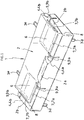
Fig. 1 is a conceptual perspective view showing an embodiment of a core material of a seat cushion for a vehicle according to the present invention. -
Fig. 2 is a conceptual plan view showing a state in which a frame member is buried in an expanded beads molded article of the core material of a seat cushion for a vehicle shown inFig. 1 . -
Fig. 3 is a sectional view taken along line X-X ofFig. 2 . -
Fig. 4 is a conceptual plan view showing a measurement position of warping of an example. -
Fig. 5 is a conceptual plan view showing another embodiment of a core material of a seat cushion for a vehicle. -
Fig. 6 is a sectional view taken along line Y-Y ofFig. 5 . - Hereinafter, a core material of a seat cushion for a vehicle of the present invention will be described in detail.
- The core material of a seat cushion for a vehicle according to the present invention which is a core material for a vehicle including: a thermoplastic resin expanded beads molded article having a substantially rectangular shape in a top view; and an annular frame member buried in the circumferential portion of the thermoplastic resin expanded beads molded article by insert molding. The expanded beads molded article includes: thick portions on a front side and on both sides of the expanded beads molded article; and an occupant seating portion on an upper surface in an inner region with respect to the circumferential portion. The frame member includes: a front frame portion; a rear frame portion; and two side frame portions connecting the front frame portion and the rear frame portion to each other. In the expanded beads molded article, first slits are formed, the first slits each having a slit piece along the front frame member at a position in front of the occupant seating portion and inside the front frame portion and another slit piece along the side frame portion at a position between outside of the occupant seating portion and inside of the side frame portion; and at least one second slit intersecting the frame member is formed at a position in the thick portions where the frame member is buried. Hereinafter, the "thermoplastic resin expanded beads molded article" is also simply referred to as an "expanded beads molded article".
- The thermoplastic resin constituting the expanded beads molded article can be appropriately selected. For example, the present invention can be suitably applied to the case where a polystyrene resin; a polyolefin resin such as polyethylene or polypropylene; a polyester resin such as polyethylene terephthalate or polylactic acid; or a composite resin of a polystyrene resin and a polyolefin resin may be used. Among them, since a resin containing a polyolefin resin which is a crystalline resin is easy to shrink, the effect of the present invention for preventing warping can be remarkably exhibited when the polyolefin resin is used. It is more preferable to use a polyethylene resin, a polypropylene resin, or a composite resin of a polystyrene resin and a polyolefin resin, and it is further more preferable to use a polypropylene resin.
- The thermoplastic resin expanded beads molded article in which the frame member is integrated by insert molding can be produced by a known method.
- For example, a dispersing medium (usually water) and optionally a surfactant is added to a pressurizable closed container such as an autoclave, and the above-described thermoplastic resin particles are dispersed therein, the foaming agent is injected, and the mixture is stirred under heating to impregnate the resin particles with the foaming agent. Then, the resin particles impregnated with the foaming agent are discharged from the inside of the container which is under high temperature and high pressure together with the dispersion medium to a low-pressure region (usually at atmospheric pressure) to manufacture expanded beads foamed at a predetermined magnification. Next, a mold in which the frame member is arranged in a predetermined position in advance is filled with the expanded beads, and in-mold molding is performed by introducing steam to fuse the expanded beads, the frame member and the expanded beads are integrated, thus the expanded beads molded article in which the frame member is buried can be manufactured as an integral molded article.
- The frame member used in the present invention is not particularly limited as long as the frame member is used as a frame member of the core material of a seat cushion for a vehicle. Examples thereof include: metal frame members made of iron, aluminum, copper, and the like; resin frame members made of an engineering plastic, a glass fiber reinforced resin, and the like, and these may be appropriately combined. The shape of the frame member is not particularly limited as long as the frame member functions as reinforcement during collision or attachment to the vehicle body, but is at least an annular shape that can be disposed at the circumferential portion of the thermoplastic resin expanded beads molded article. In a case of the annular frame member, one may have frame members having different rigidities connected to each other. For example, the front side where the highest strength is required may be formed of a frame member having a high rigidity, and both sides and the rear side may be formed of linear frame members thinner than the front side, or may be formed by interposing a different material in a part thereof. Further, when the frame member is an annular reinforcing member having a substantially quadrangular shape in top view, the shape of the front side half and the shape of the rear side half may be different. When the frame members whose material and shape are front-rear asymmetric are buried in the expanded beads molded article as described above, it is further difficult to predict the degree or direction of warping occurring in the core material.
- When normally used as a sheet for a vehicle, as shown in
Fig. 2 , it is preferable to use theannular frame member 3 formed in a substantially rectangular shape which suits for the outer peripheral shape of the expanded beads moldedarticle 2 so as to reinforce each side and four corners of thecore material 1 for a seat cushion for a vehicle when viewed from above. Further, the entire periphery of theannular frame member 3 is not necessarily buried in the expanded beads molded article, and for example, a part of theframe member 3 may be exposed from the expanded beads moldedarticle 2 in order to attach theframe member 3 to the vehicle body or to attach other members to the core material of a seat cushion for a vehicle. - In the illustrated embodiment, the
frame member 3 has a substantially quadrangular annular shape, and has a front-rear asymmetric shape having different shapes between the front side half and the rear side half. Theframe member 3 includes a linearfront frame portion 3a having a thickness of approximately 4.5 mm, aframe portion 3b having a C shape in a plan view and a thickness of approximately 4.5 mm, andplate portions 3c connecting thefront frame portion 3a and theframe portion 3b. Theframe portion 3b includes arear frame portion 3b-1 corresponding to a rear direction of the vehicle in a state in which the core material of a seat cushion for a vehicle is attached, and twoside frame portions 3b-2 that connect the front frame portion and the rear frame portion to each other. Ametal hook 3d for attaching to the vehicle is joined to each of theplate portions 3c, and twometal hooks 3e for connecting to the back sheet are joined to the C-shaped wire member 3b. The number of these hooks is not particularly limited. - The thermoplastic resin expanded beads molded
article 2 is formed in a generally rectangular shape in a top view. The thermoplastic resin expanded beads moldedarticle 2 includes thick portions 4a, 4b on a front side portion 2a and bothside portions 2b of the circumferential portion. The size of the thermoplastic resin expanded beads moldedarticle 2 is appropriately designed according to the vehicle to be mounted, but the length in the long side direction is generally about 1000 mm to 1400 mm, and the length in the short side direction is generally about 400 mm to 600 mm. In the illustrated embodiment, recessedportions portion 6 serving as the occupant seating portion is preferably 15 mm to 40 mm, and more preferably 20 mm to 35 mm. The difference between the thickness of the thermoplastic resin expanded beads molded article at the position of the recessedportion 6 serving as the occupant seating portion and the thickness of the thermoplastic resin expanded beads molded article in the thick portion 4a of the front side portion 2a is preferably 60 mm to 165 mm, and more preferably 85 mm to 140 mm for preventing the occupant slipping off. From the same viewpoint, the thickness of the thermoplastic resin expanded beads molded article in the thick portions 4a, 4b existing in the front side portion 2a and theside portions - First slits 7 (7a, 7b) are formed along the
frame member 3 at an inner side of theframe member 3 which is buried in front and outside of the recessedportions 6 serving as the occupant seating portions. In the present invention, by forming the first slits 7 (7a, 7b) along the frame member, it is possible to effectively prevent the warping due to the difference in the shrinkage amount between the expanded beads moldedarticle 2 and theframe member 3. It is considered that this is because the formed first slits 7 (7a, 7b) can separate the occupant seating portion and the thick portions in which the frame member at the periphery thereof is buried, and can relieve the tensile force caused by the difference in the shrinkage ratio of the respective portions. Furthermore, since theframe member 3 is not exposed by the first slits 7 (7a, 7b), the integrity of the expanded beads moldedarticle 2 and theframe member 3 is not impaired. From the viewpoint of causing such an effect, the first slits 7 (7a, 7b) are preferably formed at the inner position separated by 10 mm to 70 mm away from theframe member 3, and more preferably formed at the inner position separated by 30 mm to 50 mm. - The
first slits 7 include slit pieces 7a along the front frame member at a position in front of the occupant seating portion and inner side of the front frame member (hereafter, also referred to as "long side pieces") and slit pieces 7b along the side frame member at a position outside of the occupant seating portion and inner side of the side frame member (hereafter, also referred to as "short side pieces"), and are disposed such that the long side pieces 7a and the short side pieces 7b form an L-shape. Hereinafter, the long side pieces 7a and the short side pieces 7b are collectively referred to as "substantially L-shapedslits 7". When the length of the expanded beads moldedarticle 2 in the long side direction is 100%, the long side pieces 7a are preferably formed in a range of 20% to 40%, and more preferably in a range of 25% to 35%. When the length of the expanded beads moldedarticle 2 in the short side direction is 100%, the short side pieces 7b are preferably formed in a range of 30% to 60%, and more preferably in a range of 35% to 55%. The widths of the slits 7 (7a, 7b) are preferably 50 mm or less, and more preferably 20 mm or less, and further more preferably 15 mm or less. The lower limit is approximately 0.1 mm. When the first slits 7 (7a, 7b) are formed during in-mold molding, the widths of theslits 7 are preferably 5 mm or more, and more preferably 10 mm or more. - Further, the thermoplastic resin expanded beads molded
article 2 preferably includes connecting portions for connecting the portions of the expanded beads moldedarticle 2 closer to the recessedportions 6 than thefirst slits 7 and the portions thereof closer to theframe member 3 than thefirst slits 7 from a viewpoint of stabilizing a separation portion between the occupant seating portion and the thick portion of the circumferential thereof between the slit pieces 7a and the slit pieces 7b of thefirst slits 7 formed along the frame member. In the illustrated embodiment, connectingportions 8 that divide thefirst slits 7 into long side pieces 7a and short side pieces 7b are provided. When the connectingportions 8 are provided between the long side pieces 7a and the short side pieces 7b, a connecting portion having a length of 10 mm to 70 mm is preferably provided, and a connecting portion having a length of 20 mm to 40 mm is more preferably povided. The length of the connecting portion means a distance between adjacent ends of the pieces 7a, 7b of thefirst slits 7. Thefirst slits 7 are preferably slits passing through in the thickness direction of the expanded beads moldedarticle 2 from the viewpoint of the above-described separation effect. However, thefirst slits 7 may include a bottom portion on at least a part of the upper surface side or the lower surface side of the connectingportion 8, and may have a slit connecting the pieces 7a and 7b. A soft synthetic resin foam such as urethane foam is laminated on the upper surface and/or the side surface of the core material of a seat cushion for a vehicle. From the viewpoint of preventing the urethane foam and the like from entering the upper surface of the core material of a seat cushion for a vehicle, at least a part of thefirst slits 7 is preferably a slit having a bottom portion on the upper surface side, and as shown inFigs. 5 and6 , it is more preferable that the entirety of thefirst slits 7 is a slit that is recessed in the thickness direction from the lower surface of the expanded beads moldedarticle 2. When thefirst slits 7 include a slit having a bottom portion on at least a part of the upper surface side or the lower surface side of the connectingportion 8, or as shown inFigs. 5 and6 , when the entirety of thefirst slits 7 includes a bottom portion, the thickness of the expanded beads moldedarticle 2 at the bottom portion is preferably 25 mm or less, and more preferably 15 mm or less. When thefirst slits 7 having the bottom portion is formed during in-mold molding, the lower limit of the thickness of the expanded beads moldedarticle 2 at the bottom portion is preferably about 3 mm, and more preferably about 5 mm. - In the present invention, the term "front side" means the direction of the core material of a seat cushion for a vehicle that corresponds to the front direction of the vehicle in a state in which the core material of a seat cushion for a vehicle according to the present invention is attached to the vehicle, the term "side" means the direction of the core material of a seat cushion for a vehicle that is in the width direction of the vehicle, and the term "rear side" means the direction of the core material of a seat cushion for a vehicle that corresponds to the rear direction of the vehicle in a state in which the core material of a seat cushion for a vehicle according to the present invention is attached to the vehicle. The term "upper surface" means a surface on the seat surface side of the core material of a seat cushion for a vehicle, and the "lower surface" means a surface on the opposite side thereof.
- In the
core material 1 of a seat cushion for a vehicle according to the present invention, at least one slit 9 (second slit) intersecting the frame member is formed at a position which is in thethick portion 4 of the thermoplastic resin expanded beads moldedarticle 2 and at a position where theframe member 3 is buried. In the present invention, in order to reduce the variation in the shrinkage amount at a specific portion of the expanded beads moldedarticle 2 due to the fact that theframe member 3 is buried, theslit 9 is formed at a position of thethick portion 4 where theframe member 3 is buried, which is considered to have a large difference of the shrinkage, to relieve the deformation. - The
slit 9 may be formed so as to pass through the expanded beads moldedarticle 2 in the vertical direction. However, in order to suppress the occurrence of warping without impairing the integrity of the core material, it is preferable that at least one bottomedslit 9 recessed in the thickness direction is formed from at least one of the upper surface and the lower surface of the expanded beads moldedarticle 2 in thethick portion 4. The bottomed slit 9 is preferably formed so as to extend in a direction intersecting the length direction of theframe member 3 at a position corresponding to a portion where theframe member 3 is buried of at least one of the upper surface and the lower surface of the expanded beads moldedarticle 2. - In the
core material 1 of a seat cushion for a vehicle, as shown inFig. 3 , theframe member 3 is often positioned on the lower surface side in the thickness direction of the expanded beads moldedarticle 2. Therefore, it is preferable that theslit 9 is formed at least on the upper surface of the expanded beads moldedarticle 2 and on the upper surface side of theframe member 3. The depth of theslit 9 formed in the expanded beads moldedarticle 2 in the present invention is preferably such that the length (α) in the thickness direction from the bottom portion of theslit 9 formed on the upper surface of the expanded beads moldedarticle 2 to theframe member 3 is substantially equal to the length (β) in the thickness direction from the lower surface to theframe member 3. It is preferable that a slit has a depth such that the difference between the lengths of the (α) and (β) is within ± 60 mm, and it is more preferable that a slit has a depth such that the difference is within ± 40 mm. Further, theslits 9 may be respectively formed from the upper surface and the lower surface of the expanded beads moldedarticle 2 toward theframe member 3. When theslits 9 are respectively formed toward theframe member 3 from the upper surface and the lower surface of the expanded beads moldedarticle 2, it is preferably such that the length in the thickness direction from the bottom portion of the slit formed on the upper surface of the expanded beads moldedarticle 2 to theframe member 3 is substantially equal to the length in the thickness direction from the bottom portion formed on the lower surface to theframe member 3. In the case where each of theslits 9 is formed from the upper surface and the lower surface of the expanded beads moldedarticle 2 toward theframe member 3, it is preferable that a slit having a depth such that the difference is within ± 60 mm is formed, and a slit having a depth such that the difference is within ± 40 mm is more preferably formed. - In the case where the
slits 9 are formed from the upper surface and the lower surface of the expanded beads moldedarticle 2 toward theframe member 3, the slits on the upper surface and the lower surface may be formed at a pair of opposed positions, but slits on the lower surface may be formed in the middle of the twoslits 9 formed on the upper surface, for example. - The direction in which the
slit 9 is formed is appropriately set according to the shape and size of thecore material 1 of a seat cushion for a vehicle to be manufactured so as to intersect theframe member 3. Here, the intersection means a state in which theframe member 3 intersects theslit 9 in a two-dimensional plane in which thecore material 1 of a seat cushion for a vehicle is observed from the upper surface. However, the intersecting angle between theframe member 3 and theslit 9 is not particularly limited, but preferably, theslit 9 is formed to intersect theframe member 3 in a substantially perpendicular direction. Preferably, theslits 9 are formed at positions equally dividing the length in the long side direction or the length in the short side direction of thecore material 1 of a seat cushion for a vehicle. In the illustrated embodiment, the slits 9a, 9b are formed at two positions that divide thecore material 1 in the long side direction into three substantially equal parts and at one position that divides the core material into two substantially equal parts in the short direction. - The length of the
slit 9 to be formed is preferably 50 mm or more, more preferably 100 mm or more, including an intersection portion with theframe member 3. Similar to theslit 7, the width of theslit 9 to be formed is preferably 50 mm or less, more preferably 20 mm or less, and even more preferably 15 mm or less. The lower limit is approximately 0.1 mm. When the substantially slits 9 are formed by molding in-mold molding, the widths of theslits 9 are preferably 5 mm or more, and more preferably 10 mm or more. - It is preferable that the
slit 9 formed to intersect theframe member 3 is formed so as to intersect theslit 7 formed along theframe member 3. As a result, the warping of the core material can be further suppressed. Similar to the above, the intersection means a state in which theslit 9 intersects theslit 7 in a two-dimensional plane in which thecore material 1 of a seat cushion for a vehicle is observed from the upper surface. In the illustrated embodiment, the slits 9a formed at two positions that substantially equally divide thecore material 1 into three equal parts in the long side direction are formed to intersect the pieces 7a in the long side direction of the substantially L-shapedslit 7 formed along the frame member respectively in a cross shape. Further, the slit 9b formed at one position at which thecore material 1 is divided into two substantially equal parts in the short side direction is formed to communicate with the short side piece 7b of theslit 7 formed along the frame member in a T-shape. - In view of productivity, it is preferable that the
slit 7 formed along theframe member 3 of thecore material 1 of a seat cushion for a vehicle of the present invention and theslit 9 formed to intersect theframe member 3 in thethick portion 4 are formed at the same time as the molding of the expanded beads moldedarticle 2 by providing protrusions for forming theslits slits core material 1 of a seat cushion for a vehicle molded by the molding device by using a cutter, a heat ray, and the like. In the case where theslits - The core material of a seat cushion for a vehicle of the present invention described above is attached to the vehicle body, a soft synthetic resin foam such as urethane foam is laminated on the upper surface and/or the side surface of the core material of a seat cushion for a vehicle. Further, the vehicular seat is formed by covering the outer peripheral surfaces of the front surface, the side surface, and the upper portion of the laminate with a skin material such as woven or knitted fabric, vinyl leather, or leather.
- Note that the soft synthetic resin foam refers to a soft foamed urethane which is mainly used as the material of the seat cushion or a resin foam which is softened by increasing the foaming ratio with a resin material different from soft foamed urethane. By using the core material of a seat cushion for a vehicle of the present invention, the use amount of the soft synthetic resin foam can be reduced and a vehicle seat having excellent light weight can be formed.
- Hereinafter, the core material of a seat cushion for a vehicle of the present invention will be described in more detail with reference to Examples, but the present invention is not limited to the Examples.
- Six core materials of a seat cushion for a vehicle of a vehicle rear seat in which the expanded beads molded article and the frame member are integrated by using a molding device were manufactured.
- As the expanded beads, polypropylene resin expanded beads (expansion ratio: 30 times, expanded beads diameter: approximately 3.5 mm) were used.
- As the frame member, an annular frame member shown in
Figs. 2 and3 was used. A metal substantially linear wire member having a thickness of 4.5 mm and a metal wire member with a thickness of 4.5 mm and a C-shape in top view and one bent portion in a side view and having a step of 30 mm in the vertical direction are connected to each other by a plate portion, a frame member was formed in a substantially quadrangular shape in top view and having a front-rear asymmetrical shape with a length of 1040 mm in the long side direction (width direction), a length of 400 mm in the short side direction (front-rear direction) and a step of 30 mm in the vertical direction. - The molding mold in which the frame member was disposed in advance was filled with the expanded beads, and in-mold molding was performed by steam heating. In the heating method, the steam of 0.30 MPa (G) was supplied from both molds for 8 seconds to perform preheating in a state in which drain valves of the both molds were opened (an exhaust process), and the steam of 0.22 MPa (G) was supplied from the mold for 15 seconds to perform heating from one mold, and the steam of 0.26 MPa (G) was supplied from the other mold for 20 seconds to perform heating from the other mold, and then the steam of 0.30 MPa (G) was supplied from both molds for 4 seconds to perform the main heating. After the completion of heating, the pressure was relieved, the molds were air-cooled down for 10 seconds, and were water-cooled for 110 seconds, so that a core material of a seat cushion for a vehicle was obtained by integrating the expanded beads molded article and the frame member.
- The obtained core material of a seat cushion for a vehicle has a substantially rectangular shape in top view including thick portions on the front side and both sides of the expanded beads molded article, and so that two recessed portions serving as two occupant seating portions are formed side by side in the long side direction on the upper surface inside the circumferential portion of the expanded beads molded article.
- Next, for three core materials of a seat cushion for a vehicle, by using a cutter knife, as shown in
Figs. 1 to 3 , immediately after the core material was removed from the mold (within 180 seconds), substantially L-shaped slits 7 (long side pieces 7a and short side pieces 7b) along the frame member are formed at the inner position (between the frame member and the occupant seat) with respect to the frame member buried in the front and both sides of the occupant seating portion, theslits 9 intersecting the frame member are formed on a position which is in the thick portion and at a position where the frame member is buried. The substantially L-shapedslits 7 were formed to pass through the expanded beads molded article in the thickness direction at the inner position 40 mm away from the frame member. The lengths of the long side pieces 7a of the substantially L-shaped slits was formed in a range of over 29% when the length of the expanded beads molded article in the long side direction was 100%. The lengths of the short side pieces 7b of the substantially L-shaped slits was formed in a range of over 44% when the length of the expanded beads molded article in the short side direction was 100%. The widths of the substantially L-shapedslits 7 were 12 mm. Connecting portions were left between the long side pieces 7a and the short side pieces 7b of the substantially L-shapedslits 7, and the lengths of the connecting portion were 30 mm. As theslits 9 intersecting with the frame member, slits recessed in the thickness direction from the upper surface of the expanded beads molded article were formed respectively at two positions that divide the expanded beads molded article into substantially three equal parts in the long side direction, and at one position that divides the expanded beads molded article into substantially two equal parts in the short side direction. The depths of theslits 9 were formed such that the difference (α-β) between the length (α) in the thickness direction from the bottom portion of the slits to the frame member and the length (β) in the thickness direction from the lower surface of the expanded beads molded article to the frame member is -60 mm, the lengths of theslits 9 were formed by a length of 200 mm including an intersection portion with the frame member, the widths of theslits 9 were 12 mm. - Each of the three core materials of a seat cushion for a vehicle (Examples) having the slits and the remaining three core materials of a seat cushion for a vehicle (Comparative Examples) not having the slits were subjected to stand in an atmosphere of 60°C for 12 hours for curing, and then the warping of the core materials for vehicular seat cushions in Examples and Comparative Examples were measured by the following method, and the evaluation was performed.
- The core materials in Examples and Comparative Examples had a length of 1210 mm in the long side direction and a length of 500 mm in the short side direction, the thickness of the recessed portion serving as the occupant seating portion was 20 mm to 25 mm, and the thickness of the thick portion existing in front side and both sides was 130 mm to 140 mm.
- The amount of displacement (mm) from the reference position was measured at the positions of A to F shown in
Fig. 4 by placing the seat surface side of the core material of a seat cushion for a vehicle on an inspection jig. - It should be noted that the case where the position is higher than the reference position is denoted by "+" and the case where the position is lower than the reference position is denoted by "-".
- The arithmetic mean values of the respective measurement results in three Examples and three Comparative Examples are shown in Table 1.
[Table 1] Point A Point B Point C Point D Point E Point F Examples (with slit) -1.0 -2.0 ±0 -1.0 +1.0 +3.0 Comparative Examples (without slit) -6.0 -5.0 -6.0 -5.0 +5.0 +6.0 Unit: mm - It can be seen from Table 1 that in Examples in which the slits are formed, the deformation amount of the product is smaller than the product of the Comparative Examples in which no slit exists, the warping of the expanded beads molded article is reduced, and the product value is excellent.
- From the above results, it was confirmed that the core material of a seat cushion for a vehicle having a light weight, less warping, and extremely excellent commodity value can be provided by forming slits under specific conditions in the present invention.
- The present application is based on Japanese Patent Application No.
2017-035718 filed on Feb 28, 2017 - According to the present invention, since a core material of a seat cushion for a vehicle can be provided, which is made of a thermoplastic resin expanded beads molded article in which a frame member is integrated, has less warping and excellent dimensional precision, a soft synthetic resin foam such as urethane foam is laminated on the core material of a seat cushion for a vehicle, and the outer peripheral surface of the laminate can be widely used as a vehicle seat by further covering the outer peripheral surface with a skin material such as woven or knitted fabric, vinyl leather, or leather.
Claims (4)
- A core material of a seat cushion for a vehicle comprising:a thermoplastic resin expanded beads molded article having a substantially rectangular shape in a top view; andan annular frame member buried in the circumferential portion of the thermoplastic resin expanded beads molded article by insert molding,the expanded beads molded article comprising:thick portions on a front side and on both sides of the expanded beads molded article; andan occupant seating portion on an upper surface in an inner region with respect to the circumferential portion;the frame member comprising:a front frame portion;a rear frame portion; andtwo side frame portions connecting the front frame portion and the rear frame portion to each other;wherein, in the expanded beads molded article,first slits are formed, the first slits each having a slit piece along the front frame member at a position in front of the occupant seating portion and inner side of the front frame portion and another slit piece along the side frame portion at a position between outside of the occupant seating portion and inside of the side frame portion; andat least one second slit intersecting the frame member is formed at a position in the thick portions where the frame member is buried.
- The core material of a seat cushion for a vehicle according to claim 1,
wherein the first slit is recessed in the thickness direction from a lower surface of the expanded beads molded article. - The core material of a seat cushion for a vehicle according to claim 1 or 2,
wherein the second slit is recessed in the thickness direction from at least one of an upper surface and a lower surface of the expanded beads molded article. - The core material of a seat cushion for a vehicle according to any one of claims 1 to 3,
wherein the second slit intersects the first slit.
Applications Claiming Priority (2)
| Application Number | Priority Date | Filing Date | Title |
|---|---|---|---|
| JP2017035718A JP6761768B2 (en) | 2017-02-28 | 2017-02-28 | Vehicle seat cushion core material |
| PCT/JP2018/006960 WO2018159529A1 (en) | 2017-02-28 | 2018-02-26 | Vehicle seat cushion core |
Publications (3)
| Publication Number | Publication Date |
|---|---|
| EP3590391A1 true EP3590391A1 (en) | 2020-01-08 |
| EP3590391A4 EP3590391A4 (en) | 2020-10-14 |
| EP3590391B1 EP3590391B1 (en) | 2022-03-30 |
Family
ID=63370002
Family Applications (1)
| Application Number | Title | Priority Date | Filing Date |
|---|---|---|---|
| EP18761896.2A Active EP3590391B1 (en) | 2017-02-28 | 2018-02-26 | Vehicle seat cushion core |
Country Status (6)
| Country | Link |
|---|---|
| US (1) | US10875436B2 (en) |
| EP (1) | EP3590391B1 (en) |
| JP (1) | JP6761768B2 (en) |
| KR (1) | KR102315135B1 (en) |
| CN (1) | CN110352024B (en) |
| WO (1) | WO2018159529A1 (en) |
Families Citing this family (5)
| Publication number | Priority date | Publication date | Assignee | Title |
|---|---|---|---|---|
| JP6745211B2 (en) * | 2016-12-28 | 2020-08-26 | 株式会社ジェイエスピー | Sheet core material |
| DE102017113098A1 (en) * | 2017-06-14 | 2018-12-20 | Proseat Gmbh & Co. Kg | Upholstered part of a vehicle seat with a foamed 3D molded fabric for stiffening a side wall |
| JP6606533B2 (en) * | 2017-08-21 | 2019-11-13 | 積水化成品工業株式会社 | Vehicle seat core and seat pad |
| JP7153059B2 (en) * | 2018-03-01 | 2022-10-13 | 株式会社カネカ | seat core material |
| JPWO2024232084A1 (en) * | 2023-05-11 | 2024-11-14 |
Family Cites Families (58)
| Publication number | Priority date | Publication date | Assignee | Title |
|---|---|---|---|---|
| US3630572A (en) * | 1969-09-23 | 1971-12-28 | Lear Siegler Inc | Seat assembly |
| US3649974A (en) * | 1969-12-15 | 1972-03-21 | Universal Oil Prod Co | Vehicle seat |
| US4609226A (en) * | 1984-08-14 | 1986-09-02 | Tachikawa Spring Co., Ltd. | Vehicle seat |
| IT210581Z2 (en) * | 1987-02-20 | 1988-12-30 | Fiat Auto Spa | COMPLEX FOR ANCHORING A COVERING TO A PADDING OF A VEHICLE SEAT |
| JPH05154929A (en) | 1991-12-09 | 1993-06-22 | Kanegafuchi Chem Ind Co Ltd | Composite foam molded article and method for producing the same |
| JPH0662901A (en) * | 1992-08-14 | 1994-03-08 | Masanari Kuroda | Overshoe |
| FR2790429B1 (en) * | 1999-03-03 | 2001-05-04 | Faure Bertrand Equipements Sa | SEAT FOR A MOTOR VEHICLE COATED WITH A REMINDER CAP |
| JP4461532B2 (en) * | 1999-12-08 | 2010-05-12 | 株式会社ブリヂストン | Vehicle seat and manufacturing method thereof |
| DE10131718C1 (en) * | 2001-06-29 | 2003-01-02 | Faurecia Autositze Gmbh & Co | Seat, in particular motor vehicle seat |
| US6592181B2 (en) * | 2001-08-31 | 2003-07-15 | Intier Automotive Inc. | Tunnel cord trim retainer |
| CN100398037C (en) * | 2001-11-26 | 2008-07-02 | 株式会社普利司通 | Seat cushion for vehicle |
| JP3735681B2 (en) * | 2002-07-08 | 2006-01-18 | 日本発条株式会社 | Automotive seat |
| US7296852B2 (en) * | 2004-05-11 | 2007-11-20 | Moeller Marine Products | Upholstered seat |
| US6964453B1 (en) * | 2004-06-02 | 2005-11-15 | Irvin Automotive Products, Inc. | Seat trim cover assembly aid |
| DE102005012320A1 (en) * | 2005-03-17 | 2006-09-21 | Faurecia Autositze Gmbh & Co. Kg | Motor vehicle seat, has attachment units fastened to base of groove and rested on other attachment units that are fastened to cover, where units are halves of sliding gate or slide fastener with slider that is accommodated in groove |
| WO2006102751A1 (en) * | 2005-03-30 | 2006-10-05 | Woodbridge Foam Corporation | Foam seat element, mold for the production thereof and method to manufacture the mold |
| US8091184B2 (en) * | 2007-04-19 | 2012-01-10 | Hope Global, Division Of Nfa Corp. | Festooned trim clip system and method for attaching festooned clips to a substrate |
| US20090033131A1 (en) * | 2007-08-01 | 2009-02-05 | Lear Corporation | Vehicle seat trim attachment |
| US7946649B2 (en) * | 2007-10-01 | 2011-05-24 | Lear Corporation | Vehicle seat assembly having layered seating system with attachment member |
| US9061610B2 (en) * | 2007-12-06 | 2015-06-23 | Lear Corporation | Layered seating with directed deflection for child seat and occupant safety |
| US8919887B2 (en) * | 2008-05-22 | 2014-12-30 | Delta Tooling Co., Ltd. | Elastic member made of expanded resin beads, laminated elastic structural body, and seat structure |
| US9555728B2 (en) * | 2008-06-03 | 2017-01-31 | Lear Corporation | Layered seating system with attachments |
| JP5277912B2 (en) * | 2008-11-28 | 2013-08-28 | トヨタ紡織株式会社 | Vehicle seat |
| JP5356157B2 (en) | 2009-08-28 | 2013-12-04 | 積水化成品工業株式会社 | Vehicle seat core |
| US8398166B2 (en) * | 2010-03-11 | 2013-03-19 | Honda Motor Co., Ltd. | Vehicle seat assembly |
| US8308235B2 (en) * | 2010-03-11 | 2012-11-13 | Honda Motor Co. | Vehicle seat assembly |
| US8408655B2 (en) * | 2010-08-27 | 2013-04-02 | Honda Motor Co., Ltd. | Vehicle seat assembly |
| US8191971B2 (en) * | 2010-03-17 | 2012-06-05 | Lear Corporation | Seat trim assembly |
| US8590978B2 (en) * | 2010-09-15 | 2013-11-26 | Ford Global Technologies, Llc | Ultra-thin seat carrier |
| US8540318B2 (en) * | 2011-01-20 | 2013-09-24 | Lear Corporation | Vehicle seating frame attachment assembly, and method of making the same |
| US8662583B2 (en) * | 2011-01-24 | 2014-03-04 | Lear Corporation | Vehicle seat trim attachment |
| JP5782906B2 (en) * | 2011-08-04 | 2015-09-24 | トヨタ紡織株式会社 | Vehicle seat |
| US10160357B2 (en) * | 2012-05-07 | 2018-12-25 | Lear Corporation | Seat assembly having improved trim appearance and method and tool for making the same |
| JP6003724B2 (en) * | 2013-03-06 | 2016-10-05 | トヨタ紡織株式会社 | Emergency hanging structure |
| JP6107460B2 (en) * | 2013-06-19 | 2017-04-05 | トヨタ紡織株式会社 | Vehicle seat and manufacturing method thereof |
| CN104340099B (en) * | 2013-07-31 | 2017-06-06 | 东洋橡胶工业株式会社 | Seat cushion |
| JP6377909B2 (en) * | 2014-01-22 | 2018-08-22 | 株式会社カネカ | Mold for foam molding in olefin resin mold |
| JP6154345B2 (en) * | 2014-03-14 | 2017-06-28 | 株式会社ジェイエスピー | Automotive seat components |
| JP6471748B2 (en) * | 2014-04-15 | 2019-02-20 | 株式会社カネカ | Polyolefin resin mold for in-mold foam molding, method for producing in-mold foam molded article, and in-mold foam molded article |
| JP6179458B2 (en) * | 2014-05-20 | 2017-08-16 | トヨタ紡織株式会社 | Vehicle seat |
| JP6013530B2 (en) * | 2014-08-28 | 2016-10-25 | トヨタ紡織株式会社 | Vehicle seat |
| JP6062901B2 (en) * | 2014-09-16 | 2017-01-18 | 株式会社ジェイエスピー | Manufacturing method of seat core material for vehicle and seat seat core material for vehicle |
| JP6307402B2 (en) * | 2014-09-25 | 2018-04-04 | 株式会社タチエス | Skin hanging structure |
| JP2016097948A (en) * | 2014-11-26 | 2016-05-30 | 株式会社タチエス | Sheet |
| JP6307419B2 (en) * | 2014-11-26 | 2018-04-04 | 株式会社タチエス | Sheet |
| JP6636263B2 (en) * | 2015-04-23 | 2020-01-29 | 株式会社タチエス | Sheet |
| JP6512944B2 (en) * | 2015-05-28 | 2019-05-15 | 株式会社ブリヂストン | Sheet pad and sheet pad manufacturing apparatus |
| JP6639145B2 (en) | 2015-08-11 | 2020-02-05 | 三機工業株式会社 | Pipe escape prevention structure for jig for caulking joint |
| WO2017094659A1 (en) * | 2015-12-02 | 2017-06-08 | 積水化成品工業株式会社 | Vehicular seat member and vehicular seat |
| JP6687382B2 (en) * | 2015-12-21 | 2020-04-22 | 株式会社ジェイエスピー | Vehicle seat core material manufacturing method and vehicle seat core material |
| JP6835749B2 (en) * | 2016-02-04 | 2021-02-24 | 株式会社ジェイエスピー | Vehicle seat seat core material |
| WO2018030484A1 (en) * | 2016-08-10 | 2018-02-15 | 積水化成品工業株式会社 | Vehicle seat member and method of manufacturing same |
| EP3501890B1 (en) * | 2016-08-17 | 2022-04-13 | Sekisui Plastics Co., Ltd. | Vehicular seat member and method for manufacturing same |
| US10807507B2 (en) * | 2017-02-08 | 2020-10-20 | Jsp Corporation | Seat core material |
| JP7041082B2 (en) * | 2017-02-17 | 2022-03-23 | 株式会社ジェイエスピー | Sheet core material |
| JP6788523B2 (en) * | 2017-02-28 | 2020-11-25 | 株式会社ジェイエスピー | Vehicle seat cushion core material |
| JP6991822B2 (en) * | 2017-10-10 | 2022-02-03 | トヨタ紡織株式会社 | Vehicle seat |
| JP7124304B2 (en) * | 2017-12-08 | 2022-08-24 | トヨタ紡織株式会社 | vehicle seat |
-
2017
- 2017-02-28 JP JP2017035718A patent/JP6761768B2/en active Active
-
2018
- 2018-02-26 KR KR1020197024923A patent/KR102315135B1/en active Active
- 2018-02-26 CN CN201880014218.9A patent/CN110352024B/en active Active
- 2018-02-26 EP EP18761896.2A patent/EP3590391B1/en active Active
- 2018-02-26 US US16/489,039 patent/US10875436B2/en active Active
- 2018-02-26 WO PCT/JP2018/006960 patent/WO2018159529A1/en not_active Ceased
Also Published As
| Publication number | Publication date |
|---|---|
| US20200062157A1 (en) | 2020-02-27 |
| CN110352024B (en) | 2021-06-08 |
| EP3590391B1 (en) | 2022-03-30 |
| EP3590391A4 (en) | 2020-10-14 |
| US10875436B2 (en) | 2020-12-29 |
| CN110352024A (en) | 2019-10-18 |
| JP2018140701A (en) | 2018-09-13 |
| JP6761768B2 (en) | 2020-09-30 |
| WO2018159529A1 (en) | 2018-09-07 |
| KR20190124222A (en) | 2019-11-04 |
| KR102315135B1 (en) | 2021-10-20 |
Similar Documents
| Publication | Publication Date | Title |
|---|---|---|
| EP3590391B1 (en) | Vehicle seat cushion core | |
| JP6154345B2 (en) | Automotive seat components | |
| EP3196069B1 (en) | Method for manufacturing vehicle seat core member and vehicle seat core member | |
| US10631650B2 (en) | Core material of vehicular seat cushion | |
| EP3583869B1 (en) | Seat core material | |
| CN110121281B (en) | Chip material | |
| EP3581067B1 (en) | Seat core material | |
| JP6745677B2 (en) | Vehicle seat member and manufacturing method thereof | |
| JP6242472B2 (en) | Manufacturing method of seat core material for vehicle and seat seat core material for vehicle | |
| US11571843B2 (en) | Foam molding mold and method for manufacturing foam molding body |
Legal Events
| Date | Code | Title | Description |
|---|---|---|---|
| STAA | Information on the status of an ep patent application or granted ep patent |
Free format text: STATUS: THE INTERNATIONAL PUBLICATION HAS BEEN MADE |
|
| PUAI | Public reference made under article 153(3) epc to a published international application that has entered the european phase |
Free format text: ORIGINAL CODE: 0009012 |
|
| STAA | Information on the status of an ep patent application or granted ep patent |
Free format text: STATUS: REQUEST FOR EXAMINATION WAS MADE |
|
| 17P | Request for examination filed |
Effective date: 20190827 |
|
| AK | Designated contracting states |
Kind code of ref document: A1 Designated state(s): AL AT BE BG CH CY CZ DE DK EE ES FI FR GB GR HR HU IE IS IT LI LT LU LV MC MK MT NL NO PL PT RO RS SE SI SK SM TR |
|
| AX | Request for extension of the european patent |
Extension state: BA ME |
|
| DAV | Request for validation of the european patent (deleted) | ||
| DAX | Request for extension of the european patent (deleted) | ||
| A4 | Supplementary search report drawn up and despatched |
Effective date: 20200910 |
|
| RIC1 | Information provided on ipc code assigned before grant |
Ipc: A47C 27/14 20060101AFI20200904BHEP Ipc: B60N 2/90 20180101ALI20200904BHEP Ipc: A47C 7/20 20060101ALI20200904BHEP Ipc: B60N 2/70 20060101ALI20200904BHEP |
|
| RIC1 | Information provided on ipc code assigned before grant |
Ipc: A47C 27/14 20060101AFI20210512BHEP Ipc: A47C 7/20 20060101ALI20210512BHEP Ipc: B60N 2/90 20180101ALI20210512BHEP Ipc: B60N 2/70 20060101ALI20210512BHEP |
|
| GRAP | Despatch of communication of intention to grant a patent |
Free format text: ORIGINAL CODE: EPIDOSNIGR1 |
|
| STAA | Information on the status of an ep patent application or granted ep patent |
Free format text: STATUS: GRANT OF PATENT IS INTENDED |
|
| INTG | Intention to grant announced |
Effective date: 20210621 |
|
| GRAS | Grant fee paid |
Free format text: ORIGINAL CODE: EPIDOSNIGR3 |
|
| GRAJ | Information related to disapproval of communication of intention to grant by the applicant or resumption of examination proceedings by the epo deleted |
Free format text: ORIGINAL CODE: EPIDOSDIGR1 |
|
| GRAL | Information related to payment of fee for publishing/printing deleted |
Free format text: ORIGINAL CODE: EPIDOSDIGR3 |
|
| STAA | Information on the status of an ep patent application or granted ep patent |
Free format text: STATUS: REQUEST FOR EXAMINATION WAS MADE |
|
| GRAP | Despatch of communication of intention to grant a patent |
Free format text: ORIGINAL CODE: EPIDOSNIGR1 |
|
| STAA | Information on the status of an ep patent application or granted ep patent |
Free format text: STATUS: GRANT OF PATENT IS INTENDED |
|
| INTC | Intention to grant announced (deleted) | ||
| INTG | Intention to grant announced |
Effective date: 20211124 |
|
| GRAA | (expected) grant |
Free format text: ORIGINAL CODE: 0009210 |
|
| STAA | Information on the status of an ep patent application or granted ep patent |
Free format text: STATUS: THE PATENT HAS BEEN GRANTED |
|
| AK | Designated contracting states |
Kind code of ref document: B1 Designated state(s): AL AT BE BG CH CY CZ DE DK EE ES FI FR GB GR HR HU IE IS IT LI LT LU LV MC MK MT NL NO PL PT RO RS SE SI SK SM TR |
|
| REG | Reference to a national code |
Ref country code: GB Ref legal event code: FG4D |
|
| REG | Reference to a national code |
Ref country code: CH Ref legal event code: EP |
|
| REG | Reference to a national code |
Ref country code: AT Ref legal event code: REF Ref document number: 1478413 Country of ref document: AT Kind code of ref document: T Effective date: 20220415 |
|
| REG | Reference to a national code |
Ref country code: DE Ref legal event code: R096 Ref document number: 602018033035 Country of ref document: DE |
|
| REG | Reference to a national code |
Ref country code: IE Ref legal event code: FG4D |
|
| REG | Reference to a national code |
Ref country code: LT Ref legal event code: MG9D |
|
| PG25 | Lapsed in a contracting state [announced via postgrant information from national office to epo] |
Ref country code: SE Free format text: LAPSE BECAUSE OF FAILURE TO SUBMIT A TRANSLATION OF THE DESCRIPTION OR TO PAY THE FEE WITHIN THE PRESCRIBED TIME-LIMIT Effective date: 20220330 Ref country code: RS Free format text: LAPSE BECAUSE OF FAILURE TO SUBMIT A TRANSLATION OF THE DESCRIPTION OR TO PAY THE FEE WITHIN THE PRESCRIBED TIME-LIMIT Effective date: 20220330 Ref country code: NO Free format text: LAPSE BECAUSE OF FAILURE TO SUBMIT A TRANSLATION OF THE DESCRIPTION OR TO PAY THE FEE WITHIN THE PRESCRIBED TIME-LIMIT Effective date: 20220630 Ref country code: LT Free format text: LAPSE BECAUSE OF FAILURE TO SUBMIT A TRANSLATION OF THE DESCRIPTION OR TO PAY THE FEE WITHIN THE PRESCRIBED TIME-LIMIT Effective date: 20220330 Ref country code: HR Free format text: LAPSE BECAUSE OF FAILURE TO SUBMIT A TRANSLATION OF THE DESCRIPTION OR TO PAY THE FEE WITHIN THE PRESCRIBED TIME-LIMIT Effective date: 20220330 Ref country code: BG Free format text: LAPSE BECAUSE OF FAILURE TO SUBMIT A TRANSLATION OF THE DESCRIPTION OR TO PAY THE FEE WITHIN THE PRESCRIBED TIME-LIMIT Effective date: 20220630 |
|
| REG | Reference to a national code |
Ref country code: NL Ref legal event code: MP Effective date: 20220330 |
|
| REG | Reference to a national code |
Ref country code: AT Ref legal event code: MK05 Ref document number: 1478413 Country of ref document: AT Kind code of ref document: T Effective date: 20220330 |
|
| PG25 | Lapsed in a contracting state [announced via postgrant information from national office to epo] |
Ref country code: LV Free format text: LAPSE BECAUSE OF FAILURE TO SUBMIT A TRANSLATION OF THE DESCRIPTION OR TO PAY THE FEE WITHIN THE PRESCRIBED TIME-LIMIT Effective date: 20220330 Ref country code: GR Free format text: LAPSE BECAUSE OF FAILURE TO SUBMIT A TRANSLATION OF THE DESCRIPTION OR TO PAY THE FEE WITHIN THE PRESCRIBED TIME-LIMIT Effective date: 20220701 Ref country code: FI Free format text: LAPSE BECAUSE OF FAILURE TO SUBMIT A TRANSLATION OF THE DESCRIPTION OR TO PAY THE FEE WITHIN THE PRESCRIBED TIME-LIMIT Effective date: 20220330 |
|
| PG25 | Lapsed in a contracting state [announced via postgrant information from national office to epo] |
Ref country code: NL Free format text: LAPSE BECAUSE OF FAILURE TO SUBMIT A TRANSLATION OF THE DESCRIPTION OR TO PAY THE FEE WITHIN THE PRESCRIBED TIME-LIMIT Effective date: 20220330 |
|
| PG25 | Lapsed in a contracting state [announced via postgrant information from national office to epo] |
Ref country code: SM Free format text: LAPSE BECAUSE OF FAILURE TO SUBMIT A TRANSLATION OF THE DESCRIPTION OR TO PAY THE FEE WITHIN THE PRESCRIBED TIME-LIMIT Effective date: 20220330 Ref country code: SK Free format text: LAPSE BECAUSE OF FAILURE TO SUBMIT A TRANSLATION OF THE DESCRIPTION OR TO PAY THE FEE WITHIN THE PRESCRIBED TIME-LIMIT Effective date: 20220330 Ref country code: RO Free format text: LAPSE BECAUSE OF FAILURE TO SUBMIT A TRANSLATION OF THE DESCRIPTION OR TO PAY THE FEE WITHIN THE PRESCRIBED TIME-LIMIT Effective date: 20220330 Ref country code: PT Free format text: LAPSE BECAUSE OF FAILURE TO SUBMIT A TRANSLATION OF THE DESCRIPTION OR TO PAY THE FEE WITHIN THE PRESCRIBED TIME-LIMIT Effective date: 20220801 Ref country code: ES Free format text: LAPSE BECAUSE OF FAILURE TO SUBMIT A TRANSLATION OF THE DESCRIPTION OR TO PAY THE FEE WITHIN THE PRESCRIBED TIME-LIMIT Effective date: 20220330 Ref country code: EE Free format text: LAPSE BECAUSE OF FAILURE TO SUBMIT A TRANSLATION OF THE DESCRIPTION OR TO PAY THE FEE WITHIN THE PRESCRIBED TIME-LIMIT Effective date: 20220330 Ref country code: CZ Free format text: LAPSE BECAUSE OF FAILURE TO SUBMIT A TRANSLATION OF THE DESCRIPTION OR TO PAY THE FEE WITHIN THE PRESCRIBED TIME-LIMIT Effective date: 20220330 Ref country code: AT Free format text: LAPSE BECAUSE OF FAILURE TO SUBMIT A TRANSLATION OF THE DESCRIPTION OR TO PAY THE FEE WITHIN THE PRESCRIBED TIME-LIMIT Effective date: 20220330 |
|
| PG25 | Lapsed in a contracting state [announced via postgrant information from national office to epo] |
Ref country code: PL Free format text: LAPSE BECAUSE OF FAILURE TO SUBMIT A TRANSLATION OF THE DESCRIPTION OR TO PAY THE FEE WITHIN THE PRESCRIBED TIME-LIMIT Effective date: 20220330 Ref country code: IS Free format text: LAPSE BECAUSE OF FAILURE TO SUBMIT A TRANSLATION OF THE DESCRIPTION OR TO PAY THE FEE WITHIN THE PRESCRIBED TIME-LIMIT Effective date: 20220730 Ref country code: AL Free format text: LAPSE BECAUSE OF FAILURE TO SUBMIT A TRANSLATION OF THE DESCRIPTION OR TO PAY THE FEE WITHIN THE PRESCRIBED TIME-LIMIT Effective date: 20220330 |
|
| REG | Reference to a national code |
Ref country code: DE Ref legal event code: R097 Ref document number: 602018033035 Country of ref document: DE |
|
| PG25 | Lapsed in a contracting state [announced via postgrant information from national office to epo] |
Ref country code: DK Free format text: LAPSE BECAUSE OF FAILURE TO SUBMIT A TRANSLATION OF THE DESCRIPTION OR TO PAY THE FEE WITHIN THE PRESCRIBED TIME-LIMIT Effective date: 20220330 |
|
| PLBE | No opposition filed within time limit |
Free format text: ORIGINAL CODE: 0009261 |
|
| STAA | Information on the status of an ep patent application or granted ep patent |
Free format text: STATUS: NO OPPOSITION FILED WITHIN TIME LIMIT |
|
| 26N | No opposition filed |
Effective date: 20230103 |
|
| PG25 | Lapsed in a contracting state [announced via postgrant information from national office to epo] |
Ref country code: SI Free format text: LAPSE BECAUSE OF FAILURE TO SUBMIT A TRANSLATION OF THE DESCRIPTION OR TO PAY THE FEE WITHIN THE PRESCRIBED TIME-LIMIT Effective date: 20220330 |
|
| P01 | Opt-out of the competence of the unified patent court (upc) registered |
Effective date: 20230420 |
|
| PG25 | Lapsed in a contracting state [announced via postgrant information from national office to epo] |
Ref country code: IT Free format text: LAPSE BECAUSE OF FAILURE TO SUBMIT A TRANSLATION OF THE DESCRIPTION OR TO PAY THE FEE WITHIN THE PRESCRIBED TIME-LIMIT Effective date: 20220330 |
|
| PG25 | Lapsed in a contracting state [announced via postgrant information from national office to epo] |
Ref country code: MC Free format text: LAPSE BECAUSE OF FAILURE TO SUBMIT A TRANSLATION OF THE DESCRIPTION OR TO PAY THE FEE WITHIN THE PRESCRIBED TIME-LIMIT Effective date: 20220330 |
|
| REG | Reference to a national code |
Ref country code: CH Ref legal event code: PL |
|
| REG | Reference to a national code |
Ref country code: BE Ref legal event code: MM Effective date: 20230228 |
|
| GBPC | Gb: european patent ceased through non-payment of renewal fee |
Effective date: 20230226 |
|
| PG25 | Lapsed in a contracting state [announced via postgrant information from national office to epo] |
Ref country code: LU Free format text: LAPSE BECAUSE OF NON-PAYMENT OF DUE FEES Effective date: 20230226 Ref country code: LI Free format text: LAPSE BECAUSE OF NON-PAYMENT OF DUE FEES Effective date: 20230228 Ref country code: CH Free format text: LAPSE BECAUSE OF NON-PAYMENT OF DUE FEES Effective date: 20230228 |
|
| REG | Reference to a national code |
Ref country code: IE Ref legal event code: MM4A |
|
| PG25 | Lapsed in a contracting state [announced via postgrant information from national office to epo] |
Ref country code: GB Free format text: LAPSE BECAUSE OF NON-PAYMENT OF DUE FEES Effective date: 20230226 |
|
| PG25 | Lapsed in a contracting state [announced via postgrant information from national office to epo] |
Ref country code: IE Free format text: LAPSE BECAUSE OF NON-PAYMENT OF DUE FEES Effective date: 20230226 Ref country code: GB Free format text: LAPSE BECAUSE OF NON-PAYMENT OF DUE FEES Effective date: 20230226 |
|
| PG25 | Lapsed in a contracting state [announced via postgrant information from national office to epo] |
Ref country code: BE Free format text: LAPSE BECAUSE OF NON-PAYMENT OF DUE FEES Effective date: 20230228 |
|
| REG | Reference to a national code |
Ref country code: DE Ref legal event code: R082 Ref document number: 602018033035 Country of ref document: DE Representative=s name: MAUCHER JENKINS PATENTANWAELTE & RECHTSANWAELT, DE |
|
| PG25 | Lapsed in a contracting state [announced via postgrant information from national office to epo] |
Ref country code: CY Free format text: LAPSE BECAUSE OF FAILURE TO SUBMIT A TRANSLATION OF THE DESCRIPTION OR TO PAY THE FEE WITHIN THE PRESCRIBED TIME-LIMIT; INVALID AB INITIO Effective date: 20180226 |
|
| PG25 | Lapsed in a contracting state [announced via postgrant information from national office to epo] |
Ref country code: HU Free format text: LAPSE BECAUSE OF FAILURE TO SUBMIT A TRANSLATION OF THE DESCRIPTION OR TO PAY THE FEE WITHIN THE PRESCRIBED TIME-LIMIT; INVALID AB INITIO Effective date: 20180226 |
|
| PG25 | Lapsed in a contracting state [announced via postgrant information from national office to epo] |
Ref country code: TR Free format text: LAPSE BECAUSE OF FAILURE TO SUBMIT A TRANSLATION OF THE DESCRIPTION OR TO PAY THE FEE WITHIN THE PRESCRIBED TIME-LIMIT Effective date: 20220330 |
|
| PGFP | Annual fee paid to national office [announced via postgrant information from national office to epo] |
Ref country code: FR Payment date: 20251231 Year of fee payment: 9 |
|
| PGFP | Annual fee paid to national office [announced via postgrant information from national office to epo] |
Ref country code: DE Payment date: 20260102 Year of fee payment: 9 |