EP3590363A1 - Pneumatic sensor and electronic cigarette having same - Google Patents
Pneumatic sensor and electronic cigarette having same Download PDFInfo
- Publication number
- EP3590363A1 EP3590363A1 EP18197832.1A EP18197832A EP3590363A1 EP 3590363 A1 EP3590363 A1 EP 3590363A1 EP 18197832 A EP18197832 A EP 18197832A EP 3590363 A1 EP3590363 A1 EP 3590363A1
- Authority
- EP
- European Patent Office
- Prior art keywords
- conductive member
- pneumatic sensor
- substrate
- main body
- suction hole
- Prior art date
- Legal status (The legal status is an assumption and is not a legal conclusion. Google has not performed a legal analysis and makes no representation as to the accuracy of the status listed.)
- Granted
Links
Images



Classifications
-
- A—HUMAN NECESSITIES
- A24—TOBACCO; CIGARS; CIGARETTES; SIMULATED SMOKING DEVICES; SMOKERS' REQUISITES
- A24F—SMOKERS' REQUISITES; MATCH BOXES; SIMULATED SMOKING DEVICES
- A24F40/00—Electrically operated smoking devices; Component parts thereof; Manufacture thereof; Maintenance or testing thereof; Charging means specially adapted therefor
- A24F40/50—Control or monitoring
- A24F40/51—Arrangement of sensors
-
- G—PHYSICS
- G01—MEASURING; TESTING
- G01L—MEASURING FORCE, STRESS, TORQUE, WORK, MECHANICAL POWER, MECHANICAL EFFICIENCY, OR FLUID PRESSURE
- G01L19/00—Details of, or accessories for, apparatus for measuring steady or quasi-steady pressure of a fluent medium insofar as such details or accessories are not special to particular types of pressure gauges
- G01L19/06—Means for preventing overload or deleterious influence of the measured medium on the measuring device or vice versa
- G01L19/0627—Protection against aggressive medium in general
- G01L19/0654—Protection against aggressive medium in general against moisture or humidity
-
- G—PHYSICS
- G01—MEASURING; TESTING
- G01L—MEASURING FORCE, STRESS, TORQUE, WORK, MECHANICAL POWER, MECHANICAL EFFICIENCY, OR FLUID PRESSURE
- G01L9/00—Measuring steady of quasi-steady pressure of fluid or fluent solid material by electric or magnetic pressure-sensitive elements; Transmitting or indicating the displacement of mechanical pressure-sensitive elements, used to measure the steady or quasi-steady pressure of a fluid or fluent solid material, by electric or magnetic means
- G01L9/0041—Transmitting or indicating the displacement of flexible diaphragms
- G01L9/0051—Transmitting or indicating the displacement of flexible diaphragms using variations in ohmic resistance
-
- A—HUMAN NECESSITIES
- A24—TOBACCO; CIGARS; CIGARETTES; SIMULATED SMOKING DEVICES; SMOKERS' REQUISITES
- A24F—SMOKERS' REQUISITES; MATCH BOXES; SIMULATED SMOKING DEVICES
- A24F40/00—Electrically operated smoking devices; Component parts thereof; Manufacture thereof; Maintenance or testing thereof; Charging means specially adapted therefor
- A24F40/10—Devices using liquid inhalable precursors
Definitions
- the invention relates to a pneumatic sensor and an electronic cigarette having same.
- a sensor is usually used to sense the smoke of a user to trigger, so that the electronic cigarette atomizes the stored tobacco liquid into smoke for the user to smoke.
- the senor needs to be communicated with the air passage through which the electronic cigarette is suctioned to be triggered when the user smokes.
- the condensed water generated during the atomization process of the stored tobacco liquid will be accumulated in the electronic cigarette cavity, and the surface of the electronic cigarette sensor is usually provided with a dust cloth, which is easy to adsorb tobacco liquid and condensed water, resulting in a reduced sensitivity and even a phenomenon of short-circuit damage.
- the main object of the invention is to provide a pneumatic sensor, which is intended to prevent the phenomenon that tobacco liquid and condensed water penetrate into the sensor, thereby causing damage to the sensor.
- a pneumatic sensor comprises a main body, a trigger component and a waterproof and breathable membrane, wherein the main body is provided with an internal cavity and at least one suction hole communicated with the internal cavity, the waterproof and breathable membrane is mounted in the main body and covers each of the suction holes, and the triggering component is mounted in the internal cavity and is triggered when the airflow is sucked from the suction hole to the outside.
- the waterproof and breathable membrane comprises an anti-wrinkle ring and a substrate having waterproof and breathable property, wherein the anti-wrinkle ring covers the edge of the substrate so that when the substrate is mounted in the main body, the middle part of the substrate which does not cover the anti-wrinkle ring covers each of the suction holes, and forms a breathable part, and the breathable part is communicated with the suction hole through an air channel.
- the waterproof and breathable membrane further comprises an adhesive layer, the adhesive layer is provided on the surface of the substrate far away from the anti-wrinkle ring so that the substrate is adhered to the main body, and the adhesive layer is provided to avoid the breathable part of the substrate; and/or, the substrate has a thickness value of 0.02mm to 0.11mm.
- the trigger component comprises a circuit board, a first conductive member, a second conductive member and a trigger diaphragm which are housed in the internal cavity, the first conductive member and the second conductive member are both electrically connected to the circuit board, the trigger diaphragm is electrically connected to the first conductive member; when the airflow is sucked from the suction hole through the waterproof and breathable membrane to the outside, the trigger diaphragm partially vibrates until being in contact with the second conductive member to establish an electrical connection so that the first conductive member is communicated with the second conductive member through a circuit.
- the trigger component further comprises an annular insulating member
- the first conductive member has a hollow tubular shape, both ends of the first conductive member are abutted with the circuit board and the trigger diaphragm, respectively, so that the inside of the first conductive member encircles an air collecting space
- the insulating member is provided between the second conductive member and the trigger diaphragm so that the second conductive member is spaced apart from the trigger diaphragm to form a cavity
- the hollow portion of the second conductive member corresponding to the insulating member is further provided with at least one air passing hole, and the air passing hole is communicated with the cavity and the suction hole.
- the circuit board is further provided with at least one air inlet hole, and the air inlet hole is communicated with the air collecting space and the outside.
- the sum of the venting areas of the air passing holes is greater than the sum of the venting areas of the air inlet holes.
- the main body comprises a top plate, a bottom plate and a connecting plate connecting the top plate and the bottom plate, the top plate, the bottom plate and the connecting plate encircle the internal cavity, the top plate and the bottom plate clamp opposite surfaces of the second conductive member and the circuit board, the connecting plate is spaced apart from the first conductive member, and the top plate is provided with the suction hole.
- an insulator is further provided between the connecting plate and the first conductive member.
- the invention further provides an electronic cigarette, comprising the pneumatic sensor, wherein the electronic cigarette executes the corresponding command when sensing that the pneumatic sensor is triggered.
- the pneumatic sensor comprises a main body, a trigger component and a waterproof and breathable membrane, wherein the main body is provided with an internal cavity and at least one suction hole communicated with the internal cavity, the waterproof and breathable membrane is mounted in the main body and covers each of the suction holes, and the triggering component is mounted in the internal cavity and is triggered when the airflow is sucked from the suction hole to the outside.
- the pneumatic sensor according to the technical solution of the invention removes the dust cloth covering the suction holes in the conventional air sensor so as to effectively prevent the phenomenon that the tobacco liquid and the condensed water are absorbed by the dust cloth so that it is difficult to clean; and then a waterproof and breathable membrane is provided to cover each of the suction holes so as to effectively prevent the phenomenon that the tobacco liquid and the condensed water are accumulated in the suction hole during long-term use and are penetrated into the pneumatic sensor from the suction hole, thereby causing damage to the trigger component.
- first, second, etc. appear in the invention, they are merely for the purpose of description, but cannot be understood as the indication or implication of relative importance or as the implicit indication of the number of the designated technical features; therefore, features defined by “first” and “second” may specifically or implicitly comprise at least one such feature.
- technical solutions of each embodiment of the invention may be combined mutually; however, this must be carried out on the basis that those skilled in the art can implement the combination. When the combination of technical solutions has a conflict or cannot be implemented, it should be considered that such combination of technical solutions does not exist and is not in the scope of protection claimed by the invention.
- fixed may be fixed connection, detachable connection, or integration; may be mechanical connection or electrical connection; direct connection, indirect connection through an intermediate, or internal communication between two elements or interaction of two elements, unless otherwise specifically defined.
- the invention provides a pneumatic sensor 100, which is applied to an electronic cigarette 1000 or other devices triggered by sensing a change in airflow.
- the invention takes the electronic cigarette 1000 as an example.
- the electronic cigarette 1000 comprises an atomizer 300 pre-charged with tobacco liquid and a controller 200 for powering the atomizer 300.
- the pneumatic sensor 100 is mounted in the controller 200; and the atomizer 300 is mounted in the controller 200 and forms an airflow passage 330 with the controller 200.
- the pneumatic sensor 100 senses a change in airflow within the airflow passage 330 and transmits a signal to the controller 200 to control the atomizer 300 to atomize the pre-stored tobacco liquid so as to generate smoke for user to smoke.
- the pneumatic sensor 100 comprises a main body 10, a trigger component 30 and a waterproof and breathable membrane 50, wherein the main body 10 is provided with an internal cavity and at least one suction hole111 communicated with the internal cavity, the waterproof and breathable membrane 50 is mounted in the main body 10 and covers each of the suction holes 111, and the triggering component 30 is mounted in the internal cavity and is triggered when the airflow is sucked from the suction hole 111 to the outside.
- the pneumatic sensor 100 removes the dust cloth covering the suction holes 111 in the conventional air sensor 100 so as to effectively prevent the phenomenon that the tobacco liquid and the condensed water are absorbed by the dust cloth so that it is difficult to clean; and then a waterproof and breathable membrane is provided 50 to cover each of the suction holes 111.
- the waterproof and breathable membrane 50 can be used for normal circulation of airflow, without affecting the original working performance of the pneumatic sensor 100.
- it is effective to prevent the phenomenon that the tobacco liquid and the condensed water are accumulated in the suction hotel 11 during long-term use and are penetrated into the pneumatic sensor 100 from the suction hole 111, thereby causing damage to the trigger component 30.
- the waterproof and breathable membrane 50 comprises an anti-wrinkle ring 52 and a substrate 51 having waterproof and breathable property, wherein the anti-wrinkle ring 52 covers the edge of the substrate 51 so that when the substrate 51 is mounted in the main body 10, the middle part of the substrate 51which does not cover the anti-wrinkle ring 52coverseach of the suction holes 111, and forms a breathable part 511, and the breathable part 511 is communicated with the suction hole 111 through an air channel.
- the substrate 51 is formed by hot-melting a high-performance composite material, such as a TPU waterproof and breathable membrane 50, an EPTFE composite fabric, etc.
- the thickness of the substrate 51 is preferably in the range of 0.02 mm to 0.11 mm, and is more preferably 0.06 mm in the present embodiment. Further, in order to prevent the substrate 51 from deforming and wrinkling during the movement of airflow, in the present embodiment, a hard anti-wrinkle ring 52 is covered on the edge of the substrate 51.
- the anti-wrinkle ring 52 may be selected from polymeric materials such as polyethylene terephthalate, polyethylene plastics, polypropylene plastics, fluoroplastics, polyvinyl chloride, and polyperfluoroethylene propylene.
- the anti-wrinkle ring 52 is prepared using polyethylene terephthalate, and is fixed to the substrate 51 by gluing, so that the substrate 51 has a certain tension to avoid wrinkles.
- the substrate 51 not covered by the anti-wrinkle ring 52 forms a breathable part 511 through which the air in the suction hole 111 flows out.
- the waterproof and breathable membrane 50 further comprises an adhesive layer 53
- the adhesive layer 53 is provided on the surface of the substrate 51 far away from the anti-wrinkle ring 52 so that the substrate 51 is adhered to the main body 10, and the adhesive layer 53 is provided to avoid the breathable part511 of the substrate 51.
- the adhesive layer 53 is provided on the surface of the substrate 51 far away from the anti-wrinkle ring 52.
- the adhesive layer 53 is not limited to being provided on the surface of the substrate 51 far away from the anti-wrinkle ring 52 as described above.
- the manner in which the adhesive layer 53may be also provided on the outer surface of the main body 10 or provided on the surface of the anti-wrinkle ring 52 far away from the substrate 51 so as to fix the substrate 51 to the main body 10 falls within the scope of protection of the invention.
- the trigger component 30 comprises a circuit board 31, a first conductive member 32, a second conductive member 33 and a trigger diaphragm 34 which are housed in the internal cavity, the first conductive member 32 and the second conductive member 33 are both electrically connected to the circuit board 31, the trigger diaphragm 34 is electrically connected to the first conductive member 32; when the airflow is sucked from the suction hole 111 through the waterproof and breathable membrane 50 to the outside, the trigger diaphragm 34 partially vibrates until being in contact with the second conductive member 33 to establish an electrical connection so that the first conductive member 32 is communicated with the second conductive member 33 through a circuit.
- the first conductive member 32 and the second conductive member 33 are both stably and electrically connected to the circuit board 31.
- the trigger diaphragm 34 is provided between the first conductive member 32 and the second conductive members 33 and is electrically connected to the first conductive member 32.
- an air pressure difference is formed between the inside and the outside of the main body 10, thereby driving the trigger diaphragm 34 to vibrate.
- the trigger diaphragm 34 vibrates until being in contact with the second conductive member 33, the second conductive member 33 and the first conductive member 32 are electrically communicated.
- Both the first conductive member 32 and the second conductive member 33 are electrically communicated with the circuit board 31 after the first conductive member 32 and the second conductive member 33 are connected in parallel. At this time, the total resistance value of the circuit board 31 connected to the load is changed, thereby triggering the circuit board 31 to transmit a corresponding control command to the controller 200 of the electronic cigarette 1000.
- the trigger diaphragm 34 is separated from the second conductive member 33, the total resistance value of the circuit board 31 connected to the load is restored to the original value, and the circuit board 31 stops transmitting the control command to the controller 200 of the electronic cigarette 1000.
- the trigger component 30 further comprises an annular insulating member 35
- the first conductive member 32 has a hollow tubular shape
- both ends of the first conductive member 32 are abutted with the circuit board 31 and the trigger diaphragm 34, respectively, so that the inside of the first conductive member 32 encircles an air collecting space 342
- the insulating member 35 is provided between the second conductive member 33 and the trigger diaphragm 34 so that the second conductive member 33 is spaced apart from the trigger diaphragm 34 to form an internal cavity 341
- the hollow portion of the second conductive member 33corresponding to the insulating member 35 is further provided with at least one air passing hole 331
- the air passing hole 331 is communicated with the cavity 341 and the suction hole 111.
- the first conductive member 32 has a hollow tubular shape.
- the end of the first conductive member 32 is fit with the circuit board 31 to block the inner space of the tubular body, and is electrically connected to the circuit board 31.
- the trigger diaphragm 34 covers the end of the first conductive member 32 far away from the circuit board 31, so that the inner space of the first conductive member 32 encircles a closed air collecting space 342.
- the second conductive member 33 has a plate shape to tightly press the insulating member 35 against the surface of the trigger diaphragm34 far away from the first conductive member 32 to prevent the phenomenon that the trigger diaphragm 34 shakes and falls off.
- the inner diameter of the annular insulating member 35 is hollow so that there is a gap between the second conductive member 33 and the trigger diaphragm 34 to form the cavity 341.
- the second conductive member 33 is provided with a plurality of air passing holes 331.
- the plurality of air passing holes 331 and the suction holes 111 are electrically connected through an air channel, and the sum of the venting areas of the plurality of air passing holes 331 is smaller than the sum of the venting areas of the suction holes 111.
- the air pressure difference is generated to push the trigger diaphragm 34 to move toward the air passing holes 331 so as to establish an electrical connection when moved until being in contact with the second conductive member 33.
- the outside airflow enters the internal cavity through the air passing holes 331, thereby eliminating the air pressure difference.
- the circuit board 31 is further provided with at least one air inlet hole 311, and the air inlet hole 311 is communicated with the air collecting space 342 and the outside.
- the circuit board 31 is provided with two air inlet holes 311.
- the outside airflow may enter the air collecting space 342 from the two air inlet holes 311, and the volume of the air collecting space 342 changed due to the deformation of the trigger diaphragm 34 is supplemented, so that it is easier to push the trigger diaphragm 34 to move toward the second conductive member 33.
- the air inlet hole 311 is not limited to being formed in the circuit board 31 as described above.
- the manner in which the air inlet hole 311' may be also provided with a through hole 131 formed by the first conductive member 32 and a plurality of air inlet holes 311' are formed through the main body 10 to be communicated with the through hole 131 to achieve air supply in the air collecting space 342 falls also within the scope of protection of the invention.
- the sum of the venting areas of the air passing holes 331 is greater than the sum of the venting areas of the air inlet holes 311.
- the total venting area of the plurality of air passing holes 331 is greater than the total venting area of the plurality of air inlet holes 311, so that the total amount of air flowing out of the internal cavity per unit time is greater than the total amount of air entering the air collecting space 342 from the air inlet, ensuring the formation of the air pressure difference.
- the main body 10 comprises a top plate 11, a bottom plate 12 and a connecting plate 13 connecting the top plate 11 and the bottom plate 12, the top plate 11, the bottom plate 12 and the connecting plate 13 encircle the internal cavity, the top plate 11 and the bottom plate 12 clamp opposite surfaces of the second conductive member 33 and the circuit board 31, the connecting plate 13 is spaced apart from the first conductive member 32, and the top plate 11 is provided with the suction hole 111.
- the main body 10 is made of a conductive material.
- the top plate 11 clamps the second conductive member 33 and establishes an electrical connection with the second conductive member 33, and then is electrically connected to the circuit board 31 through the connecting plate 13 and the bottom plate 12.
- the bottom plate 12 is provided with a window 121 to expose a part of the surface of the circuit board 31 for the air inlet hole 311 to be communicated with the outside.
- an insulator 36 is further provided between the connecting plate 13 and the first conductive member 32.
- the outer diameter value of the plate-shaped second conductive member 33 is larger than the outer diameter value of the end of the tubular-shaped first conductive member 32, so that a gap is formed between the connecting plate 13 and the first conductive member 32 to prevent the phenomenon that the direct contact between the connecting plate 13 and the first conductive member 32 enables the second conductive member 33 and the first conductive member 32 to be electrically communicated.
- an insulator 36 is provided in the gap there between to further prevent the first conductive member 32 from shaking into direct contact with the connecting plate 13 during long-term use, so that the first conductive member 32 and the second conductive member 33 are electrically communicated, resulting in the phenomenon of false triggering.
- the invention further provides an electronic cigarette 1000.
- the electronic cigarette 1000 comprises a pneumatic sensor 100.
- the electronic cigarette 1000 executes the corresponding command when sensing that the pneumatic sensor 100 is triggered.
- the electronic cigarette 1000 comprises an atomizer 300 and a controller 200.
- the controller 200 is provided with a main control board 210 and a receiving chamber with an opening.
- the atomizer 300 comprises an atomizing component 310 and a housing 320 covering the atomizing component 310.
- One end of the housing 320 is inserted in the receiving chamber and an airflow passage 330 is formed between the end of the housing 320 and the internal cavity wall of the receiving chamber.
- the atomizing component 310 is electrically connected to the main control board 210 when the housing 320 is inserted into the receiving cavity, and forms an oil storage chamber 340 with the housing 320.
- the air inlet end of the atomizer 300 is communicated with the airflow passage 330, and the air outlet end thereof is communicated with the outside through the housing 320.
- the airflow passage 330 is mounted with the pneumatic sensor 100 as described above.
- the pneumatic sensor 100 triggers to transmit a control signal to the main control board 210 when the airflow in the airflow passage 330 is extracted at a high speed, driving the main control board 210 to supply power to the atomizing component 310 so that the atomizing component 310 heats the internally stored tobacco liquid to generate smoke for the user to smoke.
Landscapes
- Physics & Mathematics (AREA)
- General Physics & Mathematics (AREA)
- Measuring Fluid Pressure (AREA)
- Electrostatic Spraying Apparatus (AREA)
- Manufacturing Of Cigar And Cigarette Tobacco (AREA)
- Hooks, Suction Cups, And Attachment By Adhesive Means (AREA)
Abstract
Description
- The invention relates to a pneumatic sensor and an electronic cigarette having same.
- With the gradual development of the electronic cigarette industry, small electronic cigarettes are more and more popular among consumers. In order to reduce the volume of the product, a sensor is usually used to sense the smoke of a user to trigger, so that the electronic cigarette atomizes the stored tobacco liquid into smoke for the user to smoke.
- However, the sensor needs to be communicated with the air passage through which the electronic cigarette is suctioned to be triggered when the user smokes. During the long-term smoking process, the condensed water generated during the atomization process of the stored tobacco liquid will be accumulated in the electronic cigarette cavity, and the surface of the electronic cigarette sensor is usually provided with a dust cloth, which is easy to adsorb tobacco liquid and condensed water, resulting in a reduced sensitivity and even a phenomenon of short-circuit damage.
- The main object of the invention is to provide a pneumatic sensor, which is intended to prevent the phenomenon that tobacco liquid and condensed water penetrate into the sensor, thereby causing damage to the sensor.
- In order to achieve the above object, a pneumatic sensor according to the invention comprises a main body, a trigger component and a waterproof and breathable membrane, wherein the main body is provided with an internal cavity and at least one suction hole communicated with the internal cavity, the waterproof and breathable membrane is mounted in the main body and covers each of the suction holes, and the triggering component is mounted in the internal cavity and is triggered when the airflow is sucked from the suction hole to the outside.
- Preferably, the waterproof and breathable membrane comprises an anti-wrinkle ring and a substrate having waterproof and breathable property, wherein the anti-wrinkle ring covers the edge of the substrate so that when the substrate is mounted in the main body, the middle part of the substrate which does not cover the anti-wrinkle ring covers each of the suction holes, and forms a breathable part, and the breathable part is communicated with the suction hole through an air channel.
- Preferably, the waterproof and breathable membrane further comprises an adhesive layer, the adhesive layer is provided on the surface of the substrate far away from the anti-wrinkle ring so that the substrate is adhered to the main body, and the adhesive layer is provided to avoid the breathable part of the substrate; and/or, the substrate has a thickness value of 0.02mm to 0.11mm.
- Preferably, the trigger component comprises a circuit board, a first conductive member, a second conductive member and a trigger diaphragm which are housed in the internal cavity, the first conductive member and the second conductive member are both electrically connected to the circuit board, the trigger diaphragm is electrically connected to the first conductive member; when the airflow is sucked from the suction hole through the waterproof and breathable membrane to the outside, the trigger diaphragm partially vibrates until being in contact with the second conductive member to establish an electrical connection so that the first conductive member is communicated with the second conductive member through a circuit.
- Preferably, the trigger component further comprises an annular insulating member, the first conductive member has a hollow tubular shape, both ends of the first conductive member are abutted with the circuit board and the trigger diaphragm, respectively, so that the inside of the first conductive member encircles an air collecting space, the insulating member is provided between the second conductive member and the trigger diaphragm so that the second conductive member is spaced apart from the trigger diaphragm to form a cavity, the hollow portion of the second conductive member corresponding to the insulating member is further provided with at least one air passing hole, and the air passing hole is communicated with the cavity and the suction hole.
- Preferably, the circuit board is further provided with at least one air inlet hole, and the air inlet hole is communicated with the air collecting space and the outside.
- Preferably, the sum of the venting areas of the air passing holes is greater than the sum of the venting areas of the air inlet holes.
- Preferably, the main body comprises a top plate, a bottom plate and a connecting plate connecting the top plate and the bottom plate, the top plate, the bottom plate and the connecting plate encircle the internal cavity, the top plate and the bottom plate clamp opposite surfaces of the second conductive member and the circuit board, the connecting plate is spaced apart from the first conductive member, and the top plate is provided with the suction hole.
- Preferably, an insulator is further provided between the connecting plate and the first conductive member.
- The invention further provides an electronic cigarette, comprising the pneumatic sensor, wherein the electronic cigarette executes the corresponding command when sensing that the pneumatic sensor is triggered. The pneumatic sensor comprises a main body, a trigger component and a waterproof and breathable membrane, wherein the main body is provided with an internal cavity and at least one suction hole communicated with the internal cavity, the waterproof and breathable membrane is mounted in the main body and covers each of the suction holes, and the triggering component is mounted in the internal cavity and is triggered when the airflow is sucked from the suction hole to the outside.
- The pneumatic sensor according to the technical solution of the invention removes the dust cloth covering the suction holes in the conventional air sensor so as to effectively prevent the phenomenon that the tobacco liquid and the condensed water are absorbed by the dust cloth so that it is difficult to clean; and then a waterproof and breathable membrane is provided to cover each of the suction holes so as to effectively prevent the phenomenon that the tobacco liquid and the condensed water are accumulated in the suction hole during long-term use and are penetrated into the pneumatic sensor from the suction hole, thereby causing damage to the trigger component.
- For a better illustration of the embodiments of the invention or the technical solution in the prior art, accompanying drawings needed in the description of the embodiments or the prior art are simply illustrated below. Obviously, the accompanying drawings described below are some embodiments of the invention. For those skilled in the art, other accompanying drawings may be obtained according to the structure shown in these accompanying drawings without creative work.
-
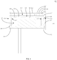
FIG. 1 is a schematic diagram illustrating a connecting structure of a pneumatic sensor according to the invention; -
FIG. 2 is a partial enlarged schematic diagram illustrating part A shown inFIG. 1 according to the invention; -
FIG. 3 is an exploded schematic diagram illustrating a connecting structure of a pneumatic sensor according to the invention; -
FIG. 4 is a cross-sectional schematic diagram illustrating a connecting structure of a pneumatic sensor according to another embodiment of the invention; -
FIG. 5 is a cross-sectional schematic diagram illustrating a connecting structure of an electronic cigarette according to the invention. - The implementation of aims, the function features and the advantages of the present disclosure are described below in further detail in conjunction with embodiments with reference to the drawings.
- A clear and complete description as below is provided for the technical solution in the embodiments of the invention in conjunction with the drawings in the embodiments of the invention. Obviously, the embodiments described hereinafter are simply part embodiments of the invention, rather than all the embodiments. All other embodiments obtained by those skilled in the art based on the embodiments in the invention without creative work are intended to be included in the scope of protection of the invention.
- It should be noted that all directional indications (such as top, bottom, left, right, front, behind...) in the embodiments of the invention are merely to illustrate a relative position relation, a relative motion condition, etc. between each part in a certain state (for example, the state shown in the drawings). If the state changes, the directional indication changes accordingly.
- In addition, if terms "first", "second", etc. appear in the invention, they are merely for the purpose of description, but cannot be understood as the indication or implication of relative importance or as the implicit indication of the number of the designated technical features; therefore, features defined by "first" and "second" may specifically or implicitly comprise at least one such feature. In addition, technical solutions of each embodiment of the invention may be combined mutually; however, this must be carried out on the basis that those skilled in the art can implement the combination. When the combination of technical solutions has a conflict or cannot be implemented, it should be considered that such combination of technical solutions does not exist and is not in the scope of protection claimed by the invention.
- In the invention, unless otherwise specifically stated and defined, terms "connected", "fixed", etc. should be interpreted expansively. For example, "fixed" may be fixed connection, detachable connection, or integration; may be mechanical connection or electrical connection; direct connection, indirect connection through an intermediate, or internal communication between two elements or interaction of two elements, unless otherwise specifically defined. Those skilled in the art can understand the specific implication of the above terms in the invention according to specific conditions.
- The invention provides a
pneumatic sensor 100, which is applied to anelectronic cigarette 1000 or other devices triggered by sensing a change in airflow. The invention takes theelectronic cigarette 1000 as an example. Theelectronic cigarette 1000 comprises anatomizer 300 pre-charged with tobacco liquid and acontroller 200 for powering theatomizer 300. Thepneumatic sensor 100 is mounted in thecontroller 200; and theatomizer 300 is mounted in thecontroller 200 and forms anairflow passage 330 with thecontroller 200. Thepneumatic sensor 100 senses a change in airflow within theairflow passage 330 and transmits a signal to thecontroller 200 to control theatomizer 300 to atomize the pre-stored tobacco liquid so as to generate smoke for user to smoke. - Referring to
FIG. 1 to FIG. 5 , thepneumatic sensor 100 comprises amain body 10, a trigger component 30 and a waterproof andbreathable membrane 50, wherein themain body 10 is provided with an internal cavity and at least one suction hole111 communicated with the internal cavity, the waterproof andbreathable membrane 50 is mounted in themain body 10 and covers each of thesuction holes 111, and the triggering component 30 is mounted in the internal cavity and is triggered when the airflow is sucked from thesuction hole 111 to the outside. - The
pneumatic sensor 100 according to the technical solution of the invention removes the dust cloth covering thesuction holes 111 in theconventional air sensor 100 so as to effectively prevent the phenomenon that the tobacco liquid and the condensed water are absorbed by the dust cloth so that it is difficult to clean; and then a waterproof and breathable membrane is provided 50 to cover each of thesuction holes 111. The waterproof andbreathable membrane 50 can be used for normal circulation of airflow, without affecting the original working performance of thepneumatic sensor 100. At the same time, it is effective to prevent the phenomenon that the tobacco liquid and the condensed water are accumulated in the suction hotel 11 during long-term use and are penetrated into thepneumatic sensor 100 from thesuction hole 111, thereby causing damage to the trigger component 30. - Further, as shown in
FIG. 2 , in the embodiment of the invention, the waterproof andbreathable membrane 50 comprises ananti-wrinkle ring 52 and asubstrate 51 having waterproof and breathable property, wherein theanti-wrinkle ring 52 covers the edge of thesubstrate 51 so that when thesubstrate 51 is mounted in themain body 10, the middle part of the substrate 51which does not cover the anti-wrinkle ring 52coverseach of thesuction holes 111, and forms abreathable part 511, and thebreathable part 511 is communicated with thesuction hole 111 through an air channel. Here, in the present embodiment, thesubstrate 51 is formed by hot-melting a high-performance composite material, such as a TPU waterproof andbreathable membrane 50, an EPTFE composite fabric, etc. The better waterproof and breathable property enables water vapor to pass freely, and at the same time, the condensed water dew is prevented from being penetrated into themain body 10 along thesuction hole 111, thereby causing damage to the trigger component 30; at the same time, in order to ensure better breathable property, the thickness of thesubstrate 51 is preferably in the range of 0.02 mm to 0.11 mm, and is more preferably 0.06 mm in the present embodiment. Further, in order to prevent thesubstrate 51 from deforming and wrinkling during the movement of airflow, in the present embodiment, a hardanti-wrinkle ring 52 is covered on the edge of thesubstrate 51. Theanti-wrinkle ring 52 may be selected from polymeric materials such as polyethylene terephthalate, polyethylene plastics, polypropylene plastics, fluoroplastics, polyvinyl chloride, and polyperfluoroethylene propylene. In the present embodiment, theanti-wrinkle ring 52 is prepared using polyethylene terephthalate, and is fixed to thesubstrate 51 by gluing, so that thesubstrate 51 has a certain tension to avoid wrinkles. At the same time, thesubstrate 51 not covered by theanti-wrinkle ring 52 forms abreathable part 511 through which the air in thesuction hole 111 flows out. - Further, as shown in
FIG. 2 , in the embodiment of the invention, the waterproof andbreathable membrane 50 further comprises anadhesive layer 53, theadhesive layer 53 is provided on the surface of thesubstrate 51 far away from theanti-wrinkle ring 52 so that thesubstrate 51 is adhered to themain body 10, and theadhesive layer 53 is provided to avoid the breathable part511 of thesubstrate 51. Here, in the present embodiment, theadhesive layer 53 is provided on the surface of thesubstrate 51 far away from theanti-wrinkle ring 52. When thesubstrate 51 is adhered to themain body 10, thehard wrinkle ring 52 protrudes from the outside, effectively preventing the phenomenon of abrasion and breakage of thesubstrate 51. - It is to be understood that in practical applications, the
adhesive layer 53 is not limited to being provided on the surface of thesubstrate 51 far away from theanti-wrinkle ring 52 as described above. For example, the manner in which the adhesive layer 53may be also provided on the outer surface of themain body 10 or provided on the surface of theanti-wrinkle ring 52 far away from thesubstrate 51 so as to fix thesubstrate 51 to themain body 10 falls within the scope of protection of the invention. - Specifically, as shown in
FIG. 3 , in the embodiment of the invention, the trigger component 30 comprises acircuit board 31, a firstconductive member 32, a secondconductive member 33 and atrigger diaphragm 34 which are housed in the internal cavity, the firstconductive member 32 and the secondconductive member 33 are both electrically connected to thecircuit board 31, thetrigger diaphragm 34 is electrically connected to the firstconductive member 32; when the airflow is sucked from thesuction hole 111 through the waterproof andbreathable membrane 50 to the outside, thetrigger diaphragm 34 partially vibrates until being in contact with the secondconductive member 33 to establish an electrical connection so that the firstconductive member 32 is communicated with the secondconductive member 33 through a circuit. Here, in the present embodiment, the firstconductive member 32 and the secondconductive member 33 are both stably and electrically connected to thecircuit board 31. Thetrigger diaphragm 34 is provided between the firstconductive member 32 and the secondconductive members 33 and is electrically connected to the firstconductive member 32. When the user smokes, and when the airflow inside themain body 10 is drawn out from thesuction hole 111, an air pressure difference is formed between the inside and the outside of themain body 10, thereby driving thetrigger diaphragm 34 to vibrate. When thetrigger diaphragm 34 vibrates until being in contact with the secondconductive member 33, the secondconductive member 33 and the firstconductive member 32 are electrically communicated. Both the firstconductive member 32 and the secondconductive member 33 are electrically communicated with thecircuit board 31 after the firstconductive member 32 and the secondconductive member 33 are connected in parallel. At this time, the total resistance value of thecircuit board 31 connected to the load is changed, thereby triggering thecircuit board 31 to transmit a corresponding control command to thecontroller 200 of theelectronic cigarette 1000. When the user stops smoking, the air pressure difference is restored, thetrigger diaphragm 34 is separated from the secondconductive member 33, the total resistance value of thecircuit board 31 connected to the load is restored to the original value, and thecircuit board 31 stops transmitting the control command to thecontroller 200 of theelectronic cigarette 1000. - Further, as shown in
FIG. 2 orFIG. 3 , in the embodiment of the invention, the trigger component 30 further comprises an annular insulatingmember 35, the firstconductive member 32 has a hollow tubular shape, both ends of the firstconductive member 32 are abutted with thecircuit board 31 and thetrigger diaphragm 34, respectively, so that the inside of the firstconductive member 32 encircles anair collecting space 342, the insulatingmember 35 is provided between the secondconductive member 33 and thetrigger diaphragm 34 so that the secondconductive member 33 is spaced apart from thetrigger diaphragm 34 to form aninternal cavity 341, the hollow portion of the second conductive member 33corresponding to the insulating member 35is further provided with at least oneair passing hole 331, and theair passing hole 331 is communicated with thecavity 341 and thesuction hole 111. Here, in the present embodiment, the firstconductive member 32 has a hollow tubular shape. The end of the firstconductive member 32 is fit with thecircuit board 31 to block the inner space of the tubular body, and is electrically connected to thecircuit board 31. Thetrigger diaphragm 34 covers the end of the firstconductive member 32 far away from thecircuit board 31, so that the inner space of the firstconductive member 32 encircles a closedair collecting space 342. The secondconductive member 33 has a plate shape to tightly press the insulatingmember 35 against the surface of the trigger diaphragm34 far away from the firstconductive member 32 to prevent the phenomenon that thetrigger diaphragm 34 shakes and falls off. At the same time, the inner diameter of the annular insulatingmember 35 is hollow so that there is a gap between the secondconductive member 33 and thetrigger diaphragm 34 to form thecavity 341. The secondconductive member 33 is provided with a plurality of air passing holes 331. The plurality ofair passing holes 331 and the suction holes 111 are electrically connected through an air channel, and the sum of the venting areas of the plurality ofair passing holes 331 is smaller than the sum of the venting areas of the suction holes 111. When the user smokes, the airflow in the internal cavity is extracted from the plurality of air passing holes 331. Moreover, since the air in theair collecting space 342 cannot be discharged due to being blocked by thetrigger diaphragm 34, the air pressure difference is generated to push thetrigger diaphragm 34 to move toward theair passing holes 331 so as to establish an electrical connection when moved until being in contact with the secondconductive member 33. When the user stops smoking, the outside airflow enters the internal cavity through theair passing holes 331, thereby eliminating the air pressure difference. - Further, as shown in
FIG. 1 , in the embodiment of the invention, thecircuit board 31 is further provided with at least oneair inlet hole 311, and theair inlet hole 311 is communicated with theair collecting space 342 and the outside. Here, in the present embodiment, thecircuit board 31 is provided with two air inlet holes 311. When the user smokes, the outside airflow may enter theair collecting space 342 from the two air inlet holes 311, and the volume of theair collecting space 342 changed due to the deformation of thetrigger diaphragm 34 is supplemented, so that it is easier to push thetrigger diaphragm 34 to move toward the secondconductive member 33. - It is to be understood that, in practical applications, the
air inlet hole 311 is not limited to being formed in thecircuit board 31 as described above. For example, as shown inFIG. 4 , in another embodiment of the invention, the manner in which the air inlet hole 311' may be also provided with a throughhole 131 formed by the firstconductive member 32 and a plurality of air inlet holes 311' are formed through themain body 10 to be communicated with the throughhole 131 to achieve air supply in theair collecting space 342 falls also within the scope of protection of the invention. - Specifically, the sum of the venting areas of the
air passing holes 331 is greater than the sum of the venting areas of the air inlet holes 311. Here, in the present embodiment, the total venting area of the plurality ofair passing holes 331 is greater than the total venting area of the plurality of air inlet holes 311, so that the total amount of air flowing out of the internal cavity per unit time is greater than the total amount of air entering theair collecting space 342 from the air inlet, ensuring the formation of the air pressure difference. - Specifically, as shown in
FIG. 1 , in the embodiment of the invention, themain body 10 comprises a top plate 11, abottom plate 12 and a connectingplate 13 connecting the top plate 11 and thebottom plate 12, the top plate 11, thebottom plate 12 and the connectingplate 13 encircle the internal cavity, the top plate 11 and thebottom plate 12 clamp opposite surfaces of the secondconductive member 33 and thecircuit board 31, the connectingplate 13 is spaced apart from the firstconductive member 32, and the top plate 11 is provided with thesuction hole 111. Here, in the present embodiment, themain body 10 is made of a conductive material. The top plate 11 clamps the secondconductive member 33 and establishes an electrical connection with the secondconductive member 33, and then is electrically connected to thecircuit board 31 through the connectingplate 13 and thebottom plate 12. At the same time, thebottom plate 12 is provided with awindow 121 to expose a part of the surface of thecircuit board 31 for theair inlet hole 311 to be communicated with the outside. - Further, as shown in
FIG. 1 , in the embodiment of the invention, aninsulator 36 is further provided between the connectingplate 13 and the firstconductive member 32. Here, in the present embodiment, the outer diameter value of the plate-shaped secondconductive member 33 is larger than the outer diameter value of the end of the tubular-shaped firstconductive member 32, so that a gap is formed between the connectingplate 13 and the firstconductive member 32 to prevent the phenomenon that the direct contact between the connectingplate 13 and the firstconductive member 32 enables the secondconductive member 33 and the firstconductive member 32 to be electrically communicated. At the same time, aninsulator 36 is provided in the gap there between to further prevent the firstconductive member 32 from shaking into direct contact with the connectingplate 13 during long-term use, so that the firstconductive member 32 and the secondconductive member 33 are electrically communicated, resulting in the phenomenon of false triggering. - Referring to
FIG. 5 , the invention further provides anelectronic cigarette 1000. Theelectronic cigarette 1000 comprises apneumatic sensor 100. Theelectronic cigarette 1000 executes the corresponding command when sensing that thepneumatic sensor 100 is triggered. Refer to the above embodiment for the specific structure of thepneumatic sensor 100. Due to the use of all the technical solutions of all the above embodiments, theelectronic cigarette 1000 has at least all the beneficial effects brought by the technical solutions of the above embodiments, which will not be described in detail herein. - As shown in
FIG. 5 , in the embodiment of the invention, theelectronic cigarette 1000 comprises anatomizer 300 and acontroller 200. Thecontroller 200 is provided with amain control board 210 and a receiving chamber with an opening. Theatomizer 300 comprises anatomizing component 310 and ahousing 320 covering theatomizing component 310. One end of thehousing 320 is inserted in the receiving chamber and anairflow passage 330 is formed between the end of thehousing 320 and the internal cavity wall of the receiving chamber. Theatomizing component 310 is electrically connected to themain control board 210 when thehousing 320 is inserted into the receiving cavity, and forms anoil storage chamber 340 with thehousing 320. The air inlet end of theatomizer 300 is communicated with theairflow passage 330, and the air outlet end thereof is communicated with the outside through thehousing 320. Theairflow passage 330 is mounted with thepneumatic sensor 100 as described above. Thepneumatic sensor 100 triggers to transmit a control signal to themain control board 210 when the airflow in theairflow passage 330 is extracted at a high speed, driving themain control board 210 to supply power to theatomizing component 310 so that theatomizing component 310 heats the internally stored tobacco liquid to generate smoke for the user to smoke. - The above are preferred embodiments of the invention merely and are not intended to limit the patent scope of the invention. Any equivalent structures made according to the description and the accompanying drawings of the invention without departing from the idea of the invention, or any equivalent structures applied in other relevant technical fields directly or indirectly are intended to be included in the patent protection scope of the invention.
| Reference number | Name of part | Reference number | Name of |
| 100 | | 342 | |
| 10 | | 35 | insulating member |
| 11 | | 36 | |
| 111 | | 50 | waterproof and |
| 12 | | 51 | |
| 121 | | 511 | |
| 13 | connecting | 52 | |
| 131 | through | 53 | adhesive layer |
| 30 | | 200 | |
| 31 | | 210 | |
| 311 | | 300 | |
| 32 | first | 310 | atomizing component |
| 321' | | 320 | |
| 33 | second | 330 | |
| 331 | | 340 | |
| 34 | | 1000 | |
| 341 | cavity |
Claims (10)
- A pneumatic sensor comprising a main body (10), a trigger component (30) and a waterproof and breathable membrane (50), wherein the main body (10) is provided with an internal cavity and at least one suction hole (111)communicated with the internal cavity, the waterproof and breathable membrane (50) is mounted in the main body (10) and covers each of the at least one suction hole (111), and the triggering component (30) is mounted in the internal cavity and is triggered when the airflow is sucked from the suction hole (111) to outside.
- The pneumatic sensor according to claim 1, wherein the waterproof and breathable membrane (50) comprises an anti-wrinkle ring (52) and a substrate (51) having waterproof and breathable property, the anti-wrinkle ring (52) covers the edge of the substrate (51) so that when the substrate (51) is mounted in the main body (10), a middle part of the substrate (51) which does not cover the anti-wrinkle ring (52) covers each of the at least one suction hole (111), and forms a breathable part (511), and the breathable part (511) is communicated with the suction hole (111) through an air channel.
- The pneumatic sensor according to claim 2, wherein the waterproof and breathable membrane (50) further comprises an adhesive layer (53), the adhesive layer (53) is provided on a surface of the substrate (51) far away from the anti-wrinkle ring (52) so that the substrate (51) is adhered to the main body (10), and the adhesive layer (53) is provided to avoid the breathable part (511) of the substrate (51); and/or, the substrate (51) has a thickness value in a range from0.02 mm to 0.11 mm.
- The pneumatic sensor according to any one of claims 1 to 3, wherein the trigger component (30) comprises a circuit board (31), a first conductive member (32), a second conductive member (33) and a trigger diaphragm (34) which are housed in the internal cavity, the first conductive member (32) and the second conductive member (33) are both electrically connected to the circuit board (31), the trigger diaphragm (34) is electrically connected to the first conductive member (32); when the airflow is sucked from the at least one suction hole (111) through the waterproof and breathable membrane (50) to the outside, the trigger diaphragm (34) partially vibrates until being in contact with the second conductive member (33) to establish an electrical connection, so that the first conductive member (32) is communicated with the second conductive member (33) through a circuit.
- The pneumatic sensor according to claim 4, wherein the trigger component (30) further comprises an annular insulating member (35), the first conductive member (32) has a hollow tubular shape, both ends of the first conductive member (32) abut against the circuit board (31) and the trigger diaphragm (34), respectively, so that the inside of the first conductive member (32) encircles an air collecting space (342), the insulating member (35) is provided between the second conductive member (33) and the trigger diaphragm (34) so that the second conductive member (33) is spaced apart from the trigger diaphragm (34), the hollow portion of the second conductive member (33) corresponding to the insulating member (35) is further provided with at least one air passing hole (331), and the air passing hole (331) is communicated with the cavity (341) and the suction hole (111).
- The pneumatic sensor according to claim 5, wherein the circuit board (31) is further provided with at least one air inlet hole (311), and the at least one air inlet hole (311) is communicated with the air collecting space (342) and the outside.
- The pneumatic sensor according to claim 6, wherein the sum of the venting areas of the air passing holes (331) is greater than the sum of the venting areas of the air inlet holes (311).
- The pneumatic sensor according to claim 5, wherein the main body (10) comprises a top plate (11), a bottom plate (12) and a connecting plate (13) connecting the top plate (11) and the bottom plate (12), the top plate (11), the bottom plate (12) and the connecting plate (13) encircle the internal cavity, the top plate (11) and the bottom plate (12) clamp opposite surfaces of the second conductive member (33) and the circuit board (31), the connecting plate (13) is spaced apart from the first conductive member (32), and the top plate (11) is provided with the suction hole (111).
- The pneumatic sensor according to claim 8, wherein an insulator (36) is further provided between the connecting plate (13) and the first conductive member (32).
- An electronic cigarette, comprising the pneumatic sensor (100) according to any one of claims 1 to 9, wherein the electronic cigarette (1000) is configured for executing the corresponding command when sensing that the pneumatic sensor (100) is triggered.
Applications Claiming Priority (1)
| Application Number | Priority Date | Filing Date | Title |
|---|---|---|---|
| CN201821063423.8U CN208676373U (en) | 2018-07-05 | 2018-07-05 | Pneumatic transmitter and electronic cigarette |
Publications (2)
| Publication Number | Publication Date |
|---|---|
| EP3590363A1 true EP3590363A1 (en) | 2020-01-08 |
| EP3590363B1 EP3590363B1 (en) | 2022-08-10 |
Family
ID=63713766
Family Applications (1)
| Application Number | Title | Priority Date | Filing Date |
|---|---|---|---|
| EP18197832.1A Active EP3590363B1 (en) | 2018-07-05 | 2018-10-01 | Pneumatic sensor and electronic cigarette having same |
Country Status (5)
| Country | Link |
|---|---|
| US (1) | US11844376B2 (en) |
| EP (1) | EP3590363B1 (en) |
| CN (1) | CN208676373U (en) |
| CA (1) | CA3020121C (en) |
| DE (1) | DE202018006603U1 (en) |
Cited By (4)
| Publication number | Priority date | Publication date | Assignee | Title |
|---|---|---|---|---|
| EP3742465A1 (en) * | 2019-05-16 | 2020-11-25 | Shenzhen IVPS Technology Co., Ltd. | An air pressure switch, power supply device and e-cigarettes containing the same |
| WO2022034087A1 (en) * | 2020-08-10 | 2022-02-17 | Jt International S.A. | Aerosol generation device comprising a pressure capture assembly and associated assembly method |
| WO2023043596A1 (en) * | 2021-09-17 | 2023-03-23 | Invensense, Inc. | WATERPROOF MEMS PRESSURE SENSOR PACKAGE WITH A METAL LID AND AN EMBEDDED ePTFE FILTER AND PROCESS OF MAKING |
| US12428292B2 (en) | 2021-09-17 | 2025-09-30 | Invensense, Inc. | Waterproof mems pressure sensor package with a metal lid and an embedded ePTFE filter and process of making |
Families Citing this family (10)
| Publication number | Priority date | Publication date | Assignee | Title |
|---|---|---|---|---|
| CN111602858A (en) * | 2019-05-16 | 2020-09-01 | 深圳市艾维普思科技有限公司 | Pneumatic switch of electronic cigarette, power supply device of electronic cigarette and electronic cigarette |
| CN111602857A (en) * | 2019-05-16 | 2020-09-01 | 深圳市艾维普思科技有限公司 | Pneumatic switch of electronic cigarette, power supply device of electronic cigarette and electronic cigarette |
| CN111588092A (en) * | 2019-05-16 | 2020-08-28 | 深圳市艾维普思科技有限公司 | Waterproof construction and electron cigarette of electron cigarette pneumatic switch |
| CN111602859A (en) * | 2019-06-29 | 2020-09-01 | 深圳市艾维普思科技有限公司 | an electronic cigarette |
| WO2021003641A1 (en) * | 2019-07-08 | 2021-01-14 | 昂纳自动化技术(深圳)有限公司 | Electronic cigarette and airflow switch bracket, airflow switch assembly and power supply apparatus thereof |
| CN110507007A (en) * | 2019-09-30 | 2019-11-29 | 深圳市合元科技有限公司 | Gas flow transducer and electronic cigarette |
| CN211065067U (en) * | 2019-09-30 | 2020-07-24 | 深圳市合元科技有限公司 | Airflow sensor and electronic cigarette |
| WO2021158758A1 (en) | 2020-02-04 | 2021-08-12 | Juul Labs, Inc. | Aerosol dispensing device with disposable container |
| JP7767443B2 (en) * | 2021-07-29 | 2025-11-11 | ケーティー アンド ジー コーポレイション | Heat insulating material for aerosol generating device and aerosol generating device including the same |
| CN115813045A (en) * | 2022-12-15 | 2023-03-21 | 深圳市艾维普思科技有限公司 | An aerosol generator and a child lock control method for the aerosol generator |
Citations (5)
| Publication number | Priority date | Publication date | Assignee | Title |
|---|---|---|---|---|
| US5404891A (en) * | 1993-03-31 | 1995-04-11 | Taijiro Ishikawa | Automatically extinguishable cigarette |
| WO2014144678A2 (en) * | 2013-03-15 | 2014-09-18 | Lewis Michael W | Electronic smoking device systems and methods |
| CN204540828U (en) * | 2015-03-23 | 2015-08-12 | 纳米新能源(唐山)有限责任公司 | Diaphragm type pneumatic transmitter, airflow treatment device and electronic cigarette |
| CN204556034U (en) * | 2015-03-30 | 2015-08-12 | 纳米新能源(唐山)有限责任公司 | Electronic cigarette pneumatic transmitter, airflow treatment device and electronic cigarette |
| CN107890142A (en) * | 2017-12-22 | 2018-04-10 | 深圳市艾维普思科技有限公司 | Electronic cigarette |
Family Cites Families (19)
| Publication number | Priority date | Publication date | Assignee | Title |
|---|---|---|---|---|
| CN100381083C (en) * | 2003-04-29 | 2008-04-16 | 韩力 | Non-combustible electronic spray cigarette |
| CN2719043Y (en) * | 2004-04-14 | 2005-08-24 | 韩力 | Atomized electronic cigarette |
| CN101606758B (en) * | 2009-07-14 | 2011-04-13 | 方晓林 | Electronic cigarette |
| US9562873B2 (en) * | 2011-10-14 | 2017-02-07 | Msa Technology, Llc | Sensor interrogation |
| JP6420155B2 (en) * | 2012-02-22 | 2018-11-07 | アルトリア クライアント サービシーズ エルエルシー | Electronic smoking article and improved heater element |
| US9714878B2 (en) * | 2013-09-12 | 2017-07-25 | Arrow Electronics, Inc. | Pressure sensitive device for flow detection |
| CN203646510U (en) * | 2013-12-30 | 2014-06-18 | 刘秋明 | Electronic cigarette, and battery rod and atomizer thereof |
| US9750282B2 (en) * | 2014-09-12 | 2017-09-05 | Shenzhen Smoore Technology Limited | Electronic cigarette and air switch thereof |
| CN106136321B (en) | 2015-03-23 | 2018-11-20 | 纳米新能源(唐山)有限责任公司 | Diaphragm type pneumatic transmitter, airflow treatment device and electronic cigarette |
| CN105433439B (en) | 2015-07-28 | 2018-06-12 | 纳智源科技(唐山)有限责任公司 | Electronic cigarette pneumatic transmitter, airflow treatment device and electronic cigarette |
| US10034494B2 (en) * | 2015-09-15 | 2018-07-31 | Rai Strategic Holdings, Inc. | Reservoir for aerosol delivery devices |
| US10132706B2 (en) * | 2015-09-28 | 2018-11-20 | Apple Inc. | Waterproof barometric sensor in an electronic device |
| US11433211B2 (en) * | 2016-03-17 | 2022-09-06 | Zoll Medical Corporation | Flow sensor for ventilation |
| GB2555829B (en) * | 2016-11-11 | 2019-11-20 | Sensata Technologies Inc | Encapsulations for MEMS sense elements and wire bonds |
| CN108720085A (en) * | 2017-04-24 | 2018-11-02 | 深圳赛睿微生物新能源有限公司 | Electronic cigarette, the control method of electronic cigarette and storage medium |
| TWI644626B (en) * | 2017-06-14 | 2018-12-21 | 研能科技股份有限公司 | Driving module of electronic cigarette |
| CN109181567A (en) * | 2018-09-27 | 2019-01-11 | 崔福文 | Breathable sound-transmitting waterproof membrane laminated structure and its auxiliary support |
| CN209314969U (en) * | 2018-11-23 | 2019-08-30 | 上海新型烟草制品研究院有限公司 | A liquid storage device and an aerosol generating device |
| CN214179145U (en) * | 2020-12-21 | 2021-09-14 | 烟台耐沃新材料有限公司 | Airflow sensor |
-
2018
- 2018-07-05 CN CN201821063423.8U patent/CN208676373U/en active Active
- 2018-10-01 US US16/148,878 patent/US11844376B2/en active Active
- 2018-10-01 DE DE202018006603.6U patent/DE202018006603U1/en not_active Expired - Lifetime
- 2018-10-01 EP EP18197832.1A patent/EP3590363B1/en active Active
- 2018-10-09 CA CA3020121A patent/CA3020121C/en active Active
Patent Citations (5)
| Publication number | Priority date | Publication date | Assignee | Title |
|---|---|---|---|---|
| US5404891A (en) * | 1993-03-31 | 1995-04-11 | Taijiro Ishikawa | Automatically extinguishable cigarette |
| WO2014144678A2 (en) * | 2013-03-15 | 2014-09-18 | Lewis Michael W | Electronic smoking device systems and methods |
| CN204540828U (en) * | 2015-03-23 | 2015-08-12 | 纳米新能源(唐山)有限责任公司 | Diaphragm type pneumatic transmitter, airflow treatment device and electronic cigarette |
| CN204556034U (en) * | 2015-03-30 | 2015-08-12 | 纳米新能源(唐山)有限责任公司 | Electronic cigarette pneumatic transmitter, airflow treatment device and electronic cigarette |
| CN107890142A (en) * | 2017-12-22 | 2018-04-10 | 深圳市艾维普思科技有限公司 | Electronic cigarette |
Cited By (5)
| Publication number | Priority date | Publication date | Assignee | Title |
|---|---|---|---|---|
| EP3742465A1 (en) * | 2019-05-16 | 2020-11-25 | Shenzhen IVPS Technology Co., Ltd. | An air pressure switch, power supply device and e-cigarettes containing the same |
| WO2022034087A1 (en) * | 2020-08-10 | 2022-02-17 | Jt International S.A. | Aerosol generation device comprising a pressure capture assembly and associated assembly method |
| US12501939B2 (en) | 2020-08-10 | 2025-12-23 | Jt International Sa | Aerosol generation device comprising a pressure capture assembly and associated assembly method |
| WO2023043596A1 (en) * | 2021-09-17 | 2023-03-23 | Invensense, Inc. | WATERPROOF MEMS PRESSURE SENSOR PACKAGE WITH A METAL LID AND AN EMBEDDED ePTFE FILTER AND PROCESS OF MAKING |
| US12428292B2 (en) | 2021-09-17 | 2025-09-30 | Invensense, Inc. | Waterproof mems pressure sensor package with a metal lid and an embedded ePTFE filter and process of making |
Also Published As
| Publication number | Publication date |
|---|---|
| US11844376B2 (en) | 2023-12-19 |
| EP3590363B1 (en) | 2022-08-10 |
| CA3020121C (en) | 2021-06-22 |
| CA3020121A1 (en) | 2020-01-05 |
| DE202018006603U1 (en) | 2021-06-14 |
| US20200011756A1 (en) | 2020-01-09 |
| CN208676373U (en) | 2019-04-02 |
Similar Documents
| Publication | Publication Date | Title |
|---|---|---|
| EP3590363B1 (en) | Pneumatic sensor and electronic cigarette having same | |
| US11064740B2 (en) | Power supply and electronic cigarette having same | |
| EP3590368B1 (en) | Power assembly and electronic cigarette having same | |
| EP4039114B1 (en) | Air flow sensor and electronic cigarette | |
| US9714878B2 (en) | Pressure sensitive device for flow detection | |
| JP5864745B2 (en) | Electronic smoking device | |
| US11213071B2 (en) | Electronic cigarette | |
| EP3742465B1 (en) | An air pressure switch, power supply device and e-cigarettes containing the same | |
| EP3850963A1 (en) | Electronic atomization device and atomizer | |
| ITMI951717A1 (en) | ULTRASONIC AEROSOL APPARATUS | |
| CN105476069A (en) | Capacitive sensor, device using capacitive sensor and method for using capacitive sensor | |
| CN116268632A (en) | Air flow sensor, electronic atomizer and control method thereof | |
| WO2025112767A1 (en) | Electronic cigarette having high sensitivity | |
| CN222109269U (en) | Aerosol generating device | |
| CN210642440U (en) | Waterproof construction and electron cigarette of electron cigarette pneumatic switch | |
| CN111588092A (en) | Waterproof construction and electron cigarette of electron cigarette pneumatic switch | |
| CN111602857A (en) | Pneumatic switch of electronic cigarette, power supply device of electronic cigarette and electronic cigarette | |
| CN111602858A (en) | Pneumatic switch of electronic cigarette, power supply device of electronic cigarette and electronic cigarette | |
| CN222917035U (en) | Resistance type air flow switch and automatic electronic atomizer | |
| CN221142190U (en) | Atomizing device and clothes treatment equipment | |
| CN221284687U (en) | Aerosol generating device | |
| JPH08238201A (en) | Electric vacuum cleaner and nozzle therefor | |
| CN115191675B (en) | Power supply unit and electronic atomization device | |
| CN211505312U (en) | Airflow sensor | |
| CN119523170A (en) | Vaping devices and e-cigarettes |
Legal Events
| Date | Code | Title | Description |
|---|---|---|---|
| REG | Reference to a national code |
Ref country code: DE Ref legal event code: R138 Ref document number: 202018006603 Country of ref document: DE Free format text: GERMAN DOCUMENT NUMBER IS 602018039010 |
|
| PUAI | Public reference made under article 153(3) epc to a published international application that has entered the european phase |
Free format text: ORIGINAL CODE: 0009012 |
|
| STAA | Information on the status of an ep patent application or granted ep patent |
Free format text: STATUS: REQUEST FOR EXAMINATION WAS MADE |
|
| 17P | Request for examination filed |
Effective date: 20181029 |
|
| AK | Designated contracting states |
Kind code of ref document: A1 Designated state(s): AL AT BE BG CH CY CZ DE DK EE ES FI FR GB GR HR HU IE IS IT LI LT LU LV MC MK MT NL NO PL PT RO RS SE SI SK SM TR |
|
| AX | Request for extension of the european patent |
Extension state: BA ME |
|
| GRAP | Despatch of communication of intention to grant a patent |
Free format text: ORIGINAL CODE: EPIDOSNIGR1 |
|
| STAA | Information on the status of an ep patent application or granted ep patent |
Free format text: STATUS: GRANT OF PATENT IS INTENDED |
|
| INTG | Intention to grant announced |
Effective date: 20200511 |
|
| GRAS | Grant fee paid |
Free format text: ORIGINAL CODE: EPIDOSNIGR3 |
|
| GRAA | (expected) grant |
Free format text: ORIGINAL CODE: 0009210 |
|
| STAA | Information on the status of an ep patent application or granted ep patent |
Free format text: STATUS: THE PATENT HAS BEEN GRANTED |
|
| AK | Designated contracting states |
Kind code of ref document: B1 Designated state(s): AL AT BE BG CH CY CZ DE DK EE ES FI FR GB GR HR HU IE IS IT LI LT LU LV MC MK MT NL NO PL PT RO RS SE SI SK SM TR |
|
| REG | Reference to a national code |
Ref country code: AT Ref legal event code: REF Ref document number: 1509867 Country of ref document: AT Kind code of ref document: T Effective date: 20220815 Ref country code: CH Ref legal event code: EP |
|
| REG | Reference to a national code |
Ref country code: IE Ref legal event code: FG4D |
|
| REG | Reference to a national code |
Ref country code: DE Ref legal event code: R096 Ref document number: 602018039010 Country of ref document: DE |
|
| REG | Reference to a national code |
Ref country code: NL Ref legal event code: MP Effective date: 20220810 |
|
| REG | Reference to a national code |
Ref country code: LT Ref legal event code: MG9D |
|
| PG25 | Lapsed in a contracting state [announced via postgrant information from national office to epo] |
Ref country code: SE Free format text: LAPSE BECAUSE OF FAILURE TO SUBMIT A TRANSLATION OF THE DESCRIPTION OR TO PAY THE FEE WITHIN THE PRESCRIBED TIME-LIMIT Effective date: 20220810 Ref country code: RS Free format text: LAPSE BECAUSE OF FAILURE TO SUBMIT A TRANSLATION OF THE DESCRIPTION OR TO PAY THE FEE WITHIN THE PRESCRIBED TIME-LIMIT Effective date: 20220810 Ref country code: PT Free format text: LAPSE BECAUSE OF FAILURE TO SUBMIT A TRANSLATION OF THE DESCRIPTION OR TO PAY THE FEE WITHIN THE PRESCRIBED TIME-LIMIT Effective date: 20221212 Ref country code: NO Free format text: LAPSE BECAUSE OF FAILURE TO SUBMIT A TRANSLATION OF THE DESCRIPTION OR TO PAY THE FEE WITHIN THE PRESCRIBED TIME-LIMIT Effective date: 20221110 Ref country code: NL Free format text: LAPSE BECAUSE OF FAILURE TO SUBMIT A TRANSLATION OF THE DESCRIPTION OR TO PAY THE FEE WITHIN THE PRESCRIBED TIME-LIMIT Effective date: 20220810 Ref country code: LV Free format text: LAPSE BECAUSE OF FAILURE TO SUBMIT A TRANSLATION OF THE DESCRIPTION OR TO PAY THE FEE WITHIN THE PRESCRIBED TIME-LIMIT Effective date: 20220810 Ref country code: LT Free format text: LAPSE BECAUSE OF FAILURE TO SUBMIT A TRANSLATION OF THE DESCRIPTION OR TO PAY THE FEE WITHIN THE PRESCRIBED TIME-LIMIT Effective date: 20220810 Ref country code: FI Free format text: LAPSE BECAUSE OF FAILURE TO SUBMIT A TRANSLATION OF THE DESCRIPTION OR TO PAY THE FEE WITHIN THE PRESCRIBED TIME-LIMIT Effective date: 20220810 |
|
| REG | Reference to a national code |
Ref country code: AT Ref legal event code: MK05 Ref document number: 1509867 Country of ref document: AT Kind code of ref document: T Effective date: 20220810 |
|
| PG25 | Lapsed in a contracting state [announced via postgrant information from national office to epo] |
Ref country code: PL Free format text: LAPSE BECAUSE OF FAILURE TO SUBMIT A TRANSLATION OF THE DESCRIPTION OR TO PAY THE FEE WITHIN THE PRESCRIBED TIME-LIMIT Effective date: 20220810 Ref country code: IS Free format text: LAPSE BECAUSE OF FAILURE TO SUBMIT A TRANSLATION OF THE DESCRIPTION OR TO PAY THE FEE WITHIN THE PRESCRIBED TIME-LIMIT Effective date: 20221210 Ref country code: HR Free format text: LAPSE BECAUSE OF FAILURE TO SUBMIT A TRANSLATION OF THE DESCRIPTION OR TO PAY THE FEE WITHIN THE PRESCRIBED TIME-LIMIT Effective date: 20220810 Ref country code: GR Free format text: LAPSE BECAUSE OF FAILURE TO SUBMIT A TRANSLATION OF THE DESCRIPTION OR TO PAY THE FEE WITHIN THE PRESCRIBED TIME-LIMIT Effective date: 20221111 |
|
| PG25 | Lapsed in a contracting state [announced via postgrant information from national office to epo] |
Ref country code: SM Free format text: LAPSE BECAUSE OF FAILURE TO SUBMIT A TRANSLATION OF THE DESCRIPTION OR TO PAY THE FEE WITHIN THE PRESCRIBED TIME-LIMIT Effective date: 20220810 Ref country code: RO Free format text: LAPSE BECAUSE OF FAILURE TO SUBMIT A TRANSLATION OF THE DESCRIPTION OR TO PAY THE FEE WITHIN THE PRESCRIBED TIME-LIMIT Effective date: 20220810 Ref country code: ES Free format text: LAPSE BECAUSE OF FAILURE TO SUBMIT A TRANSLATION OF THE DESCRIPTION OR TO PAY THE FEE WITHIN THE PRESCRIBED TIME-LIMIT Effective date: 20220810 Ref country code: DK Free format text: LAPSE BECAUSE OF FAILURE TO SUBMIT A TRANSLATION OF THE DESCRIPTION OR TO PAY THE FEE WITHIN THE PRESCRIBED TIME-LIMIT Effective date: 20220810 Ref country code: CZ Free format text: LAPSE BECAUSE OF FAILURE TO SUBMIT A TRANSLATION OF THE DESCRIPTION OR TO PAY THE FEE WITHIN THE PRESCRIBED TIME-LIMIT Effective date: 20220810 Ref country code: AT Free format text: LAPSE BECAUSE OF FAILURE TO SUBMIT A TRANSLATION OF THE DESCRIPTION OR TO PAY THE FEE WITHIN THE PRESCRIBED TIME-LIMIT Effective date: 20220810 |
|
| REG | Reference to a national code |
Ref country code: DE Ref legal event code: R097 Ref document number: 602018039010 Country of ref document: DE |
|
| PG25 | Lapsed in a contracting state [announced via postgrant information from national office to epo] |
Ref country code: SK Free format text: LAPSE BECAUSE OF FAILURE TO SUBMIT A TRANSLATION OF THE DESCRIPTION OR TO PAY THE FEE WITHIN THE PRESCRIBED TIME-LIMIT Effective date: 20220810 Ref country code: MC Free format text: LAPSE BECAUSE OF FAILURE TO SUBMIT A TRANSLATION OF THE DESCRIPTION OR TO PAY THE FEE WITHIN THE PRESCRIBED TIME-LIMIT Effective date: 20220810 Ref country code: EE Free format text: LAPSE BECAUSE OF FAILURE TO SUBMIT A TRANSLATION OF THE DESCRIPTION OR TO PAY THE FEE WITHIN THE PRESCRIBED TIME-LIMIT Effective date: 20220810 |
|
| REG | Reference to a national code |
Ref country code: CH Ref legal event code: PL |
|
| PLBE | No opposition filed within time limit |
Free format text: ORIGINAL CODE: 0009261 |
|
| STAA | Information on the status of an ep patent application or granted ep patent |
Free format text: STATUS: NO OPPOSITION FILED WITHIN TIME LIMIT |
|
| REG | Reference to a national code |
Ref country code: BE Ref legal event code: MM Effective date: 20221031 |
|
| PG25 | Lapsed in a contracting state [announced via postgrant information from national office to epo] |
Ref country code: LU Free format text: LAPSE BECAUSE OF NON-PAYMENT OF DUE FEES Effective date: 20221001 Ref country code: AL Free format text: LAPSE BECAUSE OF FAILURE TO SUBMIT A TRANSLATION OF THE DESCRIPTION OR TO PAY THE FEE WITHIN THE PRESCRIBED TIME-LIMIT Effective date: 20220810 |
|
| 26N | No opposition filed |
Effective date: 20230511 |
|
| PG25 | Lapsed in a contracting state [announced via postgrant information from national office to epo] |
Ref country code: LI Free format text: LAPSE BECAUSE OF NON-PAYMENT OF DUE FEES Effective date: 20221031 Ref country code: CH Free format text: LAPSE BECAUSE OF NON-PAYMENT OF DUE FEES Effective date: 20221031 |
|
| PG25 | Lapsed in a contracting state [announced via postgrant information from national office to epo] |
Ref country code: SI Free format text: LAPSE BECAUSE OF FAILURE TO SUBMIT A TRANSLATION OF THE DESCRIPTION OR TO PAY THE FEE WITHIN THE PRESCRIBED TIME-LIMIT Effective date: 20220810 |
|
| PG25 | Lapsed in a contracting state [announced via postgrant information from national office to epo] |
Ref country code: BE Free format text: LAPSE BECAUSE OF NON-PAYMENT OF DUE FEES Effective date: 20221031 |
|
| PG25 | Lapsed in a contracting state [announced via postgrant information from national office to epo] |
Ref country code: IE Free format text: LAPSE BECAUSE OF NON-PAYMENT OF DUE FEES Effective date: 20221001 |
|
| PG25 | Lapsed in a contracting state [announced via postgrant information from national office to epo] |
Ref country code: HU Free format text: LAPSE BECAUSE OF FAILURE TO SUBMIT A TRANSLATION OF THE DESCRIPTION OR TO PAY THE FEE WITHIN THE PRESCRIBED TIME-LIMIT; INVALID AB INITIO Effective date: 20181001 |
|
| PG25 | Lapsed in a contracting state [announced via postgrant information from national office to epo] |
Ref country code: CY Free format text: LAPSE BECAUSE OF FAILURE TO SUBMIT A TRANSLATION OF THE DESCRIPTION OR TO PAY THE FEE WITHIN THE PRESCRIBED TIME-LIMIT Effective date: 20220810 |
|
| PG25 | Lapsed in a contracting state [announced via postgrant information from national office to epo] |
Ref country code: MK Free format text: LAPSE BECAUSE OF FAILURE TO SUBMIT A TRANSLATION OF THE DESCRIPTION OR TO PAY THE FEE WITHIN THE PRESCRIBED TIME-LIMIT Effective date: 20220810 Ref country code: IT Free format text: LAPSE BECAUSE OF FAILURE TO SUBMIT A TRANSLATION OF THE DESCRIPTION OR TO PAY THE FEE WITHIN THE PRESCRIBED TIME-LIMIT Effective date: 20220810 |
|
| PG25 | Lapsed in a contracting state [announced via postgrant information from national office to epo] |
Ref country code: TR Free format text: LAPSE BECAUSE OF FAILURE TO SUBMIT A TRANSLATION OF THE DESCRIPTION OR TO PAY THE FEE WITHIN THE PRESCRIBED TIME-LIMIT Effective date: 20220810 |
|
| PG25 | Lapsed in a contracting state [announced via postgrant information from national office to epo] |
Ref country code: BG Free format text: LAPSE BECAUSE OF FAILURE TO SUBMIT A TRANSLATION OF THE DESCRIPTION OR TO PAY THE FEE WITHIN THE PRESCRIBED TIME-LIMIT Effective date: 20220810 |
|
| PG25 | Lapsed in a contracting state [announced via postgrant information from national office to epo] |
Ref country code: MT Free format text: LAPSE BECAUSE OF FAILURE TO SUBMIT A TRANSLATION OF THE DESCRIPTION OR TO PAY THE FEE WITHIN THE PRESCRIBED TIME-LIMIT Effective date: 20220810 |
|
| PGFP | Annual fee paid to national office [announced via postgrant information from national office to epo] |
Ref country code: DE Payment date: 20251027 Year of fee payment: 8 |
|
| PGFP | Annual fee paid to national office [announced via postgrant information from national office to epo] |
Ref country code: GB Payment date: 20251030 Year of fee payment: 8 |
|
| PGFP | Annual fee paid to national office [announced via postgrant information from national office to epo] |
Ref country code: FR Payment date: 20251027 Year of fee payment: 8 |