EP3590327A1 - A baler - Google Patents
A baler Download PDFInfo
- Publication number
- EP3590327A1 EP3590327A1 EP19184365.5A EP19184365A EP3590327A1 EP 3590327 A1 EP3590327 A1 EP 3590327A1 EP 19184365 A EP19184365 A EP 19184365A EP 3590327 A1 EP3590327 A1 EP 3590327A1
- Authority
- EP
- European Patent Office
- Prior art keywords
- twine
- cradle
- baler
- spool
- intermediate position
- Prior art date
- Legal status (The legal status is an assumption and is not a legal conclusion. Google has not performed a legal analysis and makes no representation as to the accuracy of the status listed.)
- Granted
Links
Images



Classifications
-
- A—HUMAN NECESSITIES
- A01—AGRICULTURE; FORESTRY; ANIMAL HUSBANDRY; HUNTING; TRAPPING; FISHING
- A01F—PROCESSING OF HARVESTED PRODUCE; HAY OR STRAW PRESSES; DEVICES FOR STORING AGRICULTURAL OR HORTICULTURAL PRODUCE
- A01F15/00—Baling presses for straw, hay or the like
- A01F15/08—Details
- A01F15/14—Tying devices specially adapted for baling presses
- A01F15/145—Twine knotters
-
- A—HUMAN NECESSITIES
- A01—AGRICULTURE; FORESTRY; ANIMAL HUSBANDRY; HUNTING; TRAPPING; FISHING
- A01F—PROCESSING OF HARVESTED PRODUCE; HAY OR STRAW PRESSES; DEVICES FOR STORING AGRICULTURAL OR HORTICULTURAL PRODUCE
- A01F15/00—Baling presses for straw, hay or the like
- A01F15/08—Details
- A01F15/12—Feeding devices for the ties
-
- A—HUMAN NECESSITIES
- A01—AGRICULTURE; FORESTRY; ANIMAL HUSBANDRY; HUNTING; TRAPPING; FISHING
- A01F—PROCESSING OF HARVESTED PRODUCE; HAY OR STRAW PRESSES; DEVICES FOR STORING AGRICULTURAL OR HORTICULTURAL PRODUCE
- A01F21/00—Devices for protecting human beings for threshing machines or baling presses
-
- B—PERFORMING OPERATIONS; TRANSPORTING
- B65—CONVEYING; PACKING; STORING; HANDLING THIN OR FILAMENTARY MATERIAL
- B65B—MACHINES, APPARATUS OR DEVICES FOR, OR METHODS OF, PACKAGING ARTICLES OR MATERIALS; UNPACKING
- B65B27/00—Bundling particular articles presenting special problems using string, wire, or narrow tape or band; Baling fibrous material, e.g. peat, not otherwise provided for
- B65B27/12—Baling or bundling compressible fibrous material, e.g. peat
-
- Y—GENERAL TAGGING OF NEW TECHNOLOGICAL DEVELOPMENTS; GENERAL TAGGING OF CROSS-SECTIONAL TECHNOLOGIES SPANNING OVER SEVERAL SECTIONS OF THE IPC; TECHNICAL SUBJECTS COVERED BY FORMER USPC CROSS-REFERENCE ART COLLECTIONS [XRACs] AND DIGESTS
- Y10—TECHNICAL SUBJECTS COVERED BY FORMER USPC
- Y10S—TECHNICAL SUBJECTS COVERED BY FORMER USPC CROSS-REFERENCE ART COLLECTIONS [XRACs] AND DIGESTS
- Y10S100/00—Presses
- Y10S100/912—Binder containers
Definitions
- US 2012/0012012 A1 discloses a baler.
- the baler collects the harvested goods by means of collecting / pickup and conveying devices and supplies the collected harvested goods to a pressing device that forms the harvested goods into bales.
- the bales are tied by tying or binding material that is supplied to the bale from a storage container arranged on the baler and storing the tying material rolls.
- the storage container for the tying material rolls is pivotable from an operating position into a servicing position in order to allow access to machine parts that are covered in the operating position by the storage container. This movement can be performed preferably in a single / continuous curved path movement.
- US 2012/0012012 A1 also discloses that the storage container in another embodiment is pivoted to the side about a vertical axis that is arranged on the frame of the baler and is subsequently lowered in downward direction.
- EP 1121850 A1 discloses a rotobaler for agricultural product.
- a loading device is designed as a mobile transport device for the web roll.
- a single loading device is thus usable both as an unwinding or storage station and serves at the same time for inserting the material web roll into the unwinding or stocking station and as a transport device from the storage location to the roll baler.
- Such a baler can provide a convenient and safe mechanism for an operator to load spools of twine into the twine box. Also, using a pivot that defines a horizontal axis of rotation can result in only a modest amount of free space being required to the side of the baler when lowering the twine cradle, can reduce the requirements of any hinges or other mechanisms that are used to provide the pivot, and may not require a stop or a lock to control the range of motion of the twine cradle.
- the twine cradle may be movable between the loading position and the intermediate position without any significant translational movement.
- the twine cradle may be movable between the intermediate position and the operational position without any significant rotational movement.
- the twine cradle may be configured to accommodate a plurality of spools of twine.
- the twine cradle may be configured to accommodate 2, 3 4, 5, or 6 spools of twine.
- the twine cradle may include an end wall and a first side wall.
- the first side wall may extend transversely from a first edge of the end wall.
- the end wall may be configured to support the weight of a spool of twine in the twine cradle, when the twine cradle is in the loading position.
- the first side wall may be configured to support the weight of a spool of twine in the twine cradle, when the twine cradle is in the intermediate position and the operational position.
- a distal end of the first side wall (that is distal from the end wall) may be connected to the pivot such that the twine cradle is rotatable around the pivot as the twine cradle moves between the loading position and the intermediate position.
- the pivot may be configured to be in a generally fixed position with respect to the frame as the twine cradle moves between the loading position and the intermediate position.
- the twine cradle may be movable upwards from the loading position to the intermediate position by the rotational movement about the pivot.
- the twine cradle may be movable downwards from the intermediate position to the loading position by the rotational movement about the pivot.
- the twine cradle may be movable by about 90 degrees between the loading position and the intermediate position.
- the distal end of the first side wall may be configured to be in a generally fixed position with respect to the pivot as the twine cradle moves between the intermediate position and the operational position.
- the pivot may be configured to be movable with respect to the frame as the twine cradle moves between the intermediate position and the operational position.
- the pivot / twine cradle may be movable closer to a centre plane of the baler as the twine cradle is movable from the intermediate position to the operational position.
- the twine cradle may be movable inwards from the intermediate position to the operational position by the translational movement.
- the twine cradle may be movable outwards from the operational position to the intermediate position by the translational movement.
- twine cradle When the twine cradle is in the loading position it may be closer to the ground / base of the baler than when it is in the intermediate position and the operational position.
- the twine cradle may comprise twine-guidance-means for communicating twine from a spool of twine in the twine cradle to a knotter system of the baler, when in use.
- the twine cradle may comprise a second side wall that extends transversely from a second edge of the end wall.
- the first and second edges of the end wall may be opposing edges.
- the twine-guidance-means may comprise an eyelet.
- the eyelet may be associated with a distal end of the second side wall of the twine cradle.
- the baler may comprise a twine tray, which may include an upper twine tray and a lower twine tray.
- the twine tray(s) may be configured to: accommodate a plurality of spools of twine, which may be spaced apart in a longitudinal direction of the baler; and provide twine to a knotter system of the baler.
- One or more twine cradles, in the operational position, may define at least part of one or more of the twine trays.
- a plurality of twine cradles may be spaced apart in a longitudinal direction of the baler.
- a twine tray may comprise a plurality of twine cradles of different sizes; that is, twine cradles that accommodate different numbers of twine spools.
- a single twine cradle can accommodate twine spools from a plurality of different twine-spool-groups, and can have a plurality of twine-guidance-means.
- the twine cradle may be manually movable between the loading position and the operational position, via the intermediate position.
- a method of loading a twine box of a baler comprising:
- the loading step of any method disclosed herein may comprise loading a plurality of spools of twine into the twine cradle, and optionally connecting the twine from two or more of the plurality of spools of twine together while the twine cradle is in the loading position.
- Any of the methods disclosed herein may further comprise: coupling twine from the spool of twine to a twine-guidance-means that is associated with the twine cradle while the twine cradle is in the loading position.
- baler comprising:
- baler can include any of the features of the other balers disclosed herein.
- Figure 1 shows an agricultural harvester in the form of a large square baler 10.
- Figure 1 is a perspective cutaway view showing the internal workings of the large square baler 10.
- the large square baler 10 operates on a two stage feeding system. Crop material is lifted from windrows into the large square baler 10 using a pickup unit 12.
- the pickup unit 12 includes a rotating pickup roll 14 with tines 16 which move the crop rearward toward a packer unit 18.
- An optional pair of stub augers are positioned above the rotating pickup roll 14 to move the crop material laterally inward.
- the packer unit 18 includes packer tines 20 which push the crop into a pre-compression chamber 22 to form a wad of crop material.
- the packer tines 20 intertwine the crop together and pack the crop within pre-compression chamber 22.
- the pre-compression chamber 22 and the packer tines 20 function as the first stage for crop compression.
- a stuffer unit 24 moves the wad of crop from the pre-compression chamber 22 into an inlet end 40 of a bale chamber 26.
- the stuffer unit 24 includes stuffer forks 28 which thrust the wad of crop directly in front of a plunger 30, which reciprocates within the bale chamber 26 and compresses the wad of crop into a flake.
- the stuffer forks 28 return to their original stationary state after the wad of material has been moved into the bale chamber 26.
- the plunger 30 compresses the wads of crop into flakes to form a bale and, at the same time, gradually advances the bale toward an outlet end 32 of the bale chamber 26.
- the bale chamber 26 and plunger 30 function as the second stage for crop compression.
- knotters 34 are actuated which wrap and tie twine around the bale while it is still in the bale chamber 26. Needles 36 bring the lower twine up to the knotters 34 and the tying process then takes place. The twine is cut and the formed bale is ejected from a discharge chute 38 as a new bale is formed.
- baler including a packer type large square baler and a rotor type large square baler, that is either standard or high density.
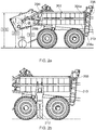
- FIGs 2a and 2b show a cutaway side view of a high density (HD) large square baler, in which a twine box 202 is shown.
- the twine box 202 can be covered by a shielding (not shown).
- the twine box 202 accommodates a plurality of spools of twine.
- the upper twine tray 208 is higher than the lower twine tray 210.
- the upper twine tray 208 is generally in line with the lower twine tray 210.
- each of the twine trays 208, 210 the spools of twine 204, 206 are spaced apart from each other in a longitudinal direction of the baler.
- the longitudinal direction of the baler is parallel to a direction of travel of the baler, and also parallel to the ground.
- twine box 202 Before going into a field with a large square baler, an operator will typically make sure that the twine box 202 is fully loaded with enough twine spools 204, 206. Often, the twine spools 204, 206 are manually threaded to neighbouring twine spools 204, 206 in the same twine tray 208, 210. In this way, a longer continuous piece of twine can be provided to the knotter system (not shown) of the baler from the twine box 202.
- balers especially HD large square balers, have twine boxes 202 that are relatively high above the ground.
- twine boxes 202 Various example dimensions of the twine trays 208, 210 are shown in Figure 2a :
- a twine spool may weigh about 12 - 13 kg, and perhaps up to 15 kg in the future.
- the upper twine tray 208 can be above head height of the operator 212
- the lower twine tray 210 can be at about head height of the operator 212. It is dangerous for the operator 212 to have to reach up (especially above his / her head) to load a twine spool 204, 206 into the twine box 202.
- twine cradles can be moved to a loading position, which is sufficiently low such that they can be comfortably and safely loaded with twine spools 204, 206 by an operator 212 at ground level. Then the twine cradles can be moved up to an operating position, as shown in Figures 2a and 2b .
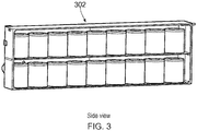
- FIG 3 shows a perspective view of the twine box 302, from the side of the baler.
- the baler can have two twine boxes 302, one on each side of the baler.
- FIGs 4a and 4b show a side view of an example embodiment of a twine box 402a, 402b.
- Figure 4a shows an empty twine box 402a; that is, one with no twine spools loaded in it.
- Figure 4b shows a loaded twine box 402b; that is, one with twine spools 404, 406 loaded in it.
- the twine box includes a frame 416 and three twine cradles 414, 414', 414", which are mounted to the frame 416.
- Each twine cradle defines part of an upper tray 408 of the twine box 402.
- the twine cradles 414 are for holding one or more spools of twine 404.
- each twine cradle 414 holds three spools of twine 404.
- the twine box 402 also includes a lower twine tray 410.
- the lower twine tray 410 does not include any twine cradles.
- the lower twine tray 410 may include twine cradles that are in addition to, or instead of, twine cradles 414 in the upper twine tray 408.
- a twine box may include more than two twine trays, in which case a middle twine tray may include twine cradles. This can be in addition to, or instead of, twine cradles 414 in the upper and / or lower twine trays 408,410.
- twine cradles 414 are movable between a loading position and an operational position, via an intermediate position, such that one or more spools of twine can be loaded into the twine cradles 414.
- FIGs 5a to 5c show schematic cross-sectional views, from the front of the baler, of the twine box of Figure 4 .
- the twine cradle 514 is in a loading position 518.
- the twine cradle 514 is in an intermediate position 520.
- the twine cradle 514 is in an operational position 522.
- an operator loads a twine spool 504 horizontally into the twine cradle 514 ( Figure 5a ), such that the twine spool has the desired vertical orientation when it is in the operational position 522 ( Figure 5c ).
- the twine cradle 514 is movable between the loading position 518 (as shown in Figure 5a ) and the operational position 522 (as shown in Figure 5c ), via the intermediate position 520 (as shown in Figure 5b ).
- a spool of twine 504 can be loaded into the twine cradle 514.
- twine can be removed from the spool of twine 504 that is within the twine cradle 514 in order to tie a bale.
- the twine cradle 514 is movable between the loading position 518 and the intermediate position 520 by a rotational movement 526 about a pivot 524.
- the pivot 524 defines a horizontal axis of rotation; that is, an axis that is parallel with the floor when the baler is in an upright orientation. The axis is also parallel with the longitudinal direction of the baler.
- the twine cradle 514 is movable between the intermediate position 520 and the operational position 522 by a translational movement 528.
- the translational movement 528 is rectilinear, and it can be in a direction that is generally parallel with the ground when the baler is in an upright orientation. This direction is also transverse to the longitudinal direction of the baler.
- the twine cradle 514 is movable between the loading position 518 and the intermediate position 520 without any significant translational movement; and the twine cradle 514 is movable between the intermediate position 520 and the operational position 522 without any significant rotational movement.
- the twine cradle 514 is movable between the intermediate position 520 and the operational position 522 with some rotational movement in addition to the translational movement 528. That is, a mechanism may be used that allows or causes the twine cradle 514 to rotate down or up during the sliding movement between the intermediate position 520 and the operational position 522.
- twine cradle can be lifted and the twine spools 504 can be slid into the twine box.
- the twine cradle 514 includes an end wall 530, a first side wall 532, and an optional second side wall 534.
- the first side wall 532 extends transversely from a first edge 536 of the end wall 530.
- the second side wall 534 extends transversely from a second edge 538 of the end wall 530.
- the first and second edges 536, 538 of the end wall 530 are opposing edges.
- the end wall 530 supports the weight of a spool of twine 504 in the twine cradle 514, when the twine cradle 514 is in the loading position 518. That is, the spool of twine 504 is located on top of the end wall 530 when the twine cradle 514 is in the loading position 518.
- the first wall 532 is configured to support the weight of the spool of twine 504 in the twine cradle 514, when the twine cradle 514 is in the intermediate position 520 and the operational position 522. That is, the spool of twine 504 is located on top of the first side wall 532 when the twine cradle 514 is in the intermediate position 520 and the operational position 522.
- the first side wall 532 has a distal end 540, which is distal from a connection to the end wall 530.
- the distal end 540 of the first side wall 532 is connected to the pivot 524 such that the twine cradle 514 is rotatable around the pivot 524 as the twine cradle 514 moves between the loading position 518 and the intermediate position 520.
- the pivot 524 is in a generally fixed position with respect to the frame 516 as the twine cradle 514 rotates between the loading position 518 and the intermediate position 520.
- the twine cradle 540 is rotatable by about 90 degrees between the loading position 518 and the intermediate position 520.
- the twine cradle 514 is movable downwards and outwards from the intermediate position 520 to the loading position 518 by the rotational movement 526 about the pivot 524.
- the twine cradle 514 is movable upwards from the loading position 518 to the intermediate position 520 by the rotational movement 526 about the pivot 524. In this way, when the twine cradle 514 is in the loading position 518 it is closer to the ground (base of the baler) than when it is in the intermediate position 520 and the operational position 522.
- twine cradle 514 When the twine cradle 514 is in the loading position 518 it can be at a height that is readily accessible to an operator in a safe and comfortable way. Also, in a lateral dimension of the baler, the twine cradle 514 is displaced outwards from the lower twine tray 510 when the twine cradle 514 is in the loading position 518.
- the distal end 540 of the first side wall 532 is in a generally fixed position with respect to the pivot 524 as the twine cradle 514 moves between the intermediate position 520 and the operational position 522.
- the pivot 524 is movable with respect to the frame 516 as the twine cradle 514 moves between the intermediate position 520 and the operational position 522.
- the pivot 524 can be connected to a heavy duty drawer slide that is mounted to the frame 516. In this way, the pivot 524 and the twine cradle 514 can move together relative to the frame 516.
- the pivot 524 / twine cradle 514 are movable closer to a centre plane 542 of the baler as the twine cradle 514 is movable from the intermediate position 520 to the operational position 522. That is, the twine cradle 514 is movable inwards from the intermediate position 520 to the operational position 522 by the translational movement.
- the pivot 524 / twine cradle 514 are movable further away from the centre plane 542 of the baler as the twine cradle 514 is movable from the operational position 522 to the intermediate position 520. That is, the twine cradle 514 is movable outwards from the operational position 522 to the intermediate position 520 by the translational movement.
- the twine cradle 514 also includes a second side wall 534.
- the second side wall 534 can be useful in ensuring that the twine spool 504 stays within the twine cradle 514 as it is moving between different positions.
- the second side wall 534 of Figure 5 includes an eyelet 544 for communicating twine from the spool of twine 504 in the twine cradle 514 to a knotter system (not shown) of the baler, when in use.
- the operator can thread the twine from a twine spool 504 through the eyelet 544 such that the end of the twine can be in a predetermined position that is spaced apart from the spool 504. This can advantageously assist a subsequent operation of providing the twine to the knotter system.
- the operator can beneficially thread the twine through the eyelet 544 when the twine cradle 514 is at an accessibly height in the loading position 518.
- the operator can also conveniently connect together free ends of neighbouring twine spools 504 when the twine cradle 514 is at an accessibly height in the loading position 518.
- the eyelet 544 is associated with a distal end 546 of the second side wall 534 of the twine cradle 514. This can be a convenient location for the knotter system in some balers. In other examples, the eyelet 544 can be provided at any other location on the twine cradle 514 such that it is accessible to an operator when the twine cradle is in the loading position 518, and is in an appropriate position for the knotter system when the twine cradle 514 is in the operational position 522.
- the twine eyelet 544 can be integrated into the twine cradle 514 as shown in the figure.
- the eyelet 544 is one example of twine-guidance-means that can be used to communicate twine from a spool of twine 504 in the twine cradle 514 to a knotter system of the baler, when in use.
- An operator can couple twine from the twine spool 504 to the twine-guidance-means when the twine cradle 514 is in the loading position.
- the twine-guidance-means need not necessarily have a completely enclosed shape; for example the twine-guidance-means can be provided as a notch or groove in any appropriate component or structure of the twine cradle 514.
- the mechanism for opening the shielding that covers the twine box can be designed such that when sliding out the twine cradle 514 from the operational position 522 to the intermediate position 520, it does not interfere with the shielding.
- the shielding may need to be relatively high above the ground when it is open, and in some examples may need to be in an almost horizontal position (parallel to the ground) when it is fully open.
- a twine tray can accommodate a plurality of spools of twine that are spaced apart in a longitudinal direction of the baler, and can provide twine to a knotter system of the baler. Furthermore, one or more of a plurality of twine cradles 514, in the operational position 522, can define at least part of an upper twine tray 508; and / or define at least part of a lower twine tray 510.
- each twine cradle carries 3 twine spools. In some applications this can be a good choice to cope with the total weight of the twine spools 504 when opening / closing the twine cradle 514. Also, as discussed above, the twines on the 3 spools in a common twine cradle 514 may be connected to each other, in order to service a single knotter. In this way, the connected twine spools can be referred to as a twine-spool-group.
- the twine cradle 514 is manually movable between the loading position 518 and the operational position 522, via the intermediate position 520.
- the twine cradle can include one or more actuators or biasing means for assisting with, or controlling, the movement of the twine cradle 514.
- actuators or biasing means for assisting with, or controlling, the movement of the twine cradle 514.
- gas struts, springs or something similar can be used.
- the walls of the twine cradle do not need to be solid walls; for example they can provided as meshes or any other tube-frame.
- FIG 6a shows a side view of another example embodiment of an empty twine box.
- Figure 6b shows schematically how twine spools can be loaded into the twine box of Figure 6a ; and in particular how twine spools can be associated into twine-spool-groups that are tied together to supply twine to a knotter in order to define a twine routing layout. That is, a twine-spool-group comprises a plurality of twine spools that are tied together such that they can provide a continued length of twine to a knotter from the plurality of twine spools.
- Figure 6a shows how a twine tray can comprise a plurality of twine cradles of different sizes; that is, twine cradles that accommodate different numbers of twine spools.
- Figures 6a and 6b together show how a single twine cradle can accommodate twine spools from a plurality of different twine-spool-groups, and can have a plurality of eyelets. Further details will be provided below.
- Figure 6a shows a twine box that has an upper twine tray 608 and a lower twine tray 610.
- the upper twine tray 608 includes three upper twine cradles: a first upper twine cradle 650 that can accommodate 3 twine spools; a second upper twine cradle 652 that can accommodate 2 twine spools; and a third upper twine cradle 654 that can accommodate 4 twine spools.
- the lower twine tray 610 includes two lower twine cradles: a first lower twine cradle 656 that can accommodate 5 twine spools; and a second lower twine cradle 658 that can accommodate 4 twine spools.
- each knotter of the baler has a top slacker arm and a bottom slacker arm. Due to the way that the knotter ties twine around the bales, the top slacker arm will use about twice as much twine as the bottom slacker arm.
- a twine-spool-group that includes 4 twine spools tied together is used to provide twine to the top slacker arm; and a twine-spool-group that includes 2 twine spools tied together is used to provide twine to the bottom slacker arm. Therefore, 6 twine spools in total are used for a single knotter.
- Figure 6b shows schematically how twine spools can be associated into twine-spool-groups for loading into the twine box of Figure 6a .
- the twine cradles of Figure 6a have been omitted from Figure 6b in order to more clearly illustrate the twine routing layout for the twine spools.
- Figure 6b shows 6 twine-spool-groups
- the plurality of twine cradles include a twine-guidance-means for each twine-spool-group.
- the twine-guidance-means are implemented as eyelets.
- a twine cradle can include one or a plurality of eyelets. In other layouts, a twine cradle may not include any eyelets at all.
- the twine box of Figure 6a includes the following eyelets:
- an operator can manually knot a twine spool to another twine spool in the same twine-spool-group when the twine cradle is in the loading position. Further still, the operator can thread the twine from the last twine spool in a twine-spool-group through the associated eyelet so that it is well positioned for connecting to the appropriate knotter system.
- the layouts of Figures 6a and 6b are non-limiting examples, and that different layouts can be used.
- the upper and / or lower twine trays 608, 610 can comprise: (i) a 4-spool twine cradle, a 3-spool twine cradle, and a 2-spool twine cradle; or (ii) a 4-spool twine cradle, and a 5-spool twine cradle.
- a twine tray 608, 610 may be sized to accommodate more or less than 9 twine spools.
- twine layout and twine cradle layout in order to control the twine cradle weight when it is fully loaded with twine spools.
- the design can take into account whether or not any mechanical assistance will be provided for moving a twine cradle (such as by a gas strut or spring as mentioned above), or if a twine cradle is intended to be fully manually operable.
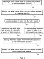
- Figure 7 schematically shows a method of loading a twine box of a baler.
- the method involves moving a twine cradle from an operational position to an intermediate position by a translational movement. For example, moving a twine cradle from the position of Figure 5c to the position of Figure 5b .
- the method involves moving the twine cradle from the intermediate position to a loading position by a rotational movement. For example, moving a twine cradle from the position of Figure 5b to the position of Figure 5a . In this way, the twine cradle is in a lower position than when it is in the operational position and therefore can be more conveniently and safely loaded by an operator.
- the method involves loading a spool of twine into the twine cradle.
- the method can also include step 710, which involves coupling twine from the spool of twine to a twine-guidance-means (such as the eyelet of Figures 5a to 5c ) that is associated with the twine cradle, while the twine cradle is in the loading position.
- the loading step 706 comprises loading a plurality of spools of twine into the twine cradle
- the method can include as step 708 connecting the twine from two or more of the plurality of spools of twine together while the twine cradle is in the loading position.
- the method then continues at step 712 by moving the twine cradle from the loading position to the intermediate position by a rotational movement. For example, by moving the twine cradle from the position of Figure 5a to the position of Figure 5b . Then the method involves moving the twine cradle from the intermediate position to the operational position by a translational movement. For example, by moving the twine cradle from the position of Figure 5b to the position of Figure 5c . In this way, the twine spools can be suitably located for connecting to a knotter system so that the baler is ready for use.
Landscapes
- Life Sciences & Earth Sciences (AREA)
- Environmental Sciences (AREA)
- Basic Packing Technique (AREA)
- Unwinding Of Filamentary Materials (AREA)
Abstract
Description
-
US 2012/0012012 A1 discloses a baler. The baler collects the harvested goods by means of collecting / pickup and conveying devices and supplies the collected harvested goods to a pressing device that forms the harvested goods into bales. In order to keep their shape permanently, the bales are tied by tying or binding material that is supplied to the bale from a storage container arranged on the baler and storing the tying material rolls. The storage container for the tying material rolls is pivotable from an operating position into a servicing position in order to allow access to machine parts that are covered in the operating position by the storage container. This movement can be performed preferably in a single / continuous curved path movement. -
US 2012/0012012 A1 also discloses that the storage container in another embodiment is pivoted to the side about a vertical axis that is arranged on the frame of the baler and is subsequently lowered in downward direction. -
EP 1121850 A1 discloses a rotobaler for agricultural product. In order to facilitate the transport of a material web roll from a storage location to the roll baler, this disclosure proposes that a loading device is designed as a mobile transport device for the web roll. A single loading device is thus usable both as an unwinding or storage station and serves at the same time for inserting the material web roll into the unwinding or stocking station and as a transport device from the storage location to the roll baler. - According to a first embodiment of the invention there is provided a baler comprising:
- a twine box, wherein the twine box comprises a frame and a twine cradle;
- wherein the twine cradle is for holding one or more spools of twine and is mounted to the frame, and wherein:
- the twine cradle is movable between a loading position and an operational position, via an intermediate position;
- in the loading position, a spool of twine can be loaded into the twine cradle;
- in the operational position, twine can be removed from a spool of twine within the twine cradle in order to tie a bale;
- the twine cradle is movable between the loading position and the intermediate position by a rotational movement about a pivot that defines a horizontal axis of rotation; and
- the twine cradle is movable between the intermediate position and the operational position by a translational movement, wherein the pivot is configured to be movable with respect to the frame as the twine cradle moves between the intermediate position and the operational position.
- Such a baler can provide a convenient and safe mechanism for an operator to load spools of twine into the twine box. Also, using a pivot that defines a horizontal axis of rotation can result in only a modest amount of free space being required to the side of the baler when lowering the twine cradle, can reduce the requirements of any hinges or other mechanisms that are used to provide the pivot, and may not require a stop or a lock to control the range of motion of the twine cradle.
- The twine cradle may be movable between the loading position and the intermediate position without any significant translational movement. The twine cradle may be movable between the intermediate position and the operational position without any significant rotational movement.
- The twine cradle may be configured to accommodate a plurality of spools of twine. The twine cradle may be configured to accommodate 2, 3 4, 5, or 6 spools of twine.
- The twine cradle may include an end wall and a first side wall. The first side wall may extend transversely from a first edge of the end wall. The end wall may be configured to support the weight of a spool of twine in the twine cradle, when the twine cradle is in the loading position. The first side wall may be configured to support the weight of a spool of twine in the twine cradle, when the twine cradle is in the intermediate position and the operational position.
- A distal end of the first side wall (that is distal from the end wall) may be connected to the pivot such that the twine cradle is rotatable around the pivot as the twine cradle moves between the loading position and the intermediate position. The pivot may be configured to be in a generally fixed position with respect to the frame as the twine cradle moves between the loading position and the intermediate position. The twine cradle may be movable upwards from the loading position to the intermediate position by the rotational movement about the pivot. The twine cradle may be movable downwards from the intermediate position to the loading position by the rotational movement about the pivot. The twine cradle may be movable by about 90 degrees between the loading position and the intermediate position.
- The distal end of the first side wall may be configured to be in a generally fixed position with respect to the pivot as the twine cradle moves between the intermediate position and the operational position.
- The pivot may be configured to be movable with respect to the frame as the twine cradle moves between the intermediate position and the operational position. The pivot / twine cradle may be movable closer to a centre plane of the baler as the twine cradle is movable from the intermediate position to the operational position. The twine cradle may be movable inwards from the intermediate position to the operational position by the translational movement. The twine cradle may be movable outwards from the operational position to the intermediate position by the translational movement.
- When the twine cradle is in the loading position it may be closer to the ground / base of the baler than when it is in the intermediate position and the operational position.
- The twine cradle may comprise twine-guidance-means for communicating twine from a spool of twine in the twine cradle to a knotter system of the baler, when in use.
- The twine cradle may comprise a second side wall that extends transversely from a second edge of the end wall. The first and second edges of the end wall may be opposing edges. The twine-guidance-means may comprise an eyelet. The eyelet may be associated with a distal end of the second side wall of the twine cradle.
- The baler may comprise a twine tray, which may include an upper twine tray and a lower twine tray. The twine tray(s) may be configured to: accommodate a plurality of spools of twine, which may be spaced apart in a longitudinal direction of the baler; and provide twine to a knotter system of the baler. One or more twine cradles, in the operational position, may define at least part of one or more of the twine trays. A plurality of twine cradles may be spaced apart in a longitudinal direction of the baler.
- A twine tray may comprise a plurality of twine cradles of different sizes; that is, twine cradles that accommodate different numbers of twine spools. A single twine cradle can accommodate twine spools from a plurality of different twine-spool-groups, and can have a plurality of twine-guidance-means.
- The twine cradle may be manually movable between the loading position and the operational position, via the intermediate position.
- There may be provided a method of loading a twine box of a baler, the method comprising:
- moving a twine cradle from an operational position to an intermediate position by a translational movement;
- moving the twine cradle from the intermediate position to a loading position by a rotational movement;
- loading a spool of twine into the twine cradle;
- moving the twine cradle from the loading position to the intermediate position by a rotational movement; and
- moving the twine cradle from the intermediate position to the operational position by a translational movement.
- There is also provided a method of loading a twine box of a baler, the method comprising:
- moving a twine cradle from an operational position to an intermediate position by a translational movement, such that a pivot moves with respect to the baler;
- moving the twine cradle from the intermediate position to a loading position by a rotational movement about the pivot that defines a horizontal axis of rotation;
- loading a spool of twine into the twine cradle;
- moving the twine cradle from the loading position to the intermediate position by a rotational movement about the pivot; and
- moving the twine cradle from the intermediate position to the operational position by a translational movement such that the pivot moves with respect to the baler.
- The loading step of any method disclosed herein may comprise loading a plurality of spools of twine into the twine cradle, and optionally connecting the twine from two or more of the plurality of spools of twine together while the twine cradle is in the loading position.
- Any of the methods disclosed herein may further comprise:
coupling twine from the spool of twine to a twine-guidance-means that is associated with the twine cradle while the twine cradle is in the loading position. - There is also provided a baler comprising:
- a twine box, wherein the twine box comprises a frame and a twine cradle;
- wherein the twine cradle is for holding one or more spools of twine and is mounted to the frame, and wherein:
- the twine cradle is movable between a loading position and an operational position, via an intermediate position;
- in the loading position, a spool of twine can be loaded into the twine cradle;
- in the operational position, twine can be removed from a spool of twine within the twine cradle in order to tie a bale;
- the twine cradle is movable between the loading position and the intermediate position by a rotational movement about a pivot that defines a horizontal axis of rotation; and
- the twine cradle is movable between the intermediate position and the operational position by a translational movement.
- Such a baler can include any of the features of the other balers disclosed herein.
- There now follows a description of preferred embodiments of the invention, by way of non-limiting example, with reference being made to the accompanying drawings in which:
-
Figure 1 shows an agricultural harvester in the form of a large square baler; -
Figures 2a and 2b show a cutaway side view of a high density (HD) large square baler, in which a twine box is shown; -
Figure 3 shows a perspective view of the twine box, from the side of the baler; -
Figures 4a and 4b show a side view of an example embodiment of a twine box; -
Figures 5a to 5c show schematic cross-sectional views, from the front of the baler, of the twine box ofFigure 4 ; -
Figure 6a shows a side view of another example embodiment of an empty twine box; -
Figure 6b shows schematically how twine spools can be loaded into the twine box ofFigure 6a ; and -
Figure 7 schematically shows a method of loading a twine box of a baler. -
Figure 1 shows an agricultural harvester in the form of a largesquare baler 10.Figure 1 is a perspective cutaway view showing the internal workings of the largesquare baler 10. The largesquare baler 10 operates on a two stage feeding system. Crop material is lifted from windrows into the largesquare baler 10 using a pickup unit 12. The pickup unit 12 includes arotating pickup roll 14 withtines 16 which move the crop rearward toward apacker unit 18. An optional pair of stub augers (one of which is shown, but not numbered) are positioned above therotating pickup roll 14 to move the crop material laterally inward. Thepacker unit 18 includespacker tines 20 which push the crop into apre-compression chamber 22 to form a wad of crop material. Thepacker tines 20 intertwine the crop together and pack the crop withinpre-compression chamber 22. Thepre-compression chamber 22 and thepacker tines 20 function as the first stage for crop compression. - Once the pressure in the
pre-compression chamber 22 reaches a predetermined sensed value, astuffer unit 24 moves the wad of crop from thepre-compression chamber 22 into aninlet end 40 of abale chamber 26. Thestuffer unit 24 includesstuffer forks 28 which thrust the wad of crop directly in front of aplunger 30, which reciprocates within thebale chamber 26 and compresses the wad of crop into a flake. Thestuffer forks 28 return to their original stationary state after the wad of material has been moved into thebale chamber 26. Theplunger 30 compresses the wads of crop into flakes to form a bale and, at the same time, gradually advances the bale toward anoutlet end 32 of thebale chamber 26. Thebale chamber 26 andplunger 30 function as the second stage for crop compression. When enough flakes have been added and the bale reaches a full (or other predetermined) size, knotters 34 are actuated which wrap and tie twine around the bale while it is still in thebale chamber 26.Needles 36 bring the lower twine up to theknotters 34 and the tying process then takes place. The twine is cut and the formed bale is ejected from adischarge chute 38 as a new bale is formed. - It will be appreciated that the examples described below can be used with different types of baler, including a packer type large square baler and a rotor type large square baler, that is either standard or high density.
-
Figures 2a and 2b show a cutaway side view of a high density (HD) large square baler, in which atwine box 202 is shown. When the baler is in use, thetwine box 202 can be covered by a shielding (not shown). - The
twine box 202 accommodates a plurality of spools of twine. In this example there are 18 spools of twine: 9 spools oftwine 204a-i are provided in anupper twine tray 208; and 9 spools oftwine 206a-i are provided in alower twine tray 210. Theupper twine tray 208 is higher than thelower twine tray 210. In a lateral dimension of the baler (that is transverse to the direction of travel of the baler, and generally parallel with the ground), theupper twine tray 208 is generally in line with thelower twine tray 210. In each of thetwine trays - Before going into a field with a large square baler, an operator will typically make sure that the
twine box 202 is fully loaded with enough twine spools 204, 206. Often, the twine spools 204, 206 are manually threaded to neighbouring twine spools 204, 206 in thesame twine tray twine box 202. - Some balers, especially HD large square balers, have
twine boxes 202 that are relatively high above the ground. Various example dimensions of thetwine trays Figure 2a : - The lower edge of the
lower twine tray 210, which corresponds to a bottom surface of a spool of twine in thelower twine tray 210, is approximately 1,612mm above the ground; - A top surface of a spool of twine in the
lower twine tray 210 is approximately 1,966mm above the ground; - The lower edge of the
upper twine tray 208, which corresponds to a bottom surface of a spool of twine in theupper twine tray 208, is approximately 2,071 mm above the ground; and - A top surface of a spool of twine in the
upper twine tray 208 is approximately 2,425mm above the ground. - It is important that an operator can load the twine spools 204, 206 into the
twine box 202 in a comfortable way. A twine spool may weigh about 12 - 13 kg, and perhaps up to 15 kg in the future. As shown inFigure 2b , theupper twine tray 208 can be above head height of theoperator 212, and thelower twine tray 210 can be at about head height of theoperator 212. It is dangerous for theoperator 212 to have to reach up (especially above his / her head) to load a twine spool 204, 206 into thetwine box 202. - In order to increase the comfort and safety with which the
operator 212 can load twine spools into thetwine box 202, the relative positioning between the twine spools 204, 206 and theoperator 212 can be changed. For example, theoperator 212 can climb up a ladder or onto a step to increase their height above the ground. However, this can still be dangerous for theoperator 212. Described below are examples of how twine cradles can be moved to a loading position, which is sufficiently low such that they can be comfortably and safely loaded with twine spools 204, 206 by anoperator 212 at ground level. Then the twine cradles can be moved up to an operating position, as shown inFigures 2a and 2b . -
Figure 3 shows a perspective view of thetwine box 302, from the side of the baler. In some applications, the baler can have twotwine boxes 302, one on each side of the baler. -
Figures 4a and 4b show a side view of an example embodiment of atwine box Figure 4a shows anempty twine box 402a; that is, one with no twine spools loaded in it.Figure 4b shows a loadedtwine box 402b; that is, one with twine spools 404, 406 loaded in it. In this example, the twine box includes aframe 416 and three twine cradles 414, 414', 414", which are mounted to theframe 416. Each twine cradle defines part of anupper tray 408 of the twine box 402. As shown inFigure 4b , the twine cradles 414 are for holding one or more spools of twine 404. In this example, eachtwine cradle 414 holds three spools of twine 404. - The twine box 402 also includes a
lower twine tray 410. In this example, thelower twine tray 410 does not include any twine cradles. However, in other examples thelower twine tray 410 may include twine cradles that are in addition to, or instead of, twine cradles 414 in theupper twine tray 408. In further examples still, a twine box may include more than two twine trays, in which case a middle twine tray may include twine cradles. This can be in addition to, or instead of, twine cradles 414 in the upper and / or lower twine trays 408,410. - As will be discussed below, the twine cradles 414 are movable between a loading position and an operational position, via an intermediate position, such that one or more spools of twine can be loaded into the twine cradles 414.
-
Figures 5a to 5c show schematic cross-sectional views, from the front of the baler, of the twine box ofFigure 4 . InFigure 5a thetwine cradle 514 is in aloading position 518. InFigure 5b thetwine cradle 514 is in an intermediate position 520. InFigure 5c thetwine cradle 514 is in anoperational position 522. As shown inFigures 5a and 5c , an operator loads atwine spool 504 horizontally into the twine cradle 514 (Figure 5a ), such that the twine spool has the desired vertical orientation when it is in the operational position 522 (Figure 5c ). - The
twine cradle 514 is movable between the loading position 518 (as shown inFigure 5a ) and the operational position 522 (as shown inFigure 5c ), via the intermediate position 520 (as shown inFigure 5b ). In theloading position 518, a spool oftwine 504 can be loaded into thetwine cradle 514. In theoperational position 522, twine can be removed from the spool oftwine 504 that is within thetwine cradle 514 in order to tie a bale. - The
twine cradle 514 is movable between theloading position 518 and the intermediate position 520 by arotational movement 526 about apivot 524. Thepivot 524 defines a horizontal axis of rotation; that is, an axis that is parallel with the floor when the baler is in an upright orientation. The axis is also parallel with the longitudinal direction of the baler. - The
twine cradle 514 is movable between the intermediate position 520 and theoperational position 522 by atranslational movement 528. In this example thetranslational movement 528 is rectilinear, and it can be in a direction that is generally parallel with the ground when the baler is in an upright orientation. This direction is also transverse to the longitudinal direction of the baler. As shown inFigure 5b , thetwine cradle 514 is movable between theloading position 518 and the intermediate position 520 without any significant translational movement; and thetwine cradle 514 is movable between the intermediate position 520 and theoperational position 522 without any significant rotational movement. In other examples, thetwine cradle 514 is movable between the intermediate position 520 and theoperational position 522 with some rotational movement in addition to thetranslational movement 528. That is, a mechanism may be used that allows or causes thetwine cradle 514 to rotate down or up during the sliding movement between the intermediate position 520 and theoperational position 522. - In this way, the twine cradle can be lifted and the twine spools 504 can be slid into the twine box.
- Advantages of rotating a twine cradle about a horizontal axis (as shown in
Figures 5a and 5b ) include: - Only a modest amount of free space is required to the side of the baler when lowering the
twine cradle 514. For example, if the baler is parked in a building, then an operator only requires enough room on the side of the baler to open the twine box panel / shielding. Pulling thetwine cradle 514 to the loading / service position ofFigure 5a may not require any extra space because it can only occupy the height of a spool and potentially some associated framework (an approximate maximum of 40 cm in some applications). Therefore, using apivot 524 for rotation about a horizontal axis can be particularly favourable when the baler is in a workshop; whereas pivoting a whole twine box around a vertical axis would require much more space and clearance around the baler. - A twine cradle can more readily be implemented as part of a single twine tray, and does not necessarily need to accommodate twine spools that fill the entire height of the twine box (the upper and lower twine trays as they are described herein). This can result in the twine cradle being relatively short, a little more than the height of a single twine spool, such that a relatively small amount of clearance on the side of the baler is required to load twine spools into the twine box.
- Hinging a
twine cradle 514 horizontally may require hinges that are not as strong and robust as would be required for rotating a twine cradle about a vertical axis. Also, less deformation of the hinges / rotational mechanism and thetwine cradle 514 can be expected when rotating thetwine cradle 514 about a horizontal axis. - It may not be necessary to have a stop or a lock when hinging the
twine 514 cradle horizontally; instead gravity can automatically control the range of motion of thetwine cradle 514. In contrast, if a vertically hinged twine cradle were used, then a stop or lock may be required to prevent a twine cradle from over-rotating. - It can be convenient to split a twine tray into multiple twine cradles 514. In this way, the number of spools in a twine tray, and therefore also the associated weight of a fully loaded
twine cradle 514 can be controlled such that the twine cradles can be moved between different positions by hand. In contrast, if a vertically hinged twine cradle were used, then it may be more difficult or impossible for a plurality of twine cradles to be used for a single twine tray. For instance, the mechanisms that would be required may be complicated in order to ensure that movement of one twine cradle does not foul another of the twine cradles. - In the example of
Figures 5a-c , thetwine cradle 514 includes anend wall 530, afirst side wall 532, and an optionalsecond side wall 534. Thefirst side wall 532 extends transversely from afirst edge 536 of theend wall 530. Thesecond side wall 534 extends transversely from asecond edge 538 of theend wall 530. The first andsecond edges end wall 530 are opposing edges. - As shown in
Figure 5a , theend wall 530 supports the weight of a spool oftwine 504 in thetwine cradle 514, when thetwine cradle 514 is in theloading position 518. That is, the spool oftwine 504 is located on top of theend wall 530 when thetwine cradle 514 is in theloading position 518. As shown inFigures 5b and 5c , thefirst wall 532 is configured to support the weight of the spool oftwine 504 in thetwine cradle 514, when thetwine cradle 514 is in the intermediate position 520 and theoperational position 522. That is, the spool oftwine 504 is located on top of thefirst side wall 532 when thetwine cradle 514 is in the intermediate position 520 and theoperational position 522. - The
first side wall 532 has adistal end 540, which is distal from a connection to theend wall 530. Thedistal end 540 of thefirst side wall 532 is connected to thepivot 524 such that thetwine cradle 514 is rotatable around thepivot 524 as thetwine cradle 514 moves between theloading position 518 and the intermediate position 520. Thepivot 524 is in a generally fixed position with respect to theframe 516 as thetwine cradle 514 rotates between theloading position 518 and the intermediate position 520. - As shown in
Figures 5a and 5b , in this example thetwine cradle 540 is rotatable by about 90 degrees between theloading position 518 and the intermediate position 520. In this way, thetwine cradle 514 is movable downwards and outwards from the intermediate position 520 to theloading position 518 by therotational movement 526 about thepivot 524. Similarly, thetwine cradle 514 is movable upwards from theloading position 518 to the intermediate position 520 by therotational movement 526 about thepivot 524. In this way, when thetwine cradle 514 is in theloading position 518 it is closer to the ground (base of the baler) than when it is in the intermediate position 520 and theoperational position 522. When thetwine cradle 514 is in theloading position 518 it can be at a height that is readily accessible to an operator in a safe and comfortable way. Also, in a lateral dimension of the baler, thetwine cradle 514 is displaced outwards from thelower twine tray 510 when thetwine cradle 514 is in theloading position 518. - The
distal end 540 of thefirst side wall 532 is in a generally fixed position with respect to thepivot 524 as thetwine cradle 514 moves between the intermediate position 520 and theoperational position 522. Thepivot 524 is movable with respect to theframe 516 as thetwine cradle 514 moves between the intermediate position 520 and theoperational position 522. For example, thepivot 524 can be connected to a heavy duty drawer slide that is mounted to theframe 516. In this way, thepivot 524 and thetwine cradle 514 can move together relative to theframe 516. Thepivot 524 /twine cradle 514 are movable closer to acentre plane 542 of the baler as thetwine cradle 514 is movable from the intermediate position 520 to theoperational position 522. That is, thetwine cradle 514 is movable inwards from the intermediate position 520 to theoperational position 522 by the translational movement. Similarly, thepivot 524 /twine cradle 514 are movable further away from thecentre plane 542 of the baler as thetwine cradle 514 is movable from theoperational position 522 to the intermediate position 520. That is, thetwine cradle 514 is movable outwards from theoperational position 522 to the intermediate position 520 by the translational movement. - As indicated above, in this example the
twine cradle 514 also includes asecond side wall 534. Thesecond side wall 534 can be useful in ensuring that thetwine spool 504 stays within thetwine cradle 514 as it is moving between different positions. Also, thesecond side wall 534 ofFigure 5 includes aneyelet 544 for communicating twine from the spool oftwine 504 in thetwine cradle 514 to a knotter system (not shown) of the baler, when in use. For example, when thetwine cradle 514 is in theloading position 518, the operator can thread the twine from atwine spool 504 through theeyelet 544 such that the end of the twine can be in a predetermined position that is spaced apart from thespool 504. This can advantageously assist a subsequent operation of providing the twine to the knotter system. - Furthermore, the operator can beneficially thread the twine through the
eyelet 544 when thetwine cradle 514 is at an accessibly height in theloading position 518. The operator can also conveniently connect together free ends of neighbouring twine spools 504 when thetwine cradle 514 is at an accessibly height in theloading position 518. - In this example, the
eyelet 544 is associated with adistal end 546 of thesecond side wall 534 of thetwine cradle 514. This can be a convenient location for the knotter system in some balers. In other examples, theeyelet 544 can be provided at any other location on thetwine cradle 514 such that it is accessible to an operator when the twine cradle is in theloading position 518, and is in an appropriate position for the knotter system when thetwine cradle 514 is in theoperational position 522. Thetwine eyelet 544 can be integrated into thetwine cradle 514 as shown in the figure. - The
eyelet 544 is one example of twine-guidance-means that can be used to communicate twine from a spool oftwine 504 in thetwine cradle 514 to a knotter system of the baler, when in use. An operator can couple twine from thetwine spool 504 to the twine-guidance-means when thetwine cradle 514 is in the loading position. In some examples, the twine-guidance-means need not necessarily have a completely enclosed shape; for example the twine-guidance-means can be provided as a notch or groove in any appropriate component or structure of thetwine cradle 514. - The mechanism for opening the shielding that covers the twine box can be designed such that when sliding out the
twine cradle 514 from theoperational position 522 to the intermediate position 520, it does not interfere with the shielding. The shielding may need to be relatively high above the ground when it is open, and in some examples may need to be in an almost horizontal position (parallel to the ground) when it is fully open. - It will be appreciated from the description of
Figures 4a and 4b that a twine tray can accommodate a plurality of spools of twine that are spaced apart in a longitudinal direction of the baler, and can provide twine to a knotter system of the baler. Furthermore, one or more of a plurality of twine cradles 514, in theoperational position 522, can define at least part of anupper twine tray 508; and / or define at least part of alower twine tray 510. - In the example of
Figures 4a and 4b , each twine cradle carries 3 twine spools. In some applications this can be a good choice to cope with the total weight of the twine spools 504 when opening / closing thetwine cradle 514. Also, as discussed above, the twines on the 3 spools in acommon twine cradle 514 may be connected to each other, in order to service a single knotter. In this way, the connected twine spools can be referred to as a twine-spool-group. - In this example, the
twine cradle 514 is manually movable between theloading position 518 and theoperational position 522, via the intermediate position 520. On other examples, the twine cradle can include one or more actuators or biasing means for assisting with, or controlling, the movement of thetwine cradle 514. For example, gas struts, springs or something similar can be used. - As shown in
Figures 4a and 4b , the walls of the twine cradle do not need to be solid walls; for example they can provided as meshes or any other tube-frame. -
Figure 6a shows a side view of another example embodiment of an empty twine box.Figure 6b shows schematically how twine spools can be loaded into the twine box ofFigure 6a ; and in particular how twine spools can be associated into twine-spool-groups that are tied together to supply twine to a knotter in order to define a twine routing layout. That is, a twine-spool-group comprises a plurality of twine spools that are tied together such that they can provide a continued length of twine to a knotter from the plurality of twine spools.Figure 6a shows how a twine tray can comprise a plurality of twine cradles of different sizes; that is, twine cradles that accommodate different numbers of twine spools.Figures 6a and 6b together show how a single twine cradle can accommodate twine spools from a plurality of different twine-spool-groups, and can have a plurality of eyelets. Further details will be provided below. -
Figure 6a shows a twine box that has anupper twine tray 608 and alower twine tray 610. Theupper twine tray 608 includes three upper twine cradles: a firstupper twine cradle 650 that can accommodate 3 twine spools; a secondupper twine cradle 652 that can accommodate 2 twine spools; and a thirdupper twine cradle 654 that can accommodate 4 twine spools. Thelower twine tray 610 includes two lower twine cradles: a firstlower twine cradle 656 that can accommodate 5 twine spools; and a secondlower twine cradle 658 that can accommodate 4 twine spools. - For this application, each knotter of the baler has a top slacker arm and a bottom slacker arm. Due to the way that the knotter ties twine around the bales, the top slacker arm will use about twice as much twine as the bottom slacker arm. In this example, a twine-spool-group that includes 4 twine spools tied together is used to provide twine to the top slacker arm; and a twine-spool-group that includes 2 twine spools tied together is used to provide twine to the bottom slacker arm. Therefore, 6 twine spools in total are used for a single knotter. The baler associated with the twine box of
Figure 6a has 6 knotters, and therefore the baler requires 36 twine spools. The twine box ofFigure 6a can accommodate 18 twine spools. The baler can also have a second twine box, on the opposite side of the baler, for accommodating another 8 twine spools. The second twine box may the same as the twine box ofFigure 6a . -
Figure 6b shows schematically how twine spools can be associated into twine-spool-groups for loading into the twine box ofFigure 6a . The twine cradles ofFigure 6a have been omitted fromFigure 6b in order to more clearly illustrate the twine routing layout for the twine spools. -
Figure 6b shows 6 twine-spool-groups: - a first-twine-spool-
group 668, which includes 4twine spools 668a-d that are tied together (as indicated by the curved arrows between the twine spools 668a-d) for providing twine to a top slacker arm of a first knotter; - a second-twine-spool-
group 660, which includes 2twine spools 660a-b that are tied together for providing twine to a bottom slacker arm of the first knotter; - a third-twine-spool-
group 666, which includes 4twine spools 666a-d that are tied together for providing twine to a top slacker arm of a second knotter; - a fourth-twine-spool-
group 662, which includes 2twine spools 662a-b that are tied together for providing twine to a bottom slacker arm of the second knotter; - a fifth-twine-spool-
group 670, which includes 4twine spools 670a-d that are tied together for providing twine to a top slacker arm of a third knotter; and - a sixth-twine-spool-
group 664, which includes 2twine spools 664a-b that are tied together for providing twine to a bottom slacker arm of the third knotter. - As can be seen from
Figures 6a and 6b : - the first
upper twine cradle 650 accommodates: (i) the fourth-twine-spool-group 662; and also (ii) one of thetwine spools 660a from the second-twine-spool-group 660. In this way, a twine cradle can accommodate a subset of twine spools from a twine-spool-group, optionally along with twine spools from a different twine-spool-group; - the second
upper twine cradle 652 accommodates the sixth-twine-spool-group 664; - the third
upper twine cradle 654 accommodates the third-twine-spool-group 666; - the first
lower twine cradle 656 accommodates: (i) the first-twine-spool-group 668; and also (ii) one of the twine spools 660b from the second-twine-spool-group 660; and - the second
lower twine cradle 658 accommodates the fifth-twine-spool-group 670. - The plurality of twine cradles, between them, include a twine-guidance-means for each twine-spool-group. In this example, the twine-guidance-means are implemented as eyelets. As will be discussed below, depending upon the twine layout, a twine cradle can include one or a plurality of eyelets. In other layouts, a twine cradle may not include any eyelets at all.
- The twine box of
Figure 6a includes the following eyelets: - a first-
eyelet 678, for the first-twine-spool-group 668, which is provided on the firstlower twine cradle 656. In this example the first-eyelet 678 is spaced apart (in a longitudinal dimension of the baler / twine box) from an end of thecradle 656 because the cradle also includes atwine spool 660b from a different twine-spool-group; - a second-
eyelet 672, for the second-twine-spool-group 660, which is provided on the firstupper twine cradle 650; - a third-
eyelet 676, for the third-twine-spool-group 666, which is provided on the thirdupper twine cradle 654; - a fourth-
eyelet 673, for the fourth-twine-spool-group 662, which is provided on the firstupper twine cradle 650. In this example, because the firstupper twine cradle 650 accommodates thelast twine spool groups upper twine cradle 650 includes 2eyelets - a fifth-
eyelet 680, for the fifth-twine-spool-group 670, which is provided on the secondlower twine cradle 658; and - a sixth-
eyelet 674, for the sixth-twine-spool-group 664, which is provided on the secondupper twine cradle 652. - Advantageously, an operator can manually knot a twine spool to another twine spool in the same twine-spool-group when the twine cradle is in the loading position. Further still, the operator can thread the twine from the last twine spool in a twine-spool-group through the associated eyelet so that it is well positioned for connecting to the appropriate knotter system.
- It will be appreciated that the layouts of
Figures 6a and 6b are non-limiting examples, and that different layouts can be used. For instance, the upper and / orlower twine trays twine tray - In some applications it can be beneficial to design the twine layout and twine cradle layout in order to control the twine cradle weight when it is fully loaded with twine spools. The design can take into account whether or not any mechanical assistance will be provided for moving a twine cradle (such as by a gas strut or spring as mentioned above), or if a twine cradle is intended to be fully manually operable.
-
Figure 7 schematically shows a method of loading a twine box of a baler. - At
step 702, the method involves moving a twine cradle from an operational position to an intermediate position by a translational movement. For example, moving a twine cradle from the position ofFigure 5c to the position ofFigure 5b . - At
step 704, the method involves moving the twine cradle from the intermediate position to a loading position by a rotational movement. For example, moving a twine cradle from the position ofFigure 5b to the position ofFigure 5a . In this way, the twine cradle is in a lower position than when it is in the operational position and therefore can be more conveniently and safely loaded by an operator. - At
step 706, the method involves loading a spool of twine into the twine cradle. Optionally, the method can also includestep 710, which involves coupling twine from the spool of twine to a twine-guidance-means (such as the eyelet ofFigures 5a to 5c ) that is associated with the twine cradle, while the twine cradle is in the loading position. Also optionally, if theloading step 706 comprises loading a plurality of spools of twine into the twine cradle, then the method can include asstep 708 connecting the twine from two or more of the plurality of spools of twine together while the twine cradle is in the loading position. - The method then continues at
step 712 by moving the twine cradle from the loading position to the intermediate position by a rotational movement. For example, by moving the twine cradle from the position ofFigure 5a to the position ofFigure 5b . Then the method involves moving the twine cradle from the intermediate position to the operational position by a translational movement. For example, by moving the twine cradle from the position ofFigure 5b to the position ofFigure 5c . In this way, the twine spools can be suitably located for connecting to a knotter system so that the baler is ready for use. - Throughout the present specification, the descriptors relating to relative orientation and position, such as "horizontal", "vertical", "top", "bottom" and "side", are used in the sense of the orientation of the baler as presented in the drawings. However, such descriptors are not intended to be in any way limiting to an intended use of the described or claimed invention.
Claims (15)
- A baler comprising:a twine box (402), wherein the twine box comprises a frame (516) and a twine cradle (514);wherein the twine cradle (514) is for holding one or more spools of twine (504) and is mounted to the frame (516), and wherein:the twine cradle (514) is movable between a loading position (518) and an operational position (522), via an intermediate position (520);in the loading position (518), a spool of twine (504) can be loaded into the twine cradle (514);in the operational position (522), twine can be removed from a spool of twine (504) within the twine cradle (514) in order to tie a bale;the twine cradle (514) is movable between the loading position (518) and the intermediate position (520) by a rotational movement (526) about a pivot (524) that defines a horizontal axis of rotation; andthe twine cradle (514) is movable between the intermediate position (520) and the operational position (522) by a translational movement (528), wherein the pivot (524) is configured to be movable with respect to the frame (516) as the twine cradle moves between the intermediate position and the operational position.
- The baler of claim 1, wherein the twine cradle (514) is configured to accommodate a plurality of spools of twine (504).
- The baler of claim 1, wherein:the twine cradle (514) is movable between the loading position (518) and the intermediate position (520) without any significant translational movement; andthe twine cradle (514) is movable between the intermediate position (520) and the operational position (522) without any significant rotational movement.
- The baler of claim 1, wherein the twine cradle (514) includes an end wall (530) and a first side wall (532), wherein:the first side wall (532) extends transversely from a first edge (536) of the end wall (530);the end wall (530) is configured to support the weight of a spool of twine (504) in the twine cradle (514), when the twine cradle (514) is in the loading position (518); andthe first side wall (532) is configured to support the weight of a spool of twine (504) in the twine cradle (514), when the twine cradle (514) is in the intermediate position (520) and the operational position (522).
- The baler of claim 3, wherein a distal end (540) of the first side wall (532) is connected to the pivot (524) such that the twine cradle (514) is rotatable around the pivot (524) as the twine cradle (514) moves between the loading position (518) and the intermediate position (520).
- The baler of claim 4, wherein:
the distal end of the first side wall (532) is configured to be in a generally fixed position with respect to the pivot (524) as the twine cradle (514) moves between the intermediate position (520) and the operational position (522). - The baler of claim 1, wherein the pivot (524) is configured to be in a generally fixed position with respect to the frame as the twine cradle (514) moves between the loading position (518) and the intermediate position (520).
- The baler of claim 1, wherein the twine cradle (514) is movable downwards from the intermediate position (520) to the loading position (518) by the rotational movement (526) about the pivot (524).
- The baler of claim 1, wherein the twine cradle (514) is movable inwards from the intermediate position (520) to the operational position (522) by the translational movement (528).
- The baler of claim 1, wherein the twine cradle (514) comprises twine-guidance-means (544) for communicating twine from a spool of twine (504) in the twine cradle (514) to a knotter system of the baler, when in use.
- The baler of claim 10, wherein:the twine cradle (514) comprises a second side wall (534) that extends transversely from a second edge (538) of the end wall (530), wherein the first and second edges of the end wall (530) are opposing edges; andthe twine-guidance-means (544) is associated with a distal end (546) of the second side wall (534) of the twine cradle (514).
- The baler of claim 1, wherein:
the baler comprises a twine tray, wherein the twine tray is configured to:accommodate a plurality of spools of twine that are spaced apart in a longitudinal direction of the baler; andprovide twine to a knotter system of the baler; andthe twine cradle (514), in the operational position (522), defines at least part of the twine tray. - The baler of claim 1, further comprising a plurality of twine cradles (514), and wherein:the baler comprises an upper twine tray (508) and a lower twine tray (510);one or more of the plurality of twine cradles (514), in the operational position (522), defines at least part of the upper twine tray (508); andone or more of the plurality of twine cradles (514), in the operational position (522), defines at least part of the lower twine tray (510).
- The baler of claim 1, wherein the twine cradles (514) is manually movable between the loading position (518) and the operational position (522), via the intermediate position (520).
- A method of loading a twine box (402) of a baler, the method comprising:moving a twine cradle (514) from an operational position (522) to an intermediate position (520) by a translational movement (528), such that a pivot (524) moves with respect to the baler;moving the twine cradle (514) from the intermediate position (520) to a loading position (518) by a rotational movement (526) about the pivot (524) that defines a horizontal axis of rotation;loading a spool of twine (504) into the twine cradle (514);moving the twine cradle (514) from the loading position (518) to the intermediate position (520) by a rotational movement (526) about the pivot (524); andmoving the twine cradle (514) from the intermediate position (520) to the operational position (522) by a translational movement (528) such that the pivot (524) moves with respect to the baler.
Applications Claiming Priority (1)
| Application Number | Priority Date | Filing Date | Title |
|---|---|---|---|
| BE20185474A BE1026444B1 (en) | 2018-07-05 | 2018-07-05 | BALEN PRESS |
Publications (2)
| Publication Number | Publication Date |
|---|---|
| EP3590327A1 true EP3590327A1 (en) | 2020-01-08 |
| EP3590327B1 EP3590327B1 (en) | 2022-04-13 |
Family
ID=63762133
Family Applications (1)
| Application Number | Title | Priority Date | Filing Date |
|---|---|---|---|
| EP19184365.5A Active EP3590327B1 (en) | 2018-07-05 | 2019-07-04 | A baler |
Country Status (3)
| Country | Link |
|---|---|
| US (1) | US11116141B2 (en) |
| EP (1) | EP3590327B1 (en) |
| BE (1) | BE1026444B1 (en) |
Cited By (1)
| Publication number | Priority date | Publication date | Assignee | Title |
|---|---|---|---|---|
| US20240032478A1 (en) * | 2022-08-01 | 2024-02-01 | Deere & Company | Baler implement with twine delivery system |
Citations (5)
| Publication number | Priority date | Publication date | Assignee | Title |
|---|---|---|---|---|
| EP0865721A2 (en) * | 1997-03-18 | 1998-09-23 | CLAAS KGaA | Rotobaler for agricultural crop |
| EP1121850A1 (en) | 2000-02-02 | 2001-08-08 | LELY WELGER Maschinenfabrik GmbH | Rotobaler for agricultural product |
| EP1602270A1 (en) * | 2004-06-04 | 2005-12-07 | Welger Maschinenfabrik GmbH | Rotobaler for agricultural products |
| US20070266865A1 (en) * | 2006-05-18 | 2007-11-22 | Patrick Kendrick | Twineball Storage for Balers |
| US20120012012A1 (en) | 2010-07-16 | 2012-01-19 | Maschinenfabrik Bernard Krone Gmbh | Baler |
Family Cites Families (6)
| Publication number | Priority date | Publication date | Assignee | Title |
|---|---|---|---|---|
| US1731347A (en) * | 1927-10-15 | 1929-10-15 | Milosewicz Kasimir | Multiple string-holding device |
| US2989172A (en) * | 1958-07-03 | 1961-06-20 | Case Co J I | Wire box assembly |
| US3214113A (en) * | 1964-02-17 | 1965-10-26 | Int Harvester Co | Wire container for hay baler |
| US5009154A (en) * | 1990-02-07 | 1991-04-23 | Rudolph Boes | Twine feeding apparatus for round hay balers |
| US7140293B1 (en) * | 2005-06-08 | 2006-11-28 | Deere & Company | Single row twine box |
| US8925287B2 (en) * | 2009-03-19 | 2015-01-06 | Deere & Company | Arrangement on baler for ergonomic loading of bale wrapping material rolls |
-
2018
- 2018-07-05 BE BE20185474A patent/BE1026444B1/en not_active IP Right Cessation
-
2019
- 2019-07-04 EP EP19184365.5A patent/EP3590327B1/en active Active
- 2019-07-05 US US16/503,972 patent/US11116141B2/en not_active Expired - Fee Related
Patent Citations (5)
| Publication number | Priority date | Publication date | Assignee | Title |
|---|---|---|---|---|
| EP0865721A2 (en) * | 1997-03-18 | 1998-09-23 | CLAAS KGaA | Rotobaler for agricultural crop |
| EP1121850A1 (en) | 2000-02-02 | 2001-08-08 | LELY WELGER Maschinenfabrik GmbH | Rotobaler for agricultural product |
| EP1602270A1 (en) * | 2004-06-04 | 2005-12-07 | Welger Maschinenfabrik GmbH | Rotobaler for agricultural products |
| US20070266865A1 (en) * | 2006-05-18 | 2007-11-22 | Patrick Kendrick | Twineball Storage for Balers |
| US20120012012A1 (en) | 2010-07-16 | 2012-01-19 | Maschinenfabrik Bernard Krone Gmbh | Baler |
Cited By (2)
| Publication number | Priority date | Publication date | Assignee | Title |
|---|---|---|---|---|
| US20240032478A1 (en) * | 2022-08-01 | 2024-02-01 | Deere & Company | Baler implement with twine delivery system |
| US12376529B2 (en) * | 2022-08-01 | 2025-08-05 | Deere & Company | Baler implement with twine delivery system |
Also Published As
| Publication number | Publication date |
|---|---|
| US11116141B2 (en) | 2021-09-14 |
| BE1026444A1 (en) | 2020-01-29 |
| BE1026444B1 (en) | 2020-02-04 |
| EP3590327B1 (en) | 2022-04-13 |
| US20200008361A1 (en) | 2020-01-09 |
Similar Documents
| Publication | Publication Date | Title |
|---|---|---|
| US8869688B2 (en) | Baler | |
| US10356983B2 (en) | Indexing net wrap system | |
| EP2959767B1 (en) | Removable and mobile net wrap system | |
| EP3566569B1 (en) | Wrap material transfer device | |
| EP3003008B1 (en) | Bale eject linkage and methods of use | |
| HU221720B1 (en) | Combined compression and packaging machine for cylindrical objects | |
| KR101009041B1 (en) | Bale packing machine | |
| BR112017026045B1 (en) | AGRICULTURAL BALLER AND ITS METHOD OF OPERATION | |
| EP3590327B1 (en) | A baler | |
| FI3785521T3 (en) | Agricultural baler with a binding and method for maintaining the baler | |
| EP3269228B1 (en) | Net wrapping system | |
| CN104053354B (en) | A safe knotter for an agricultural baler | |
| EP2941950B1 (en) | Indexing wrapping system and supporting systems | |
| US6823646B2 (en) | Wrapping material brake release | |
| EP2024233B1 (en) | Twineball storage for balers | |
| EP3760029B1 (en) | Agricultural round baler | |
| EP3138385A1 (en) | Net pole latch mechanism | |
| JP2010220572A (en) | Roll bale volume reduction method and roll bale volume reduction device formed and packed with roll baler | |
| EP1731024B1 (en) | Twine storage and dispensing box and agricultural baler | |
| RU2603021C2 (en) | Wads compaction machine | |
| KR20250151790A (en) | Apparatus of packing firewood for camping |
Legal Events
| Date | Code | Title | Description |
|---|---|---|---|
| PUAI | Public reference made under article 153(3) epc to a published international application that has entered the european phase |
Free format text: ORIGINAL CODE: 0009012 |
|
| STAA | Information on the status of an ep patent application or granted ep patent |
Free format text: STATUS: THE APPLICATION HAS BEEN PUBLISHED |
|
| AK | Designated contracting states |
Kind code of ref document: A1 Designated state(s): AL AT BE BG CH CY CZ DE DK EE ES FI FR GB GR HR HU IE IS IT LI LT LU LV MC MK MT NL NO PL PT RO RS SE SI SK SM TR |
|
| AX | Request for extension of the european patent |
Extension state: BA ME |
|
| STAA | Information on the status of an ep patent application or granted ep patent |
Free format text: STATUS: REQUEST FOR EXAMINATION WAS MADE |
|
| 17P | Request for examination filed |
Effective date: 20200708 |
|
| RBV | Designated contracting states (corrected) |
Designated state(s): AL AT BE BG CH CY CZ DE DK EE ES FI FR GB GR HR HU IE IS IT LI LT LU LV MC MK MT NL NO PL PT RO RS SE SI SK SM TR |
|
| GRAP | Despatch of communication of intention to grant a patent |
Free format text: ORIGINAL CODE: EPIDOSNIGR1 |
|
| STAA | Information on the status of an ep patent application or granted ep patent |
Free format text: STATUS: GRANT OF PATENT IS INTENDED |
|
| INTG | Intention to grant announced |
Effective date: 20211110 |
|
| GRAS | Grant fee paid |
Free format text: ORIGINAL CODE: EPIDOSNIGR3 |
|
| GRAA | (expected) grant |
Free format text: ORIGINAL CODE: 0009210 |
|
| STAA | Information on the status of an ep patent application or granted ep patent |
Free format text: STATUS: THE PATENT HAS BEEN GRANTED |
|
| AK | Designated contracting states |
Kind code of ref document: B1 Designated state(s): AL AT BE BG CH CY CZ DE DK EE ES FI FR GB GR HR HU IE IS IT LI LT LU LV MC MK MT NL NO PL PT RO RS SE SI SK SM TR |
|
| REG | Reference to a national code |
Ref country code: GB Ref legal event code: FG4D |
|
| REG | Reference to a national code |
Ref country code: CH Ref legal event code: EP |
|
| REG | Reference to a national code |
Ref country code: DE Ref legal event code: R096 Ref document number: 602019013610 Country of ref document: DE |
|
| REG | Reference to a national code |
Ref country code: IE Ref legal event code: FG4D |
|
| REG | Reference to a national code |
Ref country code: AT Ref legal event code: REF Ref document number: 1482663 Country of ref document: AT Kind code of ref document: T Effective date: 20220515 |
|
| REG | Reference to a national code |
Ref country code: LT Ref legal event code: MG9D |
|
| REG | Reference to a national code |
Ref country code: NL Ref legal event code: MP Effective date: 20220413 |
|
| REG | Reference to a national code |
Ref country code: AT Ref legal event code: MK05 Ref document number: 1482663 Country of ref document: AT Kind code of ref document: T Effective date: 20220413 |
|
| PG25 | Lapsed in a contracting state [announced via postgrant information from national office to epo] |
Ref country code: NL Free format text: LAPSE BECAUSE OF FAILURE TO SUBMIT A TRANSLATION OF THE DESCRIPTION OR TO PAY THE FEE WITHIN THE PRESCRIBED TIME-LIMIT Effective date: 20220413 |
|
| PG25 | Lapsed in a contracting state [announced via postgrant information from national office to epo] |
Ref country code: SE Free format text: LAPSE BECAUSE OF FAILURE TO SUBMIT A TRANSLATION OF THE DESCRIPTION OR TO PAY THE FEE WITHIN THE PRESCRIBED TIME-LIMIT Effective date: 20220413 Ref country code: PT Free format text: LAPSE BECAUSE OF FAILURE TO SUBMIT A TRANSLATION OF THE DESCRIPTION OR TO PAY THE FEE WITHIN THE PRESCRIBED TIME-LIMIT Effective date: 20220816 Ref country code: NO Free format text: LAPSE BECAUSE OF FAILURE TO SUBMIT A TRANSLATION OF THE DESCRIPTION OR TO PAY THE FEE WITHIN THE PRESCRIBED TIME-LIMIT Effective date: 20220713 Ref country code: LT Free format text: LAPSE BECAUSE OF FAILURE TO SUBMIT A TRANSLATION OF THE DESCRIPTION OR TO PAY THE FEE WITHIN THE PRESCRIBED TIME-LIMIT Effective date: 20220413 Ref country code: HR Free format text: LAPSE BECAUSE OF FAILURE TO SUBMIT A TRANSLATION OF THE DESCRIPTION OR TO PAY THE FEE WITHIN THE PRESCRIBED TIME-LIMIT Effective date: 20220413 Ref country code: GR Free format text: LAPSE BECAUSE OF FAILURE TO SUBMIT A TRANSLATION OF THE DESCRIPTION OR TO PAY THE FEE WITHIN THE PRESCRIBED TIME-LIMIT Effective date: 20220714 Ref country code: FI Free format text: LAPSE BECAUSE OF FAILURE TO SUBMIT A TRANSLATION OF THE DESCRIPTION OR TO PAY THE FEE WITHIN THE PRESCRIBED TIME-LIMIT Effective date: 20220413 Ref country code: ES Free format text: LAPSE BECAUSE OF FAILURE TO SUBMIT A TRANSLATION OF THE DESCRIPTION OR TO PAY THE FEE WITHIN THE PRESCRIBED TIME-LIMIT Effective date: 20220413 Ref country code: BG Free format text: LAPSE BECAUSE OF FAILURE TO SUBMIT A TRANSLATION OF THE DESCRIPTION OR TO PAY THE FEE WITHIN THE PRESCRIBED TIME-LIMIT Effective date: 20220713 Ref country code: AT Free format text: LAPSE BECAUSE OF FAILURE TO SUBMIT A TRANSLATION OF THE DESCRIPTION OR TO PAY THE FEE WITHIN THE PRESCRIBED TIME-LIMIT Effective date: 20220413 |
|
| PG25 | Lapsed in a contracting state [announced via postgrant information from national office to epo] |
Ref country code: RS Free format text: LAPSE BECAUSE OF FAILURE TO SUBMIT A TRANSLATION OF THE DESCRIPTION OR TO PAY THE FEE WITHIN THE PRESCRIBED TIME-LIMIT Effective date: 20220413 Ref country code: PL Free format text: LAPSE BECAUSE OF FAILURE TO SUBMIT A TRANSLATION OF THE DESCRIPTION OR TO PAY THE FEE WITHIN THE PRESCRIBED TIME-LIMIT Effective date: 20220413 Ref country code: LV Free format text: LAPSE BECAUSE OF FAILURE TO SUBMIT A TRANSLATION OF THE DESCRIPTION OR TO PAY THE FEE WITHIN THE PRESCRIBED TIME-LIMIT Effective date: 20220413 Ref country code: IS Free format text: LAPSE BECAUSE OF FAILURE TO SUBMIT A TRANSLATION OF THE DESCRIPTION OR TO PAY THE FEE WITHIN THE PRESCRIBED TIME-LIMIT Effective date: 20220813 |
|
| REG | Reference to a national code |
Ref country code: DE Ref legal event code: R097 Ref document number: 602019013610 Country of ref document: DE |
|
| PG25 | Lapsed in a contracting state [announced via postgrant information from national office to epo] |
Ref country code: SM Free format text: LAPSE BECAUSE OF FAILURE TO SUBMIT A TRANSLATION OF THE DESCRIPTION OR TO PAY THE FEE WITHIN THE PRESCRIBED TIME-LIMIT Effective date: 20220413 Ref country code: SK Free format text: LAPSE BECAUSE OF FAILURE TO SUBMIT A TRANSLATION OF THE DESCRIPTION OR TO PAY THE FEE WITHIN THE PRESCRIBED TIME-LIMIT Effective date: 20220413 Ref country code: RO Free format text: LAPSE BECAUSE OF FAILURE TO SUBMIT A TRANSLATION OF THE DESCRIPTION OR TO PAY THE FEE WITHIN THE PRESCRIBED TIME-LIMIT Effective date: 20220413 Ref country code: EE Free format text: LAPSE BECAUSE OF FAILURE TO SUBMIT A TRANSLATION OF THE DESCRIPTION OR TO PAY THE FEE WITHIN THE PRESCRIBED TIME-LIMIT Effective date: 20220413 Ref country code: DK Free format text: LAPSE BECAUSE OF FAILURE TO SUBMIT A TRANSLATION OF THE DESCRIPTION OR TO PAY THE FEE WITHIN THE PRESCRIBED TIME-LIMIT Effective date: 20220413 Ref country code: CZ Free format text: LAPSE BECAUSE OF FAILURE TO SUBMIT A TRANSLATION OF THE DESCRIPTION OR TO PAY THE FEE WITHIN THE PRESCRIBED TIME-LIMIT Effective date: 20220413 |
|
| PLBE | No opposition filed within time limit |
Free format text: ORIGINAL CODE: 0009261 |
|
| STAA | Information on the status of an ep patent application or granted ep patent |
Free format text: STATUS: NO OPPOSITION FILED WITHIN TIME LIMIT |
|
| PG25 | Lapsed in a contracting state [announced via postgrant information from national office to epo] |
Ref country code: MC Free format text: LAPSE BECAUSE OF FAILURE TO SUBMIT A TRANSLATION OF THE DESCRIPTION OR TO PAY THE FEE WITHIN THE PRESCRIBED TIME-LIMIT Effective date: 20220413 |
|
| REG | Reference to a national code |
Ref country code: CH Ref legal event code: PL |
|
| 26N | No opposition filed |
Effective date: 20230116 |
|
| REG | Reference to a national code |
Ref country code: BE Ref legal event code: MM Effective date: 20220731 |
|
| PG25 | Lapsed in a contracting state [announced via postgrant information from national office to epo] |
Ref country code: AL Free format text: LAPSE BECAUSE OF FAILURE TO SUBMIT A TRANSLATION OF THE DESCRIPTION OR TO PAY THE FEE WITHIN THE PRESCRIBED TIME-LIMIT Effective date: 20220413 |
|
| PG25 | Lapsed in a contracting state [announced via postgrant information from national office to epo] |
Ref country code: LU Free format text: LAPSE BECAUSE OF NON-PAYMENT OF DUE FEES Effective date: 20220704 Ref country code: LI Free format text: LAPSE BECAUSE OF NON-PAYMENT OF DUE FEES Effective date: 20220731 Ref country code: CH Free format text: LAPSE BECAUSE OF NON-PAYMENT OF DUE FEES Effective date: 20220731 |
|
| PG25 | Lapsed in a contracting state [announced via postgrant information from national office to epo] |
Ref country code: SI Free format text: LAPSE BECAUSE OF FAILURE TO SUBMIT A TRANSLATION OF THE DESCRIPTION OR TO PAY THE FEE WITHIN THE PRESCRIBED TIME-LIMIT Effective date: 20220413 Ref country code: BE Free format text: LAPSE BECAUSE OF NON-PAYMENT OF DUE FEES Effective date: 20220731 |
|
| PG25 | Lapsed in a contracting state [announced via postgrant information from national office to epo] |
Ref country code: IE Free format text: LAPSE BECAUSE OF NON-PAYMENT OF DUE FEES Effective date: 20220704 |
|
| PG25 | Lapsed in a contracting state [announced via postgrant information from national office to epo] |
Ref country code: HU Free format text: LAPSE BECAUSE OF FAILURE TO SUBMIT A TRANSLATION OF THE DESCRIPTION OR TO PAY THE FEE WITHIN THE PRESCRIBED TIME-LIMIT; INVALID AB INITIO Effective date: 20190704 |
|
| PG25 | Lapsed in a contracting state [announced via postgrant information from national office to epo] |
Ref country code: MK Free format text: LAPSE BECAUSE OF FAILURE TO SUBMIT A TRANSLATION OF THE DESCRIPTION OR TO PAY THE FEE WITHIN THE PRESCRIBED TIME-LIMIT Effective date: 20220413 Ref country code: CY Free format text: LAPSE BECAUSE OF FAILURE TO SUBMIT A TRANSLATION OF THE DESCRIPTION OR TO PAY THE FEE WITHIN THE PRESCRIBED TIME-LIMIT Effective date: 20220413 |
|
| PG25 | Lapsed in a contracting state [announced via postgrant information from national office to epo] |
Ref country code: TR Free format text: LAPSE BECAUSE OF FAILURE TO SUBMIT A TRANSLATION OF THE DESCRIPTION OR TO PAY THE FEE WITHIN THE PRESCRIBED TIME-LIMIT Effective date: 20220413 |
|
| PG25 | Lapsed in a contracting state [announced via postgrant information from national office to epo] |
Ref country code: MT Free format text: LAPSE BECAUSE OF FAILURE TO SUBMIT A TRANSLATION OF THE DESCRIPTION OR TO PAY THE FEE WITHIN THE PRESCRIBED TIME-LIMIT Effective date: 20220413 |
|
| PG25 | Lapsed in a contracting state [announced via postgrant information from national office to epo] |
Ref country code: BG Free format text: LAPSE BECAUSE OF FAILURE TO SUBMIT A TRANSLATION OF THE DESCRIPTION OR TO PAY THE FEE WITHIN THE PRESCRIBED TIME-LIMIT Effective date: 20220413 |
|
| PG25 | Lapsed in a contracting state [announced via postgrant information from national office to epo] |
Ref country code: BG Free format text: LAPSE BECAUSE OF FAILURE TO SUBMIT A TRANSLATION OF THE DESCRIPTION OR TO PAY THE FEE WITHIN THE PRESCRIBED TIME-LIMIT Effective date: 20220413 |
|
| PGFP | Annual fee paid to national office [announced via postgrant information from national office to epo] |
Ref country code: DE Payment date: 20250728 Year of fee payment: 7 |
|
| PGFP | Annual fee paid to national office [announced via postgrant information from national office to epo] |
Ref country code: IT Payment date: 20250721 Year of fee payment: 7 |
|
| PGFP | Annual fee paid to national office [announced via postgrant information from national office to epo] |
Ref country code: GB Payment date: 20250722 Year of fee payment: 7 |
|
| PGFP | Annual fee paid to national office [announced via postgrant information from national office to epo] |
Ref country code: FR Payment date: 20250725 Year of fee payment: 7 |