EP3590320A1 - System and method for determining the residue yield of plant materials harvested by an agricultural harvester - Google Patents
System and method for determining the residue yield of plant materials harvested by an agricultural harvester Download PDFInfo
- Publication number
- EP3590320A1 EP3590320A1 EP19183212.0A EP19183212A EP3590320A1 EP 3590320 A1 EP3590320 A1 EP 3590320A1 EP 19183212 A EP19183212 A EP 19183212A EP 3590320 A1 EP3590320 A1 EP 3590320A1
- Authority
- EP
- European Patent Office
- Prior art keywords
- plant
- crop
- yield
- harvester
- residue
- Prior art date
- Legal status (The legal status is an assumption and is not a legal conclusion. Google has not performed a legal analysis and makes no representation as to the accuracy of the status listed.)
- Granted
Links
Images



Classifications
-
- A—HUMAN NECESSITIES
- A01—AGRICULTURE; FORESTRY; ANIMAL HUSBANDRY; HUNTING; TRAPPING; FISHING
- A01D—HARVESTING; MOWING
- A01D41/00—Combines, i.e. harvesters or mowers combined with threshing devices
- A01D41/12—Details of combines
- A01D41/127—Control or measuring arrangements specially adapted for combines
- A01D41/1271—Control or measuring arrangements specially adapted for combines for measuring crop flow
-
- A—HUMAN NECESSITIES
- A01—AGRICULTURE; FORESTRY; ANIMAL HUSBANDRY; HUNTING; TRAPPING; FISHING
- A01D—HARVESTING; MOWING
- A01D41/00—Combines, i.e. harvesters or mowers combined with threshing devices
- A01D41/12—Details of combines
- A01D41/127—Control or measuring arrangements specially adapted for combines
- A01D41/1276—Control or measuring arrangements specially adapted for combines for cleaning mechanisms
-
- A—HUMAN NECESSITIES
- A01—AGRICULTURE; FORESTRY; ANIMAL HUSBANDRY; HUNTING; TRAPPING; FISHING
- A01D—HARVESTING; MOWING
- A01D41/00—Combines, i.e. harvesters or mowers combined with threshing devices
- A01D41/12—Details of combines
- A01D41/1243—Devices for laying-out or distributing the straw
-
- A—HUMAN NECESSITIES
- A01—AGRICULTURE; FORESTRY; ANIMAL HUSBANDRY; HUNTING; TRAPPING; FISHING
- A01D—HARVESTING; MOWING
- A01D41/00—Combines, i.e. harvesters or mowers combined with threshing devices
- A01D41/12—Details of combines
- A01D41/127—Control or measuring arrangements specially adapted for combines
- A01D41/1271—Control or measuring arrangements specially adapted for combines for measuring crop flow
- A01D41/1272—Control or measuring arrangements specially adapted for combines for measuring crop flow for measuring grain flow
-
- A—HUMAN NECESSITIES
- A01—AGRICULTURE; FORESTRY; ANIMAL HUSBANDRY; HUNTING; TRAPPING; FISHING
- A01D—HARVESTING; MOWING
- A01D61/00—Elevators or conveyors for binders or combines
-
- A—HUMAN NECESSITIES
- A01—AGRICULTURE; FORESTRY; ANIMAL HUSBANDRY; HUNTING; TRAPPING; FISHING
- A01D—HARVESTING; MOWING
- A01D61/00—Elevators or conveyors for binders or combines
- A01D61/02—Endless belts
-
- A—HUMAN NECESSITIES
- A01—AGRICULTURE; FORESTRY; ANIMAL HUSBANDRY; HUNTING; TRAPPING; FISHING
- A01F—PROCESSING OF HARVESTED PRODUCE; HAY OR STRAW PRESSES; DEVICES FOR STORING AGRICULTURAL OR HORTICULTURAL PRODUCE
- A01F12/00—Parts or details of threshing apparatus
- A01F12/10—Feeders
Definitions
- the present disclosure generally relates to agricultural harvesters and, more particularly, to systems and methods for determining the residue yield of plant materials being harvested by an agricultural harvester.
- a harvester is an agricultural machine used to harvest and process crops.
- a combine harvester may be used to harvest grain crops, such as wheat, oats, rye, barley, corn, soybeans, and flax or linseed.
- the objective is to complete several processes, which traditionally were distinct, in one pass of the machine over a particular part of the field.
- most harvesters are equipped with a detachable harvesting implement, such as a header, which cuts and collects plant materials from the field.
- the harvester also includes a plant processing system, which performs various processing operations (e.g., threshing, separating, etc.) to separate the crops from the other plant materials received from the harvesting implement.
- the separated crop materials are stored in a crop tank of the harvester, while the remaining residue is discharged from harvester as the harvester is moved across the field.
- the yield or amount of the residue discharged from the harvester may impact later farming operations within the field. Specifically, farmers may adjust their tillage, fertilizing, and/or drainage practices based on the amount of residue present within the field to maximize crop growth and productivity. For example, farmers may choose to perform additional tillage on portion of the field in which high levels of residue are present.
- current harvesters are configured to detect the yield of crop materials entering the crop tank, such harvesters are unable to determine the yield of residue discharged from the harvester.
- the present subject matter is directed to an agricultural harvester.
- the harvester may include a harvesting implement configured to ingest a quantity of plant materials from a field and a plant processing system configured to process the quantity of harvested plant materials ingested by harvesting implement.
- the harvester may also include a system for determining a residue yield of the plant materials ingested by the harvesting implement.
- the system may include a plant yield sensor configured to detect a parameter associated with a weight of the harvested plant materials being ingested by the harvesting implement.
- the system may include a crop yield sensor configured to detect a parameter associated with a weight of a quantity of crop materials removed from the quantity of harvested plant materials by the plant processing system.
- the system may include a controller communicatively coupled to the plant and the crop yield sensors.
- the controller may be configured to determine the weight of the quantity of plant materials being ingested by the harvesting implement based on measurement signals received from the plant yield sensor.
- the controller may also be configured to determine the weight of the quantity of crop materials removed from the quantity of harvested plant materials based on measurement signals received from the crop yield sensor.
- the controller may also be configured to determine a residue yield value by comparing the determined weight of the quantity of plant materials and the determined weight of the quantity of crop materials.
- the present subject matter is directed to a method for determining a residue yield of plant material being harvested by an agricultural harvester.
- the agricultural harvester may include a harvesting implement configured to ingest a quantity of plant materials from a field and a plant processing system configured to process the quantity of harvested plant materials ingested by harvesting implement.
- the method may include controlling, with a computing device, an operation of the agricultural harvester such that a harvesting implement of the harvester ingests a quantity of plant materials from a field and a plant processing system of the harvester processes the quantity of harvested plant materials ingested by harvesting implement.
- the method may also include determining, with the computing device, a weight of the quantity of plant materials being ingested by the harvesting implement based on data received from the plant yield sensor. Furthermore, the method may include determining, with the computing device, a weight of a quantity of crop removed from the quantity of harvested plant materials based on data received from the crop yield sensor. Additionally, the method may include determining, with the computing device, a residue yield value by comparing the determined weight of the quantity of plant materials and the determined weight of the quantity of crop.
- the present subject matter is directed to a system for determining a residue yield of the plant materials ingested by a harvesting implement of an agricultural harvester.
- the system may include a plant yield sensor configured to detect a parameter associated with a weight of the harvested plant materials being ingested by the harvesting implement.
- the system may also include a crop yield sensor configured to detect a parameter associated with a weight of a quantity of crop materials removed from the quantity of harvested plant materials by a plant processing system of the agricultural harvester.
- the system may include a controller communicatively coupled to the plant and the crop yield sensors. The controller may be configured to determine the weight of the quantity of plant materials being ingested by the harvesting implement based on measurement signals received from the plant yield sensor.
- the controller may also be configured to determine the weight of the quantity of crop materials removed from the quantity of harvested plant materials based on measurement signals received from the crop yield sensor. Additionally, the controller may be configured to determine a residue yield value by comparing the determined weight of the quantity of plant materials and the determined weight of the quantity of crop materials.
- a controller of the disclosed system may be configured to determine the weight of a quantity of plant materials being ingested by a harvesting implement of the harvester based on measurement signals received from one or more plant yield sensors.
- the plant yield sensor(s) may be provided in operative association with one or more conveyors of the harvester implement. In such embodiment, the plant yield sensor(s) may be configured to detect the weight of the harvested plant materials being transported by the conveyor(s).
- the controller may also be configured to determine the weight of the quantity of crop materials removed from the harvested plant materials by a plant processing system of the harvester based on measurement signals received from a crop yield sensor. Thereafter, the controller may be configured to determine the residue yield value of the ingested plant materials by comparing the determined weight of the plant materials and the determined weight of the separated crop materials.
- FIG. 1 illustrates a partial sectional side view of one embodiment of an agricultural harvester 10 in accordance with aspects of the present subject matter.
- the harvester 10 may be configured to be moved across a field in a direction of travel (e.g., as indicated by arrow 12) to harvest standing crop 14. While traversing the field, the harvester 10 may be configured to intake and process harvested plant materials from the standing crop 14, thereby separating the crop materials of the harvested plant materials from the associated residue. Thereafter, the harvester 10 may be configured to store the crop materials within a crop tank 16 of the harvester 10 and discharge the remaining residue from the harvester 10. Furthermore, the harvester 10 may be configured to unload the crop materials stored within the crop tank 16 into a crop cart (not shown) or other suitable crop container.
- the harvester 10 may be configured as an axial-flow type combine, wherein the harvested plant materials are threshed and separated while being advanced by and along a longitudinally arranged rotor 18.
- the harvester 10 may have any suitable harvester configuration.
- the harvester 10 may include a chassis or main frame 20 configured to support and/or couple to various components of the harvester 10.
- the harvester 10 may include a pair of driven, ground-engaging front wheels 22 and a pair of steerable rear wheels 24 that are coupled to the frame 20.
- the wheels 22, 24 may be configured to support the harvester 10 relative to a ground surface 26 and move the harvester 10 in the forward direction of travel 12 relative to the ground surface 26.
- the harvester 10 may include an operator's platform 28 having an operator's cab 30, a plant processing system 32, and the crop tank 16 that are supported by the frame 20.
- the plant processing system 32 may be configured to perform various processing operations on the harvested plant materials as the plant processing system 32 operates to transfer the harvested plant materials received from a harvesting implement (e.g., header 100) of the harvester 10 through the harvester 10.
- the harvester 10 may include an engine 36 and a transmission 38 mounted on the frame 20.
- the transmission 38 may be operably coupled to the engine 36 and may provide variably adjusted gear ratios for transferring engine power to the wheels 22, 24 via a drive axle assembly (or via axles if multiple drive axles are employed).
- the header 100 and an associated feeder 40 of the plant processing system 32 may extend forward of the frame 20 and may be pivotally secured thereto for generally vertical movement.
- the feeder 40 may be configured to serve as support structure for the header 100.
- the feeder 40 may extend between a front end 42 coupled to the header 100 and a rear end 44 positioned adjacent to a threshing and separating assembly 46 of the plant processing system 32.
- the rear end 44 of the feeder 40 may be pivotally coupled to a portion of the harvester 10 to allow the front end 42 of the feeder 40 and, thus, the header 100 to be moved upward and downward relative to the ground 26 to set the desired harvesting or cutting height for the header 100.
- the plant materials are severed from the stubble by a sickle bar 102 at the front of the header 100 and delivered by a header auger 104 to the front end 42 of the feeder 40.
- a feeder conveyor 50 supported by a feeder frame 51 transports the harvested plant materials from the front end 42 of the feeder 40 to the threshing and separating assembly 46.
- the threshing and separating assembly 46 may include a cylindrical chamber 52 in which the rotor 18 is rotated to thresh and separate the harvested plant materials received therein. That is, the harvested plant materials are rubbed and beaten between the rotor 18 and the inner surfaces of the chamber 52, whereby the crop materials (e.g., grain, seed, or the like) are is loosened and separated from the straw of the plant materials.
- the crop materials that have been separated by the threshing and separating assembly 46 may fall onto a crop cleaning assembly 54 of the plant processing system 32.
- the crop cleaning assembly 54 may include a series of pans 56 and associated sieves 58.
- the separated crop materials may be spread out via oscillation of the pans 56 and/or the sieves 58 and may eventually fall through apertures defined in the sieves 58.
- a cleaning fan 60 may be positioned adjacent to one or more of the sieves 58 to provide an air flow through the sieves 58 that remove chaff and other impurities from the crop materials.
- the fan 60 may blow the impurities off of the crop materials for discharge from the harvester 10 through the outlet of a residue hood 62 positioned at the back end of the harvester 10.
- the cleaned crop materials passing through the sieves 58 may then fall into a trough of an auger 64, which may be configured to transfer the crop materials to an elevator 66 for delivery to the crop tank 18.
- a pair of tank augers 68 at the bottom of the crop tank 18 may be used to urge the cleaned crop materials sideways to an unloading tube 70 for discharge from the harvester 10.
- the harvester 10 may include a residue spreader 72 configured to discharge the residue (e.g., the straw, chaff, impurities, and/or the like) from the residue hood 62 as the harvester 10 is moved across the field.
- the spreader 72 may include one or more spreader discs (not shown) configured to eject the residue from the residue hood 62, with such disc(s) being driven by an associated actuator(s) 74 (e.g., an electric motor(s)).
- the actuator(s) 74 may be configured to adjust the spread width of the residue (e.g., the lateral width of the stream of residue) being discharged from the harvester 10.
- residue spreader 72 may have any other suitable configuration.
- a plant yield sensor 202 may be provided in operative association with the feeder 40.
- the plant yield sensor 202 may be configured to detect a parameter associated with the weight of the harvested plant materials being transported through the feeder 40 from the header 100 to the threshing and separating assembly 46.
- the plant yield sensor 202 may correspond to a weight sensor provided in operative association with the feeder conveyor 50, with such weight sensor being configured to detect the weight of the plant materials being transported by the feeder conveyor 50.
- the plant yield sensor 202 may correspond to a load cell provided in operative association with the feeder frame 51, with such weight sensor being configured to detect the weight of header 100 and the plant materials present on within the 100.
- the plant yield sensor 202 may be provided in operative association with any other suitable component of the feeder 40 and/or be correspond to any other suitable type of sensing device configured to detect any other suitable parameter associated with the weight of the harvested plant materials being transported by the feeder 40.
- the plant yield sensor 202 may correspond to a torque sensor configured to detect the operating torque of one or more rollers 76, 78 of the feeder conveyor 50.
- a plant yield sensor 202 may be provided in operative association with the header 100 in addition to or as an alternative to the plant yield sensor 202 provided in operative association with the feeder 40.
- the harvester 10 may also include a crop yield sensor 204 configured to detect a parameter associated with the weight of crop materials removed from the harvested plant materials by the plant processing system 32.
- the crop yield sensor 204 may be provided in operative association with the crop tank 18.
- the crop yield sensor 204 may include a crop flow sensing device 206, such as a flow meter, configured to detect the flow rate of the crop materials being delivered to the crop tank 18 by the elevator 66.
- the crop yield sensor 204 may include a crop moisture sensing device 208, such as a humidity sensor, configured to detect the moisture present within the crop materials stored in the crop tank 18.
- the flow rate and the moisture of the crop materials may collectively be indicative of the weight of the crop materials separated from the harvested plant materials.
- the crop yield sensor 204 may correspond to and/or comprise any other suitable sensing device or combination of sensing devices configured to detect a parameter associated with the weight of crop materials removed from the harvested plant materials.
- the crop yield sensor 204 may be provided in operative association with any other suitable component of the harvester 10, such as the elevator 66.
- the harvester 10 may include one or more sensors 210, 212, 214 configured to detect one or more additional operating parameters of the harvester 10.
- the harvester 10 may include a vehicle speed sensor 210 (e.g., a Hall Effect sensor) configured to detect the speed of the harvester 10 in the direction of travel 12.
- the harvester 10 may include a feeder conveyor speed sensor 212 configured to detect the speed the feeder conveyor 50.
- the detected conveyor speed may be the rotational or linear speed of a belt of the feeder conveyor 50.
- the vehicle speed sensor 210 and/or the feeder conveyor speed sensor 212 may correspond to Hall Effect sensors or any other suitable type of sensors configured to detect rotational speed.
- the harvester 10 may include an orientation sensor 214 configured to detect a parameter associated with the orientation of the harvester 10 relative to the ground 26.
- the sensor 214 may be configured to detect vertical movement of the harvester 10 relative to the ground 26, such as movement caused by field topography changes (e.g., bumps, depressions, and/or the like).
- the orientation sensor 214 may correspond to a gyroscope, an inertial measurement unit (IMU), or any other suitable sensor configured to detect orientation changes.
- IMU inertial measurement unit
- the header 100 may be configured as a draper header including conveyors 106, 108, 110 for transporting the harvested plant materials to the feeder 40.
- the header 100 may be configured as any other suitable type of header.
- the header 100 may include a header frame 112.
- the frame 112 may extend along a longitudinal direction 114 between a forward end 116 and an aft end 118.
- the frame 112 may also extend along a lateral direction 120 between a first side 122 and a second side 124.
- the frame 112 may be configured to support or couple to a plurality of components of the header 100.
- the conveyors 106, 108, 110 and the header auger 104 FIG. 1
- the sickle bar 102 may be supported by and/or coupled to the frame 112.
- the conveyors 106, 108, 110 may be configured to transport the harvested plant materials from the sickle bar 102 to the feeder 40.
- laterally extending conveyors e.g., a first lateral conveyor 106 and a second lateral conveyor 108
- first lateral conveyor 106 may be configured to transport harvested plant materials laterally inward (e.g., as indicated by arrow 126 in FIG. 2 ) from the first side 122 of the frame 112 toward a laterally central portion 128 of the header 100.
- the second lateral conveyor 108 may be configured to transport harvested plant materials laterally inward (e.g., as indicated by arrow 130 in FIG. 2 ) from the second side 124 of the frame 112 toward the laterally central portion 128.
- a central conveyor 110 may be positioned laterally between the lateral conveyors 106, 108 such that the conveyor 110 is positioned at or proximate to the laterally central portion 128 of the header 100.
- the central conveyor 110 may be configured to transport the plant materials provided to the laterally central portion 128 of the header 100 by the lateral conveyors 106, 108 to the front end 42 of the feeder 40 (e.g., as indicated by arrow 132 in FIG. 2 ).
- the header 100 may include any other suitable number of conveyor belts, such as more or fewer than three conveyor belts.
- the header 100 may be configured as any other suitable type of header.
- FIG. 3 illustrates a schematic view of one embodiment of a suitable configuration for one or more of the conveyors 106, 108, 110 of the header 100 described above with reference to FIG. 2 in accordance with aspects of the present subject matter.
- the conveyors 106, 108, 110 may be supported by the header frame 112.
- each conveyor 106, 108, 110 may include a pair of rollers 134, 136 configured to rotatably support an associated conveyor belt 138 relative to the header frame 112.
- each conveyor belt 138 may be configured to be wrapped around or otherwise engage the corresponding rollers 134, 136 such that the direction of travel of each conveyor belt 138 changes (e.g., reverses direction) as such conveyor belt 138 engages or wraps around each corresponding rollers 134, 136.
- at least one of the rollers 134, 136 may be configured to rotatably drive the corresponding conveyor belt 138 such that the harvested plant materials are moved in the corresponding conveyer direction 126, 130, 132 ( FIG. 2 ).
- each conveyor 106, 108, 110 may include additional rollers positioned between the opposed end rollers 134, 136 to support portions of the conveyor belt 138 positioned between the rollers 134, 136 along the length of each conveyor 106, 108, 110.
- one or more plant yield sensors 202 may be provided in operative association with the header 100.
- the plant yield sensor(s) 202 may be configured to detect a parameter(s) associated with the weight of the harvested plant materials being ingested by the header 100.
- the plant yield sensor(s) 202 may correspond to a weight sensor(s), such as a load cell(s), provided in operative association with one or more of the conveyors 106, 108, 110, with each weight sensor being configured to detect the weight of the plant materials being transported by the associated conveyor 106, 108, 110.
- the weight of the harvested plant materials may compress the conveyor belt 138 against the weight sensor(s).
- one plant yield sensor 202 may be provided in operative association with the first lateral conveyor 106, and another plant yield sensor 202 may be provided in operative association with the second lateral conveyor 108.
- each plant yield sensor 202 may be configured to detect the weight of the plant materials on its respective conveyor 106, 108 such that the weight of all of the plant materials being ingested by the header 100 is detected.
- a single plant yield sensor 202 may be provided in operative association with the central conveyor 110 to detect the weight of all of the plant materials being ingested by the header 100.
- the plant yield sensor(s) 202 may be provided in operative association with any other suitable component of the header 100 and/or be correspond to any other suitable type of sensing device(s) configured to detect any other suitable parameter(s) associated with the weight of the harvested plant materials being ingested by the harvester 10.
- the plant yield sensor(s) 202 may correspond to a torque sensor(s) configured to detect the operating torque(s) of one or more rollers 134, 134 of the conveyors 106, 108, 110.
- the header 100 may include one or more conveyor speed sensors 212 configured to detect the speed of one or more of the conveyors 106, 108, 110.
- the detected conveyor speed(s) may be the rotational or linear speed(s) of the belt(s) 138 of the corresponding conveyor 106, 108, 110.
- each conveyor speed sensor 212 may correspond to a Hall Effect sensor or any other suitable type of sensing device configured to detect rotational speed.
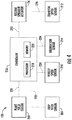
- FIG. 4 a schematic view of one embodiment of a system 100 for determining the residue yield of plant material being harvested by an agricultural harvester is illustrated in accordance with aspects of the present subject matter.
- the system 100 will be described herein with reference to the harvester 10 and header 100 described above with reference to FIGS 1 through 3 .
- the disclosed system 100 may generally be utilized with harvesters having any other suitable harvester configuration and/or harvesting implements having any other suitable implement configuration.
- the system 200 may include various components of the harvester 10.
- the system 200 may include the plant yield sensor(s) 202.
- the system 200 may, in one embodiment, include one plant yield sensor 202 provided in operative association with the first lateral conveyor 106 of the header 100 and another plant yield sensor 202 provided in operative association with the second lateral conveyor 108 of the header 100.
- the system 200 may include one plant yield sensor 202 provided in operative association with the central conveyor 110 of the header 100.
- the system 200 may include one plant yield sensor 202 provided in operative association with the feeder conveyor 50.
- the system 200 may include any other suitable number of plant yield sensors 202.
- system 200 may include the crop yield sensor 204, the vehicle speed sensor 210, the conveyor speed sensor 212, and/or the orientation sensor 214 described above with reference to FIGS. 1-3 . Additionally, the system 200 may the residue spreader actuator 74 of the residue spreader 72 ( FIG. 1 ). However, it should be appreciated that, in alternative embodiments, the system 200 may include any other suitable components of the harvester 10.
- the system 200 may also include a controller 216 configured to electronically control the operation of one or more components of the harvester 10.
- the controller 216 may comprise any suitable processor-based device known in the art, such as a computing device or any suitable combination of computing devices.
- the controller 216 may include one or more processor(s) 218 and associated memory device(s) 220 configured to perform a variety of computer-implemented functions.
- processor refers not only to integrated circuits referred to in the art as being included in a computer, but also refers to a controller, a microcontroller, a microcomputer, a programmable logic controller (PLC), an application specific integrated circuit, and other programmable circuits.
- PLC programmable logic controller
- the memory device(s) 220 of the controller 216 may generally comprise memory element(s) including, but not limited to, a computer readable medium (e.g., random access memory (RAM)), a computer readable non-volatile medium (e.g., a flash memory), a floppy disk, a compact disc-read only memory (CD-ROM), a magneto-optical disk (MOD), a digital versatile disc (DVD) and/or other suitable memory elements.
- RAM random access memory
- a computer readable non-volatile medium e.g., a flash memory
- CD-ROM compact disc-read only memory
- MOD magneto-optical disk
- DVD digital versatile disc
- Such memory device(s) 220 may generally be configured to store suitable computer-readable instructions that, when implemented by the processor(s) 218, configure the controller 216 to perform various computer-implemented functions, such as one or more aspects of the method 300 described below with reference to FIG. 6 .
- the controller 216 may also include various other suitable
- controller 216 may correspond to an existing controller of the harvester 10 or the controller 216 may correspond to a separate processing device.
- the controller 216 may form all or part of a separate plug-in module that may be installed within the harvester 10 to allow for the disclosed system and method to be implemented without requiring additional software to be uploaded onto existing control devices of the harvester 10.
- the controller 216 may be configured to determine the weight of plant materials being ingested by or otherwise entering the harvester 10. Specifically, as shown in FIG. 4 , the controller 216 may be communicatively coupled to the plant yield sensor(s) 202 via a wired or wireless connection to allow measurement signals (e.g., indicated by dashed line 222 in FIG. 4 ) to be transmitted from the plant yield sensor(s) 202 to the controller 216.
- the controller 216 may include a look-up table or suitable mathematical formula stored within its memory 220 that correlates the sensor measurements to the amount of the plant materials entering the harvester 10.
- the controller 216 may be configured to sum the amounts of plant materials determined based on measurement signals 222 received from each sensor 202.
- the controller 216 may be configured to determine the weight of crop materials removed from the ingested plant materials by the plant processing system 32. Specifically, as shown in FIG. 4 , the controller 216 may be communicatively coupled to the crop yield sensor 204 via a wired or wireless connection to allow measurement signals 222 to be transmitted from the crop yield sensor 204 to the controller 216. For instance, the controller 216 may include a look-up table or suitable mathematical formula stored within its memory 220 that correlates the sensor measurements to the amount of the crop materials entering the crop tank 16.
- such look-up table or mathematical formula may correlate the crop flow rate measurements (e.g., from the crop flow sensing device 206) and the crop moisture measurements (e.g., from crop moisture sensing device 208) to the amount of the crop materials entering the crop tank 16.
- the controller 216 may be configured to determine the speed at which the harvester 10 is moved in the direction of travel 12. Specifically, as shown in FIG. 4 , the controller 216 may be communicatively coupled to the vehicle speed sensor 210 via a wired or wireless connection to allow measurement signals (e.g., as indicated by dashed lines 224 in FIG. 4 ) to be transmitted from the vehicle speed sensor 210 to the controller 216. For instance, the controller 216 may include a look-up table or suitable mathematical formula stored within its memory 220 that correlates the sensor measurements to the vehicle speed of the harvester 10.
- the controller 216 may also be configured to determine the speed of one or more of the conveyors 50, 206, 208, 210.
- the controller 216 may be communicatively coupled to the conveyor speed sensor(s) 212 via a wired or wireless connection to allow measurement signals 224 to be transmitted from the conveyor speed sensor(s) 212 to the controller 216.
- the controller 216 may include a look-up table or suitable mathematical formula stored within its memory 220 that correlates the sensor measurements to the conveyor speed(s) of the conveyors 50, 206, 208, 210.
- the controller 216 may be configured to determine vertical movement of the harvester 10 relative to the ground 26. Specifically, as shown in FIG. 4 , the controller 216 may be communicatively coupled to the vehicle orientation sensor 214 via a wired or wireless connection to allow measurement signals 224 to be transmitted from the orientation sensor 214 to the controller 216. For instance, the controller 216 may include a look-up table or suitable mathematical formula stored within its memory 220 that correlates the sensor measurements to the vertical movement of the harvester 10.
- the controller 216 may be further configured to filter one or more components of the measurement signals 224 received from plant yield sensor(s) 202 and/or the crop yield sensor 204 before determining the associated plant and crop yields.
- Such measurement signal components may generally be associated with the operation of the harvester 10 and may impact the accuracy of the plant and crop yield determinations.
- such measurement signal components may include the speed at which the harvester 10 moves in the direction of travel, the speed of one or more of the conveyors 50, 106, 108, 110, and/or the vertical movement of the harvester 10 relative to the ground 26.
- the controller 216 may use one or more suitable filtering techniques, such as one or more software-based filters (e.g., suitable algorithms or formulas) stored within its memory 220, which filter or remove such components from the measurement signals 224.
- suitable filtering techniques may include high pass filtering, low pass filtering, band pass filtering, Butterworth filtering, and/or or combinations of such filtering techniques.
- the controller 216 may be configured to determine the plant and crop yields based on the raw measurement signals 224 received from the plant and crop yield sensors 202, 204.
- the controller 216 may be configured to determine a residue yield value by comparing the determined plant and crop yields. For example, in one embodiment, the controller 216 may be configured to subtract the determined weight of the crop materials entering the crop tank from the determined overall weight of the plant materials entering the header, with the difference therebetween being indicative of the residue yield. However, it should be appreciated that, in alternative embodiments, the controller 216 may be configured to determine the residue yield in any other suitable manner from the determined plant and crop yields.
- the monitored residue yield value of may correspond to an instantaneous value of the amount of the residue being discharged by the harvester 10. More specifically, as is generally understood, the amount of residue present in the plant materials produced by the standing crop 14 may vary as the harvester 10 is moved across the field.
- the controller 216 may be configured to continuously receive the measurement signals 222 from the plant and crop yield sensors 202, 204 as the harvester 10 is moved through the field. As such, the controller 216 may be configured to continuously update the determined residue yield value based on the subsequently received measurement signals 222.
- the controller 216 may be configured to create a residue yield map based on the determined amount of residue being discharged by the harvester 10.
- the residue yield map may provide an indication of the amount of residue present at one or more geographical or physical location within the field.
- the controller 216 may be configured to associate the determined residue yield being discharged by the harvester 10 with the current location or position of the harvester 10 (e.g., as determined by a GPS receiver or other location sensor (not shown)) within the field.
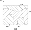
- FIG. 5 illustrates an example plant yield map 226 in accordance with aspects of the present subject matter.
- the determined residue yield value may vary at different locations within the field.
- regions 228 of the field may have a greater determined residue yield value than regions 230 of the field.
- the regions 228, 230 may be depicted with different colors or other visual indicators indicative of their varying determined residue yield values.
- the regions 228 may be identified by red, while the regions 230 may be identified by yellow.
- the colors corresponding to the various determined residue yield values in the map 226 of FIG. 5 may be indicative of the determined residue yield values associated with those particular locations within the field. For example, in one embodiment, low determined residue yield values may be associated with yellow, and high determined residue yield values may be associated with red.
- the controller 216 may also be configured to initiate a control action associated with adjusting one or more operating parameters of the harvester 10 based on the determined residue yield value(s). More specifically, as mentioned above, the monitored amount of residue discharged from the harvester 10 may vary throughout the field. As such, in several embodiments, the controller 216 may be configured to adjust one or more of the harvester's operating parameters based on variations in the determined residue yield value over time as the harvester 10 is moved through the field. For example, when the determined residue yield value increases, the controller 216 may be configured to adjust one or more operating parameters in a manner that permits the harvester 10 to increase the area over which the residue is spread. Conversely, when the determined residue yield value decreases, the controller 216 may be configured to adjust one or more operating parameters in a manner that permits the harvester 10 to decrease the area over which the residue is spread.
- the controller 216 may be configured to adjust one or more operating parameters associated with the residue spreader 72 based on the determined residue yield. Specifically, as shown in FIG. 4 , the controller 216 may be communicatively coupled to the actuator 74 of the residue spreader 72 via a wired or wireless connection to allow control signals (e.g., indicated by dashed lines 232 in FIG. 4 ) to be transmitted from the controller 216 to the residue spreader actuator 74. Such control signals 232 may be configured to instruct the residue spreader actuator 74 to increase the speed at which the residue spreader discs rotate to change the spread width of the residue discharged from the harvester 10.
- control signals 232 may be configured to instruct the residue spreader actuator 74 to increase the speed at which the residue spreader discs rotate to change the spread width of the residue discharged from the harvester 10.
- control signals 232 may instruct the residue spreader actuator 74 to increase the speed of the discs such that the spread width of the residue is increased. Conversely, when the determined residue yield amount value decreases, the control signals 232 may instruct the residue spreader actuator 74 to decrease the speed of the discs such that the spread width of the residue is decreased.
- the controller 216 may be configured to transmit control signals 232 to any other suitable component of the harvester 10 such that the spread width of the residue discharged from of the harvester 10 is adjusted.
- FIG. 6 a flow diagram of one embodiment of a method 300 for determining the residue yield of plant material being harvested by an agricultural harvester is illustrated in accordance with aspects of the present subject matter.
- the method 300 will be described herein with reference to the agricultural harvester 10, the header 100, and the system 200 described above with reference to FIGS. 1 through 5 .
- the disclosed method 300 may generally be utilized to determine the residue yield of plant material being harvested by any harvester having any suitable harvester configuration and/or any harvesting implement having any suitable implement configuration and/or in connection with any system having any suitable system configuration.
- FIG. 6 a flow diagram of one embodiment of a method 300 for determining the residue yield of plant material being harvested by an agricultural harvester is illustrated in accordance with aspects of the present subject matter.
- the method 300 will be described herein with reference to the agricultural harvester 10, the header 100, and the system 200 described above with reference to FIGS. 1 through 5 .
- the disclosed method 300 may generally be utilized to determine the residue yield of plant material being harvested by any harvester having any suitable harvester configuration
- the method 300 may include controlling, with a computing device, the operation of the agricultural harvester such that a harvesting implement of the harvester ingests a quantity of plant materials from a field.
- the controller 216 may be configured to control the operation of the header 100 of the harvester 10 such that the header 100 ingests plant materials from the field.
- the method 300 may include controlling, with a computing device, the operation of the agricultural harvester such that a plant processing system of the harvester processes the quantity of harvested plant materials ingested by harvesting implement.
- the controller 216 may be configured to control the operation of the plant processing system 32 of the harvester 10 such that the plant processing system 32 processes the harvested plant materials ingested by harvesting implement 100, thereby separating the crop materials from the associated residue.
- the method 300 may include determining, with the computing device, a weight of the quantity of plant materials being ingested by the harvesting implement based on data received from a plant yield sensor.
- the controller 216 may be communicatively coupled to the plant yield sensor(s) 202 configured to capture data 222 indicative of the weight of plant materials currently being ingested by the harvester 10.
- data 222 transmitted from the plant yield sensor(s) 202 may be received by the controller 216 and subsequently analyzed and/or processed to determine the weight of plant materials being ingested.
- the method 300 may include determining, with the computing device, the weight of a quantity of crop removed from the quantity of harvested plant materials based on data received from a crop yield sensor.
- the controller 216 may be communicatively coupled to the crop yield sensor 204 configured to capture data 222 indicative of the weight of crop materials separated from the harvested plant materials by the plant processing system 32 of the harvester 10.
- data 222 transmitted from the crop yield sensor 204 may be received by the controller 216 and subsequently analyzed and/or processed to determine the weight of crop materials removed from the plant materials.
- the method 300 may include determining, with the computing device, a residue yield value by comparing the determined weight of the quantity of plant materials and the determined weight of the quantity of crop materials. For instance, as described above, the controller 216 may be configured to subtract the determined weight of the crop materials from the determined weight of plant materials, with the difference therebetween being indicative of the residue yield.
Landscapes
- Life Sciences & Earth Sciences (AREA)
- Environmental Sciences (AREA)
- Management, Administration, Business Operations System, And Electronic Commerce (AREA)
- Harvesting Machines For Root Crops (AREA)
- Harvester Elements (AREA)
Abstract
Description
- The present disclosure generally relates to agricultural harvesters and, more particularly, to systems and methods for determining the residue yield of plant materials being harvested by an agricultural harvester.
- A harvester is an agricultural machine used to harvest and process crops. For instance, a combine harvester may be used to harvest grain crops, such as wheat, oats, rye, barley, corn, soybeans, and flax or linseed. In general, the objective is to complete several processes, which traditionally were distinct, in one pass of the machine over a particular part of the field. In this regard, most harvesters are equipped with a detachable harvesting implement, such as a header, which cuts and collects plant materials from the field. The harvester also includes a plant processing system, which performs various processing operations (e.g., threshing, separating, etc.) to separate the crops from the other plant materials received from the harvesting implement. The separated crop materials are stored in a crop tank of the harvester, while the remaining residue is discharged from harvester as the harvester is moved across the field.
- The yield or amount of the residue discharged from the harvester may impact later farming operations within the field. Specifically, farmers may adjust their tillage, fertilizing, and/or drainage practices based on the amount of residue present within the field to maximize crop growth and productivity. For example, farmers may choose to perform additional tillage on portion of the field in which high levels of residue are present. However, while current harvesters are configured to detect the yield of crop materials entering the crop tank, such harvesters are unable to determine the yield of residue discharged from the harvester.
- Accordingly, an improved system and method for determining the residue yield of plant materials being harvested by an agricultural harvester would be welcomed in the technology.
- Aspects and advantages of the technology will be set forth in part in the following description, or may be obvious from the description, or may be learned through practice of the technology.
- In one aspect, the present subject matter is directed to an agricultural harvester. The harvester may include a harvesting implement configured to ingest a quantity of plant materials from a field and a plant processing system configured to process the quantity of harvested plant materials ingested by harvesting implement. The harvester may also include a system for determining a residue yield of the plant materials ingested by the harvesting implement. The system may include a plant yield sensor configured to detect a parameter associated with a weight of the harvested plant materials being ingested by the harvesting implement. Moreover, the system may include a crop yield sensor configured to detect a parameter associated with a weight of a quantity of crop materials removed from the quantity of harvested plant materials by the plant processing system. Furthermore, the system may include a controller communicatively coupled to the plant and the crop yield sensors. The controller may be configured to determine the weight of the quantity of plant materials being ingested by the harvesting implement based on measurement signals received from the plant yield sensor. The controller may also be configured to determine the weight of the quantity of crop materials removed from the quantity of harvested plant materials based on measurement signals received from the crop yield sensor. Additionally, the controller may also be configured to determine a residue yield value by comparing the determined weight of the quantity of plant materials and the determined weight of the quantity of crop materials.
- In another aspect, the present subject matter is directed to a method for determining a residue yield of plant material being harvested by an agricultural harvester. The agricultural harvester may include a harvesting implement configured to ingest a quantity of plant materials from a field and a plant processing system configured to process the quantity of harvested plant materials ingested by harvesting implement. The method may include controlling, with a computing device, an operation of the agricultural harvester such that a harvesting implement of the harvester ingests a quantity of plant materials from a field and a plant processing system of the harvester processes the quantity of harvested plant materials ingested by harvesting implement. The method may also include determining, with the computing device, a weight of the quantity of plant materials being ingested by the harvesting implement based on data received from the plant yield sensor. Furthermore, the method may include determining, with the computing device, a weight of a quantity of crop removed from the quantity of harvested plant materials based on data received from the crop yield sensor. Additionally, the method may include determining, with the computing device, a residue yield value by comparing the determined weight of the quantity of plant materials and the determined weight of the quantity of crop.
- In a further aspect, the present subject matter is directed to a system for determining a residue yield of the plant materials ingested by a harvesting implement of an agricultural harvester. The system may include a plant yield sensor configured to detect a parameter associated with a weight of the harvested plant materials being ingested by the harvesting implement. The system may also include a crop yield sensor configured to detect a parameter associated with a weight of a quantity of crop materials removed from the quantity of harvested plant materials by a plant processing system of the agricultural harvester. Furthermore, the system may include a controller communicatively coupled to the plant and the crop yield sensors. The controller may be configured to determine the weight of the quantity of plant materials being ingested by the harvesting implement based on measurement signals received from the plant yield sensor. The controller may also be configured to determine the weight of the quantity of crop materials removed from the quantity of harvested plant materials based on measurement signals received from the crop yield sensor. Additionally, the controller may be configured to determine a residue yield value by comparing the determined weight of the quantity of plant materials and the determined weight of the quantity of crop materials.
- These and other features, aspects and advantages of the present technology will become better understood with reference to the following description and appended claims. The accompanying drawings, which are incorporated in and constitute a part of this specification, illustrate embodiments of the technology and, together with the description, serve to explain the principles of the technology.
- A full and enabling disclosure of the present technology, including the best mode thereof, directed to one of ordinary skill in the art, is set forth in the specification, which makes reference to the appended figures, in which:
-
FIG. 1 illustrates a side view of one embodiment of an agricultural harvester in accordance with aspects of the present subject matter; -
FIG. 2 illustrates a top view of one embodiment of a harvesting implement of an agricultural harvester in accordance with aspects of the present subject matter; -
FIG. 3 illustrates a side view of one embodiment of a conveyor of harvesting implement of an agricultural harvester in accordance with aspects of the present subject matter, particularly illustrating various sensors provided in operative association with the conveyor; -
FIG. 4 illustrates a schematic view of one embodiment of a system for determining the residue yield of plant materials being harvested by an agricultural harvester in accordance with aspects of the present subject matter; -
FIG. 5 illustrates an example residue yield map in accordance with aspects of the present subject matter; and -
FIG. 6 illustrates a flow diagram of one embodiment of a method for determining the residue yield of plant materials being harvested by an agricultural harvester in accordance with aspects of the present subject matter. - Repeat use of reference characters in the present specification and drawings is intended to represent the same or analogous features or elements of the present technology.
- Reference now will be made in detail to embodiments of the invention, one or more examples of which are illustrated in the drawings. Each example is provided by way of explanation of the invention, not limitation of the invention. In fact, it will be apparent to those skilled in the art that various modifications and variations can be made in the present invention without departing from the scope or spirit of the invention. For instance, features illustrated or described as part of one embodiment can be used with another embodiment to yield a still further embodiment. Thus, it is intended that the present invention covers such modifications and variations as come within the scope of the appended claims and their equivalents.
- In general, the present subject matter is directed to systems and methods for determining the residue yield of plant materials being harvested by an agricultural harvester. Specifically, in several embodiments, a controller of the disclosed system may be configured to determine the weight of a quantity of plant materials being ingested by a harvesting implement of the harvester based on measurement signals received from one or more plant yield sensors. For example, in one embodiment, the plant yield sensor(s) may be provided in operative association with one or more conveyors of the harvester implement. In such embodiment, the plant yield sensor(s) may be configured to detect the weight of the harvested plant materials being transported by the conveyor(s). Moreover, the controller may also be configured to determine the weight of the quantity of crop materials removed from the harvested plant materials by a plant processing system of the harvester based on measurement signals received from a crop yield sensor. Thereafter, the controller may be configured to determine the residue yield value of the ingested plant materials by comparing the determined weight of the plant materials and the determined weight of the separated crop materials.
- Referring now to the drawings,
FIG. 1 illustrates a partial sectional side view of one embodiment of anagricultural harvester 10 in accordance with aspects of the present subject matter. In general, theharvester 10 may be configured to be moved across a field in a direction of travel (e.g., as indicated by arrow 12) to harvest standingcrop 14. While traversing the field, theharvester 10 may be configured to intake and process harvested plant materials from the standingcrop 14, thereby separating the crop materials of the harvested plant materials from the associated residue. Thereafter, theharvester 10 may be configured to store the crop materials within acrop tank 16 of theharvester 10 and discharge the remaining residue from theharvester 10. Furthermore, theharvester 10 may be configured to unload the crop materials stored within thecrop tank 16 into a crop cart (not shown) or other suitable crop container. - As shown, in one embodiment, the
harvester 10 may be configured as an axial-flow type combine, wherein the harvested plant materials are threshed and separated while being advanced by and along a longitudinally arrangedrotor 18. However, it should be appreciated that, in alternative embodiments, theharvester 10 may have any suitable harvester configuration. - The
harvester 10 may include a chassis ormain frame 20 configured to support and/or couple to various components of theharvester 10. For example, in several embodiments, theharvester 10 may include a pair of driven, ground-engagingfront wheels 22 and a pair of steerablerear wheels 24 that are coupled to theframe 20. As such, thewheels harvester 10 relative to aground surface 26 and move theharvester 10 in the forward direction oftravel 12 relative to theground surface 26. Furthermore, theharvester 10 may include an operator'splatform 28 having an operator'scab 30, aplant processing system 32, and thecrop tank 16 that are supported by theframe 20. As will be described below, theplant processing system 32 may be configured to perform various processing operations on the harvested plant materials as theplant processing system 32 operates to transfer the harvested plant materials received from a harvesting implement (e.g., header 100) of theharvester 10 through theharvester 10. Additionally, as is generally understood, theharvester 10 may include anengine 36 and atransmission 38 mounted on theframe 20. Thetransmission 38 may be operably coupled to theengine 36 and may provide variably adjusted gear ratios for transferring engine power to thewheels - Moreover, as shown in
FIG. 1 , theheader 100 and an associatedfeeder 40 of theplant processing system 32 may extend forward of theframe 20 and may be pivotally secured thereto for generally vertical movement. In general, thefeeder 40 may be configured to serve as support structure for theheader 100. As shown inFIG. 1 , thefeeder 40 may extend between afront end 42 coupled to theheader 100 and arear end 44 positioned adjacent to a threshing and separatingassembly 46 of theplant processing system 32. As is generally understood, therear end 44 of thefeeder 40 may be pivotally coupled to a portion of theharvester 10 to allow thefront end 42 of thefeeder 40 and, thus, theheader 100 to be moved upward and downward relative to theground 26 to set the desired harvesting or cutting height for theheader 100. - As the
harvester 10 is propelled forwardly over the field with the standingcrop 14, the plant materials are severed from the stubble by asickle bar 102 at the front of theheader 100 and delivered by aheader auger 104 to thefront end 42 of thefeeder 40. Afeeder conveyor 50 supported by afeeder frame 51 transports the harvested plant materials from thefront end 42 of thefeeder 40 to the threshing and separatingassembly 46. As is generally understood, the threshing and separatingassembly 46 may include acylindrical chamber 52 in which therotor 18 is rotated to thresh and separate the harvested plant materials received therein. That is, the harvested plant materials are rubbed and beaten between therotor 18 and the inner surfaces of thechamber 52, whereby the crop materials (e.g., grain, seed, or the like) are is loosened and separated from the straw of the plant materials. - The crop materials that have been separated by the threshing and separating
assembly 46 may fall onto acrop cleaning assembly 54 of theplant processing system 32. In general, thecrop cleaning assembly 54 may include a series ofpans 56 and associated sieves 58. As is generally understood, the separated crop materials may be spread out via oscillation of thepans 56 and/or thesieves 58 and may eventually fall through apertures defined in thesieves 58. Additionally, a cleaningfan 60 may be positioned adjacent to one or more of thesieves 58 to provide an air flow through thesieves 58 that remove chaff and other impurities from the crop materials. For instance, thefan 60 may blow the impurities off of the crop materials for discharge from theharvester 10 through the outlet of aresidue hood 62 positioned at the back end of theharvester 10. The cleaned crop materials passing through thesieves 58 may then fall into a trough of anauger 64, which may be configured to transfer the crop materials to anelevator 66 for delivery to thecrop tank 18. Additionally, in one embodiment, a pair oftank augers 68 at the bottom of thecrop tank 18 may be used to urge the cleaned crop materials sideways to an unloadingtube 70 for discharge from theharvester 10. - Moreover, in several embodiments, the
harvester 10 may include aresidue spreader 72 configured to discharge the residue (e.g., the straw, chaff, impurities, and/or the like) from theresidue hood 62 as theharvester 10 is moved across the field. For example, in one embodiment, thespreader 72 may include one or more spreader discs (not shown) configured to eject the residue from theresidue hood 62, with such disc(s) being driven by an associated actuator(s) 74 (e.g., an electric motor(s)). As will be described below, the actuator(s) 74 may be configured to adjust the spread width of the residue (e.g., the lateral width of the stream of residue) being discharged from theharvester 10. However, it should be appreciated thatresidue spreader 72 may have any other suitable configuration. - Furthermore, as shown in
FIG. 1 , aplant yield sensor 202 may be provided in operative association with thefeeder 40. As such, theplant yield sensor 202 may be configured to detect a parameter associated with the weight of the harvested plant materials being transported through thefeeder 40 from theheader 100 to the threshing and separatingassembly 46. For example, in one embodiment, theplant yield sensor 202 may correspond to a weight sensor provided in operative association with thefeeder conveyor 50, with such weight sensor being configured to detect the weight of the plant materials being transported by thefeeder conveyor 50. In another embodiment, theplant yield sensor 202 may correspond to a load cell provided in operative association with thefeeder frame 51, with such weight sensor being configured to detect the weight ofheader 100 and the plant materials present on within the 100. However, it should be appreciated that theplant yield sensor 202 may be provided in operative association with any other suitable component of thefeeder 40 and/or be correspond to any other suitable type of sensing device configured to detect any other suitable parameter associated with the weight of the harvested plant materials being transported by thefeeder 40. For example, in one embodiment, theplant yield sensor 202 may correspond to a torque sensor configured to detect the operating torque of one ormore rollers feeder conveyor 50. Furthermore, as will be described below, aplant yield sensor 202 may be provided in operative association with theheader 100 in addition to or as an alternative to theplant yield sensor 202 provided in operative association with thefeeder 40. - In several embodiments, the
harvester 10 may also include acrop yield sensor 204 configured to detect a parameter associated with the weight of crop materials removed from the harvested plant materials by theplant processing system 32. For example, as shown inFIG. 1 , in one embodiment, thecrop yield sensor 204 may be provided in operative association with thecrop tank 18. In such embodiment, thecrop yield sensor 204 may include a cropflow sensing device 206, such as a flow meter, configured to detect the flow rate of the crop materials being delivered to thecrop tank 18 by theelevator 66. Additionally, thecrop yield sensor 204 may include a cropmoisture sensing device 208, such as a humidity sensor, configured to detect the moisture present within the crop materials stored in thecrop tank 18. As will be described below, the flow rate and the moisture of the crop materials may collectively be indicative of the weight of the crop materials separated from the harvested plant materials. However, it should be appreciated that, in alternative embodiments, thecrop yield sensor 204 may correspond to and/or comprise any other suitable sensing device or combination of sensing devices configured to detect a parameter associated with the weight of crop materials removed from the harvested plant materials. Furthermore, thecrop yield sensor 204 may be provided in operative association with any other suitable component of theharvester 10, such as theelevator 66. - Additionally, the
harvester 10 may include one ormore sensors harvester 10. For example, theharvester 10 may include a vehicle speed sensor 210 (e.g., a Hall Effect sensor) configured to detect the speed of theharvester 10 in the direction oftravel 12. Moreover, theharvester 10 may include a feederconveyor speed sensor 212 configured to detect the speed thefeeder conveyor 50. The detected conveyor speed may be the rotational or linear speed of a belt of thefeeder conveyor 50. In this regard, thevehicle speed sensor 210 and/or the feederconveyor speed sensor 212 may correspond to Hall Effect sensors or any other suitable type of sensors configured to detect rotational speed. Furthermore, theharvester 10 may include anorientation sensor 214 configured to detect a parameter associated with the orientation of theharvester 10 relative to theground 26. For example, in one embodiment, thesensor 214 may be configured to detect vertical movement of theharvester 10 relative to theground 26, such as movement caused by field topography changes (e.g., bumps, depressions, and/or the like). As such, theorientation sensor 214 may correspond to a gyroscope, an inertial measurement unit (IMU), or any other suitable sensor configured to detect orientation changes. - Referring now to
FIG. 2 , a top view of one embodiment of theheader 100 described above with reference toFIG. 1 is illustrated in accordance with aspects of the present subject matter. As shown, in several embodiments, theheader 100 may be configured as a draperheader including conveyors feeder 40. However, it should be appreciated that, in alternative embodiments, theheader 100 may be configured as any other suitable type of header. - As shown in
FIG. 2 , theheader 100 may include aheader frame 112. In general, theframe 112 may extend along alongitudinal direction 114 between aforward end 116 and anaft end 118. Theframe 112 may also extend along alateral direction 120 between afirst side 122 and asecond side 124. In this respect, theframe 112 may be configured to support or couple to a plurality of components of theheader 100. For example, theconveyors FIG. 1 ) may be supported by theframe 112. Additionally, thesickle bar 102 may be supported by and/or coupled to theframe 112. - As indicated above, the
conveyors sickle bar 102 to thefeeder 40. For example, as shown inFIG. 2 , in one embodiment, laterally extending conveyors (e.g., a firstlateral conveyor 106 and a second lateral conveyor 108) may be positioned adjacent to the first andsecond sides header frame 112, respectively. In this regard, the firstlateral conveyor 106 may be configured to transport harvested plant materials laterally inward (e.g., as indicated byarrow 126 inFIG. 2 ) from thefirst side 122 of theframe 112 toward a laterallycentral portion 128 of theheader 100. Similarly, the secondlateral conveyor 108 may be configured to transport harvested plant materials laterally inward (e.g., as indicated byarrow 130 inFIG. 2 ) from thesecond side 124 of theframe 112 toward the laterallycentral portion 128. Additionally, acentral conveyor 110 may be positioned laterally between thelateral conveyors conveyor 110 is positioned at or proximate to the laterallycentral portion 128 of theheader 100. As such, thecentral conveyor 110 may be configured to transport the plant materials provided to the laterallycentral portion 128 of theheader 100 by thelateral conveyors front end 42 of the feeder 40 (e.g., as indicated byarrow 132 inFIG. 2 ). It should be appreciated that, in alternative embodiments, theheader 100 may include any other suitable number of conveyor belts, such as more or fewer than three conveyor belts. Furthermore, it should be appreciated that theheader 100 may be configured as any other suitable type of header. -
FIG. 3 illustrates a schematic view of one embodiment of a suitable configuration for one or more of theconveyors header 100 described above with reference toFIG. 2 in accordance with aspects of the present subject matter. As indicated above, theconveyors header frame 112. As shown inFIG. 3 , eachconveyor rollers conveyor belt 138 relative to theheader frame 112. As such, eachconveyor belt 138 may be configured to be wrapped around or otherwise engage the correspondingrollers conveyor belt 138 changes (e.g., reverses direction) assuch conveyor belt 138 engages or wraps around each correspondingrollers rollers conveyor belt 138 such that the harvested plant materials are moved in thecorresponding conveyer direction FIG. 2 ). It should be appreciated that, in other embodiments, eachconveyor opposed end rollers conveyor belt 138 positioned between therollers conveyor - As indicated above, in several embodiments, one or more
plant yield sensors 202 may be provided in operative association with theheader 100. As such, the plant yield sensor(s) 202 may be configured to detect a parameter(s) associated with the weight of the harvested plant materials being ingested by theheader 100. Specifically, in one embodiment, the plant yield sensor(s) 202 may correspond to a weight sensor(s), such as a load cell(s), provided in operative association with one or more of theconveyors conveyor conveyor belt 138 against the weight sensor(s). In one embodiment, as shown inFIG. 2 , oneplant yield sensor 202 may be provided in operative association with the firstlateral conveyor 106, and anotherplant yield sensor 202 may be provided in operative association with the secondlateral conveyor 108. In such embodiment, eachplant yield sensor 202 may be configured to detect the weight of the plant materials on itsrespective conveyor header 100 is detected. In another embodiment, a singleplant yield sensor 202 may be provided in operative association with thecentral conveyor 110 to detect the weight of all of the plant materials being ingested by theheader 100. However, it should be appreciated that the plant yield sensor(s) 202 may be provided in operative association with any other suitable component of theheader 100 and/or be correspond to any other suitable type of sensing device(s) configured to detect any other suitable parameter(s) associated with the weight of the harvested plant materials being ingested by theharvester 10. For example, in one embodiment, the plant yield sensor(s) 202 may correspond to a torque sensor(s) configured to detect the operating torque(s) of one ormore rollers conveyors - Additionally, in one embodiment, the
header 100 may include one or moreconveyor speed sensors 212 configured to detect the speed of one or more of theconveyors corresponding conveyor conveyor speed sensor 212 may correspond to a Hall Effect sensor or any other suitable type of sensing device configured to detect rotational speed. - It should be further be appreciated that the configurations of the
harvester 10 and theheader 100 described above and shown inFIGS. 1 through 3 are provided only to place the present subject matter in an exemplary field of use. Thus, it should be appreciated that the present subject matter may be readily adaptable to any manner of harvester and/or header configuration. - Referring now to
FIG. 4 , a schematic view of one embodiment of asystem 100 for determining the residue yield of plant material being harvested by an agricultural harvester is illustrated in accordance with aspects of the present subject matter. In general, thesystem 100 will be described herein with reference to theharvester 10 andheader 100 described above with reference toFIGS 1 through 3 . However, it should be appreciated by those of ordinary skill in the art that the disclosedsystem 100 may generally be utilized with harvesters having any other suitable harvester configuration and/or harvesting implements having any other suitable implement configuration. - As shown in
FIG. 4 , the system 200 may include various components of theharvester 10. For example, in several embodiments, the system 200 may include the plant yield sensor(s) 202. For example, as indicated above, the system 200 may, in one embodiment, include oneplant yield sensor 202 provided in operative association with the firstlateral conveyor 106 of theheader 100 and anotherplant yield sensor 202 provided in operative association with the secondlateral conveyor 108 of theheader 100. In another embodiment, the system 200 may include oneplant yield sensor 202 provided in operative association with thecentral conveyor 110 of theheader 100. In a further embodiment, the system 200 may include oneplant yield sensor 202 provided in operative association with thefeeder conveyor 50. However, it should be appreciated that the system 200 may include any other suitable number ofplant yield sensors 202. Furthermore, the system 200 may include thecrop yield sensor 204, thevehicle speed sensor 210, theconveyor speed sensor 212, and/or theorientation sensor 214 described above with reference toFIGS. 1-3 . Additionally, the system 200 may theresidue spreader actuator 74 of the residue spreader 72 (FIG. 1 ). However, it should be appreciated that, in alternative embodiments, the system 200 may include any other suitable components of theharvester 10. - In accordance with aspects of the present subject matter, the system 200 may also include a
controller 216 configured to electronically control the operation of one or more components of theharvester 10. In general, thecontroller 216 may comprise any suitable processor-based device known in the art, such as a computing device or any suitable combination of computing devices. Thus, in several embodiments, thecontroller 216 may include one or more processor(s) 218 and associated memory device(s) 220 configured to perform a variety of computer-implemented functions. As used herein, the term "processor" refers not only to integrated circuits referred to in the art as being included in a computer, but also refers to a controller, a microcontroller, a microcomputer, a programmable logic controller (PLC), an application specific integrated circuit, and other programmable circuits. Additionally, the memory device(s) 220 of thecontroller 216 may generally comprise memory element(s) including, but not limited to, a computer readable medium (e.g., random access memory (RAM)), a computer readable non-volatile medium (e.g., a flash memory), a floppy disk, a compact disc-read only memory (CD-ROM), a magneto-optical disk (MOD), a digital versatile disc (DVD) and/or other suitable memory elements. Such memory device(s) 220 may generally be configured to store suitable computer-readable instructions that, when implemented by the processor(s) 218, configure thecontroller 216 to perform various computer-implemented functions, such as one or more aspects of themethod 300 described below with reference toFIG. 6 . In addition, thecontroller 216 may also include various other suitable components, such as a communications circuit or module, one or more input/output channels, a data/control bus and/or the like. - It should be appreciated that the
controller 216 may correspond to an existing controller of theharvester 10 or thecontroller 216 may correspond to a separate processing device. For instance, in one embodiment, thecontroller 216 may form all or part of a separate plug-in module that may be installed within theharvester 10 to allow for the disclosed system and method to be implemented without requiring additional software to be uploaded onto existing control devices of theharvester 10. - In several embodiments, the
controller 216 may be configured to determine the weight of plant materials being ingested by or otherwise entering theharvester 10. Specifically, as shown inFIG. 4 , thecontroller 216 may be communicatively coupled to the plant yield sensor(s) 202 via a wired or wireless connection to allow measurement signals (e.g., indicated by dashedline 222 inFIG. 4 ) to be transmitted from the plant yield sensor(s) 202 to thecontroller 216. For instance, thecontroller 216 may include a look-up table or suitable mathematical formula stored within itsmemory 220 that correlates the sensor measurements to the amount of the plant materials entering theharvester 10. In embodiments in which the system 200 includesseparate sensors 202 provided in operative association with the laterally extendedheader conveyors controller 216 may be configured to sum the amounts of plant materials determined based onmeasurement signals 222 received from eachsensor 202. - Additionally, the
controller 216 may be configured to determine the weight of crop materials removed from the ingested plant materials by theplant processing system 32. Specifically, as shown inFIG. 4 , thecontroller 216 may be communicatively coupled to thecrop yield sensor 204 via a wired or wireless connection to allowmeasurement signals 222 to be transmitted from thecrop yield sensor 204 to thecontroller 216. For instance, thecontroller 216 may include a look-up table or suitable mathematical formula stored within itsmemory 220 that correlates the sensor measurements to the amount of the crop materials entering thecrop tank 16. In one embodiment, such look-up table or mathematical formula may correlate the crop flow rate measurements (e.g., from the crop flow sensing device 206) and the crop moisture measurements (e.g., from crop moisture sensing device 208) to the amount of the crop materials entering thecrop tank 16. - Additionally, in one embodiment, the
controller 216 may be configured to determine the speed at which theharvester 10 is moved in the direction oftravel 12. Specifically, as shown inFIG. 4 , thecontroller 216 may be communicatively coupled to thevehicle speed sensor 210 via a wired or wireless connection to allow measurement signals (e.g., as indicated by dashedlines 224 inFIG. 4 ) to be transmitted from thevehicle speed sensor 210 to thecontroller 216. For instance, thecontroller 216 may include a look-up table or suitable mathematical formula stored within itsmemory 220 that correlates the sensor measurements to the vehicle speed of theharvester 10. - Moreover, the
controller 216 may also be configured to determine the speed of one or more of theconveyors FIG. 4 , thecontroller 216 may be communicatively coupled to the conveyor speed sensor(s) 212 via a wired or wireless connection to allowmeasurement signals 224 to be transmitted from the conveyor speed sensor(s) 212 to thecontroller 216. For instance, thecontroller 216 may include a look-up table or suitable mathematical formula stored within itsmemory 220 that correlates the sensor measurements to the conveyor speed(s) of theconveyors - Furthermore, in one embodiment, the
controller 216 may be configured to determine vertical movement of theharvester 10 relative to theground 26. Specifically, as shown inFIG. 4 , thecontroller 216 may be communicatively coupled to thevehicle orientation sensor 214 via a wired or wireless connection to allowmeasurement signals 224 to be transmitted from theorientation sensor 214 to thecontroller 216. For instance, thecontroller 216 may include a look-up table or suitable mathematical formula stored within itsmemory 220 that correlates the sensor measurements to the vertical movement of theharvester 10. - In one embodiment, the
controller 216 may be further configured to filter one or more components of the measurement signals 224 received from plant yield sensor(s) 202 and/or thecrop yield sensor 204 before determining the associated plant and crop yields. Such measurement signal components may generally be associated with the operation of theharvester 10 and may impact the accuracy of the plant and crop yield determinations. For example, such measurement signal components may include the speed at which theharvester 10 moves in the direction of travel, the speed of one or more of theconveyors harvester 10 relative to theground 26. As such, thecontroller 216 may use one or more suitable filtering techniques, such as one or more software-based filters (e.g., suitable algorithms or formulas) stored within itsmemory 220, which filter or remove such components from the measurement signals 224. For example, such filtering techniques may include high pass filtering, low pass filtering, band pass filtering, Butterworth filtering, and/or or combinations of such filtering techniques. It should be appreciated that, in alternative embodiments, thecontroller 216 may be configured to determine the plant and crop yields based on the raw measurement signals 224 received from the plant andcrop yield sensors - In accordance with aspects of the present subject matter, the
controller 216 may be configured to determine a residue yield value by comparing the determined plant and crop yields. For example, in one embodiment, thecontroller 216 may be configured to subtract the determined weight of the crop materials entering the crop tank from the determined overall weight of the plant materials entering the header, with the difference therebetween being indicative of the residue yield. However, it should be appreciated that, in alternative embodiments, thecontroller 216 may be configured to determine the residue yield in any other suitable manner from the determined plant and crop yields. - In one embodiment, the monitored residue yield value of may correspond to an instantaneous value of the amount of the residue being discharged by the
harvester 10. More specifically, as is generally understood, the amount of residue present in the plant materials produced by the standingcrop 14 may vary as theharvester 10 is moved across the field. In such embodiment, thecontroller 216 may be configured to continuously receive the measurement signals 222 from the plant andcrop yield sensors harvester 10 is moved through the field. As such, thecontroller 216 may be configured to continuously update the determined residue yield value based on the subsequently received measurement signals 222. - Additionally, the
controller 216 may be configured to create a residue yield map based on the determined amount of residue being discharged by theharvester 10. In general, the residue yield map may provide an indication of the amount of residue present at one or more geographical or physical location within the field. As such, thecontroller 216 may be configured to associate the determined residue yield being discharged by theharvester 10 with the current location or position of the harvester 10 (e.g., as determined by a GPS receiver or other location sensor (not shown)) within the field. -
FIG. 5 illustrates an exampleplant yield map 226 in accordance with aspects of the present subject matter. As shown, the determined residue yield value may vary at different locations within the field. For instance, in theexample map 226 ofFIG. 5 , it may be assumed thatregions 228 of the field have a greater determined residue yield value thanregions 230 of the field. As such, theregions regions 228 may be identified by red, while theregions 230 may be identified by yellow. In this regard, it should be appreciated that the colors corresponding to the various determined residue yield values in themap 226 ofFIG. 5 may be indicative of the determined residue yield values associated with those particular locations within the field. For example, in one embodiment, low determined residue yield values may be associated with yellow, and high determined residue yield values may be associated with red. - In accordance with aspects of the present subject matter, the
controller 216 may also be configured to initiate a control action associated with adjusting one or more operating parameters of theharvester 10 based on the determined residue yield value(s). More specifically, as mentioned above, the monitored amount of residue discharged from theharvester 10 may vary throughout the field. As such, in several embodiments, thecontroller 216 may be configured to adjust one or more of the harvester's operating parameters based on variations in the determined residue yield value over time as theharvester 10 is moved through the field. For example, when the determined residue yield value increases, thecontroller 216 may be configured to adjust one or more operating parameters in a manner that permits theharvester 10 to increase the area over which the residue is spread. Conversely, when the determined residue yield value decreases, thecontroller 216 may be configured to adjust one or more operating parameters in a manner that permits theharvester 10 to decrease the area over which the residue is spread. - In several embodiments, the
controller 216 may be configured to adjust one or more operating parameters associated with theresidue spreader 72 based on the determined residue yield. Specifically, as shown inFIG. 4 , thecontroller 216 may be communicatively coupled to theactuator 74 of theresidue spreader 72 via a wired or wireless connection to allow control signals (e.g., indicated by dashedlines 232 inFIG. 4 ) to be transmitted from thecontroller 216 to theresidue spreader actuator 74. Such control signals 232 may be configured to instruct theresidue spreader actuator 74 to increase the speed at which the residue spreader discs rotate to change the spread width of the residue discharged from theharvester 10. For example, when the determined residue yield value increases, the control signals 232 may instruct theresidue spreader actuator 74 to increase the speed of the discs such that the spread width of the residue is increased. Conversely, when the determined residue yield amount value decreases, the control signals 232 may instruct theresidue spreader actuator 74 to decrease the speed of the discs such that the spread width of the residue is decreased. However, it should be appreciated that, in alternative embodiments, thecontroller 216 may be configured to transmitcontrol signals 232 to any other suitable component of theharvester 10 such that the spread width of the residue discharged from of theharvester 10 is adjusted. - Referring now to
FIG. 6 , a flow diagram of one embodiment of amethod 300 for determining the residue yield of plant material being harvested by an agricultural harvester is illustrated in accordance with aspects of the present subject matter. In general, themethod 300 will be described herein with reference to theagricultural harvester 10, theheader 100, and the system 200 described above with reference toFIGS. 1 through 5 . However, it should be appreciated by those of ordinary skill in the art that the disclosedmethod 300 may generally be utilized to determine the residue yield of plant material being harvested by any harvester having any suitable harvester configuration and/or any harvesting implement having any suitable implement configuration and/or in connection with any system having any suitable system configuration. In addition, althoughFIG. 6 depicts steps performed in a particular order for purposes of illustration and discussion, the methods discussed herein are not limited to any particular order or arrangement. One skilled in the art, using the disclosures provided herein, will appreciate that various steps of the methods disclosed herein can be omitted, rearranged, combined, and/or adapted in various ways without deviating from the scope of the present disclosure. - As shown in
FIG. 6 , at (302), themethod 300 may include controlling, with a computing device, the operation of the agricultural harvester such that a harvesting implement of the harvester ingests a quantity of plant materials from a field. For instance, as described above, thecontroller 216 may be configured to control the operation of theheader 100 of theharvester 10 such that theheader 100 ingests plant materials from the field. - Additionally, at (304), the
method 300 may include controlling, with a computing device, the operation of the agricultural harvester such that a plant processing system of the harvester processes the quantity of harvested plant materials ingested by harvesting implement. For instance, as described above, thecontroller 216 may be configured to control the operation of theplant processing system 32 of theharvester 10 such that theplant processing system 32 processes the harvested plant materials ingested by harvesting implement 100, thereby separating the crop materials from the associated residue. - Moreover, as shown in
FIG. 6 , at (306), themethod 300 may include determining, with the computing device, a weight of the quantity of plant materials being ingested by the harvesting implement based on data received from a plant yield sensor. For instance, as described above, thecontroller 216 may be communicatively coupled to the plant yield sensor(s) 202 configured to capturedata 222 indicative of the weight of plant materials currently being ingested by theharvester 10. As such,data 222 transmitted from the plant yield sensor(s) 202 may be received by thecontroller 216 and subsequently analyzed and/or processed to determine the weight of plant materials being ingested. - Furthermore, at (308), the
method 300 may include determining, with the computing device, the weight of a quantity of crop removed from the quantity of harvested plant materials based on data received from a crop yield sensor. For instance, as described above, thecontroller 216 may be communicatively coupled to thecrop yield sensor 204 configured to capturedata 222 indicative of the weight of crop materials separated from the harvested plant materials by theplant processing system 32 of theharvester 10. As such,data 222 transmitted from thecrop yield sensor 204 may be received by thecontroller 216 and subsequently analyzed and/or processed to determine the weight of crop materials removed from the plant materials. - Additionally, as shown in
FIG. 6 , at (310), themethod 300 may include determining, with the computing device, a residue yield value by comparing the determined weight of the quantity of plant materials and the determined weight of the quantity of crop materials. For instance, as described above, thecontroller 216 may be configured to subtract the determined weight of the crop materials from the determined weight of plant materials, with the difference therebetween being indicative of the residue yield. - This written description uses examples to disclose the technology, including the best mode, and also to enable any person skilled in the art to practice the technology, including making and using any devices or systems and performing any incorporated methods. The patentable scope of the technology is defined by the claims, and may include other examples that occur to those skilled in the art. Such other examples are intended to be within the scope of the claims if they include structural elements that do not differ from the literal language of the claims, or if they include equivalent structural elements with insubstantial differences from the literal language of the claims.
Claims (15)
- A method (300) for determining a residue yield of plant material being harvested by an agricultural harvester (10), the agricultural harvester (10) including a harvesting implement (100) configured to ingest a quantity of plant materials from a field and a plant processing system (32) configured to process the quantity of harvested plant materials ingested by harvesting implement (100), the method (300) comprising controlling, with a computing device, an operation of the agricultural harvester (10) such that a harvesting implement (100) of the harvester (10) ingests a quantity of plant materials from a field and a plant processing system (32) of the harvester (10) processes the quantity of harvested plant materials ingested by harvesting implement (100), the method (300) being characterized by:determining, with the computing device, a weight of the quantity of plant materials being ingested by the harvesting implement (100) based on data received from a plant yield sensor (202);determining, with the computing device, a weight of a quantity of crop removed from the quantity of harvested plant materials based on data received from a crop yield sensor (204); anddetermining, with the computing device, a residue yield value by comparing the determined weight of the quantity of plant materials and the determined weight of the quantity of crop.
- The method (300) as in claim 1, wherein the determined residue yield value corresponds to an instantaneous residue yield value, the method (300) further comprising:
continuously updating, with the computing device, the determined residue yield value based on the data received from the plant and crop yield sensors (202, 204). - The method (300) as in any preceding claim, further comprising:
initiating, with the computing device, a control action associated with adjusting an operating parameter of the agricultural harvester (10) based on the determined residue yield value. - The method (300) as in any preceding claim, further comprising:
adjusting, with the computing device, the operating parameter based on variations in the residue yield value with time as the agricultural harvester (10) is moved through the field. - The method (300) as in any preceding claim, further comprising:
filtering, with the computing device, a component of the data associated with an operation of the agricultural harvester (10) from the data received from plant yield sensor (202). - A system (200) for determining a residue yield of the plant materials ingested by a harvesting implement (100) of an agricultural harvester (10), the system (200) comprising a plant yield sensor (202) configured to detect a parameter associated with a weight of the harvested plant materials being ingested by the harvesting implement (100), the system (200) further comprising a crop yield sensor (204) configured to detect a parameter associated with a weight of a quantity of crop materials removed from the quantity of harvested plant materials by a plant processing system (32) of the agricultural harvester (10), the system (200) further comprising a controller (216) communicatively coupled to the plant and the crop yield sensors (202, 204), the system (200) being characterized by the controller (216) being configured to:determine the weight of the quantity of plant materials being ingested by the harvesting implement (100) based on measurement signals (222) received from the plant yield sensor (202);determine the weight of the quantity of crop materials removed from the quantity of harvested plant materials based on measurement signals (222) received from the crop yield sensor (204); anddetermine a residue yield value by comparing the determined weight of the quantity of plant materials and the determined weight of the quantity of crop materials.
- The system (200) as in claim 6, wherein the plant yield sensor (202) is provided in operative association with at least one of the harvesting implement (100) or a feeder (40) of the agricultural harvester (10).
- The system (200) as in any of claims 6 or 7, wherein the plant yield sensor (202) is provided in operative association with at least one of a harvesting implement conveyor (106, 108, 110), a feeder conveyor (50), or a feeder frame (51).
- The system (200) as in any of claims 6 through 8, wherein the plant yield sensor (202) corresponds to a weight sensor configured to detect the weight of the harvested plant materials present on the harvesting implement conveyor (106, 108, 110) or the feeder conveyor (50).
- The system (200) as in any of claims 6 through 9, wherein the determined residue yield value corresponds to an instantaneous residue yield value, the controller (216) being further configured to continuously update the determined residue yield value based on the measurement signals (222) received from the plant and crop yield sensors (202, 204).
- The system (200) as in any of claims 6 through 10, wherein the controller (216) is further configured to initiate a control action associated with adjusting an operating parameter of the agricultural harvester (10) based on the determined residue yield value.
- The system (200) as in any of claims 6 through 11, wherein the operating parameter corresponds to a spread width of residue being discharged by the agricultural harvester (10).
- The system (200) as in any of claims 6 through 12, wherein the controller (216) is further configured to adjust the operating parameter based on variations in the residue yield value with time as the agricultural harvester (10) is moved through a field.
- The system (200) as in any of claims 6 through 13, wherein the controller (216) is further configured to filter a component of the measurement signals (222) associated with an operation of the agricultural harvester (10) from the measurement signals (222) received from the plant yield sensor (202).
- The system (200) as in any of claims 6 through 14, wherein the component corresponds to at least one of a speed of the agricultural harvester (10) relative to a field, a vertical movement of the agricultural harvester (10) relative to the field, a speed of a conveyor (106, 108, 110) of the harvesting implement (100), or a speed of a conveyor (50) of a feeder (40).
Applications Claiming Priority (1)
| Application Number | Priority Date | Filing Date | Title |
|---|---|---|---|
| US16/026,158 US10820504B2 (en) | 2018-07-03 | 2018-07-03 | System and method for determining the residue yield of plant materials harvested by an agricultural harvester |
Publications (2)
| Publication Number | Publication Date |
|---|---|
| EP3590320A1 true EP3590320A1 (en) | 2020-01-08 |
| EP3590320B1 EP3590320B1 (en) | 2024-12-18 |
Family
ID=67137615
Family Applications (1)
| Application Number | Title | Priority Date | Filing Date |
|---|---|---|---|
| EP19183212.0A Active EP3590320B1 (en) | 2018-07-03 | 2019-06-28 | System for determining the residue yield of plant materials harvested by an agricultural harvester |
Country Status (2)
| Country | Link |
|---|---|
| US (1) | US10820504B2 (en) |
| EP (1) | EP3590320B1 (en) |
Cited By (1)
| Publication number | Priority date | Publication date | Assignee | Title |
|---|---|---|---|---|
| US20210195839A1 (en) * | 2019-12-30 | 2021-07-01 | Agco Corporation | Methods and systems for measuring organic material throughput data of harvested crops |
Families Citing this family (8)
| Publication number | Priority date | Publication date | Assignee | Title |
|---|---|---|---|---|
| DE102018103373A1 (en) * | 2018-02-15 | 2019-08-22 | Claas Selbstfahrende Erntemaschinen Gmbh | Combine harvester and method for its operation |
| DE102018212075A1 (en) * | 2018-07-19 | 2020-01-23 | Deere & Company | Combine harvester with an inclined conveyor with an actuator-adjustable lower deflection roller |
| US11930737B2 (en) * | 2019-12-24 | 2024-03-19 | Cnh Industrial America Llc | Self-propelled windrower with yield monitoring based on merger load |
| US11744179B2 (en) * | 2020-03-11 | 2023-09-05 | Deere & Company | Accumulator contents detection system for harvester |
| GB202108227D0 (en) * | 2021-06-09 | 2021-07-21 | Agco Int Gmbh | Residue spread mapping |
| US12477984B2 (en) | 2022-07-29 | 2025-11-25 | Cnh Industrial America Llc | Agricultural system and method for determining header throughput of a harvester |
| CN115968638B (en) * | 2023-01-17 | 2025-04-18 | 中国铁建重工集团股份有限公司 | Yield measurement method and system based on agricultural harvester, agricultural harvester |
| US12616098B2 (en) * | 2023-09-11 | 2026-05-05 | Deere & Company | System and method to control crop loss in a windrower implement |
Citations (5)
| Publication number | Priority date | Publication date | Assignee | Title |
|---|---|---|---|---|
| EP0958729A1 (en) * | 1998-05-22 | 1999-11-24 | New Holland Belgium N.V. | Harvester with crop flow rate sensor |
| EP2732693A2 (en) * | 2012-11-16 | 2014-05-21 | CNH Industrial Belgium nv | System and method for conveying agricultural material in a harvester |
| US20150327440A1 (en) * | 2014-05-16 | 2015-11-19 | Deere And Company | Multi-sensor crop yield determination |
| EP3095314A1 (en) * | 2015-05-20 | 2016-11-23 | Deere & Company | Sectional yield measurement on a row independent harvesting head |
| EP3242257A1 (en) * | 2016-05-02 | 2017-11-08 | Deere & Company | Method and arrangement for optimising operating parameters of a harvesting machine |
Family Cites Families (18)
| Publication number | Priority date | Publication date | Assignee | Title |
|---|---|---|---|---|
| US5318475A (en) | 1992-06-19 | 1994-06-07 | Case Corporation | Apparatus for measuring mass flow of grain in a harvesting machine |
| DE19606601C2 (en) | 1996-02-22 | 2000-01-27 | Franz Kleine Agrartechnik Gmbh | Device for picking up root crops with at least one conveyor |
| FR2768222B1 (en) | 1997-09-05 | 1999-10-08 | Pellenc Sa | ON-BOARD AND CONTINUOUS HARVEST WEIGHING DEVICE AND METHOD, AND HARVESTING MACHINES USING THE SAME |
| US5959257A (en) | 1998-04-15 | 1999-09-28 | Harvestmaster, Inc. | System for weighing material on a conveyor |
| US6525276B1 (en) | 1998-08-07 | 2003-02-25 | The University Of Georgia Research Foundation, Inc. | Crop yield monitoring system |
| US6272819B1 (en) | 1998-11-17 | 2001-08-14 | Case Corporation | Sugar cane yield monitor |
| DE19903471C1 (en) | 1999-01-29 | 2000-06-08 | Deere & Co | Crop machine throughput measurement arrangement derives throughput from distance between pre-baling rollers and crop speed, corrects for displacement force on pre-baling roller |
| US6431981B1 (en) | 1999-06-30 | 2002-08-13 | Wisconsin Alumni Research Foundation | Yield monitor for forage crops |
| US6951514B1 (en) | 2001-03-20 | 2005-10-04 | Deere & Company | Throughput control for combines using feederhouse signal |
| DE102008017671B4 (en) | 2008-04-08 | 2020-09-10 | Deere & Company | Measurement arrangement for mass throughput recording with mass and volume measurement and mass density determination based on this as well as mass throughput specification for small throughputs based on the last mass density recorded |
| DE102008043716B4 (en) | 2008-11-13 | 2012-06-21 | Deere & Company | Device and method for recording the stock density of plants in a field |
| US8735745B2 (en) | 2008-12-12 | 2014-05-27 | Hector Claudio Rossi | Device for continuously weighing a flowing bulk material exiting a conveyor |
| DE102009005873B4 (en) | 2009-01-20 | 2012-08-02 | Hochschule für Technik und Wirtschaft Dresden | Apparatus and method for the mass-related determination of the yield of cereal grains on harvesting machines |
| AU2011252751B2 (en) | 2010-05-10 | 2014-09-18 | Newcastle Innovation Limited | Parallel belt sampler |
| WO2012134723A2 (en) | 2011-03-31 | 2012-10-04 | Ag Leader Technology | Combine bin level monitoring system |
| DE102012017149A1 (en) | 2012-08-30 | 2014-03-06 | Class Selbstfahrende Erntemaschinen Gmbh | Harvester with crop supply control |
| US9372109B2 (en) | 2013-03-15 | 2016-06-21 | Raven Industires, Inc. | Harvester elevator in-flow weight sensor and methods for the same |
| US9410840B2 (en) | 2013-03-15 | 2016-08-09 | Raven Industries, Inc. | Multi-variable yield monitor and methods for the same |
-
2018
- 2018-07-03 US US16/026,158 patent/US10820504B2/en active Active
-
2019
- 2019-06-28 EP EP19183212.0A patent/EP3590320B1/en active Active
Patent Citations (5)
| Publication number | Priority date | Publication date | Assignee | Title |
|---|---|---|---|---|
| EP0958729A1 (en) * | 1998-05-22 | 1999-11-24 | New Holland Belgium N.V. | Harvester with crop flow rate sensor |
| EP2732693A2 (en) * | 2012-11-16 | 2014-05-21 | CNH Industrial Belgium nv | System and method for conveying agricultural material in a harvester |
| US20150327440A1 (en) * | 2014-05-16 | 2015-11-19 | Deere And Company | Multi-sensor crop yield determination |
| EP3095314A1 (en) * | 2015-05-20 | 2016-11-23 | Deere & Company | Sectional yield measurement on a row independent harvesting head |
| EP3242257A1 (en) * | 2016-05-02 | 2017-11-08 | Deere & Company | Method and arrangement for optimising operating parameters of a harvesting machine |
Cited By (2)
| Publication number | Priority date | Publication date | Assignee | Title |
|---|---|---|---|---|
| US20210195839A1 (en) * | 2019-12-30 | 2021-07-01 | Agco Corporation | Methods and systems for measuring organic material throughput data of harvested crops |
| US11874148B2 (en) * | 2019-12-30 | 2024-01-16 | Agco Corporation | Methods and systems for measuring organic material throughput data of harvested crops |
Also Published As
| Publication number | Publication date |
|---|---|
| US20200008350A1 (en) | 2020-01-09 |
| EP3590320B1 (en) | 2024-12-18 |
| BR102019013731A2 (en) | 2020-01-21 |
| US10820504B2 (en) | 2020-11-03 |
Similar Documents
| Publication | Publication Date | Title |
|---|---|---|
| EP3590320B1 (en) | System for determining the residue yield of plant materials harvested by an agricultural harvester | |
| EP3566565B1 (en) | System and method for monitoring the amount of plant materials entering an agricultural harvester | |
| US11006577B2 (en) | System and method for adjusting operating parameters of an agricultural harvester based on estimated crop volume | |
| US8662972B2 (en) | Method for uploading crop stored in a grain tank of a harvesting device | |
| EP3569050A1 (en) | Method and system for controlling the height of an agricultural implement relative to the ground | |
| US9968036B2 (en) | Methods for controlling a side-shaking mechanism in a combine | |
| US20210168991A1 (en) | System and method for controlling the direction of travel of a work vehicle based on an adjusted guidance line | |
| US20150080069A1 (en) | Arrangement for Loss Measurement in a Combine Harvester | |
| US12477985B2 (en) | Active deck plate opening | |
| US12457932B2 (en) | Sensing array for grain tank | |
| WO2020252295A1 (en) | Apparatus and method for monitoring grain content within a tailings system of an agricultural harvester | |
| EP4218393B1 (en) | System and method for controlling threshing assembly operation of an agricultural harvester | |
| EP3473074B1 (en) | Method and system for unloading harvested crop from an agricultural harvester | |
| US11696527B2 (en) | Multicrop harvesting | |
| EP4410086A1 (en) | Agricultural system and method for monitoring feeder throughput of a harvester | |
| EP4356711A1 (en) | Agricultural system and method for monitoring feeder throughput of a harvester | |
| US20250366397A1 (en) | System and method for controlling the operation of a harvesting implement of an agricultural harvester | |
| EP4413839B1 (en) | System and method for automatically controlling work vehicle operation | |
| BR102019013731B1 (en) | SYSTEM FOR DETERMINING THE RESIDUE YIELD OF PLANT MATERIALS INGESTED BY A HARVESTING IMPLEMENT OF AN AGRICULTURAL HARVESTER | |
| US20250268137A1 (en) | System and method for controlling the operation of an agricultural harvester |
Legal Events
| Date | Code | Title | Description |
|---|---|---|---|
| PUAI | Public reference made under article 153(3) epc to a published international application that has entered the european phase |
Free format text: ORIGINAL CODE: 0009012 |
|
| STAA | Information on the status of an ep patent application or granted ep patent |
Free format text: STATUS: THE APPLICATION HAS BEEN PUBLISHED |
|
| AK | Designated contracting states |
Kind code of ref document: A1 Designated state(s): AL AT BE BG CH CY CZ DE DK EE ES FI FR GB GR HR HU IE IS IT LI LT LU LV MC MK MT NL NO PL PT RO RS SE SI SK SM TR |
|
| AX | Request for extension of the european patent |
Extension state: BA ME |
|
| STAA | Information on the status of an ep patent application or granted ep patent |
Free format text: STATUS: REQUEST FOR EXAMINATION WAS MADE |
|
| 17P | Request for examination filed |
Effective date: 20200708 |
|
| RBV | Designated contracting states (corrected) |
Designated state(s): AL AT BE BG CH CY CZ DE DK EE ES FI FR GB GR HR HU IE IS IT LI LT LU LV MC MK MT NL NO PL PT RO RS SE SI SK SM TR |
|
| STAA | Information on the status of an ep patent application or granted ep patent |
Free format text: STATUS: EXAMINATION IS IN PROGRESS |
|
| 17Q | First examination report despatched |
Effective date: 20220215 |
|
| GRAP | Despatch of communication of intention to grant a patent |
Free format text: ORIGINAL CODE: EPIDOSNIGR1 |
|
| STAA | Information on the status of an ep patent application or granted ep patent |
Free format text: STATUS: GRANT OF PATENT IS INTENDED |
|
| INTG | Intention to grant announced |
Effective date: 20240712 |
|
| GRAS | Grant fee paid |
Free format text: ORIGINAL CODE: EPIDOSNIGR3 |
|
| GRAA | (expected) grant |
Free format text: ORIGINAL CODE: 0009210 |
|
| STAA | Information on the status of an ep patent application or granted ep patent |
Free format text: STATUS: THE PATENT HAS BEEN GRANTED |
|
| AK | Designated contracting states |
Kind code of ref document: B1 Designated state(s): AL AT BE BG CH CY CZ DE DK EE ES FI FR GB GR HR HU IE IS IT LI LT LU LV MC MK MT NL NO PL PT RO RS SE SI SK SM TR |
|
| REG | Reference to a national code |
Ref country code: CH Ref legal event code: EP |
|
| REG | Reference to a national code |
Ref country code: DE Ref legal event code: R096 Ref document number: 602019063571 Country of ref document: DE |
|
| REG | Reference to a national code |
Ref country code: IE Ref legal event code: FG4D |
|
| REG | Reference to a national code |
Ref country code: LT Ref legal event code: MG9D |
|
| PG25 | Lapsed in a contracting state [announced via postgrant information from national office to epo] |
Ref country code: HR Free format text: LAPSE BECAUSE OF FAILURE TO SUBMIT A TRANSLATION OF THE DESCRIPTION OR TO PAY THE FEE WITHIN THE PRESCRIBED TIME-LIMIT Effective date: 20241218 |
|
| PG25 | Lapsed in a contracting state [announced via postgrant information from national office to epo] |
Ref country code: FI Free format text: LAPSE BECAUSE OF FAILURE TO SUBMIT A TRANSLATION OF THE DESCRIPTION OR TO PAY THE FEE WITHIN THE PRESCRIBED TIME-LIMIT Effective date: 20241218 |
|
| PG25 | Lapsed in a contracting state [announced via postgrant information from national office to epo] |
Ref country code: BG Free format text: LAPSE BECAUSE OF FAILURE TO SUBMIT A TRANSLATION OF THE DESCRIPTION OR TO PAY THE FEE WITHIN THE PRESCRIBED TIME-LIMIT Effective date: 20241218 |
|
| PG25 | Lapsed in a contracting state [announced via postgrant information from national office to epo] |
Ref country code: NO Free format text: LAPSE BECAUSE OF FAILURE TO SUBMIT A TRANSLATION OF THE DESCRIPTION OR TO PAY THE FEE WITHIN THE PRESCRIBED TIME-LIMIT Effective date: 20250318 |
|
| REG | Reference to a national code |
Ref country code: NL Ref legal event code: MP Effective date: 20241218 |
|
| PG25 | Lapsed in a contracting state [announced via postgrant information from national office to epo] |
Ref country code: GR Free format text: LAPSE BECAUSE OF FAILURE TO SUBMIT A TRANSLATION OF THE DESCRIPTION OR TO PAY THE FEE WITHIN THE PRESCRIBED TIME-LIMIT Effective date: 20250319 Ref country code: LV Free format text: LAPSE BECAUSE OF FAILURE TO SUBMIT A TRANSLATION OF THE DESCRIPTION OR TO PAY THE FEE WITHIN THE PRESCRIBED TIME-LIMIT Effective date: 20241218 |
|
| PG25 | Lapsed in a contracting state [announced via postgrant information from national office to epo] |
Ref country code: RS Free format text: LAPSE BECAUSE OF FAILURE TO SUBMIT A TRANSLATION OF THE DESCRIPTION OR TO PAY THE FEE WITHIN THE PRESCRIBED TIME-LIMIT Effective date: 20250318 |
|
| PG25 | Lapsed in a contracting state [announced via postgrant information from national office to epo] |
Ref country code: NL Free format text: LAPSE BECAUSE OF FAILURE TO SUBMIT A TRANSLATION OF THE DESCRIPTION OR TO PAY THE FEE WITHIN THE PRESCRIBED TIME-LIMIT Effective date: 20241218 |
|
| REG | Reference to a national code |
Ref country code: AT Ref legal event code: MK05 Ref document number: 1751433 Country of ref document: AT Kind code of ref document: T Effective date: 20241218 |
|
| PG25 | Lapsed in a contracting state [announced via postgrant information from national office to epo] |
Ref country code: SM Free format text: LAPSE BECAUSE OF FAILURE TO SUBMIT A TRANSLATION OF THE DESCRIPTION OR TO PAY THE FEE WITHIN THE PRESCRIBED TIME-LIMIT Effective date: 20241218 |
|
| PG25 | Lapsed in a contracting state [announced via postgrant information from national office to epo] |
Ref country code: PL Free format text: LAPSE BECAUSE OF FAILURE TO SUBMIT A TRANSLATION OF THE DESCRIPTION OR TO PAY THE FEE WITHIN THE PRESCRIBED TIME-LIMIT Effective date: 20241218 |
|
| PGFP | Annual fee paid to national office [announced via postgrant information from national office to epo] |
Ref country code: DE Payment date: 20250626 Year of fee payment: 7 |
|
| PG25 | Lapsed in a contracting state [announced via postgrant information from national office to epo] |
Ref country code: ES Free format text: LAPSE BECAUSE OF FAILURE TO SUBMIT A TRANSLATION OF THE DESCRIPTION OR TO PAY THE FEE WITHIN THE PRESCRIBED TIME-LIMIT Effective date: 20241218 |
|
| PGFP | Annual fee paid to national office [announced via postgrant information from national office to epo] |
Ref country code: GB Payment date: 20250617 Year of fee payment: 7 |
|
| PG25 | Lapsed in a contracting state [announced via postgrant information from national office to epo] |
Ref country code: IS Free format text: LAPSE BECAUSE OF FAILURE TO SUBMIT A TRANSLATION OF THE DESCRIPTION OR TO PAY THE FEE WITHIN THE PRESCRIBED TIME-LIMIT Effective date: 20250418 |
|
| PG25 | Lapsed in a contracting state [announced via postgrant information from national office to epo] |
Ref country code: PT Free format text: LAPSE BECAUSE OF FAILURE TO SUBMIT A TRANSLATION OF THE DESCRIPTION OR TO PAY THE FEE WITHIN THE PRESCRIBED TIME-LIMIT Effective date: 20250421 |
|
| PG25 | Lapsed in a contracting state [announced via postgrant information from national office to epo] |
Ref country code: EE Free format text: LAPSE BECAUSE OF FAILURE TO SUBMIT A TRANSLATION OF THE DESCRIPTION OR TO PAY THE FEE WITHIN THE PRESCRIBED TIME-LIMIT Effective date: 20241218 |
|
| PGFP | Annual fee paid to national office [announced via postgrant information from national office to epo] |
Ref country code: FR Payment date: 20250624 Year of fee payment: 7 |
|
| PG25 | Lapsed in a contracting state [announced via postgrant information from national office to epo] |
Ref country code: AT Free format text: LAPSE BECAUSE OF FAILURE TO SUBMIT A TRANSLATION OF THE DESCRIPTION OR TO PAY THE FEE WITHIN THE PRESCRIBED TIME-LIMIT Effective date: 20241218 Ref country code: RO Free format text: LAPSE BECAUSE OF FAILURE TO SUBMIT A TRANSLATION OF THE DESCRIPTION OR TO PAY THE FEE WITHIN THE PRESCRIBED TIME-LIMIT Effective date: 20241218 |
|
| PG25 | Lapsed in a contracting state [announced via postgrant information from national office to epo] |
Ref country code: SK Free format text: LAPSE BECAUSE OF FAILURE TO SUBMIT A TRANSLATION OF THE DESCRIPTION OR TO PAY THE FEE WITHIN THE PRESCRIBED TIME-LIMIT Effective date: 20241218 |
|
| PG25 | Lapsed in a contracting state [announced via postgrant information from national office to epo] |
Ref country code: CZ Free format text: LAPSE BECAUSE OF FAILURE TO SUBMIT A TRANSLATION OF THE DESCRIPTION OR TO PAY THE FEE WITHIN THE PRESCRIBED TIME-LIMIT Effective date: 20241218 |
|
| PG25 | Lapsed in a contracting state [announced via postgrant information from national office to epo] |
Ref country code: IT Free format text: LAPSE BECAUSE OF FAILURE TO SUBMIT A TRANSLATION OF THE DESCRIPTION OR TO PAY THE FEE WITHIN THE PRESCRIBED TIME-LIMIT Effective date: 20241218 |
|
| PG25 | Lapsed in a contracting state [announced via postgrant information from national office to epo] |
Ref country code: SE Free format text: LAPSE BECAUSE OF FAILURE TO SUBMIT A TRANSLATION OF THE DESCRIPTION OR TO PAY THE FEE WITHIN THE PRESCRIBED TIME-LIMIT Effective date: 20241218 |
|
| REG | Reference to a national code |
Ref country code: DE Ref legal event code: R097 Ref document number: 602019063571 Country of ref document: DE |
|
| PG25 | Lapsed in a contracting state [announced via postgrant information from national office to epo] |
Ref country code: DK Free format text: LAPSE BECAUSE OF FAILURE TO SUBMIT A TRANSLATION OF THE DESCRIPTION OR TO PAY THE FEE WITHIN THE PRESCRIBED TIME-LIMIT Effective date: 20241218 |
|
| PLBE | No opposition filed within time limit |
Free format text: ORIGINAL CODE: 0009261 |
|
| STAA | Information on the status of an ep patent application or granted ep patent |
Free format text: STATUS: NO OPPOSITION FILED WITHIN TIME LIMIT |
|
| REG | Reference to a national code |
Ref country code: CH Ref legal event code: L10 Free format text: ST27 STATUS EVENT CODE: U-0-0-L10-L00 (AS PROVIDED BY THE NATIONAL OFFICE) Effective date: 20251029 |
|
| 26N | No opposition filed |
Effective date: 20250919 |
|
| REG | Reference to a national code |
Ref country code: CH Ref legal event code: H13 Free format text: ST27 STATUS EVENT CODE: U-0-0-H10-H13 (AS PROVIDED BY THE NATIONAL OFFICE) Effective date: 20260127 |
|
| PG25 | Lapsed in a contracting state [announced via postgrant information from national office to epo] |
Ref country code: MC Free format text: LAPSE BECAUSE OF FAILURE TO SUBMIT A TRANSLATION OF THE DESCRIPTION OR TO PAY THE FEE WITHIN THE PRESCRIBED TIME-LIMIT Effective date: 20241218 |
|
| PG25 | Lapsed in a contracting state [announced via postgrant information from national office to epo] |
Ref country code: LU Free format text: LAPSE BECAUSE OF NON-PAYMENT OF DUE FEES Effective date: 20250628 |
|
| REG | Reference to a national code |
Ref country code: BE Ref legal event code: MM Effective date: 20250630 |
|
| PG25 | Lapsed in a contracting state [announced via postgrant information from national office to epo] |
Ref country code: IE Free format text: LAPSE BECAUSE OF NON-PAYMENT OF DUE FEES Effective date: 20250628 |
|
| PG25 | Lapsed in a contracting state [announced via postgrant information from national office to epo] |
Ref country code: BE Free format text: LAPSE BECAUSE OF NON-PAYMENT OF DUE FEES Effective date: 20250630 |
|
| PG25 | Lapsed in a contracting state [announced via postgrant information from national office to epo] |
Ref country code: CH Free format text: LAPSE BECAUSE OF NON-PAYMENT OF DUE FEES Effective date: 20250630 |