EP3590313B1 - Sources de lumière qui augmentent la chrominance d'un objet lorsqu'elles sont tamisées - Google Patents
Sources de lumière qui augmentent la chrominance d'un objet lorsqu'elles sont tamisées Download PDFInfo
- Publication number
- EP3590313B1 EP3590313B1 EP18760286.7A EP18760286A EP3590313B1 EP 3590313 B1 EP3590313 B1 EP 3590313B1 EP 18760286 A EP18760286 A EP 18760286A EP 3590313 B1 EP3590313 B1 EP 3590313B1
- Authority
- EP
- European Patent Office
- Prior art keywords
- emitter
- light emitting
- emitting device
- lumen output
- ies
- Prior art date
- Legal status (The legal status is an assumption and is not a legal conclusion. Google has not performed a legal analysis and makes no representation as to the accuracy of the status listed.)
- Active
Links
- 230000007423 decrease Effects 0.000 claims description 49
- 238000000034 method Methods 0.000 claims description 35
- 230000003247 decreasing effect Effects 0.000 claims description 15
- 235000000177 Indigofera tinctoria Nutrition 0.000 claims description 13
- 229940097275 indigo Drugs 0.000 claims description 13
- COHYTHOBJLSHDF-UHFFFAOYSA-N indigo powder Natural products N1C2=CC=CC=C2C(=O)C1=C1C(=O)C2=CC=CC=C2N1 COHYTHOBJLSHDF-UHFFFAOYSA-N 0.000 claims description 13
- 235000008733 Citrus aurantifolia Nutrition 0.000 claims description 10
- VAYOSLLFUXYJDT-RDTXWAMCSA-N Lysergic acid diethylamide Chemical compound C1=CC(C=2[C@H](N(C)C[C@@H](C=2)C(=O)N(CC)CC)C2)=C3C2=CNC3=C1 VAYOSLLFUXYJDT-RDTXWAMCSA-N 0.000 claims description 10
- 235000011941 Tilia x europaea Nutrition 0.000 claims description 10
- 239000004571 lime Substances 0.000 claims description 10
- 230000002596 correlated effect Effects 0.000 claims description 8
- 230000003595 spectral effect Effects 0.000 description 12
- 239000003086 colorant Substances 0.000 description 10
- 238000009826 distribution Methods 0.000 description 9
- 230000009897 systematic effect Effects 0.000 description 8
- 239000013598 vector Substances 0.000 description 6
- 238000010586 diagram Methods 0.000 description 5
- 230000000694 effects Effects 0.000 description 4
- 238000012360 testing method Methods 0.000 description 3
- 238000003491 array Methods 0.000 description 2
- 230000004456 color vision Effects 0.000 description 2
- 230000000875 corresponding effect Effects 0.000 description 2
- 239000000463 material Substances 0.000 description 2
- 230000005855 radiation Effects 0.000 description 2
- 239000000758 substrate Substances 0.000 description 2
- MCSXGCZMEPXKIW-UHFFFAOYSA-N 3-hydroxy-4-[(4-methyl-2-nitrophenyl)diazenyl]-N-(3-nitrophenyl)naphthalene-2-carboxamide Chemical compound Cc1ccc(N=Nc2c(O)c(cc3ccccc23)C(=O)Nc2cccc(c2)[N+]([O-])=O)c(c1)[N+]([O-])=O MCSXGCZMEPXKIW-UHFFFAOYSA-N 0.000 description 1
- 241000282412 Homo Species 0.000 description 1
- OAICVXFJPJFONN-UHFFFAOYSA-N Phosphorus Chemical compound [P] OAICVXFJPJFONN-UHFFFAOYSA-N 0.000 description 1
- XUIMIQQOPSSXEZ-UHFFFAOYSA-N Silicon Chemical compound [Si] XUIMIQQOPSSXEZ-UHFFFAOYSA-N 0.000 description 1
- 230000009286 beneficial effect Effects 0.000 description 1
- 230000001413 cellular effect Effects 0.000 description 1
- 230000008859 change Effects 0.000 description 1
- 230000001276 controlling effect Effects 0.000 description 1
- 230000004438 eyesight Effects 0.000 description 1
- 239000004973 liquid crystal related substance Substances 0.000 description 1
- 238000012986 modification Methods 0.000 description 1
- 230000004048 modification Effects 0.000 description 1
- 230000003287 optical effect Effects 0.000 description 1
- 239000011368 organic material Substances 0.000 description 1
- 230000008569 process Effects 0.000 description 1
- 230000004044 response Effects 0.000 description 1
- 229920006395 saturated elastomer Polymers 0.000 description 1
- 230000035945 sensitivity Effects 0.000 description 1
- 229910052710 silicon Inorganic materials 0.000 description 1
- 239000010703 silicon Substances 0.000 description 1
- 239000007787 solid Substances 0.000 description 1
- 230000002123 temporal effect Effects 0.000 description 1
- 230000007704 transition Effects 0.000 description 1
Images


Classifications
-
- H—ELECTRICITY
- H05—ELECTRIC TECHNIQUES NOT OTHERWISE PROVIDED FOR
- H05B—ELECTRIC HEATING; ELECTRIC LIGHT SOURCES NOT OTHERWISE PROVIDED FOR; CIRCUIT ARRANGEMENTS FOR ELECTRIC LIGHT SOURCES, IN GENERAL
- H05B45/00—Circuit arrangements for operating light-emitting diodes [LED]
- H05B45/20—Controlling the colour of the light
-
- H—ELECTRICITY
- H05—ELECTRIC TECHNIQUES NOT OTHERWISE PROVIDED FOR
- H05B—ELECTRIC HEATING; ELECTRIC LIGHT SOURCES NOT OTHERWISE PROVIDED FOR; CIRCUIT ARRANGEMENTS FOR ELECTRIC LIGHT SOURCES, IN GENERAL
- H05B45/00—Circuit arrangements for operating light-emitting diodes [LED]
- H05B45/10—Controlling the intensity of the light
-
- H—ELECTRICITY
- H05—ELECTRIC TECHNIQUES NOT OTHERWISE PROVIDED FOR
- H05B—ELECTRIC HEATING; ELECTRIC LIGHT SOURCES NOT OTHERWISE PROVIDED FOR; CIRCUIT ARRANGEMENTS FOR ELECTRIC LIGHT SOURCES, IN GENERAL
- H05B45/00—Circuit arrangements for operating light-emitting diodes [LED]
- H05B45/30—Driver circuits
- H05B45/395—Linear regulators
-
- H—ELECTRICITY
- H05—ELECTRIC TECHNIQUES NOT OTHERWISE PROVIDED FOR
- H05B—ELECTRIC HEATING; ELECTRIC LIGHT SOURCES NOT OTHERWISE PROVIDED FOR; CIRCUIT ARRANGEMENTS FOR ELECTRIC LIGHT SOURCES, IN GENERAL
- H05B47/00—Circuit arrangements for operating light sources in general, i.e. where the type of light source is not relevant
- H05B47/10—Controlling the light source
- H05B47/155—Coordinated control of two or more light sources
-
- H—ELECTRICITY
- H05—ELECTRIC TECHNIQUES NOT OTHERWISE PROVIDED FOR
- H05B—ELECTRIC HEATING; ELECTRIC LIGHT SOURCES NOT OTHERWISE PROVIDED FOR; CIRCUIT ARRANGEMENTS FOR ELECTRIC LIGHT SOURCES, IN GENERAL
- H05B47/00—Circuit arrangements for operating light sources in general, i.e. where the type of light source is not relevant
- H05B47/10—Controlling the light source
- H05B47/175—Controlling the light source by remote control
- H05B47/19—Controlling the light source by remote control via wireless transmission
-
- H—ELECTRICITY
- H01—ELECTRIC ELEMENTS
- H01L—SEMICONDUCTOR DEVICES NOT COVERED BY CLASS H10
- H01L25/00—Assemblies consisting of a plurality of individual semiconductor or other solid state devices ; Multistep manufacturing processes thereof
- H01L25/16—Assemblies consisting of a plurality of individual semiconductor or other solid state devices ; Multistep manufacturing processes thereof the devices being of types provided for in two or more different main groups of groups H01L27/00 - H01L33/00, or in a single subclass of H10K, H10N, e.g. forming hybrid circuits
- H01L25/167—Assemblies consisting of a plurality of individual semiconductor or other solid state devices ; Multistep manufacturing processes thereof the devices being of types provided for in two or more different main groups of groups H01L27/00 - H01L33/00, or in a single subclass of H10K, H10N, e.g. forming hybrid circuits comprising optoelectronic devices, e.g. LED, photodiodes
Definitions
- US2014197750A1 describes, in accordance with its abstract, a lighting apparatus having a plurality of light-emitting devices (LEDs) that can include at least one first LED that is configured to emit first chromaticity light, at least one second LED that is configured to emit second chromaticity light, and at least one additional LED that is configured to emit third chromaticity light.
- a control circuit can be operatively coupled to the plurality of light-emitting devices and configured to cause a color temperature produced by the plurality of LEDs to vary substantially in conformance with a Planckian locus in response to a dimming control input less than about 1800K.
- WO 2015/085050 A1 describes, in accordance with its abstract, a dimmable solid state lighting apparatus including a plurality of light emitting diode (LED) segments including a first LED segment that can have a targeted spectral power distribution for light emitted from the apparatus that is different than spectral power distributions for other LED segments included in the plurality of LED segments.
- An LED segment selection circuit can be configured to selectively control current through the plurality of LED segments to shift the light emitted by the apparatus to the targeted spectral power distribution responsive to dimming input.
- a method of increasing the color gamut of a multi-emitter light emitting device when dimming includes the steps of independently driving each emitter in the device; and increasing the lumen output of at least one emitter while simultaneously decreasing the lumen output of at least one other emitter, such that total color gamut increases while total lumen output of the light emitting device decreases.
- the multiple LED emitters include at least 7 LED emitters.
- the at least 7 LED emitters include a red emitter, an amber emitter, a lime emitter, a green emitter, a cyan emitter, a blue emitter and an indigo emitter.
- the plurality of LED emitters includes at least 4 LED emitters.
- the at least 4 LED emitters include a red emitter, a green emitter, a royal blue (indigo) emitter, and a white emitter.
- the plurality of LED emitters includes at least 5 LED emitters.
- the at least 5 LED emitters include a red emitter, a lime emitter, a green emitter, a cyan emitter, and a royal blue (indigo) emitter.
- the method includes the step of linearly decreasing the IES TM-30-15 fidelity index (Rf) as lumen output decreases. In one embodiment, the method includes the step of linearly decreasing the IES TM-30-15 fidelity index (Rf) from about 96 at full output to about 48 at minimum dimmed level. In one embodiment, the method includes the step of linearly increasing the IES TM-30-15 gamut index (Rg) as lumen output decreases. In one embodiment, the method includes the step of linearly increasing the IES TM-30-15 gamut index (Rg) from about 101 at full output to about 140 at minimum dimmed level. In one embodiment, the method includes the step of linearly decreasing Duv as lumen output decreases.
- the method includes the step of linearly decreasing Duv from about 0.0 at full output to about -0.03 at minimum dimmed level. In one embodiment, the method includes the step of linearly increasing the IES TM-30-15 chroma shift in hue bin one (Rcs,h1) as lumen output decreases. In one embodiment, the method includes the step of linearly increasing the IES TM-30-15 chroma shift in hue bin one (Rcs,h1) from about -0.1% at full output to about +35.4% at minimum dimmed level. In one embodiment, the method includes the step of maintaining a constant correlated color temperature as lumen output decreases. In one embodiment, the light emitting device is a luminaire. In one embodiment, the light emitting device is a lamp with an integrated base that can screw into an existing light socket or insert into a pin-base.
- a light emitting device includes at least 2 LED emitters, at least one internal controller, multiple driver circuits configured to independently drive the plurality of LED emitters via the at least one internal controller, and programming logic configured to increase the lumen output of at least one emitter while simultaneously decreasing the lumen output of at least one other emitter, such that total color gamut increases while total lumen output of the light emitting device decreases.
- each of the LED emitters is configured to emit a different color.
- the at least 2 LED emitters are selected from a group including a red emitter, a lime emitter, an amber emitter, a green emitter, a cyan emitter, a blue emitter, an indigo emitter, and a white emitter.
- the light emitting device is further configured to linearly decrease the IES TM-30-15 fidelity index (Rf) as lumen output decreases.
- the light emitting device is further configured to linearly decrease the IES TM-30-15 fidelity index (Rf) from about 96 at full output to about 48 at minimum dimmed level.
- the light emitting device is further configured to linearly increase the IES TM-30-15 gamut index (Rg) as lumen output decreases.
- the light emitting device is further configured to linearly increase the IES TM-30-15 gamut index (Rg) from about 101 at full output to about 140 at minimum dimmed level. In one embodiment, the light emitting device is further configured to increase the IES TM-30-15 gamut index (Rg) to at least 120 at a 50% dimmed level. In one embodiment, the light emitting device is further configured to linearly decrease Duv as lumen output decreases. In one embodiment, the light emitting device is further configured to linearly decrease Duv from about 0.0 at full output to about -0.03 at minimum dimmed level.
- the light emitting device is further configured to linearly increase the IES TM-30-15 chroma shift in hue bin one (Rcs,h1) as lumen output decreases. In one embodiment, the light emitting device is further configured to linearly increase the IES TM-30-15 chroma shift in hue bin one (Rcs,h1) from about -0.1 % at full output to about +35.4% at minimum dimmed level. In one embodiment, the light emitting device is further configured to maintain a constant correlated color temperature as lumen output decreases. In one embodiment, each of the multiple LED emitters comprises an LED die. In one embodiment, the multiple LED emitters are arranged in a single LED package. In one embodiment, the light emitting device is a luminaire. In one embodiment, the light emitting device further comprises an external controller interface communicatively connected to an external controller and the internal controller.
- a light emitting device comprises at least 2 LED emitters and a plurality of driver circuits configured to independently drive the plurality of LED emitters, wherein the light emitting device emits light at a first fixed output level, the output level having a lower total lumen output and a higher total color gamut than would be emitted if all the LED emitters were driven equally.
- the light emitting device is also configured to emit light at a second fixed output level, the second fixed output level having a lower total lumen output and a higher total color gamut than the first fixed output level.
- the light emitting device is configured to emit light at an ordered set of fixed output levels, and each subsequent fixed output level in the set has a lower total lumen output and a higher total color gamut than all previous fixed output levels in the set.
- an element means one element or more than one element.
- ranges throughout this disclosure, various aspects of the invention can be presented in a range format. It should be understood that the description in range format is merely for convenience and brevity and should not be construed as an inflexible limitation on the scope of the invention. Where appropriate, the description of a range should be considered to have specifically disclosed all the possible subranges as well as individual numerical values within that range. For example, description of a range such as from 1 to 6 should be considered to have specifically disclosed subranges such as from 1 to 3, from 1 to 4, from 1 to 5, from 2 to 4, from 2 to 6, from 3 to 6 etc., as well as individual numbers within that range, for example, 1, 2, 2.7, 3, 4, 5, 5.3, and 6. This applies regardless of the breadth of the range.
- the light emitting device 40 includes multiple LED emitters 1, 2, 3, 4, 5, 6, 7 that are each respectively connected to a driver circuit 21, 22, 23, 24, 25, 26, 27.
- Each driver circuit 21, 22, 23, 24, 25, 26, 27 is connected to an internal controller 30 that is configured to drive each respective LED emitter 1, 2, 3, 4, 5, 6, 7 independently.
- the internal controller 30 individually manipulates power to each LED 1, 2, 3, 4, 5, 6, 7 as the light emitting device 40 transitions between full output and minimum dimmed levels.
- the device might include two or more emitters, or might include two or more emitters of at least two different colors of light.
- the device can also include multiple emitters with groups of two or more emitters emitting the same color of light.
- the device comprises one or more phosphor-converted LEDs (PC-LEDs).
- PC-LED is known in the art as an LED emitter having a peak emission wavelength and also including one or more phosphors, wherein the one or more phosphors converts some of the light emitted to a longer wavelength.
- the combination of emitters and phosphors is capable of producing a broad spectral emission with a high color-fidelity score.
- the combination of emitters and phosphors is capable of creating a spectral emission with an IES TM-30-15 Rf fidelity score greater than 90.
- the invention comprises one blue emitter and two narrow-emitting phosphors, one in the green range (with a peak wavelength of about 530nm) and one in the red range (with a peak wavelength of about 630nm).
- the internal controller 30 can be a hardwired circuit that automatically adjusts power driven to each LED emitter 1, 2, 3, 4, 5, 6, 7 at various levels of lumen output.
- the internal controller 30 can also be a digital component including a chip that is programmable to control how power is driven individually to each LED emitter 1, 2, 3, 4, 5, 6, 7 at various levels of lumen output.
- the internal controller can include computer logic to individually manipulate the output of the emitters.
- the logic can operate on a computer platform, such as a local or remote executable software platform, or as a hosted Internet or network program or portal.
- the light emitting device 40 is configured to independently drive power to the multiple LED emitters to increase gamut as overall lumen output of the device decreases during the process of dimming.
- the light emitting device 40 further includes at least one external controller interface, configured to communicate with an external controller.
- external controllers for use with the external controller interface include, but are not limited to, commercially-available controllers that are already in widespread use.
- an external controller interface of the present invention might connect to a 0-10V wall-box dimmer, a DMX512 controller, a DALI controller, a wireless lighting controller, a smart home controller, an ambient light sensor, a daylight photocell sensor, or a time clock.
- the external controller interface serves as a bridge between the internal controller, which sets the relative intensities of the various LED emitters of the device, and the external controller, which in some embodiments includes a human interface such as a switch, a dimmer switch, or voice control.
- each of the LED emitters 1, 2, 3, 4, 5, 6, 7 is configured to emit a different color, however, certain embodiments may include one or more sets of LED emitters that are the same color. In one embodiment, at least 4 LED emitters emit different colors, while in another embodiment, at least 7 LED emitters emit different colors.
- an LED array is shown where colors and peak wavelengths include a red emitter (630 nm) 1, an amber emitter (590 nm) 2, a lime emitter (568 nm) 3, a green emitter (530 nm) 4, a cyan emitter (500 nm) 5, a blue emitter (460 nm) 6 and a royal blue (indigo) emitter (445 nm) 7.
- the emitters can be for example part of an LED package containing the seven LED array.
- the wavelengths listed above are only one example of a possible combination of emitters and are not meant to be exclusive.
- the red emitter may have a peak wavelength of 640nm.
- the 7 emitters may include a white emitter with multiple peak wavelengths.
- the wattage or power supplied to each emitter is independently controlled by a digital controller or a control circuit as described above.
- the light emitting device 40 of Fig. 2A is shown in an environment depicted in Fig. 2B as an overhead room light 40 illuminating an object 14 that is being observed by a person 12.
- one or more LED packages are configured on a printed circuit board or substrate.
- a single internal controller or control circuit can be used to control multiple LED arrays, for example by using a common driver circuit to control the same colored LEDs found in different arrays.
- the emitters can be any of the various types known in the art, such as for example emitters known by the trade name of Luxeon Rebel (Lumileds Holding B.V.).
- the emitters include an organic material and are OLED emitters.
- the one or more internal controllers and the one or more LED packages are disposed on the same substrate.
- the emitters are configured as a liquid crystal on silicon (LCoS) lighting device.
- the emitters are laser diodes.
- the one or more LED packages are PC-LEDs.
- the physical arrangement of emitters within the array can take various forms. Arrangements can for example be symmetrical or asymmetrical. With reference now to Fig. 3 , a light emitting device 140 is shown having nine LED emitters 31, 32, 33, 34, 35, 36, 37, 38, 39. In this example, the arrangement of the dies is three in-line rows and columns, versus the offset arrangement shown in Fig. 2A . In addition, the embodiment shown in Fig.
- the power driven to each die by the internal controller or control circuit is independent of the others.
- the LED array may include emitters with peak wavelengths of red (630 nm), lime (568 nm), green (530 nm), royal blue or indigo (445 nm), and white, having a broad phosphor converted emission.
- the LED array may include emitters with peak wavelengths of red (630 nm), lime (568 nm), green (530 nm), cyan (500 nm), and royal blue or indigo (445 nm).
- Fig. 4A Another example of an LED array is shown in Fig. 4A .
- the emitters are unequal in number to balance for different lumen outputs.
- the power driven to each emitter is controlled independently.
- the emitters include the colors red (1), amber (2), lime (3), green (4), cyan (5), blue (6), and royal blue (indigo) (7).
- the example of Fig. 4A comprises five red emitters, ten amber emitters, seven lime emitters, five green emitters, three cyan emitters, three blue emitters, and three royal blue (indigo) emitters.
- FIG. 4B Another example of an LED array is shown in Fig. 4B .
- 22 emitters are used in a substantially round configuration.
- the colors corresponding to each number 1-7 in Fig. 4B are red (1), amber (2), green (3), cyan (4), blue (5), royal blue (indigo) (6), and white (7).
- Fig. 5A One example of emitter color distribution is shown in Fig. 5A .
- the individual SPDs of seven emitters are shown.
- the curves are numbered as follows, with the corresponding peak wavelengths: 1) Red (634 nm), 2) Amber (597 nm), 3) Green (525 nm), 4) Cyan (500 nm), 5) Blue (475 nm), 6) Royal Blue (Indigo) (445 nm), and 7) White (564 and 436 nm).
- the SPDs of Fig. 5A are normalized to show the shape of each curve, so that the peak emission wavelength of all curves are shown at the same level. This is not meant to indicate that all seven LED dies are emitting light at the same luminous power level.
- Fig. 5B shows an alternative representation of the SPDs of the seven emitters indicated above in the description of Fig. 5A .
- Each curve in Fig. 5B represents the total relative radiant watts generated by each group of emitters with the peak wavelengths indicated above in the description of Fig. 5A , and arranged as in the set of 22 emitters shown in Fig. 4B .
- Rg gamut index of the light source
- the invention does so while systematically controlling changes to the fidelity index (hereinafter “Rf”), correlated color temperature (hereinafter “CCT”), “Duv”, (which is understood in the art to be a metric that quantifies the distance between the chromacity of a given light source and a black body radiator of equal CCT), and chroma shift in hue bin 1 (hereinafter “Rcs,h1").
- Rf fidelity index
- CCT correlated color temperature
- Duv which is understood in the art to be a metric that quantifies the distance between the chromacity of a given light source and a black body radiator of equal CCT
- Rcs,h1 chroma shift in hue bin 1
- the light emitting device is configured to limit the decrease in the IES TM-30-15 fidelity index (Rf) as lumen output decreases. In one embodiment, the light emitting device is configured specifically to limit the decrease in the IES TM-30-15 fidelity index (Rf) from about 96 at full output to about 48 at minimum dimmed level. In one embodiment, the light emitting device is configured to linearly increase the IES TM-30-15 gamut index (Rg) as lumen output decreases. In one embodiment, the light emitting device is configured specifically to linearly increase the IES TM-30-15 gamut index (Rg) from about 101 at full output to about 140 at minimum dimmed level.
- the light emitting device is configured to linearly decrease Duv as lumen output decreases. In one embodiment, the light emitting device is configured specifically to linearly decrease Duv from about 0.0 at full output to about -0.03 at minimum dimmed level. In other embodiments, the light emitting device is configured to hold Duv nearly or completely constant. In some embodiments, the light emitting device is configured to hold CCT approximately or completely constant. In other embodiments, the light emitting device is configured to change both CCT and gamut, independently or in parallel. In one embodiment, the light emitting device is configured to linearly increase the IES TM-30-15 chroma shift in hue bin one (Rcs,h1) as lumen output decreases.
- the light emitting device is configured specifically to linearly increase the IES TM-30-15 chroma shift in hue bin one (Rcs,h1) from about -0.1 % at full output to about +35.4% at minimum dimmed level. In one embodiment, the light emitting device is configured to maintain a constant correlated color temperature as lumen output decreases.
- the light emitting device can be any type of light emitting device known in the art for illuminating objects or a general space.
- the light emitting device is a luminaire such as a lamp, or a light fixture such as overhead room lighting.
- the light emitting device is packaged into a replacement bulb that can screw into an existing light socket or insert into a pin-base.
- the LED module can be incorporated into luminaires, or be a luminaire inclusive of housing and circuitry.
- the light emitting device can be used in various applications, such as residential, commercial, museum, theater and hospitality lighting.
- embodiments of the invention manipulate the relative proportions of optical radiation at different wavelengths (i.e. the spectral power distribution) to alter the appearance of illuminated objects.
- the color gamut of the spectral power distribution will be comparable to a reference illuminant, which has a gamut index (e.g., IES Rg, GAI) of about 100.
- IES Rg gamut index
- GAI gamut index
- the light source is dimmed, not only will lumen output decrease, but the gamut will increase (e.g., IES Rg> 100).
- the internal controller of the present invention may include or be replaced by a single, fixed output configuration or a set of fixed output levels that accomplish the wider spectral emission at a lower relative light output of the present invention.
- a light emitting device of the present invention will have only “on” and “off” states, but while in the "on” state, the light emitting device will have a lower total lumen output than a reference illuminant, while also having a larger gamut (e.g., IES Rg> 100).
- an emitter in the "on” state will have a fixed output as shown in Fig. 7H , 7I , or 7J .
- the fixed output state of an emitter of the present invention may be defined by any single column in Figs. 6A or 6B . It is understood that the embodiments shown in Figs. 6A, 6B , 7H , 7I , and 7J are not meant to be limiting, and that a fixed output embodiment of a light emitting device of the present invention may have any fixed output wherein the total lumen output is lower than a reference illuminant (i.e. dim), but the total color gamut output will be higher than normal, in order to show illuminated objects in a wider, more radiant color gamut.
- Embodiments of the present invention may alternatively have a fixed set of output levels, wherein the output level decreases and the color gamut increases in steps rather than continuously.
- a method of generating light output from a light emitting device includes the steps of independently driving multiple LED emitters to increase gamut as lumen output decreases. In one embodiment, the method includes the step of limiting the decrease in the IES TM-30-15 fidelity index (Rf) as lumen output decreases. In one embodiment, the method includes the step of limiting the decrease in the IES TM-30-15 fidelity index (Rf) from about 96 at full output to about 48 at minimum dimmed level. In one embodiment, the method includes the step of linearly increasing the IES TM-30-15 gamut index (Rg) as lumen output decreases.
- the method includes the step of linearly increasing the IES TM-30-15 gamut index (Rg) from about 101 at full output to about 140 at minimum dimmed level. In one embodiment, the method includes the step of linearly decreasing Duv as lumen output decreases. In one embodiment, the method includes the step of linearly decreasing Duv from about 0.0 at full output to about -0.03 at minimum dimmed level. In one embodiment, the method includes the step of linearly increasing the IES TM-30-15 chroma shift in hue bin one (Rcs,h1) as lumen output decreases.
- the method includes the step of linearly increasing the IES TM-30-15 chroma shift in hue bin one (Rcs,h1) from about -0.1 % at full output to about +35.4% at minimum dimmed level. In one embodiment, the method includes the step of maintaining a constant correlated color temperature as lumen output decreases.
- fractional (i.e. relative) percentages of each of the seven LED channels are used to create systematic variations in color characteristics. They are adjusted for lumen output based on the array of 22 LED emitters described in Figs. 4B and 5B .
- CCT is held constant at 3500 K.
- the IES TM-30-15 fidelity index (Rf) changes linearly from 96 at full output to 48 at the minimum dimmed level.
- the IES TM-30-15 gamut index (Rg) changes linearly from 101 to 140.
- Duv changes linearly from 0.0 to -0.03.
- Relative DMX (digital multiplex) values associated with the fractional values given in Fig. 6A are shown in Fig. 6B . These DMX values have been adjusted for lumen output.
- Fig. 6C systematic changes in Rf, Rg, CCT, Duv, and Rcs,h1 are shown from full output to the minimum dimmed level in 10% increments. CCT was held constant and luminous efficacy of radiation (LER) is shown for reference.
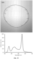
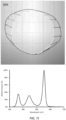
- Figs. 7A-7K provide TM-30-15 Color Vector Graphics (CVGs) [top] and associated Spectral Power Distributions (SPDs) [bottom] for dimming from full output to minimum dim level in increments of 10 percent.
- the CVGs are divided into 16 hue bins, each represented by a point and representing the average of the TM-30-15 hue samples taken in that radial section of the hue graph.
- the vectors represent the difference in hue and saturation of each bin between the test illuminant (dark circle) and a reference illuminator (white circle). Vectors of increasing distance from the center represent an increase in saturation, vectors decreasing distance to the center represent a decrease in saturation.
- each vector tangent to the reference illuminator circle represents a hue shift in that hue bin.
Claims (15)
- Procédé permettant d'augmenter la gamme de couleurs des objets éclairés par un dispositif émetteur de lumière à émetteurs multiples (40) lors de sa gradation, le procédé comprenant :
la commande indépendante de chaque émetteur (1, 2, 3, 4, 5, 6, 7) du dispositif ; et étant caractérisé par l'augmentation du flux lumineux d'au moins un émetteur tout en diminuant simultanément le flux lumineux d'au moins un autre émetteur afin d'augmenter linéairement l'indice de gamut ES TM-30-15 (Rg) à mesure que le flux lumineux total du dispositif émetteur de lumière à émetteurs multiples diminue, de sorte que la gamme de couleurs totale des objets éclairés par le dispositif émetteur de lumière à émetteurs multiples augmente tandis que le flux lumineux total du dispositif émetteur de lumière à émetteurs multiples diminue. - Procédé selon la revendication 1, dans lequel la pluralité d'émetteurs comprend au moins 4 émetteurs LED, éventuellement, où les au moins 4 émetteurs LED comprennent un émetteur rouge, un émetteur vert, un émetteur bleu royal, indigo, et un émetteur blanc.
- Procédé selon la revendication 1 comprenant en outre la diminution linéaire de l'indice de fidélité IES TM-30-15 (Rf) à mesure que le flux lumineux diminue et, éventuellement, la diminution linéaire de l'indice de fidélité IES TM-30-15 (Rf) d'environ 96 à pleine puissance à environ 48 au niveau de gradation minimum.
- Procédé selon la revendication 1 comprenant en outre l'augmentation linéaire de l'indice de gamut IES TM-30-15 (Rg) d'environ 101 à pleine puissance à environ 140 au niveau de gradation minimum.
- Procédé selon la revendication 1 comprenant en outre la diminution linéaire de Duv à mesure que le flux lumineux diminue, éventuellement une diminution linéaire de Duv d'environ 0,0 à pleine puissance à environ -0,03 au niveau de gradation minimum.
- Procédé selon la revendication 1 comprenant en outre l'augmentation linéaire du décalage chromatique IES TM-30-15 dans le premier groupe de teintes (Rcs, h1) à mesure que le flux lumineux diminue, éventuellement l'augmentation linéaire du décalage chromatique IES TM-30-15 dans le premier groupe de teintes (Rcs, h1) d'environ -0,1 % à pleine puissance à environ +35,4 % au niveau de gradation minimum.
- Procédé selon la revendication 1 comprenant en outre :
le maintien d'une température de couleur corrélée constante lorsque le flux lumineux diminue. - Dispositif émetteur de lumière (40) comprenant :au moins 2 émetteurs LED (1, 2, 3, 4, 5, 6, 7) ;au moins un contrôleur interne (30) ;une pluralité de circuits d'attaque (21, 22, 23, 24, 25, 26, 27) configurés pour commander indépendamment les au moins 2 émetteurs LED par l'intermédiaire de l'au moins un contrôleur interne ; et caractérisé en ce qu'ils comprennent :
une logique de programmation configurée pour augmenter le flux lumineux d'au moins un émetteur tout en diminuant simultanément le flux lumineux d'au moins un autre émetteur afin d'augmenter linéairement l'indice de gamut IES TM-30-15 (Rg) à mesure que le flux lumineux total du dispositif émetteur de lumière diminue, de sorte que la gamme de couleurs totale des objets éclairés par le dispositif émetteur de lumière augmente tandis que le flux lumineux total du dispositif émetteur de lumière diminue. - Dispositif émetteur de lumière selon la revendication 8, dans lequel chacun des au moins 2 émetteurs LED est configuré pour émettre une couleur différente.
- Dispositif émetteur de lumière selon la revendication 8, dans lequel les au moins 2 émetteurs LED sont sélectionnés dans le groupe constitué d'un émetteur rouge, d'un émetteur citron vert, d'un émetteur ambre, d'un émetteur vert, d'un émetteur cyan, d'un émetteur bleu, d'un émetteur indigo et d'un émetteur blanc.
- Dispositif émetteur de lumière selon la revendication 8, dans lequel le dispositif émetteur de lumière est en outre configuré pour diminuer linéairement l'indice de fidélité IES TM-30-15 (Rf) à mesure que le flux lumineux diminue, éventuellement, où le dispositif émetteur de lumière est en outre configuré pour diminuer linéairement l'indice de fidélité IFS TM-30-15 (Rf) d'environ 96 à pleine puissance à environ 48 au niveau de gradation minimum.
- Dispositif émetteur de lumière selon la revendication 8, dans lequel le dispositif émetteur de lumière est en outre configuré pour maintenir une température de couleur corrélée constante lorsque le flux lumineux diminue.
- Dispositif émetteur de lumière selon la revendication 8, dans lequel chacun des au moins 2 émetteurs LED comprend une puce LED, ou dans lequel les au moins 2 émetteurs LED sont disposés dans un seul boîtier LED.
- Dispositif émetteur de lumière selon la revendication 8, dans lequel le dispositif émetteur de lumière est un luminaire.
- Dispositif émetteur de lumière selon la revendication 8, comprenant en outre une interface de contrôleur externe connectée de manière communicative à un contrôleur externe et au contrôleur interne.
Applications Claiming Priority (3)
| Application Number | Priority Date | Filing Date | Title |
|---|---|---|---|
| US201762466035P | 2017-03-02 | 2017-03-02 | |
| US201762608590P | 2017-12-21 | 2017-12-21 | |
| PCT/US2018/018297 WO2018160361A1 (fr) | 2017-03-02 | 2018-02-15 | Sources de lumière qui augmentent la chrominance d'un objet lorsqu'elles sont tamisées |
Publications (3)
| Publication Number | Publication Date |
|---|---|
| EP3590313A1 EP3590313A1 (fr) | 2020-01-08 |
| EP3590313A4 EP3590313A4 (fr) | 2020-11-04 |
| EP3590313B1 true EP3590313B1 (fr) | 2023-09-20 |
Family
ID=63370999
Family Applications (1)
| Application Number | Title | Priority Date | Filing Date |
|---|---|---|---|
| EP18760286.7A Active EP3590313B1 (fr) | 2017-03-02 | 2018-02-15 | Sources de lumière qui augmentent la chrominance d'un objet lorsqu'elles sont tamisées |
Country Status (5)
| Country | Link |
|---|---|
| US (3) | US11064583B2 (fr) |
| EP (1) | EP3590313B1 (fr) |
| JP (1) | JP7198212B2 (fr) |
| CN (1) | CN110622622A (fr) |
| WO (1) | WO2018160361A1 (fr) |
Families Citing this family (2)
| Publication number | Priority date | Publication date | Assignee | Title |
|---|---|---|---|---|
| EP3590313B1 (fr) * | 2017-03-02 | 2023-09-20 | The Penn State Research Foundation | Sources de lumière qui augmentent la chrominance d'un objet lorsqu'elles sont tamisées |
| US11382192B2 (en) | 2019-02-08 | 2022-07-05 | Lucidity Lights, Inc. | Preferred lighting spectrum and color shifting circadian lamps |
Family Cites Families (30)
| Publication number | Priority date | Publication date | Assignee | Title |
|---|---|---|---|---|
| US6285140B1 (en) * | 1999-04-21 | 2001-09-04 | Pharos Innovations Inc. | Variable-effect lighting system |
| PT1422975E (pt) * | 2000-04-24 | 2010-07-09 | Philips Solid State Lighting | Produto base de leds |
| US7397485B2 (en) * | 2002-12-16 | 2008-07-08 | Eastman Kodak Company | Color OLED display system having improved performance |
| US8403523B2 (en) | 2003-03-18 | 2013-03-26 | Electronic Theatre Controls, Inc. | Methods, luminaires and systems for matching a composite light spectrum to a target light spectrum |
| TWI263356B (en) * | 2003-11-27 | 2006-10-01 | Kuen-Juei Li | Light-emitting device |
| CN101222797B (zh) * | 2007-01-08 | 2011-06-01 | 香港应用科技研究院有限公司 | 可调节色域之发光二极管背光系统和方法 |
| US8177389B1 (en) * | 2007-09-13 | 2012-05-15 | Cypress Semiconductor Corporation | Deterministically calculating dimming values for four or more light sources |
| CN201185077Y (zh) * | 2008-04-18 | 2009-01-21 | 光远科技股份有限公司 | 具有衰减补偿装置的led背光板液晶显示器 |
| US8096675B1 (en) * | 2008-12-23 | 2012-01-17 | Bridgelux Inc. | Performance and color consistent LED |
| US8223180B2 (en) * | 2009-08-24 | 2012-07-17 | Samsung Electronics Co., Ltd. | Gamut mapping which takes into account pixels in adjacent areas of a display unit |
| US8933644B2 (en) * | 2009-09-18 | 2015-01-13 | Soraa, Inc. | LED lamps with improved quality of light |
| WO2011084837A1 (fr) * | 2010-01-05 | 2011-07-14 | 3M Innovative Properties Company | Contrôle de sources de lumière pour imagerie séquentielle en couleur |
| US8884994B2 (en) * | 2011-05-13 | 2014-11-11 | Samsung Display Co., Ltd. | Method and apparatus for blending display modes |
| US9134178B2 (en) * | 2012-07-27 | 2015-09-15 | Imax Corporation | Observer metameric failure compensation method |
| US10231300B2 (en) * | 2013-01-15 | 2019-03-12 | Cree, Inc. | Systems and methods for controlling solid state lighting during dimming and lighting apparatus incorporating such systems and/or methods |
| EP2966944A4 (fr) | 2013-03-04 | 2016-11-23 | Citizen Electronics | Dispositif électroluminescent, procédé de conception d'un dispositif électroluminescent, procédé d'excitation d'un dispositif électroluminescent, procédé d'éclairage et procédé de fabrication d'un dispositif électroluminescent |
| CN203258507U (zh) * | 2013-03-18 | 2013-10-30 | 深圳市绎立锐光科技开发有限公司 | 一种发光装置及舞台灯系统 |
| US9099028B2 (en) * | 2013-06-28 | 2015-08-04 | Intel Corporation | RGBW dynamic color fidelity control |
| US9410664B2 (en) * | 2013-08-29 | 2016-08-09 | Soraa, Inc. | Circadian friendly LED light source |
| DE112014005132T5 (de) * | 2013-12-06 | 2016-08-11 | Cree, Inc. | Festkörper-Beleuchtungsvorrichtung und Schaltkreise, die LED-Segmente einschliessen, konfiguriert für gezielte spektrale Energieverteilung, und Verfahren zur Bedienung derselben |
| JP6252284B2 (ja) | 2014-03-24 | 2017-12-27 | 東芝ライテック株式会社 | 照明システムおよび照明システムユニット |
| US10161786B2 (en) * | 2014-06-25 | 2018-12-25 | Lutron Ketra, Llc | Emitter module for an LED illumination device |
| CN104599643B (zh) * | 2015-02-13 | 2017-07-14 | 合肥京东方光电科技有限公司 | 可调背光源设备、显示设备及其使用方法 |
| US10683971B2 (en) | 2015-04-30 | 2020-06-16 | Cree, Inc. | Solid state lighting components |
| US10512133B2 (en) * | 2016-01-28 | 2019-12-17 | Ecosense Lighting Inc. | Methods of providing tunable warm white light |
| CN109315037B (zh) * | 2016-01-28 | 2022-07-01 | 生态照明公司 | 用于提供具有高显色性的可调白光的系统 |
| US11729877B2 (en) * | 2017-01-30 | 2023-08-15 | Ideal Industries Lighting Llc | Lighting fixture and methods |
| EP3590313B1 (fr) * | 2017-03-02 | 2023-09-20 | The Penn State Research Foundation | Sources de lumière qui augmentent la chrominance d'un objet lorsqu'elles sont tamisées |
| EP3737469A4 (fr) * | 2018-01-11 | 2021-11-10 | Ecosense Lighting Inc. | Systèmes d'éclairage d'affichage à effets circadiens |
| US10413626B1 (en) * | 2018-03-29 | 2019-09-17 | Vital Vio, Inc. | Multiple light emitter for inactivating microorganisms |
-
2018
- 2018-02-15 EP EP18760286.7A patent/EP3590313B1/fr active Active
- 2018-02-15 WO PCT/US2018/018297 patent/WO2018160361A1/fr unknown
- 2018-02-15 US US16/489,472 patent/US11064583B2/en active Active
- 2018-02-15 CN CN201880028708.4A patent/CN110622622A/zh active Pending
- 2018-02-15 JP JP2019547709A patent/JP7198212B2/ja active Active
-
2021
- 2021-07-12 US US17/373,310 patent/US11638340B2/en active Active
-
2023
- 2023-04-25 US US18/306,898 patent/US20230262856A1/en active Pending
Also Published As
| Publication number | Publication date |
|---|---|
| US11638340B2 (en) | 2023-04-25 |
| US20200383187A1 (en) | 2020-12-03 |
| US20210345461A1 (en) | 2021-11-04 |
| JP7198212B2 (ja) | 2022-12-28 |
| JP2020514999A (ja) | 2020-05-21 |
| EP3590313A4 (fr) | 2020-11-04 |
| US20230262856A1 (en) | 2023-08-17 |
| US11064583B2 (en) | 2021-07-13 |
| WO2018160361A1 (fr) | 2018-09-07 |
| CN110622622A (zh) | 2019-12-27 |
| EP3590313A1 (fr) | 2020-01-08 |
Similar Documents
| Publication | Publication Date | Title |
|---|---|---|
| US20230262856A1 (en) | Light sources that increase object chroma when dimmed | |
| US9445476B2 (en) | System and method for controlling LED segments to provide lighting effects | |
| US11172558B2 (en) | Dim-to-warm LED circuit | |
| CA2909287C (fr) | Appareil d'eclairage a semi-conducteurs dote de caracteristiques de gradateur incandescent | |
| EP2460193B1 (fr) | Dispositifs d'éclairage à semi-conducteurs comprenant des mélanges de lumière | |
| US8988005B2 (en) | Illumination control through selective activation and de-activation of lighting elements | |
| US9756694B2 (en) | Analog circuit for color change dimming | |
| US10264638B2 (en) | Circuits and methods for controlling solid state lighting | |
| EP2481266B1 (fr) | Unité de lampe à pluralité de sources de lumière et procédé de commande à distance de commutateur à bascule pour sélectionner un réglage d'entraînement | |
| US10999907B2 (en) | Selecting parameters in a color-tuning application | |
| US9756696B1 (en) | Configurable LED lighting apparatus | |
| US8502458B2 (en) | Operating device and method for the combined operation of gas discharge lamps and semiconductor light sources | |
| JP2016162753A (ja) | 色変換装置を有する照明装置 |
Legal Events
| Date | Code | Title | Description |
|---|---|---|---|
| STAA | Information on the status of an ep patent application or granted ep patent |
Free format text: STATUS: THE INTERNATIONAL PUBLICATION HAS BEEN MADE |
|
| PUAI | Public reference made under article 153(3) epc to a published international application that has entered the european phase |
Free format text: ORIGINAL CODE: 0009012 |
|
| STAA | Information on the status of an ep patent application or granted ep patent |
Free format text: STATUS: REQUEST FOR EXAMINATION WAS MADE |
|
| 17P | Request for examination filed |
Effective date: 20190924 |
|
| AK | Designated contracting states |
Kind code of ref document: A1 Designated state(s): AL AT BE BG CH CY CZ DE DK EE ES FI FR GB GR HR HU IE IS IT LI LT LU LV MC MK MT NL NO PL PT RO RS SE SI SK SM TR |
|
| AX | Request for extension of the european patent |
Extension state: BA ME |
|
| DAV | Request for validation of the european patent (deleted) | ||
| DAX | Request for extension of the european patent (deleted) | ||
| A4 | Supplementary search report drawn up and despatched |
Effective date: 20201007 |
|
| RIC1 | Information provided on ipc code assigned before grant |
Ipc: H05B 45/20 20200101AFI20201001BHEP Ipc: H01L 27/32 20060101ALI20201001BHEP |
|
| STAA | Information on the status of an ep patent application or granted ep patent |
Free format text: STATUS: EXAMINATION IS IN PROGRESS |
|
| 17Q | First examination report despatched |
Effective date: 20220517 |
|
| REG | Reference to a national code |
Ref document number: 602018057926 Country of ref document: DE Ref country code: DE Ref legal event code: R079 Free format text: PREVIOUS MAIN CLASS: H05B0037020000 Ipc: H01L0027150000 |
|
| RIC1 | Information provided on ipc code assigned before grant |
Ipc: H05B 45/20 20200101ALI20230223BHEP Ipc: H01L 27/15 20060101AFI20230223BHEP |
|
| GRAP | Despatch of communication of intention to grant a patent |
Free format text: ORIGINAL CODE: EPIDOSNIGR1 |
|
| STAA | Information on the status of an ep patent application or granted ep patent |
Free format text: STATUS: GRANT OF PATENT IS INTENDED |
|
| INTG | Intention to grant announced |
Effective date: 20230404 |
|
| P01 | Opt-out of the competence of the unified patent court (upc) registered |
Effective date: 20230601 |
|
| GRAS | Grant fee paid |
Free format text: ORIGINAL CODE: EPIDOSNIGR3 |
|
| GRAA | (expected) grant |
Free format text: ORIGINAL CODE: 0009210 |
|
| STAA | Information on the status of an ep patent application or granted ep patent |
Free format text: STATUS: THE PATENT HAS BEEN GRANTED |
|
| AK | Designated contracting states |
Kind code of ref document: B1 Designated state(s): AL AT BE BG CH CY CZ DE DK EE ES FI FR GB GR HR HU IE IS IT LI LT LU LV MC MK MT NL NO PL PT RO RS SE SI SK SM TR |
|
| REG | Reference to a national code |
Ref country code: GB Ref legal event code: FG4D |
|
| REG | Reference to a national code |
Ref country code: CH Ref legal event code: EP |
|
| REG | Reference to a national code |
Ref country code: DE Ref legal event code: R096 Ref document number: 602018057926 Country of ref document: DE |
|
| REG | Reference to a national code |
Ref country code: IE Ref legal event code: FG4D |
|
| REG | Reference to a national code |
Ref country code: NL Ref legal event code: FP |
|
| REG | Reference to a national code |
Ref country code: LT Ref legal event code: MG9D |
|
| PG25 | Lapsed in a contracting state [announced via postgrant information from national office to epo] |
Ref country code: GR Free format text: LAPSE BECAUSE OF FAILURE TO SUBMIT A TRANSLATION OF THE DESCRIPTION OR TO PAY THE FEE WITHIN THE PRESCRIBED TIME-LIMIT Effective date: 20231221 |
|
| PG25 | Lapsed in a contracting state [announced via postgrant information from national office to epo] |
Ref country code: SE Free format text: LAPSE BECAUSE OF FAILURE TO SUBMIT A TRANSLATION OF THE DESCRIPTION OR TO PAY THE FEE WITHIN THE PRESCRIBED TIME-LIMIT Effective date: 20230920 Ref country code: RS Free format text: LAPSE BECAUSE OF FAILURE TO SUBMIT A TRANSLATION OF THE DESCRIPTION OR TO PAY THE FEE WITHIN THE PRESCRIBED TIME-LIMIT Effective date: 20230920 Ref country code: NO Free format text: LAPSE BECAUSE OF FAILURE TO SUBMIT A TRANSLATION OF THE DESCRIPTION OR TO PAY THE FEE WITHIN THE PRESCRIBED TIME-LIMIT Effective date: 20231220 Ref country code: LV Free format text: LAPSE BECAUSE OF FAILURE TO SUBMIT A TRANSLATION OF THE DESCRIPTION OR TO PAY THE FEE WITHIN THE PRESCRIBED TIME-LIMIT Effective date: 20230920 Ref country code: LT Free format text: LAPSE BECAUSE OF FAILURE TO SUBMIT A TRANSLATION OF THE DESCRIPTION OR TO PAY THE FEE WITHIN THE PRESCRIBED TIME-LIMIT Effective date: 20230920 Ref country code: HR Free format text: LAPSE BECAUSE OF FAILURE TO SUBMIT A TRANSLATION OF THE DESCRIPTION OR TO PAY THE FEE WITHIN THE PRESCRIBED TIME-LIMIT Effective date: 20230920 Ref country code: GR Free format text: LAPSE BECAUSE OF FAILURE TO SUBMIT A TRANSLATION OF THE DESCRIPTION OR TO PAY THE FEE WITHIN THE PRESCRIBED TIME-LIMIT Effective date: 20231221 Ref country code: FI Free format text: LAPSE BECAUSE OF FAILURE TO SUBMIT A TRANSLATION OF THE DESCRIPTION OR TO PAY THE FEE WITHIN THE PRESCRIBED TIME-LIMIT Effective date: 20230920 |
|
| REG | Reference to a national code |
Ref country code: AT Ref legal event code: MK05 Ref document number: 1614098 Country of ref document: AT Kind code of ref document: T Effective date: 20230920 |
|
| PG25 | Lapsed in a contracting state [announced via postgrant information from national office to epo] |
Ref country code: IS Free format text: LAPSE BECAUSE OF FAILURE TO SUBMIT A TRANSLATION OF THE DESCRIPTION OR TO PAY THE FEE WITHIN THE PRESCRIBED TIME-LIMIT Effective date: 20240120 |
|
| PGFP | Annual fee paid to national office [announced via postgrant information from national office to epo] |
Ref country code: NL Payment date: 20240215 Year of fee payment: 7 |
|
| PG25 | Lapsed in a contracting state [announced via postgrant information from national office to epo] |
Ref country code: AT Free format text: LAPSE BECAUSE OF FAILURE TO SUBMIT A TRANSLATION OF THE DESCRIPTION OR TO PAY THE FEE WITHIN THE PRESCRIBED TIME-LIMIT Effective date: 20230920 |
|
| PG25 | Lapsed in a contracting state [announced via postgrant information from national office to epo] |
Ref country code: ES Free format text: LAPSE BECAUSE OF FAILURE TO SUBMIT A TRANSLATION OF THE DESCRIPTION OR TO PAY THE FEE WITHIN THE PRESCRIBED TIME-LIMIT Effective date: 20230920 |
|
| PG25 | Lapsed in a contracting state [announced via postgrant information from national office to epo] |
Ref country code: SM Free format text: LAPSE BECAUSE OF FAILURE TO SUBMIT A TRANSLATION OF THE DESCRIPTION OR TO PAY THE FEE WITHIN THE PRESCRIBED TIME-LIMIT Effective date: 20230920 Ref country code: RO Free format text: LAPSE BECAUSE OF FAILURE TO SUBMIT A TRANSLATION OF THE DESCRIPTION OR TO PAY THE FEE WITHIN THE PRESCRIBED TIME-LIMIT Effective date: 20230920 Ref country code: IS Free format text: LAPSE BECAUSE OF FAILURE TO SUBMIT A TRANSLATION OF THE DESCRIPTION OR TO PAY THE FEE WITHIN THE PRESCRIBED TIME-LIMIT Effective date: 20240120 Ref country code: ES Free format text: LAPSE BECAUSE OF FAILURE TO SUBMIT A TRANSLATION OF THE DESCRIPTION OR TO PAY THE FEE WITHIN THE PRESCRIBED TIME-LIMIT Effective date: 20230920 Ref country code: EE Free format text: LAPSE BECAUSE OF FAILURE TO SUBMIT A TRANSLATION OF THE DESCRIPTION OR TO PAY THE FEE WITHIN THE PRESCRIBED TIME-LIMIT Effective date: 20230920 Ref country code: CZ Free format text: LAPSE BECAUSE OF FAILURE TO SUBMIT A TRANSLATION OF THE DESCRIPTION OR TO PAY THE FEE WITHIN THE PRESCRIBED TIME-LIMIT Effective date: 20230920 Ref country code: AT Free format text: LAPSE BECAUSE OF FAILURE TO SUBMIT A TRANSLATION OF THE DESCRIPTION OR TO PAY THE FEE WITHIN THE PRESCRIBED TIME-LIMIT Effective date: 20230920 Ref country code: PT Free format text: LAPSE BECAUSE OF FAILURE TO SUBMIT A TRANSLATION OF THE DESCRIPTION OR TO PAY THE FEE WITHIN THE PRESCRIBED TIME-LIMIT Effective date: 20240122 Ref country code: SK Free format text: LAPSE BECAUSE OF FAILURE TO SUBMIT A TRANSLATION OF THE DESCRIPTION OR TO PAY THE FEE WITHIN THE PRESCRIBED TIME-LIMIT Effective date: 20230920 |
|
| PGFP | Annual fee paid to national office [announced via postgrant information from national office to epo] |
Ref country code: DE Payment date: 20240206 Year of fee payment: 7 Ref country code: GB Payment date: 20240208 Year of fee payment: 7 |