EP3590267B1 - Minimal touch bracket for cable routing with rack mounted devices - Google Patents
Minimal touch bracket for cable routing with rack mounted devices Download PDFInfo
- Publication number
- EP3590267B1 EP3590267B1 EP18710213.2A EP18710213A EP3590267B1 EP 3590267 B1 EP3590267 B1 EP 3590267B1 EP 18710213 A EP18710213 A EP 18710213A EP 3590267 B1 EP3590267 B1 EP 3590267B1
- Authority
- EP
- European Patent Office
- Prior art keywords
- cable
- cable guide
- guide
- bracket
- moveable
- Prior art date
- Legal status (The legal status is an assumption and is not a legal conclusion. Google has not performed a legal analysis and makes no representation as to the accuracy of the status listed.)
- Active
Links
Images









Classifications
-
- H—ELECTRICITY
- H05—ELECTRIC TECHNIQUES NOT OTHERWISE PROVIDED FOR
- H05K—PRINTED CIRCUITS; CASINGS OR CONSTRUCTIONAL DETAILS OF ELECTRIC APPARATUS; MANUFACTURE OF ASSEMBLAGES OF ELECTRICAL COMPONENTS
- H05K7/00—Constructional details common to different types of electric apparatus
- H05K7/02—Arrangements of circuit components or wiring on supporting structure
-
- H—ELECTRICITY
- H04—ELECTRIC COMMUNICATION TECHNIQUE
- H04Q—SELECTING
- H04Q1/00—Details of selecting apparatus or arrangements
- H04Q1/02—Constructional details
- H04Q1/06—Cable ducts or mountings specially adapted for exchange installations
-
- H—ELECTRICITY
- H02—GENERATION; CONVERSION OR DISTRIBUTION OF ELECTRIC POWER
- H02G—INSTALLATION OF ELECTRIC CABLES OR LINES, OR OF COMBINED OPTICAL AND ELECTRIC CABLES OR LINES
- H02G3/00—Installations of electric cables or lines or protective tubing therefor in or on buildings, equivalent structures or vehicles
- H02G3/02—Details
- H02G3/04—Protective tubing or conduits, e.g. cable ladders or cable troughs
- H02G3/0437—Channels
- H02G3/045—Channels provided with perforations or slots permitting introduction or exit of wires
-
- H—ELECTRICITY
- H04—ELECTRIC COMMUNICATION TECHNIQUE
- H04Q—SELECTING
- H04Q1/00—Details of selecting apparatus or arrangements
- H04Q1/02—Constructional details
- H04Q1/09—Frames or mounting racks not otherwise provided for
Definitions
- the present technology pertains to cable routing and more specifically pertains to a device for routing cables attached to rack mounted devices.
- figure 1 shows a rack mounted router 102 having field replaceable components such as route switch processors 106, interface modules 108, power supply units 110, and a fan tray 104.
- field replaceable components such as route switch processors 106, interface modules 108, power supply units 110, and a fan tray 104.
- replacing the field replaceable units when cables are routed according to traditional best practices requires removing cables or moving cables from the remaining units, which is undesirable.
- US 6,590,785 discloses a cable manager attached to a device, connected to a number of cables.
- the cables are engaged by the cable manager in order to appropriately guide and organize the cables.
- the cable manager is sized and positioned so that when in a normal operating position, certain components remain freely accessible. When so desired, a technician or other user can easily raise and secure the cable manager without disconnecting the cables, thereby moving the coupled cables out of the way of various components of the device.
- the present technology provides minimal touch cable guides for rack mounted devices.
- the minimal touch cable guides disclosed herein provide structures for routing cables from field replaceable units installed in a rack mounted device in such a way that cables of different types are not crossed and provides a mechanism for adjusting installed cabling to permit access to otherwise obscured field replaceable units. Such adjustment of cabling is provided in a controlled manner that does not impair the performance of the installed cabling.
- the present technology includes a cable bend guide arm and a moveable cable guide.
- the moveable cable guide includes a vertical portion, wherein the movable cable guide is configured to guide a cable to the cable bend guide arm.
- the cable bend guide arm is in fixed spatial relationship with respect to the movable cable guide, wherein the cable bend guide arm is configured to move in coordination with movement of the moveable cable guide.
- the moveable cable guide is mounted in a slideable relationship with respect to a rack-mounted device.
- the moveable guide cable is slidably mounted to a mounting frame by a thumbscrew traversing an oblong opening in the mounting frame and terminating in a threaded hole within the moveable cable guide.
- the present technology includes a first cable support arm and a second cable support arm that are pivotally joined together.
- Each of the first cable support arm and the second cable support arm includes a structural portion and a tie down portion, wherein the structural portion gives strength to the first cable support arm and the second cable support arm, and the tie down portion is configured to receive a cable tie down.
- Bracket 300 can be installed in a rack above router 202 that can guide cables 250, 252 up above router 202 and then exit cables 250, 252 from the rack to the left or right of the rack.
- cables 250 can be guided from interface cards 208 on the left of router 202 to space 212 between interface card(s) 208 and route switch processor(s) 206 and guided by vertical portion 305A of moveable cable guide 304A up to the top of router 202 and exit the rack to the left of router 202.
- Channel 212 between interface card(s) 208 and route switch processor(s) 206 is narrow, but wide enough to route cables 250 to the top of router 202 while only minimally blocking access to interface card(s) 208 or route switch processor(s) 206.
- cable(s) 252 can be guided from route switch processor(s) 206 to vertical portion 305B of movable cable guide 304B to the top of router 202, and cable(s) 252 can be guided to exit the rack on the right of router 202.
- FIGS. 3A and 3B show cable bracket 300 in more detail.
- Cable bracket 300 is approximately one rack unit (1RU) tall and can be mounted to the rack directly above router 202. Cables 250, 252 coming from the interface cards/ route switch processors can be routed directly to vertical portions 305A, 305B of movable cable guides 304A, 304B.
- Movable cable guides 304A, 304B are slidably mounted to mounting frame 302.
- Movable cable guides 304A, 304B are in an upside down L configuration, such that the horizontal portions of the movable cable guides 304A, 304B are parallel with the main surface of mounting frame 302 while the vertical portions 305A, 305B of the moveable cable guides are perpendicular to the main surface of mounting platform 302. Vertical portions 305A, 305B of the moveable cable guides 304A, 304B extend below mounting frame 302 and are positioned in front of router 202.
- vertical portion 305A of the left movable cable guide 304A is configured to receive cable(s) 250 coming from the interface card(s) 208 installed on the left side of router 202, and is configured to receive a securing mechanism 313A to secure the cables to vertical portion 305A of movable cable guide 304A.
- Securing mechanism 313A can be Velcro straps, wire, tie downs, or other cord.
- Vertical portion 305A of movable cable guide 304A directs cable(s) 250 up toward mounting frame 302 where the cable(s) 250 is guided around cable bend guide arms 306A, 307A.
- Cable(s) 250 are next routed through cable management bracket(s) 320, which neatly secure the cable(s) 250 as it is directed to the left side of router 202.
- Cable bend guide arms 306A, 307A are positioned with respect to vertical portion 305A of movable cable guide 304A so that a minimum bend radius of cable(s) 250 is preserved.
- Cable bend guide arms 306A, 307A are fixed to guide plate 308A, which is itself fixed to moveable cable guide 304A, thus maintaining a fixed spatial relationship of cable bend guide arms 306A, 307A with respect to moveable cable guide 304A.
- Moveable cable guide 304A is attached to mounting frame 302 by positioning horizontal portion of moveable cable guide 304A under raised lip 312A of mounting frame 302, and also is slidably secured to mounting frame 302 by thumbscrew 310A traversing oblong opening 311A of mounting frame 302 and is ultimately received within a threaded hole within moveable cable guide 304A.
- vertical portion 305B of the right movable cable guide 304B is configured to receive cable(s) 252 coming from the route switch processor(s) 206 installed on the right side of router 202, and is configured to receive a securing mechanism 313B to secure the cable(s) 252 to vertical portion 305B of movable cable guide 304B.
- Securing mechanism 313B can be Velcro straps, wire, tie downs, or other cord.
- Vertical portion 305B of movable cable guide 304B directs cable(s) 252 up toward mounting frame 302 where the cable(s) 252 is guided around cable bend guide arms 306B, 307B.
- Cable bend guide arms 306B, 307B are positioned with respect to vertical portion 305B of movable cable guide 304B so that a minimum bend radius of cable(s) 252 is preserved. Cable bend guide arms 306B, 307B are fixed to guide plate 308B, which is itself fixed to moveable cable guide 304B, thus maintaining a fixed spatial relationship of cable bend guide arms 306B, 307B with respect to moveable cable guide 304B.
- Moveable cable guide 304B is attached to mounting frame 302 by positioning horizontal portion of moveable cable guide 304B under raised lip 312B of mounting frame 302, and also is slidably secured to mounting frame 302 by thumbscrew 310B traversing oblong opening 311B of mounting frame 302 and is ultimately received within a threaded hole within moveable cable guide 304B.
- Cable bracket 300 can be secured by bolts to a rack at left end 315A and right end 315B of cable bracket 300. In some embodiments, cable bracket 300 could be mounted directly to router 202 instead of being mounted to a rack.
- other mechanisms can be used to maintain a fixed or approximately spatial relationship between the cable guide arms and the moveable cable guide.
- gearing, springs, or other mechanisms can be used to ensure that cable bend guide arms move enough to maintain a minimum bend radius of cabling.
- the cable bracket 300 illustrated in figures 2A , 2B , 3A and 3B not only guides cable(s) 250, 252 from interface card(s) 208 of router 202 up and away from router 202, but also facilitates removal and replacement of field replaceable components such as line card(s) 208, route switching processor(s) 206, fan module 204, etc.
- line card(s) 208 route switching processor(s) 206
- fan module 204 etc.
- the area 212 between interface card(s) 208 and route switch processor(s) 206 is relatively narrow. If an interface card 208 needed to be replaced, it would benefit the technician if cabling 205 were moved slightly to the right to permit egress of the old interface card and ingress of the new interface card.
- Cable bracket 300 described herein allows for minimal and controlled movement of cabling 250 to permit egress of the old interface card and ingress of the new interface card without cable(s) 250 interfering with access to interface card(s) 208.
- Figure 7 illustrates a method of replacing a field replaceable unit such as an interface card.
- Movable cable guide 304A is secured to the mounting frame by thumb-tightened screw 310A.
- Thumb-tightened screw 310A can be loosened (602) by hand to permit motion (604) of the movable cable guide with respect to mounting frame 302.
- movable cable guide 304A can be moved slightly to the left to permit access to route switch processor(s) 204.
- Such motion of movable cable guide 304A is minor and controlled so as to not disturb the routing of cable(s) 250 coming out of interface card(s) 208.
- the field replaceable unit can be replaced (606).
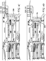
- FIG. 4A Such adjustment of movable cable guide 304A is illustrated in figure 4A .
- vertical portion 305A of movable cable guide 304A is shown positioned in the right most position.
- Thumbscrew 310A is positioned at the far right of oblong opening 311A of mounting frame 302.
- vertical portion 305A of movable cable guide 304A does not obstruct access to interface card(s) 208, but does obstruct access to route switch processor(s) 206.
- Cable 250 remains secured to vertical portion 305A of movable cable guide 304A and remains routed through the cable guide 306A and 307A such that a minimum bend radius of cable 250 is maintained.
- thumbscrew 310A can be loosened (602) and slid (604) to the left of oblong opening 311A, thereby positioning vertical portion 305A of movable cable guide 304A in front of interface card(s) 208 and permitting clear access to route switch processor(s) 206.
- Cable 250 remains secured to vertical portion 305A of movable cable guide 304A and remains routed through cable guide 306A and 307A such that a minimum bend radius of cable 250 is maintained.
- movable cable guide 304A positioned between interface card(s) 208 and route switch processor(s) 206 there is a second movable cable guide 304B positioned between route switch processor(s) 206 and fan module 204.
- Cabling 252 coming out of route switch processor(s) 206 can be secured to vertical portion 305B of second movable cable guide 304B and can be operated in the same fashion as the first movable cable guide 304A as illustrated in figures 4C and 4D .
- cabling 252 can be moved in a controlled fashion slightly to the left to allow access to fan module 204 or can be moved slightly to the right to permit access to the route switch processor(s) 206.
- the field replaceable unit such as a line card, route switch processor, fan module, power module, etc.
- the field replaceable unit can be replaced (606), and movable cable guide 304A can be secured by tightening (608) thumbscrew 310A.
- Figure 4C illustrates vertical portion 305B of movable cable guide 304B positioned in a right-most configuration whereby vertical portion 305B of movable cable guide 304B blocks access to fan module 204.
- Thumbscrew 310 is shown at the right-most portion of oblong opening 311B of mounting frame 302.
- Figure 4D illustrates the vertical portion 305B of movable cable guide 304B positioned in a left most configuration whereby vertical portion 305B of movable cable guide 304B permits access to fan module 204, but obstructs access to route switch processor(s) 206.
- Thumbscrew 310 is shown at the left-most portion of oblong opening 311B of mounting frame 302.
- the field replaceable unit such as a line card, route switch processor, fan module, power module, etc.
- the field replaceable unit can be replaced (606), and movable cable guide 304B can be secured by tightening (608) thumbscrew 310B.
- Figures 5A and 5B illustrate views of another example router 402.
- interface card(s) 405 are stacked in to columns directly adjacent to each other such that there is a column of interface cards on the left and a column of interface cards on the right.
- fan module 404 is to the right of interface card(s) 405.
- Figures 5A and 5B also illustrate an embodiment of a minimal touch bracket 502.
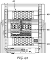
- Figures 6A and 6B illustrate views of another example router 422.
- interface card(s) 425 are stacked in to columns directly adjacent to each other such that there is a column of interface cards on the left and a column of interface cards on the right - just as with router 402 and line cards 405 in Figures 5A and 5B .
- fan modules 424 are above and below interface card(s) 425.
- Figures 6A and 6B also illustrate an embodiment of a minimal touch bracket 502, which is positioned in the same way relative to the line cards 425 as illustrated in figures 5A and 5B .
- Figure 7A is a detail view of one pair of line cards in the arrangement used by the routers in figures 5 and 6 .
- Figure 7A illustrates two interface cards 405A, 405B next to each other - one on the left, and one on the right.
- Figure 7A also illustrates an embodiment of a type of minimal touch cable bracket 502.
- the objectives of the embodiment illustrated in figures 5-8 are similar to the objectives of the embodiment illustrated in figures 1-4 , wherein it is desirable to route cabling to the sides of the router without obscuring other components, avoiding crossing of cables of different types, and allowing for field replaceable components of the router to be replaced without disturbing cabling already in place.
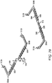
- bracket shown in Figure 7A and 7B has attachment points 512A, 512B - on the left end 512A and right end 512B.
- the left attachment point 512A attaches to the left 408A of the left line card and the right attachment point 512B attaches to the right 408B of the right line card.
- bracket 502 In the middle of bracket 502 is a hinge or pivot 510.
- bracket 502 can be formed of a rigid metal such as iron or steel.
- bracket 502 must be thin enough to be mounted in front of the line cards and to support cabling and still not obscure other line cards above or below. While bracket 502 must be thin it must also be strong enough to support cabling.
- bracket 502 includes structural portion 506.
- Structural portion 506 can be an artery of thickened material, or formed channel (made from stamping or molding).
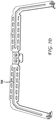
- Figure 7C is a top view of bracket 502 showing structural portion 506 being a raised artery, created by a formed channel on the reverse side (shown in figure 7D , which is a bottom view of bracket 502).
- Bracket 502 also includes a series of tie down portions 508, which can be openings or other attachment mechanisms to allow for tie downs to secure cabling in place.
- cabling coming out of left line card 405A would be directed to left arm 504A of bracket 502, and secured to bracket 502 and run out to the left side of line card 405A.
- cable coming out of right line card 405B would be directed to right arm 504B of the bracket 502 and secured to bracket 502 and run out to the right side of router 402.
- bracket 502 When one of the line cards and needs to be replaced (for example right line card 405B), the right line card cabling would be removed from right arm 504B of bracket 502 and bracket 502 would be unsecured (602) at attachment point 512B which would allow for bracket 502 to pivot (604) at pivot 510 to permit access to right line card 405B.
- bracket 502 can again be secured by securing (608) attachment point 512 on bracket 502 to attachment point 408 to the right of right line card 405B, and cabling can be routed from line card 405B and secured to right arm 504B of bracket 502 and directed out to the right side of router 402.
- Figures 8A and 8B are detail views of one pair of line cards in the arrangement used by the routers in figures 5 and 6 .
- Figure 8A illustrates two interface cards 405A, 405B next to each other - one on the left, and one on the right.
- Figures 8A and 8B also illustrates configurations of an embodiment of a type of minimal touch cable bracket 550.
- Bracket 550 includes three hinges, cable support arm hinge 555A on the left, cable support arm hinge 555B on the right, and decoupable pivot 560 in the middle.
- Decoupable pivot 560 can either operate as a hinge or as a decouplable connection point between left arm 554A and right art 554B.
- bracket 502 can be formed of a rigid metal such as iron or steel. However bracket 502 must be thin enough to be mounted in front of the line cards and to support cabling and still not obscure other line cards above or below. While bracket 502 must be thin it must also be strong enough to support cabling.
- Bracket 550 also includes a series of tie down portions 558, which can be openings or other attachment mechanisms to allow for tie downs to secure cabling in place.
- cabling coming out of left line card 405A would be directed to left arm 554A of bracket 550, and secured to bracket 550 and run out to the left side of line card 405A.
- cable coming out of right line card 405B would be directed to right arm 554B of bracket 550 and secured to bracket 550 and run out to the right side of a router.
- bracket 550 When one of the line cards and needs to be replaced (for example right line card 405B), the right line card, bracket 550 provides at least two options.
- clasp 562 can be removed from decoupable pivot 560, and decoupable pivot 560 can be decoupled (602) to allow free movement of arm 554B.
- arm 554B can be pivoted (604) at cable support arm hinge 555B to the right with the cables still attached to arm 554B, and make room to provide access to line card 405B.
- Line card 405B can then be replaced (606) and decouplable pivot 560 can be rejoined (608) and reinforced with clasp 562.
- bracket 550 can operate similar to that shown for bracket 502 in figure 7A .
- cabling would be removed from right arm 554B of bracket 550 and bracket 550 would be unsecured (602) at attachment point 552B which would allow for bracket 550 to pivot (604) at cable support arm hinge 555A (and pivot at 560 if clasp 562 were removed) to permit access to right line card 405B.
- bracket 550 can again be secured by securing (608) attachment point 552B on bracket 550 to attachment point 408B to the right of right line card 405B, and cabling can be routed from line card 405B and secured to right arm 554B of bracket 550 and directed out to the right side of the router.
- Figure 9 illustrates an example method for using the minimal touch brackets disclosed herein.
- a faster needs to be loosened (602).
- thumb screws 310A or 310B In the brackets illustrated in figures 7A , 7B , 7C , 7D , 8A and 8B , these are securing screws at attachment points 512A 512B, 552A, 552B.
- a moveable component of the minimal touch bracket needs to be moved (604) out to not obstruct a field replaceable unit needing to be replaces.
- brackets illustrated in figures 3A and 3B these are vertical portions 305A or 305B.
- brackets illustrated in figures 7A , 7B , 7C , 7D , 8A and 8B these are arm(s) 506, and 554.
Landscapes
- Engineering & Computer Science (AREA)
- Computer Networks & Wireless Communication (AREA)
- Architecture (AREA)
- Civil Engineering (AREA)
- Structural Engineering (AREA)
- Microelectronics & Electronic Packaging (AREA)
- Insertion, Bundling And Securing Of Wires For Electric Apparatuses (AREA)
- General Engineering & Computer Science (AREA)
- Mechanical Engineering (AREA)
Description
- The present technology pertains to cable routing and more specifically pertains to a device for routing cables attached to rack mounted devices.
- Traditional cable management mechanisms for rack-mounted devices have become insufficient as rack-mounted devices have been developed that have more ports, and that have a combination of fiber data cables, copper data cables, and copper power cables connected to the same device. Conventional wisdom is that fiber cables and copper cables should remain separated, which complicates cable routing. Additionally, it is considered best practice to not touch or disturb fiber cables that are already installed. Furthermore, its also considered best practice to not bend some cables beyond a specified bend radius
- To accommodate the above mentioned principles and best practices, current cable routing techniques often exit cables in such a way that cable routing can interfere with access to field replaceable components within a given device. For example,
figure 1 shows a rack mountedrouter 102 having field replaceable components such asroute switch processors 106,interface modules 108,power supply units 110, and afan tray 104. However replacing the field replaceable units when cables are routed according to traditional best practices requires removing cables or moving cables from the remaining units, which is undesirable. -
US 6,590,785 discloses a cable manager attached to a device, connected to a number of cables. The cables are engaged by the cable manager in order to appropriately guide and organize the cables. The cable manager is sized and positioned so that when in a normal operating position, certain components remain freely accessible. When so desired, a technician or other user can easily raise and secure the cable manager without disconnecting the cables, thereby moving the coupled cables out of the way of various components of the device. - In order to describe the manner in which the above recited and other advantages and features of the disclosure can be obtained, a more particular description of the principles briefly described above will be rendered by references to specific embodiments thereof, which are illustrated, in the appended drawings. Understanding that these drawings depict only exemplary embodiments of the disclosure and are not therefore to be considered to be limiting of its scope, the principles herein are described and explained with additional specificity and detail through the use of the accompanying drawings in which:
-
Figure 1 illustrates an example router with cables routed in a conventional fashion and interfering with fan tray access and with mixed cable types; -
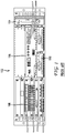
Figure 2A is a plan view and illustrates a view of an example router with an embodiment of a minimal touch cable bracket; -
Figure 2B is a perspective view and illustrates a view of an example router with an embodiment of a minimal touch cable bracket; -
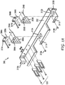
Figure 3A illustrates an exploded view of an embodiment of a minimal touch cable bracket; -
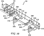
Figure 3B illustrates an example of an embodiment of a minimal touch cable bracket; -
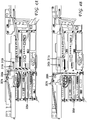
Figures 4A, 4B ,4C, and 4D illustrate example configurations of an embodiment of a minimal touch cable bracket installed above a router; -
Figures 5A and5B illustrate an example views of a router with embodiment of a minimal touch cable bracket; -
Figures 6A and6B illustrate an example views of a router with embodiment of a minimal touch cable bracket; -
Figure 7A illustrates an example view of a line card with an embodiment of a minimal touch cable bracket; -
Figure 7B illustrates an example view of an embodiment of a minimal touch cable bracket; -
Figure 7C illustrates an example top view of an embodiment of a minimal touch cable bracket; -
Figure 7D illustrates an example bottom view of an embodiment of a minimal touch cable bracket; -
Figure 8A illustrates an example view of a line card with an embodiment of a minimal touch cable bracket; -
Figure 8B illustrates an example view of a line card with an embodiment of a minimal touch cable bracket; -
Figure 8C illustrates an example view of a line card with an embodiment of a minimal touch cable bracket; and -
Figure 9 illustrates an example method of replacing a field replaceable unit. - Various embodiments of the disclosure are discussed in detail below. While specific implementations are discussed, it should be understood that this is done for illustration purposes only. A person skilled in the relevant art will recognize that other components and configurations may be used without parting from the scope of the disclosure.
- Aspects of the invention are set out in the independent claims and preferred features are set out in the dependent claims. Features of one aspect may be applied to each aspect alone or in combination with other aspects.
- The present technology provides minimal touch cable guides for rack mounted devices. The minimal touch cable guides disclosed herein provide structures for routing cables from field replaceable units installed in a rack mounted device in such a way that cables of different types are not crossed and provides a mechanism for adjusting installed cabling to permit access to otherwise obscured field replaceable units. Such adjustment of cabling is provided in a controlled manner that does not impair the performance of the installed cabling.
- In one embodiment the present technology includes a cable bend guide arm and a moveable cable guide. The moveable cable guide includes a vertical portion, wherein the movable cable guide is configured to guide a cable to the cable bend guide arm. The cable bend guide arm is in fixed spatial relationship with respect to the movable cable guide, wherein the cable bend guide arm is configured to move in coordination with movement of the moveable cable guide. Furthermore, the moveable cable guide is mounted in a slideable relationship with respect to a rack-mounted device. The moveable guide cable is slidably mounted to a mounting frame by a thumbscrew traversing an oblong opening in the mounting frame and terminating in a threaded hole within the moveable cable guide.
- In another embodiment the present technology includes a first cable support arm and a second cable support arm that are pivotally joined together. Each of the first cable support arm and the second cable support arm includes a structural portion and a tie down portion, wherein the structural portion gives strength to the first cable support arm and the second cable support arm, and the tie down portion is configured to receive a cable tie down.
-
Figures 2A and2B illustrate one solution to the problems mentioned above. Bracket 300 can be installed in a rack aboverouter 202 that can guidecables router 202 and thenexit cables - As shown in
FIGURE 2A cables 250 can be guided frominterface cards 208 on the left ofrouter 202 tospace 212 between interface card(s) 208 and route switch processor(s) 206 and guided byvertical portion 305A ofmoveable cable guide 304A up to the top ofrouter 202 and exit the rack to the left ofrouter 202. Channel 212 between interface card(s) 208 and route switch processor(s) 206 is narrow, but wide enough toroute cables 250 to the top ofrouter 202 while only minimally blocking access to interface card(s) 208 or route switch processor(s) 206. - Similarly, cable(s) 252 can be guided from route switch processor(s) 206 to
vertical portion 305B ofmovable cable guide 304B to the top ofrouter 202, and cable(s) 252 can be guided to exit the rack on the right ofrouter 202. -
Figures 3A and3B showcable bracket 300 in more detail.Cable bracket 300 is approximately one rack unit (1RU) tall and can be mounted to the rack directly aboverouter 202.Cables vertical portions movable cable guides Movable cable guides frame 302.Movable cable guides movable cable guides mounting frame 302 while thevertical portions mounting platform 302.Vertical portions moveable cable guides mounting frame 302 and are positioned in front ofrouter 202. - On the left side of
router 202vertical portion 305A of the leftmovable cable guide 304A is configured to receive cable(s) 250 coming from the interface card(s) 208 installed on the left side ofrouter 202, and is configured to receive asecuring mechanism 313A to secure the cables tovertical portion 305A ofmovable cable guide 304A. Securingmechanism 313A can be Velcro straps, wire, tie downs, or other cord.Vertical portion 305A ofmovable cable guide 304A directs cable(s) 250 up toward mountingframe 302 where the cable(s) 250 is guided around cablebend guide arms router 202. Cable bend guidearms vertical portion 305A ofmovable cable guide 304A so that a minimum bend radius of cable(s) 250 is preserved. Cable bend guidearms plate 308A, which is itself fixed tomoveable cable guide 304A, thus maintaining a fixed spatial relationship of cable bend guidearms moveable cable guide 304A.Moveable cable guide 304A is attached to mountingframe 302 by positioning horizontal portion ofmoveable cable guide 304A under raisedlip 312A of mountingframe 302, and also is slidably secured to mountingframe 302 bythumbscrew 310A traversingoblong opening 311A of mountingframe 302 and is ultimately received within a threaded hole withinmoveable cable guide 304A. - On the right side of
router 202vertical portion 305B of the rightmovable cable guide 304B is configured to receive cable(s) 252 coming from the route switch processor(s) 206 installed on the right side ofrouter 202, and is configured to receive asecuring mechanism 313B to secure the cable(s) 252 tovertical portion 305B ofmovable cable guide 304B. Securingmechanism 313B can be Velcro straps, wire, tie downs, or other cord.Vertical portion 305B ofmovable cable guide 304B directs cable(s) 252 up toward mountingframe 302 where the cable(s) 252 is guided around cable bend guidearms arms vertical portion 305B ofmovable cable guide 304B so that a minimum bend radius of cable(s) 252 is preserved. Cable bend guidearms plate 308B, which is itself fixed tomoveable cable guide 304B, thus maintaining a fixed spatial relationship of cable bend guidearms moveable cable guide 304B.Moveable cable guide 304B is attached to mountingframe 302 by positioning horizontal portion ofmoveable cable guide 304B under raisedlip 312B of mountingframe 302, and also is slidably secured to mountingframe 302 bythumbscrew 310B traversingoblong opening 311B of mountingframe 302 and is ultimately received within a threaded hole withinmoveable cable guide 304B. -
Cable bracket 300 can be secured by bolts to a rack atleft end 315A andright end 315B ofcable bracket 300. In some embodiments,cable bracket 300 could be mounted directly torouter 202 instead of being mounted to a rack. - In some embodiments, while the various figures illustrate cable bend guide
arms plate moveable cable guide - The
cable bracket 300 illustrated infigures 2A ,2B ,3A and3B not only guides cable(s) 250, 252 from interface card(s) 208 ofrouter 202 up and away fromrouter 202, but also facilitates removal and replacement of field replaceable components such as line card(s) 208, route switching processor(s) 206,fan module 204, etc. Referring back tofigure 2A where cabling 250 can be seen being routed up between interface card(s) 208 and route switch processor(s) 206, it will be appreciated that thearea 212 between interface card(s) 208 and route switch processor(s) 206 is relatively narrow. If aninterface card 208 needed to be replaced, it would benefit the technician if cabling 205 were moved slightly to the right to permit egress of the old interface card and ingress of the new interface card. -
Cable bracket 300 described herein allows for minimal and controlled movement of cabling 250 to permit egress of the old interface card and ingress of the new interface card without cable(s) 250 interfering with access to interface card(s) 208.Figure 7 illustrates a method of replacing a field replaceable unit such as an interface card.Movable cable guide 304A is secured to the mounting frame by thumb-tightenedscrew 310A. Thumb-tightenedscrew 310A can be loosened (602) by hand to permit motion (604) of the movable cable guide with respect to mountingframe 302. Since the cable(s) 250 is attached tovertical portion 305A ofmovable cable guide 304A whenmovable cable guide 304A is slid slightly (604) to the right cable(s) 250 will move with movable cable guide 340A, thus permitting access to the interface card(s) 208. Likewise should route switch processor(s) 206 need to be replacedmovable cable guide 304A can be moved slightly to the left to permit access to route switch processor(s) 204. Such motion ofmovable cable guide 304A is minor and controlled so as to not disturb the routing of cable(s) 250 coming out of interface card(s) 208. With clear access to the field replaceable unit such as a line card, route switch processor, fan module, power module, etc, the field replaceable unit can be replaced (606). - Such adjustment of
movable cable guide 304A is illustrated infigure 4A . Infigure 4A vertical portion 305A ofmovable cable guide 304A is shown positioned in the right most position.Thumbscrew 310A is positioned at the far right ofoblong opening 311A of mountingframe 302. In this configurationvertical portion 305A ofmovable cable guide 304A does not obstruct access to interface card(s) 208, but does obstruct access to route switch processor(s) 206.Cable 250 remains secured tovertical portion 305A ofmovable cable guide 304A and remains routed through thecable guide cable 250 is maintained. - When access to
route switch processors 206 is needed,thumbscrew 310A can be loosened (602) and slid (604) to the left ofoblong opening 311A, thereby positioningvertical portion 305A ofmovable cable guide 304A in front of interface card(s) 208 and permitting clear access to route switch processor(s) 206.Cable 250 remains secured tovertical portion 305A ofmovable cable guide 304A and remains routed throughcable guide cable 250 is maintained. - In addition to
movable cable guide 304A positioned between interface card(s) 208 and route switch processor(s) 206 there is a secondmovable cable guide 304B positioned between route switch processor(s) 206 andfan module 204. Cabling 252 coming out of route switch processor(s) 206 can be secured tovertical portion 305B of secondmovable cable guide 304B and can be operated in the same fashion as the firstmovable cable guide 304A as illustrated infigures 4C and 4D . Using the secondmovable cable guide 304B cabling 252 can be moved in a controlled fashion slightly to the left to allow access tofan module 204 or can be moved slightly to the right to permit access to the route switch processor(s) 206. With clear access to the field replaceable unit such as a line card, route switch processor, fan module, power module, etc., the field replaceable unit can be replaced (606), andmovable cable guide 304A can be secured by tightening (608)thumbscrew 310A. -
Figure 4C illustratesvertical portion 305B ofmovable cable guide 304B positioned in a right-most configuration wherebyvertical portion 305B ofmovable cable guide 304B blocks access tofan module 204. Thumbscrew 310 is shown at the right-most portion ofoblong opening 311B of mountingframe 302.Figure 4D illustrates thevertical portion 305B ofmovable cable guide 304B positioned in a left most configuration wherebyvertical portion 305B ofmovable cable guide 304B permits access tofan module 204, but obstructs access to route switch processor(s) 206. Thumbscrew 310 is shown at the left-most portion ofoblong opening 311B of mountingframe 302. With clear access to the field replaceable unit such as a line card, route switch processor, fan module, power module, etc., the field replaceable unit can be replaced (606), andmovable cable guide 304B can be secured by tightening (608)thumbscrew 310B. -
Figures 5A and5B illustrate views of anotherexample router 402. Inrouter 402 interface card(s) 405 are stacked in to columns directly adjacent to each other such that there is a column of interface cards on the left and a column of interface cards on the right. In this routerconfiguration fan module 404 is to the right of interface card(s) 405. Unlike the router illustrated infigures 2A-2B , there is not enough room in between field replaceable units located adjacent to each other (left column and right column of line cards) to route cable.Figures 5A and5B also illustrate an embodiment of aminimal touch bracket 502. -
Figures 6A and6B illustrate views of anotherexample router 422. Inrouter 422 interface card(s) 425 are stacked in to columns directly adjacent to each other such that there is a column of interface cards on the left and a column of interface cards on the right - just as withrouter 402 andline cards 405 inFigures 5A and5B . In this routerconfiguration fan modules 424 are above and below interface card(s) 425. Just as withrouter 402, there is not enough room in between field replaceable units located adjacent to each other (left column and right column of line cards 425) to route cable.Figures 6A and6B also illustrate an embodiment of aminimal touch bracket 502, which is positioned in the same way relative to theline cards 425 as illustrated infigures 5A and5B . -
Figure 7A is a detail view of one pair of line cards in the arrangement used by the routers infigures 5 and6 .Figure 7A illustrates twointerface cards Figure 7A also illustrates an embodiment of a type of minimaltouch cable bracket 502. - The objectives of the embodiment illustrated in
figures 5-8 are similar to the objectives of the embodiment illustrated infigures 1-4 , wherein it is desirable to route cabling to the sides of the router without obscuring other components, avoiding crossing of cables of different types, and allowing for field replaceable components of the router to be replaced without disturbing cabling already in place. - The bracket shown in
Figure 7A and7B has attachment points 512A, 512B - on theleft end 512A andright end 512B. Theleft attachment point 512A attaches to the left 408A of the left line card and theright attachment point 512B attaches to the right 408B of the right line card. In the middle ofbracket 502 is a hinge orpivot 510. In someembodiments bracket 502 can be formed of a rigid metal such as iron or steel. Howeverbracket 502 must be thin enough to be mounted in front of the line cards and to support cabling and still not obscure other line cards above or below. Whilebracket 502 must be thin it must also be strong enough to support cabling. - As illustrated in
figures 7C and7D , to provide additional structure,bracket 502 includesstructural portion 506.Structural portion 506 can be an artery of thickened material, or formed channel (made from stamping or molding).Figure 7C is a top view ofbracket 502 showingstructural portion 506 being a raised artery, created by a formed channel on the reverse side (shown infigure 7D , which is a bottom view of bracket 502). -
Bracket 502 also includes a series of tie downportions 508, which can be openings or other attachment mechanisms to allow for tie downs to secure cabling in place. - In operation, cabling coming out of
left line card 405A would be directed toleft arm 504A ofbracket 502, and secured tobracket 502 and run out to the left side ofline card 405A. Likewise cable coming out ofright line card 405B would be directed toright arm 504B of thebracket 502 and secured tobracket 502 and run out to the right side ofrouter 402. - When one of the line cards and needs to be replaced (for example
right line card 405B), the right line card cabling would be removed fromright arm 504B ofbracket 502 andbracket 502 would be unsecured (602) atattachment point 512B which would allow forbracket 502 to pivot (604) atpivot 510 to permit access toright line card 405B. Whenright line card 405B is replaced (606)bracket 502 can again be secured by securing (608) attachment point 512 onbracket 502 to attachment point 408 to the right ofright line card 405B, and cabling can be routed fromline card 405B and secured toright arm 504B ofbracket 502 and directed out to the right side ofrouter 402. -
Figures 8A and8B are detail views of one pair of line cards in the arrangement used by the routers infigures 5 and6 .Figure 8A illustrates twointerface cards Figures 8A and8B also illustrates configurations of an embodiment of a type of minimaltouch cable bracket 550. - The bracket shown in
figures 8A and8B has attachment points 552A, 552B - on theleft end 552A andright end 552B. Theleft attachment point 552A attaches to the left 408A of the left line card and theright attachment point 552B attaches to the right 408B of the right line card. The main different between bracket 504 andbracket 550 is in the arrangement of hinge(s).Bracket 550 includes three hinges, cablesupport arm hinge 555A on the left, cablesupport arm hinge 555B on the right, anddecoupable pivot 560 in the middle.Decoupable pivot 560 can either operate as a hinge or as a decouplable connection point betweenleft arm 554A andright art 554B. Whenarms decoupable pivot 560 is not flexed,clasp 562 can be removably installed to provide additional structure. - In some
embodiments bracket 502 can be formed of a rigid metal such as iron or steel. Howeverbracket 502 must be thin enough to be mounted in front of the line cards and to support cabling and still not obscure other line cards above or below. Whilebracket 502 must be thin it must also be strong enough to support cabling. -
Bracket 550 also includes a series of tie downportions 558, which can be openings or other attachment mechanisms to allow for tie downs to secure cabling in place. - In operation, cabling coming out of
left line card 405A would be directed toleft arm 554A ofbracket 550, and secured tobracket 550 and run out to the left side ofline card 405A. Likewise cable coming out ofright line card 405B would be directed toright arm 554B ofbracket 550 and secured tobracket 550 and run out to the right side of a router. - When one of the line cards and needs to be replaced (for example
right line card 405B), the right line card,bracket 550 provides at least two options. In one option, illustrated inFigure 8C ,clasp 562 can be removed fromdecoupable pivot 560, anddecoupable pivot 560 can be decoupled (602) to allow free movement ofarm 554B. In this option of operation, it may not be necessary to remove cabling fromarm 554B. Instead arm 554B can be pivoted (604) at cablesupport arm hinge 555B to the right with the cables still attached toarm 554B, and make room to provide access toline card 405B.Line card 405B can then be replaced (606) anddecouplable pivot 560 can be rejoined (608) and reinforced withclasp 562. - In another option,
bracket 550 can operate similar to that shown forbracket 502 infigure 7A . Using this option cabling would be removed fromright arm 554B ofbracket 550 andbracket 550 would be unsecured (602) atattachment point 552B which would allow forbracket 550 to pivot (604) at cable support arm hinge 555A (and pivot at 560 ifclasp 562 were removed) to permit access toright line card 405B. Whenright line card 405B is replaced (606)bracket 550 can again be secured by securing (608)attachment point 552B onbracket 550 toattachment point 408B to the right ofright line card 405B, and cabling can be routed fromline card 405B and secured toright arm 554B ofbracket 550 and directed out to the right side of the router. -
Figure 9 illustrates an example method for using the minimal touch brackets disclosed herein. First, a faster needs to be loosened (602). In the brackets illustrated infigures 3A and3B , these arethumb screws figures 7A ,7B ,7C ,7D ,8A and8B , these are securing screws at attachment points512A - Next, a moveable component of the minimal touch bracket needs to be moved (604) out to not obstruct a field replaceable unit needing to be replaces. In the brackets illustrated in
figures 3A and3B , these arevertical portions figures 7A ,7B ,7C ,7D ,8A and8B , these are arm(s) 506, and 554. - Next, field replaceable units are replaced (606), and the bracket can be restored to its installed configuration and the moveable component fasteners can be tightened (608).
- Although a variety of examples and other information was used to explain aspects within the scope of the appended claims, no limitation of the claims should be implied based on particular features or arrangements in such examples, as one of ordinary skill would be able to use these examples to derive a wide variety of implementations. Further and although some subject matter may have been described in language specific to examples of structural features and/or method steps, it is to be understood that the subject matter defined in the appended claims is not necessarily limited to these described features or acts. For example, such functionality can be distributed differently or performed in components other than those identified herein. Rather, the described features and steps are disclosed as examples of components of systems and methods within the scope of the appended claims.
Claims (11)
- A cable guide bracket (300) comprising:a cable bend guide arm (306A, 307A, 306B, 307B); anda moveable cable guide (304A, 304B) formed by a vertical portion (305A, 305B) and a horizontal portion, wherein the vertical portion is configured to have a cable secured thereto by a cable securing mechanism (313A, 313B); anda mounting frame (302), wherein the horizontal portion of the moveable cable guide (304A, 304B) is configured to be movable secured to an interior portion of the mounting frame (302), and the vertical portion of the cable is guided, when the cable guide bracket (300) is in use, from the movable cable guide (304A, 304B) to the cable bend guide arm (306A, 307A, 306B, 307B), where the cable is guided around the cable bend guide arm (306A, 307A, 306B, 307B), wherein the moveable cable guide (304A, 304B) and the cable bend guide arm (306A, 307A, 306B, 307B) are positioned in fixed spatial relationship, such that the cable bend guide arm (306A, 307A, 306B, 307B) is configured to move in coordination with movement of the moveable cable guide, whereby a minimum bend radius of the cable is preserved when the movable cable guide (304A, 304B) is moved from a first position to a second position with respect to the mounting frame (302).
- The cable guide bracket of claim 1, wherein the cable bend guide arm is fixed to the moveable cable guide.
- The cable guide bracket of any of claims 1 to 2, wherein the moveable cable guide is mounted in a slideable relationship with respect to a rack mounted device.
- The cable guide bracket of any of claims 1 to 3 comprising:the mounting frame,wherein the moveable cable guide is slidably mounted to the mounting frame by a thumbscrew traversing an oblong opening in the mounting frame and terminating in a threaded hole within the moveable cable guide.
- The cable guide bracket of claim 4, comprising:
a cable securement bracket connected to the mounting frame. - The cable guide bracket of claim 4 or 5, wherein the moveable cable guide is "L" shaped defined by the horizontal portion and the vertical portion, the horizontal portion including the threaded hole.
- The cable guide bracket of any of claims 4 to 6, wherein the mounting frame is configured to be mounted to a rack above a rack mounted device, which benefits from cable management by the cable guide bracket.
- A method of replacing a rack mounted device mounted in a rack having mounted therein a cable guide bracket (300) according to any preceding claim, the method comprising:moving the movable cable guide (304A, 304B) from the first position to the second position; andreplacing the rack mounted device.
- The method of claim 8, wherein the movable cable guide guides the cable from at least one rack mounted device that is not being replaced, the cable remaining attached to the movable cable guide during the moving.
- The method of claim 8 or 9, comprising:
prior to moving the moveable cable guide, loosing a thumb -tightened screw to permit movement of the moveable cable guide. - The method of claim 9, comprising:
after moving the moveable cable guide into the second position, tightening the thumb-tightened screw to prevent movement of the moveable cable guide.
Applications Claiming Priority (3)
| Application Number | Priority Date | Filing Date | Title |
|---|---|---|---|
| US201762465879P | 2017-03-02 | 2017-03-02 | |
| US15/487,148 US10820440B2 (en) | 2017-03-02 | 2017-04-13 | Minimal touch bracket for cable routing with rack mounted devices |
| PCT/US2018/019361 WO2018160447A1 (en) | 2017-03-02 | 2018-02-23 | Minimal touch bracket for cable routing with rack mounted devices |
Publications (2)
| Publication Number | Publication Date |
|---|---|
| EP3590267A1 EP3590267A1 (en) | 2020-01-08 |
| EP3590267B1 true EP3590267B1 (en) | 2021-09-15 |
Family
ID=63355572
Family Applications (1)
| Application Number | Title | Priority Date | Filing Date |
|---|---|---|---|
| EP18710213.2A Active EP3590267B1 (en) | 2017-03-02 | 2018-02-23 | Minimal touch bracket for cable routing with rack mounted devices |
Country Status (4)
| Country | Link |
|---|---|
| US (1) | US10820440B2 (en) |
| EP (1) | EP3590267B1 (en) |
| CN (1) | CN110419227B (en) |
| WO (1) | WO2018160447A1 (en) |
Families Citing this family (5)
| Publication number | Priority date | Publication date | Assignee | Title |
|---|---|---|---|---|
| US11184688B2 (en) * | 2019-11-04 | 2021-11-23 | Cisco Technology, Inc. | Minimal touch post for multi-layer cable routing |
| US11251593B2 (en) * | 2019-11-04 | 2022-02-15 | Cisco Technology, Inc. | Minimal touch post for multi-layer cable routing |
| CN111031410B (en) * | 2019-12-16 | 2024-03-22 | 浙江建设职业技术学院 | Switch cascade mounting rack for organization management system and use method thereof |
| CN113300275B (en) * | 2021-07-15 | 2022-05-27 | 国家电网有限公司 | Cable laying device convenient to blowing |
| US20250125598A1 (en) * | 2023-10-17 | 2025-04-17 | Vertiv Corporation | Cable carrier for a power system |
Family Cites Families (33)
| Publication number | Priority date | Publication date | Assignee | Title |
|---|---|---|---|---|
| CA1015816A (en) * | 1975-06-24 | 1977-08-16 | Canadian Chromalox Company | Electrical apparatus housing structure having a terminal box section with removable cover plate and cable clamp |
| CA1163296A (en) * | 1980-10-10 | 1984-03-06 | L. Ronald Ofield | Optional rear entry back connector for a baseboard heater |
| US5921402A (en) * | 1998-04-27 | 1999-07-13 | Systems Manufacturing Corporation | Cable management track system |
| US6215069B1 (en) * | 1999-04-06 | 2001-04-10 | Hubbell Incorporated | Cable management panel assembly |
| WO2001001534A1 (en) * | 1999-06-28 | 2001-01-04 | Cooper B-Line Limited | Cable guiding |
| US6586680B1 (en) * | 2000-06-02 | 2003-07-01 | Panduit Corp. | Modular bend radius control fixture |
| US6501899B1 (en) * | 2000-06-02 | 2002-12-31 | Panduit Corp. | Vertical cable management system |
| US6398149B1 (en) * | 2001-01-16 | 2002-06-04 | Ortronics, Inc. | Cable management system with adjustable cable spools |
| US6590785B1 (en) * | 2001-08-27 | 2003-07-08 | David Lima | Cable management |
| US7083051B2 (en) * | 2002-11-15 | 2006-08-01 | Adc Telecommunications, Inc. | Cable management assembly, system and method |
| US7022916B1 (en) * | 2003-05-21 | 2006-04-04 | Emc Corporation | Techniques for controlling movement of a set of cables |
| TWM252187U (en) * | 2003-11-13 | 2004-12-01 | John Peng | Wire arrangement rack |
| US7027706B2 (en) | 2003-12-23 | 2006-04-11 | Hewlett-Packard Development Company, L.P. | Systems, apparatuses, and methods for managing cables with minimum bend radius |
| JP2005189332A (en) * | 2003-12-24 | 2005-07-14 | Three M Innovative Properties Co | Optical connector, optical fiber with connector, optical fiber connecting apparatus and method for connecting optical fiber |
| US7489849B2 (en) * | 2004-11-03 | 2009-02-10 | Adc Telecommunications, Inc. | Fiber drop terminal |
| US7431610B2 (en) * | 2005-01-21 | 2008-10-07 | Leviton Manufacturing Co., Inc. | Cable slack manager system and method |
| JP4493559B2 (en) * | 2005-07-08 | 2010-06-30 | 株式会社椿本チエイン | Skate unit for cable protection guide device |
| US7302153B2 (en) | 2005-10-26 | 2007-11-27 | Telect Inc. | Fiber management access system |
| JP4799240B2 (en) * | 2006-03-29 | 2011-10-26 | 株式会社椿本チエイン | Skate unit for cable protection guide device |
| RU2451957C2 (en) * | 2006-09-13 | 2012-05-27 | 3М Инновейтив Пропертиз Компани | System for maintenance of fire-optic circuits with splice tray |
| US7753319B1 (en) * | 2007-12-10 | 2010-07-13 | The United States Of America As Represented By The Secretary Of The Navy | Adjustable cable hanger for securing cables externally |
| CA2711669A1 (en) * | 2008-01-07 | 2009-07-16 | Chatsworth Products, Inc. | Cable management accessories |
| US8003890B2 (en) * | 2008-01-07 | 2011-08-23 | Chatsworth Products, Inc. | Repositionable shelf-mounted handle spool assembly for cable routing |
| JP5414704B2 (en) * | 2011-01-21 | 2014-02-12 | 株式会社椿本チエイン | Articulated cable protection guide device |
| WO2012136702A1 (en) * | 2011-04-06 | 2012-10-11 | Fci | Cable guide boot assembly |
| US9556972B2 (en) * | 2011-07-15 | 2017-01-31 | Commscope Technologies Llc | Adjustable cable manager |
| TWI446860B (en) * | 2011-10-28 | 2014-07-21 | Hon Hai Prec Ind Co Ltd | Cables tidying device |
| US9144174B2 (en) * | 2012-12-07 | 2015-09-22 | King Slide Works Co., Ltd. | Cable management arm assembly |
| JP6101862B2 (en) * | 2013-04-29 | 2017-03-22 | フィニサー コーポレイション | Cable clips and cable management structures for use with optoelectric modules |
| JP6074711B2 (en) * | 2013-09-10 | 2017-02-08 | パナソニックIpマネジメント株式会社 | Cable holding member, electrical connection device, connector device |
| ES2707730T3 (en) * | 2013-09-13 | 2019-04-04 | Te Connectivity Corp | Adjustable cable managers |
| JP6317291B2 (en) * | 2015-04-27 | 2018-04-25 | 株式会社椿本チエイン | Cable protection guide device and fixing member |
| US9966695B2 (en) * | 2015-05-11 | 2018-05-08 | Rockwell Automation Technologies, Inc. | Cable clamping system for strain relief and grounding |
-
2017
- 2017-04-13 US US15/487,148 patent/US10820440B2/en active Active
-
2018
- 2018-02-23 WO PCT/US2018/019361 patent/WO2018160447A1/en not_active Ceased
- 2018-02-23 CN CN201880015239.2A patent/CN110419227B/en active Active
- 2018-02-23 EP EP18710213.2A patent/EP3590267B1/en active Active
Also Published As
| Publication number | Publication date |
|---|---|
| US10820440B2 (en) | 2020-10-27 |
| CN110419227B (en) | 2022-03-29 |
| CN110419227A (en) | 2019-11-05 |
| WO2018160447A1 (en) | 2018-09-07 |
| US20180252335A1 (en) | 2018-09-06 |
| EP3590267A1 (en) | 2020-01-08 |
Similar Documents
| Publication | Publication Date | Title |
|---|---|---|
| WO2018160447A1 (en) | Minimal touch bracket for cable routing with rack mounted devices | |
| EP3262908B1 (en) | Front rack cable management system and apparatus | |
| CA2714909C (en) | Wall-mounted attaching apparatus | |
| US12010809B2 (en) | Adjustable cable management bracket for modular electronic system | |
| US10028417B2 (en) | Modular network switches, associated structures, and associated methods of manufacture and use | |
| US5921402A (en) | Cable management track system | |
| EP3300195B1 (en) | Rail wiring duct | |
| US6788542B2 (en) | Hinged cover for rack-mountable module | |
| US20090046429A1 (en) | Deformable duct guides that accommodate electronic connection lines | |
| EP3657919B1 (en) | Cable management assembly | |
| US20090225509A1 (en) | Bag computer two part display panel | |
| US8605416B2 (en) | Bag computer two part display panel | |
| WO2012039968A1 (en) | System with air flow under data storage devices | |
| US6924989B2 (en) | Wire and system component management system | |
| US20150282342A1 (en) | Multi-rack retractable door apparatus | |
| US20130306580A1 (en) | Supporting stand for multiple screens | |
| JPH06103798B2 (en) | Arrangement structure of electronic devices | |
| CN108052160A (en) | A kind of software development desk-top organizer | |
| LU505521B1 (en) | Device for installing and positioning network equipment | |
| JP3087859B2 (en) | Inverter device | |
| KR200495270Y1 (en) | Exhaust air leading guide | |
| CN215066730U (en) | Board card test box | |
| CN215818853U (en) | Fire extinguishing control equipment for server cabinet | |
| CN222915442U (en) | An electrical control cabinet that is easy to install | |
| CN220086758U (en) | Heat dissipation switch cabinet |
Legal Events
| Date | Code | Title | Description |
|---|---|---|---|
| STAA | Information on the status of an ep patent application or granted ep patent |
Free format text: STATUS: UNKNOWN |
|
| STAA | Information on the status of an ep patent application or granted ep patent |
Free format text: STATUS: THE INTERNATIONAL PUBLICATION HAS BEEN MADE |
|
| PUAI | Public reference made under article 153(3) epc to a published international application that has entered the european phase |
Free format text: ORIGINAL CODE: 0009012 |
|
| STAA | Information on the status of an ep patent application or granted ep patent |
Free format text: STATUS: REQUEST FOR EXAMINATION WAS MADE |
|
| 17P | Request for examination filed |
Effective date: 20190925 |
|
| AK | Designated contracting states |
Kind code of ref document: A1 Designated state(s): AL AT BE BG CH CY CZ DE DK EE ES FI FR GB GR HR HU IE IS IT LI LT LU LV MC MK MT NL NO PL PT RO RS SE SI SK SM TR |
|
| AX | Request for extension of the european patent |
Extension state: BA ME |
|
| DAV | Request for validation of the european patent (deleted) | ||
| DAX | Request for extension of the european patent (deleted) | ||
| GRAP | Despatch of communication of intention to grant a patent |
Free format text: ORIGINAL CODE: EPIDOSNIGR1 |
|
| STAA | Information on the status of an ep patent application or granted ep patent |
Free format text: STATUS: GRANT OF PATENT IS INTENDED |
|
| INTG | Intention to grant announced |
Effective date: 20210419 |
|
| GRAS | Grant fee paid |
Free format text: ORIGINAL CODE: EPIDOSNIGR3 |
|
| GRAA | (expected) grant |
Free format text: ORIGINAL CODE: 0009210 |
|
| STAA | Information on the status of an ep patent application or granted ep patent |
Free format text: STATUS: THE PATENT HAS BEEN GRANTED |
|
| AK | Designated contracting states |
Kind code of ref document: B1 Designated state(s): AL AT BE BG CH CY CZ DE DK EE ES FI FR GB GR HR HU IE IS IT LI LT LU LV MC MK MT NL NO PL PT RO RS SE SI SK SM TR |
|
| REG | Reference to a national code |
Ref country code: CH Ref legal event code: EP |
|
| REG | Reference to a national code |
Ref country code: DE Ref legal event code: R096 Ref document number: 602018023567 Country of ref document: DE |
|
| REG | Reference to a national code |
Ref country code: IE Ref legal event code: FG4D |
|
| REG | Reference to a national code |
Ref country code: AT Ref legal event code: REF Ref document number: 1431466 Country of ref document: AT Kind code of ref document: T Effective date: 20211015 |
|
| REG | Reference to a national code |
Ref country code: LT Ref legal event code: MG9D |
|
| REG | Reference to a national code |
Ref country code: NL Ref legal event code: MP Effective date: 20210915 |
|
| PG25 | Lapsed in a contracting state [announced via postgrant information from national office to epo] |
Ref country code: SE Free format text: LAPSE BECAUSE OF FAILURE TO SUBMIT A TRANSLATION OF THE DESCRIPTION OR TO PAY THE FEE WITHIN THE PRESCRIBED TIME-LIMIT Effective date: 20210915 Ref country code: RS Free format text: LAPSE BECAUSE OF FAILURE TO SUBMIT A TRANSLATION OF THE DESCRIPTION OR TO PAY THE FEE WITHIN THE PRESCRIBED TIME-LIMIT Effective date: 20210915 Ref country code: HR Free format text: LAPSE BECAUSE OF FAILURE TO SUBMIT A TRANSLATION OF THE DESCRIPTION OR TO PAY THE FEE WITHIN THE PRESCRIBED TIME-LIMIT Effective date: 20210915 Ref country code: FI Free format text: LAPSE BECAUSE OF FAILURE TO SUBMIT A TRANSLATION OF THE DESCRIPTION OR TO PAY THE FEE WITHIN THE PRESCRIBED TIME-LIMIT Effective date: 20210915 Ref country code: NO Free format text: LAPSE BECAUSE OF FAILURE TO SUBMIT A TRANSLATION OF THE DESCRIPTION OR TO PAY THE FEE WITHIN THE PRESCRIBED TIME-LIMIT Effective date: 20211215 Ref country code: LT Free format text: LAPSE BECAUSE OF FAILURE TO SUBMIT A TRANSLATION OF THE DESCRIPTION OR TO PAY THE FEE WITHIN THE PRESCRIBED TIME-LIMIT Effective date: 20210915 Ref country code: BG Free format text: LAPSE BECAUSE OF FAILURE TO SUBMIT A TRANSLATION OF THE DESCRIPTION OR TO PAY THE FEE WITHIN THE PRESCRIBED TIME-LIMIT Effective date: 20211215 |
|
| REG | Reference to a national code |
Ref country code: AT Ref legal event code: MK05 Ref document number: 1431466 Country of ref document: AT Kind code of ref document: T Effective date: 20210915 |
|
| PG25 | Lapsed in a contracting state [announced via postgrant information from national office to epo] |
Ref country code: LV Free format text: LAPSE BECAUSE OF FAILURE TO SUBMIT A TRANSLATION OF THE DESCRIPTION OR TO PAY THE FEE WITHIN THE PRESCRIBED TIME-LIMIT Effective date: 20210915 Ref country code: GR Free format text: LAPSE BECAUSE OF FAILURE TO SUBMIT A TRANSLATION OF THE DESCRIPTION OR TO PAY THE FEE WITHIN THE PRESCRIBED TIME-LIMIT Effective date: 20211216 |
|
| PG25 | Lapsed in a contracting state [announced via postgrant information from national office to epo] |
Ref country code: AT Free format text: LAPSE BECAUSE OF FAILURE TO SUBMIT A TRANSLATION OF THE DESCRIPTION OR TO PAY THE FEE WITHIN THE PRESCRIBED TIME-LIMIT Effective date: 20210915 |
|
| PG25 | Lapsed in a contracting state [announced via postgrant information from national office to epo] |
Ref country code: IS Free format text: LAPSE BECAUSE OF FAILURE TO SUBMIT A TRANSLATION OF THE DESCRIPTION OR TO PAY THE FEE WITHIN THE PRESCRIBED TIME-LIMIT Effective date: 20220115 Ref country code: SM Free format text: LAPSE BECAUSE OF FAILURE TO SUBMIT A TRANSLATION OF THE DESCRIPTION OR TO PAY THE FEE WITHIN THE PRESCRIBED TIME-LIMIT Effective date: 20210915 Ref country code: SK Free format text: LAPSE BECAUSE OF FAILURE TO SUBMIT A TRANSLATION OF THE DESCRIPTION OR TO PAY THE FEE WITHIN THE PRESCRIBED TIME-LIMIT Effective date: 20210915 Ref country code: RO Free format text: LAPSE BECAUSE OF FAILURE TO SUBMIT A TRANSLATION OF THE DESCRIPTION OR TO PAY THE FEE WITHIN THE PRESCRIBED TIME-LIMIT Effective date: 20210915 Ref country code: PT Free format text: LAPSE BECAUSE OF FAILURE TO SUBMIT A TRANSLATION OF THE DESCRIPTION OR TO PAY THE FEE WITHIN THE PRESCRIBED TIME-LIMIT Effective date: 20220117 Ref country code: PL Free format text: LAPSE BECAUSE OF FAILURE TO SUBMIT A TRANSLATION OF THE DESCRIPTION OR TO PAY THE FEE WITHIN THE PRESCRIBED TIME-LIMIT Effective date: 20210915 Ref country code: NL Free format text: LAPSE BECAUSE OF FAILURE TO SUBMIT A TRANSLATION OF THE DESCRIPTION OR TO PAY THE FEE WITHIN THE PRESCRIBED TIME-LIMIT Effective date: 20210915 Ref country code: ES Free format text: LAPSE BECAUSE OF FAILURE TO SUBMIT A TRANSLATION OF THE DESCRIPTION OR TO PAY THE FEE WITHIN THE PRESCRIBED TIME-LIMIT Effective date: 20210915 Ref country code: EE Free format text: LAPSE BECAUSE OF FAILURE TO SUBMIT A TRANSLATION OF THE DESCRIPTION OR TO PAY THE FEE WITHIN THE PRESCRIBED TIME-LIMIT Effective date: 20210915 Ref country code: CZ Free format text: LAPSE BECAUSE OF FAILURE TO SUBMIT A TRANSLATION OF THE DESCRIPTION OR TO PAY THE FEE WITHIN THE PRESCRIBED TIME-LIMIT Effective date: 20210915 Ref country code: AL Free format text: LAPSE BECAUSE OF FAILURE TO SUBMIT A TRANSLATION OF THE DESCRIPTION OR TO PAY THE FEE WITHIN THE PRESCRIBED TIME-LIMIT Effective date: 20210915 |
|
| REG | Reference to a national code |
Ref country code: DE Ref legal event code: R097 Ref document number: 602018023567 Country of ref document: DE |
|
| PLBE | No opposition filed within time limit |
Free format text: ORIGINAL CODE: 0009261 |
|
| STAA | Information on the status of an ep patent application or granted ep patent |
Free format text: STATUS: NO OPPOSITION FILED WITHIN TIME LIMIT |
|
| PG25 | Lapsed in a contracting state [announced via postgrant information from national office to epo] |
Ref country code: DK Free format text: LAPSE BECAUSE OF FAILURE TO SUBMIT A TRANSLATION OF THE DESCRIPTION OR TO PAY THE FEE WITHIN THE PRESCRIBED TIME-LIMIT Effective date: 20210915 |
|
| 26N | No opposition filed |
Effective date: 20220616 |
|
| PG25 | Lapsed in a contracting state [announced via postgrant information from national office to epo] |
Ref country code: SI Free format text: LAPSE BECAUSE OF FAILURE TO SUBMIT A TRANSLATION OF THE DESCRIPTION OR TO PAY THE FEE WITHIN THE PRESCRIBED TIME-LIMIT Effective date: 20210915 |
|
| PG25 | Lapsed in a contracting state [announced via postgrant information from national office to epo] |
Ref country code: MC Free format text: LAPSE BECAUSE OF FAILURE TO SUBMIT A TRANSLATION OF THE DESCRIPTION OR TO PAY THE FEE WITHIN THE PRESCRIBED TIME-LIMIT Effective date: 20210915 |
|
| REG | Reference to a national code |
Ref country code: CH Ref legal event code: PL |
|
| REG | Reference to a national code |
Ref country code: BE Ref legal event code: MM Effective date: 20220228 |
|
| PG25 | Lapsed in a contracting state [announced via postgrant information from national office to epo] |
Ref country code: LU Free format text: LAPSE BECAUSE OF NON-PAYMENT OF DUE FEES Effective date: 20220223 |
|
| PG25 | Lapsed in a contracting state [announced via postgrant information from national office to epo] |
Ref country code: LI Free format text: LAPSE BECAUSE OF NON-PAYMENT OF DUE FEES Effective date: 20220228 Ref country code: IT Free format text: LAPSE BECAUSE OF FAILURE TO SUBMIT A TRANSLATION OF THE DESCRIPTION OR TO PAY THE FEE WITHIN THE PRESCRIBED TIME-LIMIT Effective date: 20210915 Ref country code: IE Free format text: LAPSE BECAUSE OF NON-PAYMENT OF DUE FEES Effective date: 20220223 Ref country code: CH Free format text: LAPSE BECAUSE OF NON-PAYMENT OF DUE FEES Effective date: 20220228 |
|
| PG25 | Lapsed in a contracting state [announced via postgrant information from national office to epo] |
Ref country code: BE Free format text: LAPSE BECAUSE OF NON-PAYMENT OF DUE FEES Effective date: 20220228 |
|
| P01 | Opt-out of the competence of the unified patent court (upc) registered |
Effective date: 20230525 |
|
| PG25 | Lapsed in a contracting state [announced via postgrant information from national office to epo] |
Ref country code: MK Free format text: LAPSE BECAUSE OF FAILURE TO SUBMIT A TRANSLATION OF THE DESCRIPTION OR TO PAY THE FEE WITHIN THE PRESCRIBED TIME-LIMIT Effective date: 20210915 Ref country code: CY Free format text: LAPSE BECAUSE OF FAILURE TO SUBMIT A TRANSLATION OF THE DESCRIPTION OR TO PAY THE FEE WITHIN THE PRESCRIBED TIME-LIMIT Effective date: 20210915 |
|
| PG25 | Lapsed in a contracting state [announced via postgrant information from national office to epo] |
Ref country code: HU Free format text: LAPSE BECAUSE OF FAILURE TO SUBMIT A TRANSLATION OF THE DESCRIPTION OR TO PAY THE FEE WITHIN THE PRESCRIBED TIME-LIMIT; INVALID AB INITIO Effective date: 20180223 |
|
| PG25 | Lapsed in a contracting state [announced via postgrant information from national office to epo] |
Ref country code: MT Free format text: LAPSE BECAUSE OF FAILURE TO SUBMIT A TRANSLATION OF THE DESCRIPTION OR TO PAY THE FEE WITHIN THE PRESCRIBED TIME-LIMIT Effective date: 20210915 |
|
| PGFP | Annual fee paid to national office [announced via postgrant information from national office to epo] |
Ref country code: DE Payment date: 20250123 Year of fee payment: 8 |
|
| PGFP | Annual fee paid to national office [announced via postgrant information from national office to epo] |
Ref country code: FR Payment date: 20250213 Year of fee payment: 8 |
|
| PGFP | Annual fee paid to national office [announced via postgrant information from national office to epo] |
Ref country code: GB Payment date: 20250212 Year of fee payment: 8 |
|
| PG25 | Lapsed in a contracting state [announced via postgrant information from national office to epo] |
Ref country code: TR Free format text: LAPSE BECAUSE OF FAILURE TO SUBMIT A TRANSLATION OF THE DESCRIPTION OR TO PAY THE FEE WITHIN THE PRESCRIBED TIME-LIMIT Effective date: 20210915 |