EP3589822B1 - Method and arrangement to minimize noise and excitation of structures due to cavity acoustic modes - Google Patents
Method and arrangement to minimize noise and excitation of structures due to cavity acoustic modes Download PDFInfo
- Publication number
- EP3589822B1 EP3589822B1 EP18761518.2A EP18761518A EP3589822B1 EP 3589822 B1 EP3589822 B1 EP 3589822B1 EP 18761518 A EP18761518 A EP 18761518A EP 3589822 B1 EP3589822 B1 EP 3589822B1
- Authority
- EP
- European Patent Office
- Prior art keywords
- elements
- arrangement
- bladed elements
- impeller
- bladed
- Prior art date
- Legal status (The legal status is an assumption and is not a legal conclusion. Google has not performed a legal analysis and makes no representation as to the accuracy of the status listed.)
- Active
Links
Images


Classifications
-
- F—MECHANICAL ENGINEERING; LIGHTING; HEATING; WEAPONS; BLASTING
- F01—MACHINES OR ENGINES IN GENERAL; ENGINE PLANTS IN GENERAL; STEAM ENGINES
- F01D—NON-POSITIVE DISPLACEMENT MACHINES OR ENGINES, e.g. STEAM TURBINES
- F01D9/00—Stators
- F01D9/02—Nozzles; Nozzle boxes; Stator blades; Guide conduits, e.g. individual nozzles
- F01D9/04—Nozzles; Nozzle boxes; Stator blades; Guide conduits, e.g. individual nozzles forming ring or sector
- F01D9/045—Nozzles; Nozzle boxes; Stator blades; Guide conduits, e.g. individual nozzles forming ring or sector for radial flow machines or engines
-
- F—MECHANICAL ENGINEERING; LIGHTING; HEATING; WEAPONS; BLASTING
- F01—MACHINES OR ENGINES IN GENERAL; ENGINE PLANTS IN GENERAL; STEAM ENGINES
- F01D—NON-POSITIVE DISPLACEMENT MACHINES OR ENGINES, e.g. STEAM TURBINES
- F01D5/00—Blades; Blade-carrying members; Heating, heat-insulating, cooling or antivibration means on the blades or the members
- F01D5/12—Blades
- F01D5/14—Form or construction
- F01D5/141—Shape, i.e. outer, aerodynamic form
-
- F—MECHANICAL ENGINEERING; LIGHTING; HEATING; WEAPONS; BLASTING
- F04—POSITIVE - DISPLACEMENT MACHINES FOR LIQUIDS; PUMPS FOR LIQUIDS OR ELASTIC FLUIDS
- F04D—NON-POSITIVE-DISPLACEMENT PUMPS
- F04D29/00—Details, component parts, or accessories
- F04D29/40—Casings; Connections of working fluid
- F04D29/403—Casings; Connections of working fluid especially adapted for elastic fluid pumps
-
- F—MECHANICAL ENGINEERING; LIGHTING; HEATING; WEAPONS; BLASTING
- F04—POSITIVE - DISPLACEMENT MACHINES FOR LIQUIDS; PUMPS FOR LIQUIDS OR ELASTIC FLUIDS
- F04D—NON-POSITIVE-DISPLACEMENT PUMPS
- F04D29/00—Details, component parts, or accessories
- F04D29/40—Casings; Connections of working fluid
- F04D29/42—Casings; Connections of working fluid for radial or helico-centrifugal pumps
- F04D29/44—Fluid-guiding means, e.g. diffusers
- F04D29/441—Fluid-guiding means, e.g. diffusers especially adapted for elastic fluid pumps
-
- F—MECHANICAL ENGINEERING; LIGHTING; HEATING; WEAPONS; BLASTING
- F04—POSITIVE - DISPLACEMENT MACHINES FOR LIQUIDS; PUMPS FOR LIQUIDS OR ELASTIC FLUIDS
- F04D—NON-POSITIVE-DISPLACEMENT PUMPS
- F04D29/00—Details, component parts, or accessories
- F04D29/66—Combating cavitation, whirls, noise, vibration or the like; Balancing
- F04D29/661—Combating cavitation, whirls, noise, vibration or the like; Balancing especially adapted for elastic fluid pumps
-
- F—MECHANICAL ENGINEERING; LIGHTING; HEATING; WEAPONS; BLASTING
- F04—POSITIVE - DISPLACEMENT MACHINES FOR LIQUIDS; PUMPS FOR LIQUIDS OR ELASTIC FLUIDS
- F04D—NON-POSITIVE-DISPLACEMENT PUMPS
- F04D29/00—Details, component parts, or accessories
- F04D29/66—Combating cavitation, whirls, noise, vibration or the like; Balancing
- F04D29/68—Combating cavitation, whirls, noise, vibration or the like; Balancing by influencing boundary layers
-
- F—MECHANICAL ENGINEERING; LIGHTING; HEATING; WEAPONS; BLASTING
- F05—INDEXING SCHEMES RELATING TO ENGINES OR PUMPS IN VARIOUS SUBCLASSES OF CLASSES F01-F04
- F05D—INDEXING SCHEME FOR ASPECTS RELATING TO NON-POSITIVE-DISPLACEMENT MACHINES OR ENGINES, GAS-TURBINES OR JET-PROPULSION PLANTS
- F05D2250/00—Geometry
- F05D2250/20—Three-dimensional
- F05D2250/29—Three-dimensional machined; miscellaneous
- F05D2250/294—Three-dimensional machined; miscellaneous grooved
-
- F—MECHANICAL ENGINEERING; LIGHTING; HEATING; WEAPONS; BLASTING
- F05—INDEXING SCHEMES RELATING TO ENGINES OR PUMPS IN VARIOUS SUBCLASSES OF CLASSES F01-F04
- F05D—INDEXING SCHEME FOR ASPECTS RELATING TO NON-POSITIVE-DISPLACEMENT MACHINES OR ENGINES, GAS-TURBINES OR JET-PROPULSION PLANTS
- F05D2260/00—Function
- F05D2260/96—Preventing, counteracting or reducing vibration or noise
- F05D2260/961—Preventing, counteracting or reducing vibration or noise by mistuning rotor blades or stator vanes with irregular interblade spacing, airfoil shape
-
- Y—GENERAL TAGGING OF NEW TECHNOLOGICAL DEVELOPMENTS; GENERAL TAGGING OF CROSS-SECTIONAL TECHNOLOGIES SPANNING OVER SEVERAL SECTIONS OF THE IPC; TECHNICAL SUBJECTS COVERED BY FORMER USPC CROSS-REFERENCE ART COLLECTIONS [XRACs] AND DIGESTS
- Y02—TECHNOLOGIES OR APPLICATIONS FOR MITIGATION OR ADAPTATION AGAINST CLIMATE CHANGE
- Y02T—CLIMATE CHANGE MITIGATION TECHNOLOGIES RELATED TO TRANSPORTATION
- Y02T50/00—Aeronautics or air transport
- Y02T50/60—Efficient propulsion technologies, e.g. for aircraft
Definitions
- the present disclosure relates, generally to turbomachines and other mechanisms and, more particularly, to blade-like element arrangements for cavities within a turbomachine adapted for reducing rotor disk excitation using intentional mistuning.
- Turbomachines such as centrifugal flow compressors, axial flow compressors, and turbines may be utilized in various industries. Centrifugal flow compressors and turbines, in particular, have a widespread use in power stations, jet engine applications, gas turbines, and automotive applications. Centrifugal flow compressors and turbines are also commonly used in large-scale industrial applications, such as air separation plants and hot gas expanders used in the oil refinery industry. Centrifugal compressors are further used in large-scale industrial applications, such as refineries and chemical plants.
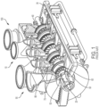
- a multi-stage, centrifugal-flow turbomachine 10 is illustrated in accordance with a conventional design. In some applications, a single stage may be utilized. In other applications, multiple stages may be utilized.
- Such a turbomachine 10 generally includes a shaft 20 supported within a housing 30 by a pair of bearings 40 .
- Turbomachine 10 shown in FIG. 1 includes a plurality of stages to progressively increase the fluid pressure of the working fluid. Each stage is successively arranged along the longitudinal axis of turbomachine 10 and all stages may or may not have similar components operating on the same principle.
- an impeller 50 includes a plurality of rotating blades 60 circumferentially arranged and attached to an impeller hub 70 which is in turn attached to shaft 20 .
- Blades 60 may be optionally attached to a cover disk 65 .
- a plurality of impellers 50 may be spaced apart in multiple stages along the axial length of shaft 20 .
- Rotating blades 60 are fixedly coupled to impeller hub 70 such that rotating blades 60 along with impeller hub 70 rotate with the rotation of shaft 20 .
- Rotating blades 60 rotate downstream of a plurality of stationary vanes or stators 80 attached to a stationary tubular casing.
- the working fluid such as a gas mixture, enters and exits turbomachine 10 in the axial direction of shaft 20 .
- working fluid moves from an inlet end 90 to an outlet end 100 of turbomachine 10 .
- a row of stators 80 provided at inlet end 90 channels the working fluid into a row of rotating blades 60 provided at outlet end 100 of turbomachine 10 .
- Stators 80 extend within the casing for channeling the working fluid to rotating blades 60 .
- Stators 80 are spaced apart circumferentially with equal spacing between individual struts around the perimeter of the casing.
- a diffuser 110 is provided at the outlet of rotating blades 60 for homogenizing the fluid flow coming off rotating blades 60 .
- Diffuser 110 optionally has a plurality of diffuser vanes 120 extending within a casing.
- Diffuser blades 120 are spaced apart circumferentially, typically with equal spacing between individual diffuser blades 120 around the perimeter of the diffuser casing.
- a plurality of return channel vanes 125 are provided at outlet end 100 of a fluid compression stage for channeling the working fluid to rotating blades 60 of the next successive stage.
- the return channel vanes 125 provide the function of stators 80 from the first stage of turbomachine 10 .
- the last impeller in a multi-stage turbomachine typically only has a diffuser, which may be provided with or without the diffuser vanes. The last diffuser channels the flow of working fluid to a discharge casing (volute) having an exit flange for connecting to the discharge pipe.
- turbomachine 10 includes stators 80 at inlet end 90 and diffuser 110 at outlet end 100 .
- turbomachines An important concern in designing turbomachines is controlling the vibration of the rotating blades and the hub throughout the operating range of the turbomachine.
- Rotating blades and disks in turbomachinery are excited into resonant vibrations by a) upstream stator strut and/or vane wakes and potential flow interaction with downstream struts and vanes, b) other inhomogeneities in the flow stream formed by non-uniform circumferential pressure distribution, c) acoustic pulsations either at rotating blade passing frequency and/or d) vortex shedding from stationary vanes, in turn causing coincident acoustic resonance of the gas within the casing.
- Tyler/Sofrin modes may occur due to sound waves at blade passing frequency reflecting off vanes giving spinning modes.
- the acoustic pulsations at the spinning mode in turn can match the mode shape and frequency of the acoustic mode of the cavity at the sides of the impeller, and also match the mode of the impeller structure. This is termed triple coincidence.
- the acoustic pulsations reflect differently off of the stator struts set back further from the impeller and reduce the effective amplitude of the spinning modes.
- impellers either at rotating blades, the hub, or the cover.
- the impeller can be excited to a large amplitude when a modal frequency corresponds to shaft rotational frequency multiplied by the harmonic number of the flow inhomogeneity seen by the blades.
- the number of resonances with an amplitude large enough to cause high cycle fatigue is limited. Since the damage rate from fatigue occurs only if infinite endurance strength of the material is breached, a modest reduction in the vibration amplitude often will eliminate high cycle fatigue as the limiting factor for blade and disk life.
- Another current approach is to reduce the spatial variations in the flow field by directly injecting fluid into low-velocity wakes behind obstructions ( Rao, N. M., Feng, J., Burdisso, R. A, and Ng, W. F., "Active Flow Control to Reduce Fan Blade Vibration and Noise", 5.sup.th AIAA/CEAS Aeroacoustic Conference, American Institute of Aeronautics and Astronautics, May 10-12, 1999 ).
- This approach requires the use of either fluid from the compressor or from an additional external fluid source in relatively large quantities.
- Use of compressor fluid has a detrimental impact on performance.
- the addition of a separate fluid supply adds weight and requires additional power. Both methods have detrimental impacts on performance of the turbomachinery.
- wake filling does not address modal excitation due to bow waves from downstream flow obstructions.
- a similar but more complex interaction is with transverse acoustic modes having a specific number of nodal diameters.
- acoustic gas modes in cavities at sides of impellers, matching rotating acoustic pulsations at impeller blade passing frequency termed Tyler/Sofrin modes, and a matching structural impeller mode give the triple coincidence causing higher resonant response of the impeller, besides increased noise.
- the concern for this coincidence is often difficult to evaluate and to correct unless there is a known failure to modify number of vanes or blades. This coincidence can add to the direct response from either upstream wakes or downstream diffuser vane interacting flow pulsations.
- impeller side cavities are axisymmetric and are set by aerodynamics, so that outer and inner radii define transverse modes with small radial dimensional changes available. Often a minor aerodynamic performance compromise can be used to change designs to avoid serious resonances, e.g. numbers of vanes and blades, changing the response of a matching diameter mode or have a different less responsive mode to alleviate concern.
- turbomachinery e.g. compressors and pumps
- the methods as described could be utilized for any cavity that has diametrical mode shapes, or possibly other patterns of pressure pulsation frequencies. These modification(s) can alleviate if not eliminate concern for any mechanism having structural vibration and/or environmental noise issues.
- US 2014/020975 A1 discloses a volute for a radial turbomachine.
- the turbomachine includes a radial compressor or a radial turbine.
- the volute has a substantially annular cavity which is delimited at least by a first radial side surface. At least one substantially annularly circumferential groove is formed in the side surface.
- US 2013/025967 A1 discloses an acoustic liner for attenuating noise in rotating machinery.
- the acoustic liner may include a plurality of cells coupled together to form an annular cell matrix, the plurality of cells being made of a non-metallic material, for example, plastics, polymers, thermoplastics, or thermosets.
- Each cell of the acoustic liner may be hexagonally-shaped such that the annular cell matrix forms a honeycomb structure.
- EP 0 280 205 A2 discloses a radial compressor with a bladed diffusor connected downstream of the impeller. In the radial compressor the compression shocks occurring in front of the blades on a radial guide vane ring are to be stabilised. To achieve this, the blades of the radial guide vane ring are manufactured with two different alternating lengths and slots, which are connected to a rear reservoir chamber, which are so disposed that the slots are positioned at least approximately at right angles in front of the short blades and extend as far as the side of the leading edges of the nearest long blades.
- an arrangement for intentionally mistuning a cavity formed adjacent an impeller hub and another cavity formed when there is an impeller cover on a turbomachine having "n"-diameter acoustic modes includes at least two bladed elements defined within a perimeter of a casing wall on a hub side of the impeller, wherein the hub side of the impeller is positioned opposite a cover side of the impeller.
- the bladed elements are positioned to mistune the cavities to minimize acoustic pulsations in the cavities.
- the at least two bladed elements are positioned adjacent the impeller.
- n is the n-diameter cavity mode that is to be mistuned.
- Ten bladed elements may have a depth greater than the other ten adjacent bladed elements.
- Ten bladed elements may have a width greater than the other ten adjacent bladed elements.
- the bladed elements may be spaced equidistant from one another.
- the bladed elements may be also defined in the casing wall on the cover side of the impeller.
- a turbomachine in another aspect, includes a casing having an inlet end opposite an outlet end along a longitudinal axis of the casing, a shaft assembly provided within the casing, the shaft assembly extending from the inlet end to the outlet end, a rotor having a plurality of rotating impellers extending radially outward from the shaft assembly, and at least two bladed elements defined within a perimeter of the casing adjacent one of the impellers.
- the bladed elements are positioned to mistune at least one cavity adjacent to the impeller to minimize acoustic pulsations in the cavity for an n-diameter mode, wherein the bladed elements are positioned adjacent to the impeller.
- the bladed elements may be grooves or ridges defined in the casing wall. At least ten bladed elements may be defined in the casing wall. Five bladed elements may have a depth greater than the other five bladed elements. Five bladed elements may have a width greater than the other five bladed elements. The bladed elements may be spaced equidistant from one another. The bladed elements may be defined in the casing wall on a hub side of the impeller. The bladed elements may be defined in the casing wall on a cover side of the impeller. At least sixteen bladed elements may be defined in the casing wall with a specific harmonic mistuning pattern.
- bladed elements may be defined in the casing wall, where "n" is the n-diameter cavity mode that is to be mistuned.
- the bladed elements may be defined in the casing wall on a hub side of the impeller.
- the bladed elements may be defined in the casing wall on a cover side of the impeller.
- the bladed elements may vary in a linear pattern from minimum to maximum size around the circumference to mistune the cavities to minimize acoustic pulsations in the cavity.
- the number of bladed elements can be selected from two up to one less than 2 x "n".
- the mode is a 5-diameter mode
- (2n-1) or nine bladed elements can be selected to mitigate or eliminate the 5-diameter mode within the area containing the bladed elements. If needed, the nine vanes can still be mistuned to give a 2 x "n" harmonic or other mistuning pattern to reduce noise and/or impeller vibration.
- rotating blades or impellers 60 in a conventional turbomachine 10 are excited into resonant vibrations by a) upstream stator strut and/or vane wakes and potential flow interaction with downstream struts and vanes, b) other inhomogeneities in the flow stream formed by non-uniform circumferential pressure distribution, c) acoustic pulsations either at rotating blade passing frequency, multiples of blade passing frequency, and/or from vortex shedding from struts or vanes, in turn causing coincident acoustic resonance of the gas within the casing.
- Rotating blades or impellers 60 can be excited to a large amplitude when a blade modal frequency corresponds to the shaft rotational frequency multiplied by the harmonic number of the flow inhomogeneity seen by the rotating blade or impeller 60 .
- the present disclosure is directed to a method of reducing cavity noise to both reduce noise signature, as well as potential excitation of adjacent bladed disks or impellers from acoustic pressure pulsations.
- the method considers cavities adjacent the impeller as equivalent gas-filled disks with boundary conditions at the sides and ends of the cavities. Acoustic modes within cavities are affected by the swirling flow of the gas within the cavities, differently on the cover side versus the hub side of the turbomachine.
- By adding blade-like elements to replace the basic smooth boundaries of the cavities an effective disk with blades can be modified with intentional mistuning to greatly reduce the response of vibratory modes of the gas in the cavities.
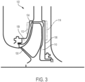
- an impeller 100 is housed within a casing 102 within a turbomachine, such as the turbomachine 10 shown in FIGS. 1 and 2 .
- FIG. 3 illustrates a single stage of a turbomachine; however, one of ordinary skill in the art will understand that specific components illustrated in FIG. 3 can be easily adapted for use in multi-stage turbomachines, such as a multi-stage, centrifugal-flow compressor.
- a plurality of impellers 100 may be spaced apart in multiple stages along the axial length of the shaft.
- the impeller 100 is configured to rotate about the shaft during operation of the turbomachine.
- the impeller 100 is fixedly coupled to the shaft such that the impeller 100 rotates with the rotation of the shaft.
- the casing 102 may extend around a cover side 104 of the impeller 100 and a hub side 106 of the impeller 100 . It is also contemplated that a cover may not be provided with the turbomachine, thereby providing an "open" impeller configuration.
- a first cavity 108 is defined on the cover side 104 of the impeller 100 and a second cavity 110 is defined on the hub side 106 of the impeller 100 .
- the cavities 108, 110 are considered to be equivalent to gas-filled disks provided on the sides of the impeller 100 .
- at least one cavity 108 , 110 is modified so that the surface boundaries of the gas contained within the cavity 108 , 110 has blade-like elements 112 , 114 .
- both cavities 108, 110 are modified so that the surface boundaries of the contained gas within the cavities 108, 110 have blade-like elements 112, 114 (also referred to as "bladed elements").
- blade-like elements 112 , 114 are non-axisymmetric blade-like elements.
- the blade-like elements 112, 114 are grooves and/or ridges spaced around the circumference of the cavities 108 , 110 .
- the blade-like elements 112, 114 may be ribs that extend into the cavity.
- a machining process produces a wave-like length (also referred to as a scallop shape) that is spaced and subsequently modified to give a desired number of effective mistuned elements in the cavities 108, 110 to greatly reduce the response of vibratory modes of the gas in the cavities 108 , 110.
- the number of blade-like elements 112, 114 can be chosen in order to apply desired variations to reduce a response of a particular diameter mode or modes.
- a diameter mode it to be understood to mean a configuration of high acoustic pressure pulsations separated by areas having low acoustic pressure pulsations.
- a 5-diameter acoustic mode would have five areas with high acoustic pressure pulsations alternating with five areas having low acoustic pressure pulsations. Therefore, with reference to FIG. 8 , five of the blade-like elements 112 may have a high acoustic pressure pulsation and the adjacent blade-like elements 112 may have low acoustic pressure pulsations.
- a 5-diameter acoustic mode of the gases within the cavities 108, 110 could be resonant with 15 times the operating speed, the impeller rotating blade passing frequency.
- the spinning modes for blade passing frequency could have five lobes due to 15 impellers interacting with 20 inlet vanes 80 or 20 diffuser vanes 120 .
- a spinning acoustic mode at frequency ⁇ with "n" patterns there may be a variation of pressure in the circumferential direction that is continuous and repeats every 2 ⁇ radians, as defined by the cylindrical geometry. This pressure distribution rotates at ( ⁇ / n) and generates, at every stationary point, a fluctuating pressure at frequency ⁇ .
- the pattern sweeps the cavity annulus walls at a velocity (r ⁇ ⁇ / n), in which r is the radius of the cavity.
- r is the radius of the cavity.
- One or both of the cavities 108 , 110 on the cover side 104 and the hub side 106 could have 10 equally-distant blade-like elements 112 , 114 , such as grooves and/or ridges, machined in the vertical walls of the casing 102 . It is also contemplated that alternative degrees of separation between the blade-like elements 112 , 114 may be used. Intentional mistuning can then be selected to give, for example, a 10-diameter mismatch pattern to greatly reduce the response of vibratory modes of the gas in the cavities 108 , 110 .
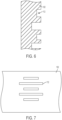
- a pattern with 20 blade-like elements 112 , 114 such as grooves and/or ridges, would give a 10-diameter pattern or, alternatively, could have every second groove in the pattern twice as deep and/or wide as the adjacent groove, as shown in FIGS. 6 and 7 .
- the configuration of the blade-like elements 112 shown in FIGS. 6 and 7 can also be used for the blade-like elements 114 on the hub side 106 of the impeller 100 .
- the configuration of the blade-like elements 112 on the cover side 104 of the impeller 100 could be different from the configuration of the blade-like elements 114 on the hub side 106 of the impeller 100 .
- a pattern could have 20 blade-like elements 112 , 114 , such as grooves, ridges, and/or scallop shapes. Using these patterns of blade-like elements 112 , 114 , acoustic pulsations are reduced and impeller response at 20 times speed is minimized.
- the number of blade-like elements 112 , 114 to mistune may be chosen depending on whether the harmonic of the stationary vanes is greater than or less than the harmonic of the rotating blades.
- the harmonic of vanes is greater than the harmonic of the blades passing by with 2 x "n" blade-like elements 112 , 114
- the spinning modes due to interaction with the rotating blade passing frequency will rotate in an opposite direction to that from the stationary vanes and cancel some of the pulsations.
- 10 blade-like elements 112 , 114 would be used so that spinning modes would be in an opposite direction from those for the 20 stationary vanes.
- the acoustic pulsations due to the blade-like elements 112 , 114 would counter those caused by the vanes.
- the number of stationary vanes is less than the number of rotating blades, four times "n" blade-like elements 112 , 114 would be used.
- the 5-diameter mode is due to the difference of 10 stationary vanes and 15 rotating blades, 20 blade-like elements 112 , 114 would be used so that spinning modes would rotate in opposite directions from those for the ten stationary vanes.
- the acoustic pulsations due to blade-like elements 112 , 114 would counter those caused by the vanes.
- the blade-like elements 112 may be milled into the upstream and downstream diaphragms on the surface of the cavity between the diaphragm and the impeller.
- ten blade-like elements 112 are spaced equally around the circumference.
- five larger blade-like elements 112 are spaced 72 degrees apart from one another.
- Smaller blade-like elements 112 are spaced equally between each of the larger blade-like elements 112 .
- Each blade-like element 112 may be 3,175 cm (1.25 inches) in length located at an inner radius of 12,3825 cm (4.875 inches).
- the larger blade-like elements 112 may be 1,27 cm (0.5 inches) wide and 0,635 cm (0.25 inches) deep.
- the smaller blade-like elements 112 may be 0,635 cm (0.25 inches) wide and 0,3175 cm (0.125 inches) in depth.
- FIG. 9 a similar arrangement of blade-like elements 112 . However, this arrangement includes twenty blade-like elements 112 , including ten larger blade-like elements 112 and ten smaller blade-like elements 112 . It is also to be understood that the blade-like elements 114 may be arranged in similar arrangements as described above.
- blade-like elements 112 , 114 within one of the cavities 108 , 110 , concern for circular modes are eliminated by having a different number of blade-like elements 112 , 114 than the rotating blades in the adjacent disk. Even 1-diameter modes that are of less concern structurally could have blade-like elements 112 , 114 to reduce acoustic pulsations.
- the blade passing frequency pulsations at the sides of the disks excite plate modes with high motion near the outer diameter of the disk.
- the blade-like elements 112 , 114 within the cavities 108 , 110 are spaced and modified depending on the relative phase angles of the acoustic pulsations versus the plate mode.
- Modifications to one or both of the cavities 108 , 110 can be separate to reduce response of disks to one or more gas modes, but the modifications can also be in addition to structural bladed disk mistuning as is used in the prior art for even greater reliability.
- similar blade-like elements such as grooves, ridges, and/or scallop-shaped protrusions, could be provided on the disk or cover 65 of the impeller 100 facing the cavities 108 , 110 to further reduce response.
- these could serve as the blade-like elements that mistune the adjacent fluid-filled cavities.
- fluid encompasses gases, liquids, and gas/liquid mixtures. Acoustic modes would thus be affected by changes in the swirling flow of the gas within the cavities, differently on the cover side versus the hub side of the turbomachine. Cavity modifications could use direct machining and/or welding to form the blade-like element 112 , 114 on the casing 102 or utilize inserts that can be installed and replaced in the cavities 108 , 110 if needed. The blade-like elements 112 , 114 may be worn down during use of the turbomachine and may need to be reformed or redefined.
- blade-like elements could be added to the cavities 108 , 110 to have other function within the cavities 108 , 110 , such as reducing swirl of flow into seals in the turbomachine, reducing thrust load, or reducing flow point when the compressor or turbomachine stall begins at the impeller tip or diffuser entrance.
- the blade-like element arrangement may be used to mistune any cavity or annulus that has diametrical mode shapes or other pattern pressure pulsation frequency, excited by various sources, alleviating concern for structures, including rotating and stationary components, and/or environmental noise issues.
- Similar liquid-handling pumps, axial compressors, fans, as well as steam or gas turbines, are turbomachines that could utilize this disclosed method.
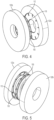
- blade-like elements 112 are defined in a diaphragm wall 118 adjacent to a cover disk 120 on the cover side of the impeller 100 in the turbomachine.
- two diaphragms 122a , 122b define cavities to receive the impeller 100 .
- the blade-like elements 112 may be defined in the diaphragm wall 118 of one or both of the diaphragms 122a, 122b.
- One or more blade-like elements 116 are circumferentially spaced around the diaphragm wall 118 .
- 20 blade-like elements 112 are defined in each diaphragm 122a, 122b at the sides of the impeller 100 .
- the blade-like elements 112 are separated 18 degrees apart from one another. As some acoustic modes are coupled to one another, both cavities and/or the impeller sides could have blade-like elements that are located out-of-phase with each other to provide additional mistuning.
Landscapes
- Engineering & Computer Science (AREA)
- Mechanical Engineering (AREA)
- General Engineering & Computer Science (AREA)
- Physics & Mathematics (AREA)
- Fluid Mechanics (AREA)
- Structures Of Non-Positive Displacement Pumps (AREA)
- Turbine Rotor Nozzle Sealing (AREA)
Description
- This application claims the benefit of
U.S. Provisional Patent Nos. 62/466,774 62/501,852, filed on March 3, 2017 and May 5, 2017 - The present disclosure relates, generally to turbomachines and other mechanisms and, more particularly, to blade-like element arrangements for cavities within a turbomachine adapted for reducing rotor disk excitation using intentional mistuning.
- Turbomachines, such as centrifugal flow compressors, axial flow compressors, and turbines may be utilized in various industries. Centrifugal flow compressors and turbines, in particular, have a widespread use in power stations, jet engine applications, gas turbines, and automotive applications. Centrifugal flow compressors and turbines are also commonly used in large-scale industrial applications, such as air separation plants and hot gas expanders used in the oil refinery industry. Centrifugal compressors are further used in large-scale industrial applications, such as refineries and chemical plants.
- With reference to
FIG. 1 , a multi-stage, centrifugal-flow turbomachine 10 is illustrated in accordance with a conventional design. In some applications, a single stage may be utilized. In other applications, multiple stages may be utilized. Such aturbomachine 10 generally includes ashaft 20 supported within ahousing 30 by a pair ofbearings 40.Turbomachine 10 shown inFIG. 1 includes a plurality of stages to progressively increase the fluid pressure of the working fluid. Each stage is successively arranged along the longitudinal axis ofturbomachine 10 and all stages may or may not have similar components operating on the same principle. - With continued reference to
FIG. 1 , animpeller 50 includes a plurality of rotatingblades 60 circumferentially arranged and attached to animpeller hub 70 which is in turn attached toshaft 20.Blades 60 may be optionally attached to acover disk 65. A plurality ofimpellers 50 may be spaced apart in multiple stages along the axial length ofshaft 20. Rotatingblades 60 are fixedly coupled toimpeller hub 70 such that rotatingblades 60 along withimpeller hub 70 rotate with the rotation ofshaft 20.Rotating blades 60 rotate downstream of a plurality of stationary vanes orstators 80 attached to a stationary tubular casing. The working fluid, such as a gas mixture, enters and exitsturbomachine 10 in the axial direction ofshaft 20. Energy from the working fluid causes a relative motion of rotatingblades 60 with respect tostators 80. In a centrifugal compressor, the cross-sectional area between rotatingblades 60 withinimpeller 50 decreases from an inlet end to a discharge end, such that the working fluid is compressed as it passes acrossimpeller 50. - Referring to
FIG. 2 , working fluid, such as a gas mixture, moves from aninlet end 90 to anoutlet end 100 ofturbomachine 10. A row ofstators 80 provided atinlet end 90 channels the working fluid into a row of rotatingblades 60 provided atoutlet end 100 ofturbomachine 10.Stators 80 extend within the casing for channeling the working fluid to rotatingblades 60.Stators 80 are spaced apart circumferentially with equal spacing between individual struts around the perimeter of the casing. Adiffuser 110 is provided at the outlet of rotatingblades 60 for homogenizing the fluid flow coming off rotatingblades 60. Diffuser 110 optionally has a plurality ofdiffuser vanes 120 extending within a casing.Diffuser blades 120 are spaced apart circumferentially, typically with equal spacing betweenindividual diffuser blades 120 around the perimeter of the diffuser casing. In amulti-stage turbomachine 10, a plurality ofreturn channel vanes 125 are provided atoutlet end 100 of a fluid compression stage for channeling the working fluid to rotatingblades 60 of the next successive stage. In such an embodiment, thereturn channel vanes 125 provide the function ofstators 80 from the first stage ofturbomachine 10. The last impeller in a multi-stage turbomachine typically only has a diffuser, which may be provided with or without the diffuser vanes. The last diffuser channels the flow of working fluid to a discharge casing (volute) having an exit flange for connecting to the discharge pipe. In a single-stage embodiment,turbomachine 10 includesstators 80 atinlet end 90 and diffuser 110 atoutlet end 100. - An important concern in designing turbomachines is controlling the vibration of the rotating blades and the hub throughout the operating range of the turbomachine. Rotating blades and disks in turbomachinery are excited into resonant vibrations by a) upstream stator strut and/or vane wakes and potential flow interaction with downstream struts and vanes, b) other inhomogeneities in the flow stream formed by non-uniform circumferential pressure distribution, c) acoustic pulsations either at rotating blade passing frequency and/or d) vortex shedding from stationary vanes, in turn causing coincident acoustic resonance of the gas within the casing. For example, Tyler/Sofrin modes may occur due to sound waves at blade passing frequency reflecting off vanes giving spinning modes. (Ref. Tyler, J. M., and Sofrin, T. G., 1962, "Axial Flow Compressor Noise Studies", SAE Transactions, Vol.70, pp.309-332.) The acoustic pulsations at the spinning mode in turn can match the mode shape and frequency of the acoustic mode of the cavity at the sides of the impeller, and also match the mode of the impeller structure. This is termed triple coincidence. The acoustic pulsations reflect differently off of the stator struts set back further from the impeller and reduce the effective amplitude of the spinning modes. For example, in an impeller having 15 rotating blades and 20 stator struts, there is a 5-diameter spinning mode at blade passing frequency 15 times the rotor speed. If the 5-diameter structural mode is equal to 20 times the rotating speed, the blade excitation can be lowered by setting half of the stator struts downstream about one-half an acoustic wave length, as wave reflections would result in phase cancellation. One example of such an arrangement is disclosed in
U.S. Patent No. 9,581,034 - These excitations cause cyclic stress, resulting in potentially high cycle fatigue and failure in impellers either at rotating blades, the hub, or the cover. The impeller can be excited to a large amplitude when a modal frequency corresponds to shaft rotational frequency multiplied by the harmonic number of the flow inhomogeneity seen by the blades. Typically, the number of resonances with an amplitude large enough to cause high cycle fatigue is limited. Since the damage rate from fatigue occurs only if infinite endurance strength of the material is breached, a modest reduction in the vibration amplitude often will eliminate high cycle fatigue as the limiting factor for blade and disk life.
- If a critical resonance cannot be avoided, one current practice to overcome these problems is to avoid operation at the resonant frequency by changing the speed rapidly when a resonance is encountered, thereby minimizing the number of fatigue cycles that a blade accumulates during operation. If the number of vibration cycles is minimized, then blade failure is controlled by mechanisms other than downstream wakes, acoustic pulsations, flow inhomogenities, or vortex shedding. However, this practice places undesirable limits on operation of turbomachinery.
- Another current approach is to reduce the spatial variations in the flow field by directly injecting fluid into low-velocity wakes behind obstructions (Rao, N. M., Feng, J., Burdisso, R. A, and Ng, W. F., "Active Flow Control to Reduce Fan Blade Vibration and Noise", 5.sup.th AIAA/CEAS Aeroacoustic Conference, American Institute of Aeronautics and Astronautics, May 10-12, 1999). This approach requires the use of either fluid from the compressor or from an additional external fluid source in relatively large quantities. Use of compressor fluid has a detrimental impact on performance. The addition of a separate fluid supply adds weight and requires additional power. Both methods have detrimental impacts on performance of the turbomachinery. Also, wake filling does not address modal excitation due to bow waves from downstream flow obstructions.
- In recent years, it has been discovered that besides non-uniform flow excitation, such as from stator wakes, acoustic pressure pulsation can be a concern at least for high pressure centrifugal compressor impellers. This has been termed "triple coincidence" and explains rare failures and likely a reason, at least partially, for some previous undocumented failures. Bladed disk interaction resonance can be avoided for centrifugal impellers as needed, depending on vibratory mode involved, available damping, and potential excitation level. Especially for stages having vanes in the diffuser near impeller tips, concern for high cycle fatigue is very high as certain numbers of vanes combined with a number of rotating blades can give a correct phase to excite a highly responding mode. A similar but more complex interaction is with transverse acoustic modes having a specific number of nodal diameters. In this case, acoustic gas modes in cavities at sides of impellers, matching rotating acoustic pulsations at impeller blade passing frequency termed Tyler/Sofrin modes, and a matching structural impeller mode give the triple coincidence causing higher resonant response of the impeller, besides increased noise. The concern for this coincidence is often difficult to evaluate and to correct unless there is a known failure to modify number of vanes or blades. This coincidence can add to the direct response from either upstream wakes or downstream diffuser vane interacting flow pulsations. Dimensions of impeller side cavities are axisymmetric and are set by aerodynamics, so that outer and inner radii define transverse modes with small radial dimensional changes available. Often a minor aerodynamic performance compromise can be used to change designs to avoid serious resonances, e.g. numbers of vanes and blades, changing the response of a matching diameter mode or have a different less responsive mode to alleviate concern. Besides turbomachinery, e.g. compressors and pumps, the methods as described could be utilized for any cavity that has diametrical mode shapes, or possibly other patterns of pressure pulsation frequencies. These modification(s) can alleviate if not eliminate concern for any mechanism having structural vibration and/or environmental noise issues.
US 2014/020975 A1 discloses a volute for a radial turbomachine. The turbomachine includes a radial compressor or a radial turbine. The volute has a substantially annular cavity which is delimited at least by a first radial side surface. At least one substantially annularly circumferential groove is formed in the side surface.
US 2013/025967 A1 discloses an acoustic liner for attenuating noise in rotating machinery. The acoustic liner may include a plurality of cells coupled together to form an annular cell matrix, the plurality of cells being made of a non-metallic material, for example, plastics, polymers, thermoplastics, or thermosets. Each cell of the acoustic liner may be hexagonally-shaped such that the annular cell matrix forms a honeycomb structure.
EP 0 280 205 A2 discloses a radial compressor with a bladed diffusor connected downstream of the impeller. In the radial compressor the compression shocks occurring in front of the blades on a radial guide vane ring are to be stabilised. To achieve this, the blades of the radial guide vane ring are manufactured with two different alternating lengths and slots, which are connected to a rear reservoir chamber, which are so disposed that the slots are positioned at least approximately at right angles in front of the short blades and extend as far as the side of the leading edges of the nearest long blades. - The claimed solution is specified by an arrangement according to claim 1, and by a cavity as claimed in claim 15. Dependent claim specify embodiments thereof. In one aspect of the disclosure, an arrangement for intentionally mistuning a cavity formed adjacent an impeller hub and another cavity formed when there is an impeller cover on a turbomachine having "n"-diameter acoustic modes includes at least two bladed elements defined within a perimeter of a casing wall on a hub side of the impeller, wherein the hub side of the impeller is positioned opposite a cover side of the impeller. The bladed elements are positioned to mistune the cavities to minimize acoustic pulsations in the cavities. The at least two bladed elements are positioned adjacent the impeller.
- In another aspect, two times "n" bladed elements may be defined in the casing wall, wherein "n" is the n-diameter cavity mode that is to be mistuned. The bladed elements may be grooves or ridges defined in the casing wall. For example, of an n-diameter mode where "n"=5, at least 20 bladed elements may be defined in the casing wall. Ten bladed elements may have a depth greater than the other ten adjacent bladed elements. Ten bladed elements may have a width greater than the other ten adjacent bladed elements. The bladed elements may be spaced equidistant from one another. The bladed elements may be also defined in the casing wall on the cover side of the impeller.
- In another aspect, a turbomachine includes a casing having an inlet end opposite an outlet end along a longitudinal axis of the casing, a shaft assembly provided within the casing, the shaft assembly extending from the inlet end to the outlet end, a rotor having a plurality of rotating impellers extending radially outward from the shaft assembly, and at least two bladed elements defined within a perimeter of the casing adjacent one of the impellers. The bladed elements are positioned to mistune at least one cavity adjacent to the impeller to minimize acoustic pulsations in the cavity for an n-diameter mode, wherein the bladed elements are positioned adjacent to the impeller.
- In another aspect, the bladed elements may be grooves or ridges defined in the casing wall. At least ten bladed elements may be defined in the casing wall. Five bladed elements may have a depth greater than the other five bladed elements. Five bladed elements may have a width greater than the other five bladed elements. The bladed elements may be spaced equidistant from one another. The bladed elements may be defined in the casing wall on a hub side of the impeller. The bladed elements may be defined in the casing wall on a cover side of the impeller. At least sixteen bladed elements may be defined in the casing wall with a specific harmonic mistuning pattern.
- In another aspect, up to one less than four times "n" bladed elements may be defined in the casing wall, where "n" is the n-diameter cavity mode that is to be mistuned. The bladed elements may be defined in the casing wall on a hub side of the impeller. The bladed elements may be defined in the casing wall on a cover side of the impeller. The bladed elements may vary in a linear pattern from minimum to maximum size around the circumference to mistune the cavities to minimize acoustic pulsations in the cavity. In another aspect, the number of bladed elements can be selected from two up to one less than 2 x "n". For example, if the mode is a 5-diameter mode, then (2n-1) or nine bladed elements can be selected to mitigate or eliminate the 5-diameter mode within the area containing the bladed elements. If needed, the nine vanes can still be mistuned to give a 2 x "n" harmonic or other mistuning pattern to reduce noise and/or impeller vibration.
- These and other features and characteristics of the turbomachine, as well as the methods of operation and functions of the related elements of structures and the combination of parts and economies of manufacture, will become more apparent upon consideration of the following description and the appended claims with reference to the accompanying drawings, all of which form a part of this specification, wherein like reference numerals designate corresponding parts in the various figures. It is to be expressly understood, however, that the drawings are for the purpose of illustration and description only and are not intended as a definition of the limits of the invention. As used in the specification and the claims, the singular form of "a", "an", and "the" include plural referents unless the context clearly dictates otherwise.
-
-
FIG. 1 is a partial-cutaway perspective view of a multi-stage, centrifugal-flow turbomachine in accordance with a prior art embodiment; -
FIG. 2 is a schematic cross-sectional view of one stage of the turbomachine shown inFIG. 1 ; -
FIG. 3 is a schematic cross-sectional view of one stage of a turbomachine according to the present disclosure; -
FIG. 4 is a front perspective view of an impeller and a cover disk according to the present disclosure; -
FIG. 5 is a rear perspective view of the impeller and the cover disk ofFIG. 4 ; -
FIG. 6 is a cross-sectional view of the casing wall ofFIG. 3 showing a configuration of the blade-like elements according to an aspect of the disclosure; -
FIG. 7 is a front view of the casing wall ofFIG. 3 showing another configuration of the blade-like elements according to an aspect of the disclosure; -
FIG. 8 is a front view of a casing wall including a ten slot arrangement; and -
FIG. 9 is a front view of a casing wall including a twenty slot arrangement. - For purposes of the description hereinafter, the terms "upper", "lower", "right", "left", "vertical", "horizontal", "top", "bottom", "lateral", "longitudinal", and derivatives thereof shall relate to the claimed invention as it is oriented in the drawing figures.
- As described above, rotating blades or
impellers 60 in aconventional turbomachine 10 are excited into resonant vibrations by a) upstream stator strut and/or vane wakes and potential flow interaction with downstream struts and vanes, b) other inhomogeneities in the flow stream formed by non-uniform circumferential pressure distribution, c) acoustic pulsations either at rotating blade passing frequency, multiples of blade passing frequency, and/or from vortex shedding from struts or vanes, in turn causing coincident acoustic resonance of the gas within the casing. Rotating blades orimpellers 60 can be excited to a large amplitude when a blade modal frequency corresponds to the shaft rotational frequency multiplied by the harmonic number of the flow inhomogeneity seen by the rotating blade orimpeller 60. - The present disclosure is directed to a method of reducing cavity noise to both reduce noise signature, as well as potential excitation of adjacent bladed disks or impellers from acoustic pressure pulsations. The method considers cavities adjacent the impeller as equivalent gas-filled disks with boundary conditions at the sides and ends of the cavities. Acoustic modes within cavities are affected by the swirling flow of the gas within the cavities, differently on the cover side versus the hub side of the turbomachine. By adding blade-like elements to replace the basic smooth boundaries of the cavities, an effective disk with blades can be modified with intentional mistuning to greatly reduce the response of vibratory modes of the gas in the cavities.
- With reference to
FIG. 3 , animpeller 100 is housed within acasing 102 within a turbomachine, such as theturbomachine 10 shown inFIGS. 1 and2 .FIG. 3 illustrates a single stage of a turbomachine; however, one of ordinary skill in the art will understand that specific components illustrated inFIG. 3 can be easily adapted for use in multi-stage turbomachines, such as a multi-stage, centrifugal-flow compressor. A plurality ofimpellers 100 may be spaced apart in multiple stages along the axial length of the shaft. Theimpeller 100 is configured to rotate about the shaft during operation of the turbomachine. In one aspect, theimpeller 100 is fixedly coupled to the shaft such that theimpeller 100 rotates with the rotation of the shaft. Thecasing 102 may extend around acover side 104 of theimpeller 100 and ahub side 106 of theimpeller 100. It is also contemplated that a cover may not be provided with the turbomachine, thereby providing an "open" impeller configuration. Afirst cavity 108 is defined on thecover side 104 of theimpeller 100 and asecond cavity 110 is defined on thehub side 106 of theimpeller 100. In one aspect, thecavities impeller 100. In one aspect, at least onecavity cavity like elements cavities cavities like elements 112, 114 (also referred to as "bladed elements"). In one aspect, the blade-like elements - With reference to
FIG. 3 , in one aspect, the blade-like elements cavities like elements cavities cavities like elements FIG. 8 , five of the blade-like elements 112 may have a high acoustic pressure pulsation and the adjacent blade-like elements 112 may have low acoustic pressure pulsations. For example, a 5-diameter acoustic mode of the gases within thecavities inlet vanes diffuser vanes 120. With a spinning acoustic mode at frequency ω with "n" patterns, there may be a variation of pressure in the circumferential direction that is continuous and repeats every 2π radians, as defined by the cylindrical geometry. This pressure distribution rotates at (ω / n) and generates, at every stationary point, a fluctuating pressure at frequency ω. The pattern sweeps the cavity annulus walls at a velocity (r × ω / n), in which r is the radius of the cavity. One or both of thecavities cover side 104 and thehub side 106 could have 10 equally-distant blade-like elements casing 102. It is also contemplated that alternative degrees of separation between the blade-like elements cavities like elements FIGS. 6 and 7 . It is to be understood that the configuration of the blade-like elements 112 shown inFIGS. 6 and 7 can also be used for the blade-like elements 114 on thehub side 106 of theimpeller 100. In another aspect, the configuration of the blade-like elements 112 on thecover side 104 of theimpeller 100 could be different from the configuration of the blade-like elements 114 on thehub side 106 of theimpeller 100. In another aspect, a pattern could have 20 blade-like elements like elements - If needed, the number of blade-
like elements like elements like elements like elements like elements like elements like elements FIG. 8 , the blade-like elements 112 may be milled into the upstream and downstream diaphragms on the surface of the cavity between the diaphragm and the impeller. In this example, ten blade-like elements 112 are spaced equally around the circumference. In this example, five larger blade-like elements 112 are spaced 72 degrees apart from one another. Smaller blade-like elements 112 are spaced equally between each of the larger blade-like elements 112. Each blade-like element 112 may be 3,175 cm (1.25 inches) in length located at an inner radius of 12,3825 cm (4.875 inches). The larger blade-like elements 112 may be 1,27 cm (0.5 inches) wide and 0,635 cm (0.25 inches) deep. The smaller blade-like elements 112 may be 0,635 cm (0.25 inches) wide and 0,3175 cm (0.125 inches) in depth.FIG. 9 a similar arrangement of blade-like elements 112. However, this arrangement includes twenty blade-like elements 112, including ten larger blade-like elements 112 and ten smaller blade-like elements 112. It is also to be understood that the blade-like elements 114 may be arranged in similar arrangements as described above. - In another aspect, by including the blade-
like elements cavities like elements like elements like elements cavities - Modifications to one or both of the
cavities like elements casing 102, similar blade-like elements, such as grooves, ridges, and/or scallop-shaped protrusions, could be provided on the disk or cover 65 of theimpeller 100 facing thecavities like element casing 102 or utilize inserts that can be installed and replaced in thecavities like elements cavities cavities - In other aspects, beside compressor impellers, the blade-like element arrangement may be used to mistune any cavity or annulus that has diametrical mode shapes or other pattern pressure pulsation frequency, excited by various sources, alleviating concern for structures, including rotating and stationary components, and/or environmental noise issues. Similar liquid-handling pumps, axial compressors, fans, as well as steam or gas turbines, are turbomachines that could utilize this disclosed method. Other potential applications for the mistuned blade-like element arrangement to reduce response of acoustic modes include fluid-handling including air mechanisms, such as engines, machinery, fuel cells, piping, ducts, diffusers, nozzles, valves, silencers, mufflers, seals, heat exchangers, airframes, tires and wheels, rockets, combustion chambers, vehicles, speakers, and double-pane windows.
- With reference to
FIGS. 4 and 5 , blade-like elements 112 are defined in adiaphragm wall 118 adjacent to acover disk 120 on the cover side of theimpeller 100 in the turbomachine. In one aspect, twodiaphragms impeller 100. The blade-like elements 112 may be defined in thediaphragm wall 118 of one or both of thediaphragms diaphragm wall 118. In another aspect, 20 blade-like elements 112 are defined in eachdiaphragm impeller 100. In one aspect, the blade-like elements 112 are separated 18 degrees apart from one another. As some acoustic modes are coupled to one another, both cavities and/or the impeller sides could have blade-like elements that are located out-of-phase with each other to provide additional mistuning. - While several aspects of the turbomachine and blade-like elements are shown in the accompanying figures and described in detail hereinabove, other aspects will be apparent to, and readily made by, those skilled in the art without departing from the scope of the claims. Accordingly, the foregoing description is intended to be illustrative rather than restrictive. The invention described hereinabove is defined by the appended claims and all changes to the invention that fall within the meaning of the claims are to be embraced within their scope.
Claims (15)
- An arrangement for intentionally mistuning a cavity formed adjacent an impeller hub and another cavity formed when an impeller cover is provided in a turbomachine having "n"-diameter acoustic modes, the arrangement being characterised byat least two bladed elements (114) defined within a perimeter of a casing wall on a hub side (106) of the impeller (100), wherein the hub side (106) of the impeller (100) is opposite a cover side (104) of the impeller (100),wherein the bladed elements (114) are positioned to mistune the cavities (108, 110) to minimize acoustic pulsations in the cavities (108, 110),wherein the at least two bladed elements (114) are positioned adjacent the impeller (100).
- The arrangement as claimed in claim 1, wherein the bladed elements (114) are grooves or ridges defined in the casing wall.
- The arrangement as claimed in claim 2, wherein at least ten bladed elements (114) are defined in the casing wall with a specific harmonic mistuning pattern.
- The arrangement as claimed in claim 3, wherein two times "n" bladed elements (114) have a depth greater than the other two times "n" bladed elements or two times "n" bladed elements (112) have a width greater than the other two times "n" bladed elements (114).
- The arrangement as claimed in claim 2, wherein the bladed elements (114) are spaced equidistant from one another.
- The arrangement as claimed in claim 1,
wherein further bladed elements (112) are also defined in the casing wall on the cover side (104) of the impeller. - The arrangement as claimed in claim 2, wherein at least eight bladed elements (114) are defined in the casing wall with a predetermined harmonic mistuning pattern with a specific harmonic mistuning pattern.
- The arrangement as claimed in claim 1,wherein (2n-1) bladed elements (114) are defined in one or more of the cavities (108, 110) with or without a mistuning pattern orwherein bladed elements (114) are defined in one or more of the cavities (108, 110)_to mistune an acoustic mode with opposite phase to the structural mode of the rotating element.
- The arrangement as claimed in claim 1, further comprising:a casing (102) having an inlet end opposite an outlet end along a longitudinal axis of the casing (102);a shaft assembly provided within the casing (102), the shaft assembly extending from the inlet end to the outlet end; anda rotor having a plurality of rotating impellers (100) with or without covers extending radially outward from the shaft assembly.
- The arrangement as claimed in claim 9, wherein the bladed elements (114) are grooves or ridges defined in the casing wall, in particular at least four times "n" bladed elements (112) are defined in the casing wall.
- The arrangement as claimed in claim 10, wherein two times "n" bladed elements (114) have a depth greater than the other two times "n" bladed elements or two times "n" bladed elements (114) have a width greater than the other two times "n" bladed elements (114).
- The arrangement as claimed in claim 10, wherein the bladed elements (114) are spaced equidistant from one another.
- The arrangement as claimed in claim 9, whereinfurther bladed elements (112) are defined in the casing wall on a cover side (104) of the impeller (100) orthe bladed elements (112, 114) are provided in at least one of in-phase and out-of-phase with one another in the casing wall and/or at least one of in-phase and out-of-phase on the sides of the impeller hub and a cover.
- The arrangement as claimed in claim 10, wherein at least eight bladed elements (114) are defined in the casing wall with a specific harmonic mistuning pattern.
- A cavity in a gas- or liquid-handling mechanism or device comprising the arrangement as claimed in claim 1.
Applications Claiming Priority (3)
| Application Number | Priority Date | Filing Date | Title |
|---|---|---|---|
| US201762466774P | 2017-03-03 | 2017-03-03 | |
| US201762501852P | 2017-05-05 | 2017-05-05 | |
| PCT/US2018/020880 WO2018161069A1 (en) | 2017-03-03 | 2018-03-05 | Method and arrangement to minimize noise and excitation of structures due to cavity acoustic modes |
Publications (3)
| Publication Number | Publication Date |
|---|---|
| EP3589822A1 EP3589822A1 (en) | 2020-01-08 |
| EP3589822A4 EP3589822A4 (en) | 2020-12-09 |
| EP3589822B1 true EP3589822B1 (en) | 2024-12-25 |
Family
ID=63370515
Family Applications (1)
| Application Number | Title | Priority Date | Filing Date |
|---|---|---|---|
| EP18761518.2A Active EP3589822B1 (en) | 2017-03-03 | 2018-03-05 | Method and arrangement to minimize noise and excitation of structures due to cavity acoustic modes |
Country Status (5)
| Country | Link |
|---|---|
| US (1) | US11255345B2 (en) |
| EP (1) | EP3589822B1 (en) |
| JP (3) | JP2020510783A (en) |
| ES (1) | ES3011837T3 (en) |
| WO (1) | WO2018161069A1 (en) |
Families Citing this family (5)
| Publication number | Priority date | Publication date | Assignee | Title |
|---|---|---|---|---|
| JP6961482B2 (en) * | 2017-12-27 | 2021-11-05 | 三菱重工コンプレッサ株式会社 | Centrifugal compressor and manufacturing method of centrifugal compressor |
| IT201900006674A1 (en) * | 2019-05-09 | 2020-11-09 | Nuovo Pignone Tecnologie Srl | Stator vane for a centrifugal compressor |
| US20230093314A1 (en) * | 2021-09-17 | 2023-03-23 | Carrier Corporation | Passive flow reversal reduction in compressor assembly |
| US12092034B2 (en) | 2022-10-03 | 2024-09-17 | General Electric Company | Circumferentially varying fan casing treatments for reducing fan noise effects |
| US12085023B2 (en) | 2022-10-03 | 2024-09-10 | General Electric Company | Circumferentially varying fan casing treatments for reducing fan noise effects |
Family Cites Families (28)
| Publication number | Priority date | Publication date | Assignee | Title |
|---|---|---|---|---|
| US4063848A (en) | 1976-03-24 | 1977-12-20 | Caterpillar Tractor Co. | Centrifugal compressor vaneless space casing treatment |
| US4212585A (en) | 1978-01-20 | 1980-07-15 | Northern Research And Engineering Corporation | Centrifugal compressor |
| DE3705307A1 (en) * | 1987-02-19 | 1988-09-01 | Kloeckner Humboldt Deutz Ag | RADIAL COMPRESSORS |
| JP2737281B2 (en) | 1989-07-29 | 1998-04-08 | 株式会社島津製作所 | Air regeneration equipment for aircraft |
| JPH0381599A (en) * | 1989-08-25 | 1991-04-05 | Rinnai Corp | Scroll case for centrifugal type blower |
| JPH0361198U (en) * | 1989-10-19 | 1991-06-14 | ||
| CZ48394A3 (en) | 1993-03-04 | 1994-09-14 | Abb Management Ag | Radial-flow compressor with a flow-stabilizing casing |
| US6231301B1 (en) | 1998-12-10 | 2001-05-15 | United Technologies Corporation | Casing treatment for a fluid compressor |
| US6290458B1 (en) * | 1999-09-20 | 2001-09-18 | Hitachi, Ltd. | Turbo machines |
| JP3367607B2 (en) * | 2000-11-10 | 2003-01-14 | 株式会社日立製作所 | Air conditioner indoor unit |
| US6550574B2 (en) * | 2000-12-21 | 2003-04-22 | Dresser-Rand Company | Acoustic liner and a fluid pressurizing device and method utilizing same |
| GB2418956B (en) * | 2003-11-25 | 2006-07-05 | Rolls Royce Plc | A compressor having casing treatment slots |
| FR2869069B1 (en) | 2004-04-20 | 2008-11-21 | Snecma Moteurs Sa | METHOD FOR INTRODUCING A VOLUNTARY CONNECTION TO AN AUBED WHEEL TURBOMACHINE WHEEL WITH VOLUNTARY DISCHARGE |
| JP2006057487A (en) | 2004-08-18 | 2006-03-02 | Mitsubishi Heavy Ind Ltd | Centrifugal compressor |
| US7775758B2 (en) | 2007-02-14 | 2010-08-17 | Pratt & Whitney Canada Corp. | Impeller rear cavity thrust adjustor |
| FR2912789B1 (en) * | 2007-02-21 | 2009-10-02 | Snecma Sa | CARTER WITH CARTER TREATMENT, COMPRESSOR AND TURBOMACHINE COMPRISING SUCH A CARTER. |
| DE102008011644A1 (en) * | 2008-02-28 | 2009-09-03 | Rolls-Royce Deutschland Ltd & Co Kg | Housing structuring for axial compressor in the hub area |
| JP2010025000A (en) * | 2008-07-22 | 2010-02-04 | Hitachi Plant Technologies Ltd | Centrifugal fluid machine |
| US8397506B1 (en) | 2009-06-03 | 2013-03-19 | Steven A. Wright | Turbo-alternator-compressor design for supercritical high density working fluids |
| DE102011005025A1 (en) * | 2011-03-03 | 2012-09-06 | Siemens Aktiengesellschaft | Resonator silencer for a radial flow machine, in particular for a centrifugal compressor |
| US8596413B2 (en) * | 2011-07-25 | 2013-12-03 | Dresser-Rand Company | Acoustic array of polymer material |
| US9581034B2 (en) | 2013-03-14 | 2017-02-28 | Elliott Company | Turbomachinery stationary vane arrangement for disk and blade excitation reduction and phase cancellation |
| CN105358837B (en) * | 2013-07-04 | 2018-03-20 | 三菱重工业株式会社 | Centrifugal compressor |
| US10119554B2 (en) * | 2013-09-11 | 2018-11-06 | Dresser-Rand Company | Acoustic resonators for compressors |
| US9644639B2 (en) | 2014-01-27 | 2017-05-09 | Pratt & Whitney Canada Corp. | Shroud treatment for a centrifugal compressor |
| EP2924245B1 (en) | 2014-03-24 | 2017-03-01 | General Electric Technology GmbH | Steam turbine with resonance chamber |
| US10415391B2 (en) | 2014-05-15 | 2019-09-17 | United Technologies Corporation | Rotor and gas turbine engine including a rotor |
| DE102015209666A1 (en) * | 2015-05-27 | 2016-12-01 | Volkswagen Aktiengesellschaft | compressor |
-
2018
- 2018-03-05 ES ES18761518T patent/ES3011837T3/en active Active
- 2018-03-05 US US16/477,971 patent/US11255345B2/en active Active
- 2018-03-05 EP EP18761518.2A patent/EP3589822B1/en active Active
- 2018-03-05 JP JP2019548031A patent/JP2020510783A/en active Pending
- 2018-03-05 WO PCT/US2018/020880 patent/WO2018161069A1/en not_active Ceased
-
2023
- 2023-01-19 JP JP2023006465A patent/JP2023052513A/en active Pending
-
2024
- 2024-04-02 JP JP2024059480A patent/JP7667895B2/en active Active
Non-Patent Citations (5)
| Title |
|---|
| BRUN KLAUS ET AL: "THE USE OF ACOUSTIC COMB FILTERS TO AVOID CENTRIFUGAL COMPRESSOR DISCHARGE BLADE-PASS PULSATION INDUCED PIPING VIBRATIONS", 31 December 2020 (2020-12-31), pages 1 - 14, XP055968127, Retrieved from the Internet <URL:https://hdl.handle.net/1969.1/196837> [retrieved on 20221005] * |
| FRANK L EISINGER: "Acoustic fatigue of impellers of rotating machinery", JOURNAL OF PRESSURE VESSEL TECHNOLOGY, 31 May 2002 (2002-05-31), pages 1 - 7, XP093164058 * |
| MORFEY ET AL: "Rotating pressure patterns in ducts: Their generation and transmission", JOURNAL OF SOUND AND VIBRATION, ELSEVIER, AMSTERDAM , NL, vol. 1, no. 1, 1 January 1964 (1964-01-01), pages 60 - 87, XP024195202, ISSN: 0022-460X, [retrieved on 19640101], DOI: 10.1016/0022-460X(64)90007-0 * |
| SVEN KÖNIG: "Acoustic eigenmodes in the side cavities of centrifugal compressors", 12 June 2009 (2009-06-12), pages 1 - 11, XP093164057, Retrieved from the Internet <URL:https://doi.org/10.1115/GT2009-59650> * |
| SVEN KÖNIG: "Aeroacoustic phenomena in high-pressure centrifugal compressors - a possible root cause for impeller failures", ASME PAPER, 1 January 2010 (2010-01-01), pages 1 - 20, XP093164056 * |
Also Published As
| Publication number | Publication date |
|---|---|
| JP2020510783A (en) | 2020-04-09 |
| JP7667895B2 (en) | 2025-04-23 |
| WO2018161069A1 (en) | 2018-09-07 |
| JP2023052513A (en) | 2023-04-11 |
| EP3589822A4 (en) | 2020-12-09 |
| EP3589822A1 (en) | 2020-01-08 |
| US11255345B2 (en) | 2022-02-22 |
| JP2024099533A (en) | 2024-07-25 |
| ES3011837T3 (en) | 2025-04-08 |
| US20190331134A1 (en) | 2019-10-31 |
Similar Documents
| Publication | Publication Date | Title |
|---|---|---|
| JP7667895B2 (en) | Turbomachinery | |
| US9581034B2 (en) | Turbomachinery stationary vane arrangement for disk and blade excitation reduction and phase cancellation | |
| US20120272663A1 (en) | Centrifugal compressor assembly with stator vane row | |
| EP3222854B1 (en) | Axi-centrifugal compressor | |
| KR20090092682A (en) | Centrifugal compressor | |
| JP2009264205A (en) | Centrifugal compressor | |
| JP2017519154A (en) | Diffuser for centrifugal compressor | |
| US3378229A (en) | Radial flow turbine | |
| KR101896436B1 (en) | Compressor Having Reinforce Disk, And Gas Turbine Having The Same | |
| JP2012188957A (en) | Axial flow turbine | |
| EP3222811A1 (en) | Damping vibrations in a gas turbine | |
| US11168606B2 (en) | Turbine | |
| EP1722069A1 (en) | Combustion turbine engine | |
| EP2960432B1 (en) | Rotor and gas turbine engine including a rotor | |
| US12480530B2 (en) | Centrifugal acceleration stabilizer | |
| JP2011027101A (en) | Turbo pump | |
| US7670110B2 (en) | Sideload vanes for fluid pump | |
| US12320304B2 (en) | Gas turbine engine including a compressor bleed air system | |
| Kushner | Quadruple Flow and Acoustic Coincident Resonance of Rotating Bladed Disks Interacting With Stationary Elements |
Legal Events
| Date | Code | Title | Description |
|---|---|---|---|
| STAA | Information on the status of an ep patent application or granted ep patent |
Free format text: STATUS: THE INTERNATIONAL PUBLICATION HAS BEEN MADE |
|
| PUAI | Public reference made under article 153(3) epc to a published international application that has entered the european phase |
Free format text: ORIGINAL CODE: 0009012 |
|
| STAA | Information on the status of an ep patent application or granted ep patent |
Free format text: STATUS: REQUEST FOR EXAMINATION WAS MADE |
|
| 17P | Request for examination filed |
Effective date: 20191002 |
|
| AK | Designated contracting states |
Kind code of ref document: A1 Designated state(s): AL AT BE BG CH CY CZ DE DK EE ES FI FR GB GR HR HU IE IS IT LI LT LU LV MC MK MT NL NO PL PT RO RS SE SI SK SM TR |
|
| AX | Request for extension of the european patent |
Extension state: BA ME |
|
| DAV | Request for validation of the european patent (deleted) | ||
| DAX | Request for extension of the european patent (deleted) | ||
| REG | Reference to a national code |
Ref country code: DE Free format text: PREVIOUS MAIN CLASS: F01D0025040000 Ref country code: DE Ref legal event code: R079 Ref document number: 602018077927 Country of ref document: DE Free format text: PREVIOUS MAIN CLASS: F01D0025040000 Ipc: F04D0029660000 |
|
| A4 | Supplementary search report drawn up and despatched |
Effective date: 20201106 |
|
| RIC1 | Information provided on ipc code assigned before grant |
Ipc: F04D 29/44 20060101ALI20201102BHEP Ipc: F01D 9/04 20060101ALI20201102BHEP Ipc: F04D 29/66 20060101AFI20201102BHEP Ipc: F04D 29/40 20060101ALI20201102BHEP |
|
| STAA | Information on the status of an ep patent application or granted ep patent |
Free format text: STATUS: EXAMINATION IS IN PROGRESS |
|
| 17Q | First examination report despatched |
Effective date: 20221013 |
|
| P01 | Opt-out of the competence of the unified patent court (upc) registered |
Effective date: 20230526 |
|
| GRAP | Despatch of communication of intention to grant a patent |
Free format text: ORIGINAL CODE: EPIDOSNIGR1 |
|
| STAA | Information on the status of an ep patent application or granted ep patent |
Free format text: STATUS: GRANT OF PATENT IS INTENDED |
|
| INTG | Intention to grant announced |
Effective date: 20240709 |
|
| GRAJ | Information related to disapproval of communication of intention to grant by the applicant or resumption of examination proceedings by the epo deleted |
Free format text: ORIGINAL CODE: EPIDOSDIGR1 |
|
| STAA | Information on the status of an ep patent application or granted ep patent |
Free format text: STATUS: EXAMINATION IS IN PROGRESS |
|
| GRAP | Despatch of communication of intention to grant a patent |
Free format text: ORIGINAL CODE: EPIDOSNIGR1 |
|
| STAA | Information on the status of an ep patent application or granted ep patent |
Free format text: STATUS: GRANT OF PATENT IS INTENDED |
|
| GRAS | Grant fee paid |
Free format text: ORIGINAL CODE: EPIDOSNIGR3 |
|
| INTC | Intention to grant announced (deleted) | ||
| GRAA | (expected) grant |
Free format text: ORIGINAL CODE: 0009210 |
|
| STAA | Information on the status of an ep patent application or granted ep patent |
Free format text: STATUS: THE PATENT HAS BEEN GRANTED |
|
| INTG | Intention to grant announced |
Effective date: 20241025 |
|
| AK | Designated contracting states |
Kind code of ref document: B1 Designated state(s): AL AT BE BG CH CY CZ DE DK EE ES FI FR GB GR HR HU IE IS IT LI LT LU LV MC MK MT NL NO PL PT RO RS SE SI SK SM TR |
|
| REG | Reference to a national code |
Ref country code: GB Ref legal event code: FG4D |
|
| REG | Reference to a national code |
Ref country code: CH Ref legal event code: EP |
|
| REG | Reference to a national code |
Ref country code: DE Ref legal event code: R096 Ref document number: 602018077927 Country of ref document: DE |
|
| REG | Reference to a national code |
Ref country code: IE Ref legal event code: FG4D |
|
| REG | Reference to a national code |
Ref country code: NL Ref legal event code: FP |
|
| REG | Reference to a national code |
Ref country code: ES Ref legal event code: FG2A Ref document number: 3011837 Country of ref document: ES Kind code of ref document: T3 Effective date: 20250408 |
|
| REG | Reference to a national code |
Ref country code: LT Ref legal event code: MG9D |
|
| PG25 | Lapsed in a contracting state [announced via postgrant information from national office to epo] |
Ref country code: HR Free format text: LAPSE BECAUSE OF FAILURE TO SUBMIT A TRANSLATION OF THE DESCRIPTION OR TO PAY THE FEE WITHIN THE PRESCRIBED TIME-LIMIT Effective date: 20241225 |
|
| PG25 | Lapsed in a contracting state [announced via postgrant information from national office to epo] |
Ref country code: FI Free format text: LAPSE BECAUSE OF FAILURE TO SUBMIT A TRANSLATION OF THE DESCRIPTION OR TO PAY THE FEE WITHIN THE PRESCRIBED TIME-LIMIT Effective date: 20241225 |
|
| PG25 | Lapsed in a contracting state [announced via postgrant information from national office to epo] |
Ref country code: BG Free format text: LAPSE BECAUSE OF FAILURE TO SUBMIT A TRANSLATION OF THE DESCRIPTION OR TO PAY THE FEE WITHIN THE PRESCRIBED TIME-LIMIT Effective date: 20241225 |
|
| PG25 | Lapsed in a contracting state [announced via postgrant information from national office to epo] |
Ref country code: NO Free format text: LAPSE BECAUSE OF FAILURE TO SUBMIT A TRANSLATION OF THE DESCRIPTION OR TO PAY THE FEE WITHIN THE PRESCRIBED TIME-LIMIT Effective date: 20250325 |
|
| PG25 | Lapsed in a contracting state [announced via postgrant information from national office to epo] |
Ref country code: LV Free format text: LAPSE BECAUSE OF FAILURE TO SUBMIT A TRANSLATION OF THE DESCRIPTION OR TO PAY THE FEE WITHIN THE PRESCRIBED TIME-LIMIT Effective date: 20241225 Ref country code: GR Free format text: LAPSE BECAUSE OF FAILURE TO SUBMIT A TRANSLATION OF THE DESCRIPTION OR TO PAY THE FEE WITHIN THE PRESCRIBED TIME-LIMIT Effective date: 20250326 |
|
| PG25 | Lapsed in a contracting state [announced via postgrant information from national office to epo] |
Ref country code: RS Free format text: LAPSE BECAUSE OF FAILURE TO SUBMIT A TRANSLATION OF THE DESCRIPTION OR TO PAY THE FEE WITHIN THE PRESCRIBED TIME-LIMIT Effective date: 20250325 |
|
| REG | Reference to a national code |
Ref country code: AT Ref legal event code: MK05 Ref document number: 1754369 Country of ref document: AT Kind code of ref document: T Effective date: 20241225 |
|
| PG25 | Lapsed in a contracting state [announced via postgrant information from national office to epo] |
Ref country code: SM Free format text: LAPSE BECAUSE OF FAILURE TO SUBMIT A TRANSLATION OF THE DESCRIPTION OR TO PAY THE FEE WITHIN THE PRESCRIBED TIME-LIMIT Effective date: 20241225 |
|
| PG25 | Lapsed in a contracting state [announced via postgrant information from national office to epo] |
Ref country code: PL Free format text: LAPSE BECAUSE OF FAILURE TO SUBMIT A TRANSLATION OF THE DESCRIPTION OR TO PAY THE FEE WITHIN THE PRESCRIBED TIME-LIMIT Effective date: 20241225 |
|
| PGFP | Annual fee paid to national office [announced via postgrant information from national office to epo] |
Ref country code: ES Payment date: 20250414 Year of fee payment: 8 |
|
| PG25 | Lapsed in a contracting state [announced via postgrant information from national office to epo] |
Ref country code: IS Free format text: LAPSE BECAUSE OF FAILURE TO SUBMIT A TRANSLATION OF THE DESCRIPTION OR TO PAY THE FEE WITHIN THE PRESCRIBED TIME-LIMIT Effective date: 20250425 |
|
| PG25 | Lapsed in a contracting state [announced via postgrant information from national office to epo] |
Ref country code: PT Free format text: LAPSE BECAUSE OF FAILURE TO SUBMIT A TRANSLATION OF THE DESCRIPTION OR TO PAY THE FEE WITHIN THE PRESCRIBED TIME-LIMIT Effective date: 20250428 |
|
| PG25 | Lapsed in a contracting state [announced via postgrant information from national office to epo] |
Ref country code: EE Free format text: LAPSE BECAUSE OF FAILURE TO SUBMIT A TRANSLATION OF THE DESCRIPTION OR TO PAY THE FEE WITHIN THE PRESCRIBED TIME-LIMIT Effective date: 20241225 |
|
| PGFP | Annual fee paid to national office [announced via postgrant information from national office to epo] |
Ref country code: CH Payment date: 20250401 Year of fee payment: 8 |
|
| PG25 | Lapsed in a contracting state [announced via postgrant information from national office to epo] |
Ref country code: AT Free format text: LAPSE BECAUSE OF FAILURE TO SUBMIT A TRANSLATION OF THE DESCRIPTION OR TO PAY THE FEE WITHIN THE PRESCRIBED TIME-LIMIT Effective date: 20241225 Ref country code: RO Free format text: LAPSE BECAUSE OF FAILURE TO SUBMIT A TRANSLATION OF THE DESCRIPTION OR TO PAY THE FEE WITHIN THE PRESCRIBED TIME-LIMIT Effective date: 20241225 |
|
| PG25 | Lapsed in a contracting state [announced via postgrant information from national office to epo] |
Ref country code: SK Free format text: LAPSE BECAUSE OF FAILURE TO SUBMIT A TRANSLATION OF THE DESCRIPTION OR TO PAY THE FEE WITHIN THE PRESCRIBED TIME-LIMIT Effective date: 20241225 |
|
| PG25 | Lapsed in a contracting state [announced via postgrant information from national office to epo] |
Ref country code: CZ Free format text: LAPSE BECAUSE OF FAILURE TO SUBMIT A TRANSLATION OF THE DESCRIPTION OR TO PAY THE FEE WITHIN THE PRESCRIBED TIME-LIMIT Effective date: 20241225 |
|
| PG25 | Lapsed in a contracting state [announced via postgrant information from national office to epo] |
Ref country code: SE Free format text: LAPSE BECAUSE OF FAILURE TO SUBMIT A TRANSLATION OF THE DESCRIPTION OR TO PAY THE FEE WITHIN THE PRESCRIBED TIME-LIMIT Effective date: 20241225 |
|
| REG | Reference to a national code |
Ref country code: DE Ref legal event code: R097 Ref document number: 602018077927 Country of ref document: DE |
|
| PG25 | Lapsed in a contracting state [announced via postgrant information from national office to epo] |
Ref country code: DK Free format text: LAPSE BECAUSE OF FAILURE TO SUBMIT A TRANSLATION OF THE DESCRIPTION OR TO PAY THE FEE WITHIN THE PRESCRIBED TIME-LIMIT Effective date: 20241225 |
|
| PG25 | Lapsed in a contracting state [announced via postgrant information from national office to epo] |
Ref country code: MC Free format text: LAPSE BECAUSE OF FAILURE TO SUBMIT A TRANSLATION OF THE DESCRIPTION OR TO PAY THE FEE WITHIN THE PRESCRIBED TIME-LIMIT Effective date: 20241225 |
|
| PLBE | No opposition filed within time limit |
Free format text: ORIGINAL CODE: 0009261 |
|
| STAA | Information on the status of an ep patent application or granted ep patent |
Free format text: STATUS: NO OPPOSITION FILED WITHIN TIME LIMIT |
|
| REG | Reference to a national code |
Ref country code: CH Ref legal event code: L10 Free format text: ST27 STATUS EVENT CODE: U-0-0-L10-L00 (AS PROVIDED BY THE NATIONAL OFFICE) Effective date: 20251105 |
|
| PG25 | Lapsed in a contracting state [announced via postgrant information from national office to epo] |
Ref country code: LU Free format text: LAPSE BECAUSE OF NON-PAYMENT OF DUE FEES Effective date: 20250305 |
|
| 26N | No opposition filed |
Effective date: 20250926 |
|
| REG | Reference to a national code |
Ref country code: BE Ref legal event code: MM Effective date: 20250331 |
|
| PGFP | Annual fee paid to national office [announced via postgrant information from national office to epo] |
Ref country code: FR Payment date: 20251231 Year of fee payment: 9 |
|
| PG25 | Lapsed in a contracting state [announced via postgrant information from national office to epo] |
Ref country code: BE Free format text: LAPSE BECAUSE OF NON-PAYMENT OF DUE FEES Effective date: 20250331 |
|
| PG25 | Lapsed in a contracting state [announced via postgrant information from national office to epo] |
Ref country code: IE Free format text: LAPSE BECAUSE OF NON-PAYMENT OF DUE FEES Effective date: 20250305 |
|
| PGFP | Annual fee paid to national office [announced via postgrant information from national office to epo] |
Ref country code: NL Payment date: 20260106 Year of fee payment: 9 |
|
| REG | Reference to a national code |
Ref country code: CH Ref legal event code: U11 Free format text: ST27 STATUS EVENT CODE: U-0-0-U10-U11 (AS PROVIDED BY THE NATIONAL OFFICE) Effective date: 20260401 |
|
| PGFP | Annual fee paid to national office [announced via postgrant information from national office to epo] |
Ref country code: GB Payment date: 20260106 Year of fee payment: 9 |
|
| PGFP | Annual fee paid to national office [announced via postgrant information from national office to epo] |
Ref country code: DE Payment date: 20260102 Year of fee payment: 9 |
|
| PGFP | Annual fee paid to national office [announced via postgrant information from national office to epo] |
Ref country code: IT Payment date: 20260220 Year of fee payment: 9 |