EP3589101B1 - Heat transfer devices and methods of cooling heat sources - Google Patents
Heat transfer devices and methods of cooling heat sources Download PDFInfo
- Publication number
- EP3589101B1 EP3589101B1 EP19181224.7A EP19181224A EP3589101B1 EP 3589101 B1 EP3589101 B1 EP 3589101B1 EP 19181224 A EP19181224 A EP 19181224A EP 3589101 B1 EP3589101 B1 EP 3589101B1
- Authority
- EP
- European Patent Office
- Prior art keywords
- coolant
- storage chamber
- additional
- heat transfer
- barrier element
- Prior art date
- Legal status (The legal status is an assumption and is not a legal conclusion. Google has not performed a legal analysis and makes no representation as to the accuracy of the status listed.)
- Active
Links
Images





Classifications
-
- F—MECHANICAL ENGINEERING; LIGHTING; HEATING; WEAPONS; BLASTING
- F28—HEAT EXCHANGE IN GENERAL
- F28C—HEAT-EXCHANGE APPARATUS, NOT PROVIDED FOR IN ANOTHER SUBCLASS, IN WHICH THE HEAT-EXCHANGE MEDIA COME INTO DIRECT CONTACT WITHOUT CHEMICAL INTERACTION
- F28C3/00—Other direct-contact heat-exchange apparatus
- F28C3/06—Other direct-contact heat-exchange apparatus the heat-exchange media being a liquid and a gas or vapour
- F28C3/08—Other direct-contact heat-exchange apparatus the heat-exchange media being a liquid and a gas or vapour with change of state, e.g. absorption, evaporation, condensation
-
- F—MECHANICAL ENGINEERING; LIGHTING; HEATING; WEAPONS; BLASTING
- F28—HEAT EXCHANGE IN GENERAL
- F28C—HEAT-EXCHANGE APPARATUS, NOT PROVIDED FOR IN ANOTHER SUBCLASS, IN WHICH THE HEAT-EXCHANGE MEDIA COME INTO DIRECT CONTACT WITHOUT CHEMICAL INTERACTION
- F28C3/00—Other direct-contact heat-exchange apparatus
- F28C3/005—Other direct-contact heat-exchange apparatus one heat-exchange medium being a solid
-
- H—ELECTRICITY
- H05—ELECTRIC TECHNIQUES NOT OTHERWISE PROVIDED FOR
- H05K—PRINTED CIRCUITS; CASINGS OR CONSTRUCTIONAL DETAILS OF ELECTRIC APPARATUS; MANUFACTURE OF ASSEMBLAGES OF ELECTRICAL COMPONENTS
- H05K7/00—Constructional details common to different types of electric apparatus
- H05K7/20—Modifications to facilitate cooling, ventilating, or heating
- H05K7/20218—Modifications to facilitate cooling, ventilating, or heating using a liquid coolant without phase change in electronic enclosures
- H05K7/20272—Accessories for moving fluid, for expanding fluid, for connecting fluid conduits, for distributing fluid, for removing gas or for preventing leakage, e.g. pumps, tanks or manifolds
-
- H—ELECTRICITY
- H05—ELECTRIC TECHNIQUES NOT OTHERWISE PROVIDED FOR
- H05K—PRINTED CIRCUITS; CASINGS OR CONSTRUCTIONAL DETAILS OF ELECTRIC APPARATUS; MANUFACTURE OF ASSEMBLAGES OF ELECTRICAL COMPONENTS
- H05K7/00—Constructional details common to different types of electric apparatus
- H05K7/20—Modifications to facilitate cooling, ventilating, or heating
- H05K7/2029—Modifications to facilitate cooling, ventilating, or heating using a liquid coolant with phase change in electronic enclosures
- H05K7/20336—Heat pipes, e.g. wicks or capillary pumps
-
- H—ELECTRICITY
- H05—ELECTRIC TECHNIQUES NOT OTHERWISE PROVIDED FOR
- H05K—PRINTED CIRCUITS; CASINGS OR CONSTRUCTIONAL DETAILS OF ELECTRIC APPARATUS; MANUFACTURE OF ASSEMBLAGES OF ELECTRICAL COMPONENTS
- H05K7/00—Constructional details common to different types of electric apparatus
- H05K7/20—Modifications to facilitate cooling, ventilating, or heating
- H05K7/2029—Modifications to facilitate cooling, ventilating, or heating using a liquid coolant with phase change in electronic enclosures
- H05K7/20372—Cryogenic cooling; Nitrogen liquid cooling
-
- F—MECHANICAL ENGINEERING; LIGHTING; HEATING; WEAPONS; BLASTING
- F25—REFRIGERATION OR COOLING; COMBINED HEATING AND REFRIGERATION SYSTEMS; HEAT PUMP SYSTEMS; MANUFACTURE OR STORAGE OF ICE; LIQUEFACTION SOLIDIFICATION OF GASES
- F25B—REFRIGERATION MACHINES, PLANTS OR SYSTEMS; COMBINED HEATING AND REFRIGERATION SYSTEMS; HEAT PUMP SYSTEMS
- F25B19/00—Machines, plants or systems, using evaporation of a refrigerant but without recovery of the vapour
- F25B19/005—Machines, plants or systems, using evaporation of a refrigerant but without recovery of the vapour the refrigerant being a liquefied gas
-
- F—MECHANICAL ENGINEERING; LIGHTING; HEATING; WEAPONS; BLASTING
- F25—REFRIGERATION OR COOLING; COMBINED HEATING AND REFRIGERATION SYSTEMS; HEAT PUMP SYSTEMS; MANUFACTURE OR STORAGE OF ICE; LIQUEFACTION SOLIDIFICATION OF GASES
- F25B—REFRIGERATION MACHINES, PLANTS OR SYSTEMS; COMBINED HEATING AND REFRIGERATION SYSTEMS; HEAT PUMP SYSTEMS
- F25B2400/00—Component parts or details not otherwise provided for in this subclass
- F25B2400/12—Inflammable refrigerants
-
- F—MECHANICAL ENGINEERING; LIGHTING; HEATING; WEAPONS; BLASTING
- F28—HEAT EXCHANGE IN GENERAL
- F28D—HEAT-EXCHANGE APPARATUS, NOT PROVIDED FOR IN ANOTHER SUBCLASS, IN WHICH THE HEAT-EXCHANGE MEDIA DO NOT COME INTO DIRECT CONTACT
- F28D21/00—Heat-exchange apparatus not covered by any of the groups F28D1/00 - F28D20/00
- F28D2021/0019—Other heat exchangers for particular applications; Heat exchange systems not otherwise provided for
- F28D2021/0028—Other heat exchangers for particular applications; Heat exchange systems not otherwise provided for for cooling heat generating elements, e.g. for cooling electronic components or electric devices
-
- F—MECHANICAL ENGINEERING; LIGHTING; HEATING; WEAPONS; BLASTING
- F28—HEAT EXCHANGE IN GENERAL
- F28F—DETAILS OF HEAT-EXCHANGE AND HEAT-TRANSFER APPARATUS, OF GENERAL APPLICATION
- F28F2250/00—Arrangements for modifying the flow of the heat exchange media, e.g. flow guiding means; Particular flow patterns
- F28F2250/10—Particular pattern of flow of the heat exchange media
-
- H—ELECTRICITY
- H05—ELECTRIC TECHNIQUES NOT OTHERWISE PROVIDED FOR
- H05K—PRINTED CIRCUITS; CASINGS OR CONSTRUCTIONAL DETAILS OF ELECTRIC APPARATUS; MANUFACTURE OF ASSEMBLAGES OF ELECTRICAL COMPONENTS
- H05K7/00—Constructional details common to different types of electric apparatus
- H05K7/20—Modifications to facilitate cooling, ventilating, or heating
- H05K7/20218—Modifications to facilitate cooling, ventilating, or heating using a liquid coolant without phase change in electronic enclosures
- H05K7/20281—Thermal management, e.g. liquid flow control
-
- H—ELECTRICITY
- H05—ELECTRIC TECHNIQUES NOT OTHERWISE PROVIDED FOR
- H05K—PRINTED CIRCUITS; CASINGS OR CONSTRUCTIONAL DETAILS OF ELECTRIC APPARATUS; MANUFACTURE OF ASSEMBLAGES OF ELECTRICAL COMPONENTS
- H05K7/00—Constructional details common to different types of electric apparatus
- H05K7/20—Modifications to facilitate cooling, ventilating, or heating
- H05K7/2029—Modifications to facilitate cooling, ventilating, or heating using a liquid coolant with phase change in electronic enclosures
- H05K7/20327—Accessories for moving fluid, for connecting fluid conduits, for distributing fluid or for preventing leakage, e.g. pumps, tanks or manifolds
-
- H—ELECTRICITY
- H05—ELECTRIC TECHNIQUES NOT OTHERWISE PROVIDED FOR
- H05K—PRINTED CIRCUITS; CASINGS OR CONSTRUCTIONAL DETAILS OF ELECTRIC APPARATUS; MANUFACTURE OF ASSEMBLAGES OF ELECTRICAL COMPONENTS
- H05K7/00—Constructional details common to different types of electric apparatus
- H05K7/20—Modifications to facilitate cooling, ventilating, or heating
- H05K7/2029—Modifications to facilitate cooling, ventilating, or heating using a liquid coolant with phase change in electronic enclosures
- H05K7/20381—Thermal management, e.g. evaporation control
Definitions
- the present disclosure relates to heat transfer devices.
- Heat transfer devices, electronic devices, and methods for cooling a heat source are disclosed.
- a heat transfer device includes all the features disclosed in the appended set of claims 1-11.
- a method of cooling a heat source is as defined in claims 12-14.
- Document US4126017 in accordance with its abstract, relates to a miniature open circuit refrigerator of the Joule-Thompson type which functions as a demand cryostat by virtue of a pressure-operated refrigerant supply control.
- the refrigerant fluid under high pressure is introduced at a first relatively rapid flow rate into the cryostat through a calibrated opening that is fully open during the initial or start-up period of the device, for rapid cool down.
- This calibrated opening is thereafter at least partially closed by a valve which is urged open by a spring and which is urged closed, against the action of the spring, by a bellows containing a gas at high pressure and which is exposed on its outer side to at least a portion of the pressure of the refrigerant fluid.
- the bellows Upon the fall in pressure of the stored refrigerant fluid, toward the end of the start-up, the bellows expands so as at least partially to close the valve, thereby to decrease the flow of refrigerant during the final portion of the cool-down period and during the steady state or on-stream operation of the device.
- the invention is particularly applicable for the rapid cool down of infrared detection probes.
- Document CN107846814 in accordance with its abstract, relates to an information pushing system.
- the system comprises a cloud server, and an information publishing client connected with the cloud server;
- the information publishing client comprises an input unit for inputting information, an electronic map unit for generating geographic range information, time range information and to-be-published information according to the input information; and a communication unit for sending the geographic range information, the time range information and the to-be-published information;
- the cloud server screens out a mobile client satisfying the condition according to the geographic range information, the time range information and the to-be-published information, and then sends the to-be-published information to the screened mobile client in the time range information;
- a box body further contains a radiating tank and other radiating parts.
- Document GB1164276 in accordance with its abstract, relates to a Joule Thompson cooling apparatus in which a gas is liquefied to cool a load and the compressed gas supply to the Joule Thompson nozzle is modulated by valve control.
- a control unit is included in the line between a bottle of compressed gas and the Joule Thompson apparatus.
- a valve is influenced by springs, downstream gas pressure on a face, and a bellows which is connected with a bulb in the Joule Thompson cooler and towards which the nozzle is directed.
- a metal rod is arranged with respect to the nozzle and has such a coefficient of expansion relative to the remainder of the cooler that rising liquid level in the latter causes the flow cross-section of the nozzle to be reduced.
- a bellows in the cooler contracts with rising liquid level to operate a baffle to reduce the flow cross section of the nozzle.
- the Joule Thompson cooler together with its flow control may be incorporated in a cold gas engine as a second cooling stage.
- Document US6889763 in accordance with its abstract, relates to a resist coated wafers which are rapidly and uniformly cooled by a fluid that has been cooled through the Joule-Thompson effect.
- Fluid from a high-pressure reservoir is vented into a chamber that contains the substrates.
- the temperature of the cooling fluid entering the chamber can be controlled.
- the average temperature difference between the fluid in the chamber and the substrates may be limited, whereby more uniform cooling is obtained.
- the chamber pressure is lower than that in the high-pressure reservoir, the chamber pressure may still be substantially greater than atmospheric.
- An elevated chamber pressure raises the specific heat and residence time of the fluid in the chamber, which also promotes uniform cooling.
- Cooling circuits may include circuits that perform reverse-flow heat exchange to pre-cool incoming refrigerant and also cooling circuits that have heat bridges disposed thereon to assist in such heat exchange.
- the Joule-Thomson cryogenic refrigeration system includes a demand-flow Joule-Thomson expansion valve disposed in a cryostat of the refrigeration system.
- the expansion valve has an adjustable orifice that controls the flow of compressed gas therethrough and induces cooling and partial liquefaction of the gas.
- a recuperative heat exchanger is disposed in the cryostat and coupled to the expansion valve.
- a thermostatically self-regulating mechanism is disposed in the cryostat and coupled to the J-T expansion valve.
- the thermostatically self-regulating mechanism automatically adjusts the cross-sectional area of the adjustable valve orifice in response to environmental temperature changes and changes in power dissipated at a cold head.
- a temperature sensing and adjusting mechanism is coupled to the cold head for adjusting the temperature of the cold head in response to the change in heat flow in the cold head.
- the temperature sensing and adjusting mechanism comprises a temperature sensitive diode, a wound wire heater, and an electrical feedback control circuit coupling the diode to the heater.
- An absolute pressure relief valve is interposed between the output of the cryostat and an exhaust port for maintaining a constant exhaust temperature of the refrigeration system, independent of changes in atmospheric pressure.
- Document US2012/103571 in accordance with its abstract, relates to a structure of heat dissipation of an electronic device which includes at least one heat pipe and a cooler.
- the heat pipe has a condensation end and an evaporation end opposite to each other, and the evaporation end is disposed on a heat generating element of the electronic device.
- the cooler is disposed on a rack and has a chamber therein, and the chamber has an inner shell having a cooling fluid therein.
- the condensation end of the heat pipe is inserted into the cooler and positioned into the inner shell.
- the evaporation end absorbs the heat energy of the heat generating element, and transfers the heat energy to the condensation end, such that the cooling fluid dissipates the heat energy of the condensation end.
- Document US 2017/102191 in accordance with its abstract, relates to a heat storage apparatus which includes: a first tank, a second tank that is provided above the first tank, an on-off valve and a heat storage solution that is accommodated in the first tank and the second tank.
- the heat storage solution has a characteristic of absorbing heat and separating into a first liquid and a second liquid having a lower density than the first liquid at a lower critical solution temperature or higher, the first liquid and the second liquid have a characteristic of releasing heat and mixing with each other at a temperature lower than the lower critical solution temperature.
- the heat storage solution separates into the first liquid and the second liquid, the first liquid is accommodated in the first tank and the second liquid is accommodated in the second tank.
- Heat transfer devices, electronic devices, and methods for cooling a heat source are disclosed.
- elements that are likely to be included in a given example are illustrated in solid lines, while elements that are optional to a given example are illustrated in broken lines.
- elements that are illustrated in solid lines are not essential to all examples of the present disclosure, and an element shown in solid lines may be omitted from a particular example without departing from the scope of the present disclosure.
- the heat transfer devices described herein can be used to passively cool a heat source, such as electronics that may generate heat. As heat transfers from the heat source and to the heat transfer device, the pressure and/or temperature of a coolant stored in a chamber of the heat transfer device increases. Once the pressure and/or temperature of the coolant reaches a threshold pressure and/or temperature a passive event allows the coolant to flow out of the chamber. The coolant then cools the heat source by absorbing additional heat via one or more heat transfer components.
- Fig. 1 is a schematic diagram representing heat transfer devices 100 according to the present disclosure.
- heat transfer devices 100 may be referred to as a Thermal Exchange Wafer (TEW).
- a heat transfer device 100 may be configured to draw heat away (i.e., cool) a heat source 102.
- a heat source 102 may include an active component that generates heat, such as an engine, electronic component, etc.
- heat source 102 may include a component that passively acquires heat from another source, such as a heat shield, a heat sink, etc.
- the heat transfer device 100 may be configured to draw heat away from the heat source 102.
- heat transfer devices 100 include at least a storage chamber 200, a coolant 300 housed within the storage chamber 200, a cooling chamber 400, one or more heat transfer components 500, a fluid passage 600 between the storage chamber 200 and the cooling chamber 400, and a barrier element 700.
- the barrier element 700 is configured to have a closed configuration in which the barrier element 700 restricts the coolant 300 from flowing from the storage chamber 200, and an open configuration in which the barrier element 700 allows the coolant 300 in the storage chamber 200 to flow through the fluid passage 600 and into the cooling chamber 400.
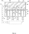
- Fig. 2 illustrates example heat transfer devices 100 in which the barrier element 700 is in the closed configuration.
- Fig. 2 illustrates heat 104 flowing from heat source 102 to the coolant 300 during operation of the heat transfer devices 100.
- Heat 104 may flow from the heat source 102 and through the heat transfer components 500, a storage housing 202, a cooling housing 402, a storage heat transfer component 516, another heat transfer means (such as a radiation and/or other environmental conductors located proximate to the heat transfer devices 100 and/or heat source 102), or a combination thereof.
- Fig. 2 further shows the heat 104 flowing into the coolant 300.
- the heat transfer device 100 draws heat 104 away from the heat source 102 and stores heat 104 in the coolant 300.
- Such heat transfer may (or may not) be described as Forced convection, where buoyancy force is g ⁇ L, where L is a length scale, and ⁇ is a temperature scale, as described by DJT's Physical Fluid Dynamics 2nd edition Ch. 14 , Convection.
- the heat transfer devices 100 also include a heat distribution element 302 located within the enclosed storage volume 206, and which is configured to distribute heat 104 across the coolant 300.
- the heat distribution element 302 may include an aluminum foam, or other conductive mesh through which heat 104 can be distributed across and into the coolant 300.
- Fig. 3 illustrates example heat transfer devices 100 in which the barrier element 700 is in the open configuration.
- Fig. 3 shows a coolant path 304 along which the coolant 300 flows from the enclosed storage volume 206, through the fluid passage 600, and into cooling chamber 400.
- the pressure of the coolant 300 in the storage chamber 200 may drive the flow of coolant 300 through the fluid passage 600 and into the cooling chamber 400. That is, because the pressure of the coolant 300 in the storage chamber 200 is greater than the pressure in the cooling chamber 400, the coolant 300 may passively flow from the storage chamber 200 to the cooling chamber 400.
- the temperature of the coolant 300 will drop as the coolant 300 expands into the cooling chamber 400.
- the temperature of the coolant 300 also may be reduced by an expansion device (e.g., a thermal expansion valve, an expansion valve, an expansion element, capillary tube, etc.) in the fluid passage 600.
- an expansion device e.g., a thermal expansion valve, an expansion valve, an expansion element, capillary tube, etc.
- Fig. 3 illustrates the coolant flowing along one or more coolant flow paths 520 and to an exit interface 412.
- Fig. 3 also shows heat 104 flowing from the heat transfer components 500 and into the coolant 300.
- an exhaustion region such as the environment, an overflow tank 108, or other location outside of the cooling chamber 400.
- the passive flow of the coolant 300 causes the heat transfer device 100 to both draw heat 104 away from the heat source 102 and exhaust the heat 104 into an exhaustion region.
- the cooling chamber 400 includes one or more test ports.
- test ports may be used for functions including but not limited to Non-Destructive Testing (NDT) and/or Non-Destructive Inspection (NDI), a leak test, a flow test, testing of safety/reliability/mission-reliability/repeatability, injection of fluid or some other substance into the cooling chamber, drawing of a vacuum and/or altering the pressure in the cooling chamber, cleaning of the chamber including removal of grit/FOD and/or unsintered AM powder, and/or an additional exhaust port during operation of the device; though other methods and/or devices may achieve these functions including the single exhaust port in contribution with or disjoint from the test ports; and such test ports may be permanently or temporarily sealed.
- NDT Non-Destructive Testing
- NDI Non-Destructive Inspection
- the coolant 300 will continue to passively flow out of the storage chamber 200 until the pressure of the coolant 300 in the storage chamber 200 and the pressure in the cooling chamber 400 reaches equilibrium. Additionally, the mass flow rate of the coolant 300 out of the storage chamber 200 will be relationally dependent upon the pressure difference between the pressure of the coolant 300 in the enclosed storage volume and the pressure in the cooling chamber 400. This will cause the mass flow rate of the coolant 300 to reduce as the storage chamber 200 and the pressure in the cooling chamber 400 equilibrates.
- the transfer of heat 104 from the heat source 102 to the coolant 300 depicted in Fig. 2 continues to occur while the barrier element 700 is in the open configuration.
- the heat 104 which continues to flow into the coolant 300 in the storage chamber 200 increases the pressure of the coolant 300 in the storage chamber 200, thus driving a continued flow of coolant 300 into the cooling chamber 400.
- the storage chamber 200 may include a storage housing 202.
- An internal surface 204 of the storage housing 202 defines an enclosed storage volume 206.
- the storage housing 202 and the enclosed storage volume 206 may take various suitable shapes depending on application and/or volumetric requirements for specific applications.
- the storage housing 202 and/or the enclosed storage volume may be cylindrical, a rectangular prism, or any other shape.
- a coolant 300 is stored within the enclosed storage volume 206.
- the coolant 300 may include any substance capable of efficiently absorbing heat.
- the coolant 300 is able to flow from the storage chamber 200 to the cooling chamber 400 through the fluid passage 600 when the barrier element 700 is in a fully and/or partially open configuration, as schematically represented in Fig. 3 .
- the coolant 300 may be a liquid at normal operating conditions of the heat transfer devices 100.
- Normal operating conditions of the heat transfer devices 100 include a range of potential conditions (e.g., temperature, pressure, humidity, etc.) that are likely to exist during the course of an undertaking for which a particular heat transfer device 100 is designed. In this way, depending on the purposes of individual heat transfer devices, different coolants 300 may be selected that have characteristics that align with the normal operating conditions of the corresponding heat transfer device 100.
- the coolant 300 may be selected for its ability to remain in a stable condition for long periods of time.
- periods of time include 10 ⁇ -18, 10 ⁇ -15, 10 ⁇ -9, 10 ⁇ 0, 10 ⁇ 1, 10 ⁇ 2, 10 ⁇ 3, 10 ⁇ 4, 10 ⁇ 5, 10 ⁇ 6, 10 ⁇ 7, 10 ⁇ 8, at least 10 ⁇ -18, at least 10 ⁇ -15, at least 10 ⁇ -9, at least 10 ⁇ 0, at least 10 ⁇ 1, at least 10 ⁇ 5, at least 10 ⁇ 10, less than 10 ⁇ -18, less than 10 ⁇ -15, less than 10 ⁇ -9, less than 10 ⁇ -0, less than 10 ⁇ 1, less than 10 ⁇ 5, and/or less than 10 ⁇ 10, seconds, minutes, hours days, weeks, months, years, decades, or other units of time.
- the coolant may need to remain stable in the storage chamber for years before the electronic component is activated and/or otherwise generates heat.
- the coolant 300 may be such that a boiling point temperature is greater than a range of operating temperatures of the heat transfer device, and/or a freezing point temperature is less than a range of operating temperatures of the heat transfer device. This may allow the heat transfer device 100 to remain dormant for long periods of time without the coolant breaking down, losing/altering its functional properties, or damaging the heat transfer device 100.
- the coolant 300 may partially and/or entirely comprise methane.
- the coolant 300 may include component elements that improve the stability of the coolant 300.
- the coolant may include a component element that is itself a fire retardant, or which, when combined with other components of the coolant 300 prevent the coolant 300 from igniting.
- the coolant 300 may include component elements that improve and or provide a voltage-carrying capability of the coolant 300.
- the coolant may optionally include a mixture of water and manganese sulfate.
- the heat transfer devices 100 may include storage heat transfer component 516.
- the storage heat transfer component 516 may be a component distinct from the heat transfer components 500, and which is configured to permit heat to transfer between the heat source 102 without passing through the cooling chamber 400.
- the fluid passage 600 is configured to allow coolant 300 to flow from the storage chamber 200 to the cooling chamber 400.
- the fluid passage 600 is configured to expand the coolant 300 as it flows through the fluid passage.
- coolant 300 may flow into the fluid passage 600 at an initial pressure and may flow out of the fluid passage 600 at an expanded pressure that is lower than the initial pressure.
- the reduction of the pressure of the coolant 300 may be a result of the coolant 300 moving from the enclosed storage volume 206 such that it is housed within an increased volume (i.e., from the enclosed storage volume 206 to an area including both the enclosed storage volume 206 and the enclosed cooling volume 406), may be a result of the coolant 300 passing through an expansion device (e.g., a thermal expansion valve, an expansion valve, an expansion element, capillary tube, etc.) as the coolant 300 moves through the fluid passage 600, or a combination thereof.
- the fluid passage 600 may include an expansion valve 602 coupled to the storage chamber 200 and/or the cooling chamber 400.
- the coolant 300 flows from the storage chamber and into such an expansion valve 602 at an initial pressure and flows out of the expansion valve 602 and toward the cooling chamber 400 at an expanded pressure that is less than the initial pressure.
- the expansion valve 602 and/or another component of the fluid passage 600 may cause the coolant 300 to transition from a liquid state to a gaseous state.
- coolant 300 is stored in the enclosed storage volume 206 in a liquid state but is a gas when the coolant 300 flows into the cooling chamber 400 via the fluid passage 600.
- the fluid passage 600 may include a fluid chamber 640.
- the fluid chamber 640 may be an enclosed volume that coolant enters via the barrier element 700 when the barrier element 700 is in an open configuration. Coolant 300 may exit the fluid chamber 640 and enter the enclosed cooling volume 406. Additionally, in some examples, the fluid passage 600 may be a shared fluid passage 660 into which coolant 300 flows when any individual barrier element 700 of a set of more than one barrier element 700 are in an open configuration.
- heat transfer device 100 also includes a cooling chamber 400 that is located adjacent to the storage chamber 200.
- Cooling chamber 400 includes a cooling housing 402 that has an internal surface 404 which defines an enclosed cooling volume 406.
- One or more of the cooling housing 402 and/or the enclosed cooling volume 406 may be cylindrical, a rectangular prism, or any other shape.
- the shape of the enclosed cooling volume 406 may be the same shape as the enclosed storage volume 206 or may be a different shape.
- the heat transfer device 100 may further include a through hole 408 that is located at an interface between the fluid passage 600 and the enclosed cooling volume 406.
- the through hole 408 is defined by the storage housing 202 and/or cooling housing 402 and is configured to allow coolant 300 to flow from the fluid passage 600 to the enclosed cooling volume 406.
- the through hole 408 may be located at a central region of the cooling chamber 400.
- the through hole 408 may be positioned at any other location of the cooling chamber 400, such as along a side region of the cooling chamber 400.
- the heat transfer device 100 may include two or more through holes 408 through which coolant can pass from the fluid passage 600 to the enclosed cooling volume 406. In such examples, the two or more through-holes can be radially symmetric or radially asymmetric.
- the heat transfer device 100 includes three or more through holes, all may be symmetric, asymmetric, or a sub-set may be symmetric. Additionally, individual through holes do not have to be circular, and they may take on any shape, including a square, a trapezoid, etc.
- the heat transfer device 100 also includes an adapter 410 positioned in or adjacent to a through hole 408 that is configured to convert the shape of the corresponding through hole 408. For example, an adapter 410 may be placed in a circular through hole 408 to convert it to a trapezoidal through hole 408.
- the cooling chamber 400 also may include one or more exit interfaces 412 configured to allow the coolant 300 to flow out of the enclosed cooling volume 406.
- An exit interface 412 may correspond to a hole defined by the cooling housing 402. The coolant may flow out of the enclosed cooling volume 406 and into an exhaustion region, such as the environment 106, an overflow tank 108, or another location outside of the enclosed cooling volume 406.
- the exit interface 412 may allow coolant 300 to flow from the enclosed cooling volume 406 to a chimney 414 (see for example figures 8, 9 or 13 )) that allows the coolant to flow through or adjacent to the enclosed storage volume 206, and/or one or more other components of the heat transfer device 100.
- the cooling chamber 400 may include a sewer structure configured to direct the flow of coolant 300 toward and/or through the enclosed cooling volume 406.
- the sewer structure may also direct the flow of coolant 300 out of the enclosed cooling volume 406, and/or the heat transfer device 100.
- Heat transfer device 100 also includes one or more heat transfer components 500 that are configured to allow heat to transfer between the heat source 102 and the enclosed cooling volume 406.
- Individual heat transfer components 500 may include a heating end 501 located proximate to the heat source 102 and a cooling end 503 located within the enclosed cooling volume 406 (shown in figure 1 ).
- the heating end 501 may be operatively coupled to the heat source 102 such that heat 104 generated by the heating source flows to the heating end 501.
- the heat transfer components 500 may include a conductive portion 518 that extends into the enclosed storage volume 206.
- a barrier 900 between the enclosed cooling volume 406 and the enclosed storage volume 206 may correspond to and/or optionally include a heat transfer component 500, such as a conductive film, coating, layer and/or other barrier structure that partially or completely separates the enclosed cooling volume 406 from the enclosed storage volume 206.
- a barrier 900 may include one or more of a braze foil 902 (shown in figure 15 ), a parting sheet with fin array, and/or other conductive components that are configured to allow heat to transfer into the enclosed storage volume 206 and/or evenly distribute the heat across the barrier.
- the one or more heat transfer components 500 may include pins 506, vanes 508, rods 510, fins, and/or other structures that are configured to allow heat to transfer between the heat source 102 and the enclosed cooling volume 406.
- the heat transfer components 500 may include a plurality of sponge rods distributed within the enclosed cooling volume.
- Heat transfer device 100 may include a number of pins 506, rods 510, or a combination thereof arranged within the enclosed cooling volume 406 in a matrix array, an off-set matrix array, a spiral array, or any other distributed pattern (shown in figure 1 ).
- the size of individual pins 506, vanes 508, rods 510, fins, and/or other heat transfer components may be constant or may vary in size.
- heat transfer components 500 located near through hole 408 may be smaller (i.e., have a smaller radius, surface area, height, etc.) than heat transfer components 500 located further from the through hole 408.
- the cross-sectional shape of pins 506 and/or rods 510 may be circular, ovoid, polygonal, Vesica Piscis, or another shape.
- some or all of the cooling housing 402 may comprise a conductive material that distributes heat from the heat source 102 to the enclosed cooling volume 406.
- a side and/or portion 416 of the cooling housing 402 may comprise a conductive material that distributes heat from the heat source 102 to the enclosed cooling volume 406, the internal surface 404, and or one or more pins 506, vanes 508, rods 510, fins, and/or other structural components of the heat transfer components 500.
- the side and/or portion 416 of the cooling housing 402 may be a flat side/portion, or may have raised, curved, or other irregularities 418 that increase the surface area for heat transfer between the side and/or portion 416 and the enclosed cooling volume 406.
- the heat transfer device 100 may further include one or more vanes or other structures configured to guide the flow of coolant 300 through the enclosed cooling volume 406 from the through hole 408 to the exit interface 412.
- the vanes or other structures may optionally include cutouts 514 that are configured to allow the coolant to flow through the vanes.
- the cutouts 514 also may be described as voids, holes, openings, passages, passageways, etc.
- the cutouts 514 may be circular, ovoid, polygonal, diamond, or another shape.
- the cutouts may alter the wall shear ⁇ w , as defined by Shapiro's The Dynamics and Thermodynamics of Compressible Fluid Flow Ch. 27, Volume 2 .
- the one or more vanes or other structures may be heat transfer components 500 configured to allow heat to transfer from the heat source 102 to the enclosed cooling volume 406.
- the heat transfer components 500 may include vanes 508, fins, or other structures that are positioned to guide the flow of coolant 300 along a coolant flow path 520.
- individual vanes 508, fins, or other structures may have a constant width, a varying width, a constant height, a varying height, be perpendicular to an associated surface of the cooling housing 402, have a camber angle between the individual vane 508 and the associated surface of the cooling housing 402, or a combination thereof.
- the coolant flow path 520 may include one or more switchbacks 522. In some examples, there may be two or more coolant flow paths 520 through which coolant 300 can flow from a through hole 408 to an exit interface 412. For example, where the through hole 408 is centrally located in the enclosed cooling volume 406, the vanes or other structures may define a plurality of coolant flow paths 520 that lead radially outward from the through hole 408.
- the heat transfer device 100 also includes a barrier element 700 that is configured to control the flow of coolant 300 from the storage chamber 200 to the cooling chamber 400.
- the barrier element 700 is configured to have a closed configuration in which the barrier element 700 restricts the coolant 300 from flowing from the storage chamber 200, and an open configuration in which the barrier element 700 allows the coolant 300 in the storage chamber 200 to flow through the fluid passage 600 and into the cooling chamber 400.
- Example barrier elements 700 may include, but are not limited to, any combinations of burst discs, permeable membranes, plungers, release valves, pressure release valves, check valves, pyrotechnic valves, solenoid valves, ball and spring valves, etc.
- the barrier element 700 is configured to reconfigure from the closed configuration to the open configuration in response to a trigger condition.
- the trigger condition may correspond to the coolant 300 housed in the enclosed storage volume 206 reaching a certain temperature, the current pressure (i.e., the pressure at a corresponding time, a present time, or current time) of the coolant 300 housed in the enclosed storage volume 206 reaching a certain pressure level, or a combination thereof.
- the barrier element 700 is configured to passively transition from the closed configuration to the open configuration. That is, the barrier element 700 may not require a signal or other stimulus from outside of the heat transfer device 100 to transition from the closed configuration to the open configuration.
- the barrier element 700 may be configured to passively transition from the closed configuration to the open configuration in response to operating conditions of the heat transfer device 100 (e.g., conditions of the coolant 300 in the enclosed storage volume 206, etc.).
- the barrier element 700 may include a burst disc 702 that forms a barrier that restricts the coolant 300 from flowing from the enclosed storage volume 206, and which is configured to rupture when a pressure that the coolant 300 applies to the burst disc 702 exceeds a certain pressure level.
- one or more of the characteristics of the burst disc 702 may be designed so that the burst disc 702 ruptures when the coolant 300 reaches a set temperature. That is, when characteristics of the heat transfer device 100 are so designed, when the coolant 300 reaches the set temperature the coolant 300 will exert an amount of pressure on the burst disc 702 that is sufficient to rupture the burst disc 702.
- the barrier element 700 may include a membrane 704 through which coolant 300 can only pass through when certain conditions are met.
- the membrane 704 may be configured to restrict the coolant 300 from flowing from the enclosed storage volume 206 when the pressure exerted by the coolant 300 onto the membrane 704 is below a threshold pressure, and may be configured to allow the coolant 300 to flow across the membrane 704 when the pressure that the coolant 300 applies to the membrane 704 exceeds the pressure threshold.
- the barrier element 700 may include at least one plunger device 706 that is configured to create a passage through which the coolant 300 is able to flow from the enclosed storage volume 206 to the fluid passage 600.
- the plunger device 706 may include a puncturing needle 708 having a puncturing end 710, such as a needle tip and/or a hollow tip.
- the plunger device 706 includes a driving mechanism that causes the puncturing end 710 to rupture a barrier or burst disc 702 or other barrier responsive to the trigger condition.
- the plunger device 706 may include a pressure tab that is configured to burst when a pressure exerted on the pressure tab exceeds a threshold value, or when the temperature of the pressure tab exceeds a threshold value.
- the plunger device 706 may optionally include a restraining element 740 that prevents the plunger device 706 from moving to a neutral position, wherein the plunger device 706 moving to the neutral position includes creating the passage through which the coolant 300 is able to flow from the enclosed storage volume 206 to the fluid passage 600.
- the plunger device 706 may include a spring, piston, or other dynamic mechanism that biases the plunger device 706 to the neutral position.
- the restraining element 740 may be configured to restrain the plunger device 706 in a non-neutral position until the occurrence of a trigger event.
- the restraining element 740 may comprise a material (e.g., wax, lead, etc.) that melts at a threshold temperature, where once melted, the plunger device 706 is allowed to move to the neutral position.
- the plunger device 706 also may be configured to plug the passage in response to a close condition, such as a closing pressure being applied to the plunger device, the plunger device 706 reaching a closing temperature, etc.
- the heat transfer device 100 also may include a closed circuit 742 that is configured to control and/or initiate the transition of the barrier element 700 from the closed configuration to the open configuration.
- the closed circuit 742 may include a sensor 744, such as pressure sensor (e.g., strain gauge), temperature sensor (e.g., thermocouple), or other sensor that is configured to detect the occurrence of a trigger condition.
- the closed circuit 742 may include a thermocouple that is configured to produce a voltage sufficient to cause the barrier element 700 to transition between the closed configuration and the open configuration.
- heat transfer device 100 also may optionally include one or more additional storage chambers 250, additional coolants 350 housed within the additional storage chambers 250, additional fluid passages 650 between the additional storage chambers 250 and the cooling chamber 400, and additional barrier elements 750.
- the heat transfer device 100 may include a plurality of additional storage chambers 250, where each individual additional storage chamber 250 stores additional coolant 350.
- individual additional barrier elements 750 may be configured to have a closed configuration in which the additional barrier element 750 restricts the additional coolant 350 from flowing from the additional storage chamber 250, and an open configuration in which the additional barrier element 750 allows the additional coolant 350 in the additional storage chamber 250 to flow through the additional fluid passage 650 and into the cooling chamber 400.
- individual additional barrier elements 750 are configured to reconfigure from the closed configuration to the open configuration in response to an additional trigger condition(s) that are different from the trigger conditions for barrier element 700.
- the additional trigger condition for an additional barrier element 750 may correspond to one or both of (i) the additional coolant 350 housed within the additional storage chamber 250 reaching an additional trigger temperature, and (ii) the initial pressure of the additional coolant 350 housed within the additional storage chamber 250 reaching an additional trigger pressure.
- the additional fluid passage 650 may be configured to expand the additional coolant 350 from an initial pressure to an expanded pressure as the additional coolant 350 flows from the additional storage chamber 250 through the additional fluid passage 650 and to the cooling chamber 400 responsive to the additional barrier element 750 reconfiguring from the closed configuration to the open configuration.
- the fluid passage 600 may be a shared fluid passage 660, and the additional barrier element 750 may be configured to allow the additional coolant 350 to flow into the shared fluid passage 660 (shown, for example, in figures 6 and 9 ).
- At least one of the component elements of the heat transfer device 100 may be constructed using additive manufacturing.
- one or more heat transfer components 500 may be partially or completely constructed and/or otherwise added to the enclosed cooling volume 406 using additive manufacturing.
- Example additive manufacturing methods and printers include, but are not limited to, VAT photopolymerization, powder bed fusion, binder jetting, material jetting, sheet lamination, material extrusion, directed energy deposition, directed metal laser sintering, direct metal printing, electron beam additive manufacturing, electron beam melting, electron beam powder bed, fused deposition modeling, indirect power bed, laser cladding technology, laser deposition technology, laser deposition welding, laser deposition welding with integrated milling, laser engineering net shape, laser freeform manufacturing technology, laser metal deposition-powder, laser metal deposition-wire, laser powder bed, laser puddle deposition, laser repair technology, powder directed energy deposition, stereolithography, selective laser melting, selective laser sintering, small puddle deposition, as well as hybrid processes thereof.
- powder may be formed as collected
- Exemplary additive manufacturing materials include metals such as steel, stainless steel, titanium, copper, aluminum, nickel alloys, and alloys thereof, including but not limited to IN625, IN718, Ti-6AI-4V, Al-Si-10Mg, SS316, Monel, Monel K500, Copper, Ti-5553, Ti-6AI-6V-2Sn, Ti-6242, Maraging Steel MSI 18, Mar 300, 316L, 17-4, 15-4, Cobalt Chrome SP2, Ti-6AI-4V ELI, Nickel Alloy HX, gold (au), silver (ag), as well as plastics/polymers/elastomers including Acrylonitile Butadiene Styrene (ABS), Polylactic acid (PLA), Polyvinyl alcohol, and Polycarbonate, and others including ULTEM, Kel-F, Kevlar, Nylon, and Carbon Composite, as well as thermoplastics such as Polyamide (PA), Polyphenylene Sulfide (PPS), Polyether Ether Ketone (PEEK), Poly-Ether-K
- the heat transfer device disclosed herein may be partially or completely formed of, or may otherwise include Functionally Gradient Material (FGM).
- FGM Functionally Gradient Material
- a component element of the fluid passage 600 such as an expansion valve or other type of valve, may be formed of a FGM that comprises a blend from Ti-6AI-4V to Al-Si-10Mg.
- the structure disclosed herein may be formed by altering the blending of deposited additively manufactured material such that Functionally Gradient Material (FGM) properties may be achieved, including varying the Coefficient of Thermal Expansion (CTE). Such varying may be useful for passive actuation of puncturing devices.
- FGM Functionally Gradient Material
- support materials may be used, such as support materials for plastics like PVA or support materials for metallic elements, including water-soluble crystals and other melt-aways, including, but not limited to Cu, Ag, Al, Sb, Zn and Sn, as well as other alloys such as solder and low melting point Ag alloy solder (Ag-Sn-Pb, Ag-Pb, Ag-Sn, Ag-Sn-Cu, Ag-Cd-Zn, Ag-Cd); polyethylene, polyamide, polyimide, polypropylene, PMMA, polyether sulfone, thermoplastic polyester, copolymer or polyhexafluroropropylene and polytetrafluoroethylene, polyfluorovinylidene, and other organic composite photoresist materials, including but not limited to dry film type resists such as those discussed in U.S. Patent No. 5,805,971 .
- the device also may be constructed with non-thermoplastic materials, including epoxies
- One or more parts of the structure also may be formed from plastics, including but not limited to Nylon, acrylonitrile butadiene styrene, polyactic acid, polyetherimide (ULTEM ® ), Carbon fiber, para-aramid synthetic fibers (KEVLAR ® ), polychlorotrifluoroethylene, polytetrafluoroethylene (TEFLON TM ), and polyethylene terephthalate.
- plastics including but not limited to Nylon, acrylonitrile butadiene styrene, polyactic acid, polyetherimide (ULTEM ® ), Carbon fiber, para-aramid synthetic fibers (KEVLAR ® ), polychlorotrifluoroethylene, polytetrafluoroethylene (TEFLON TM ), and polyethylene terephthalate.
- the structure may be constructed of flexible material for purposes of resiliency to high-vibration regimes, flexure in aeroelastic applications.
- Figs. 4-14 illustrative non-exclusive examples of storage chambers 200 and cooling chambers 400 according to the present disclosure are illustrated.
- the reference numerals from the schematic illustrations of Figs. 1-3 are used to designate corresponding parts of the examples of Figs. 4-14 ; however, the examples of Figs. 4-14 are non-exclusive and do not limit heat transfer devices 100 to the illustrated examples of Figs. 4-14 . That is, heat transfer devices 100 according to the present disclosure are not limited to the specific examples of the example storage chambers 200 and cooling chambers 400 illustrated in Figs. 4-14 , and heat transfer devices 100 may incorporate any number of the various aspects, configurations, characteristics, properties, etc.
- Figs. 4-6 illustrate example storage chambers for a heat transfer device 100 according to the present disclosure, in which the barrier device comprises a burst disc or membrane.
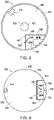
- Fig. 4 illustrates an example cylindrical storage chamber 200 in which the barrier element 700 is a burst disc or membrane centrally located within the storage chamber 200.
- the barrier element 700 ruptures and/or otherwise allows the coolant 300 to flow into an associated enclosed cooling volume via a fluid passage 600.
- Fig. 5 illustrates an example storage chamber 200 having a polygonal prism shape, and in which the barrier element 700 is a burst disc or membrane that is not centrally located within the storage chamber 200.
- the barrier element 700 is a burst disc or membrane that is not centrally located within the storage chamber 200.
- coolant 300 stored in the enclosed storage volume 206 flows into the fluid passage 600.
- the coolant 300 may then flow into an associated enclosed cooling volume 406 by passing through a through hole 408.
- Fig. 5 further illustrates fluid chamber 640 as including a catch 642 that is configured to physically prevent debris from traveling through the through hole 408 with the flow of coolant 300.
- Fig. 6 illustrates an example apparatus that includes a storage chamber 200 and multiple additional storage chambers 250.
- Fig. 6 illustrates an apparatus that includes an enclosed storage volume 206 that stores coolant 300, and multiple additional storage chambers 250 that store additional coolant 350.
- Fig. 6 also shows the apparatus including a barrier element 700 and multiple additional barrier elements 750.
- Fig. 6 also shows multiple barrier elements 760 that, when in an open configuration, each allow additional coolant to flow into a shared fluid passage 660 that comprises a fluid chamber 640.
- Figs. 7-9 illustrate example storage chambers for a heat transfer device 100 according to the present disclosure, in which the barrier device comprises a plunger device.
- Fig. 7 illustrates an example cylindrical storage chamber 200 in which the barrier element 700 includes a plunger device 706.
- the plunger device 706 actuates the puncturing needle 708 so that the puncturing end 710 creates a rupture in a burst disc 702 or other barrier.
- Coolant 300 is then able to flow through the rupture and into the fluid passage 600.
- the coolant 300 may then pass into the enclosed cooling volume 406 via the through hole 408.
- the plunger device 706 optionally may include a pressure tab that is configured to burst when a pressure exerted on the pressure tab exceeds a threshold value, or when the temperature of the pressure tab exceeds a threshold value.
- the plunger device 706 may include a restraining element 740 that prevents the plunger device 706 from moving to a neutral position, wherein the plunger device 706 moving to the neutral position includes creating the passage through which the coolant 300 is able to flow from the enclosed storage volume 206 to the fluid passage 600.
- Fig. 8 illustrates an example storage chamber 200 in which the barrier element 700 includes a plunger device 706, and including a chimney 414.
- the example storage chamber 200 shown in Fig. 8 also includes an opening 920 defined by the storage housing 202.
- the opening 920 may allow a line of sight through the storage chamber 200.
- the storage chamber 200 and the cooling chamber 400 may include opening 920 so that a line of sight exists through the storage chamber 200 and cooling chamber 400 such that at least a portion of the heat source 102 and/or other surface to which the heat transfer device 100 is attached is made visible.
- Fig. 8 also illustrates fluid passage 600 including multiple through holes 408, and a chimney 414 that allows the coolant 300 to flow from the enclosed cooling volume and through the enclosed storage volume 206 and/or one or more other components of the heat transfer device 100.
- Fig. 9 illustrates an example apparatus that includes a storage chamber 200 and additional storage chambers 250.
- Fig. 9 illustrates an apparatus that includes multiple barrier elements 700 (i.e., plunger devices 706) that each, when in an open configuration, allow coolant 300 or 350 to flow into a shared fluid passage 660 and through hole 408.
- Fig. 9 also illustrates a chimney 414 that allows the coolant 300 or 350 to flow from the enclosed cooling volume and through the enclosed storage volume 206 and/or one or more other components of the heat transfer device 100.
- Figs. 10-14 illustrate example cooling chambers for a heat transfer device 100 according to the present disclosure.
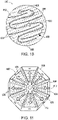
- Fig. 10 illustrates an example cylindrical cooling chamber 400 with a single coolant flow path 520 and multiple switchbacks 522.
- Coolant 300 may enter the enclosed cooling volume 406 via the through hole 408 and may be directed by vanes 508 to flow along the coolant flow path 520.
- Fig. 10 also illustrates an offset matrix array of pins 506.
- individual vanes 508 may have a constant width, a varying width, a constant height, a varying height, may be perpendicular to an associated surface of the cooling housing 402, may have a camber angle between the individual vane 508 and the associated surface of the cooling housing 402, or a combination thereof.
- vanes 508 and pins 506 may be configured to allow heat to transfer from a heat source 102 and into the coolant 300 as the coolant 300 flows along the coolant flow path 520.
- Fig. 10 also illustrates an exit interface 412 through which the coolant 300, as well as any heat absorbed by the coolant during its traversal of the coolant flow path 520, may flow out of the enclosed cooling volume 406.
- Fig. 11 illustrates an example cooling chamber 400 with multiple coolant flow paths extending radially outward from a through hole. Coolant may enter the enclosed cooling volume via the through hole 408 and may flow radially outward along one of the coolant flow paths 520 defined by vanes 508.
- Fig. 11 also illustrates a plurality of heat transfer components 500 arranged in a matrix array, configured to allow heat to transfer from a heat source 102 and into the coolant 300 as the coolant 300 flows along the coolant flow paths 520.
- Fig. 11 also illustrates multiple exit interfaces 412 through which the coolant 300, as well as any heat absorbed by the coolant during its traversal of the coolant flow path 520, may flow out of the enclosed cooling volume 406.
- Fig. 12 illustrates an example cylindrical cooling chamber 400 with multiple coolant flow paths 520 having switchbacks 522. Coolant may enter the enclosed cooling volume via the multiple through holes 408 and may flow along one of the coolant flow paths 520 defined by the vanes 508. Fig. 12 further shows a portion of the cooling housing 402 as comprising a conductive material that distributes heat from the heat source 102 to the coolant 300 as it flows along the coolant flow paths 520. Fig. 12 also illustrates multiple exit interfaces 412 through which the coolant 300, as well as any heat absorbed by the coolant during its traversal of the coolant flow path 520, may flow out of the enclosed cooling volume 406.
- Fig. 13 illustrates an example cylindrical cooling chamber 400 with two coolant flow paths 520 and an opening 920. Coolant may enter the enclosed cooling volume via the multiple through holes 408 and may flow along one of the two coolant flow paths 520 to chimney 414.
- Fig. 13 also illustrates a plurality of heat transfer components 500 arranged in a matrix array.
- Fig. 13 also shows heat transfer components that are located proximate to the through holes 408 are smaller than (e.g., have a reduced radius, height, surface area, etc.) the heat transfer components that are proximate the chimney 414.
- the example cooling chamber 400 shown in Fig. 13 also includes an opening 920 defined in by the cooling housing 402 that allows a line of sight through the cooling chamber 400.
- Fig. 14 illustrates an example cooling chamber 400 with multiple curved coolant flow paths extending radially outward from a through hole.
- Coolant 300 may enter the enclosed cooling volume via the through hole 408 and may flow radially outward along one of the curved coolant flow paths 520 defined by curved vanes 508.
- the coolant 300 enters the enclosed cooling volume at a central distribution location that is designed to allow the coolant 300 to flow through each of the multiple curved coolant flow paths.
- the coolant 300 is pushed outward from the central distribution location and into each of the multiple curved coolant flow paths.
- Fig. 14 illustrates an example cooling chamber 400 with multiple curved coolant flow paths extending radially outward from a through hole.
- Coolant 300 may enter the enclosed cooling volume via the through hole 408 and may flow radially outward along one of the curved coolant flow paths 520 defined by curved vanes 508.
- the coolant 300 enters the enclosed cooling volume at a central distribution location that is designed to allow the coolant 300 to
- Fig. 14 the coolant flow paths 520 defined by the vanes 508 may expand the farther they are from the through hole 408.
- Fig. 14 also illustrates a plurality of heat transfer components 500 (i.e., pins 506) arranged in a matrix array, configured to allow heat to transfer from a heat source 102 and into the coolant 300 as the coolant 300 flows along the coolant flow paths 520.
- Fig. 14 also illustrates multiple exit interfaces 412 through which the coolant 300, as well as any heat absorbed by the coolant during its traversal of the coolant flow path 520, may flow out of the enclosed cooling volume 406.
- Fig. 14 illustrates cutouts 514 in vanes 508.
- the cutouts 514 are illustrated as circular cutouts 514 that are configured to allow the coolant 300 to flow through the vanes 508.
- the cutouts 514 may be otherwise distributed, sized, and/or shaped including diamond, Vesica Pisces and/or other shapes.
- the cutouts 514 may be distributed, sized, and/or shaped within the vanes 508 so that the flow rate of coolant 300 through each cutout 514 is constant for all cutouts 514.
- one or more of vanes 508 may be hollow and/or include internal pathways. In this way, the coolant 300 may travel internally within the hollow vanes 508, internal pathways, and/or through the cutouts 514 as the coolant 300 travels outwardly from the center of the cooling chamber 400.
- Fig. 15 is an exploded view of an example heat transfer device according to the present disclosure.
- Fig. 15 illustrates component elements of a storage chamber 200 partially defined by storage housing 202 and configured to store a coolant and a heat distribution element 302 configured to distribute heat across the coolant 300.
- Fig. 15 also illustrates a barrier 900 between the storage chamber 200 and the cooling chamber 400 that comprises a heat transfer component 500, such as a conductive film, coating, layer and/or other barrier structure that partially or completely separates the enclosed cooling volume 406 from the enclosed storage volume.
- a heat transfer component 500 such as a conductive film, coating, layer and/or other barrier structure that partially or completely separates the enclosed cooling volume 406 from the enclosed storage volume.
- barrier 900 includes one or more of a braze foil 902, a parting sheet with fin array, and/or other conductive components that are configured to allow heat to transfer into the cooling chamber 400 and/or evenly distribute the heat across the barrier 900.
- the storage housing 202 and/or barrier 900 may include one or more seals, such as a Gibbous O-ring Layering seal that prevents the coolant from leaking from the enclosed storage chamber 200.
- Fig. 15 also shows the example heat transfer device as including a barrier element 700 and fluid passage 600. In its exploded view, Fig. 15 also shows the example heat transfer device as including the example cooling chamber 400 depicted in Fig. 14 .
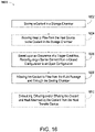
- Fig. 16 schematically provides a flowchart that represents illustrative, non-exclusive examples of methods according to the present disclosure.
- some steps are illustrated in dashed boxes indicating that such steps may be optional or may correspond to an optional version of a method according to the present disclosure. That said, all methods according to the present disclosure are required to include the steps illustrated in solid boxes.
- the methods and steps illustrated in Fig. 16 are not limiting and other methods and steps are within the scope of the present disclosure, including methods having greater than or fewer than the number of steps illustrated, as understood from the discussions herein.
- Fig. 16 is a flowchart depicting methods 1600, according to the present disclosure, for cooling a heat source using a heat transfer device 100.
- Methods 1600 include storing a coolant (e.g., coolant 300) in a storage chamber (e.g., storage chamber 200) at 1602.
- the storage chamber may include an enclosed volume (e.g., enclosed storage volume 206) that is defined by a housing of the storage chamber.
- the coolant may include any substance capable of efficiently absorbing heat, and which within normal operating conditions is able to flow from the storage chamber to the cooling chamber through the fluid passage.
- the coolant 300 may be a liquid at normal operating conditions of the heat transfer device 100.
- Methods 1600 include allowing heat to transfer from the heat source (e.g., heat source 102) to the coolant stored in the storage chamber at 1604.
- heat may transfer from the heat source to the coolant through components configured to facilitate heat transfer (e.g., the heat transfer components 500, the storage housing 202, the cooling housing 402, the storage heat transfer component 516, etc.) another heat transfer means, such as a radiation and/or other environmental conductors located proximate to the heat transfer device 100 and/or heat source, or a combination thereof.
- a barrier element reconfigures from (i) a closed configuration in which the barrier element is configured to restrict the coolant from flowing from the storage chamber through the fluid passage, and to (ii) an open configuration in which the barrier element is configured to allow the coolant in the storage chamber to flow from the storage chamber through the fluid passage.
- the barrier element may reconfigure from the closed configuration to an open configuration based upon an occurrence of a trigger condition.
- the trigger condition may include at least one of the coolants reaching a trigger temperature, and/or the coolant reaching a trigger pressure.
- the barrier element may passively reconfigure from the closed configuration to an open configuration in response to the trigger condition.
- the barrier element may include one or more of a burst disc, a membrane, a plunger device, a release valve, a pressure release valve, a check valve, a pyrotechnic valve, a solenoid valve, a ball and spring valve, etc., that passively transition from the closed configuration to the open configuration responsive to the trigger condition.
- the coolant is allowed to flow from the fluid passage and through the cooling chamber, wherein while the coolant flows through the cooling chamber heat is transferred from the heat source and to the coolant via one or more heat transfer components.
- the coolant may flow into the cooling chamber via the fluid chamber.
- the coolant flows from the storage chamber and into the fluid passage at an initial pressure and flows out of the fluid passage toward a cooling chamber at a final pressure that is less than the initial pressure.
- the fluid passage includes an expansion valve through which the coolant flows when it passes through the fluid passage. As the coolant flows through the cooling chamber along one or more coolant flow paths, heat from the heat source flows into the coolant.
- the cooling chamber may include one or more heat transfer components configured to allow heat to transfer between a heat source and the coolant, such as conductive pins, vanes, rods, fins, or other structures.
- the conductive elements define the coolant flow path(s).
- the cooling chamber may include at least one exit interface through which the coolant, as well as any heat absorbed by the coolant during its traversal of the coolant flow path, may flow out of the enclosed cooling volume.
- adapted and “configured” mean that the element, component, or other subject matter is designed and/or intended to perform and/or support one or more given function(s). It is also within the scope of the present disclosure that elements, components, and/or other recited subject matter that is recited as being adapted to perform a particular function may additionally or alternatively be described as being configured to perform that function, and vice versa. Similarly, subject matter that is recited as being configured to perform a particular function may additionally or alternatively be described as being operative to perform that function.
- the term "and/or" placed between a first entity and a second entity means one of (1) the first entity, (2) the second entity, and (3) the first entity and the second entity.
- Multiple entries listed with “and/or” should be construed in the same manner, i.e., "one or more" of the entities so conjoined.
- Other entities optionally may be present other than the entities specifically identified by the "and/or” clause, whether related or unrelated to those entities specifically identified.
- a reference to "A and/or B,” when used in conjunction with open-ended language such as “comprising,” may refer, in one example, to A only (optionally including entities other than B); in another example, to B only (optionally including entities other than A); in yet another example, to both A and B (optionally including other entities).
- These entities may refer to elements, actions, structures, steps, operations, values, and the like.
Landscapes
- Engineering & Computer Science (AREA)
- Microelectronics & Electronic Packaging (AREA)
- Physics & Mathematics (AREA)
- Thermal Sciences (AREA)
- Mechanical Engineering (AREA)
- General Engineering & Computer Science (AREA)
- Cooling Or The Like Of Electrical Apparatus (AREA)
- Details Of Measuring And Other Instruments (AREA)
Description
- The present disclosure relates to heat transfer devices.
- Some devices, especially electronic devices, generate extensive amounts of waste heat. This heat must be controlled and dissipated properly to prevent reduced performance and/or premature failures. Therefore, the thermal interaction of any device with its environment is a critical design feature to assure its proper functionality.
- There are many commercial and military applications that may require reliable thermal control systems for components that have short transient heat dissipation bursts. In addition, designing heat transfer devices for components that are inactive for long periods of time creates additional challenges. These devices must perform and/or be stored in a variety of environmental conditions, including a gradient and/or flux of ambient temperatures, pressures, vibrations, radiation dosages, magnetic fields, and/or induced currents.
- Heat transfer devices, electronic devices, and methods for cooling a heat source are disclosed. A heat transfer device includes all the features disclosed in the appended set of claims 1-11.
- A method of cooling a heat source is as defined in claims 12-14.
- The features, functions, and advantages that have been discussed can be achieved independently in various examples or may be combined in yet other examples further details of which can be seen with reference to the following description and drawings.
According to the background art, the following documents are known. - Document
US4126017 , in accordance with its abstract, relates to a miniature open circuit refrigerator of the Joule-Thompson type which functions as a demand cryostat by virtue of a pressure-operated refrigerant supply control. The refrigerant fluid under high pressure is introduced at a first relatively rapid flow rate into the cryostat through a calibrated opening that is fully open during the initial or start-up period of the device, for rapid cool down. This calibrated opening is thereafter at least partially closed by a valve which is urged open by a spring and which is urged closed, against the action of the spring, by a bellows containing a gas at high pressure and which is exposed on its outer side to at least a portion of the pressure of the refrigerant fluid. Upon the fall in pressure of the stored refrigerant fluid, toward the end of the start-up, the bellows expands so as at least partially to close the valve, thereby to decrease the flow of refrigerant during the final portion of the cool-down period and during the steady state or on-stream operation of the device. The invention is particularly applicable for the rapid cool down of infrared detection probes. - Document
CN107846814 , in accordance with its abstract, relates to an information pushing system. The system comprises a cloud server, and an information publishing client connected with the cloud server; the information publishing client comprises an input unit for inputting information, an electronic map unit for generating geographic range information, time range information and to-be-published information according to the input information; and a communication unit for sending the geographic range information, the time range information and the to-be-published information; the cloud server screens out a mobile client satisfying the condition according to the geographic range information, the time range information and the to-be-published information, and then sends the to-be-published information to the screened mobile client in the time range information; a box body further contains a radiating tank and other radiating parts. The defects that the information pushing system in the prior art is accompanied by the risk of falling down and the radiating efficiency is low since the system relies solely on the erection of a thermal baffle are avoided. - Document
GB1164276 - Document
US6889763 , in accordance with its abstract, relates to a resist coated wafers which are rapidly and uniformly cooled by a fluid that has been cooled through the Joule-Thompson effect. Fluid from a high-pressure reservoir is vented into a chamber that contains the substrates. By varying the pressure difference between the reservoir and the chamber, the temperature of the cooling fluid entering the chamber can be controlled. By also controlling the flow rate through the chamber, the average temperature difference between the fluid in the chamber and the substrates may be limited, whereby more uniform cooling is obtained. While the chamber pressure is lower than that in the high-pressure reservoir, the chamber pressure may still be substantially greater than atmospheric. An elevated chamber pressure raises the specific heat and residence time of the fluid in the chamber, which also promotes uniform cooling. - Document
US2013/192275 , in accordance with its abstract, relates to a systems, methods, and devices for integrated detector cooler assemblies (IDCAs) and multi-circuit cryostats. Solutions include using cryostats with multiple cooling circuits. Some cryostat variations may include a rapid cooldown circuit and a temperature maintenance circuit. In some cases, the temperature maintenance circuit may be a closed-loop circuit run by a compressor instead of an open-loop circuit run on a pressurized gas bottle/cartridge. Variations of a cryostat may also include a gas expander portion that replaces the coldfinger of typical IDCAs. Further variations of cooling circuits may include circuits that perform reverse-flow heat exchange to pre-cool incoming refrigerant and also cooling circuits that have heat bridges disposed thereon to assist in such heat exchange. - Document
US5119637 , in accordance with its abstract, relates to a Joule-Thomson cryogenic refrigeration system capable of achieving high temperature stabilities in the presence of varying temperature, atmospheric pressure, and heat load. The Joule-Thomson cryogenic refrigeration system includes a demand-flow Joule-Thomson expansion valve disposed in a cryostat of the refrigeration system. The expansion valve has an adjustable orifice that controls the flow of compressed gas therethrough and induces cooling and partial liquefaction of the gas. A recuperative heat exchanger is disposed in the cryostat and coupled to the expansion valve. A thermostatically self-regulating mechanism is disposed in the cryostat and coupled to the J-T expansion valve. The thermostatically self-regulating mechanism automatically adjusts the cross-sectional area of the adjustable valve orifice in response to environmental temperature changes and changes in power dissipated at a cold head. A temperature sensing and adjusting mechanism is coupled to the cold head for adjusting the temperature of the cold head in response to the change in heat flow in the cold head. The temperature sensing and adjusting mechanism comprises a temperature sensitive diode, a wound wire heater, and an electrical feedback control circuit coupling the diode to the heater. An absolute pressure relief valve is interposed between the output of the cryostat and an exhaust port for maintaining a constant exhaust temperature of the refrigeration system, independent of changes in atmospheric pressure. - Document
US2012/103571 , in accordance with its abstract, relates to a structure of heat dissipation of an electronic device which includes at least one heat pipe and a cooler. The heat pipe has a condensation end and an evaporation end opposite to each other, and the evaporation end is disposed on a heat generating element of the electronic device. The cooler is disposed on a rack and has a chamber therein, and the chamber has an inner shell having a cooling fluid therein. When the electronic device is mounted in the rack, the condensation end of the heat pipe is inserted into the cooler and positioned into the inner shell. The evaporation end absorbs the heat energy of the heat generating element, and transfers the heat energy to the condensation end, such that the cooling fluid dissipates the heat energy of the condensation end. - Document
US 2017/102191 , in accordance with its abstract, relates to a heat storage apparatus which includes: a first tank, a second tank that is provided above the first tank, an on-off valve and a heat storage solution that is accommodated in the first tank and the second tank. The heat storage solution has a characteristic of absorbing heat and separating into a first liquid and a second liquid having a lower density than the first liquid at a lower critical solution temperature or higher, the first liquid and the second liquid have a characteristic of releasing heat and mixing with each other at a temperature lower than the lower critical solution temperature. When the heat storage solution separates into the first liquid and the second liquid, the first liquid is accommodated in the first tank and the second liquid is accommodated in the second tank. -
-
Fig. 1 is a schematic diagram representing heat transfer devices according to the present disclosure. -
Fig. 2 is a schematic diagram representing example heat transfer devices in which the barrier element is in the closed configuration. -
Fig.3 is a schematic diagram representing example heat transfer devices in which the barrier element is in the open configuration. -
Fig. 4 is a diagram of an example cylindrical storage chamber in which the barrier device is a burst disc or membrane centrally located within the storage chamber. -
Fig. 5 is a diagram of an example storage chamber having a polygonal prism shape, and in which the barrier device is a burst disc or membrane that is not centrally located within the storage chamber. -
Fig. 6 is a diagram of an example apparatus that includes a storage chamber and multiple additional storage chambers. -
Fig. 7 is a diagram of an example cylindrical storage chamber in which the barrier device includes a plunger device. -
Fig. 8 is a diagram of an example storage chamber in which the barrier device includes a plunger device, and including a chimney. -
Fig. 9 is a diagram of an example apparatus that includes a storage chamber and an additional storage chamber. -
Fig.10 is a diagram of an example cylindrical cooling chamber with a single coolant flow path and multiple switchbacks. -
Fig. 11 is a diagram of an example cooling chamber with multiple coolant flow paths extending radially outward from a through hole. -
Fig. 12 is a diagram of an example cylindrical cooling chamber with multiple coolant flow paths having switchbacks. -
Fig. 13 is a diagram of an example cylindrical cooling chamber with two coolant flow paths and an opening. -
Fig. 14 is a diagram of an example cooling chamber with multiple curved coolant flow paths extending radially outward from a through hole. -
Fig. 15 an exploded view of an example heat transfer device according to the present disclosure. -
Fig. 16 is a flowchart schematically representing methods for cooling a heat source using a heat transfer device according to the present disclosure. - Heat transfer devices, electronic devices, and methods for cooling a heat source are disclosed. Generally, in the figures, elements that are likely to be included in a given example are illustrated in solid lines, while elements that are optional to a given example are illustrated in broken lines. However, elements that are illustrated in solid lines are not essential to all examples of the present disclosure, and an element shown in solid lines may be omitted from a particular example without departing from the scope of the present disclosure.
- The heat transfer devices described herein can be used to passively cool a heat source, such as electronics that may generate heat. As heat transfers from the heat source and to the heat transfer device, the pressure and/or temperature of a coolant stored in a chamber of the heat transfer device increases. Once the pressure and/or temperature of the coolant reaches a threshold pressure and/or temperature a passive event allows the coolant to flow out of the chamber. The coolant then cools the heat source by absorbing additional heat via one or more heat transfer components.
-
Fig. 1 is a schematic diagram representingheat transfer devices 100 according to the present disclosure. In some examples,heat transfer devices 100 may be referred to as a Thermal Exchange Wafer (TEW). As illustrated inFig. 1 , aheat transfer device 100 may be configured to draw heat away (i.e., cool) aheat source 102. Aheat source 102 may include an active component that generates heat, such as an engine, electronic component, etc. Alternatively, or in addition,heat source 102 may include a component that passively acquires heat from another source, such as a heat shield, a heat sink, etc. In such examples, theheat transfer device 100 may be configured to draw heat away from theheat source 102. - As schematically illustrated in
Fig. 1 ,heat transfer devices 100 include at least astorage chamber 200, acoolant 300 housed within thestorage chamber 200, acooling chamber 400, one or moreheat transfer components 500, afluid passage 600 between thestorage chamber 200 and thecooling chamber 400, and abarrier element 700. Thebarrier element 700 is configured to have a closed configuration in which thebarrier element 700 restricts thecoolant 300 from flowing from thestorage chamber 200, and an open configuration in which thebarrier element 700 allows thecoolant 300 in thestorage chamber 200 to flow through thefluid passage 600 and into thecooling chamber 400. -
Fig. 2 illustrates exampleheat transfer devices 100 in which thebarrier element 700 is in the closed configuration.Fig. 2 illustratesheat 104 flowing fromheat source 102 to thecoolant 300 during operation of theheat transfer devices 100.Heat 104 may flow from theheat source 102 and through theheat transfer components 500, astorage housing 202, a coolinghousing 402, a storageheat transfer component 516, another heat transfer means (such as a radiation and/or other environmental conductors located proximate to theheat transfer devices 100 and/or heat source 102), or a combination thereof.Fig. 2 further shows theheat 104 flowing into thecoolant 300. In this way, when thebarrier element 700 is in the closed configuration, theheat transfer device 100 drawsheat 104 away from theheat source 102 and stores heat 104 in thecoolant 300. Such heat transfer may (or may not) be described as Forced convection, where buoyancy force is gαΘL, where L is a length scale, and Θ is a temperature scale, as described by DJT's Physical Fluid Dynamics 2nd edition Ch. 14, Convection. - Additionally, when the
barrier element 700 is in the closed configuration, the transfer ofheat 104 into thecoolant 300 causes the temperature of thecoolant 300 to increase. Because the volume enclosed by thestorage chamber 200 is a fixed volume, the pressure of thecoolant 300 increases in correspondence with the temperature increase and according to the properties of thermal expansion of thecoolant 300. In some examples, theheat transfer devices 100 also include aheat distribution element 302 located within theenclosed storage volume 206, and which is configured to distributeheat 104 across thecoolant 300. For example, theheat distribution element 302 may include an aluminum foam, or other conductive mesh through which heat 104 can be distributed across and into thecoolant 300. -
Fig. 3 illustrates exampleheat transfer devices 100 in which thebarrier element 700 is in the open configuration.Fig. 3 shows acoolant path 304 along which thecoolant 300 flows from theenclosed storage volume 206, through thefluid passage 600, and intocooling chamber 400. The pressure of thecoolant 300 in thestorage chamber 200 may drive the flow ofcoolant 300 through thefluid passage 600 and into thecooling chamber 400. That is, because the pressure of thecoolant 300 in thestorage chamber 200 is greater than the pressure in thecooling chamber 400, thecoolant 300 may passively flow from thestorage chamber 200 to thecooling chamber 400. According to the thermodynamic properties of the coolant the temperature of thecoolant 300 will drop as thecoolant 300 expands into thecooling chamber 400. Alternatively, or in addition, the temperature of thecoolant 300 also may be reduced by an expansion device (e.g., a thermal expansion valve, an expansion valve, an expansion element, capillary tube, etc.) in thefluid passage 600. - Once the
coolant 300 enters thecooling chamber 400,Fig. 3 illustrates the coolant flowing along one or morecoolant flow paths 520 and to anexit interface 412.Fig. 3 also showsheat 104 flowing from theheat transfer components 500 and into thecoolant 300. Once thecoolant 300 reaches theexit interface 412, both thecoolant 300 and theheat 104 which thecoolant 300 has absorbed are exhausted into an exhaustion region, such as the environment, anoverflow tank 108, or other location outside of thecooling chamber 400. In this way, when thebarrier element 700 is in the open configuration, the passive flow of thecoolant 300 causes theheat transfer device 100 to bothdraw heat 104 away from theheat source 102 and exhaust theheat 104 into an exhaustion region. In some examples, the coolingchamber 400 includes one or more test ports. Such test ports may be used for functions including but not limited to Non-Destructive Testing (NDT) and/or Non-Destructive Inspection (NDI), a leak test, a flow test, testing of safety/reliability/mission-reliability/repeatability, injection of fluid or some other substance into the cooling chamber, drawing of a vacuum and/or altering the pressure in the cooling chamber, cleaning of the chamber including removal of grit/FOD and/or unsintered AM powder, and/or an additional exhaust port during operation of the device; though other methods and/or devices may achieve these functions including the single exhaust port in contribution with or disjoint from the test ports; and such test ports may be permanently or temporarily sealed. - The
coolant 300 will continue to passively flow out of thestorage chamber 200 until the pressure of thecoolant 300 in thestorage chamber 200 and the pressure in thecooling chamber 400 reaches equilibrium. Additionally, the mass flow rate of thecoolant 300 out of thestorage chamber 200 will be relationally dependent upon the pressure difference between the pressure of thecoolant 300 in the enclosed storage volume and the pressure in thecooling chamber 400. This will cause the mass flow rate of thecoolant 300 to reduce as thestorage chamber 200 and the pressure in thecooling chamber 400 equilibrates. - Moreover, while not specifically illustrated in
Fig. 3 , according to the present disclosure the transfer ofheat 104 from theheat source 102 to thecoolant 300 depicted inFig. 2 continues to occur while thebarrier element 700 is in the open configuration. In this way, while thebarrier element 700 is in the open configuration, theheat 104 which continues to flow into thecoolant 300 in thestorage chamber 200 increases the pressure of thecoolant 300 in thestorage chamber 200, thus driving a continued flow ofcoolant 300 into thecooling chamber 400. - As illustrated in
Figs. 1-3 , thestorage chamber 200 may include astorage housing 202. Aninternal surface 204 of thestorage housing 202 defines anenclosed storage volume 206. Thestorage housing 202 and theenclosed storage volume 206 may take various suitable shapes depending on application and/or volumetric requirements for specific applications. As illustrative examples, thestorage housing 202 and/or the enclosed storage volume may be cylindrical, a rectangular prism, or any other shape. As illustrated inFigs. 1-3 , acoolant 300 is stored within theenclosed storage volume 206. Thecoolant 300 may include any substance capable of efficiently absorbing heat. Within normal operating conditions for which a particular heat transfer device is designed, thecoolant 300 is able to flow from thestorage chamber 200 to thecooling chamber 400 through thefluid passage 600 when thebarrier element 700 is in a fully and/or partially open configuration, as schematically represented inFig. 3 . Thecoolant 300 may be a liquid at normal operating conditions of theheat transfer devices 100. Normal operating conditions of theheat transfer devices 100 include a range of potential conditions (e.g., temperature, pressure, humidity, etc.) that are likely to exist during the course of an undertaking for which a particularheat transfer device 100 is designed. In this way, depending on the purposes of individual heat transfer devices,different coolants 300 may be selected that have characteristics that align with the normal operating conditions of the correspondingheat transfer device 100. - In some examples, the
coolant 300 may be selected for its ability to remain in a stable condition for long periods of time. Examples of such periods of time include 10^-18, 10^-15, 10^-9, 10^0, 10^1, 10^2, 10^3, 10^4, 10^5, 10^6, 10^7, 10^8, at least 10^-18, at least 10^-15, at least 10^-9, at least 10^0, at least 10^1, at least 10^5, at least 10^10, less than 10^-18, less than 10^-15, less than 10^-9, less than 10^-0, less than 10^1, less than 10^5, and/or less than 10^10, seconds, minutes, hours days, weeks, months, years, decades, or other units of time. However, others may be used without departing from the scope of the present disclosure. For example, where aheat transfer device 100 is designed to cool an electronic component of a spacecraft, the coolant may need to remain stable in the storage chamber for years before the electronic component is activated and/or otherwise generates heat. To achieve this level of stability, thecoolant 300 may be such that a boiling point temperature is greater than a range of operating temperatures of the heat transfer device, and/or a freezing point temperature is less than a range of operating temperatures of the heat transfer device. This may allow theheat transfer device 100 to remain dormant for long periods of time without the coolant breaking down, losing/altering its functional properties, or damaging theheat transfer device 100. For example, thecoolant 300 may partially and/or entirely comprise methane. In some examples, thecoolant 300 may include component elements that improve the stability of thecoolant 300. For example, the coolant may include a component element that is itself a fire retardant, or which, when combined with other components of thecoolant 300 prevent thecoolant 300 from igniting. Alternatively, or in addition, thecoolant 300 may include component elements that improve and or provide a voltage-carrying capability of thecoolant 300. For example, the coolant may optionally include a mixture of water and manganese sulfate. In some examples, theheat transfer devices 100 may include storageheat transfer component 516. The storageheat transfer component 516 may be a component distinct from theheat transfer components 500, and which is configured to permit heat to transfer between theheat source 102 without passing through thecooling chamber 400. - The
fluid passage 600 is configured to allowcoolant 300 to flow from thestorage chamber 200 to thecooling chamber 400. In some examples, thefluid passage 600 is configured to expand thecoolant 300 as it flows through the fluid passage. For example,coolant 300 may flow into thefluid passage 600 at an initial pressure and may flow out of thefluid passage 600 at an expanded pressure that is lower than the initial pressure. The reduction of the pressure of thecoolant 300 may be a result of thecoolant 300 moving from theenclosed storage volume 206 such that it is housed within an increased volume (i.e., from theenclosed storage volume 206 to an area including both theenclosed storage volume 206 and the enclosed cooling volume 406), may be a result of thecoolant 300 passing through an expansion device (e.g., a thermal expansion valve, an expansion valve, an expansion element, capillary tube, etc.) as thecoolant 300 moves through thefluid passage 600, or a combination thereof. For example, thefluid passage 600 may include anexpansion valve 602 coupled to thestorage chamber 200 and/or thecooling chamber 400. In such examples, thecoolant 300 flows from the storage chamber and into such anexpansion valve 602 at an initial pressure and flows out of theexpansion valve 602 and toward thecooling chamber 400 at an expanded pressure that is less than the initial pressure. Alternatively, or in addition, theexpansion valve 602 and/or another component of thefluid passage 600 may cause thecoolant 300 to transition from a liquid state to a gaseous state. For example, in some examples,coolant 300 is stored in theenclosed storage volume 206 in a liquid state but is a gas when thecoolant 300 flows into thecooling chamber 400 via thefluid passage 600. - The
fluid passage 600 may include afluid chamber 640. Thefluid chamber 640 may be an enclosed volume that coolant enters via thebarrier element 700 when thebarrier element 700 is in an open configuration.Coolant 300 may exit thefluid chamber 640 and enter theenclosed cooling volume 406. Additionally, in some examples, thefluid passage 600 may be a sharedfluid passage 660 into whichcoolant 300 flows when anyindividual barrier element 700 of a set of more than onebarrier element 700 are in an open configuration. - As illustrated in
Figs. 1-3 ,heat transfer device 100 also includes acooling chamber 400 that is located adjacent to thestorage chamber 200. Coolingchamber 400 includes a coolinghousing 402 that has aninternal surface 404 which defines anenclosed cooling volume 406. One or more of the coolinghousing 402 and/or theenclosed cooling volume 406 may be cylindrical, a rectangular prism, or any other shape. The shape of theenclosed cooling volume 406 may be the same shape as theenclosed storage volume 206 or may be a different shape.
Theheat transfer device 100 may further include a throughhole 408 that is located at an interface between thefluid passage 600 and theenclosed cooling volume 406. The throughhole 408 is defined by thestorage housing 202 and/or coolinghousing 402 and is configured to allowcoolant 300 to flow from thefluid passage 600 to theenclosed cooling volume 406. The throughhole 408 may be located at a central region of thecooling chamber 400. Alternatively, the throughhole 408 may be positioned at any other location of thecooling chamber 400, such as along a side region of thecooling chamber 400. Moreover, according to the present disclosure theheat transfer device 100 may include two or more throughholes 408 through which coolant can pass from thefluid passage 600 to theenclosed cooling volume 406. In such examples, the two or more through-holes can be radially symmetric or radially asymmetric. For example, where theheat transfer device 100 includes three or more through holes, all may be symmetric, asymmetric, or a sub-set may be symmetric. Additionally, individual through holes do not have to be circular, and they may take on any shape, including a square, a trapezoid, etc. In some examples, theheat transfer device 100 also includes anadapter 410 positioned in or adjacent to a throughhole 408 that is configured to convert the shape of the corresponding throughhole 408. For example, anadapter 410 may be placed in a circular throughhole 408 to convert it to a trapezoidal throughhole 408. - The cooling
chamber 400 also may include one ormore exit interfaces 412 configured to allow thecoolant 300 to flow out of theenclosed cooling volume 406. Anexit interface 412 may correspond to a hole defined by the coolinghousing 402. The coolant may flow out of theenclosed cooling volume 406 and into an exhaustion region, such as the environment 106, anoverflow tank 108, or another location outside of theenclosed cooling volume 406. In some examples, theexit interface 412 may allowcoolant 300 to flow from the enclosedcooling volume 406 to a chimney 414 (see for examplefigures 8, 9 or13 )) that allows the coolant to flow through or adjacent to theenclosed storage volume 206, and/or one or more other components of theheat transfer device 100. Alternatively, or in addition, the coolingchamber 400 may include a sewer structure configured to direct the flow ofcoolant 300 toward and/or through theenclosed cooling volume 406. In some examples, the sewer structure may also direct the flow ofcoolant 300 out of theenclosed cooling volume 406, and/or theheat transfer device 100. -
Heat transfer device 100 also includes one or moreheat transfer components 500 that are configured to allow heat to transfer between theheat source 102 and theenclosed cooling volume 406. Individualheat transfer components 500 may include aheating end 501 located proximate to theheat source 102 and a coolingend 503 located within the enclosed cooling volume 406 (shown infigure 1 ). Theheating end 501 may be operatively coupled to theheat source 102 such thatheat 104 generated by the heating source flows to theheating end 501. In some examples, theheat transfer components 500 may include aconductive portion 518 that extends into theenclosed storage volume 206. Alternatively, or in addition, abarrier 900 between theenclosed cooling volume 406 and theenclosed storage volume 206 may correspond to and/or optionally include aheat transfer component 500, such as a conductive film, coating, layer and/or other barrier structure that partially or completely separates theenclosed cooling volume 406 from theenclosed storage volume 206. For example, such abarrier 900 may include one or more of a braze foil 902 (shown infigure 15 ), a parting sheet with fin array, and/or other conductive components that are configured to allow heat to transfer into theenclosed storage volume 206 and/or evenly distribute the heat across the barrier. - According to the present disclosure, the one or more
heat transfer components 500 may includepins 506,vanes 508,rods 510, fins, and/or other structures that are configured to allow heat to transfer between theheat source 102 and theenclosed cooling volume 406. For example, theheat transfer components 500 may include a plurality of sponge rods distributed within the enclosed cooling volume.Heat transfer device 100 may include a number ofpins 506,rods 510, or a combination thereof arranged within theenclosed cooling volume 406 in a matrix array, an off-set matrix array, a spiral array, or any other distributed pattern (shown infigure 1 ). The size ofindividual pins 506,vanes 508,rods 510, fins, and/or other heat transfer components may be constant or may vary in size. For example, in some examples,heat transfer components 500 located near throughhole 408 may be smaller (i.e., have a smaller radius, surface area, height, etc.) thanheat transfer components 500 located further from the throughhole 408. The cross-sectional shape ofpins 506 and/orrods 510 may be circular, ovoid, polygonal, Vesica Piscis, or another shape. - In some examples, some or all of the cooling
housing 402 may comprise a conductive material that distributes heat from theheat source 102 to theenclosed cooling volume 406. For example, a side and/orportion 416 of the coolinghousing 402 may comprise a conductive material that distributes heat from theheat source 102 to theenclosed cooling volume 406, theinternal surface 404, and or one ormore pins 506,vanes 508,rods 510, fins, and/or other structural components of theheat transfer components 500. The side and/orportion 416 of the coolinghousing 402 may be a flat side/portion, or may have raised, curved, orother irregularities 418 that increase the surface area for heat transfer between the side and/orportion 416 and theenclosed cooling volume 406. - The
heat transfer device 100 may further include one or more vanes or other structures configured to guide the flow ofcoolant 300 through theenclosed cooling volume 406 from the throughhole 408 to theexit interface 412. The vanes or other structures may optionally includecutouts 514 that are configured to allow the coolant to flow through the vanes. Thecutouts 514 also may be described as voids, holes, openings, passages, passageways, etc. Thecutouts 514 may be circular, ovoid, polygonal, diamond, or another shape. The cutouts may alter the wall shear τw, as defined by Shapiro's The Dynamics and Thermodynamics of Compressible Fluid Flow Ch. 27, Volume 2. Such diamond through holes may fully penetrate walls of the structure; including vanes mentioned above, where such walls may have constant or varying thickness, with flat or non-flat surfaces, crescent shaped in this instantiation. In some examples, the one or more vanes or other structures may beheat transfer components 500 configured to allow heat to transfer from theheat source 102 to theenclosed cooling volume 406. For example, theheat transfer components 500 may includevanes 508, fins, or other structures that are positioned to guide the flow ofcoolant 300 along acoolant flow path 520. In various examples,individual vanes 508, fins, or other structures may have a constant width, a varying width, a constant height, a varying height, be perpendicular to an associated surface of the coolinghousing 402, have a camber angle between theindividual vane 508 and the associated surface of the coolinghousing 402, or a combination thereof. - The
coolant flow path 520 may include one ormore switchbacks 522. In some examples, there may be two or morecoolant flow paths 520 through whichcoolant 300 can flow from a throughhole 408 to anexit interface 412. For example, where the throughhole 408 is centrally located in theenclosed cooling volume 406, the vanes or other structures may define a plurality ofcoolant flow paths 520 that lead radially outward from the throughhole 408. - According to the present disclosure, the
heat transfer device 100 also includes abarrier element 700 that is configured to control the flow ofcoolant 300 from thestorage chamber 200 to thecooling chamber 400. Thebarrier element 700 is configured to have a closed configuration in which thebarrier element 700 restricts thecoolant 300 from flowing from thestorage chamber 200, and an open configuration in which thebarrier element 700 allows thecoolant 300 in thestorage chamber 200 to flow through thefluid passage 600 and into thecooling chamber 400.Example barrier elements 700 may include, but are not limited to, any combinations of burst discs, permeable membranes, plungers, release valves, pressure release valves, check valves, pyrotechnic valves, solenoid valves, ball and spring valves, etc. - According to the present disclosure, the
barrier element 700 is configured to reconfigure from the closed configuration to the open configuration in response to a trigger condition. For example, the trigger condition may correspond to thecoolant 300 housed in theenclosed storage volume 206 reaching a certain temperature, the current pressure (i.e., the pressure at a corresponding time, a present time, or current time) of thecoolant 300 housed in theenclosed storage volume 206 reaching a certain pressure level, or a combination thereof. - In some examples, the
barrier element 700 is configured to passively transition from the closed configuration to the open configuration. That is, thebarrier element 700 may not require a signal or other stimulus from outside of theheat transfer device 100 to transition from the closed configuration to the open configuration. For example, thebarrier element 700 may be configured to passively transition from the closed configuration to the open configuration in response to operating conditions of the heat transfer device 100 (e.g., conditions of thecoolant 300 in theenclosed storage volume 206, etc.). - For example, the
barrier element 700 may include aburst disc 702 that forms a barrier that restricts thecoolant 300 from flowing from theenclosed storage volume 206, and which is configured to rupture when a pressure that thecoolant 300 applies to theburst disc 702 exceeds a certain pressure level. In various examples, one or more of the characteristics of the burst disc 702 (e.g., size, thickness, component materials, elasticity, etc.), the characteristics of the coolant 300 (e.g., the type of coolant, the component ingredients of the coolant, etc.), and the initial conditions of the heat transfer device 100 (e.g., a size of theenclosed storage volume 206, an amount of thecoolant 300, an initial pressure of thecoolant 300, etc.) may be designed so that theburst disc 702 ruptures when thecoolant 300 reaches a set temperature. That is, when characteristics of theheat transfer device 100 are so designed, when thecoolant 300 reaches the set temperature thecoolant 300 will exert an amount of pressure on theburst disc 702 that is sufficient to rupture theburst disc 702. - Alternatively, or in addition, the
barrier element 700 may include amembrane 704 through whichcoolant 300 can only pass through when certain conditions are met. For example, themembrane 704 may be configured to restrict thecoolant 300 from flowing from theenclosed storage volume 206 when the pressure exerted by thecoolant 300 onto themembrane 704 is below a threshold pressure, and may be configured to allow thecoolant 300 to flow across themembrane 704 when the pressure that thecoolant 300 applies to themembrane 704 exceeds the pressure threshold. - Moreover, the
barrier element 700 may include at least oneplunger device 706 that is configured to create a passage through which thecoolant 300 is able to flow from theenclosed storage volume 206 to thefluid passage 600. Theplunger device 706 may include a puncturingneedle 708 having a puncturingend 710, such as a needle tip and/or a hollow tip. In some examples, theplunger device 706 includes a driving mechanism that causes the puncturingend 710 to rupture a barrier or burstdisc 702 or other barrier responsive to the trigger condition. For example, theplunger device 706 may include a pressure tab that is configured to burst when a pressure exerted on the pressure tab exceeds a threshold value, or when the temperature of the pressure tab exceeds a threshold value. In another example, as illustrated inFig. 7 , theplunger device 706 may optionally include a restrainingelement 740 that prevents theplunger device 706 from moving to a neutral position, wherein theplunger device 706 moving to the neutral position includes creating the passage through which thecoolant 300 is able to flow from theenclosed storage volume 206 to thefluid passage 600. In such examples, theplunger device 706 may include a spring, piston, or other dynamic mechanism that biases theplunger device 706 to the neutral position. The restrainingelement 740 may be configured to restrain theplunger device 706 in a non-neutral position until the occurrence of a trigger event. For example, the restrainingelement 740 may comprise a material (e.g., wax, lead, etc.) that melts at a threshold temperature, where once melted, theplunger device 706 is allowed to move to the neutral position. In some examples, theplunger device 706 also may be configured to plug the passage in response to a close condition, such as a closing pressure being applied to the plunger device, theplunger device 706 reaching a closing temperature, etc. - As illustrated in
Fig. 7 , in some examples, theheat transfer device 100 also may include aclosed circuit 742 that is configured to control and/or initiate the transition of thebarrier element 700 from the closed configuration to the open configuration. Theclosed circuit 742 may include asensor 744, such as pressure sensor (e.g., strain gauge), temperature sensor (e.g., thermocouple), or other sensor that is configured to detect the occurrence of a trigger condition. For example, theclosed circuit 742 may include a thermocouple that is configured to produce a voltage sufficient to cause thebarrier element 700 to transition between the closed configuration and the open configuration. - Additionally, as schematically illustrated in dashed lines in
Fig. 1 ,heat transfer device 100 also may optionally include one or moreadditional storage chambers 250,additional coolants 350 housed within theadditional storage chambers 250, additionalfluid passages 650 between theadditional storage chambers 250 and thecooling chamber 400, andadditional barrier elements 750. In some examples, theheat transfer device 100 may include a plurality ofadditional storage chambers 250, where each individualadditional storage chamber 250 storesadditional coolant 350. Similar tobarrier element 700, individualadditional barrier elements 750 may be configured to have a closed configuration in which theadditional barrier element 750 restricts theadditional coolant 350 from flowing from theadditional storage chamber 250, and an open configuration in which theadditional barrier element 750 allows theadditional coolant 350 in theadditional storage chamber 250 to flow through theadditional fluid passage 650 and into thecooling chamber 400. - In some examples, individual
additional barrier elements 750 are configured to reconfigure from the closed configuration to the open configuration in response to an additional trigger condition(s) that are different from the trigger conditions forbarrier element 700. For example, the additional trigger condition for anadditional barrier element 750 may correspond to one or both of (i) theadditional coolant 350 housed within theadditional storage chamber 250 reaching an additional trigger temperature, and (ii) the initial pressure of theadditional coolant 350 housed within theadditional storage chamber 250 reaching an additional trigger pressure. Theadditional fluid passage 650 may be configured to expand theadditional coolant 350 from an initial pressure to an expanded pressure as theadditional coolant 350 flows from theadditional storage chamber 250 through theadditional fluid passage 650 and to thecooling chamber 400 responsive to theadditional barrier element 750 reconfiguring from the closed configuration to the open configuration. Alternatively, or in addition, thefluid passage 600 may be a sharedfluid passage 660, and theadditional barrier element 750 may be configured to allow theadditional coolant 350 to flow into the shared fluid passage 660 (shown, for example, infigures 6 and9 ). - According to the present disclosure, at least one of the component elements of the
heat transfer device 100 may be constructed using additive manufacturing. For example, one or moreheat transfer components 500 may be partially or completely constructed and/or otherwise added to theenclosed cooling volume 406 using additive manufacturing. Example additive manufacturing methods and printers include, but are not limited to, VAT photopolymerization, powder bed fusion, binder jetting, material jetting, sheet lamination, material extrusion, directed energy deposition, directed metal laser sintering, direct metal printing, electron beam additive manufacturing, electron beam melting, electron beam powder bed, fused deposition modeling, indirect power bed, laser cladding technology, laser deposition technology, laser deposition welding, laser deposition welding with integrated milling, laser engineering net shape, laser freeform manufacturing technology, laser metal deposition-powder, laser metal deposition-wire, laser powder bed, laser puddle deposition, laser repair technology, powder directed energy deposition, stereolithography, selective laser melting, selective laser sintering, small puddle deposition, as well as hybrid processes thereof. For example, powder may be formed as collected waste powder or produced powder from Electrical Discharge Machining (EDM) machining processes. - Exemplary additive manufacturing materials include metals such as steel, stainless steel, titanium, copper, aluminum, nickel alloys, and alloys thereof, including but not limited to IN625, IN718, Ti-6AI-4V, Al-Si-10Mg, SS316, Monel, Monel K500, Copper, Ti-5553, Ti-6AI-6V-2Sn, Ti-6242, Maraging Steel MSI 18,
Mar 300, 316L, 17-4, 15-4, Cobalt Chrome SP2, Ti-6AI-4V ELI, Nickel Alloy HX, gold (au), silver (ag), as well as plastics/polymers/elastomers including Acrylonitile Butadiene Styrene (ABS), Polylactic acid (PLA), Polyvinyl alcohol, and Polycarbonate, and others including ULTEM, Kel-F, Kevlar, Nylon, and Carbon Composite, as well as thermoplastics such as Polyamide (PA), Polyphenylene Sulfide (PPS), Polyether Ether Ketone (PEEK), Poly-Ether-Ketone-Ketone (PEKK), Polyetherimide (PEI), Polyphenylsulfone (PPSU), Polyethersulfone (PES), Thermoplastic Polyimide (TPI), liquid crystalline polymer (LCP), polyamide-imide (PAI), or the like. - Alternatively, or in addition, the heat transfer device disclosed herein may be partially or completely formed of, or may otherwise include Functionally Gradient Material (FGM). For example, a component element of the
fluid passage 600, such as an expansion valve or other type of valve, may be formed of a FGM that comprises a blend from Ti-6AI-4V to Al-Si-10Mg. In one example, the structure disclosed herein may be formed by altering the blending of deposited additively manufactured material such that Functionally Gradient Material (FGM) properties may be achieved, including varying the Coefficient of Thermal Expansion (CTE). Such varying may be useful for passive actuation of puncturing devices. - Further, in the construction of the heat transfer devices disclosed herein, support materials may be used, such as support materials for plastics like PVA or support materials for metallic elements, including water-soluble crystals and other melt-aways, including, but not limited to Cu, Ag, Al, Sb, Zn and Sn, as well as other alloys such as solder and low melting point Ag alloy solder (Ag-Sn-Pb, Ag-Pb, Ag-Sn, Ag-Sn-Cu, Ag-Cd-Zn, Ag-Cd); polyethylene, polyamide, polyimide, polypropylene, PMMA, polyether sulfone, thermoplastic polyester, copolymer or polyhexafluroropropylene and polytetrafluoroethylene, polyfluorovinylidene, and other organic composite photoresist materials, including but not limited to dry film type resists such as those discussed in
U.S. Patent No. 5,805,971 . The device also may be constructed with non-thermoplastic materials, including epoxies, including high-temp resistant epoxies. - One or more parts of the structure also may be formed from plastics, including but not limited to Nylon, acrylonitrile butadiene styrene, polyactic acid, polyetherimide (ULTEM®), Carbon fiber, para-aramid synthetic fibers (KEVLAR®), polychlorotrifluoroethylene, polytetrafluoroethylene (TEFLON™), and polyethylene terephthalate. In some examples, the structure may be constructed of flexible material for purposes of resiliency to high-vibration regimes, flexure in aeroelastic applications.
- Turning now to
Figs. 4-14 , illustrative non-exclusive examples ofstorage chambers 200 and coolingchambers 400 according to the present disclosure are illustrated. Where appropriate, the reference numerals from the schematic illustrations ofFigs. 1-3 are used to designate corresponding parts of the examples ofFigs. 4-14 ; however, the examples ofFigs. 4-14 are non-exclusive and do not limitheat transfer devices 100 to the illustrated examples ofFigs. 4-14 . That is,heat transfer devices 100 according to the present disclosure are not limited to the specific examples of theexample storage chambers 200 and coolingchambers 400 illustrated inFigs. 4-14 , andheat transfer devices 100 may incorporate any number of the various aspects, configurations, characteristics, properties, etc. ofheat transfer devices 100 that are illustrated in and discussed with reference to the schematic representations ofFigs. 4-14 and/or the examples ofFigs. 4-14 , as well as variations thereof, without requiring the inclusion of all such aspects, configurations, characteristics, properties, etc. For the purpose of brevity, each previously discussed component, part, portion, aspect, region, etc. or variants thereof may not be discussed, illustrated, and/or labeled again with respect to the examples ofFigs. 4-14 ; however, it is within the scope of the present disclosure that the previously discussed features, variants, etc. may be utilized with the examples ofFigs. 4-14 in various examples of the disclosed invention. -
Figs. 4-6 illustrate example storage chambers for aheat transfer device 100 according to the present disclosure, in which the barrier device comprises a burst disc or membrane. For example,Fig. 4 illustrates an examplecylindrical storage chamber 200 in which thebarrier element 700 is a burst disc or membrane centrally located within thestorage chamber 200. According to the present disclosure, when at least one of (i) the temperature of thecoolant 300 reaches a trigger temperature, and (ii) the pressure of thecoolant 300 stored in thestorage chamber 200 reaches a threshold pressure, thebarrier element 700 ruptures and/or otherwise allows thecoolant 300 to flow into an associated enclosed cooling volume via afluid passage 600. -
Fig. 5 illustrates anexample storage chamber 200 having a polygonal prism shape, and in which thebarrier element 700 is a burst disc or membrane that is not centrally located within thestorage chamber 200. When in the open configuration,coolant 300 stored in theenclosed storage volume 206 flows into thefluid passage 600. Thecoolant 300 may then flow into an associatedenclosed cooling volume 406 by passing through a throughhole 408.Fig. 5 further illustratesfluid chamber 640 as including acatch 642 that is configured to physically prevent debris from traveling through the throughhole 408 with the flow ofcoolant 300. -
Fig. 6 illustrates an example apparatus that includes astorage chamber 200 and multipleadditional storage chambers 250. For example,Fig. 6 illustrates an apparatus that includes anenclosed storage volume 206 that storescoolant 300, and multipleadditional storage chambers 250 that storeadditional coolant 350.Fig. 6 also shows the apparatus including abarrier element 700 and multipleadditional barrier elements 750.Fig. 6 also showsmultiple barrier elements 760 that, when in an open configuration, each allow additional coolant to flow into a sharedfluid passage 660 that comprises afluid chamber 640. -
Figs. 7-9 illustrate example storage chambers for aheat transfer device 100 according to the present disclosure, in which the barrier device comprises a plunger device. For example,Fig. 7 illustrates an examplecylindrical storage chamber 200 in which thebarrier element 700 includes aplunger device 706. According to the present disclosure, when at least one of (i) the temperature of thecoolant 300 reaches a trigger temperature, and (ii) the pressure of thecoolant 300 stored in thestorage chamber 200 reaches a threshold pressure, theplunger device 706 actuates the puncturingneedle 708 so that the puncturingend 710 creates a rupture in aburst disc 702 or other barrier.Coolant 300 is then able to flow through the rupture and into thefluid passage 600. Thecoolant 300 may then pass into theenclosed cooling volume 406 via the throughhole 408. - As schematically illustrated in
Fig. 7 , theplunger device 706 optionally may include a pressure tab that is configured to burst when a pressure exerted on the pressure tab exceeds a threshold value, or when the temperature of the pressure tab exceeds a threshold value. In another example, theplunger device 706 may include a restrainingelement 740 that prevents theplunger device 706 from moving to a neutral position, wherein theplunger device 706 moving to the neutral position includes creating the passage through which thecoolant 300 is able to flow from theenclosed storage volume 206 to thefluid passage 600. -
Fig. 8 illustrates anexample storage chamber 200 in which thebarrier element 700 includes aplunger device 706, and including achimney 414. Theexample storage chamber 200 shown inFig. 8 also includes anopening 920 defined by thestorage housing 202. Theopening 920 may allow a line of sight through thestorage chamber 200. In some examples, thestorage chamber 200 and thecooling chamber 400 may include opening 920 so that a line of sight exists through thestorage chamber 200 andcooling chamber 400 such that at least a portion of theheat source 102 and/or other surface to which theheat transfer device 100 is attached is made visible.Fig. 8 also illustratesfluid passage 600 including multiple throughholes 408, and achimney 414 that allows thecoolant 300 to flow from the enclosed cooling volume and through theenclosed storage volume 206 and/or one or more other components of theheat transfer device 100. -
Fig. 9 illustrates an example apparatus that includes astorage chamber 200 andadditional storage chambers 250. Specifically,Fig. 9 illustrates an apparatus that includes multiple barrier elements 700 (i.e., plunger devices 706) that each, when in an open configuration, allowcoolant fluid passage 660 and throughhole 408.Fig. 9 also illustrates achimney 414 that allows thecoolant enclosed storage volume 206 and/or one or more other components of theheat transfer device 100. -
Figs. 10-14 illustrate example cooling chambers for aheat transfer device 100 according to the present disclosure. For example,Fig. 10 illustrates an examplecylindrical cooling chamber 400 with a singlecoolant flow path 520 andmultiple switchbacks 522.Coolant 300 may enter theenclosed cooling volume 406 via the throughhole 408 and may be directed byvanes 508 to flow along thecoolant flow path 520.Fig. 10 also illustrates an offset matrix array ofpins 506. In various examples,individual vanes 508 may have a constant width, a varying width, a constant height, a varying height, may be perpendicular to an associated surface of the coolinghousing 402, may have a camber angle between theindividual vane 508 and the associated surface of the coolinghousing 402, or a combination thereof. One or more of thevanes 508 and pins 506 may be configured to allow heat to transfer from aheat source 102 and into thecoolant 300 as thecoolant 300 flows along thecoolant flow path 520.Fig. 10 also illustrates anexit interface 412 through which thecoolant 300, as well as any heat absorbed by the coolant during its traversal of thecoolant flow path 520, may flow out of theenclosed cooling volume 406. -
Fig. 11 illustrates anexample cooling chamber 400 with multiple coolant flow paths extending radially outward from a through hole. Coolant may enter the enclosed cooling volume via the throughhole 408 and may flow radially outward along one of thecoolant flow paths 520 defined byvanes 508.Fig. 11 also illustrates a plurality ofheat transfer components 500 arranged in a matrix array, configured to allow heat to transfer from aheat source 102 and into thecoolant 300 as thecoolant 300 flows along thecoolant flow paths 520.Fig. 11 also illustratesmultiple exit interfaces 412 through which thecoolant 300, as well as any heat absorbed by the coolant during its traversal of thecoolant flow path 520, may flow out of theenclosed cooling volume 406. -
Fig. 12 illustrates an examplecylindrical cooling chamber 400 with multiplecoolant flow paths 520 havingswitchbacks 522. Coolant may enter the enclosed cooling volume via the multiple throughholes 408 and may flow along one of thecoolant flow paths 520 defined by thevanes 508.Fig. 12 further shows a portion of the coolinghousing 402 as comprising a conductive material that distributes heat from theheat source 102 to thecoolant 300 as it flows along thecoolant flow paths 520.Fig. 12 also illustratesmultiple exit interfaces 412 through which thecoolant 300, as well as any heat absorbed by the coolant during its traversal of thecoolant flow path 520, may flow out of theenclosed cooling volume 406. -
Fig. 13 illustrates an examplecylindrical cooling chamber 400 with twocoolant flow paths 520 and anopening 920. Coolant may enter the enclosed cooling volume via the multiple throughholes 408 and may flow along one of the twocoolant flow paths 520 tochimney 414.Fig. 13 also illustrates a plurality ofheat transfer components 500 arranged in a matrix array.Fig. 13 also shows heat transfer components that are located proximate to the throughholes 408 are smaller than (e.g., have a reduced radius, height, surface area, etc.) the heat transfer components that are proximate thechimney 414. Theexample cooling chamber 400 shown inFig. 13 also includes anopening 920 defined in by the coolinghousing 402 that allows a line of sight through thecooling chamber 400. -
Fig. 14 illustrates anexample cooling chamber 400 with multiple curved coolant flow paths extending radially outward from a through hole.Coolant 300 may enter the enclosed cooling volume via the throughhole 408 and may flow radially outward along one of the curvedcoolant flow paths 520 defined bycurved vanes 508. InFig. 14 thecoolant 300 enters the enclosed cooling volume at a central distribution location that is designed to allow thecoolant 300 to flow through each of the multiple curved coolant flow paths. Thus, as thecoolant 300 flows into the central distribution location, thecoolant 300 is pushed outward from the central distribution location and into each of the multiple curved coolant flow paths. As shown inFig. 14 , thecoolant flow paths 520 defined by thevanes 508 may expand the farther they are from the throughhole 408.Fig. 14 also illustrates a plurality of heat transfer components 500 (i.e., pins 506) arranged in a matrix array, configured to allow heat to transfer from aheat source 102 and into thecoolant 300 as thecoolant 300 flows along thecoolant flow paths 520.Fig. 14 also illustratesmultiple exit interfaces 412 through which thecoolant 300, as well as any heat absorbed by the coolant during its traversal of thecoolant flow path 520, may flow out of theenclosed cooling volume 406. - Additionally,
Fig. 14 illustratescutouts 514 invanes 508. In this way, thecoolant 300 is allowed to flow between differentcoolant flow paths 520 throughcutouts 514, and thus the temperatures of thecoolant 300 andheat transfer components 500 can be uniform across the coolingchamber 400. Thecutouts 514 are illustrated ascircular cutouts 514 that are configured to allow thecoolant 300 to flow through thevanes 508. However, according to the present disclosure, thecutouts 514 may be otherwise distributed, sized, and/or shaped including diamond, Vesica Pisces and/or other shapes. For example, in some examples, thecutouts 514 may be distributed, sized, and/or shaped within thevanes 508 so that the flow rate ofcoolant 300 through eachcutout 514 is constant for allcutouts 514. Additionally, in some examples, one or more ofvanes 508 may be hollow and/or include internal pathways. In this way, thecoolant 300 may travel internally within thehollow vanes 508, internal pathways, and/or through thecutouts 514 as thecoolant 300 travels outwardly from the center of thecooling chamber 400. -
Fig. 15 is an exploded view of an example heat transfer device according to the present disclosure. Specifically,Fig. 15 illustrates component elements of astorage chamber 200 partially defined bystorage housing 202 and configured to store a coolant and aheat distribution element 302 configured to distribute heat across thecoolant 300.Fig. 15 also illustrates abarrier 900 between thestorage chamber 200 and thecooling chamber 400 that comprises aheat transfer component 500, such as a conductive film, coating, layer and/or other barrier structure that partially or completely separates theenclosed cooling volume 406 from the enclosed storage volume. For example, in the example depicted inFig. 15 ,barrier 900 includes one or more of abraze foil 902, a parting sheet with fin array, and/or other conductive components that are configured to allow heat to transfer into thecooling chamber 400 and/or evenly distribute the heat across thebarrier 900. In some examples, thestorage housing 202 and/orbarrier 900 may include one or more seals, such as a Gibbous O-ring Layering seal that prevents the coolant from leaking from theenclosed storage chamber 200.Fig. 15 also shows the example heat transfer device as including abarrier element 700 andfluid passage 600. In its exploded view,Fig. 15 also shows the example heat transfer device as including theexample cooling chamber 400 depicted inFig. 14 . -
Fig. 16 schematically provides a flowchart that represents illustrative, non-exclusive examples of methods according to the present disclosure. InFig. 16 , some steps are illustrated in dashed boxes indicating that such steps may be optional or may correspond to an optional version of a method according to the present disclosure. That said, all methods according to the present disclosure are required to include the steps illustrated in solid boxes. The methods and steps illustrated inFig. 16 are not limiting and other methods and steps are within the scope of the present disclosure, including methods having greater than or fewer than the number of steps illustrated, as understood from the discussions herein. -
Fig. 16 is aflowchart depicting methods 1600, according to the present disclosure, for cooling a heat source using aheat transfer device 100.Methods 1600 include storing a coolant (e.g., coolant 300) in a storage chamber (e.g., storage chamber 200) at 1602. For example, the storage chamber may include an enclosed volume (e.g., enclosed storage volume 206) that is defined by a housing of the storage chamber. The coolant may include any substance capable of efficiently absorbing heat, and which within normal operating conditions is able to flow from the storage chamber to the cooling chamber through the fluid passage. Thecoolant 300 may be a liquid at normal operating conditions of theheat transfer device 100. -
Methods 1600 include allowing heat to transfer from the heat source (e.g., heat source 102) to the coolant stored in the storage chamber at 1604. For example, heat may transfer from the heat source to the coolant through components configured to facilitate heat transfer (e.g., theheat transfer components 500, thestorage housing 202, the coolinghousing 402, the storageheat transfer component 516, etc.) another heat transfer means, such as a radiation and/or other environmental conductors located proximate to theheat transfer device 100 and/or heat source, or a combination thereof. - At 1606, a barrier element reconfigures from (i) a closed configuration in which the barrier element is configured to restrict the coolant from flowing from the storage chamber through the fluid passage, and to (ii) an open configuration in which the barrier element is configured to allow the coolant in the storage chamber to flow from the storage chamber through the fluid passage. In some examples, the barrier element may reconfigure from the closed configuration to an open configuration based upon an occurrence of a trigger condition. The trigger condition may include at least one of the coolants reaching a trigger temperature, and/or the coolant reaching a trigger pressure. In some examples, the barrier element may passively reconfigure from the closed configuration to an open configuration in response to the trigger condition. For example, the barrier element may include one or more of a burst disc, a membrane, a plunger device, a release valve, a pressure release valve, a check valve, a pyrotechnic valve, a solenoid valve, a ball and spring valve, etc., that passively transition from the closed configuration to the open configuration responsive to the trigger condition.
- At 1608, the coolant is allowed to flow from the fluid passage and through the cooling chamber, wherein while the coolant flows through the cooling chamber heat is transferred from the heat source and to the coolant via one or more heat transfer components. For example, responsive to the barrier element being in an open configuration, the coolant may flow into the cooling chamber via the fluid chamber. In some examples, the coolant flows from the storage chamber and into the fluid passage at an initial pressure and flows out of the fluid passage toward a cooling chamber at a final pressure that is less than the initial pressure. In some examples, the fluid passage includes an expansion valve through which the coolant flows when it passes through the fluid passage. As the coolant flows through the cooling chamber along one or more coolant flow paths, heat from the heat source flows into the coolant. For example, the cooling chamber may include one or more heat transfer components configured to allow heat to transfer between a heat source and the coolant, such as conductive pins, vanes, rods, fins, or other structures. In some examples, some or all of the conductive elements define the coolant flow path(s).
- At 1610, the coolant and the heat from the heat source absorbed by the coolant are exhausted from the heat transfer device. For example, the cooling chamber may include at least one exit interface through which the coolant, as well as any heat absorbed by the coolant during its traversal of the coolant flow path, may flow out of the enclosed cooling volume.
- As used herein, the terms "adapted" and "configured" mean that the element, component, or other subject matter is designed and/or intended to perform and/or support one or more given function(s). It is also within the scope of the present disclosure that elements, components, and/or other recited subject matter that is recited as being adapted to perform a particular function may additionally or alternatively be described as being configured to perform that function, and vice versa. Similarly, subject matter that is recited as being configured to perform a particular function may additionally or alternatively be described as being operative to perform that function.
- As used herein, the term "and/or" placed between a first entity and a second entity means one of (1) the first entity, (2) the second entity, and (3) the first entity and the second entity. Multiple entries listed with "and/or" should be construed in the same manner, i.e., "one or more" of the entities so conjoined. Other entities optionally may be present other than the entities specifically identified by the "and/or" clause, whether related or unrelated to those entities specifically identified. Thus, as a nonlimiting example, a reference to "A and/or B," when used in conjunction with open-ended language such as "comprising," may refer, in one example, to A only (optionally including entities other than B); in another example, to B only (optionally including entities other than A); in yet another example, to both A and B (optionally including other entities). These entities may refer to elements, actions, structures, steps, operations, values, and the like.
- The various disclosed elements of apparatuses and steps of methods disclosed herein are not required to all apparatuses and methods according to the present disclosure, the present invention being defined by the appended claims only.
Claims (14)
- A heat transfer device (100) for cooling a heat source, comprising:a storage chamber (200);a coolant (300) housed within the storage chamber (200) at an initial pressure;a cooling chamber (400) adjacent to the storage chamber (200);one or more heat transfer components (500) positioned and configured to facilitate heat transfer from a heat source (102) to the cooling chamber (400), wherein the heat source (102) is distinct from the cooling chamber (400);a fluid passage (600) between the storage chamber (200) and the cooling chamber (400); anda barrier element (700) having:(i) a closed configuration in which the barrier element (700) is configured to restrict the coolant (300) from flowing from the storage chamber (200) through the fluid passage (600) and into the cooling chamber (400); wherein in the closed configuration heat (104) flows away from the heat source (102) to the coolant (300) causing an increase in the temperature and in the pressure of the coolant (300); and(ii) an open configuration in which the barrier element (700) is configured to permit the coolant (300) in the storage chamber (200) to flow from the storage chamber (200) through the fluid passage (600) and into the cooling chamber (400), thereby reducing the temperature of the coolant (300) as the coolant expands into the cooling chamber (400) and / or in the fluid passage (600), wherein the barrier element (700) is configured to reconfigure from the closed configuration to the open configuration in response to a trigger condition, wherein the trigger condition includes at least one of:at least one of the coolant (300) housed within the storage chamber (200), the barrier element (700), and a sensor (744) reaching a trigger temperature, andat least one of the pressure of the coolant (300) housed within the storage chamber (200), the barrier element (700), and the sensor (744) reaching a trigger pressure.
- The heat transfer device (100) of claim 1, wherein the fluid passage (600) is configured to expand the coolant (300) from the initial pressure to an expanded pressure as the coolant (300) flows from the storage chamber (200) through the fluid passage (600) and to the cooling chamber (400) responsive to the barrier element (700) reconfiguring from the closed configuration to the open configuration.
- The heat transfer device (100) of claim 1 or 2, wherein the coolant (300) housed within the storage chamber (200) is in a liquid state, and the fluid passage (600) is configured to cause the coolant (300) to transition from a liquid state to a gaseous state.
- The heat transfer device (100) of any one of claims 1-3, further comprising:an additional storage chamber (250);additional coolant (350) housed within the additional storage chamber (250);an additional fluid passage (650) between the additional storage chamber (250) and the cooling chamber (400); andan additional barrier element (750) having (i) a closed configuration in which the additional barrier element (750) is configured to restrict the additional coolant (350) from flowing from the additional storage chamber (250) through the additional fluid passage (650) and into the cooling chamber (400), and (ii) an open configuration in which the additional barrier element (750) is configured to allow the additional coolant (350) in the additional storage chamber (250) to flow from the additional storage chamber (250) through the additional fluid passage (650) and into the cooling chamber (400); wherein the additional barrier element (750) is configured to reconfigure from the closed configuration to the open configuration in response to an additional trigger condition.
- The heat transfer device (100) of claim 4, wherein the additional trigger condition is different from the trigger condition.
- The heat transfer device (100) of any one of claims 1-5, further comprising:an additional storage chamber (250);additional coolant (350) housed within the additional storage chamber (250), wherein the fluid passage (600) is further configured to allow coolant (350) to flow between the additional storage chamber (250) and the cooling chamber (400); andan additional barrier element (750) having (i) a closed configuration in which the additional barrier element (750) is configured to restrict the additional coolant (350) from flowing from the storage chamber (250) through the fluid passage (600) and into the cooling chamber (400), and (ii) an open configuration in which the additional barrier element (750) is configured to allow the additional coolant (350) in the additional storage chamber (250) to flow from the additional storage chamber (250) through the fluid passage (600) and into the cooling chamber (400).
- The heat transfer device (100) of any one of claims 1-6, wherein the barrier element (700) is configured to passively transition from the closed configuration to the open configuration in response to the trigger condition.
- The heat transfer device (100) of any one of claims 1-7, wherein the barrier element (700) comprises a burst disc (702) that is configured to rupture in response to at least one of:at least one of the coolant (300), the barrier element (700), and the burst disc (702) reaching the trigger temperature, anda current pressure of the coolant (300) in the storage chamber (200) reaching the trigger pressure.
- The heat transfer device (100) of any one of claims 1-7, wherein the barrier element (700) comprises a plunger (706) that is configured to, when the trigger condition occurs, create a passage that the coolant (300) can flow through.
- The heat transfer device (100) of anyone of claims 1-7, wherein the barrier element (700) comprises a membrane (704) configured to: restrict the coolant (300) from flowing across the membrane (704) when a current pressure of the coolant (300) in the storage chamber (200) is below a threshold pressure; and allow the coolant (300) to flow across the membrane (704) when the current pressure of the coolant (300) in the storage chamber (200) is greater than or equal to the threshold pressure.
- The heat transfer device (100) of any one of claims 1-10, wherein the one or more heat transfer components (500) define at least one coolant path (304) for the coolant (300) to flow within the cooling chamber (400).
- A method (1600) of cooling a heat source (102) using a heat transfer device (100) of any one of claims 1-11, the method (1600) comprising:storing (1602) a coolant (300) in a storage chamber (200);allowing (1604) heat (104) to flow from the heat source (102) to the coolant (300) in the storage chamber (200);based upon an occurrence of a trigger condition, reconfiguring (1606) a barrier element (700) from(i) a closed configuration in which the barrier element (700) is configured to restrict the coolant (300) from flowing from the storage chamber (200) through a fluid passage (600), and to(ii) an open configuration in which the barrier element (700) is configured to allow the coolant (300) in the storage chamber (200) to flow from the storage chamber (200) through the fluid passage (600);wherein the trigger condition includes at least one of:at least one of the coolant (300), barrier element (700), and a sensor (744) reaching a trigger temperature, andat least one of the coolant (300), barrier element (700), and sensor (744) reaching a trigger pressure;and allowing (1608) the coolant (300) to flow from the fluid passage (600) and through a cooling chamber (400), wherein while the coolant (300) flows through the cooling chamber (400), heat is transferred from the heat source (102) and to the coolant (300) via one or more heat transfer components (500).
- The method (1600) of claim 12, wherein the coolant (300) flows from the storage chamber (200) and into the fluid passage (600) at an initial pressure, and flows out of the fluid passage (600) toward the cooling chamber (400) at a final pressure, wherein the initial pressure is greater than the final pressure.
- The method (1600) of any one of claims 12-13, wherein the cooling chamber (400) includes at least one exit interface (412), and exhausting, diffusing, and effusing (1610) the coolant (300) includes allowing the coolant (300), as well as any heat absorbed by the coolant (300) during its traversal of a coolant (300) flow path, to flow out of the cooling chamber (400).
Applications Claiming Priority (1)
| Application Number | Priority Date | Filing Date | Title |
|---|---|---|---|
| US16/015,018 US11378340B2 (en) | 2018-06-21 | 2018-06-21 | Heat transfer devices and methods of cooling heat sources |
Publications (2)
| Publication Number | Publication Date |
|---|---|
| EP3589101A1 EP3589101A1 (en) | 2020-01-01 |
| EP3589101B1 true EP3589101B1 (en) | 2022-12-07 |
Family
ID=67225974
Family Applications (1)
| Application Number | Title | Priority Date | Filing Date |
|---|---|---|---|
| EP19181224.7A Active EP3589101B1 (en) | 2018-06-21 | 2019-06-19 | Heat transfer devices and methods of cooling heat sources |
Country Status (6)
| Country | Link |
|---|---|
| US (1) | US11378340B2 (en) |
| EP (1) | EP3589101B1 (en) |
| JP (1) | JP7426787B2 (en) |
| KR (1) | KR102749173B1 (en) |
| CN (1) | CN110636740B (en) |
| CA (1) | CA3044271C (en) |
Families Citing this family (7)
| Publication number | Priority date | Publication date | Assignee | Title |
|---|---|---|---|---|
| US11226141B2 (en) * | 2017-12-04 | 2022-01-18 | Raytheon Company | Two-phase expendable cooling systems with passive flow control membranes |
| US11204204B2 (en) * | 2019-03-08 | 2021-12-21 | Toyota Motor Engineering & Manufacturing North America, Inc. | Acoustic absorber with integrated heat sink |
| US20210276738A1 (en) * | 2020-03-03 | 2021-09-09 | The Boeing Company | Space vehicle comprising cooling system |
| US11434561B2 (en) | 2020-03-27 | 2022-09-06 | STATS ChipPAC Pte. Ltd. | Cooling device and process for cooling double-sided SiP devices during sputtering |
| US20240341063A1 (en) * | 2023-04-10 | 2024-10-10 | Raytheon Company | Passive, porous, phase-change cold plate |
| DE102023110946A1 (en) * | 2023-04-27 | 2024-10-31 | Bayerische Motoren Werke Aktiengesellschaft | Control device and method for cooling control devices |
| WO2025051505A1 (en) * | 2023-09-07 | 2025-03-13 | Asml Netherlands B.V. | Reticle conditioning nozzle |
Citations (1)
| Publication number | Priority date | Publication date | Assignee | Title |
|---|---|---|---|---|
| US20170102191A1 (en) * | 2015-10-09 | 2017-04-13 | Toyota Jidosha Kabushiki Kaisha | Heat storage apparatus and method of using the same |
Family Cites Families (27)
| Publication number | Priority date | Publication date | Assignee | Title |
|---|---|---|---|---|
| US1408631A (en) | 1921-03-18 | 1922-03-07 | Para Nicholas | Automobile radiator |
| GB1164276A (en) | 1965-10-28 | 1969-09-17 | Hymatic Eng Co Ltd | Improvements relating to Cooling Apparatus. |
| US3623546A (en) | 1969-11-10 | 1971-11-30 | Avco Corp | Cooling system for an electronic assembly mounted on a gas turbine engine |
| FR2322337A1 (en) | 1975-08-26 | 1977-03-25 | Air Liquide | REFRIGERANT SUPPLY DEVICE FOR AN OPEN CIRCUIT REFRIGERATOR, AND REFRIGERATION SYSTEM INCLUDING SUCH A DEVICE |
| US4590538A (en) | 1982-11-18 | 1986-05-20 | Cray Research, Inc. | Immersion cooled high density electronic assembly |
| US4838041A (en) * | 1987-02-05 | 1989-06-13 | Gte Laboratories Incorporated | Expansion/evaporation cooling system for microelectronic devices |
| US4789517A (en) | 1987-06-15 | 1988-12-06 | The United States Of America As Represented By The United States Department Of Energy | Rotating bubble membrane radiator |
| US5119637A (en) | 1990-12-28 | 1992-06-09 | The United States Of America As Represented By The Administrator Of The National Aeronautics And Space Administration | Ultra-high temperature stability Joule-Thomson cooler with capability to accommodate pressure variations |
| US5520244A (en) * | 1992-12-16 | 1996-05-28 | Sdl, Inc. | Micropost waste heat removal system |
| US5458189A (en) | 1993-09-10 | 1995-10-17 | Aavid Laboratories | Two-phase component cooler |
| US5943211A (en) | 1997-04-18 | 1999-08-24 | Raytheon Company | Heat spreader system for cooling heat generating components |
| US6889763B1 (en) | 2000-10-23 | 2005-05-10 | Advanced Micro Devices, Inc. | System for rapidly and uniformly cooling resist |
| KR101117789B1 (en) | 2005-03-11 | 2012-03-13 | 가부시끼가이샤 니혼 마이크로닉스 | Ic carrier, ic socket and method for testing ic device |
| JP2008298332A (en) * | 2007-05-30 | 2008-12-11 | Aisin Seiki Co Ltd | refrigerator |
| JP4412368B2 (en) * | 2007-08-28 | 2010-02-10 | トヨタ自動車株式会社 | Vehicle cooling device |
| JP5405037B2 (en) * | 2008-03-28 | 2014-02-05 | 三洋電機株式会社 | Battery device |
| JP2010249945A (en) * | 2009-04-13 | 2010-11-04 | Sanyo Electric Co Ltd | Cooling system and projection type video display device |
| DE102010011084A1 (en) * | 2010-03-12 | 2011-09-15 | Converteam Gmbh | Cooling device and method for cooling a resource |
| TWI419641B (en) | 2010-10-29 | 2013-12-11 | Ind Tech Res Inst | Cooling structure of electronic device |
| EP2758728A4 (en) | 2011-07-22 | 2015-02-18 | Lockheed Corp | Idca for fast cooldown and extended operating time |
| US9713286B2 (en) * | 2015-03-03 | 2017-07-18 | International Business Machines Corporation | Active control for two-phase cooling |
| JP6662374B2 (en) * | 2015-03-13 | 2020-03-11 | 日本電気株式会社 | Refrigerant supply device, phase change cooling device using the same, and refrigerant supply method |
| TWI687639B (en) * | 2015-06-26 | 2020-03-11 | 美商三角設計公司 | Leak tolerant liquid cooling system employing improved air purging mechanism |
| US10208641B2 (en) | 2015-11-25 | 2019-02-19 | The Boeing Company | Thermal electric assembly attached on an outer surface of a hot section of a gas turbine engine to generate electrical power |
| CN107846814A (en) | 2016-09-21 | 2018-03-27 | 葛顺英 | Information transmission system |
| US20180170553A1 (en) | 2016-12-20 | 2018-06-21 | Qualcomm Incorporated | Systems, methods, and apparatus for passive cooling of uavs |
| CN107787164B (en) * | 2017-09-26 | 2019-08-27 | 青岛海信电器股份有限公司 | A liquid cooling block, a liquid cooling heat dissipation system and a laser projector |
-
2018
- 2018-06-21 US US16/015,018 patent/US11378340B2/en active Active
-
2019
- 2019-05-24 CA CA3044271A patent/CA3044271C/en active Active
- 2019-06-04 KR KR1020190065760A patent/KR102749173B1/en active Active
- 2019-06-19 EP EP19181224.7A patent/EP3589101B1/en active Active
- 2019-06-21 CN CN201910541685.3A patent/CN110636740B/en active Active
- 2019-06-21 JP JP2019115729A patent/JP7426787B2/en active Active
Patent Citations (1)
| Publication number | Priority date | Publication date | Assignee | Title |
|---|---|---|---|---|
| US20170102191A1 (en) * | 2015-10-09 | 2017-04-13 | Toyota Jidosha Kabushiki Kaisha | Heat storage apparatus and method of using the same |
Also Published As
| Publication number | Publication date |
|---|---|
| EP3589101A1 (en) | 2020-01-01 |
| US20190390911A1 (en) | 2019-12-26 |
| JP2020024189A (en) | 2020-02-13 |
| BR102019012716A2 (en) | 2019-12-24 |
| JP7426787B2 (en) | 2024-02-02 |
| CA3044271C (en) | 2023-10-31 |
| CN110636740B (en) | 2024-11-19 |
| CA3044271A1 (en) | 2019-12-21 |
| CN110636740A (en) | 2019-12-31 |
| US11378340B2 (en) | 2022-07-05 |
| KR20190143807A (en) | 2019-12-31 |
| KR102749173B1 (en) | 2024-12-31 |
Similar Documents
| Publication | Publication Date | Title |
|---|---|---|
| CA3044271C (en) | Heat transfer devices and methods of cooling heat sources | |
| RU2682099C2 (en) | High heat transfer rate reusable thermal protection system | |
| US10746475B2 (en) | Multi-phase thermal control apparatus, evaporators and methods of manufacture thereof | |
| EP3606307B1 (en) | Heat transfer devices and methods of transfering heat | |
| Zhang et al. | Simulation of evaporation and sublimation process in porous plate water sublimator based on a reduced CFD model | |
| JP2011009312A (en) | Heat transfer device and electronic apparatus | |
| Nagano et al. | Capillary limit of a multiple-evaporator and multiple-condenser miniature loop heat pipe | |
| US12398930B2 (en) | Evaporative thermal management systems and methods | |
| Bue et al. | Hollow Fiber Spacesuit Water Membrane Evaporator Development and Testing for Advanced Spacesuits. | |
| Xu et al. | Research on the loop heat pipe (LHP) wicks with the structure of Tesla valve | |
| Tuttle et al. | Liquid/gas phase separators for the Superfluid Helium On-Orbit Transfer (SHOOT) project | |
| Leimkuehler et al. | Development of a contaminant insensitive sublimator | |
| CN120584558A (en) | Control device and method for cooling controller | |
| BR102019012716B1 (en) | HEAT TRANSFER DEVICE, AND METHOD FOR COOLING A HEAT SOURCE | |
| Riehl | Extensive development of the loop heat pipe technology | |
| Bugby et al. | Multi-evaporator two-phase loop cooling system | |
| Chang et al. | An advanced thermal control technique for aircraft anti-icing/de-icing based on loop heat pipes | |
| Chalmers et al. | Design of a two-phase capillary pumped flight experiment | |
| Kreeb et al. | Two-phase thermal systems for space applications—European development and test results | |
| Yuan et al. | Efficient thermal regulation using pumped two-phase flow | |
| Shaeri et al. | Low Thermal Resistance Cold Plate for Thermal Management of High-Heat-Flux Electronics | |
| Ellis et al. | Development of a Cold Plate for Spatial and Temporal Temperature Uniformity | |
| Allen et al. | A study of the fundamental operation of a Capillary-driven Heat Transfer device in both normal and low gravity Part 2. Effect of evaporator meniscus oscillations | |
| Hanks | Design, fabrication, and characterization of a multi-condenser loop heat pipe | |
| Marengo et al. | Micro-heat-sinks for space applications |
Legal Events
| Date | Code | Title | Description |
|---|---|---|---|
| STAA | Information on the status of an ep patent application or granted ep patent |
Free format text: STATUS: EXAMINATION IS IN PROGRESS |
|
| PUAI | Public reference made under article 153(3) epc to a published international application that has entered the european phase |
Free format text: ORIGINAL CODE: 0009012 |
|
| 17P | Request for examination filed |
Effective date: 20190619 |
|
| AK | Designated contracting states |
Kind code of ref document: A1 Designated state(s): AL AT BE BG CH CY CZ DE DK EE ES FI FR GB GR HR HU IE IS IT LI LT LU LV MC MK MT NL NO PL PT RO RS SE SI SK SM TR |
|
| AX | Request for extension of the european patent |
Extension state: BA ME |
|
| GRAP | Despatch of communication of intention to grant a patent |
Free format text: ORIGINAL CODE: EPIDOSNIGR1 |
|
| STAA | Information on the status of an ep patent application or granted ep patent |
Free format text: STATUS: GRANT OF PATENT IS INTENDED |
|
| INTG | Intention to grant announced |
Effective date: 20220719 |
|
| GRAS | Grant fee paid |
Free format text: ORIGINAL CODE: EPIDOSNIGR3 |
|
| GRAA | (expected) grant |
Free format text: ORIGINAL CODE: 0009210 |
|
| STAA | Information on the status of an ep patent application or granted ep patent |
Free format text: STATUS: THE PATENT HAS BEEN GRANTED |
|
| AK | Designated contracting states |
Kind code of ref document: B1 Designated state(s): AL AT BE BG CH CY CZ DE DK EE ES FI FR GB GR HR HU IE IS IT LI LT LU LV MC MK MT NL NO PL PT RO RS SE SI SK SM TR |
|
| REG | Reference to a national code |
Ref country code: GB Ref legal event code: FG4D |
|
| REG | Reference to a national code |
Ref country code: CH Ref legal event code: EP Ref country code: AT Ref legal event code: REF Ref document number: 1537112 Country of ref document: AT Kind code of ref document: T Effective date: 20221215 |
|
| REG | Reference to a national code |
Ref country code: DE Ref legal event code: R096 Ref document number: 602019022779 Country of ref document: DE |
|
| REG | Reference to a national code |
Ref country code: IE Ref legal event code: FG4D |
|
| RAP4 | Party data changed (patent owner data changed or rights of a patent transferred) |
Owner name: THE BOEING COMPANY |
|
| REG | Reference to a national code |
Ref country code: LT Ref legal event code: MG9D |
|
| REG | Reference to a national code |
Ref country code: NL Ref legal event code: MP Effective date: 20221207 |
|
| PG25 | Lapsed in a contracting state [announced via postgrant information from national office to epo] |
Ref country code: SE Free format text: LAPSE BECAUSE OF FAILURE TO SUBMIT A TRANSLATION OF THE DESCRIPTION OR TO PAY THE FEE WITHIN THE PRESCRIBED TIME-LIMIT Effective date: 20221207 Ref country code: NO Free format text: LAPSE BECAUSE OF FAILURE TO SUBMIT A TRANSLATION OF THE DESCRIPTION OR TO PAY THE FEE WITHIN THE PRESCRIBED TIME-LIMIT Effective date: 20230307 Ref country code: LT Free format text: LAPSE BECAUSE OF FAILURE TO SUBMIT A TRANSLATION OF THE DESCRIPTION OR TO PAY THE FEE WITHIN THE PRESCRIBED TIME-LIMIT Effective date: 20221207 Ref country code: FI Free format text: LAPSE BECAUSE OF FAILURE TO SUBMIT A TRANSLATION OF THE DESCRIPTION OR TO PAY THE FEE WITHIN THE PRESCRIBED TIME-LIMIT Effective date: 20221207 Ref country code: ES Free format text: LAPSE BECAUSE OF FAILURE TO SUBMIT A TRANSLATION OF THE DESCRIPTION OR TO PAY THE FEE WITHIN THE PRESCRIBED TIME-LIMIT Effective date: 20221207 |
|
| REG | Reference to a national code |
Ref country code: AT Ref legal event code: MK05 Ref document number: 1537112 Country of ref document: AT Kind code of ref document: T Effective date: 20221207 |
|
| PG25 | Lapsed in a contracting state [announced via postgrant information from national office to epo] |
Ref country code: RS Free format text: LAPSE BECAUSE OF FAILURE TO SUBMIT A TRANSLATION OF THE DESCRIPTION OR TO PAY THE FEE WITHIN THE PRESCRIBED TIME-LIMIT Effective date: 20221207 Ref country code: PL Free format text: LAPSE BECAUSE OF FAILURE TO SUBMIT A TRANSLATION OF THE DESCRIPTION OR TO PAY THE FEE WITHIN THE PRESCRIBED TIME-LIMIT Effective date: 20221207 Ref country code: LV Free format text: LAPSE BECAUSE OF FAILURE TO SUBMIT A TRANSLATION OF THE DESCRIPTION OR TO PAY THE FEE WITHIN THE PRESCRIBED TIME-LIMIT Effective date: 20221207 Ref country code: HR Free format text: LAPSE BECAUSE OF FAILURE TO SUBMIT A TRANSLATION OF THE DESCRIPTION OR TO PAY THE FEE WITHIN THE PRESCRIBED TIME-LIMIT Effective date: 20221207 Ref country code: GR Free format text: LAPSE BECAUSE OF FAILURE TO SUBMIT A TRANSLATION OF THE DESCRIPTION OR TO PAY THE FEE WITHIN THE PRESCRIBED TIME-LIMIT Effective date: 20230308 |
|
| P01 | Opt-out of the competence of the unified patent court (upc) registered |
Effective date: 20230516 |
|
| PG25 | Lapsed in a contracting state [announced via postgrant information from national office to epo] |
Ref country code: NL Free format text: LAPSE BECAUSE OF FAILURE TO SUBMIT A TRANSLATION OF THE DESCRIPTION OR TO PAY THE FEE WITHIN THE PRESCRIBED TIME-LIMIT Effective date: 20221207 |
|
| PG25 | Lapsed in a contracting state [announced via postgrant information from national office to epo] |
Ref country code: SM Free format text: LAPSE BECAUSE OF FAILURE TO SUBMIT A TRANSLATION OF THE DESCRIPTION OR TO PAY THE FEE WITHIN THE PRESCRIBED TIME-LIMIT Effective date: 20221207 Ref country code: RO Free format text: LAPSE BECAUSE OF FAILURE TO SUBMIT A TRANSLATION OF THE DESCRIPTION OR TO PAY THE FEE WITHIN THE PRESCRIBED TIME-LIMIT Effective date: 20221207 Ref country code: PT Free format text: LAPSE BECAUSE OF FAILURE TO SUBMIT A TRANSLATION OF THE DESCRIPTION OR TO PAY THE FEE WITHIN THE PRESCRIBED TIME-LIMIT Effective date: 20230410 Ref country code: EE Free format text: LAPSE BECAUSE OF FAILURE TO SUBMIT A TRANSLATION OF THE DESCRIPTION OR TO PAY THE FEE WITHIN THE PRESCRIBED TIME-LIMIT Effective date: 20221207 Ref country code: CZ Free format text: LAPSE BECAUSE OF FAILURE TO SUBMIT A TRANSLATION OF THE DESCRIPTION OR TO PAY THE FEE WITHIN THE PRESCRIBED TIME-LIMIT Effective date: 20221207 Ref country code: AT Free format text: LAPSE BECAUSE OF FAILURE TO SUBMIT A TRANSLATION OF THE DESCRIPTION OR TO PAY THE FEE WITHIN THE PRESCRIBED TIME-LIMIT Effective date: 20221207 |
|
| PG25 | Lapsed in a contracting state [announced via postgrant information from national office to epo] |
Ref country code: SK Free format text: LAPSE BECAUSE OF FAILURE TO SUBMIT A TRANSLATION OF THE DESCRIPTION OR TO PAY THE FEE WITHIN THE PRESCRIBED TIME-LIMIT Effective date: 20221207 Ref country code: IS Free format text: LAPSE BECAUSE OF FAILURE TO SUBMIT A TRANSLATION OF THE DESCRIPTION OR TO PAY THE FEE WITHIN THE PRESCRIBED TIME-LIMIT Effective date: 20230407 Ref country code: AL Free format text: LAPSE BECAUSE OF FAILURE TO SUBMIT A TRANSLATION OF THE DESCRIPTION OR TO PAY THE FEE WITHIN THE PRESCRIBED TIME-LIMIT Effective date: 20221207 |
|
| REG | Reference to a national code |
Ref country code: DE Ref legal event code: R097 Ref document number: 602019022779 Country of ref document: DE |
|
| PLBE | No opposition filed within time limit |
Free format text: ORIGINAL CODE: 0009261 |
|
| STAA | Information on the status of an ep patent application or granted ep patent |
Free format text: STATUS: NO OPPOSITION FILED WITHIN TIME LIMIT |
|
| PG25 | Lapsed in a contracting state [announced via postgrant information from national office to epo] |
Ref country code: DK Free format text: LAPSE BECAUSE OF FAILURE TO SUBMIT A TRANSLATION OF THE DESCRIPTION OR TO PAY THE FEE WITHIN THE PRESCRIBED TIME-LIMIT Effective date: 20221207 |
|
| 26N | No opposition filed |
Effective date: 20230908 |
|
| PG25 | Lapsed in a contracting state [announced via postgrant information from national office to epo] |
Ref country code: SI Free format text: LAPSE BECAUSE OF FAILURE TO SUBMIT A TRANSLATION OF THE DESCRIPTION OR TO PAY THE FEE WITHIN THE PRESCRIBED TIME-LIMIT Effective date: 20221207 |
|
| PG25 | Lapsed in a contracting state [announced via postgrant information from national office to epo] |
Ref country code: MC Free format text: LAPSE BECAUSE OF FAILURE TO SUBMIT A TRANSLATION OF THE DESCRIPTION OR TO PAY THE FEE WITHIN THE PRESCRIBED TIME-LIMIT Effective date: 20221207 |
|
| PG25 | Lapsed in a contracting state [announced via postgrant information from national office to epo] |
Ref country code: MC Free format text: LAPSE BECAUSE OF FAILURE TO SUBMIT A TRANSLATION OF THE DESCRIPTION OR TO PAY THE FEE WITHIN THE PRESCRIBED TIME-LIMIT Effective date: 20221207 |
|
| REG | Reference to a national code |
Ref country code: CH Ref legal event code: PL |
|
| REG | Reference to a national code |
Ref country code: BE Ref legal event code: MM Effective date: 20230630 |
|
| PG25 | Lapsed in a contracting state [announced via postgrant information from national office to epo] |
Ref country code: LU Free format text: LAPSE BECAUSE OF NON-PAYMENT OF DUE FEES Effective date: 20230619 |
|
| REG | Reference to a national code |
Ref country code: IE Ref legal event code: MM4A |
|
| PG25 | Lapsed in a contracting state [announced via postgrant information from national office to epo] |
Ref country code: LU Free format text: LAPSE BECAUSE OF NON-PAYMENT OF DUE FEES Effective date: 20230619 |
|
| PG25 | Lapsed in a contracting state [announced via postgrant information from national office to epo] |
Ref country code: IE Free format text: LAPSE BECAUSE OF NON-PAYMENT OF DUE FEES Effective date: 20230619 |
|
| PG25 | Lapsed in a contracting state [announced via postgrant information from national office to epo] |
Ref country code: IE Free format text: LAPSE BECAUSE OF NON-PAYMENT OF DUE FEES Effective date: 20230619 Ref country code: CH Free format text: LAPSE BECAUSE OF NON-PAYMENT OF DUE FEES Effective date: 20230630 |
|
| PG25 | Lapsed in a contracting state [announced via postgrant information from national office to epo] |
Ref country code: IT Free format text: LAPSE BECAUSE OF FAILURE TO SUBMIT A TRANSLATION OF THE DESCRIPTION OR TO PAY THE FEE WITHIN THE PRESCRIBED TIME-LIMIT Effective date: 20221207 Ref country code: BE Free format text: LAPSE BECAUSE OF NON-PAYMENT OF DUE FEES Effective date: 20230630 |
|
| PG25 | Lapsed in a contracting state [announced via postgrant information from national office to epo] |
Ref country code: BG Free format text: LAPSE BECAUSE OF FAILURE TO SUBMIT A TRANSLATION OF THE DESCRIPTION OR TO PAY THE FEE WITHIN THE PRESCRIBED TIME-LIMIT Effective date: 20221207 |
|
| PG25 | Lapsed in a contracting state [announced via postgrant information from national office to epo] |
Ref country code: BG Free format text: LAPSE BECAUSE OF FAILURE TO SUBMIT A TRANSLATION OF THE DESCRIPTION OR TO PAY THE FEE WITHIN THE PRESCRIBED TIME-LIMIT Effective date: 20221207 |
|
| PGFP | Annual fee paid to national office [announced via postgrant information from national office to epo] |
Ref country code: DE Payment date: 20250627 Year of fee payment: 7 |
|
| PGFP | Annual fee paid to national office [announced via postgrant information from national office to epo] |
Ref country code: GB Payment date: 20250627 Year of fee payment: 7 |
|
| PGFP | Annual fee paid to national office [announced via postgrant information from national office to epo] |
Ref country code: FR Payment date: 20250625 Year of fee payment: 7 |
|
| PG25 | Lapsed in a contracting state [announced via postgrant information from national office to epo] |
Ref country code: CY Free format text: LAPSE BECAUSE OF FAILURE TO SUBMIT A TRANSLATION OF THE DESCRIPTION OR TO PAY THE FEE WITHIN THE PRESCRIBED TIME-LIMIT; INVALID AB INITIO Effective date: 20190619 |
|
| PG25 | Lapsed in a contracting state [announced via postgrant information from national office to epo] |
Ref country code: HU Free format text: LAPSE BECAUSE OF FAILURE TO SUBMIT A TRANSLATION OF THE DESCRIPTION OR TO PAY THE FEE WITHIN THE PRESCRIBED TIME-LIMIT; INVALID AB INITIO Effective date: 20190619 |
|
| PG25 | Lapsed in a contracting state [announced via postgrant information from national office to epo] |
Ref country code: TR Free format text: LAPSE BECAUSE OF FAILURE TO SUBMIT A TRANSLATION OF THE DESCRIPTION OR TO PAY THE FEE WITHIN THE PRESCRIBED TIME-LIMIT Effective date: 20221207 |