EP3589088A1 - Electronic device and robot controller - Google Patents
Electronic device and robot controller Download PDFInfo
- Publication number
- EP3589088A1 EP3589088A1 EP18758470.1A EP18758470A EP3589088A1 EP 3589088 A1 EP3589088 A1 EP 3589088A1 EP 18758470 A EP18758470 A EP 18758470A EP 3589088 A1 EP3589088 A1 EP 3589088A1
- Authority
- EP
- European Patent Office
- Prior art keywords
- board
- terminal
- pair
- electronic device
- boards
- Prior art date
- Legal status (The legal status is an assumption and is not a legal conclusion. Google has not performed a legal analysis and makes no representation as to the accuracy of the status listed.)
- Granted
Links
Images



Classifications
-
- H—ELECTRICITY
- H01—ELECTRIC ELEMENTS
- H01R—ELECTRICALLY-CONDUCTIVE CONNECTIONS; STRUCTURAL ASSOCIATIONS OF A PLURALITY OF MUTUALLY-INSULATED ELECTRICAL CONNECTING ELEMENTS; COUPLING DEVICES; CURRENT COLLECTORS
- H01R13/00—Details of coupling devices of the kinds covered by groups H01R12/70 or H01R24/00 - H01R33/00
- H01R13/62—Means for facilitating engagement or disengagement of coupling parts or for holding them in engagement
- H01R13/629—Additional means for facilitating engagement or disengagement of coupling parts, e.g. aligning or guiding means, levers, gas pressure electrical locking indicators, manufacturing tolerances
-
- H—ELECTRICITY
- H05—ELECTRIC TECHNIQUES NOT OTHERWISE PROVIDED FOR
- H05K—PRINTED CIRCUITS; CASINGS OR CONSTRUCTIONAL DETAILS OF ELECTRIC APPARATUS; MANUFACTURE OF ASSEMBLAGES OF ELECTRICAL COMPONENTS
- H05K1/00—Printed circuits
- H05K1/02—Details
- H05K1/14—Structural association of two or more printed circuits
- H05K1/144—Stacked arrangements of planar printed circuit boards
-
- H—ELECTRICITY
- H05—ELECTRIC TECHNIQUES NOT OTHERWISE PROVIDED FOR
- H05K—PRINTED CIRCUITS; CASINGS OR CONSTRUCTIONAL DETAILS OF ELECTRIC APPARATUS; MANUFACTURE OF ASSEMBLAGES OF ELECTRICAL COMPONENTS
- H05K7/00—Constructional details common to different types of electric apparatus
- H05K7/14—Mounting supporting structure in casing or on frame or rack
- H05K7/1401—Mounting supporting structure in casing or on frame or rack comprising clamping or extracting means
- H05K7/1415—Mounting supporting structure in casing or on frame or rack comprising clamping or extracting means manual gripping tools
-
- B—PERFORMING OPERATIONS; TRANSPORTING
- B25—HAND TOOLS; PORTABLE POWER-DRIVEN TOOLS; MANIPULATORS
- B25J—MANIPULATORS; CHAMBERS PROVIDED WITH MANIPULATION DEVICES
- B25J19/00—Accessories fitted to manipulators, e.g. for monitoring, for viewing; Safety devices combined with or specially adapted for use in connection with manipulators
-
- B—PERFORMING OPERATIONS; TRANSPORTING
- B25—HAND TOOLS; PORTABLE POWER-DRIVEN TOOLS; MANIPULATORS
- B25J—MANIPULATORS; CHAMBERS PROVIDED WITH MANIPULATION DEVICES
- B25J9/00—Program-controlled manipulators
- B25J9/0009—Constructional details, e.g. manipulator supports, bases
-
- H—ELECTRICITY
- H01—ELECTRIC ELEMENTS
- H01R—ELECTRICALLY-CONDUCTIVE CONNECTIONS; STRUCTURAL ASSOCIATIONS OF A PLURALITY OF MUTUALLY-INSULATED ELECTRICAL CONNECTING ELEMENTS; COUPLING DEVICES; CURRENT COLLECTORS
- H01R12/00—Structural associations of a plurality of mutually-insulated electrical connecting elements, specially adapted for printed circuits, e.g. printed circuit boards [PCB], flat or ribbon cables, or like generally planar structures, e.g. terminal strips, terminal blocks; Coupling devices specially adapted for printed circuits, flat or ribbon cables, or like generally planar structures; Terminals specially adapted for contact with, or insertion into, printed circuits, flat or ribbon cables, or like generally planar structures
- H01R12/70—Coupling devices
- H01R12/71—Coupling devices for rigid printing circuits or like structures
- H01R12/712—Coupling devices for rigid printing circuits or like structures co-operating with the surface of the printed circuit or with a coupling device exclusively provided on the surface of the printed circuit
- H01R12/716—Coupling device provided on the PCB
-
- H—ELECTRICITY
- H01—ELECTRIC ELEMENTS
- H01R—ELECTRICALLY-CONDUCTIVE CONNECTIONS; STRUCTURAL ASSOCIATIONS OF A PLURALITY OF MUTUALLY-INSULATED ELECTRICAL CONNECTING ELEMENTS; COUPLING DEVICES; CURRENT COLLECTORS
- H01R12/00—Structural associations of a plurality of mutually-insulated electrical connecting elements, specially adapted for printed circuits, e.g. printed circuit boards [PCB], flat or ribbon cables, or like generally planar structures, e.g. terminal strips, terminal blocks; Coupling devices specially adapted for printed circuits, flat or ribbon cables, or like generally planar structures; Terminals specially adapted for contact with, or insertion into, printed circuits, flat or ribbon cables, or like generally planar structures
- H01R12/70—Coupling devices
- H01R12/71—Coupling devices for rigid printing circuits or like structures
- H01R12/72—Coupling devices for rigid printing circuits or like structures coupling with the edge of the rigid printed circuits or like structures
- H01R12/73—Coupling devices for rigid printing circuits or like structures coupling with the edge of the rigid printed circuits or like structures connecting to other rigid printed circuits or like structures
-
- H—ELECTRICITY
- H01—ELECTRIC ELEMENTS
- H01R—ELECTRICALLY-CONDUCTIVE CONNECTIONS; STRUCTURAL ASSOCIATIONS OF A PLURALITY OF MUTUALLY-INSULATED ELECTRICAL CONNECTING ELEMENTS; COUPLING DEVICES; CURRENT COLLECTORS
- H01R12/00—Structural associations of a plurality of mutually-insulated electrical connecting elements, specially adapted for printed circuits, e.g. printed circuit boards [PCB], flat or ribbon cables, or like generally planar structures, e.g. terminal strips, terminal blocks; Coupling devices specially adapted for printed circuits, flat or ribbon cables, or like generally planar structures; Terminals specially adapted for contact with, or insertion into, printed circuits, flat or ribbon cables, or like generally planar structures
- H01R12/70—Coupling devices
- H01R12/71—Coupling devices for rigid printing circuits or like structures
- H01R12/72—Coupling devices for rigid printing circuits or like structures coupling with the edge of the rigid printed circuits or like structures
- H01R12/73—Coupling devices for rigid printing circuits or like structures coupling with the edge of the rigid printed circuits or like structures connecting to other rigid printed circuits or like structures
- H01R12/735—Printed circuits including an angle between each other
- H01R12/737—Printed circuits being substantially perpendicular to each other
-
- H—ELECTRICITY
- H01—ELECTRIC ELEMENTS
- H01R—ELECTRICALLY-CONDUCTIVE CONNECTIONS; STRUCTURAL ASSOCIATIONS OF A PLURALITY OF MUTUALLY-INSULATED ELECTRICAL CONNECTING ELEMENTS; COUPLING DEVICES; CURRENT COLLECTORS
- H01R13/00—Details of coupling devices of the kinds covered by groups H01R12/70 or H01R24/00 - H01R33/00
- H01R13/62—Means for facilitating engagement or disengagement of coupling parts or for holding them in engagement
- H01R13/621—Bolt, set screw or screw clamp
-
- H—ELECTRICITY
- H02—GENERATION; CONVERSION OR DISTRIBUTION OF ELECTRIC POWER
- H02K—DYNAMO-ELECTRIC MACHINES
- H02K11/00—Structural association of dynamo-electric machines with electric components or with devices for shielding, monitoring or protection
- H02K11/30—Structural association with control circuits or drive circuits
-
- H—ELECTRICITY
- H05—ELECTRIC TECHNIQUES NOT OTHERWISE PROVIDED FOR
- H05K—PRINTED CIRCUITS; CASINGS OR CONSTRUCTIONAL DETAILS OF ELECTRIC APPARATUS; MANUFACTURE OF ASSEMBLAGES OF ELECTRICAL COMPONENTS
- H05K1/00—Printed circuits
- H05K1/02—Details
- H05K1/14—Structural association of two or more printed circuits
- H05K1/141—One or more single auxiliary printed circuits mounted on a main printed circuit, e.g. modules, adapters
-
- H—ELECTRICITY
- H05—ELECTRIC TECHNIQUES NOT OTHERWISE PROVIDED FOR
- H05K—PRINTED CIRCUITS; CASINGS OR CONSTRUCTIONAL DETAILS OF ELECTRIC APPARATUS; MANUFACTURE OF ASSEMBLAGES OF ELECTRICAL COMPONENTS
- H05K1/00—Printed circuits
- H05K1/02—Details
- H05K1/14—Structural association of two or more printed circuits
- H05K1/145—Arrangements wherein electric components are disposed between and simultaneously connected to two planar printed circuit boards, e.g. Cordwood modules
-
- H—ELECTRICITY
- H05—ELECTRIC TECHNIQUES NOT OTHERWISE PROVIDED FOR
- H05K—PRINTED CIRCUITS; CASINGS OR CONSTRUCTIONAL DETAILS OF ELECTRIC APPARATUS; MANUFACTURE OF ASSEMBLAGES OF ELECTRICAL COMPONENTS
- H05K1/00—Printed circuits
- H05K1/18—Printed circuits structurally associated with non-printed electric components
-
- H—ELECTRICITY
- H02—GENERATION; CONVERSION OR DISTRIBUTION OF ELECTRIC POWER
- H02K—DYNAMO-ELECTRIC MACHINES
- H02K2211/00—Specific aspects not provided for in the other groups of this subclass relating to measuring or protective devices or electric components
- H02K2211/03—Machines characterised by circuit boards, e.g. pcb
-
- H—ELECTRICITY
- H05—ELECTRIC TECHNIQUES NOT OTHERWISE PROVIDED FOR
- H05K—PRINTED CIRCUITS; CASINGS OR CONSTRUCTIONAL DETAILS OF ELECTRIC APPARATUS; MANUFACTURE OF ASSEMBLAGES OF ELECTRICAL COMPONENTS
- H05K2201/00—Indexing scheme relating to printed circuits covered by H05K1/00
- H05K2201/04—Assemblies of printed circuits
- H05K2201/042—Stacked spaced PCBs; Planar parts of folded flexible circuits having mounted components in between or spaced from each other
-
- H—ELECTRICITY
- H05—ELECTRIC TECHNIQUES NOT OTHERWISE PROVIDED FOR
- H05K—PRINTED CIRCUITS; CASINGS OR CONSTRUCTIONAL DETAILS OF ELECTRIC APPARATUS; MANUFACTURE OF ASSEMBLAGES OF ELECTRICAL COMPONENTS
- H05K2201/00—Indexing scheme relating to printed circuits covered by H05K1/00
- H05K2201/10—Details of components or other objects attached to or integrated in a printed circuit board
- H05K2201/10007—Types of components
- H05K2201/10189—Non-printed connector
-
- H—ELECTRICITY
- H05—ELECTRIC TECHNIQUES NOT OTHERWISE PROVIDED FOR
- H05K—PRINTED CIRCUITS; CASINGS OR CONSTRUCTIONAL DETAILS OF ELECTRIC APPARATUS; MANUFACTURE OF ASSEMBLAGES OF ELECTRICAL COMPONENTS
- H05K2201/00—Indexing scheme relating to printed circuits covered by H05K1/00
- H05K2201/10—Details of components or other objects attached to or integrated in a printed circuit board
- H05K2201/10431—Details of mounted components
- H05K2201/10507—Involving several components
- H05K2201/10545—Related components mounted on both sides of the PCB
-
- H—ELECTRICITY
- H05—ELECTRIC TECHNIQUES NOT OTHERWISE PROVIDED FOR
- H05K—PRINTED CIRCUITS; CASINGS OR CONSTRUCTIONAL DETAILS OF ELECTRIC APPARATUS; MANUFACTURE OF ASSEMBLAGES OF ELECTRICAL COMPONENTS
- H05K2201/00—Indexing scheme relating to printed circuits covered by H05K1/00
- H05K2201/20—Details of printed circuits not provided for in H05K2201/01 - H05K2201/10
- H05K2201/2036—Permanent spacer or stand-off in a printed circuit or printed circuit assembly
-
- H—ELECTRICITY
- H05—ELECTRIC TECHNIQUES NOT OTHERWISE PROVIDED FOR
- H05K—PRINTED CIRCUITS; CASINGS OR CONSTRUCTIONAL DETAILS OF ELECTRIC APPARATUS; MANUFACTURE OF ASSEMBLAGES OF ELECTRICAL COMPONENTS
- H05K3/00—Apparatus or processes for manufacturing printed circuits
- H05K3/36—Assembling printed circuits with other printed circuits
- H05K3/366—Assembling printed circuits with other printed circuits substantially perpendicularly to each other
-
- H—ELECTRICITY
- H05—ELECTRIC TECHNIQUES NOT OTHERWISE PROVIDED FOR
- H05K—PRINTED CIRCUITS; CASINGS OR CONSTRUCTIONAL DETAILS OF ELECTRIC APPARATUS; MANUFACTURE OF ASSEMBLAGES OF ELECTRICAL COMPONENTS
- H05K3/00—Apparatus or processes for manufacturing printed circuits
- H05K3/36—Assembling printed circuits with other printed circuits
- H05K3/368—Assembling printed circuits with other printed circuits parallel to each other
Definitions
- the present invention relates to an electronic device and a robot controller.
- a printed wiring board connection structure has been conventionally known (see Patent Literature 1, for example).
- the printed wiring board connection structure includes an interboard connector that connects together a plurality of boards disposed parallel to one another. With this feature, the printed wiring board connection structure can be compactly constructed.
- Patent Literature 1 Japanese Laid-Open Patent Application Publication No. 2005-150161
- Patent Literature 1 has a problem in that the boards may be bent and damaged when the boards are pushed downward to make a connection via the interboard connector or lifted upward to break the connection.
- an electronic device includes: a first board configured as a printed circuit board having an electronic circuit component mounted thereon; a second board configured as a printed circuit board having an electronic circuit component mounted thereon; a board-to-board connector configured to electrically connect the first board and the second board, the board-to-board connector including a first terminal provided on the first board and a second terminal provided on the second board, the second terminal being configured to be connected to the first terminal; and a grip member provided on the second board.
- the operation of making a connection between the first terminal and the second terminal and the operation of breaking the connection can be carried out while gripping the grip member. This can prevent damage to the boards during the operations.
- the second board may be stacked to the first board, the first terminal may be provided on a front side of the first board, the second terminal may be provided on a back side of the second board, and the grip member may be provided on a front side of the second board.
- the operation of assembling the boards can be accomplished by stacking the boards. This facilitates the operation of assembling the boards and offers an advantage, for example, in automating the assembly operation by means of a robot.
- One of the first and second terminals of the board-to-board connector may be a male terminal having an electrical contact portion extending in a direction in which the first and second boards are stacked, and the other of the first and second terminals may be a female terminal having an electrical contact portion configured to receive the male terminal fitted therein and make contact with the electrical contact portion of the male terminal.
- connection via the board-to-board connector can easily be made and broken.
- the grip member as viewed in a direction of a normal to the first board, may extend through a region in which the board-to-board connector is located.
- the force applied by pushing the grip member downward can be efficiently transmitted as a force acting to insert either one of the first and second terminals into the other when the connection via the board-to-board connector is made. Further, when the connection via the board-to-board connector is broken, the force applied by pulling the grip member upward can be efficiently transmitted as a force acting to withdraw either one of the first and second terminals from the other.
- the electronic device may further include a spacer disposed on and extending from either the front side of the first board or the back side of the second board, the spacer having a length such that when the first terminal and the second terminal are connected, one end of the spacer is in contact with the front side of the first board and the other end of the spacer is in contact with the back side of the second board.
- the depth of insertion of either one of the first and second terminals into the other can be defined by the spacer when the connection via the board-to-board connector is made. This can prevent the board-to-board connector from being damaged by an excessive force applied to the board-to-board connector.
- the electronic device may include a pair of the spacers.
- the depth of insertion of either one of the first and second terminals into the other can be appropriately defined by the spacers when the connection via the board-to-board connector is made.
- the pair of spacers may be provided on the first board, and the second board has a pair of through holes at locations where the other ends of the pair of spacers make contact with the second board.
- the second board when the connection via the board-to-board connector is made, the second board can be accurately positioned relative to the first board by making an adjustment such that the through holes and the spaces are coaxially arranged.
- a female thread may be formed in the one end of each of the spacers, and the electronic device may further include a pair of male screws inserted through the pair of through holes and screwed into the female threads of the pair of spacers.
- the second board can be appropriately fixed to the first board with the aid of the spacers for defining the depth of insertion, and thus the construction of the electronic device can be simplified.
- the electronic device may further include a housing having an opening, the opening may have a size that allows placement of the first and second boards into the housing through the opening, and the opening may be located outward of the front side of the second board.
- the first and second boards can be joined to the housing through the opening.
- a robot controller includes: a first board configured as a printed circuit board having an electronic circuit component mounted thereon; a second board configured as a printed circuit board having an electronic circuit component mounted thereon; a board-to-board connector configured to electrically connect the first board and the second board, the board-to-board connector including a first terminal provided on the first board and a second terminal provided on the second board, the second terminal being configured to be connected to the first terminal; and a grip member provided on the second board.
- the operation of making a connection between the first terminal and the second terminal and the operation of breaking the connection can be carried out while gripping the grip member. This can prevent damage to the boards during the operations.
- the present invention offers the advantage of making it possible to prevent damage to boards during operations.
- Fig. 1 is an exploded perspective view showing an exemplary configuration of a robot controller 100 according to an embodiment of the present invention.
- the robot controller 100 is an electronic device that controls the operation of an unillustrated robot.
- the robot controller 100 includes a first board 1, a second board 2, a third board 8, a board-to-board connector 3, a grip member 4, a pair of spacers 5, a pair of male screws 6, and a housing 7.
- the first board 1 is a printed circuit board having an electronic circuit component mounted thereon.
- the first board 1 receives current command values, based on which the first board 1 controls currents to be supplied to servomotors provided at joints of the robot.
- the pattern of the first board 1 is designed to carry relatively high-current, high-voltage electricity to be supplied to the servomotors provided at the joints of the robot.
- the first board 1 is disposed on and parallel to a later-described bottom plate 72 of the housing 7.
- this configuration is not limiting.
- the first board 1 may be disposed on and perpendicular to the later-described bottom plate 72 of the housing 7 (i.e., the first board 1 may be placed upright on the bottom plate 72).
- the second board 2 is a printed circuit board having an electronic circuit component mounted thereon.
- the second board 2 is a board provided separately from the first board 1.
- the second board 2 is stacked to the first board 1 and located outward of (above) a front side 11 of the first board 1.
- the second board 2 is stacked above the first board 1 disposed parallel to the bottom plate 72.
- this configuration is not limiting.
- the second board 2 may be stacked lateral to the first board 1.
- the circuit of the second board 2 generates current command values based on specified target positions of the joints.
- the pattern of the second board 2 is designed to carry lower-current, lower-voltage electricity than the pattern of the first board 1.
- Configuring the first board 1 and the second board 2 as separate boards therefore allows effective prevention of short-circuiting between the circuit of the first board 1 and the circuit of the second board 2. Additionally, since the first board 1 and the second board 2 are configured as separate boards, a safety approval by an approving authority for a device of the first board 1 and a safety approval by the approving authority for a device of the second board 2 can be separately obtained. Thus, when the specification of one of the devices is changed, the need for obtaining a safety approval for the other device again is eliminated.
- the second board 2 has a pair of through holes 23 formed at locations where the tip ends (upper ends) of the pair of spacers 5 descried later make contact with the second board 2.
- the pair of through holes 23 have a diameter that allows insertion of the male screws 6 described later into the through holes 23.
- the third board 8 is a printed circuit board having an electronic circuit component mounted thereon.
- the third board 8 is a board provided separately from the first and second boards 1 and 2.
- the third board 8 is stacked to the first and second boards 1 and 2 and located above the second board 2.
- the third board 8 generates the target positions of the joints based on an operation program.
- the third board 8 is so configured that the third board 8 having been fixed to the second board 2 via a plurality of spacers 81 is joined to the first board 1.
- each of the spacers 81 has a base end (lower end) screwed to the second board 2 and a tip end (upper end) screwed to the third board 8.
- the robot controller 100 uses the third board 8 to generate and output the target positions based on the operation program.
- the outputted target positions are inputted to the second board 2 via the unillustrated board-to-board connector 3.
- the second board 2 generates and outputs current command values for the joints based on the inputted target positions of the joints.
- the outputted current command values are inputted to the first board 1 via the board-to-board connector 3.
- the first board 1 then supplies currents to the joints based on the inputted current command values for the joints.
- Fig. 2 is a perspective view showing exemplary configurations of the second board 2 and third board 8.
- the board-to-board connector 3 electrically connects the first board 1 and the second board 2 and, for example, allows the current command values for the joints to be outputted from the second board 2 to the first board 1.
- a pair of board-to-board connectors 3 are provided.
- Each board-to-board connector 3 includes a first terminal 31 provided on the first board 1 and a second terminal 32 provided on the second board 2, the second terminal 32 being configured to be connected to the first terminal 31.
- the first terminal 31 is provided, for example, on the front side 11 of the first board 1, and the second terminal 32 is provided, for example, on a back side 22 of the second board 2.
- the second terminal 32 is a male terminal having a plurality of pins (electrical contact portion) extending in the direction in which the first and second boards 1 and 2 are stacked, namely in the direction from the back side 22 of the second board 2 toward the first board 1 (downward direction), while the first terminal 31 is a female terminal having a pin socket (electrical contact portion) configured to receive the second terminal 32 fitted therein and make contact with the plurality of pins of the second terminal 32.
- the second terminal 32 is inserted into and connected to the first terminal 31 by lowering the second board 2 in the direction in which the first and second boards 1 and 2 are stacked, and the second terminal 32 is withdrawn and disconnected from the first terminal 31 by lifting the second board 2 in the direction in which the first board 1 and the second board 2 are stacked.
- a pair of board-to-board connectors 3 are provided, and the pair of board-to-board connectors 3 include a pair of first terminals 31 and a pair of second terminals 32.
- the pair of first terminals 31 are mounted parallel to each other on the front side 11 of the first board 1, and accordingly the pair of second terminals 32 are mounted parallel to each other on the back side 22 of the second board 2.
- Fig. 3 is an enlarged view showing key components in an exemplary configuration of the robot controller 100.
- the grip member 4 is, for example, a handle-like member provided on the second board 2 and is formed in a shape adapted for gripping by a hand of an operator performing the operation of assembling the boards or the operation of inspecting the interior of the robot controller 100.
- the grip member 4 is provided on a front side 21 of the second board 2 and located in the vicinity of the second terminals 32.
- the grip member 4 includes, for example, a pair of connection portions 41 disposed on and extending from the front side 21 of the second board 2 and a grip portion 42 connecting the tip ends (upper ends) of the pair of connection portions 41 to each other.
- the grip portion 42 is a portion to be gripped by the operator performing the assembly operation. As shown in Fig.
- the grip portion 42 as viewed in the direction of the normal to the first board 1 extends through a region A in which the board-to-board connectors 3 are located.
- the region A encloses the pair of board-to-board connectors 3. That is, when the grip portion 42 and the region A are projected onto a projection plane parallel to the first and second boards 1 and 2, the grip portion 42 extends through the region A in the projection plane.
- Unillustrated female threads are formed at the base ends (lower ends) of the pair of connection portions 41 of the grip member 4.
- a pair of unillustrated through holes are formed at locations where the pair of connection portions 41 of the grip member 4 and the front side 21 of the second board 2 make contact.
- a pair of male screws 43 shown in Fig. 2 are inserted in the through holes from the back side 22 of the second board 2 toward the front side 21 of the second board 2 and are screwed into the female threads of the pair of connection portions 41 of the grip member 4. In this manner, the grip member 4 is attached to the second board 2.
- the pair of spacers 5 are disposed on and extend from either the front side 11 of the first board 1 or the back side 22 of the second board 2, and are located in the vicinity of the board-to-board connectors 3.
- the pair of spacers 5 are disposed on and extend from the first board 1.
- the base ends (lower ends) of the pair of spacers 5 are screwed to the first board 1.
- Each of the pair of spacers 5 has a length such that when the first terminal 31 and the second terminal 32 are connected, the base end of the spacer 5 is in contact with the front side 11 of the first board 1, and the tip end (upper end) of the spacer 5 is in contact with the back side 22 of the second board 2.
- the pair of spacers 5 have female threads 51 formed at their respective tip ends.
- the pair of spacers 5 as viewed in the direction of the normal to the second board 2 are arranged coaxially with the pair of through holes 23 of the second board 2.
- the pair of female threads 51 are engaged with the pair of male screws 6 inserted into the pair of through holes 23 from the front side 21 of the second board 2 toward the back side 22 of the second board 2.
- the second board 2 can be fixed to the first board 1.
- spacers 82 which, for example, have the same shape as the spacers 5, are disposed on and extend from the first board 1.
- These spacers 82 have base ends (lower ends) screwed to the first board 1 and tip ends (upper ends) screwed to the second board 2.
- the first board 1, the second board 2, and the third board 8 are spaced apart in the stacking direction, so that, for example, the influence of noise among the boards is reduced.
- the housing 7 is box-shaped, and includes an opening 71 formed in the top surface thereof, a bottom plate 72, a side wall 73, and an unillustrated lid closing the opening 71.
- the opening 71 has a size that allows placement of the first and second boards 1 and 2 into the housing 7 through the opening 71, and the opening 71 is located outward of (above) the front side 21 of the second board 2.
- the first and second boards 1 and 2 are assembled by being stacked above and parallel to the bottom plate 72.
- the first board 1 is disposed above and fixed to the bottom plate 72 via unillustrated spacers.
- the housing 7 of the robot controller 100 is so configured that the housing 7 may be vertically placed instead of being horizontally placed as shown in Fig. 1 . That is, the housing 7 of the robot controller 100 is so configured that the housing 7 may be placed in a position where any one of the four surfaces constituting the side wall 73 faces downward with the bottom plate 72 vertically extending.
- the first and second boards 1 and 2 are assembled by being stacked above and parallel to the bottom plate 72.
- the boards can be joined to the housing 7 by stacking the boards in the operation of assembling the boards. This facilitates the operation of assembling the boards and offers an advantage, for example, in automating the assembly operation by means of a robot.
- Figs. 4 and 5 illustrate an example of the operation of assembling the boards of the robot controller 100.
- the operator performing the assembly operation holds the grip portion 42 of the grip member 4 and places the second and third boards 2 and 8 into the interior space of the housing 7 through the opening 71 of the housing 7.
- the operator roughly estimates the location where the second and third boards 2 and 8 should be mounted, and places the second and third boards 2 and 8 at the location.
- the operator manipulates the grip member 4 while looking through the pair of through holes 23 at regions below the through holes 23 (in the direction from the second board 2 toward the first board 1) and places the second and third boards 2 and 8 in such a manner that the pair of through holes 23 and the pair of female threads 51 are coaxially arranged as shown in Fig. 3 .
- the operator manipulates the grip member 4 to lower the second and third boards 2 and 8 (bring the second and third boards 2 and 8 close to the first board 1) as shown in Fig. 4 while maintaining the coaxiality of the pair of through holes 23 and the pair of female threads 51.
- the pair of second terminals 32 are inserted into the pair of first terminals 31, and the first board 1 and the second board 2 are connected by the board-to-board connectors 3.
- the male screws 6 are screwed into the female threads 51 of the spacers 5 to fix the second and third boards 2 and 8 to the first board 1. In this manner, the second and third boards 2 and 8 can be joined to the first board 1.
- the second board 2 can be connected to the first board 1 via the board-to-board connectors 3 by lowering the second and third boards 2 and 8. This can eliminate the need for an additional operation such as connecting the boards by a harness, making it possible to easily and quickly accomplish the operation of assembling the boards .
- the second board 2 can be prevented from being bent and damaged when the second board 2 is pushed downward to insert the second terminals 32 into the first terminals 31 or the second board 2 is lifted upward to withdraw the second terminals 32 from the first terminals 31. Further, the operator performing the operations can be prevented from directly touching the boards and thereby causing electrostatic breakdown of the electronic circuit components.
- the grip portion 42 of the grip member 4 as viewed in the direction of the normal to the first board 1, extends through the region A in which the board-to-board connectors 3 are located, the force applied by pushing the grip member 4 downward can be efficiently transmitted as a force acting to insert the second terminals 32 into the first terminals 31 when the connection via the board-to-board connectors 3 is made. Further, when the connection via the board-to-board connector 3 is broken, the force applied by pulling the grip member 4 upward can be efficiently transmitted as a force acting to withdraw the second terminals 32 from the first terminals 31.
- the second board 2 can be accurately and easily positioned relative to the first board 1 by making an adjustment such that the pair of through holes 23 and the pair of female threads 51 are coaxially arranged.
- the first terminals 31 and the second terminals 32 are difficult to look at from a lateral side of a space between the first board 1 and the second board 2, the first terminals 31 and the second terminals 32 can be easily and reliably connected.
- the depth of insertion of the second terminal 32 into the first terminal 31 can be appropriately defined by the spacer 5. This can prevent the second terminal 32 from being inserted so deep into the first terminal 31 that an unnecessarily large force is applied to the first and second terminals 31 and 32 and causes damage to the first and second terminals 31 and 32.
- the depth of insertion of the second terminals 32 into the first terminals 31 can be more appropriately defined by the pair of spacers 5.
- Fig. 6 is a perspective view showing an exemplary configuration of a robot controller 200 according to another embodiment of the present invention.
- a second board 202 is located above the first board 1 and placed in such a position as to intersect (in particular, perpendicularly intersect) the first board 1.
- the other features of the second board 202 are the same as those of the second board 2 and will therefore not be described in detail.
- a board-to-board connector 203 has a second terminal 232 extending in a direction toward the first board 1 from a portion of the periphery of either a front side 221 or a back side 222 of the second board 202, the portion facing the first board 1.
- the other features of the board-to-board connector 203 are the same as those of the board-to-board connector 3 and will therefore not be described in detail.
- a grip member 204 includes a connection portion 241 disposed on and extending from the front side 21 of the second board 2 and a grip portion 242 extending from the tip end of the connection portion 241.
- the connection portion 241 is curved at its central portion to have an L-shape.
- the part of the connection portion 241 that is closer to the base end than is the curved portion extends in a direction orthogonal to the second board 2, while the part that is closer to the tip end than is the curved portion extends in a direction orthogonal to the first board 1.
- the grip portion 242 extends parallel to the first board 1 and the second board 2.
Landscapes
- Engineering & Computer Science (AREA)
- Microelectronics & Electronic Packaging (AREA)
- Robotics (AREA)
- Mechanical Engineering (AREA)
- Power Engineering (AREA)
- Combinations Of Printed Boards (AREA)
- Manipulator (AREA)
Abstract
Description
- The present invention relates to an electronic device and a robot controller.
- A printed wiring board connection structure has been conventionally known (see
Patent Literature 1, for example). - The printed wiring board connection structure includes an interboard connector that connects together a plurality of boards disposed parallel to one another. With this feature, the printed wiring board connection structure can be compactly constructed.
- Patent Literature 1: Japanese Laid-Open Patent Application Publication No.
2005-150161 - However, the printed wiring board connection structure described in
Patent Literature 1 has a problem in that the boards may be bent and damaged when the boards are pushed downward to make a connection via the interboard connector or lifted upward to break the connection. - In order to solve the above problem, an electronic device according to an aspect of the present invention includes: a first board configured as a printed circuit board having an electronic circuit component mounted thereon; a second board configured as a printed circuit board having an electronic circuit component mounted thereon; a board-to-board connector configured to electrically connect the first board and the second board, the board-to-board connector including a first terminal provided on the first board and a second terminal provided on the second board, the second terminal being configured to be connected to the first terminal; and a grip member provided on the second board.
- With this configuration, the operation of making a connection between the first terminal and the second terminal and the operation of breaking the connection can be carried out while gripping the grip member. This can prevent damage to the boards during the operations.
- The second board may be stacked to the first board, the first terminal may be provided on a front side of the first board, the second terminal may be provided on a back side of the second board, and the grip member may be provided on a front side of the second board.
- With this configuration, the operation of assembling the boards can be accomplished by stacking the boards. This facilitates the operation of assembling the boards and offers an advantage, for example, in automating the assembly operation by means of a robot.
- One of the first and second terminals of the board-to-board connector may be a male terminal having an electrical contact portion extending in a direction in which the first and second boards are stacked, and the other of the first and second terminals may be a female terminal having an electrical contact portion configured to receive the male terminal fitted therein and make contact with the electrical contact portion of the male terminal.
- With this configuration, the connection via the board-to-board connector can easily be made and broken.
- The grip member, as viewed in a direction of a normal to the first board, may extend through a region in which the board-to-board connector is located.
- With this configuration, the force applied by pushing the grip member downward can be efficiently transmitted as a force acting to insert either one of the first and second terminals into the other when the connection via the board-to-board connector is made. Further, when the connection via the board-to-board connector is broken, the force applied by pulling the grip member upward can be efficiently transmitted as a force acting to withdraw either one of the first and second terminals from the other.
- The electronic device may further include a spacer disposed on and extending from either the front side of the first board or the back side of the second board, the spacer having a length such that when the first terminal and the second terminal are connected, one end of the spacer is in contact with the front side of the first board and the other end of the spacer is in contact with the back side of the second board.
- With this configuration, the depth of insertion of either one of the first and second terminals into the other can be defined by the spacer when the connection via the board-to-board connector is made. This can prevent the board-to-board connector from being damaged by an excessive force applied to the board-to-board connector.
- The electronic device may include a pair of the spacers.
- With this configuration, the depth of insertion of either one of the first and second terminals into the other can be appropriately defined by the spacers when the connection via the board-to-board connector is made.
- The pair of spacers may be provided on the first board, and the second board has a pair of through holes at locations where the other ends of the pair of spacers make contact with the second board.
- With this configuration, when the connection via the board-to-board connector is made, the second board can be accurately positioned relative to the first board by making an adjustment such that the through holes and the spaces are coaxially arranged.
- A female thread may be formed in the one end of each of the spacers, and the electronic device may further include a pair of male screws inserted through the pair of through holes and screwed into the female threads of the pair of spacers.
- With this configuration, the second board can be appropriately fixed to the first board with the aid of the spacers for defining the depth of insertion, and thus the construction of the electronic device can be simplified.
- The electronic device may further include a housing having an opening, the opening may have a size that allows placement of the first and second boards into the housing through the opening, and the opening may be located outward of the front side of the second board.
- With this configuration, the first and second boards can be joined to the housing through the opening.
- In order to solve the above problem, a robot controller according to an aspect of the present invention includes: a first board configured as a printed circuit board having an electronic circuit component mounted thereon; a second board configured as a printed circuit board having an electronic circuit component mounted thereon; a board-to-board connector configured to electrically connect the first board and the second board, the board-to-board connector including a first terminal provided on the first board and a second terminal provided on the second board, the second terminal being configured to be connected to the first terminal; and a grip member provided on the second board.
- With this configuration, the operation of making a connection between the first terminal and the second terminal and the operation of breaking the connection can be carried out while gripping the grip member. This can prevent damage to the boards during the operations.
- The present invention offers the advantage of making it possible to prevent damage to boards during operations.
-
-
Fig. 1 is an exploded perspective view showing an exemplary configuration of a robot controller according to an embodiment of the present invention. -
Fig. 2 is a perspective view showing exemplary configurations of a second board and a third board of the robot controller ofFig. 1 . -
Fig. 3 is an enlarged plan view showing key components in an exemplary configuration of the robot controller ofFig. 1 . -
Fig. 4 illustrates an example of the operation of assembling the boards of the robot controller ofFig. 1 . -
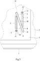
Fig. 5 illustrates an example of the operation of assembling the boards of the robot controller ofFig. 1 . -
Fig. 6 is a perspective view showing an exemplary configuration of a robot controller according to another embodiment of the present invention. - Hereinafter, embodiments of the present invention will be described with reference to the drawings. The present invention is not limited by the described embodiments. In the following description, the same or equivalent elements are denoted by the same reference signs throughout the drawings and will not be repeatedly described.
-
Fig. 1 is an exploded perspective view showing an exemplary configuration of arobot controller 100 according to an embodiment of the present invention. - The
robot controller 100 is an electronic device that controls the operation of an unillustrated robot. - As shown in
Fig. 1 , therobot controller 100 includes afirst board 1, asecond board 2, athird board 8, a board-to-board connector 3, agrip member 4, a pair ofspacers 5, a pair ofmale screws 6, and ahousing 7. - The
first board 1 is a printed circuit board having an electronic circuit component mounted thereon. Thefirst board 1 receives current command values, based on which thefirst board 1 controls currents to be supplied to servomotors provided at joints of the robot. The pattern of thefirst board 1 is designed to carry relatively high-current, high-voltage electricity to be supplied to the servomotors provided at the joints of the robot. Thefirst board 1 is disposed on and parallel to a later-describedbottom plate 72 of thehousing 7. However, this configuration is not limiting. For example, thefirst board 1 may be disposed on and perpendicular to the later-describedbottom plate 72 of the housing 7 (i.e., thefirst board 1 may be placed upright on the bottom plate 72). - The
second board 2 is a printed circuit board having an electronic circuit component mounted thereon. Thesecond board 2 is a board provided separately from thefirst board 1. When theboards second board 2 is stacked to thefirst board 1 and located outward of (above) afront side 11 of thefirst board 1. In the present embodiment, thesecond board 2 is stacked above thefirst board 1 disposed parallel to thebottom plate 72. However, this configuration is not limiting. In the case where thefirst board 1 is placed upright on thebottom plate 72, thesecond board 2 may be stacked lateral to thefirst board 1. The circuit of thesecond board 2 generates current command values based on specified target positions of the joints. The pattern of thesecond board 2 is designed to carry lower-current, lower-voltage electricity than the pattern of thefirst board 1. Configuring thefirst board 1 and thesecond board 2 as separate boards therefore allows effective prevention of short-circuiting between the circuit of thefirst board 1 and the circuit of thesecond board 2. Additionally, since thefirst board 1 and thesecond board 2 are configured as separate boards, a safety approval by an approving authority for a device of thefirst board 1 and a safety approval by the approving authority for a device of thesecond board 2 can be separately obtained. Thus, when the specification of one of the devices is changed, the need for obtaining a safety approval for the other device again is eliminated. - The
second board 2 has a pair of throughholes 23 formed at locations where the tip ends (upper ends) of the pair ofspacers 5 descried later make contact with thesecond board 2. The pair of throughholes 23 have a diameter that allows insertion of themale screws 6 described later into the through holes 23. - The
third board 8 is a printed circuit board having an electronic circuit component mounted thereon. Thethird board 8 is a board provided separately from the first andsecond boards third board 8 is stacked to the first andsecond boards second board 2. Thethird board 8 generates the target positions of the joints based on an operation program. In the present embodiment, thethird board 8 is so configured that thethird board 8 having been fixed to thesecond board 2 via a plurality ofspacers 81 is joined to thefirst board 1. Specifically, each of thespacers 81 has a base end (lower end) screwed to thesecond board 2 and a tip end (upper end) screwed to thethird board 8. - As described above, the
robot controller 100 uses thethird board 8 to generate and output the target positions based on the operation program. The outputted target positions are inputted to thesecond board 2 via the unillustrated board-to-board connector 3. Subsequently, thesecond board 2 generates and outputs current command values for the joints based on the inputted target positions of the joints. The outputted current command values are inputted to thefirst board 1 via the board-to-board connector 3. Thefirst board 1 then supplies currents to the joints based on the inputted current command values for the joints. -
Fig. 2 is a perspective view showing exemplary configurations of thesecond board 2 andthird board 8. - As shown in
Figs. 1 and 2 , the board-to-board connector 3 electrically connects thefirst board 1 and thesecond board 2 and, for example, allows the current command values for the joints to be outputted from thesecond board 2 to thefirst board 1. In the present embodiment, a pair of board-to-board connectors 3 are provided. - Each board-to-
board connector 3 includes afirst terminal 31 provided on thefirst board 1 and asecond terminal 32 provided on thesecond board 2, thesecond terminal 32 being configured to be connected to thefirst terminal 31. Thefirst terminal 31 is provided, for example, on thefront side 11 of thefirst board 1, and thesecond terminal 32 is provided, for example, on a back side 22 of thesecond board 2. In the board-to-board connector 3, for example, thesecond terminal 32 is a male terminal having a plurality of pins (electrical contact portion) extending in the direction in which the first andsecond boards second board 2 toward the first board 1 (downward direction), while thefirst terminal 31 is a female terminal having a pin socket (electrical contact portion) configured to receive thesecond terminal 32 fitted therein and make contact with the plurality of pins of thesecond terminal 32. Thus, thesecond terminal 32 is inserted into and connected to thefirst terminal 31 by lowering thesecond board 2 in the direction in which the first andsecond boards second terminal 32 is withdrawn and disconnected from thefirst terminal 31 by lifting thesecond board 2 in the direction in which thefirst board 1 and thesecond board 2 are stacked. In the present embodiment, as described above, a pair of board-to-board connectors 3 are provided, and the pair of board-to-board connectors 3 include a pair offirst terminals 31 and a pair ofsecond terminals 32. The pair offirst terminals 31 are mounted parallel to each other on thefront side 11 of thefirst board 1, and accordingly the pair ofsecond terminals 32 are mounted parallel to each other on the back side 22 of thesecond board 2. -
Fig. 3 is an enlarged view showing key components in an exemplary configuration of therobot controller 100. - The
grip member 4 is, for example, a handle-like member provided on thesecond board 2 and is formed in a shape adapted for gripping by a hand of an operator performing the operation of assembling the boards or the operation of inspecting the interior of therobot controller 100. Thegrip member 4 is provided on afront side 21 of thesecond board 2 and located in the vicinity of thesecond terminals 32. Thegrip member 4 includes, for example, a pair ofconnection portions 41 disposed on and extending from thefront side 21 of thesecond board 2 and agrip portion 42 connecting the tip ends (upper ends) of the pair ofconnection portions 41 to each other. Thegrip portion 42 is a portion to be gripped by the operator performing the assembly operation. As shown inFig. 3 , thegrip portion 42 as viewed in the direction of the normal to thefirst board 1 extends through a region A in which the board-to-board connectors 3 are located. In the present embodiment, the region A encloses the pair of board-to-board connectors 3. That is, when thegrip portion 42 and the region A are projected onto a projection plane parallel to the first andsecond boards grip portion 42 extends through the region A in the projection plane. - Unillustrated female threads are formed at the base ends (lower ends) of the pair of
connection portions 41 of thegrip member 4. A pair of unillustrated through holes are formed at locations where the pair ofconnection portions 41 of thegrip member 4 and thefront side 21 of thesecond board 2 make contact. A pair ofmale screws 43 shown inFig. 2 are inserted in the through holes from the back side 22 of thesecond board 2 toward thefront side 21 of thesecond board 2 and are screwed into the female threads of the pair ofconnection portions 41 of thegrip member 4. In this manner, thegrip member 4 is attached to thesecond board 2. - As shown in
Fig. 1 , the pair ofspacers 5 are disposed on and extend from either thefront side 11 of thefirst board 1 or the back side 22 of thesecond board 2, and are located in the vicinity of the board-to-board connectors 3. In the present embodiment, the pair ofspacers 5 are disposed on and extend from thefirst board 1. For example, the base ends (lower ends) of the pair ofspacers 5 are screwed to thefirst board 1. - Each of the pair of
spacers 5 has a length such that when thefirst terminal 31 and thesecond terminal 32 are connected, the base end of thespacer 5 is in contact with thefront side 11 of thefirst board 1, and the tip end (upper end) of thespacer 5 is in contact with the back side 22 of thesecond board 2. - The pair of
spacers 5 havefemale threads 51 formed at their respective tip ends. The pair ofspacers 5 as viewed in the direction of the normal to thesecond board 2 are arranged coaxially with the pair of throughholes 23 of thesecond board 2. The pair offemale threads 51 are engaged with the pair ofmale screws 6 inserted into the pair of throughholes 23 from thefront side 21 of thesecond board 2 toward the back side 22 of thesecond board 2. Thus, thesecond board 2 can be fixed to thefirst board 1. - Additionally, a plurality of
spacers 82, which, for example, have the same shape as thespacers 5, are disposed on and extend from thefirst board 1. Thesespacers 82 have base ends (lower ends) screwed to thefirst board 1 and tip ends (upper ends) screwed to thesecond board 2. Thus, thefirst board 1, thesecond board 2, and thethird board 8 are spaced apart in the stacking direction, so that, for example, the influence of noise among the boards is reduced. - The
housing 7 is box-shaped, and includes anopening 71 formed in the top surface thereof, abottom plate 72, aside wall 73, and an unillustrated lid closing theopening 71. Theopening 71 has a size that allows placement of the first andsecond boards housing 7 through theopening 71, and theopening 71 is located outward of (above) thefront side 21 of thesecond board 2. The first andsecond boards bottom plate 72. Thefirst board 1 is disposed above and fixed to thebottom plate 72 via unillustrated spacers. Thehousing 7 of therobot controller 100 is so configured that thehousing 7 may be vertically placed instead of being horizontally placed as shown inFig. 1 . That is, thehousing 7 of therobot controller 100 is so configured that thehousing 7 may be placed in a position where any one of the four surfaces constituting theside wall 73 faces downward with thebottom plate 72 vertically extending. - As described above, the first and
second boards bottom plate 72. Thus, the boards can be joined to thehousing 7 by stacking the boards in the operation of assembling the boards. This facilitates the operation of assembling the boards and offers an advantage, for example, in automating the assembly operation by means of a robot. - Next, an example of the operation of assembling the boards of the
robot controller 100 will be described. -
Figs. 4 and 5 illustrate an example of the operation of assembling the boards of therobot controller 100. - When mounting the second and
third boards robot controller 100, the operator performing the assembly operation holds thegrip portion 42 of thegrip member 4 and places the second andthird boards housing 7 through theopening 71 of thehousing 7. The operator roughly estimates the location where the second andthird boards third boards - Subsequently, the operator manipulates the
grip member 4 while looking through the pair of throughholes 23 at regions below the through holes 23 (in the direction from thesecond board 2 toward the first board 1) and places the second andthird boards holes 23 and the pair offemale threads 51 are coaxially arranged as shown inFig. 3 . - Subsequently, the operator manipulates the
grip member 4 to lower the second andthird boards 2 and 8 (bring the second andthird boards Fig. 4 while maintaining the coaxiality of the pair of throughholes 23 and the pair offemale threads 51. Thus, the pair ofsecond terminals 32 are inserted into the pair offirst terminals 31, and thefirst board 1 and thesecond board 2 are connected by the board-to-board connectors 3. Finally, themale screws 6 are screwed into thefemale threads 51 of thespacers 5 to fix the second andthird boards first board 1. In this manner, the second andthird boards first board 1. - When removing the second and
third boards first board 1, the operator removes the pair ofmale screws 6, holds thegrip member 4 and lifts the second andthird boards second terminals 32 are withdrawn from thefirst terminals 31, and the connection via the board-to-board connectors 3 is broken. - In the
robot controller 100 of the present embodiment, as described above, thesecond board 2 can be connected to thefirst board 1 via the board-to-board connectors 3 by lowering the second andthird boards - Additionally, since the operation of making a connection via the board-to-
board connectors 3 and the operation of breaking the connection can be performed while gripping thegrip member 4, thesecond board 2 can be prevented from being bent and damaged when thesecond board 2 is pushed downward to insert thesecond terminals 32 into thefirst terminals 31 or thesecond board 2 is lifted upward to withdraw thesecond terminals 32 from thefirst terminals 31. Further, the operator performing the operations can be prevented from directly touching the boards and thereby causing electrostatic breakdown of the electronic circuit components. - Additionally, since the
grip portion 42 of thegrip member 4, as viewed in the direction of the normal to thefirst board 1, extends through the region A in which the board-to-board connectors 3 are located, the force applied by pushing thegrip member 4 downward can be efficiently transmitted as a force acting to insert thesecond terminals 32 into thefirst terminals 31 when the connection via the board-to-board connectors 3 is made. Further, when the connection via the board-to-board connector 3 is broken, the force applied by pulling thegrip member 4 upward can be efficiently transmitted as a force acting to withdraw thesecond terminals 32 from thefirst terminals 31. - When the
first terminals 31 and thesecond terminals 32 of the board-to-board connectors 3 are connected, thesecond board 2 can be accurately and easily positioned relative to thefirst board 1 by making an adjustment such that the pair of throughholes 23 and the pair offemale threads 51 are coaxially arranged. Thus, even in the case where thefirst terminals 31 and thesecond terminals 32 are difficult to look at from a lateral side of a space between thefirst board 1 and thesecond board 2, thefirst terminals 31 and thesecond terminals 32 can be easily and reliably connected. - Once the upper end of the
spacer 5 and the back side 22 of thesecond board 2 come into contact as shown inFig. 5 , the movement of the second andthird boards second board 2 toward the first board 1) is restricted. Thus, the depth of insertion of thesecond terminal 32 into thefirst terminal 31 can be appropriately defined by thespacer 5. This can prevent the second terminal 32 from being inserted so deep into thefirst terminal 31 that an unnecessarily large force is applied to the first andsecond terminals second terminals spacers 5, the depth of insertion of thesecond terminals 32 into thefirst terminals 31 can be more appropriately defined by the pair ofspacers 5. -
Fig. 6 is a perspective view showing an exemplary configuration of arobot controller 200 according to another embodiment of the present invention. - In the present embodiment, as shown in
Fig. 6 , asecond board 202 is located above thefirst board 1 and placed in such a position as to intersect (in particular, perpendicularly intersect) thefirst board 1. The other features of thesecond board 202 are the same as those of thesecond board 2 and will therefore not be described in detail. - A board-to-
board connector 203 has asecond terminal 232 extending in a direction toward thefirst board 1 from a portion of the periphery of either a front side 221 or a back side 222 of thesecond board 202, the portion facing thefirst board 1. The other features of the board-to-board connector 203 are the same as those of the board-to-board connector 3 and will therefore not be described in detail. - A
grip member 204 includes aconnection portion 241 disposed on and extending from thefront side 21 of thesecond board 2 and agrip portion 242 extending from the tip end of theconnection portion 241. Theconnection portion 241 is curved at its central portion to have an L-shape. The part of theconnection portion 241 that is closer to the base end than is the curved portion extends in a direction orthogonal to thesecond board 2, while the part that is closer to the tip end than is the curved portion extends in a direction orthogonal to thefirst board 1. Thegrip portion 242 extends parallel to thefirst board 1 and thesecond board 2. The other features of thegrip member 204 are the same as those of thegrip member 4 and will therefore not be described in detail. - Many modifications and other embodiments of the present invention will be apparent to those skilled in the art from the foregoing description. Accordingly, the foregoing description is to be construed as illustrative only, and is provided for the purpose of teaching those skilled in the art the best mode for carrying out the invention. The details of the structure and/or function may be varied substantially without departing from the scope of the invention.
-
- 1 First board
- 2 Second board
- 3 Board-to-board connector
- 4 Grip member
- 31 First terminal (of board-to-board connector)
- 32 Second terminal (of board-to-board connector)
- 100 Robot controller
Claims (10)
- An electronic device comprising:a first board configured as a printed circuit board having an electronic circuit component mounted thereon;a second board configured as a printed circuit board having an electronic circuit component mounted thereon;a board-to-board connector configured to electrically connect the first board and the second board, the board-to-board connector comprising a first terminal provided on the first board and a second terminal provided on the second board, the second terminal being configured to be connected to the first terminal; anda grip member provided on the second board.
- The electronic device according to claim 1, wherein
the second board is stacked to the first board,
the first terminal is provided on a front side of the first board,
the second terminal is provided on a back side of the second board, and
the grip member is provided on a front side of the second board. - The electronic device according to claim 2, wherein
one of the first and second terminals of the board-to-board connector is a male terminal having an electrical contact portion extending in a direction in which the first and second boards are stacked, and
the other of the first and second terminals is a female terminal having an electrical contact portion configured to receive the male terminal fitted therein and make contact with the electrical contact portion of the male terminal. - The electronic device according to claim 2 or 3, wherein the grip member, as viewed in a direction of a normal to the first board, extends through a region in which the board-to-board connector is located.
- The electronic device according to any one of claims 2 to 4, further comprising a spacer disposed on and extending from either the front side of the first board or the back side of the second board, the spacer having a length such that when the first terminal and the second terminal are connected, one end of the spacer is in contact with the front side of the first board and the other end of the spacer is in contact with the back side of the second board.
- The electronic device according to claim 5, comprising a pair of the spacers.
- The electronic device according to claim 6, wherein
the pair of spacers are provided on the first board, and
the second board has a pair of through holes at locations where the other ends of the pair of spacers make contact with the second board. - The electronic device according to claim 7, wherein
a female thread is formed in the other end of each of the spacers, and
the electronic device further comprises a pair of male screws inserted through the pair of through holes and screwed into the female threads of the pair of spacers. - The electronic device according to any one of claims 1 to 8, further comprising a housing having an opening, wherein
the opening has a size that allows placement of the first and second boards into the housing through the opening, and
the opening is located outward of a front side of the second board. - A robot controller comprising:a first board configured as a printed circuit board having an electronic circuit component mounted thereon;a second board configured as a printed circuit board having an electronic circuit component mounted thereon;a board-to-board connector configured to electrically connect the first board and the second board, the board-to-board connector comprising a first terminal provided on the first board and a second terminal provided on the second board, the second terminal being configured to be connected to the first terminal; anda grip member provided on the second board.
Applications Claiming Priority (2)
| Application Number | Priority Date | Filing Date | Title |
|---|---|---|---|
| JP2017035060A JP7051297B2 (en) | 2017-02-27 | 2017-02-27 | Electronic devices and robot controllers |
| PCT/JP2018/007140 WO2018155702A1 (en) | 2017-02-27 | 2018-02-27 | Electronic device and robot controller |
Publications (3)
| Publication Number | Publication Date |
|---|---|
| EP3589088A1 true EP3589088A1 (en) | 2020-01-01 |
| EP3589088A4 EP3589088A4 (en) | 2020-12-30 |
| EP3589088B1 EP3589088B1 (en) | 2023-04-12 |
Family
ID=63252699
Family Applications (1)
| Application Number | Title | Priority Date | Filing Date |
|---|---|---|---|
| EP18758470.1A Active EP3589088B1 (en) | 2017-02-27 | 2018-02-27 | Electronic device and robot controller |
Country Status (6)
| Country | Link |
|---|---|
| US (1) | US10965059B2 (en) |
| EP (1) | EP3589088B1 (en) |
| JP (1) | JP7051297B2 (en) |
| KR (1) | KR20190112107A (en) |
| CN (1) | CN110326372B (en) |
| WO (1) | WO2018155702A1 (en) |
Cited By (1)
| Publication number | Priority date | Publication date | Assignee | Title |
|---|---|---|---|---|
| WO2022008210A1 (en) * | 2020-07-09 | 2022-01-13 | Robert Bosch Gmbh | Electronics unit for an electrical device |
Families Citing this family (11)
| Publication number | Priority date | Publication date | Assignee | Title |
|---|---|---|---|---|
| DE202018104586U1 (en) * | 2018-08-09 | 2019-11-19 | Sma Solar Technology Ag | DC link arrangement and inverter |
| JP7384618B2 (en) * | 2019-10-23 | 2023-11-21 | ファナック株式会社 | Connection structure and assembly |
| US11357103B1 (en) * | 2020-01-21 | 2022-06-07 | Signetik, LLC | System-in-package cellular assembly |
| CN111682331A (en) * | 2020-08-17 | 2020-09-18 | 深圳微步信息股份有限公司 | Multifunctional extended circuit board module and mobile terminal |
| US12095189B2 (en) * | 2020-12-24 | 2024-09-17 | Intel Corporation | Ultra slim module form factor and connector architecture for top mount connection |
| CN113286447B (en) * | 2021-05-06 | 2022-09-02 | 成都哈工驱动科技有限公司 | Processing technology of servo driver with copper eyelet structure |
| JP7758522B2 (en) * | 2021-09-28 | 2025-10-22 | TE Connectivity Japan合同会社 | socket |
| JP7859032B2 (en) * | 2021-10-13 | 2026-05-15 | 株式会社Jvcケンウッド | Enclosure structure |
| CN114221160A (en) * | 2021-11-10 | 2022-03-22 | 北京无线电测量研究所 | Test tool and manufacturing method thereof |
| JP7816049B2 (en) * | 2022-09-08 | 2026-02-18 | サクサ株式会社 | Substrate attachment/detachment member and substrate attachment/detachment structure |
| US12432855B2 (en) * | 2023-03-07 | 2025-09-30 | SanDisk Technologies, Inc. | Multiple circuit board assembly including a support element and method of manufacture thereof |
Family Cites Families (16)
| Publication number | Priority date | Publication date | Assignee | Title |
|---|---|---|---|---|
| JPS5996888U (en) * | 1982-12-20 | 1984-06-30 | 日本電気株式会社 | Electronic equipment housing equipment |
| US4546414A (en) * | 1983-04-12 | 1985-10-08 | Nordson Corporation | Plug-in circuit board connector and keying assembly |
| US4620362A (en) * | 1984-06-22 | 1986-11-04 | The Boeing Company | Changeable tooling system for robot end-effector |
| JPS62283696A (en) * | 1986-06-02 | 1987-12-09 | キヤノン株式会社 | Printed board |
| JPH0716304Y2 (en) * | 1990-01-19 | 1995-04-12 | 富士通株式会社 | Memory circuit protection structure |
| US5425133A (en) * | 1990-01-24 | 1995-06-13 | Canon Kabushiki Kaisha | Robot apparatus with an electrical driver for controlling a detachable rotor hand |
| JPH0432292A (en) * | 1990-05-29 | 1992-02-04 | Mitsubishi Electric Corp | Connection structure of printed wiring board |
| US5205701A (en) * | 1990-06-04 | 1993-04-27 | Canon Kabushiki Kaisha | Industrial robot |
| JPH04102594U (en) * | 1991-02-01 | 1992-09-03 | 富士通テン株式会社 | Multilayer board attachment/detachment mechanism |
| JPH08330699A (en) * | 1995-05-30 | 1996-12-13 | Nec Corp | Printed wiring board and mounting method between them |
| JPH11135910A (en) * | 1997-10-31 | 1999-05-21 | Fujitsu Ltd | Shelf mounting structure of printed circuit board |
| JP2003188489A (en) * | 2001-12-14 | 2003-07-04 | Pentax Corp | Electronic scope board structure |
| JP2005150161A (en) | 2003-11-11 | 2005-06-09 | Canon Inc | Printed wiring board connection structure |
| JP2011134868A (en) * | 2009-12-24 | 2011-07-07 | Yamaha Corp | Printed circuit board mounting structure |
| WO2015116094A1 (en) * | 2014-01-30 | 2015-08-06 | Hewlett-Packard Development Company, L.P. | Mounting device |
| JP2015157154A (en) | 2015-06-08 | 2015-09-03 | 株式会社大都技研 | game machine |
-
2017
- 2017-02-27 JP JP2017035060A patent/JP7051297B2/en active Active
-
2018
- 2018-02-27 KR KR1020197025704A patent/KR20190112107A/en not_active Ceased
- 2018-02-27 WO PCT/JP2018/007140 patent/WO2018155702A1/en not_active Ceased
- 2018-02-27 US US16/489,094 patent/US10965059B2/en active Active
- 2018-02-27 CN CN201880014093.XA patent/CN110326372B/en active Active
- 2018-02-27 EP EP18758470.1A patent/EP3589088B1/en active Active
Cited By (1)
| Publication number | Priority date | Publication date | Assignee | Title |
|---|---|---|---|---|
| WO2022008210A1 (en) * | 2020-07-09 | 2022-01-13 | Robert Bosch Gmbh | Electronics unit for an electrical device |
Also Published As
| Publication number | Publication date |
|---|---|
| JP7051297B2 (en) | 2022-04-11 |
| WO2018155702A1 (en) | 2018-08-30 |
| US10965059B2 (en) | 2021-03-30 |
| US20200076124A1 (en) | 2020-03-05 |
| CN110326372B (en) | 2022-12-30 |
| CN110326372A (en) | 2019-10-11 |
| EP3589088B1 (en) | 2023-04-12 |
| EP3589088A4 (en) | 2020-12-30 |
| JP2018142587A (en) | 2018-09-13 |
| KR20190112107A (en) | 2019-10-02 |
Similar Documents
| Publication | Publication Date | Title |
|---|---|---|
| US10965059B2 (en) | Electronic device and robot controller | |
| US9812801B2 (en) | Cable holding member, plug connector, connector device, flat cable, and method for assembling plug connector | |
| CN105103377B (en) | Plug-in device | |
| US20110256740A1 (en) | Connector that enables connection between circuit boards with excellent space efficiency | |
| EP3136512B1 (en) | Connector | |
| TWI919462B (en) | High density electrical connectors and terminal thereof | |
| US20110216512A1 (en) | Low Cost PCB Carrier and Connectivity System For Enclosed Electronics | |
| US20220285868A1 (en) | Plug connector and connector set having same, and method for removing connector set | |
| CN109586121B (en) | Plug device and power distribution system | |
| EP3319177B1 (en) | Modularized structure of switch wire connection device | |
| EP3876353B1 (en) | Terminal block and terminal block set | |
| US20190387625A1 (en) | Electric product | |
| CN107006118B (en) | Electrical device | |
| JP2015049954A (en) | Pin header | |
| CN113196577A (en) | Multi-piece printed circuit board adapter plug | |
| CN106104932A (en) | Circuit board break-through connects terminal | |
| JP2013030291A (en) | Connector holding structure, electronic apparatus, and motor controller | |
| CN105849978A (en) | Test cables and socket adapters for test cables | |
| CN106025694B (en) | Electric connector system with laterally projecting release arm | |
| US20120309223A1 (en) | Guide element for a connector device | |
| US20200203863A1 (en) | Circuit board assembly | |
| JP2011228297A (en) | Usb plug socket | |
| JP2021019132A (en) | Method of removing circuit board | |
| JP6052084B2 (en) | Electrical junction box | |
| CN103762454B (en) | Connector error-proof structure |
Legal Events
| Date | Code | Title | Description |
|---|---|---|---|
| STAA | Information on the status of an ep patent application or granted ep patent |
Free format text: STATUS: THE INTERNATIONAL PUBLICATION HAS BEEN MADE |
|
| PUAI | Public reference made under article 153(3) epc to a published international application that has entered the european phase |
Free format text: ORIGINAL CODE: 0009012 |
|
| STAA | Information on the status of an ep patent application or granted ep patent |
Free format text: STATUS: REQUEST FOR EXAMINATION WAS MADE |
|
| 17P | Request for examination filed |
Effective date: 20190827 |
|
| AK | Designated contracting states |
Kind code of ref document: A1 Designated state(s): AL AT BE BG CH CY CZ DE DK EE ES FI FR GB GR HR HU IE IS IT LI LT LU LV MC MK MT NL NO PL PT RO RS SE SI SK SM TR |
|
| AX | Request for extension of the european patent |
Extension state: BA ME |
|
| DAV | Request for validation of the european patent (deleted) | ||
| DAX | Request for extension of the european patent (deleted) | ||
| A4 | Supplementary search report drawn up and despatched |
Effective date: 20201130 |
|
| RIC1 | Information provided on ipc code assigned before grant |
Ipc: H05K 1/14 20060101AFI20201124BHEP Ipc: H05K 7/14 20060101ALI20201124BHEP Ipc: B25J 19/00 20060101ALI20201124BHEP Ipc: B25J 13/06 20060101ALI20201124BHEP |
|
| REG | Reference to a national code |
Ref country code: DE Ref legal event code: R079 Ref document number: 602018048334 Country of ref document: DE Free format text: PREVIOUS MAIN CLASS: H05K0001140000 Ipc: H01R0012730000 |
|
| GRAP | Despatch of communication of intention to grant a patent |
Free format text: ORIGINAL CODE: EPIDOSNIGR1 |
|
| STAA | Information on the status of an ep patent application or granted ep patent |
Free format text: STATUS: GRANT OF PATENT IS INTENDED |
|
| RIC1 | Information provided on ipc code assigned before grant |
Ipc: H05K 1/14 20060101ALI20221010BHEP Ipc: B25J 19/00 20060101ALI20221010BHEP Ipc: H05K 7/14 20060101ALI20221010BHEP Ipc: H05K 3/36 20060101ALI20221010BHEP Ipc: H02K 11/30 20160101ALI20221010BHEP Ipc: H01R 12/73 20110101AFI20221010BHEP |
|
| INTG | Intention to grant announced |
Effective date: 20221027 |
|
| GRAS | Grant fee paid |
Free format text: ORIGINAL CODE: EPIDOSNIGR3 |
|
| GRAA | (expected) grant |
Free format text: ORIGINAL CODE: 0009210 |
|
| STAA | Information on the status of an ep patent application or granted ep patent |
Free format text: STATUS: THE PATENT HAS BEEN GRANTED |
|
| AK | Designated contracting states |
Kind code of ref document: B1 Designated state(s): AL AT BE BG CH CY CZ DE DK EE ES FI FR GB GR HR HU IE IS IT LI LT LU LV MC MK MT NL NO PL PT RO RS SE SI SK SM TR |
|
| REG | Reference to a national code |
Ref country code: GB Ref legal event code: FG4D |
|
| REG | Reference to a national code |
Ref country code: CH Ref legal event code: EP |
|
| REG | Reference to a national code |
Ref country code: DE Ref legal event code: R096 Ref document number: 602018048334 Country of ref document: DE |
|
| REG | Reference to a national code |
Ref country code: IE Ref legal event code: FG4D |
|
| REG | Reference to a national code |
Ref country code: AT Ref legal event code: REF Ref document number: 1560314 Country of ref document: AT Kind code of ref document: T Effective date: 20230515 |
|
| REG | Reference to a national code |
Ref country code: LT Ref legal event code: MG9D |
|
| REG | Reference to a national code |
Ref country code: NL Ref legal event code: MP Effective date: 20230412 |
|
| REG | Reference to a national code |
Ref country code: AT Ref legal event code: MK05 Ref document number: 1560314 Country of ref document: AT Kind code of ref document: T Effective date: 20230412 |
|
| PG25 | Lapsed in a contracting state [announced via postgrant information from national office to epo] |
Ref country code: NL Free format text: LAPSE BECAUSE OF FAILURE TO SUBMIT A TRANSLATION OF THE DESCRIPTION OR TO PAY THE FEE WITHIN THE PRESCRIBED TIME-LIMIT Effective date: 20230412 |
|
| PG25 | Lapsed in a contracting state [announced via postgrant information from national office to epo] |
Ref country code: SE Free format text: LAPSE BECAUSE OF FAILURE TO SUBMIT A TRANSLATION OF THE DESCRIPTION OR TO PAY THE FEE WITHIN THE PRESCRIBED TIME-LIMIT Effective date: 20230412 Ref country code: PT Free format text: LAPSE BECAUSE OF FAILURE TO SUBMIT A TRANSLATION OF THE DESCRIPTION OR TO PAY THE FEE WITHIN THE PRESCRIBED TIME-LIMIT Effective date: 20230814 Ref country code: NO Free format text: LAPSE BECAUSE OF FAILURE TO SUBMIT A TRANSLATION OF THE DESCRIPTION OR TO PAY THE FEE WITHIN THE PRESCRIBED TIME-LIMIT Effective date: 20230712 Ref country code: ES Free format text: LAPSE BECAUSE OF FAILURE TO SUBMIT A TRANSLATION OF THE DESCRIPTION OR TO PAY THE FEE WITHIN THE PRESCRIBED TIME-LIMIT Effective date: 20230412 Ref country code: AT Free format text: LAPSE BECAUSE OF FAILURE TO SUBMIT A TRANSLATION OF THE DESCRIPTION OR TO PAY THE FEE WITHIN THE PRESCRIBED TIME-LIMIT Effective date: 20230412 |
|
| PG25 | Lapsed in a contracting state [announced via postgrant information from national office to epo] |
Ref country code: RS Free format text: LAPSE BECAUSE OF FAILURE TO SUBMIT A TRANSLATION OF THE DESCRIPTION OR TO PAY THE FEE WITHIN THE PRESCRIBED TIME-LIMIT Effective date: 20230412 Ref country code: PL Free format text: LAPSE BECAUSE OF FAILURE TO SUBMIT A TRANSLATION OF THE DESCRIPTION OR TO PAY THE FEE WITHIN THE PRESCRIBED TIME-LIMIT Effective date: 20230412 Ref country code: LV Free format text: LAPSE BECAUSE OF FAILURE TO SUBMIT A TRANSLATION OF THE DESCRIPTION OR TO PAY THE FEE WITHIN THE PRESCRIBED TIME-LIMIT Effective date: 20230412 Ref country code: LT Free format text: LAPSE BECAUSE OF FAILURE TO SUBMIT A TRANSLATION OF THE DESCRIPTION OR TO PAY THE FEE WITHIN THE PRESCRIBED TIME-LIMIT Effective date: 20230412 Ref country code: IS Free format text: LAPSE BECAUSE OF FAILURE TO SUBMIT A TRANSLATION OF THE DESCRIPTION OR TO PAY THE FEE WITHIN THE PRESCRIBED TIME-LIMIT Effective date: 20230812 Ref country code: HR Free format text: LAPSE BECAUSE OF FAILURE TO SUBMIT A TRANSLATION OF THE DESCRIPTION OR TO PAY THE FEE WITHIN THE PRESCRIBED TIME-LIMIT Effective date: 20230412 Ref country code: GR Free format text: LAPSE BECAUSE OF FAILURE TO SUBMIT A TRANSLATION OF THE DESCRIPTION OR TO PAY THE FEE WITHIN THE PRESCRIBED TIME-LIMIT Effective date: 20230713 Ref country code: AL Free format text: LAPSE BECAUSE OF FAILURE TO SUBMIT A TRANSLATION OF THE DESCRIPTION OR TO PAY THE FEE WITHIN THE PRESCRIBED TIME-LIMIT Effective date: 20230412 |
|
| PG25 | Lapsed in a contracting state [announced via postgrant information from national office to epo] |
Ref country code: FI Free format text: LAPSE BECAUSE OF FAILURE TO SUBMIT A TRANSLATION OF THE DESCRIPTION OR TO PAY THE FEE WITHIN THE PRESCRIBED TIME-LIMIT Effective date: 20230412 |
|
| REG | Reference to a national code |
Ref country code: DE Ref legal event code: R097 Ref document number: 602018048334 Country of ref document: DE |
|
| PG25 | Lapsed in a contracting state [announced via postgrant information from national office to epo] |
Ref country code: SK Free format text: LAPSE BECAUSE OF FAILURE TO SUBMIT A TRANSLATION OF THE DESCRIPTION OR TO PAY THE FEE WITHIN THE PRESCRIBED TIME-LIMIT Effective date: 20230412 |
|
| PG25 | Lapsed in a contracting state [announced via postgrant information from national office to epo] |
Ref country code: SM Free format text: LAPSE BECAUSE OF FAILURE TO SUBMIT A TRANSLATION OF THE DESCRIPTION OR TO PAY THE FEE WITHIN THE PRESCRIBED TIME-LIMIT Effective date: 20230412 Ref country code: SK Free format text: LAPSE BECAUSE OF FAILURE TO SUBMIT A TRANSLATION OF THE DESCRIPTION OR TO PAY THE FEE WITHIN THE PRESCRIBED TIME-LIMIT Effective date: 20230412 Ref country code: RO Free format text: LAPSE BECAUSE OF FAILURE TO SUBMIT A TRANSLATION OF THE DESCRIPTION OR TO PAY THE FEE WITHIN THE PRESCRIBED TIME-LIMIT Effective date: 20230412 Ref country code: EE Free format text: LAPSE BECAUSE OF FAILURE TO SUBMIT A TRANSLATION OF THE DESCRIPTION OR TO PAY THE FEE WITHIN THE PRESCRIBED TIME-LIMIT Effective date: 20230412 Ref country code: DK Free format text: LAPSE BECAUSE OF FAILURE TO SUBMIT A TRANSLATION OF THE DESCRIPTION OR TO PAY THE FEE WITHIN THE PRESCRIBED TIME-LIMIT Effective date: 20230412 Ref country code: CZ Free format text: LAPSE BECAUSE OF FAILURE TO SUBMIT A TRANSLATION OF THE DESCRIPTION OR TO PAY THE FEE WITHIN THE PRESCRIBED TIME-LIMIT Effective date: 20230412 |
|
| PLBE | No opposition filed within time limit |
Free format text: ORIGINAL CODE: 0009261 |
|
| STAA | Information on the status of an ep patent application or granted ep patent |
Free format text: STATUS: NO OPPOSITION FILED WITHIN TIME LIMIT |
|
| 26N | No opposition filed |
Effective date: 20240115 |
|
| PG25 | Lapsed in a contracting state [announced via postgrant information from national office to epo] |
Ref country code: SI Free format text: LAPSE BECAUSE OF FAILURE TO SUBMIT A TRANSLATION OF THE DESCRIPTION OR TO PAY THE FEE WITHIN THE PRESCRIBED TIME-LIMIT Effective date: 20230412 |
|
| PG25 | Lapsed in a contracting state [announced via postgrant information from national office to epo] |
Ref country code: SI Free format text: LAPSE BECAUSE OF FAILURE TO SUBMIT A TRANSLATION OF THE DESCRIPTION OR TO PAY THE FEE WITHIN THE PRESCRIBED TIME-LIMIT Effective date: 20230412 Ref country code: IT Free format text: LAPSE BECAUSE OF FAILURE TO SUBMIT A TRANSLATION OF THE DESCRIPTION OR TO PAY THE FEE WITHIN THE PRESCRIBED TIME-LIMIT Effective date: 20230412 |
|
| PG25 | Lapsed in a contracting state [announced via postgrant information from national office to epo] |
Ref country code: MC Free format text: LAPSE BECAUSE OF FAILURE TO SUBMIT A TRANSLATION OF THE DESCRIPTION OR TO PAY THE FEE WITHIN THE PRESCRIBED TIME-LIMIT Effective date: 20230412 |
|
| REG | Reference to a national code |
Ref country code: CH Ref legal event code: PL |
|
| PG25 | Lapsed in a contracting state [announced via postgrant information from national office to epo] |
Ref country code: LU Free format text: LAPSE BECAUSE OF NON-PAYMENT OF DUE FEES Effective date: 20240227 |
|
| PG25 | Lapsed in a contracting state [announced via postgrant information from national office to epo] |
Ref country code: CH Free format text: LAPSE BECAUSE OF NON-PAYMENT OF DUE FEES Effective date: 20240229 |
|
| PG25 | Lapsed in a contracting state [announced via postgrant information from national office to epo] |
Ref country code: LU Free format text: LAPSE BECAUSE OF NON-PAYMENT OF DUE FEES Effective date: 20240227 Ref country code: CH Free format text: LAPSE BECAUSE OF NON-PAYMENT OF DUE FEES Effective date: 20240229 |
|
| PG25 | Lapsed in a contracting state [announced via postgrant information from national office to epo] |
Ref country code: BG Free format text: LAPSE BECAUSE OF FAILURE TO SUBMIT A TRANSLATION OF THE DESCRIPTION OR TO PAY THE FEE WITHIN THE PRESCRIBED TIME-LIMIT Effective date: 20230412 |
|
| PG25 | Lapsed in a contracting state [announced via postgrant information from national office to epo] |
Ref country code: BG Free format text: LAPSE BECAUSE OF FAILURE TO SUBMIT A TRANSLATION OF THE DESCRIPTION OR TO PAY THE FEE WITHIN THE PRESCRIBED TIME-LIMIT Effective date: 20230412 |
|
| REG | Reference to a national code |
Ref country code: BE Ref legal event code: MM Effective date: 20240229 |
|
| PG25 | Lapsed in a contracting state [announced via postgrant information from national office to epo] |
Ref country code: BE Free format text: LAPSE BECAUSE OF NON-PAYMENT OF DUE FEES Effective date: 20240229 |
|
| PG25 | Lapsed in a contracting state [announced via postgrant information from national office to epo] |
Ref country code: IE Free format text: LAPSE BECAUSE OF NON-PAYMENT OF DUE FEES Effective date: 20240227 |
|
| PG25 | Lapsed in a contracting state [announced via postgrant information from national office to epo] |
Ref country code: IE Free format text: LAPSE BECAUSE OF NON-PAYMENT OF DUE FEES Effective date: 20240227 Ref country code: BE Free format text: LAPSE BECAUSE OF NON-PAYMENT OF DUE FEES Effective date: 20240229 |
|
| PG25 | Lapsed in a contracting state [announced via postgrant information from national office to epo] |
Ref country code: CY Free format text: LAPSE BECAUSE OF FAILURE TO SUBMIT A TRANSLATION OF THE DESCRIPTION OR TO PAY THE FEE WITHIN THE PRESCRIBED TIME-LIMIT; INVALID AB INITIO Effective date: 20180227 |
|
| PG25 | Lapsed in a contracting state [announced via postgrant information from national office to epo] |
Ref country code: HU Free format text: LAPSE BECAUSE OF FAILURE TO SUBMIT A TRANSLATION OF THE DESCRIPTION OR TO PAY THE FEE WITHIN THE PRESCRIBED TIME-LIMIT; INVALID AB INITIO Effective date: 20180227 |
|
| PG25 | Lapsed in a contracting state [announced via postgrant information from national office to epo] |
Ref country code: TR Free format text: LAPSE BECAUSE OF FAILURE TO SUBMIT A TRANSLATION OF THE DESCRIPTION OR TO PAY THE FEE WITHIN THE PRESCRIBED TIME-LIMIT Effective date: 20230412 |
|
| PGFP | Annual fee paid to national office [announced via postgrant information from national office to epo] |
Ref country code: FR Payment date: 20251231 Year of fee payment: 9 |
|
| PGFP | Annual fee paid to national office [announced via postgrant information from national office to epo] |
Ref country code: GB Payment date: 20260106 Year of fee payment: 9 |
|
| PGFP | Annual fee paid to national office [announced via postgrant information from national office to epo] |
Ref country code: DE Payment date: 20260102 Year of fee payment: 9 |