EP3589052B1 - Procédé d'indication de ressources, dispositif terminal et dispositif de réseau - Google Patents
Procédé d'indication de ressources, dispositif terminal et dispositif de réseau Download PDFInfo
- Publication number
- EP3589052B1 EP3589052B1 EP18899971.8A EP18899971A EP3589052B1 EP 3589052 B1 EP3589052 B1 EP 3589052B1 EP 18899971 A EP18899971 A EP 18899971A EP 3589052 B1 EP3589052 B1 EP 3589052B1
- Authority
- EP
- European Patent Office
- Prior art keywords
- dmrs
- resource unit
- shared channel
- occupied
- physical shared
- Prior art date
- Legal status (The legal status is an assumption and is not a legal conclusion. Google has not performed a legal analysis and makes no representation as to the accuracy of the status listed.)
- Active
Links
- 238000000034 method Methods 0.000 title claims description 114
- 238000013507 mapping Methods 0.000 claims description 300
- 238000004590 computer program Methods 0.000 claims description 13
- 238000012545 processing Methods 0.000 claims description 13
- 230000011664 signaling Effects 0.000 description 71
- 238000004891 communication Methods 0.000 description 33
- 230000005540 biological transmission Effects 0.000 description 28
- 238000010586 diagram Methods 0.000 description 26
- 230000006870 function Effects 0.000 description 13
- 230000008569 process Effects 0.000 description 13
- 238000005516 engineering process Methods 0.000 description 12
- 230000009471 action Effects 0.000 description 4
- 230000008878 coupling Effects 0.000 description 3
- 238000010168 coupling process Methods 0.000 description 3
- 238000005859 coupling reaction Methods 0.000 description 3
- 238000013461 design Methods 0.000 description 3
- VJYFKVYYMZPMAB-UHFFFAOYSA-N ethoprophos Chemical compound CCCSP(=O)(OCC)SCCC VJYFKVYYMZPMAB-UHFFFAOYSA-N 0.000 description 3
- 230000001413 cellular effect Effects 0.000 description 2
- 230000003247 decreasing effect Effects 0.000 description 2
- 230000000977 initiatory effect Effects 0.000 description 2
- 230000007774 longterm Effects 0.000 description 2
- 238000010295 mobile communication Methods 0.000 description 2
- 241000760358 Enodes Species 0.000 description 1
- 101000741965 Homo sapiens Inactive tyrosine-protein kinase PRAG1 Proteins 0.000 description 1
- 102100038659 Inactive tyrosine-protein kinase PRAG1 Human genes 0.000 description 1
- 101150069124 RAN1 gene Proteins 0.000 description 1
- 101100355633 Salmo salar ran gene Proteins 0.000 description 1
- 230000008859 change Effects 0.000 description 1
- 238000011161 development Methods 0.000 description 1
- PCHJSUWPFVWCPO-UHFFFAOYSA-N gold Chemical group [Au] PCHJSUWPFVWCPO-UHFFFAOYSA-N 0.000 description 1
- 238000002955 isolation Methods 0.000 description 1
- 239000000203 mixture Substances 0.000 description 1
- 238000012986 modification Methods 0.000 description 1
- 230000004048 modification Effects 0.000 description 1
- 230000003287 optical effect Effects 0.000 description 1
- 238000013468 resource allocation Methods 0.000 description 1
- 238000012772 sequence design Methods 0.000 description 1
- 230000003595 spectral effect Effects 0.000 description 1
- 238000001228 spectrum Methods 0.000 description 1
Images


Classifications
-
- H—ELECTRICITY
- H04—ELECTRIC COMMUNICATION TECHNIQUE
- H04W—WIRELESS COMMUNICATION NETWORKS
- H04W72/00—Local resource management
- H04W72/20—Control channels or signalling for resource management
- H04W72/23—Control channels or signalling for resource management in the downlink direction of a wireless link, i.e. towards a terminal
-
- H—ELECTRICITY
- H04—ELECTRIC COMMUNICATION TECHNIQUE
- H04L—TRANSMISSION OF DIGITAL INFORMATION, e.g. TELEGRAPHIC COMMUNICATION
- H04L5/00—Arrangements affording multiple use of the transmission path
- H04L5/003—Arrangements for allocating sub-channels of the transmission path
- H04L5/0048—Allocation of pilot signals, i.e. of signals known to the receiver
-
- H—ELECTRICITY
- H04—ELECTRIC COMMUNICATION TECHNIQUE
- H04L—TRANSMISSION OF DIGITAL INFORMATION, e.g. TELEGRAPHIC COMMUNICATION
- H04L5/00—Arrangements affording multiple use of the transmission path
- H04L5/0091—Signaling for the administration of the divided path
- H04L5/0094—Indication of how sub-channels of the path are allocated
-
- H—ELECTRICITY
- H04—ELECTRIC COMMUNICATION TECHNIQUE
- H04L—TRANSMISSION OF DIGITAL INFORMATION, e.g. TELEGRAPHIC COMMUNICATION
- H04L5/00—Arrangements affording multiple use of the transmission path
- H04L5/003—Arrangements for allocating sub-channels of the transmission path
- H04L5/0048—Allocation of pilot signals, i.e. of signals known to the receiver
- H04L5/0051—Allocation of pilot signals, i.e. of signals known to the receiver of dedicated pilots, i.e. pilots destined for a single user or terminal
-
- H—ELECTRICITY
- H04—ELECTRIC COMMUNICATION TECHNIQUE
- H04W—WIRELESS COMMUNICATION NETWORKS
- H04W72/00—Local resource management
- H04W72/04—Wireless resource allocation
-
- H—ELECTRICITY
- H04—ELECTRIC COMMUNICATION TECHNIQUE
- H04W—WIRELESS COMMUNICATION NETWORKS
- H04W72/00—Local resource management
- H04W72/04—Wireless resource allocation
- H04W72/044—Wireless resource allocation based on the type of the allocated resource
- H04W72/0446—Resources in time domain, e.g. slots or frames
-
- H—ELECTRICITY
- H04—ELECTRIC COMMUNICATION TECHNIQUE
- H04W—WIRELESS COMMUNICATION NETWORKS
- H04W76/00—Connection management
- H04W76/20—Manipulation of established connections
- H04W76/27—Transitions between radio resource control [RRC] states
Definitions
- This application relates to the communications field, and in particular, to a resource indication method, a terminal device, and a network device in the communications field.
- demodulation reference signals may include a first DMRS (also referred to as a first DMRS or a front-loaded DMRS) and an additional DMRS (also referred to as an additional DMRS).
- a time domain position of the additional DMRS is after a time domain position of the first DMRS.
- NR may support additional DMRSs whose density is configurable. For example, a quantity of additional DMRSs is configured to 0, 1, 2, or 3.
- NR supports a plurality of positions of the additional DMRS, and a specific position needs to be determined based on a system parameter.
- NR may further support two types of physical shared channel mapping manners, namely, a first type and a second type, also referred to as a PDSCH mapping type A and a PDSCH mapping type B, or a PUSCH mapping type A and a PUSCH mapping type B.
- the additional DMRS is determined by using a total quantity of symbols (also referred to as duration) occupied by a physical uplink shared channel (physical uplink shared channel, PUSCH) or a physical downlink shared channel (physical downlink shared channel, PDSCH) in a resource unit.
- a total quantity of symbols also referred to as duration
- PUSCH physical uplink shared channel
- PDSCH physical downlink shared channel
- An error may occur in a current design for the mapping type A, and a network device cannot correctly indicate a same quantity of additional DMRSs that is supported in the mapping type A.
- an additional DMRS occupies different time domain positions in a resource unit. For example, when the PUSCH duration is seven symbols, whether the additional DMRS is configured on the eighth or the tenth symbol in the resource unit cannot be distinguished. Consequently, a terminal device cannot determine a time domain position occupied by a DMRS in a resource unit, affecting communication between the network device and the terminal device.
- V1.3.0, pages 1 - 73 , XP051391999, discloses that UE shall assume the PDSCH DM-RS being mapped to physical resources according to type 1 or type 2 as given by the higher-layer parameter DL-DMRS-config-type; For both PDSCH mapping types: the position(s) of the DM-RS symbols is given by 1 and the last OFDM symbol used for PDSCH in the slot according to Tables 7.4.1.1.2-3 and 7.4.1.1.2-4. If the PDSCH duration is 2, 4, or 7 OFDM symbols, and the PDSCH allocation collides with resources reserved for a CORESET, 1 shall be incremented such that the first DM-RS symbol occurs immediately after the CORESET. If the PDSCH duration is 2 or 4 OFDM symbols, only single-symbol DM-RS is supported.
- ZTE ET AL "Remaining details on DL DMRS and UL DMRS", vol. RAN WG1, no. Prague, CZ; 20171009 - 20171013, (20171008), 3GPP DRAFT; R1-1717433 REMAINING DETAILS ON DL DMRS AND UL DMRS, 3RD GENERATION PARTNERSHIP PROJECT (3GPP), MOBILE COMPETENCE CENTRE; 650, ROUTE DES LUCIOLES; F-06921 SOPHIA-ANTIPOLIS CEDEX; FRANCE, URL http://www.3gpp.org/ftp/Meetings_3GPP_SYNC/RAN1/Docs/, (20171008), XP051340622 , discloses Proposal 1: When ACK/NACK feedback is configured in the same slot with corresponding DL data transmission, only front loaded DMRS is transmitted.
- Proposal 2 When UL data is scheduled in the same slot with corresponding UL grant, only support TDM between UL front loaded DMRS and data.
- Proposal 3 The first DMRS position of PUSCH is fixed in the first symbol of the scheduled UL data.
- Proposal 4 The number of front loaded DMRS symbols is dynamically derived from TCI.
- Proposal 5 Dynamically indicate number of CDM group(s) for PDSCH/PUSCH rate matching.
- Proposal 6 When two front loaded DMRS symbols are allocated, TD-OCC [1 -1] should not be enabled if PTRS is configured.
- Proposal 7 After configured the number of additional DMRS symbol(s), the additional DL DMRS location depends on the last symbol of scheduled PDSCH/PUSCH, and extra signaling is unnecessary.
- Proposal 8 In order to reduce DCI overhead, multiple DMRS parameters can be jointly configured by by higher layer signaling.
- Proposal 9 Reuse length-31 Gold sequence as LTE for CP-OFDM.
- Proposal 10 Support new UL DMRS sequence design to achieve the same PAPR level of UL DMRS as that of UL data with Pi/2 BPSK modulation.
- LG ELECTRONICS "On DMRS design", vol. RAN WG1, no. Reno, USA; 20171127 - 20171201, (20171118), 3GPP DRAFT; R1-1719912, 3RD GENERATION PARTNERSHIP PROJECT (3GPP), MOBILE COMPETENCE CENTRE; 650, ROUTE DES LUCIOLES; F-06921 SOPHIA-ANTIPOLIS CEDEX; FRANCE; FRANCE, URL: http://www.3gpp.org/ftp/tsg%5Fran/WG1%5FRL1/TSGR1%5F91/Docs/, (20171118), XP051369625 , discloses Proposal #1: When rate matching is indicated by gNB, then all DMRS symbols, i.e.
- Proposal #2 When rate matching is indicated, the power of DMRS REs are boosted and the ratio of PDSCHEPRE to DMRS EPRE is expressed as -10 ⁇ log10(the number of CDM groups for data rate matching in DMRS symbol) dB.
- Proposal #3 If a UE is configured with the higher layer parameter PT-RS presence "on", UE is expected that any DM-RS ports(s) from DM-RS ports set [1004-1007] or [1006-1011] is not assigned to co-scheduled UE(s) as well as the UE for DMRS configurations type 1 and type 2, respectively.
- Proposal #4 For non-slot based scheduling, the front-load DMRS should be mapped to the next symbol in PRG(s) where there is collision between the PDSCH DMRS and PDCCH/SSB.
- Proposal #6 The number of additional DMRS should be able to dynamically change depending on the actual number of front-load DMRS symbols. To support it, following two alternatives should be considered. Alt.
- DL-DMRS-add-posl and DL-DMRS-add-pos2 indicate the number of additional DMRS when the actual number of DMRS is 1 and when the actual number of DMRS is 2, respectively.
- Proposal #7 Confirm the following working assumption and extend to slot-based unicast PDSCH before RRC configuration.
- Proposal #9 Support ZC sequence for pi/2 BPSK in DFT S OFDM.
- This application provides a resource indication method, a terminal device, and a network device, to help a terminal device accurately determine a time domain position of a DMRS.
- the invention is defined by the appended claims. Any reference to an embodiment not falling under the scope of the claims is to be understood as an example useful for understanding the invention.
- a resource indication method includes: receiving, by a terminal device, first indication information sent by a network device, where the first indication information is used to indicate a mapping type of a physical shared channel, and the mapping type of the physical shared channel is a first type or a second type; and determining, by the terminal device, time domain positions occupied by demodulation reference signals (DMRSs) in a resource unit based on a position index of the last symbol occupied by the physical shared channel in the resource unit, when the mapping type of the physical shared channel is the first type; determining, by the terminal device, time domain positions occupied by DMRSs in a resource unit based on the a quantity of symbols occupied by the physical shared channel in the resource unit, when the mapping type of the physical shared channel is the second type.
- DMRSs demodulation reference signals
- mapping types of the physical shared channel are configured to correspond to different parameters, and the network device sends, to the terminal device, the indication information used to indicate the mapping type of the physical shared channel, so that the terminal device can select a corresponding parameter based on the mapping type of the physical shared channel, to help the terminal device accurately determine the time domain positions occupied by DMRSs in the resource unit, thereby improving performance of data transmission between the network device and the terminal device.
- the first type corresponds to the position index of the last symbol occupied by the physical shared channel in the resource unit
- the second type corresponds to the quantity of symbols occupied by the physical shared channel in the resource unit.
- This correspondence may be predefined in a protocol, or may be configured by the network device for the terminal device by using signaling. This is not limited in this embodiment of this application.
- both the network device and the terminal device store DMRS configuration information, and the DMRS configuration information includes time domain positions of the DMRSs in different mapping types of the physical shared channel.
- the network device configures the time domain positions of the DMRSs for the terminal device based on the DMRS configuration information, and notifies the terminal device by using the first indication information.
- the terminal device receives the first indication information, selects information corresponding to the mapping type of the physical shared channel from the DMRS configuration information based on the mapping type that is of the physical shared channel and that is indicated by the first indication information, and determines the time domain positions of the DMRSs in the resource unit with reference to the parameter corresponding to the mapping type of the physical shared channel
- the DMRSs include a first DMRS and an additional DMRS; and the determining time domain positions occupied by DMRSs in a resource unit includes: determining, by the terminal device, a time domain position occupied by the additional DMRS in the resource unit based on the position index of the last symbol occupied by the physical shared channel in the resource unit, when the mapping type of the physical shared channel is the first type; determining, by the terminal device, a time domain position occupied by the additional DMRS in a resource unit based on the quantity of symbols occupied by the physical shared channel in the resource unit, when the mapping type of the physical shared channel is the second type.
- the DMRSs may include the first DMRS (namely, a front-loaded DMRS) and the additional DMRS (namely, the additional DMRS).
- a time domain position of the first DMRS is decoupled from the time domain position of the additional DMRS, and there is no association relationship between the time domain position of the first DMRS and the time domain position of the additional DMRS.
- the time domain position of the first DMRS may be predefined in a protocol, or may be configured by the network device for the terminal device by using signaling. This is not limited in this embodiment of this application.
- the terminal device only needs to determine the time domain position of the additional DMRS based on the mapping type of the physical shared channel and with reference to the parameter (the position index of the last symbol occupied by the physical shared channel in the resource unit or the quantity of symbols occupied by the physical shared channel in the resource unit) corresponding to the mapping type of the physical shared channel.
- the terminal device may determine the time domain positions of the DMRSs with reference to the time domain position of the first DMRS and the time domain position of the additional DMRS.
- additional DMRSs may be used to indicate different quantities of additional DMRSs, where for example, the quantity of additional DMRSs is 0, 1, 2, or 3; or may be used to indicate DMRSs having different actual quantities of symbols, where for example, the actual quantity of symbols of the DMRS is one symbol or two symbols; or may be used to indicate additional DMRSs in different positions. This is not limited in this embodiment of this application.
- the first mapping relationship may be implemented by using a formula, a table, or another manner, and may be specifically used to indicate the correspondence between the different position indexes and the different time domain positions.
- the first mapping relationship is included in the DMRS configuration information.
- the terminal device may select the first mapping relationship from the DMRS configuration information based on the mapping type of the physical shared channel, namely, the first type, and select the time domain position occupied by the additional DMRS in the resource unit from the first mapping relationship with reference to the position index of the last symbol occupied by the physical shared channel in the resource unit.
- this is not limited in this embodiment of this application.
- the second mapping relationship may be implemented by using a formula, a table, or another manner, and may be specifically used to indicate the correspondence between the different quantities of symbols and the different time domain positions.
- the second mapping relationship is included in the DMRS configuration information.
- the terminal device may select the second mapping relationship from the DMRS configuration information based on the mapping type of the physical shared channel, namely, the second type, and select the time domain position occupied by the additional DMRS in the resource unit from the second mapping relationship with reference to the quantity of symbols occupied by the physical shared channel in the resource unit.
- this is not limited in this embodiment of this application.
- the method before the determining a time domain position occupied by the additional DMRS in the resource unit, the method further includes: receiving, by the terminal device, second indication information sent by the network device, where the second indication information is used to indicate a quantity of additional DMRSs; and receiving, by the terminal device, third indication information sent by the network device, where the third indication information is used to indicate an actual quantity of symbols occupied by the first DMRS in the resource unit; and the determining a time domain position occupied by the additional DMRS in the resource unit includes: determining, by the terminal device, the time domain position occupied by the additional DMRS in the resource unit based on the mapping type of the physical shared channel, the quantity of additional DMRSs, and the actual quantity of symbols occupied by the first DMRS in the resource unit and with reference to the position index of the last symbol occupied by the physical shared channel in the resource unit or the quantity of symbols occupied by the physical shared channel in the resource unit.
- the quantity of additional DMRSs may be 0, 1, 2, or 3, and the actual quantity of symbols occupied by the first DMRS in the resource unit may be 1 or 2.
- the network device may configure different resource mapping manners for the terminal device. Therefore, there is also a correspondence between the time domain position occupied by the additional DMRS in the resource unit and parameters such as the quantity of additional DMRSs and the actual quantity of symbols occupied by the first DMRS in the resource unit.
- the DMRS configuration information may include a correspondence between different mapping types of physical shared channels, different quantities of additional DMRSs, different actual quantities of symbols occupied by the first DMRSs in the resource unit, and different time domain positions. However, this is not limited in this embodiment of this application.
- the second indication information may be carried in radio resource control (radio resource control, RRC) signaling.
- the third indication information may be indicated by using one piece of signaling or may be jointly indicated by using a plurality of pieces of signaling. This is not limited in this embodiment of this application.
- the network device may first indicate, to the terminal device by using RRC signaling, a maximum quantity of symbols occupied by the first DMRS in the resource unit. If the maximum quantity of symbols is 1, the actual quantity of symbols occupied by the first DMRS in the resource unit is inevitably 1 and does not need to be further indicated.
- the actual quantity of symbols occupied by the first DMRS in the resource unit may be 1 or 2, and the network device needs to further indicate, to the terminal device by using downlink control information (downlink control information, DCI), the actual quantity of symbols occupied by the first DMRS in the resource unit.
- DCI downlink control information
- a resource configuration method includes: receiving demodulation reference signal (DMRS) configuration information, where the DMRS configuration information includes time domain positions of DMRSs in different mapping types of the DMRSs, a mapping type of the physical shared channel is a first type or a second type, DMRS configuration information corresponding to the first type includes a position index of the last symbol occupied by the physical shared channel in a resource unit, and DMRS configuration information corresponding to the second type includes a quantity of symbols occupied by the physical shared channel in the resource unit; and storing the DMRS configuration information.
- DMRS demodulation reference signal
- the DMRS configuration information may be implemented by using a formula, a table, or another manner. Both the network device and the terminal device may store the DMRS configuration information, to subsequently configure the time domain positions of the DMRSs based on the DMRS configuration information.
- the resource indication method includes: determining, by a network device, first indication information, where the first indication information is used to indicate a mapping type of a physical shared channel of demodulation reference signals (DMRSs), and the mapping type of the physical shared channel is a first type or a second type; and sending, by the network device, the first indication information to a terminal device, where a position index of the last symbol occupied by the physical shared channel in a resource unit corresponds to the first type, and a quantity of symbols occupied by the physical shared channel in the resource unit corresponds to the second type.
- DMRSs demodulation reference signals
- the DMRSs include a first DMRS and an additional DMRS
- the method further includes: sending, by the network device, second indication information to the terminal device, where the second indication information is used to indicate a quantity of additional DMRSs; and sending, by the network device, third indication information to the terminal device, where the third indication information is used to indicate an actual quantity of symbols occupied by the first DMRS in the resource unit.
- a resource configuration method includes: receiving demodulation reference signal (DMRS) configuration information, where the DMRS configuration information includes time domain positions of DMRSs in different mapping types of the DMRSs, a mapping type of the physical shared channel is a first type or a second type, DMRS configuration information corresponding to the first type includes a position index of the last symbol occupied by the physical shared channel in a resource unit, and DMRS configuration information corresponding to the second type includes a quantity of symbols occupied by the physical shared channel in the resource unit; and storing the DMRS configuration information.
- DMRS demodulation reference signal
- the method before the determining first indication information, further comprises: storing DMRS configuration information, wherein the DMRS configuration information comprises a time domain position of a DMRS under a mapping type of the physical shared channel.
- the DMRS configuration information comprises a first mapping relationship, and the first mapping relationship is used to indicate a correspondence between different position indexes of the last symbols of physical shared channels in the resource unit and different time domain positions occupied by additional DMRSs in the resource unit.
- the DMRS configuration information comprises a second mapping relationship, wherein, the second mapping relationship is used to indicate a correspondence between different quantities of symbols occupied by physical shared channels in the resource unit and different time domain positions occupied by additional DMRSs in the resource unit.
- the first indication information indicates a first type, and a time domain position of the first DMRS corresponds to the third symbol or the fourth symbol in a slot.
- the first indication information indicates a second type
- the method further comprises: notifying the time domain position of the first DMRS to be a first symbol occupied by a physical uplink shared channel, PUSCH, or a physical downlink shared channel, PDSCH, in a slot.
- a terminal device configured to perform the method according to any one of the first aspect or the possible implementations of the first aspect.
- the terminal device includes a unit configured to perform the method according to any one of the first aspect or the possible implementations of the first aspect.
- a network device configured to perform the method according to any one of the second aspect or the possible implementations of the second aspect.
- the network device includes a unit configured to perform the method according to any one of the second aspect or the possible implementations of the second aspect.
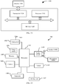
- the terminal device includes: a transceiver, a memory, and a processor.
- the transceiver, the memory, and the processor communicate with one another through an internal connection path.
- the memory is configured to store an instruction.
- the processor is configured to execute the instruction stored in the memory, to control the transceiver to receive and send signals.
- the processor executes the instruction stored in the memory, the processor is enabled to perform the method according to any one of the first aspect or the possible implementations of the first aspect.
- the network device includes: a transceiver, a memory, and a processor.
- the transceiver, the memory, and the processor communicate with one another through an internal connection path.
- the memory is configured to store an instruction.
- the processor is configured to execute the instruction stored in the memory, to control a receiver to receive a signal and control a transmitter to send a signal.
- the processor executes the instruction stored in the memory, the processor is enabled to perform the method according to any one of the second aspect or the possible implementations of the second aspect.
- a computer program product includes computer program code, and when the computer program code is run by a computer, the computer is enabled to perform the method according to any one of the first aspect or the possible implementations of the first aspect.
- a computer program product includes computer program code, and when the computer program code is run by a computer, the computer is enabled to perform the method according to any one of the second aspect or the possible implementations of the second aspect.
- a computer-readable medium comprises a computer program which, when executed by a computer, cause the computer to carry out the method according to any one of the first aspect or the possible implementations of the first aspect.
- a computer-readable medium comprises a computer program which, when executed by a computer, cause the computer to carry out the method according to any one of the second aspect or the possible implementations of the second aspect.
- a chip includes a processor, configured to read an instruction stored in a memory, wherein when the instruction is executed by the processor, cause the chip to carry out any one of the foregoing methods. Steps related to transmission and receiving should be understood as being performed by the processor by using a transceiver.
- a chip includes a processor, configured to read an instruction stored in a memory, to perform any one of the foregoing methods. Steps related to transmission and receiving should be understood as being performed by the processor by using a transceiver.
- a global system for mobile communications global system for mobile communication, GSM
- GSM global system for mobile communication
- CDMA code division multiple access
- WCDMA wideband code division multiple access
- general packet radio service general packet radio service, GPRS
- LTE long term evolution
- LTE frequency division duplex frequency division duplex
- TDD time division duplex
- UMTS universal mobile telecommunications system
- WiMAX worldwide interoperability for microwave access
- WiMAX worldwide interoperability for microwave access
- 5G future 5th-generation
- 5G new radio
- SCMA sparse code multiple access
- the technical solutions in the embodiments of this application may be applied to multicarrier transmission systems using the non-orthogonal multiple access technologies, for example, systems using non-orthogonal multiple access technologies of orthogonal frequency division multiplexing (orthogonal frequency division multiplexing, OFDM), filter bank multicarrier (filter bank multi carrier, FBMC), generalized frequency division multiplexing (generalized frequency division multiplexing, GFDM), and filtered-orthogonal frequency division multiplexing (filtered-OFDM, F-OFDM).
- OFDM orthogonal frequency division multiplexing
- filter bank multicarrier filter bank multi carrier
- FBMC filter bank multi carrier
- generalized frequency division multiplexing generalized frequency division multiplexing
- GFDM generalized frequency division multiplexing
- filtered-orthogonal frequency division multiplexing filtered-orthogonal frequency division multiplexing
- a terminal device in the embodiments of this application may communicate with one or more core networks by using a radio access network (radio access network, RAN), and the terminal device may be referred to as an access terminal, user equipment (user equipment, UE), a subscriber unit, a subscriber station, a mobile station, a mobile console, a remote station, a remote terminal, a mobile device, a user terminal, a terminal, a wireless communications device, a user agent, or a user apparatus.
- radio access network radio access network
- the access terminal may be a cellular phone, a cordless phone, a session initiation protocol (session initiation protocol, SIP) phone, a wireless local loop (wireless local loop, WLL) station, a personal digital assistant (personal digital assistant, PDA), a handheld device having a wireless communication function, a computing device, another processing device connected to a wireless modem, an in-vehicle device, a wearable device, a terminal device in a future 5G network, a terminal device in a future evolved public land mobile network (public land mobile network, PLMN), or the like.
- SIP session initiation protocol
- WLL wireless local loop
- PDA personal digital assistant
- a network device may be configured to communicate with the terminal device.
- the network device may be a base transceiver station (base transceiver station, BTS) in a GSM system or a CDMA system, or may be a NodeB (Node B, NB) in a WCDMA system, or may be an evolved NodeB (evolutional Node B, eNB or eNode B) in an LTE system.
- BTS base transceiver station
- NodeB Node B
- NB NodeB
- the network device may be a relay station, an access point, an in-vehicle device, a wearable device, a network side device in a future 5G network, or a network device in a future evolved PLMN.
- the embodiments of this application may be applied to the LTE system and a subsequent evolved system such as 5G system, or other wireless communications systems using various radio access technologies, for example, systems using access technologies such as code division multiple access, frequency division multiple access, time division multiple access, orthogonal frequency division multiple access, and single-carrier frequency division multiple access; and are particular applicable to scenarios in which channel information feedback is required and/or a second-level precoding technology is applied, for example, a wireless network applying a massive MIMO technology and a wireless network applying a distributed antenna technology.
- a multiple-input multiple-output (multiple-input multiple-output, MIMO) technology means that a plurality of transmit antennas and a plurality of receive antennas are respectively used for a transmit end device and a receive end device, so that a signal is transmitted and received by using the plurality of antennas of the transmit end device and the receive end device, thereby improving communication quality.
- MIMO multiple-input multiple-output
- a spatial resource can be fully used; and multiple-input multiple-output is implemented by using the plurality of antennas, so that a system channel capacity can be multiplied without an increase in a spectrum resource and antenna transmit power.
- MIMO may be classified into single-user multiple-input multiple-output (single-user MIMO, SU-MIMO) and multi-user multiple-input multiple-output (multi-user MIMO, MU-MIMO).
- single-user MIMO single-user MIMO
- multi-user MIMO multi-user MIMO
- SU-MIMO single-user multiple-input multiple-output
- MU-MIMO multi-user multiple-input multiple-output
- hundreds of antennas are arranged on the transmit end device according to a multi-user beamforming principle, to modulate respective beams for dozens of target receivers, and simultaneously transmit dozens of signals on a same frequency resource through spatial signal isolation. Therefore, according to the massive MIMO technology, spatial degree of freedom caused by a scaled antenna configuration can be fully used, thereby improving spectral efficiency.
- FIG. 1 is a schematic diagram of a communications system 100 used in an embodiment of this application.
- the communications system 100 includes a network device 102, and the network device 102 may include a plurality of antenna groups.
- Each antenna group may include one or more antennas.
- one antenna group may include antennas 104 and 106, another antenna group may include antennas 108 and 110, and an additional group may include antennas 112 and 114.
- two antennas are shown in FIG. 1 . However, more or fewer antennas may be used for each group.
- the network device 102 may additionally include a transmitter chain and a receiver chain.
- the transmitter chain and the receiver chain may both include a plurality of components related to signal sending and receiving, for example, a processor, a modulator, a multiplexer, a demodulator, a demultiplexer, or an antenna.
- the network device 102 may communicate with a plurality of terminal devices.
- the network device 102 may communicate with a terminal device 116 and a terminal device 122.
- the network device 102 may communicate with any quantity of terminal devices similar to the terminal device 116 or 122.
- the terminal devices 116 and 122 may be, for example, a cellular phone, a smartphone, a portable computer, a handheld communications device, a handheld computing device, a satellite radio apparatus, a global positioning system, a PDA, and/or any other suitable devices used for communication in the wireless communications system 100.
- the terminal device 116 communicates with the antennas 112 and 114.
- the antennas 112 and 114 send information to the terminal device 116 by using a forward link 118, and receive information from the terminal device 116 by using a reverse link 120.
- the terminal device 122 communicates with the antennas 104 and 106.
- the antennas 104 and 106 send information to the terminal device 122 by using a forward link 124, and receive information from the terminal device 122 by using a reverse link 126.
- the forward link 118 may use a frequency band different from that used by the reverse link 120; the forward link 124 may use a frequency band different from that used by the reverse link 126.
- the forward link 118 and the reverse link 120 may use a same frequency band, and the forward link 124 and the reverse link 126 may use a same frequency band.
- Each group of antennas and/or an area that is designed for communication is referred to as a sector of the network device 102.
- an antenna group may be designed to communicate with a terminal device in the sector within coverage of the network device 102.
- a transmit antenna of the network device 102 may improve signal-to-noise ratios of the forward links 118 and 124 through beamforming.
- the network device 102 sends, through beamforming, signals to the terminal devices 116 and 122 that are randomly distributed within the related coverage, less interference is caused to a mobile device in a neighboring cell.
- the network device 102 and the terminal device 116 or the terminal device 122 may be a sending apparatus for wireless communication and/or a receiving apparatus for wireless communication.
- the sending apparatus for wireless communication may encode the data for transmission.
- the sending apparatus for wireless communication may obtain a particular quantity of data bits to be sent to the receiving apparatus for wireless communication over a channel.
- the sending apparatus for wireless communication may generate, receive from another communications apparatus, or store in a memory, the particular quantity of data bits to be sent to the receiving apparatus for wireless communication over the channel.
- Such data bits may be included in a transport block or a plurality of transport blocks of the data, and the transport block may be segmented to generate a plurality of code blocks.
- the communications system 100 may be a public land mobile network PLMN, a device-to-device (device-to-device, D2D) network, a machine-to-machine (machine-to-machine, M2M) network, or another network.
- PLMN public land mobile network
- D2D device-to-device
- M2M machine-to-machine
- FIG. 1 is merely a simplified schematic diagram used as an example for ease of understanding.
- the network may further include another network device, not shown in FIG. 1 .
- Resource unit similar to an RB and an RB pair (RB pair) in an LTE standard.
- the resource unit may be used as a basic unit by a scheduling terminal for resource allocation, or may be used to describe an arrangement manner of a plurality of reference signals.
- the resource unit may include a plurality of subcarriers consecutive in frequency domain and one time interval (time interval, TI) in time domain. In different scheduling processes, the resource unit may have a same size or different sizes.
- the TI herein may be a transmission time interval (transmission time interval, TTI) in an LTE system, a symbol-level short TTI, a short TTI of a large subcarrier spacing in a high-frequency system, a slot or a mini-slot (mini-slot) in a 5G system, or the like. This is not limited in this application.
- one resource unit may include one or more RBs, one or more RB pairs, or the like; or may be half an RB or the like.
- the resource unit may alternatively be another time-frequency resource. This is not limited in this application.
- One RB pair includes 12 consecutive subcarriers in frequency domain and one subframe in time domain.
- a time-frequency resource including one subcarrier in frequency domain and one symbol in time domain is one resource element (resource element, RE), as shown in FIG. 2 .
- An RB pair in FIG. 2 includes 12 consecutive subcarriers (numbered from 0 to 11) in frequency domain and 14 symbols (numbered 0 to 13) in time domain.
- FIG. 2 a horizontal coordinate indicates the time domain, and a vertical coordinate indicates the frequency domain.
- "include” in this application indicates that accompanying drawings of a time domain resource are all described based on an example of the RB pair shown in FIG. 2 . A person skilled in the art may understand that in a specific implementation, this application is not limited thereto.
- a "symbol” in this application may include, but is not limited to, any one of the following: an orthogonal frequency division multiplexing (orthogonal frequency division multiplexing, OFDM) symbol, a universal filtered multi-carrier (universal filtered multicarrier, UFMC) symbol, a filter bank multicarrier (filter band multicarrier, FBMC) symbol, a generalized frequency-division multiplexing (generalized frequency-division multiplexing, GFDM) symbol, and the like.
- OFDM orthogonal frequency division multiplexing
- OFDM orthogonal frequency division multiplexing
- UFMC universal filtered multicarrier
- FBMC filter bank multicarrier
- GFDM generalized frequency-division multiplexing
- DMRS component pattern a DMRS pattern that can support a maximum quantity of ports on a specific quantity of consecutive symbols in one resource unit in time domain.
- a specific symbol position of the DMRS component pattern is not limited herein.
- the DMRS component pattern may be placed in front, or may be placed behind.
- a specific quantity of symbols of the DMRS component pattern is also not limited.
- the DMRS component pattern may occupy one symbol in time domain, or may occupy two symbols in time domain.
- a port multiplexing manner in the DMRS component pattern is not limited.
- the DMRS pattern includes at least one DMRS component pattern.
- one DMRS pattern may include only one DMRS component pattern, or may include a plurality of same DMRS component patterns, or may include a plurality of different DMRS component patterns. This is not limited in the embodiments of this application.
- the DMRS component pattern may be classified into the following two different types based on a time domain position of the DMRS component pattern in the resource unit.
- symbols included in one resource unit in time domain are continuously numbered by starting from 0, and subcarriers included in one resource unit in frequency domain are numbered by starting from 0.
- the RB pair may include symbols 0 to 13 in time domain, and may include subcarriers 0 to 11 in frequency domain.
- this application is not limited thereto.
- one resource unit may include symbols 1 to 14 in time domain, and may include subcarriers 1 to 12 in frequency domain.
- the DMRS may be mapped to at least one symbol in the resource unit.
- the at least one symbol may be a front symbol or a rear symbol in the resource unit.
- the front symbol is a symbol in a front position in a resource unit, for example, may correspond to a symbol before a symbol numbered 7 (namely, the seventh symbol) in FIG. 2 or the seventh symbol.
- the front symbol is specifically defined as, this is not limited in this application.
- the at least one symbol maybe the rear symbol.
- the rear symbol is a symbol after the symbol numbered 7 in FIG. 2 .
- the rear symbol is specifically defined as, this is not limited in this application.
- the plurality of symbols may be symbols of a same type or may be symbols of different types.
- the type includes the front symbol and the rear symbol.
- the plurality of symbols are all front symbols; or some of the plurality of symbols are front symbols, and the other symbols are rear symbols.
- the plurality of symbols may be consecutive or may be discrete.
- the plurality of symbols may be neighboring symbols or may be non-neighboring symbols. It may be understood that, in this application, some or all of the DMRSs may be mapped to the front symbols. In this way, a receiving device can more quickly complete receiving the DMRSs, to start data demodulation, and satisfy a requirement for quick data demodulation in NR.
- mapping rules between a DMRS and a time domain resource are schematically described in this application, and may be specifically presented by using a DMRS pattern (pattern).
- the foregoing mapping rule may be implemented by using a formula, a table, or another manner.
- the terminal device may learn of, according to a rule agreed with the network device or information used to indicate a time-frequency resource corresponding to a DMRS, the time-frequency resource corresponding to the DMRS.
- the network device may configure, for the terminal device by using radio resource control (radio resource control, RRC) signaling, a pattern of a DMRS located on a front symbol, and additionally configure, by using downlink control information (downlink control information, DCI), a position of a DMRS located on a rear symbol.
- RRC radio resource control
- the network device may further indicate a quantity of DMRSs by using indication information, and the terminal device selects a DMRS pattern corresponding to the quantity of DMRSs.
- the network device may alternatively directly configure a DMRS pattern by using RRC signaling. This is not limited in this application. How the terminal device obtains the DMRS from the time-frequency resource may be implemented by using a method in the prior art.
- a mapping type of a physical shared channel may include a first type and a second type, respectively referred to as a PDSCH (or PUSCH) mapping type A and a PDSCH (or PUSCH) mapping type B.
- the mapping type A and the mapping type B correspond to different resource mapping manners.
- the technical solutions provided in this application may be applied to a single-carrier transmission scenario or a multi-carrier transmission scenario; or may be applied to an uplink transmission scenario or a downlink transmission scenario.
- the technical solutions provided in this application may be applied to a broadcast/multicast physical downlink shared channel (broadcast/multicast physical downlink shared channel, broadcast/multicast PDSCH), a physical broadcast channel (physical broadcast channel, PBCH), or the like. This is not limited in the embodiments of this application.
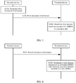
- FIG. 3 is a schematic flowchart of a resource indication method 300 according to an embodiment of this application.
- the method 300 may be applied to the communications system 100 shown in FIG. 1 , but this embodiment of this application is not limited thereto.
- a network device determines first indication information, where the first indication information is used to indicate a mapping type of a physical shared channel of demodulation reference signals, and the mapping type of the physical shared channel is a first type or a second type.
- the network device sends the first indication information to a terminal device, and correspondingly, the terminal device receives the first indication information sent by the network device.
- the terminal device determines time domain positions occupied by the DMRSs in a resource unit based on the mapping type of the physical shared channel and with reference to a position index of the last symbol occupied by the physical shared channel in the resource unit or a quantity of symbols occupied by the physical shared channel in the resource unit.
- the position index of the last symbol occupied by the physical shared channel in the resource unit corresponds to the first type, and the quantity of symbols occupied by the physical shared channel in the resource unit corresponds to the second type.
- the network device may first send, to the terminal device, the first indication information used to indicate the mapping type of the physical shared channel.
- the terminal device receives the first indication information, and may determine, based on the first indication information, whether the mapping type that is of the physical shared channel and that is configured by the network device for the terminal device is the first type or the second type. If the mapping type of the physical shared channel is the first type, the terminal device may determine, with reference to the position index of the last symbol occupied by the physical shared channel in the resource unit, the time domain positions occupied by DMRSs in the resource unit.
- the terminal device may determine, with reference to the quantity of symbols occupied by the physical shared channel in the resource unit, the time domain positions occupied by DMRSs in the resource unit.
- the first indication information may be carried in downlink control information (downlink control information, DCI).
- the first type corresponds to the position index of the last symbol occupied by the physical shared channel in the resource unit
- the second type corresponds to the quantity of symbols occupied by the physical shared channel in the resource unit.
- This correspondence may be predefined in a protocol, or may be configured by the network device for the terminal device by using signaling. This is not limited in this embodiment of this application.
- both the network device and the terminal device store DMRS configuration information, and the DMRS configuration information includes different time domain positions of the DMRSs in different mapping types of the physical shared channel.
- the network device configures the time domain positions of the DMRSs for the terminal device based on the DMRS configuration information, and notifies the terminal device by using the first indication information.
- the terminal device receives the first indication information, selects information corresponding to the mapping type of the physical shared channel from the DMRS configuration information based on the mapping type that is of the physical shared channel and that is indicated by the first indication information, and determines the time domain positions of the DMRSs in the resource unit with reference to a parameter corresponding to the mapping type of the physical shared channel.
- the DMRSs may be classified into uplink DMRSs and downlink DMRSs, and the physical shared channel may include a physical uplink shared channel (physical uplink shared channel, PUSCH) and a physical downlink shared channel (physical downlink shared channel, PDSCH).
- the position index of the last symbol occupied by the physical shared channel in the resource unit may also be referred to as the last symbol of the PUSCH, the last symbol of the PDSCH, the last symbol used for the PDSCH, or the last symbol used for the PUSCH ina slot.
- the quantity of symbols occupied by the physical shared channel in the resource unit may also be referred to as PUSCH duration in symbols, PDSCH duration in symbols, duration of the PUSCH transmission in symbols, or duration of the PDSCH transmission in symbols.
- PUSCH duration in symbols when the mapping type of the physical shared channel is the first type, the terminal device may use the last symbol of PUSCH; or when the mapping type of the physical shared channel is the second type, the terminal device may use the PUSCH duration in the symbols.
- the terminal device may use the last symbol of the PDSCH; or when the mapping type of the physical shared channel is the second type, the terminal device may use the PDSCH duration in the symbols.
- mapping types of the physical shared channel are configured to correspond to different parameters, and the network device sends, to the terminal device, the indication information used to indicate the mapping type of the physical shared channel, so that the terminal device can select the corresponding parameter based on the mapping type of the physical shared channel, to help the terminal device accurately determine the time domain positions occupied by DMRSs in the resource unit, thereby improving performance of data transmission between the network device and the terminal device.
- the DMRSs include a first DMRS and an additional DMRS; and the determining time domain positions occupied by DMRSs in a resource unit includes: determining, by the terminal device, a time domain position occupied by the additional DMRS in the resource unit based on the mapping type of the physical shared channel and with reference to the position index of the last symbol occupied by the physical shared channel in the resource unit or the quantity of symbols occupied by the physical shared channel in the resource unit.
- the DMRSs may include the first DMRS (namely, a front-loaded DMRS) and the additional DMRS (namely, the additional DMRS).
- a time domain position of the first DMRS is decoupled from the time domain position of the additional DMRS, and there is no association relationship between the time domain position of the first DMRS and the time domain position of the additional DMRS.
- the time domain position of the first DMRS may be predefined in a protocol, or may be configured by the network device for the terminal device by using signaling. This is not limited in this embodiment of this application.
- the terminal device only needs to determine the time domain position of the additional DMRS based on the mapping type of the physical shared channel and with reference to the parameter (the position index of the last symbol occupied by the physical shared channel in the resource unit or the quantity of symbols occupied by the physical shared channel in the resource unit) corresponding to the mapping type of the physical shared channel.
- the terminal device may determine the time domain positions of the DMRSs with reference to the time domain position of the first DMRS and the time domain position of the additional DMRS.
- the terminal device may determine the time domain position occupied by the additional DMRS in the resource unit based on the position index of the last symbol occupied by the physical shared channel in the resource unit and the first mapping relationship.
- additional DMRSs may be used to indicate different quantities of additional DMRSs, where for example, the quantity of additional DMRSs is 0, 1, 2, or 3; or may be used to indicate DMRSs having different actual quantities of symbols, where for example, the actual quantity of symbols of the DMRS is one symbol or two symbols; or may be used to indicate additional DMRSs in different positions. This is not limited in this embodiment of this application.
- the first mapping relationship may be implemented by using a formula, a table, or another manner, and may be specifically used to indicate the correspondence between the different position indexes and the different time domain positions.
- the first mapping relationship is included in the DMRS configuration information.
- the terminal device may select the first mapping relationship from the DMRS configuration information based on the mapping type of the physical shared channel, namely, the first type, and select the time domain position occupied by the additional DMRS in the resource unit from the first mapping relationship with reference to the position index of the last symbol occupied by the physical shared channel in the resource unit.
- this is not limited in this embodiment of this application.
- the mapping type of the physical shared channel is the second type; and the determining a time domain position occupied by the additional DMRS in the resource unit includes: determining, by the terminal device, the time domain position occupied by the additional DMRS in the resource unit based on at least the quantity of symbols occupied by the physical shared channel in the resource unit and a second mapping relationship, where the second mapping relationship is used to indicate a correspondence between different quantities of symbols occupied by physical shared channels in the resource unit and different time domain positions occupied by additional DMRSs in the resource unit.
- the terminal device may determine the time domain position occupied by the additional DMRS in the resource unit based on the quantity of symbols occupied by the physical shared channel in the resource unit and the second mapping relationship.
- the second mapping relationship may be implemented by using a formula, a table, or another manner, and may be specifically used to indicate the correspondence between the different quantities of symbols and the different time domain positions.
- the second mapping relationship is included in the DMRS configuration information.
- the terminal device may select the second mapping relationship from the DMRS configuration information based on the mapping type of the physical shared channel, namely, the second type, and select the time domain position occupied by the additional DMRS in the resource unit from the second mapping relationship with reference to the quantity of symbols occupied by the physical shared channel in the resource unit.
- this is not limited in this embodiment of this application.
- the method before the determining a time domain position occupied by the additional DMRS in the resource unit, the method further includes:
- the network device may further send, to the terminal device, the second indication information used to indicate the quantity of additional DMRSs and the third indication information used to indicate the actual quantity of symbols occupied by the first DMRS in the resource unit.
- the terminal device may determine the time domain position occupied by the additional DMRS in the resource unit based on information such as the mapping type of the physical shared channel, the parameter corresponding to the mapping type of the physical shared channel, the quantity of additional DMRSs, and the actual quantity of symbols occupied by the first DMRS in the resource unit.
- the quantity of additional DMRSs may be 0, 1, 2, or 3, and the actual quantity of symbols occupied by the first DMRS in the resource unit may be 1 or 2.
- the network device may configure different resource mapping manners for the terminal device. Therefore, there is also a correspondence between the time domain position occupied by the additional DMRS in the resource unit and parameters such as the quantity of additional DMRSs and the actual quantity of symbols occupied by the first DMRS in the resource unit.
- the DMRS configuration information may include a correspondence between different mapping types of physical shared channels, different quantities of additional DMRSs, different actual quantities of symbols occupied by the first DMRSs in the resource unit, and different time domain positions. However, this is not limited in this embodiment of this application.
- the second indication information may be carried in radio resource control (radio resource control, RRC) signaling.
- the third indication information may be indicated by using one piece of signaling or may be jointly indicated by using a plurality of pieces of signaling. This is not limited in this embodiment of this application.
- the network device may first indicate, to the terminal device by using RRC signaling, a maximum quantity of symbols occupied by the first DMRS in the resource unit. If the maximum quantity of symbols is 1, the actual quantity of symbols occupied by the first DMRS in the resource unit is inevitably 1 and does not need to be further indicated.
- the actual quantity of symbols occupied by the first DMRS in the resource unit may be 1 or 2, and the network device needs to further indicate, to the terminal device by using downlink control information (downlink control information, DCI), the actual quantity of symbols occupied by the first DMRS in the resource unit.
- DCI downlink control information
- a resource configuration method specifically includes: receiving demodulation reference signal (DMRS) configuration information, where the DMRS configuration information includes time domain positions of DMRSs in different mapping types of a physical shared channel, the mapping type of the physical shared channel is a first type or a second type, DMRS configuration information corresponding to the first type includes a position index of the last symbol occupied by the physical shared channel in a resource unit, and DMRS configuration information corresponding to the second type includes a quantity of symbols occupied by the physical shared channel in the resource unit; and storing the DMRS configuration information.
- DMRS demodulation reference signal
- the DMRS configuration information may be implemented by using a formula, a table, or another manner. Both the network device and the terminal device may store the DMRS configuration information, to subsequently configure the time domain positions of the DMRSs based on the DMRS configuration information.
- the network device sends first indication information to the terminal device by using DCI.
- the terminal device receives the DCI, determines, based on the first indication information, whether a mapping type of a current PUSCH is a PUSCH mapping type A or a PUSCH mapping type B, and further selects Table 1 or Table 2.
- time domain positions of DMRSs are defined relative to a start symbol position in a slot.
- a position l 0 of the first DMRS symbol in time domain may be configured to 2 (the third symbol of the slot) or 3 (the fourth symbol of the slot) by using higher layer signaling DL-DMRS-typeA-pos.
- time domain positions of DMRSs are defined relative to a start symbol position of a resource of a scheduled PUSCH.
- a position l 0 of the first DMRS symbol in time domain is the first symbol of the PUSCH, and has an index of 0 relative to a time domain position of the PUSCH.
- the network device may indicate an actual quantity of symbols of a front-loaded DMRS to the terminal device by using third indication information.
- the terminal device may determine, based on the actual quantity of symbols of the front-loaded DMRS, to select a DMRS location corresponding to a single-symbol DMRS or a double-symbol DMRS.
- the network device may configure a maximum quantity of symbols of the front-loaded DMRS by using RRC signaling (UL-DMRS-max-len).
- the network device may further configure the actual quantity of symbols of the front-loaded DMRS by using DCI signaling.
- the terminal device obtains, based on the RRC signaling or with reference to the RRC signaling and the DCI signaling, the current front-loaded DMRS being the single-symbol DMRS or the double-symbol DMRS.
- the network device may indicate a quantity of additional DMRSs to the terminal device by using second indication information. Specifically, the network device sends UL-DMRS-add-pos by using RRC signaling. The terminal device receives the RRC signaling to obtain the quantity of additional DMRSs, and selects a corresponding DMRS position set from a table.
- the network device may indicate a quantity of consecutive symbols of the PUSCH (PUSCH duration in symbols) and a start symbol position of the PUSCH to the terminal device by using DCI signaling.
- the terminal device receives the DCI signaling, and may obtain the PUSCH duration in the symbols or a position of the last symbol of the PUSCH (position of the last PUSCH symbols), and determines the final time domain positions of the DMRSs based on the mapping type of the PUSCH. Specifically, when the mapping type of the PUSCH is the PUSCH mapping type A, the terminal device determines the time domain positions of the DMRSs in Table 1 by using the position of the last PUSCH symbols.
- the terminal device determines the time domain positions of the DMRSs in Table 2 by using the PUSCH duration in the symbols. Further, the terminal device may map and send the DMRSs in the position.
- the terminal device may use a different sequence with reference to the foregoing signaling, provided that the time domain positions of the DMRSs can be determined.
- Table 1 Time domain positions of uplink DMRSs in the PUSCH mapping type A Position of last PUSCH symbol DM-RS positions l single-symbol DM-RS double-symbol DM-RS UL-DMRS-add-pos UL-DMRS-add-pos 0 1 2 3 0 1 2 3 ⁇ 7 l 0 - - l 0 - 8 l 0 l 0 , 7 - - l 0 - 9 l 0 l 0 , 9 l 0 , 6, 9 - l 0 l 0 , 8 10 l 0 l 0 , 9 l 0 , 6, 9 - l 0 l 0 , 8 11 l 0 0 , 9 l 0 , 6, 9 l 0 0 , 5, 8, 11 l 0 l 0 , 8 12 l 0 l 0 , 11 l 0 0 , 7, 11 l 0
- a position of a DMRS symbol may be represented by l
- the last symbol of the PUSCH in the slot is used in Table 1
- the quantity of consecutive symbols of the PUSCH is used in Table 2.
- UL-DMRS-add-pos may be equal to 3 in the mapping type A only.
- the position(s) of the DMRS symbols is given by l and the last OFDM symbol used for PUSCH in the slot according to Table 1 and the duration of PUSCH transmission in the symbols according to and Table 2 respectively.
- the case UL-DMRS-add-pos equal to 3 of PUSCH mapping type A is only supported when DL-DMRS-typeA-pos is equal to 2.
- the terminal device selects Table 1 and determines that the position of the last PUSCH symbol is 8, the actual quantity of symbols of the front-loaded DMRS is the single-symbol DMRS, and the quantity of additional DMRSs is 1. In this case, the terminal device may select a time domain position being 7 of the additional DMRS from Table 1.
- a specific DMRS pattern is shown in FIG. 5.
- FIG. 5 shows an example in which the front-loaded DMRS is located at 2 (the third symbol of the slot).
- the terminal device selects Table 1 and determines that the position of the last PUSCH symbol is 9, the actual quantity of symbols of the front-loaded DMRS is the single-symbol DMRS, and the quantity of additional DMRSs is 1. In this case, the terminal device may select a time domain position being 9 of the additional DMRS from Table 1.
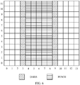
- a specific DMRS pattern is shown in FIG. 6.
- FIG. 6 shows an example in which the front-loaded DMRS is located at 3 (the fourth symbol of the slot).
- the terminal device selects Table 2 and determines that the PUSCH duration in the symbols is 9, the actual quantity of symbols of the front-loaded DMRS is the single-symbol DMRS, and the quantity of additional DMRSs is 2. In this case, the terminal device may select time domain positions being 3 and 6 of the additional DMRSs from Table 2.
- the configuration may be replaced with another DMRS position configuration. For example, only l 0 may be included, or a configuration in which a quantity of UL-DMRS-add-pos is decreased by 1 is used, or a DMRS beyond a PUSCH range may be punctured (puncture).
- Table 1 and Table 2 may be two independent tables, or may be combined into one table, or may be embedded into another table.
- a specific form of expression of the tables is not limited in this embodiment of this application.
- the network device sends first indication information to the terminal device by using DCI.
- the terminal device receives the DCI, determines, based on the first indication information, whether a mapping type of a current PDSCH is a PDSCH mapping type A or a PDSCH mapping type B, and further selects Table 3 or Table 4.
- time domain positions of DMRSs are defined relative to a start symbol position in a slot.
- a position l 0 of the first DMRS symbol in time domain may be configured to 2 (the third symbol of the slot) or 3 (the fourth symbol of the slot) by using higher layer signaling DL-DMRS-typeA-pos.
- time domain positions of DMRSs are defined relative to a start symbol position of a resource of a scheduled PDSCH.
- a position l 0 of the first DMRS symbol in time domain is the first symbol of the PDSCH, and has an index of 0 relative to a time domain position of the PDSCH.
- the network device may indicate a quantity of additional DMRSs to the terminal device by using second indication information. Specifically, the network device sends DL-DMRS-add-pos by using RRC signaling. The terminal device receives the RRC signaling to obtain the quantity of additional DMRSs, and selects a corresponding DMRS position set from a table.
- the network device may indicate an actual quantity of symbols of a front-loaded DMRS to the terminal device by using third indication information.
- the terminal device may determine, based on the actual quantity of symbols of the front-loaded DMRS, to select a DMRS location corresponding to a single-symbol DMRS or a double-symbol DMRS.
- the network device may configure a maximum quantity of symbols of the front-loaded DMRS by using RRC signaling (DL-DMRS-max-len).
- the network device may further configure the actual quantity of symbols of the front-loaded DMRS by using DCI signaling.
- the terminal device obtains, based on the RRC signaling or with reference to the RRC signaling and the DCI signaling, the current front-loaded DMRS being the single-symbol DMRS or the double-symbol DMRS.
- the network device may indicate a quantity of consecutive symbols of the PDSCH (PDSCH duration in symbols) and a start symbol position of the PDSCH to the terminal device by using DCI signaling.
- the terminal device receives the DCI signaling, to obtain the PDSCH duration in the symbols or a position of the last symbol of the PDSCH (position of the last PDSCH symbol), and determine the final time domain positions of the DMRSs based on the mapping type of the PDSCH. Specifically, when the mapping type of the PDSCH is the PDSCH mapping type A, the terminal device determines the time domain positions of the DMRSs in Table 1 by using the position of the last PDSCH symbol.
- the terminal device determines the time domain positions of the DMRSs in Table 2 by using the PDSCH duration in the symbols. Further, the terminal device may map and receive, in the position, the DMRSs sent by the network device.
- Table 3 Time domain positions of downlink DMRSs in the PDSCH mapping type A Position of last PDSCH symbol DM-RS positions l single-symbol DM-RS double-symbol DM-RS DL-DMRS-add-pos DL-DMRS-add-pos 0 1 2 3 0 1 2 3 ⁇ 7 l 0 - - l 0 - 8 l 0 l 0 , 7 - - l 0 - 9 l 0 l 0 , 9 l 0 , 6, 9 - l 0 l 0 , 8 10 l 0 l 0 , 9 l 0 , 6, 9 - l 0 l 0 , 8 11 l 0 l 0 , 9 l 0 , 6, 9 l 0 , 5, 8, 11 l 0 l 0 , 8 12 l 0 l 0 , 11 l 0 0 , 7, 11 l 0
- a position of a DMRS symbol may be represented by l
- the last symbol of the PDSCH in the slot is used in Table 3
- the quantity of consecutive symbols of the PDSCH is used in Table 4.
- DL-DMRS-typeA-pos is equal to 2
- DL-DMRS-add-pos may be equal to 3 in the PDSCH mapping type A only.
- the position(s) of the DMRS symbols is given by l and the last OFDM symbol used for the PDSCH in the slot according to Table 3 and the duration of PDSCH transmission in symbols according to Table 4 respectively.
- the case DL-DMRS-add-pos equal to 3 of PDSCH mapping type A is only supported when DL-DMRS-typeA-pos is equal to 2.
- the terminal device selects Table 3 and determines that the position of last PDSCH symbol is 10, the actual quantity of symbols of the front-loaded DMRS is the single-symbol DMRS, and the quantity of additional DMRSs is 2. In this case, the terminal device may select time domain positions being 6 and 9 of the additional DMRSs from Table 3.
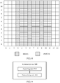
- FIG. 7 shows an example in which the front-loaded DMRS is located at 3 (the fourth symbol of the slot).
- the terminal device selects Table 3 and determines that the position of last PDSCH symbol is 11, the actual quantity of symbols of the front-loaded DMRS is the single-symbol DMRS, and the quantity of additional DMRSs is 2. In this case, the terminal device may select time domain positions being 6 and 9 of the additional DMRSs from Table 3.
- FIG. 8 shows an example in which the front-loaded DMRS is located at 3 (the fourth symbol of the slot).
- the terminal device selects Table 4 and determines that the PDSCH duration in the symbols is 7, the actual quantity of symbols of the front-loaded DMRS is the single-symbol DMRS, and the quantity of additional DMRSs is 1. In this case, the terminal device may select a time domain position being 4 of the additional DMRS from Table 4.
- Table 1 and Table 2 indicate that the configuration is not supported, and in a specific implementation, may be processed in a manner similar to that in Table 1 and Table 2. It should be further understood that, Table 3 and Table 4 may be two independent tables, or may be combined into one table, or may be embedded into another table. Table 1 to Table 4 may alternatively be combined into one table. A specific form of expression of the tables is not limited in this embodiment of this application.
- FIG. 4 is a schematic flowchart of another resource indication method 400 according to an example of this application.
- the method 400 may be applied to the communications system 100 shown in FIG. 1 , but this example of this application is not limited thereto.
- a network device sends fourth indication information to a terminal device, and correspondingly, the terminal device receives the fourth indication information sent by the network device, where the fourth indication information is used to indicate a mapping type of a physical shared channel of demodulation reference signals and a quantity of symbols occupied by the physical shared channel in a resource unit, and the mapping type of the physical shared channel is a first type or a second type.
- the terminal device determines a time domain position occupied by an additional DMRS in the DMRSs in the resource unit based on the mapping type of the physical shared channel, the quantity of symbols occupied by the physical shared channel in the resource unit, and a time domain position occupied by a first DMRS in the DMRSs in the resource unit.
- the network device may send, to the terminal device, the fourth indication information used to indicate the mapping type of the physical shared channel and the quantity of symbols occupied by the physical shared channel in the resource unit.
- the terminal device receives the fourth indication information, and may determine the time domain position occupied by the additional DMRS in the resource unit based on the mapping type of the physical shared channel and the quantity of symbols occupied by the physical shared channel in the resource unit and with reference to the time domain position occupied by the first DMRS in the resource unit, namely, l 0 .
- the fourth indication information may be carried in downlink control information (downlink control information, DCI).
- the mapping type of the physical shared channel may be the first type or the second type, and parameters corresponding to the first type and the second type are both the quantity of symbols (duration) occupied by the physical shared channel in the resource unit.
- a specific chronological order of determining the time domain position of the additional DMRS by the terminal device is not limited in this example of this application. For example, the terminal device may first perform selection based on the mapping type of the physical shared channel, then perform selection based on the duration of the physical shared channel, and at last, select the final time domain position of the additional DMRS based on l 0 .
- the terminal device may first perform selection based on l 0 and then based on the mapping type of the physical shared channel, and finally select the final time domain position of the additional DMRS based on the duration of the physical shared channel.
- the terminal device may first perform selection based on l 0 and then based on the mapping type of the physical shared channel, and finally select the final time domain position of the additional DMRS based on the duration of the physical shared channel.
- both the network device and the terminal device store DMRS configuration information, and the DMRS configuration information includes time domain positions of the DMRSs in different mapping types of the physical shared channel.
- the network device configures time domain positions of the DMRSs for the terminal device based on the DMRS configuration information, and notifies the terminal device by using the fourth indication information.
- the terminal device receives the fourth indication information, and determines the time domain positions of the DMRSs in the resource unit based on the mapping type of the physical shared channel and the duration of the physical shared channel that are indicated by the fourth indication information and with reference to the time domain position of the first DMRS.
- the DMRSs may be classified into uplink DMRSs and downlink DMRSs, and the physical shared channel may include a physical uplink shared channel (physical uplink shared channel, PUSCH) and a physical downlink shared channel (physical downlink shared channel, PDSCH).
- the quantity of symbols occupied by the physical shared channel in the resource unit may also be referred to as PUSCH duration in symbols or PDSCH duration in symbols. If the DMRSs are uplink DMRSs, the terminal device may use the PUSCH duration in the symbols. If the DMRSs are downlink DMRSs, the terminal device may use the PDSCH duration in the symbols.
- the terminal device determines the time domain position of the additional DMRS based on the indication information that is sent by the network device and that is used to indicate the mapping type of the physical shared channel and the quantity of symbols occupied by the physical shared channel in the resource unit and with reference to the time domain position of the first DMRS, to help accurately determine the time domain positions occupied by DMRSs in the resource unit, thereby improving performance of data transmission between the network device and the terminal device.
- the method before the determining a time domain position occupied by an additional DMRS in the DMRSs in the resource unit, the method further includes:
- the time domain position l 0 occupied by the first DMRS in the resource unit may be predefined in a protocol, or may be configured by the network device for the terminal device by using signaling. This is not limited in this example of this application.
- the network device may send the fifth indication information to the terminal device to indicate l 0 .
- the terminal device may determine the time domain position occupied by the additional DMRS in the resource unit based on the quantity of symbols occupied by the physical shared channel in the resource unit, the time domain position occupied by the first DMRS in the resource unit, and the third mapping relationship.
- the third mapping relationship may be implemented by using a formula, a table, or another manner, and may be specifically used to indicate the correspondence between the different quantities of symbols and the different time domain positions.
- the third mapping relationship is included in the DMRS configuration information.
- the terminal device may select the third mapping relationship from the DMRS configuration information based on the mapping type of the physical shared channel, namely, the first type, and select the time domain position occupied by the additional DMRS in the resource unit from the third mapping relationship with reference to the quantity of symbols occupied by the physical shared channel in the resource unit and the time domain position occupied by the first DMRS in the resource unit.
- this is not limited in this example of this application.
- the terminal device may determine the time domain position occupied by the additional DMRS in the resource unit based on the quantity of symbols occupied by the physical shared channel in the resource unit, the time domain position occupied by the first DMRS in the resource unit, and the fourth mapping relationship.
- the fourth mapping relationship may be implemented by using a formula, a table, or another manner, and may be specifically used to indicate the correspondence between the different quantities of symbols and the different time domain positions.
- the fourth mapping relationship is included in the DMRS configuration information.
- the terminal device may select the fourth mapping relationship from the DMRS configuration information based on the mapping type of the physical shared channel, namely, the second type, and select the time domain position occupied by the additional DMRS in the resource unit from the fourth mapping relationship with reference to the quantity of symbols occupied by the physical shared channel in the resource unit and the time domain position occupied by the first DMRS in the resource unit.
- this is not limited in this example of this application.
- the method before the determining a time domain position occupied by an additional DMRS in the DMRSs in the resource unit, the method further includes:
- the network device may further send, to the terminal device, the sixth indication information used to indicate the quantity of additional DMRSs and the seventh indication information used to indicate the actual quantity of symbols occupied by the first DMRS in the resource unit.
- the terminal device may determine the time domain position occupied by the additional DMRS in the resource unit based on information such as the mapping type of the physical shared channel, the quantity of symbols occupied by the physical shared channel in the resource unit, the quantity of additional DMRSs, and the actual quantity of symbols occupied by the first DMRS in the resource unit.
- the quantity of additional DMRSs may be 0, 1, 2, or 3, and the actual quantity of symbols occupied by the first DMRS in the resource unit may be 1 or 2.
- the network device may configure different resource mapping manners for the terminal device. Therefore, there is also a correspondence between the time domain position occupied by the additional DMRS in the resource unit and parameters such as the quantity of additional DMRSs and the actual quantity of symbols occupied by the first DMRS in the resource unit.
- the DMRS configuration information may include a correspondence between different mapping types of physical shared channels, different quantities of additional DMRSs, different actual quantities of symbols occupied by the first DMRSs in the resource unit, and different time domain positions. However, this is not limited in this example of this application.
- the sixth indication information may be carried in radio resource control (radio resource control, RRC) signaling.
- the seventh indication information may be indicated by using one piece of signaling or may be jointly indicated by using a plurality of pieces of signaling. This is not limited in this example of this application.
- the network device may first indicate, to the terminal device by using RRC signaling, a maximum quantity of symbols occupied by the first DMRS in the resource unit. If the maximum quantity of symbols is 1, the actual quantity of symbols occupied by the first DMRS in the resource unit is inevitably 1 and does not need to be further indicated.
- the actual quantity of symbols occupied by the first DMRS in the resource unit may be 1 or 2, and the network device needs to further indicate, to the terminal device by using downlink control information (downlink control information, DCI), the actual quantity of symbols occupied by the first DMRS in the resource unit.
- DCI downlink control information
- the resource configuration method specifically includes: receiving demodulation reference signal (DMRS) configuration information, where DMRSs include a first DMRS and an additional DMRS, the DMRS configuration information includes time domain positions that are of additional DMRSs and that correspond to different time domain positions of the first DMRSs in different mapping types of a physical shared channel, and the mapping types of the physical shared channel include a first type and a second type; and storing the DMRS configuration information.
- DMRS demodulation reference signal
- the DMRS configuration information may be implemented by using a formula, a table, or another manner. Both the network device and the terminal device may store the DMRS configuration information, to subsequently configure the time domain positions of the DMRSs based on the DMRS configuration information.
- the network device sends seventh indication information to the terminal device by using RRC signaling, to indicate an actual quantity of symbols of a front-loaded DMRS.
- the terminal device receives the RRC signaling, and selects, by using the seventh indication information, Table 5 corresponding to a single-symbol DMRS or Table 6 corresponding to a double-symbol DMRS.
- the network device may configure a maximum quantity of symbols of the front-loaded DMRS by using RRC signaling (UL-DMRS-max-len).
- the network device may further configure the actual quantity of symbols of the front-loaded DMRS by using DCI signaling.
- the terminal device obtains, based on the RRC signaling or with reference to the RRC signaling and the DCI signaling, the current front-loaded DMRS being the single-symbol DMRS or the double-symbol DMRS, and further determines to select Table 5 corresponding to the single-symbol DMRS or Table 6 corresponding to the double-symbol DMRS.
- the network device sends fourth indication information to the terminal device by using DCI.
- the terminal device receives the DCI, determines, based on the fourth indication information, whether a mapping type of a current PUSCH is a PUSCH mapping type A or a PUSCH mapping type B, and selects a corresponding column from the table.
- a mapping type of a current PUSCH is a PUSCH mapping type A or a PUSCH mapping type B
- selects a corresponding column from the table For the PUSCH mapping type A, time domain positions of DMRSs are defined relative to a start symbol position in a slot. In this case, a position l 0 of the first DMRS symbol in time domain may be configured to 2 (the third symbol of the slot) or 3 (the fourth symbol of the slot) by using higher layer signaling DL-DMRS-typeA-pos.
- time domain positions of DMRSs are defined relative to a start symbol position of a resource of a scheduled PUSCH.
- a position l 0 of the first DMRS symbol in time domain is the first symbol of the PUSCH, and has an index of 0 relative to a time domain position of the PUSCH.
- the network device may indicate a quantity of additional DMRSs to the terminal device by using sixth indication information. Specifically, the network device sends UL-DMRS-add-pos by using RRC signaling. The terminal device receives the RRC signaling to obtain the quantity of additional DMRSs, and selects a corresponding column (a DMRS position set) from the table.
- the network device may indicate a quantity of consecutive symbols of the PUSCH (PUSCH duration in symbols) and a start symbol position of the PUSCH to the terminal device by using DCI signaling.
- the terminal device receives the DCI signaling, to obtain the PUSCH duration in the symbols, and determines the final time domain positions of the DMRSs with reference to a specific value of the position l 0 of the front-loaded DMRS. Further, the terminal device may map and send the DMRSs in the position.
- the terminal device may use a different sequence with reference to the foregoing signaling, provided that the time domain positions of the DMRSs can be determined.
- a position of a DMRS symbol may be represented by l , and the quantity of consecutive symbols of the PUSCH is used in both Table 5 and Table 6.
- UL-DMRS-add-pos may be equal to 3.
- the position(s) of the DMRS symbols is given by l and the duration of the PUSCH transmission in the symbols according to Table 5 and 6.
- the case UL-DMRS-add-pos equal to 3 is only supported when DL-DMRS-typeA-pos is equal to 2.
- a specific DMRS pattern is shown in FIG. 5 .
- a specific DMRS pattern is shown in FIG. 6 .
- the configuration may be replaced with another DMRS position configuration.
- l 0 may be included, or a configuration in which a quantity of UL-DMRS-add-pos is decreased by 1 is used, or a DMRS beyond a PUSCH range may be punctured (puncture).
- PUSCH duration in the symbols 9
- corresponding "-" may be separately replaced with "l 0 ", "l 0 , 6, 9", or "l 0 , 5, 8" by using the foregoing method.
- this is not limited in this example of this application.
- Table 5 and Table 6 may be two independent tables, or may be combined into one table, or may be embedded into another table.
- a specific form of expression of the tables is not limited in this example of this application.
- the network device sends seventh indication information to the terminal device by using RRC signaling, to indicate an actual quantity of symbols of a front-loaded DMRS.
- the terminal device receives the RRC signaling, and selects, by using the seventh indication information, Table 7 corresponding to a single-symbol DMRS or Table 8 corresponding to a double-symbol DMRS.
- the network device may configure a maximum quantity of symbols of the front-loaded DMRS by using RRC signaling (DL-DMRS-max-len).
- the network device may further configure the actual quantity of symbols of the front-loaded DMRS by using DCI signaling.
- the terminal device obtains, based on the RRC signaling or with reference to the RRC signaling and the DCI signaling, the current front-loaded DMRS being the single-symbol DMRS or the double-symbol DMRS, and further determines to select Table 7 corresponding to the single-symbol DMRS or Table 8 corresponding to the double-symbol DMRS.
- the network device sends fourth indication information to the terminal device by using DCI.
- the terminal device receives the DCI, determines, based on the fourth indication information, whether a mapping type of a current PDSCH is a PDSCH mapping type A or a PDSCH mapping type B, and selects a corresponding column from the table.
- a mapping type A time domain positions of DMRSs are defined relative to a start symbol position in a slot.
- a position l 0 of the first DMRS symbol in time domain may be configured to 2 (the third symbol of the slot) or 3 (the fourth symbol of the slot) by using higher layer signaling DL-DMRS-typeA-pos.
- time domain positions of DMRSs are defined relative to a start symbol position of a resource of a scheduled PUSCH.
- a position l 0 of the first DMRS symbol in time domain is the first symbol of the PUSCH, and has an index of 0 relative to a time domain position of the PUSCH.
- the network device may indicate a quantity of additional DMRSs to the terminal device by using sixth indication information. Specifically, the network device sends DL-DMRS-add-pos by using RRC signaling. The terminal device receives the RRC signaling to obtain the quantity of additional DMRSs, and selects a corresponding column (a DMRS position set) from the table.
- the network device may indicate a quantity of consecutive symbols of the PDSCH (PDSCH duration in symbols) and a start symbol position of the PDSCH to the terminal device by using DCI signaling.
- the terminal device receives the DCI signaling, to obtain the PDSCH duration in the symbols, and determines the final time domain positions of the DMRSs with reference to a specific value of the position l 0 of the front-loaded DMRS. Further, the terminal device may receive, in the position, the DMRSs sent by the network device.
- the terminal device may use a different sequence with reference to the foregoing signaling, provided that the time domain positions of the DMRSs can be determined.
- a position of DMRS symbols may be represented by l , and the quantity of consecutive symbols of the PDSCH is used in both Table 7 and Table 8.
- DL-DMRS-typeA-pos when DL-DMRS-typeA-pos is equal to 2, DL-DMRS-add-pos may be equal to 3.
- the position(s) of the DMRS symbols is given by l and duration of PDSCH transmission in symbols to Tables 7 and 8. The case DL-DMRS-add-pos equal to 3 is only supported when DL-DMRS-typeA-pos is equal to 2.
- the terminal device may select time domain positions being 6 and 9 of the additional DMRSs from Table 7.
- a specific DMRS pattern is shown in FIG. 7 .
- the terminal device may select time domain positions being 6 and 9 of the additional DMRSs from Table 8.
- a specific DMRS pattern is shown in FIG. 8 .
- Table 7 and Table 8 indicate that the configuration is not supported, and in a specific implementation, may be processed in a manner similar to that in Table 5 and Table 6. It should be further understood that, Table 7 and Table 8 may be two independent tables, or may be combined into one table, or may be embedded into another table. Table 5 to Table 8 may alternatively be combined into one table. A specific form of expression of the tables is not limited in this example of this application.
- the resource indication method in the examples of this application is described in detail above with reference to FIG. 1 to FIG. 8 , and a terminal device and a network device in the examples of this application are described in detail below with reference to FIG. 9 to FIG. 14 .
- FIG. 9 shows a terminal device 900 according to an example of this application.
- the terminal device 900 includes:
- the DMRSs include a first DMRS and an additional DMRS.
- the determining unit 920 is specifically configured to determine a time domain position occupied by the additional DMRS in the resource unit based on the mapping type of the physical shared channel and with reference to the position index of the last symbol occupied by the physical shared channel in the resource unit or the quantity of symbols occupied by the physical shared channel in the resource unit.
- the mapping type of the physical shared channel is the first type.
- the determining unit 920 is specifically configured to determine the time domain position occupied by the additional DMRS in the resource unit based on at least the position index of the last symbol occupied by the physical shared channel in the resource unit and a first mapping relationship, where the first mapping relationship is used to indicate a correspondence between different position indexes of the last symbols of physical shared channels in the resource unit and different time domain positions occupied by additional DMRSs in the resource unit.
- the mapping type of the physical shared channel is the second type.
- the determining unit 920 is specifically configured to determine the time domain position occupied by the additional DMRS in the resource unit based on at least the quantity of symbols occupied by the physical shared channel in the resource unit and a second mapping relationship, where the second mapping relationship is used to indicate a correspondence between different quantities of symbols occupied by physical shared channels in the resource unit and different time domain positions occupied by additional DMRSs in the resource unit.
- the receiving unit 910 is further configured to: before the time domain position occupied by the additional DMRS in the resource unit is determined, receive second indication information sent by the network device, where the second indication information is used to indicate a quantity of additional DMRSs; and receive third indication information sent by the network device, where the third indication information is used to indicate an actual quantity of symbols occupied by the first DMRS in the resource unit.
- the determining unit 920 is specifically configured to determine the time domain position occupied by the additional DMRS in the resource unit based on the mapping type of the physical shared channel, the quantity of additional DMRSs, and the actual quantity of symbols occupied by the first DMRS in the resource unit and with reference to the position index of the last symbol occupied by the physical shared channel in the resource unit or the quantity of symbols occupied by the physical shared channel in the resource unit.
- the terminal device 900 herein is presented in a form of functional units.
- the term "unit" herein may refer to an application-specific integrated circuit (application-specific integrated circuit, ASIC), an electronic circuit, a processor (for example, a shared processor, a proprietary processor, or a packet processor) configured to perform one or more software or firmware programs, a combined logic circuit, and/or another appropriate component supporting the described function.
- ASIC application-specific integrated circuit
- processor for example, a shared processor, a proprietary processor, or a packet processor
- the terminal device 900 may be specifically the terminal device in the foregoing embodiments.
- the terminal device 900 may be configured to perform each procedure and/or step corresponding to the terminal device in the foregoing method embodiment 300. To avoid repetition, details are not described herein again.
- the receiving unit 910 is further configured to receive demodulation reference signal (DMRS) configuration information, where the DMRS configuration information includes time domain positions of the DMRSs in different mapping types of the DMRSs, the mapping type of the physical shared channel is the first type or the second type, DMRS configuration information corresponding to the first type includes the position index of the last symbol occupied by the physical shared channel in the resource unit, and DMRS configuration information corresponding to the second type includes the quantity of symbols occupied by the physical shared channel in the resource unit.
- the terminal device 900 further includes a storage unit, configured to store the DMRS configuration information.
- FIG. 10 shows a network device 1000 according to an embodiment of this application.
- the network device 1000 includes:
- the DMRSs include a first DMRS and an additional DMRS.
- the sending unit 1020 is further configured to: send second indication information to the terminal device, where the second indication information is used to indicate a quantity of additional DMRSs; and send third indication information to the terminal device, where the third indication information is used to indicate an actual quantity of symbols occupied by the first DMRS in the resource unit.
- the network device 1000 herein is presented in a form of functional units.
- the term "unit" herein may refer to an application-specific integrated circuit (application-specific integrated circuit, ASIC), an electronic circuit, a processor (for example, a shared processor, a proprietary processor, or a packet processor) configured to perform one or more software or firmware programs, a combined logic circuit, and/or another appropriate component supporting the described function.
- ASIC application-specific integrated circuit
- processor for example, a shared processor, a proprietary processor, or a packet processor
- the network device 1000 may be specifically the network device in the foregoing embodiments.
- the network device 1000 may be configured to perform each procedure and/or step corresponding to the network device in the foregoing method embodiment 300. To avoid repetition, details are not described herein again.
- the network device further includes: a receiving unit, configured to receive demodulation reference signal (DMRS) configuration information, where the DMRS configuration information includes time domain positions of the DMRSs in different mapping types of the DMRSs, the mapping type of the physical shared channel is the first type or the second type, DMRS configuration information corresponding to the first type includes the position index of the last symbol occupied by the physical shared channel in the resource unit, and DMRS configuration information corresponding to the second type includes the quantity of symbols occupied by the physical shared channel in the resource unit; and a storage unit, configured to store the DMRS configuration information.
- DMRS demodulation reference signal
- FIG. 11 shows another terminal device 1100 according to an embodiment of this application.
- the terminal device 1100 includes:
- the receiving unit 1110 is further configured to: before the time domain position occupied by the additional DMRS in the DMRSs in the resource unit is determined, receive fifth indication information sent by the network device, where the fifth indication information is used to indicate the time domain position occupied by the first DMRS in the resource unit.
- the mapping type of the physical shared channel is the first type.
- the determining unit 1120 is specifically configured to determine the time domain position occupied by the additional DMRS in the resource unit based on the quantity of symbols occupied by the physical shared channel in the resource unit, the time domain position occupied by the first DMRS in the resource unit, and a third mapping relationship, where the third mapping relationship is used to indicate a correspondence between different quantities of symbols occupied by physical shared channels in the resource unit, different time domain positions occupied by the first DMRSs in the resource unit, and different time domain positions occupied by additional DMRSs in the resource unit.
- the mapping type of the physical shared channel is the second type.
- the determining unit 1120 is specifically configured to determine the time domain position occupied by the additional DMRS in the resource unit based on the quantity of symbols occupied by the physical shared channel in the resource unit, the time domain position occupied by the first DMRS in the resource unit, and a fourth mapping relationship, where the fourth mapping relationship is used to indicate a correspondence between different quantities of symbols occupied by physical shared channels in the resource unit, different time domain positions occupied by the first DMRSs in the resource unit, and different time domain positions occupied by additional DMRSs in the resource unit.
- the receiving unit 1110 is further configured to: before the time domain position occupied by the additional DMRS in the DMRSs in the resource unit is determined, receive sixth indication information sent by the network device, where the sixth indication information is used to indicate a quantity of additional DMRSs; and receive seventh indication information sent by the network device, where the seventh indication information is used to indicate an actual quantity of symbols occupied by the first DMRS in the resource unit.
- the determining unit 1120 is specifically configured to determine the time domain position occupied by the additional DMRS in the resource unit based on the mapping type of the physical shared channel, the quantity of symbols occupied by the physical shared channel in the resource unit, the time domain position occupied by the first DMRS in the resource unit, the quantity of additional DMRSs, and the actual quantity of symbols occupied by the first DMRS in the resource unit.
- the terminal device 1100 herein is presented in a form of functional units.
- the term "unit" herein may refer to an application-specific integrated circuit (application-specific integrated circuit, ASIC), an electronic circuit, a processor (for example, a shared processor, a proprietary processor, or a packet processor) configured to perform one or more software or firmware programs, a combined logic circuit, and/or another appropriate component supporting the described function.
- ASIC application-specific integrated circuit
- processor for example, a shared processor, a proprietary processor, or a packet processor
- the terminal device 1100 may be specifically the terminal device in the foregoing embodiments.
- the terminal device 1100 may be configured to perform each procedure and/or step corresponding to the terminal device in the foregoing method embodiment 400. To avoid repetition, details are not described herein again.
- the receiving unit 1110 is further configured to receive demodulation reference signal (DMRS) configuration information of a, where the DMRSs include the first DMRS and the additional DMRS, the DMRS configuration information includes time domain positions that are of additional DMRSs and that correspond to different time domain positions of the first DMRSs in different mapping types of the physical shared channel, and the mapping types of the physical shared channel include the first type and the second type.
- the terminal device 1100 further includes a storage unit, configured to store the DMRS configuration information.
- FIG. 12 shows another terminal device 1200 according to an embodiment of this application.
- the terminal device 1200 includes a processor 1210, a transceiver 1220, and a memory 1230.
- the processor 1210, the transceiver 1220, and the memory 1230 communicate with one another through an internal connection path.
- the memory 1230 is configured to store an instruction.
- the processor 1210 is configured to execute the instruction stored in the memory 1230, to control the transceiver 1220 to send a signal and/or receive a signal.
- the processor 1201 When the program instruction stored in the memory 1203 is executed by the processor 1201, the processor 1201 is configured to: receive, by using the transceiver 1220, first indication information sent by a network device, where the first indication information is used to indicate a mapping type of a physical shared channel, and the mapping type of the physical shared channel is a first type or a second type; and determine time domain positions occupied by DMRSs in a resource unit based on the mapping type of the physical shared channel and with reference to a position index of the last symbol occupied by the physical shared channel in the resource unit or a quantity of symbols occupied by the physical shared channel in the resource unit, where the position index of the last symbol occupied by the physical shared channel in the resource unit corresponds to the first type, and the quantity of symbols occupied by the physical shared channel in the resource unit corresponds to the second type.
- the memory 1230 stores DMRS configuration information, where the DMRS configuration information includes time domain positions of DMRSs in different mapping types of the DMRSs, the mapping type of the physical shared channel is a first type or a second type, DMRS configuration information corresponding to the first type includes a position index of the last symbol occupied by the physical shared channel in a resource unit, and DMRS configuration information corresponding to the second type includes a quantity of symbols occupied by the physical shared channel in the resource unit.
- the processor 1201 and the memory 1203 may be combined into one processing apparatus, and the processor 1201 is configured to execute program code stored in the memory 1203, to implement the foregoing functions.
- the memory 1203 may alternatively be integrated into the processor 1201 or independent of the processor 1201.
- the terminal device 1200 may further include an antenna 1204, configured to send, by using a radio signal, uplink data or uplink control signaling that is output by the transceiver 1202.
- the terminal device 1200 may be specifically the terminal device in the foregoing embodiment 300, and may be configured to perform each step and/or procedure corresponding to the terminal device in the foregoing method embodiment 300.
- the memory 1203 may include a read-only memory and a random access memory, and provide an instruction and data to the processor. Apart of the memory may further include a non-volatile random access memory.
- the memory may further store information about a device type.
- the processor 1201 may be configured to execute the instruction stored in the memory, and when the processor 1201 executes the instruction stored in the memory, the processor 1201 is configured to perform each step and/or procedure corresponding to the terminal device in the foregoing method embodiment.
- the processor 1201 may be configured to perform an action that is implemented inside the terminal and that is described in the foregoing method embodiment, and the transceiver 1202 may be configured to perform an action of receiving from the network device by the terminal that is described in the foregoing method embodiment.
- the transceiver 1202 may be configured to perform an action of receiving from the network device by the terminal that is described in the foregoing method embodiment.
- the terminal device 1200 may further include a power supply 1206, configured to provide a power source for various components or circuits in the terminal device 1200.
- the terminal device 1200 may further include one or more of an input unit 1206, a display unit 1207, an audio circuit 1208, a camera 12012, and a sensor 1210.
- the audio circuit may further include a speaker 12082, a microphone 12084, and the like.
- FIG. 13 shows another network device 1300 according to an embodiment of this application.
- the network device 1300 includes a processor 1310, a transceiver 1320, and a memory 1330.
- the processor 1310, the transceiver 1320, and the memory 1330 communicate with one another through an internal connection path.
- the memory 1330 is configured to store an instruction.
- the processor 1310 is configured to execute the instruction stored in the memory 1330, to control the transceiver 1320 to send a signal and/or receive a signal.
- the processor 1310 When the program instruction stored in the memory 1330 is executed by the processor 1310, the processor 1310 is configured to: determine first indication information, where the first indication information is used to indicate a mapping type of a physical shared channel of demodulation reference signals, and the mapping type of the physical shared channel is a first type or a second type; and send the first indication information to a terminal device by using the transceiver 1320, where a position index of the last symbol occupied by the physical shared channel in a resource unit corresponds to the first type, and a quantity of symbols occupied by the physical shared channel in the resource unit corresponds to the second type.
- the memory 1330 stores DMRS configuration information, where the DMRS configuration information includes time domain positions of DMRSs in different mapping types of the DMRSs, the mapping type of the physical shared channel is a first type or a second type, DMRS configuration information corresponding to the first type includes a position index of the last symbol occupied by the physical shared channel in a resource unit, and DMRS configuration information corresponding to the second type includes a quantity of symbols occupied by the physical shared channel in the resource unit.
- the processor 1310 and the memory 1330 may be combined into one processing apparatus, and the processor 1310 is configured to execute program code stored in the memory 1330, to implement the foregoing functions.
- the memory 1330 may alternatively be integrated into the processor 1310 or independent of the processor 1310.
- the network device 1300 may further include an antenna 1340, configured to send, by using a radio signal, downlink data or downlink control signaling that is output by the transceiver 1320.
- the network device 1300 may be specifically the network device in the foregoing embodiment 300, and may be configured to perform each step and/or procedure corresponding to the network device in the foregoing method embodiment 300.
- the memory 1330 may include a read-only memory and a random access memory, and provide an instruction and data to the processor. Apart of the memory may further include a non-volatile random access memory.
- the memory may further store information about a device type.
- the processor 1310 may be configured to execute the instruction stored in the memory, and when the processor 1310 executes the instruction stored in the memory, the processor 1310 is configured to perform each step and/or procedure corresponding to the network device in the foregoing method embodiment.
- FIG. 14 shows another terminal device 1400 according to an embodiment of this application.
- the terminal device 1400 includes a processor 1410, a transceiver 1420, and a memory 1430.
- the processor 1410, the transceiver 1420, and the memory 1430 communicate with one another through an internal connection path.
- the memory 1430 is configured to store an instruction.
- the processor 1410 is configured to execute the instruction stored in the memory 1430, to control the transceiver 1420 to send a signal and/or receive a signal.
- the processor 1401 When the program instruction stored in the memory 1403 is executed by the processor 1401, the processor 1401 is configured to: receive, by using the transceiver 1420, fourth indication information sent by a network device, where the fourth indication information is used to indicate a mapping type of a physical shared channel of demodulation reference signals and a quantity of symbols occupied by the physical shared channel in a resource unit, and the mapping type of the physical shared channel is a first type or a second type; and determine a time domain position occupied by an additional DMRS in the DMRSs in the resource unit based on the mapping type of the physical shared channel, the quantity of symbols occupied by the physical shared channel in the resource unit, and a time domain position occupied by a first DMRS in the DMRSs in the resource unit.
- the memory 1330 store DMRS configuration information, wherein DMRSs include a first DMRS and an additional DMRS, the DMRS configuration information includes time domain positions that are of additional DMRSs and that correspond to different time domain positions of the first DMRSs in different mapping types of a physical shared channel, and the mapping types of the physical shared channel include a first type and a second type.
- the processor 1401 and the memory 1403 maybe combined into one processing apparatus, and the processor 1401 is configured to execute program code stored in the memory 1403, to implement the foregoing functions.
- the memory 1403 may alternatively be integrated into the processor 1401 or independent of the processor 1401.
- the terminal device 1400 may further include an antenna 1404, configured to send, by using a radio signal, uplink data or uplink control signaling that is output by the transceiver 1402.
- the terminal device 1400 may be specifically the terminal device in the foregoing embodiment 300, and may be configured to perform each step and/or procedure corresponding to the terminal device in the foregoing method embodiment 300.
- the memory 1403 may include a read-only memory and a random access memory, and provide an instruction and data to the processor. Apart of the memory may further include a non-volatile random access memory.
- the memory may further store information about a device type.
- the processor 1401 may be configured to execute the instruction stored in the memory, and when the processor 1401 executes the instruction stored in the memory, the processor 1401 is configured to perform each step and/or procedure corresponding to the terminal device in the foregoing method embodiment.
- the processor 1401 may be configured to perform an action that is implemented inside the terminal and that is described in the foregoing method embodiment, and the transceiver 1402 may be configured to perform an action of transmission or sending from the terminal to the terminal device that is described in the foregoing method embodiment.
- the transceiver 1402 may be configured to perform an action of transmission or sending from the terminal to the terminal device that is described in the foregoing method embodiment.
- the terminal device 1400 may further include a power supply 1406, configured to provide a power source for various components or circuits in the terminal device 1400.
- the terminal device 1400 may further include one or more of an input unit 1406, a display unit 1407, an audio circuit 1408, a camera 14014, and a sensor 1410.
- the audio circuit may further include a speaker 14082, a microphone 14084, and the like.
- the processor in the foregoing network device and terminal device may be a central processing unit (central processing unit, CPU), or the processor may be another general purpose processor, a digital signal processor (DSP), an application-specific integrated circuit (ASIC), a field programmable gate array (FPGA), or another programmable logic device, discrete gate or transistor logic device, discrete hardware component, or the like.
- the general purpose processor may be a microprocessor, or the processor may be any conventional processor or the like.
- steps in the foregoing methods may be implemented by using a hardware integrated logic circuit in the processor, or by using instructions in a form of software.
- the steps of the methods disclosed with reference to the embodiments of this application may be directly performed by a hardware processor, or may be performed by using a combination of hardware in the processor and a software unit.
- the software unit may be located in a mature storage medium in the art, such as a random access memory, a flash memory, a read-only memory, a programmable read-only memory, an electrically erasable programmable memory, or a register.
- the storage medium is located in the memory, and the processor executes the instructions in the memory and completes the steps in the foregoing methods in combination with the hardware of the processor. To avoid repetition, details are not described herein again.
- the disclosed system, apparatus, and method may be implemented in other manners.
- the described apparatus embodiment is merely an example.
- the unit division is merely logical function division and may be other division in an actual implementation.
- a plurality of units or components may be combined or integrated into another system, or some features may be ignored or not performed.
- the displayed or discussed mutual couplings or direct couplings or communication connections may be implemented through some interfaces, indirect couplings or communication connections between the apparatuses or units, or electrical connections, mechanical connections, or connections in other forms.
- the units described as separate parts may or may not be physically separate, and parts displayed as units may or may not be physical units, may be located in one position, or may be distributed on a plurality of network units. Some or all of the units may be selected based on actual requirements to achieve the objectives of the solutions of the embodiments in this application.
- functional units in the embodiments of this application may be integrated into one processing unit, or each of the units may exist alone physically, or two or more units may be integrated into one unit.
- the integrated unit may be implemented in a form of hardware, or may be implemented in a form of a software functional unit.
- the integrated unit When the integrated unit is implemented in the form of a software functional unit and sold or used as an independent product, the integrated unit may be stored in a computer-readable storage medium. Based on such an understanding, the technical solutions of this application essentially, or the part contributing to the prior art, or all or some of the technical solutions may be implemented in the form of a software product.
- the software product is stored in a storage medium and includes several instructions for instructing a computer device (which may be a personal computer, a server, a network device, or the like) to perform all or some of the steps of the methods described in the embodiments of this application.
- the foregoing storage medium includes: any medium that can store program code, such as a USB flash drive, a removable hard disk, a read-only memory (read-only memory, ROM), a random access memory (random access memory, RAM), a magnetic disk, or an optical disc.
- program code such as a USB flash drive, a removable hard disk, a read-only memory (read-only memory, ROM), a random access memory (random access memory, RAM), a magnetic disk, or an optical disc.
Claims (27)
- Procédé d'indication de ressources, comprenant :la réception (S320), par un dispositif de terminal, de premières informations d'indications envoyées par un dispositif de réseau, les premières informations d'indications étant utilisées pour indiquer un type de mise en correspondance d'un canal partagé physique, et le type de mise en correspondance du canal partagé physique étant un premier type ou un second type ; etla détermination (S330), par le dispositif de terminal, de positions de domaine temporel occupées par des signaux de référence de démodulation, DMRS, dans une unité de ressources sur la base d'un indice de position du dernier symbole occupé par le canal partagé physique dans l'unité de ressources, lorsque le type de mise en correspondance du canal partagé physique est le premier type ;la détermination (S330), par le dispositif de terminal, de positions de domaine temporel occupées par les DMRS dans une unité de ressources sur la base de la quantité de symboles occupés par le canal partagé physique dans l'unité de ressources, lorsque le type de mise en correspondance du canal partagé physique est le second type.
- Procédé selon la revendication 1, dans lequel les DMRS comprennent un premier DMRS et un DMRS supplémentaire ; et
la détermination des positions de domaine temporel occupées par les DMRS dans une unité de ressources comprend :la détermination, par le dispositif de terminal, d'une position de domaine temporel occupée par le DMRS supplémentaire dans l'unité de ressources sur la base de l'indice de position du dernier symbole occupé par le canal partagé physique dans l'unité de ressources, lorsque le type de mise en correspondance du canal partagé physique est le premier type ;la détermination, par le dispositif de terminal, d'une position de domaine temporel occupée par le DMRS supplémentaire dans une unité de ressources sur la base de la quantité de symboles occupés par le canal partagé physique dans l'unité de ressources lorsque le type de mise en correspondance du canal partagé physique est le second type. - Procédé selon la revendication 2, dans lequel le type de mise en correspondance du canal partagé physique est le premier type ; et
la détermination d'une position de domaine temporel occupée par le DMRS supplémentaire dans l'unité de ressources comprend :
la détermination, par le dispositif de terminal, de la position de domaine temporel occupée par le DMRS supplémentaire dans l'unité de ressources sur la base au moins de l'indice de position du dernier symbole occupé par le canal partagé physique dans l'unité de ressources et d'une première relation de mise en correspondance, la première relation de mise en correspondance étant utilisée pour indiquer une correspondance entre différents indices de position des derniers symboles des canaux partagés physiques dans l'unité de ressources et différentes positions de domaine temporel occupées par des DMRS supplémentaires dans l'unité de ressources. - Procédé selon la revendication 2, dans lequel le type de mise en correspondance du canal partagé physique est le second type ; et
la détermination d'une position de domaine temporel occupée par le DMRS supplémentaire dans l'unité de ressources comprend :
la détermination, par le dispositif de terminal, de la position de domaine temporel occupée par le DMRS supplémentaire dans l'unité de ressources sur la base au moins de la quantité de symboles occupés par le canal partagé physique dans l'unité de ressources et d'une seconde relation de mise en correspondance, la seconde relation de mise en correspondance étant utilisée pour indiquer une correspondance entre différentes quantités de symboles occupés par des canaux partagés physiques dans l'unité de ressources et des positions de domaine temporel différentes occupées par des DMRS supplémentaires dans l'unité de ressources. - Procédé selon l'une quelconque des revendications 2 à 4, dans lequel avant la détermination d'une position de domaine temporel occupée par le DMRS supplémentaire dans l'unité de ressources, le procédé comprend en outre :la réception, par le dispositif de terminal, de deuxièmes informations d'indications envoyées par le dispositif de réseau, les deuxièmes informations d'indications étant utilisées pour indiquer une quantité de DMRS supplémentaires ; etla réception, par le dispositif de terminal, de troisièmes informations d'indications envoyées par le dispositif de réseau, les troisièmes informations d'indications étant utilisées pour indiquer une quantité actuelle de symboles occupés par le premier DMRS dans l'unité de ressources ; etla détermination d'une position de domaine temporel occupée par le DMRS supplémentaire dans l'unité de ressources comprend :
la détermination, par le dispositif de terminal, de la position de domaine temporel occupée par le DMRS supplémentaire dans l'unité de ressources sur la base du type de mise en correspondance du canal partagé physique, de la quantité de DMRS supplémentaires, et de la quantité actuelle de symboles occupés par le premier DMRS dans l'unité de ressources et en référence à l'indice de position du dernier symbole occupé par le canal partagé physique dans l'unité de ressources ou la quantité de symboles occupés par le canal partagé physique dans l'unité de ressources. - Procédé d'indication de ressources, comprenant :la détermination (S310), par un dispositif de réseau, de premières informations d'indications, dans lequel les premières informations d'indications sont utilisées pour indiquer un type de mise en correspondance d'un canal partagé physique de signaux de référence de démodulation, DMRS, et le type de mise en correspondance du canal partagé physique est un premier type ou un second type ; etl'envoi (S320), par le dispositif de réseau, des premières informations d'indications à un dispositif de terminal, à utiliser pour déterminer des positions de domaine temporel occupées par les signaux de référence de démodulation, DMRS, dans lequel un indice de position du dernier symbole occupé par le canal partagé physique dans une unité de ressources correspond au premier type, et une quantité de symboles occupés par le canal partagé physique dans l'unité de ressources correspond au second type.
- Procédé selon la revendication 6, dans lequel les DMRS comprennent un premier DMRS et un DMRS supplémentaire, et le procédé comprend en outre :l'envoi, par le dispositif de réseau, de deuxièmes informations d'indications au dispositif de terminal, les deuxièmes informations d'indications étant utilisées pour indiquer une quantité de DMRS supplémentaires ; etl'envoi, par le dispositif de réseau, de troisièmes informations d'indications au dispositif de terminal, les troisièmes informations d'indications étant utilisées pour indiquer une quantité actuelle de symboles occupés par le premier DMRS dans l'unité de ressources.
- Procédé selon la revendication 6, dans lequel avant la détermination des premières informations d'indications, le procédé comprend en outre :
le stockage d'informations de configuration DMRS, les informations de configuration DMRS comprenant une position de domaine temporel d'un DMRS sous un type de mise en correspondance du canal partagé physique. - Procédé selon la revendication 8, dans lequel les informations de configuration DMRS comprennent une première relation de mise en correspondance, et la première relation de mise en correspondance est utilisée pour indiquer une correspondance entre différents indices de position des derniers symboles des canaux partagés physiques dans l'unité de ressources et différentes positions de domaine temporel occupées par les DMRS supplémentaires dans l'unité de ressources.
- Procédé selon la revendication 8, dans lequel les informations de configuration DMRS comprennent une seconde relation de mise en correspondance, la seconde relation de mise en correspondance étant utilisée pour indiquer une correspondance entre différentes quantités de symboles occupés par des canaux partagés physiques dans l'unité de ressources et différentes positions de domaine temporel occupées par des DMRS supplémentaires dans l'unité de ressources.
- Procédé selon la revendication 8, dans lequel les premières informations d'indications indiquent un premier type, et une position de domaine temporel du premier DMRS correspond au troisième symbole ou au quatrième symbole dans un intervalle.
- Procédé selon la revendication 8, dans lequel les premières informations d'indications indiquent un second type, et le procédé comprend en outre :
la notification de la position de domaine temporel du premier DMRS comme étant un premier symbole occupé par un canal partagé de liaison montante physique, PUSCH, ou un canal partagé de liaison descendante physique, PDSCH, dans un intervalle. - Dispositif de terminal, comprenant :une unité d'émetteur-récepteur, configurée pour recevoir des premières informations d'indications envoyées par un dispositif de réseau, les premières informations d'indications étant utilisées pour indiquer un type de mise en correspondance d'un canal partagé physique, et le type de mise en correspondance du canal partagé physique étant un premier type ou un second type ; etune unité de traitement, configurée pour déterminer des positions de domaine temporel occupées par signaux de référence de démodulation, DMRS, dans une unité de ressources sur la base d'un indice de position du dernier symbole occupé par le canal partagé physique dans l'unité de ressources, lorsque le type de mise en correspondance du canal partagé physique est le premier type ; pour déterminer des positions de domaine temporel occupées par les DMRS dans une unité de ressources sur la base de la quantité de symboles occupés par le canal partagé physique dans l'unité de ressources lorsque le type de mise en correspondance du canal partagé physique est le second type.
- Dispositif de terminal selon la revendication 13, dans lequel les DMRS comprennent un premier DMRS et un DMRS supplémentaire ; et
l'unité de traitement est configurée spécifiquement pour :déterminer une position de domaine temporel occupée par le DMRS supplémentaire dans l'unité de ressources sur la base de l'indice de position du dernier symbole occupé par le canal partagé physique dans l'unité de ressources lorsque le type de mise en correspondance du canal partagé physique est le premier type ;déterminer une position de domaine temporel occupée par le DMRS supplémentaire dans une unité de ressources sur la base de la quantité de symboles occupés par le canal partagé physique dans l'unité de ressources lorsque le type de mise en correspondance du canal partagé physique est le second type. - Dispositif de terminal selon la revendication 14, dans lequel le type de mise en correspondance du canal partagé physique est le premier type ; et
l'unité de traitement est configurée spécifiquement pour :
déterminer la position de domaine temporel occupée par le DMRS supplémentaire dans l'unité de ressources sur la base au moins de l'indice de position du dernier symbole occupé par le canal partagé physique dans l'unité de ressources et d'une première relation de mise en correspondance, la première relation de mise en correspondance étant utilisée pour indiquer une correspondance entre différents indices de position des derniers symboles des canaux partagés physiques dans l'unité de ressources et différentes positions de domaine temporel occupées par des DMRS supplémentaires dans l'unité de ressources. - Dispositif de terminal selon la revendication 15, dans lequel le type de mise en correspondance du canal partagé physique est le second type ; et
l'unité de traitement est configurée spécifiquement pour :
déterminer la position de domaine temporel occupée par le DMRS supplémentaire dans l'unité de ressources sur la base au moins de la quantité de symboles occupés par le canal partagé physique dans l'unité de ressources et d'une seconde relation de mise en correspondance, la seconde relation de mise en correspondance étant utilisée pour indiquer une correspondance entre différentes quantités de symboles occupés par le canal partagé physique dans l'unité de ressources et des positions de domaine temporel différentes occupées par des DMRS supplémentaires dans l'unité de ressources. - Dispositif de terminal selon l'une quelconque des revendications 14 à 16, dans lequel l'unité d'émetteur-récepteur est configurée en outre pour :avant la détermination de la position de domaine temporel occupée par le DMRS supplémentaire dans l'unité de ressources, recevoir des deuxièmes informations d'indications envoyées par le dispositif de réseau, les deuxièmes informations d'indications étant utilisées pour indiquer une quantité de DMRS supplémentaires ; etrecevoir des troisièmes informations d'indications envoyées par le dispositif de réseau, les troisièmes informations d'indications étant utilisées pour indiquer une quantité actuelle de symboles occupés par le premier DMRS dans l'unité de ressources ; etl'unité de traitement est configurée spécifiquement pour :
déterminer la position de domaine temporel occupée par le DMRS supplémentaire dans l'unité de ressources sur la base du type de mise en correspondance du canal partagé physique, de la quantité de DMRS supplémentaires, et de la quantité actuelle de symboles occupés par le premier DMRS dans l'unité de ressources et en référence à l'indice de position du dernier symbole occupé par le canal partagé physique dans l'unité de ressources ou la quantité de symboles occupés par le canal partagé physique dans l'unité de ressources. - Dispositif de réseau, comprenant :une unité de traitement, configurée pour déterminer des premières informations d'indications, dans lequel les premières informations d'indications sont utilisées pour indiquer un type de mise en correspondance d'un canal partagé physique de signaux de référence de démodulation, DMRS, et le type de mise en correspondance du canal partagé physique est un premier type ou un second type ; etune unité d'émetteur-récepteur, configurée pour envoyer les premières informations d'indications à un dispositif de terminal, à utiliser pour déterminer des positions de domaine temporel occupées par les signaux de référence de démodulation, DMRS,dans lequelun indice de position du dernier symbole occupé par le canal partagé physique dans une unité de ressources correspond au premier type, et une quantité de symboles occupés par le canal partagé physique dans l'unité de ressources correspond au second type.
- Dispositif de réseau selon la revendication 18, dans lequel les DMRS comprennent un premier DMRS et un DMRS supplémentaire, et l'unité d'émetteur-récepteur est configurée en outre pour :envoyer des deuxièmes informations d'indications au dispositif de terminal, les deuxièmes informations d'indications étant utilisées pour indiquer une quantité de DMRS supplémentaires ; etenvoyer des troisièmes informations d'indications au dispositif de terminal, les troisièmes informations d'indications étant utilisées pour indiquer une quantité actuelle de symboles occupés par le premier DMRS dans l'unité de ressources.
- Dispositif de réseau selon la revendication 18, dans lequel le dispositif de réseau comprend en outre :
une mémoire, configurée pour stocker des informations de configuration DMRS, les informations de configuration DMRS comprenant une position de domaine temporel d'un DMRS sous un type de mise en correspondance du canal partagé physique. - Dispositif de réseau selon la revendication 19, dans lequel les informations de configuration DMRS stockées dans la mémoire comprennent une première relation de mise en correspondance, et la première relation de mise en correspondance est utilisée pour indiquer une correspondance entre différents indices de position des derniers symboles des canaux partagés physiques dans l'unité de ressources et différentes positions de domaine temporel occupées par les DMRS supplémentaires dans l'unité de ressources.
- Dispositif de réseau selon la revendication 19, dans lequel les informations de configuration DMRS stockées dans la mémoire comprennent une seconde relation de mise en correspondance, la seconde relation de mise en correspondance étant utilisée pour indiquer une correspondance entre différentes quantités de symboles occupés par des canaux partagés physiques dans l'unité de ressources et différentes positions de domaine temporel occupées par des DMRS supplémentaires dans l'unité de ressources.
- Dispositif de réseau selon la revendication 19, dans lequel les premières informations d'indications envoyées par l'émetteur-récepteur indiquent un premier type, et une position de domaine temporel correspondant au premier DMRS est un troisième symbole ou un quatrième symbole dans un intervalle.
- Dispositif de réseau selon la revendication 19, dans lequel les premières informations d'indications envoyées par l'émetteur-récepteur indiquent un second type, et l'émetteur-récepteur est configuré en outre pour notifier le dispositif de terminal d'une position de domaine temporel du premier DMRS, et la position de domaine temporel du premier DMRS est un premier symbole occupé par un canal partagé de liaison montante physique, PUSCH, ou un canal partagé de liaison descendante physique, PDSCH, dans un intervalle.
- Support lisible par ordinateur, comprenant un programme informatique qui, lorsqu'il est exécuté par un ordinateur, amène l'ordinateur à mettre en œuvre le procédé selon l'une quelconque des revendications 1 à 12.
- Puce, comprenant un processeur, configurée pour lire une instruction stockée dans une mémoire, dans laquelle, lorsque l'instruction est exécutée par le processeur, amener la puce à mettre en œuvre le procédé selon l'une quelconque des revendications 1 à 12.
- Produit de programme informatique, comprenant un code de programme informatique qui, lorsqu'il est exécuté par un ordinateur, amène l'ordinateur à mettre en œuvre le procédé selon l'une quelconque des revendication 1 à 12.
Priority Applications (2)
| Application Number | Priority Date | Filing Date | Title |
|---|---|---|---|
| EP21152692.6A EP3876641B1 (fr) | 2018-01-12 | 2018-10-19 | Procédé d'indication de ressources, dispositif terminal et dispositif de réseau |
| PL18899971T PL3589052T3 (pl) | 2018-01-12 | 2018-10-19 | Sposób wskazywania zasobów, urządzenie końcowe i urządzenie sieciowe |
Applications Claiming Priority (2)
| Application Number | Priority Date | Filing Date | Title |
|---|---|---|---|
| CN201810032654.0A CN110035527B (zh) | 2018-01-12 | 2018-01-12 | 资源指示方法、终端设备和网络设备 |
| PCT/CN2018/110919 WO2019137057A1 (fr) | 2018-01-12 | 2018-10-19 | Procédé d'indication de ressources, dispositif terminal et dispositif de réseau |
Related Child Applications (2)
| Application Number | Title | Priority Date | Filing Date |
|---|---|---|---|
| EP21152692.6A Division EP3876641B1 (fr) | 2018-01-12 | 2018-10-19 | Procédé d'indication de ressources, dispositif terminal et dispositif de réseau |
| EP21152692.6A Division-Into EP3876641B1 (fr) | 2018-01-12 | 2018-10-19 | Procédé d'indication de ressources, dispositif terminal et dispositif de réseau |
Publications (3)
| Publication Number | Publication Date |
|---|---|
| EP3589052A1 EP3589052A1 (fr) | 2020-01-01 |
| EP3589052A4 EP3589052A4 (fr) | 2020-05-13 |
| EP3589052B1 true EP3589052B1 (fr) | 2021-04-28 |
Family
ID=67219334
Family Applications (2)
| Application Number | Title | Priority Date | Filing Date |
|---|---|---|---|
| EP21152692.6A Active EP3876641B1 (fr) | 2018-01-12 | 2018-10-19 | Procédé d'indication de ressources, dispositif terminal et dispositif de réseau |
| EP18899971.8A Active EP3589052B1 (fr) | 2018-01-12 | 2018-10-19 | Procédé d'indication de ressources, dispositif terminal et dispositif de réseau |
Family Applications Before (1)
| Application Number | Title | Priority Date | Filing Date |
|---|---|---|---|
| EP21152692.6A Active EP3876641B1 (fr) | 2018-01-12 | 2018-10-19 | Procédé d'indication de ressources, dispositif terminal et dispositif de réseau |
Country Status (8)
| Country | Link |
|---|---|
| US (3) | US11411696B2 (fr) |
| EP (2) | EP3876641B1 (fr) |
| JP (2) | JP7125064B2 (fr) |
| CN (4) | CN110035527B (fr) |
| BR (1) | BR112019027399B1 (fr) |
| ES (1) | ES2882604T3 (fr) |
| PL (1) | PL3589052T3 (fr) |
| WO (1) | WO2019137057A1 (fr) |
Families Citing this family (19)
| Publication number | Priority date | Publication date | Assignee | Title |
|---|---|---|---|---|
| CN110035527B (zh) | 2018-01-12 | 2023-11-10 | 华为技术有限公司 | 资源指示方法、终端设备和网络设备 |
| CN111837351A (zh) * | 2018-05-11 | 2020-10-27 | 株式会社Ntt都科摩 | 用于传输信号的方法及相应的用户终端、基站 |
| WO2020191729A1 (fr) * | 2019-03-28 | 2020-10-01 | 北京小米移动软件有限公司 | Procédé, appareil et système d'indication de ressources sur spectre sans licence et support de stockage |
| EP3952177B1 (fr) * | 2019-04-30 | 2023-12-06 | Guangdong Oppo Mobile Telecommunications Corp., Ltd. | Procédé de configuration de dmrs, équipement utilisateur et dispositif de réseau |
| CN111278131B (zh) * | 2019-08-12 | 2023-12-05 | 维沃移动通信有限公司 | 一种调度方法、网络设备及终端 |
| CN112399574B (zh) * | 2019-08-15 | 2023-10-24 | 华为技术有限公司 | 一种无线通信的方法和装置以及通信设备 |
| CN111836307B (zh) * | 2019-08-15 | 2023-06-09 | 维沃移动通信有限公司 | 映射类型的确定方法及终端 |
| CN112398625B (zh) * | 2019-08-16 | 2022-04-12 | 华为技术有限公司 | 一种通信方法及装置 |
| CN117098233A (zh) * | 2019-09-16 | 2023-11-21 | 中兴通讯股份有限公司 | 数据传输方法、装置和系统 |
| JP7332041B2 (ja) | 2019-09-30 | 2023-08-23 | 日本電気株式会社 | 方法、及び、端末デバイス |
| CN111901055A (zh) * | 2020-02-14 | 2020-11-06 | 中兴通讯股份有限公司 | 一种数据传输方法、装置、设备和存储介质 |
| CN113453357B (zh) * | 2020-03-27 | 2023-06-27 | 大唐移动通信设备有限公司 | 一种传输确定方法和通信设备 |
| CN111615207B (zh) * | 2020-05-11 | 2022-11-08 | Oppo广东移动通信有限公司 | 资源映射方法、装置及存储介质 |
| WO2022065464A1 (fr) * | 2020-09-28 | 2022-03-31 | シャープ株式会社 | Équipement terminal, dispositif de station de base et procédé de communication |
| CN114390543A (zh) * | 2020-10-16 | 2022-04-22 | 北京紫光展锐通信技术有限公司 | 数据信道传输方法及相关产品 |
| WO2022077510A1 (fr) * | 2020-10-16 | 2022-04-21 | 华为技术有限公司 | Procédé de détermination de ressource pour signal de référence de démodulation (dmrs) et dispositif de communication |
| WO2022151928A1 (fr) * | 2021-01-14 | 2022-07-21 | Mediatek Singapore Pte. Ltd. | Procédures de planification pusch dans des communications mobiles |
| CN115037424A (zh) * | 2021-03-08 | 2022-09-09 | 华为技术有限公司 | Dmrs正交化的方法、终端设备和网络设备 |
| CN114126026B (zh) * | 2021-11-18 | 2024-02-23 | 中信科移动通信技术股份有限公司 | 资源块分配方法及装置 |
Family Cites Families (28)
| Publication number | Priority date | Publication date | Assignee | Title |
|---|---|---|---|---|
| CN102014527B (zh) * | 2009-09-29 | 2014-04-16 | 电信科学技术研究院 | 回程链路上解调导频的发送及信道解调方法、系统和设备 |
| CN103166880A (zh) * | 2011-12-15 | 2013-06-19 | 中国移动通信集团公司 | 上行解调导频的发送方法、接收方法、基站及移动中继 |
| EP2792096B1 (fr) * | 2012-01-13 | 2016-04-27 | Huawei Technologies Co., Ltd. | Procédé pour la génération et la transmission de signaux de référence de démodulation |
| US20150003351A1 (en) * | 2012-01-17 | 2015-01-01 | Lg Electronics Inc. | Method and apparatus for transmitting uplink data in wireless communication system |
| KR102086516B1 (ko) * | 2012-10-04 | 2020-03-09 | 엘지전자 주식회사 | 무선 통신 시스템에서 안테나 포트 관계를 고려한 하향링크 신호 송수신 방법 및 장치 |
| JP2016507958A (ja) * | 2013-01-08 | 2016-03-10 | 富士通株式会社 | 復調用参照信号の構成、マッピング方法、チャネル推定方法及び装置 |
| CN103944665B (zh) * | 2013-01-18 | 2018-08-21 | 中兴通讯股份有限公司 | 上行解调参考信号的发送方法、装置和系统 |
| CN108111291B (zh) * | 2013-01-25 | 2021-08-20 | 华为技术有限公司 | 解调参考信号传输装置和计算机可读存储介质 |
| US20160020882A1 (en) * | 2013-03-18 | 2016-01-21 | Sharp Kabushiki Kaisha | Base station, terminal, communication system, communication method, and integrated circuit |
| US20140286255A1 (en) * | 2013-03-25 | 2014-09-25 | Samsung Electronics Co., Ltd. | Uplink demodulation reference signals in advanced wireless communication systems |
| CN104125186B (zh) * | 2013-04-28 | 2019-08-30 | 中兴通讯股份有限公司 | 一种解调参考信号图样信息的选取方法、系统及装置 |
| CN106559202B (zh) * | 2015-09-29 | 2019-09-10 | 上海朗帛通信技术有限公司 | 一种支持低空口延迟的方法、用户设备和基站设备 |
| CN106851827A (zh) * | 2015-12-04 | 2017-06-13 | 北京信威通信技术股份有限公司 | 用于非授权频谱的下行传输方法及系统 |
| US20190007248A1 (en) * | 2015-12-25 | 2019-01-03 | Ntt Docomo, Inc. | User terminal, radio base station and radio communication method |
| WO2017122959A1 (fr) * | 2016-01-13 | 2017-07-20 | Lg Electronics Inc. | Procédé et équipement d'utilisateur permettant de recevoir un canal de liaison descendante, et procédé et station de base permettant de transmettre un canal de liaison descendante |
| CN106992847B (zh) * | 2016-01-20 | 2021-01-26 | 中兴通讯股份有限公司 | 上行数据发送、接收方法、装置、终端及基站 |
| AU2016391189A1 (en) | 2016-02-02 | 2018-08-16 | Nec Corporation | Method and apparatus for communication based on short transmission time intervals in wireless communication system |
| CN107040354B (zh) * | 2016-02-04 | 2020-10-27 | 中兴通讯股份有限公司 | 上行dmrs的配置方法、网元、上行dmrs的传输方法和装置 |
| WO2017161507A1 (fr) * | 2016-03-22 | 2017-09-28 | 华为技术有限公司 | Procédé et dispositif de traitement de données de liaison montante |
| CN107294674B (zh) * | 2016-03-31 | 2020-11-06 | 电信科学技术研究院 | 传输方法、设备及系统 |
| CN107547455B (zh) * | 2016-06-29 | 2023-04-07 | 华为技术有限公司 | 一种子帧配置方法及相关设备 |
| BR112019013622A2 (pt) * | 2016-12-29 | 2020-01-21 | Guangdong Oppo Mobile Telecommunications Corp Ltd | método para transmissão de sinal, dispositivo de terminal e dispositivo de rede para transmissão de sinal |
| CN108282308B (zh) * | 2017-01-06 | 2022-10-14 | 中兴通讯股份有限公司 | 参考信号的处理方法及装置、设备 |
| KR20190027705A (ko) | 2017-09-07 | 2019-03-15 | 엘지전자 주식회사 | 무선 통신 시스템에서 자원 할당 방법 및 상기 방법을 이용하는 장치 |
| KR102424636B1 (ko) * | 2017-09-30 | 2022-07-22 | 광동 오포 모바일 텔레커뮤니케이션즈 코포레이션 리미티드 | 채널 자원의 지시 방법, 단말 기기 및 네트워크 기기 |
| JP7049452B2 (ja) | 2017-11-13 | 2022-04-06 | エルジー エレクトロニクス インコーポレイティド | 無線通信システムにおいてデータを送受信するための方法及びそのための装置 |
| CN110022193B (zh) * | 2018-01-09 | 2020-08-11 | 维沃移动通信有限公司 | 解调参考信号的传输方法及网络设备 |
| CN110035527B (zh) * | 2018-01-12 | 2023-11-10 | 华为技术有限公司 | 资源指示方法、终端设备和网络设备 |
-
2018
- 2018-01-12 CN CN201810032654.0A patent/CN110035527B/zh active Active
- 2018-01-12 CN CN201910629735.3A patent/CN110351857B/zh active Active
- 2018-01-12 CN CN201910628734.7A patent/CN110336653B/zh active Active
- 2018-01-12 CN CN202310362084.2A patent/CN116347627B/zh active Active
- 2018-10-19 JP JP2019568016A patent/JP7125064B2/ja active Active
- 2018-10-19 PL PL18899971T patent/PL3589052T3/pl unknown
- 2018-10-19 EP EP21152692.6A patent/EP3876641B1/fr active Active
- 2018-10-19 ES ES18899971T patent/ES2882604T3/es active Active
- 2018-10-19 BR BR112019027399-9A patent/BR112019027399B1/pt active IP Right Grant
- 2018-10-19 WO PCT/CN2018/110919 patent/WO2019137057A1/fr unknown
- 2018-10-19 EP EP18899971.8A patent/EP3589052B1/fr active Active
-
2019
- 2019-08-30 US US16/557,417 patent/US11411696B2/en active Active
-
2021
- 2021-04-05 JP JP2021064441A patent/JP7136423B2/ja active Active
-
2022
- 2022-03-30 US US17/708,437 patent/US11777680B2/en active Active
-
2023
- 2023-06-30 US US18/346,163 patent/US20230353306A1/en active Pending
Non-Patent Citations (1)
| Title |
|---|
| None * |
Also Published As
| Publication number | Publication date |
|---|---|
| EP3589052A1 (fr) | 2020-01-01 |
| CN110336653B (zh) | 2020-06-19 |
| WO2019137057A1 (fr) | 2019-07-18 |
| PL3589052T3 (pl) | 2021-11-29 |
| CN110351857A (zh) | 2019-10-18 |
| ES2882604T3 (es) | 2021-12-02 |
| EP3876641A3 (fr) | 2021-11-24 |
| US20230353306A1 (en) | 2023-11-02 |
| JP7136423B2 (ja) | 2022-09-13 |
| EP3589052A4 (fr) | 2020-05-13 |
| CN110351857B (zh) | 2020-06-19 |
| BR112019027399B1 (pt) | 2022-06-28 |
| CN116347627A (zh) | 2023-06-27 |
| BR112019027399A2 (pt) | 2020-09-01 |
| EP3876641A2 (fr) | 2021-09-08 |
| EP3876641C0 (fr) | 2024-01-31 |
| US20220224480A1 (en) | 2022-07-14 |
| US11777680B2 (en) | 2023-10-03 |
| CN110035527B (zh) | 2023-11-10 |
| JP2020527874A (ja) | 2020-09-10 |
| CN110336653A (zh) | 2019-10-15 |
| EP3876641B1 (fr) | 2024-01-31 |
| US11411696B2 (en) | 2022-08-09 |
| JP7125064B2 (ja) | 2022-08-24 |
| US20190386801A1 (en) | 2019-12-19 |
| JP2021177624A (ja) | 2021-11-11 |
| CN116347627B (zh) | 2024-01-16 |
| CN110035527A (zh) | 2019-07-19 |
Similar Documents
| Publication | Publication Date | Title |
|---|---|---|
| EP3589052B1 (fr) | Procédé d'indication de ressources, dispositif terminal et dispositif de réseau | |
| US11678329B2 (en) | Reference signal design for wireless communication systems | |
| US10938531B2 (en) | Data transmission method, network device, and terminal device | |
| US10863367B2 (en) | Reference signal sequence configuration method and network device | |
| US10819390B2 (en) | DMRS transmission method and communications device | |
| EP3396886B9 (fr) | Procédé et appareil de transmission d'un signal pilote | |
| EP3588831B1 (fr) | Procédé d'indication de ressource, dispositif terminal, et dispositif de réseau | |
| EP2425574B1 (fr) | Signaux de référence de démodulation dans un système de communication | |
| US10098105B2 (en) | Method of transmitting reference signal for multi user mutliplexing in multi-antenna-based wireless communication system and apparatus therefor | |
| JP2019531631A (ja) | 無線通信システムにおいて端末のd2dデータ伝送方法及び装置 | |
| WO2019052495A1 (fr) | Systèmes et procédés pour configurer des formats de créneau avec de multiples points de commutation par créneau | |
| US11552751B2 (en) | Method and apparatus for determining slot format in a wireless communication system | |
| EP3955677A1 (fr) | Procédé de communication et appareil de communication | |
| CN110622456A (zh) | 发送和接收点(trp)及信道状态信息参考信号(csi-rs)传输的方法 | |
| EP3550895B1 (fr) | Procédé de transmission en liaison descendante, station de base, et dispositif terminal |
Legal Events
| Date | Code | Title | Description |
|---|---|---|---|
| STAA | Information on the status of an ep patent application or granted ep patent |
Free format text: STATUS: THE INTERNATIONAL PUBLICATION HAS BEEN MADE |
|
| PUAI | Public reference made under article 153(3) epc to a published international application that has entered the european phase |
Free format text: ORIGINAL CODE: 0009012 |
|
| STAA | Information on the status of an ep patent application or granted ep patent |
Free format text: STATUS: REQUEST FOR EXAMINATION WAS MADE |
|
| 17P | Request for examination filed |
Effective date: 20190924 |
|
| AK | Designated contracting states |
Kind code of ref document: A1 Designated state(s): AL AT BE BG CH CY CZ DE DK EE ES FI FR GB GR HR HU IE IS IT LI LT LU LV MC MK MT NL NO PL PT RO RS SE SI SK SM TR |
|
| AX | Request for extension of the european patent |
Extension state: BA ME |
|
| A4 | Supplementary search report drawn up and despatched |
Effective date: 20200414 |
|
| RIC1 | Information provided on ipc code assigned before grant |
Ipc: H04L 5/00 20060101ALI20200406BHEP Ipc: H04W 72/04 20090101AFI20200406BHEP |
|
| GRAP | Despatch of communication of intention to grant a patent |
Free format text: ORIGINAL CODE: EPIDOSNIGR1 |
|
| STAA | Information on the status of an ep patent application or granted ep patent |
Free format text: STATUS: GRANT OF PATENT IS INTENDED |
|
| DAV | Request for validation of the european patent (deleted) | ||
| DAX | Request for extension of the european patent (deleted) | ||
| INTG | Intention to grant announced |
Effective date: 20200916 |
|
| GRAS | Grant fee paid |
Free format text: ORIGINAL CODE: EPIDOSNIGR3 |
|
| GRAJ | Information related to disapproval of communication of intention to grant by the applicant or resumption of examination proceedings by the epo deleted |
Free format text: ORIGINAL CODE: EPIDOSDIGR1 |
|
| GRAL | Information related to payment of fee for publishing/printing deleted |
Free format text: ORIGINAL CODE: EPIDOSDIGR3 |
|
| STAA | Information on the status of an ep patent application or granted ep patent |
Free format text: STATUS: REQUEST FOR EXAMINATION WAS MADE |
|
| GRAP | Despatch of communication of intention to grant a patent |
Free format text: ORIGINAL CODE: EPIDOSNIGR1 |
|
| STAA | Information on the status of an ep patent application or granted ep patent |
Free format text: STATUS: GRANT OF PATENT IS INTENDED |
|
| INTC | Intention to grant announced (deleted) | ||
| INTG | Intention to grant announced |
Effective date: 20210201 |
|
| GRAA | (expected) grant |
Free format text: ORIGINAL CODE: 0009210 |
|
| STAA | Information on the status of an ep patent application or granted ep patent |
Free format text: STATUS: THE PATENT HAS BEEN GRANTED |
|
| AK | Designated contracting states |
Kind code of ref document: B1 Designated state(s): AL AT BE BG CH CY CZ DE DK EE ES FI FR GB GR HR HU IE IS IT LI LT LU LV MC MK MT NL NO PL PT RO RS SE SI SK SM TR |
|
| REG | Reference to a national code |
Ref country code: GB Ref legal event code: FG4D |
|
| REG | Reference to a national code |
Ref country code: CH Ref legal event code: EP |
|
| REG | Reference to a national code |
Ref country code: AT Ref legal event code: REF Ref document number: 1388572 Country of ref document: AT Kind code of ref document: T Effective date: 20210515 |
|
| REG | Reference to a national code |
Ref country code: DE Ref legal event code: R096 Ref document number: 602018016396 Country of ref document: DE |
|
| REG | Reference to a national code |
Ref country code: IE Ref legal event code: FG4D |
|
| REG | Reference to a national code |
Ref country code: NL Ref legal event code: FP |
|
| REG | Reference to a national code |
Ref country code: LT Ref legal event code: MG9D |
|
| REG | Reference to a national code |
Ref country code: AT Ref legal event code: MK05 Ref document number: 1388572 Country of ref document: AT Kind code of ref document: T Effective date: 20210428 |
|
| PG25 | Lapsed in a contracting state [announced via postgrant information from national office to epo] |
Ref country code: LT Free format text: LAPSE BECAUSE OF FAILURE TO SUBMIT A TRANSLATION OF THE DESCRIPTION OR TO PAY THE FEE WITHIN THE PRESCRIBED TIME-LIMIT Effective date: 20210428 Ref country code: HR Free format text: LAPSE BECAUSE OF FAILURE TO SUBMIT A TRANSLATION OF THE DESCRIPTION OR TO PAY THE FEE WITHIN THE PRESCRIBED TIME-LIMIT Effective date: 20210428 Ref country code: FI Free format text: LAPSE BECAUSE OF FAILURE TO SUBMIT A TRANSLATION OF THE DESCRIPTION OR TO PAY THE FEE WITHIN THE PRESCRIBED TIME-LIMIT Effective date: 20210428 Ref country code: BG Free format text: LAPSE BECAUSE OF FAILURE TO SUBMIT A TRANSLATION OF THE DESCRIPTION OR TO PAY THE FEE WITHIN THE PRESCRIBED TIME-LIMIT Effective date: 20210728 Ref country code: AT Free format text: LAPSE BECAUSE OF FAILURE TO SUBMIT A TRANSLATION OF THE DESCRIPTION OR TO PAY THE FEE WITHIN THE PRESCRIBED TIME-LIMIT Effective date: 20210428 |
|
| PG25 | Lapsed in a contracting state [announced via postgrant information from national office to epo] |
Ref country code: SE Free format text: LAPSE BECAUSE OF FAILURE TO SUBMIT A TRANSLATION OF THE DESCRIPTION OR TO PAY THE FEE WITHIN THE PRESCRIBED TIME-LIMIT Effective date: 20210428 Ref country code: RS Free format text: LAPSE BECAUSE OF FAILURE TO SUBMIT A TRANSLATION OF THE DESCRIPTION OR TO PAY THE FEE WITHIN THE PRESCRIBED TIME-LIMIT Effective date: 20210428 Ref country code: PT Free format text: LAPSE BECAUSE OF FAILURE TO SUBMIT A TRANSLATION OF THE DESCRIPTION OR TO PAY THE FEE WITHIN THE PRESCRIBED TIME-LIMIT Effective date: 20210830 Ref country code: LV Free format text: LAPSE BECAUSE OF FAILURE TO SUBMIT A TRANSLATION OF THE DESCRIPTION OR TO PAY THE FEE WITHIN THE PRESCRIBED TIME-LIMIT Effective date: 20210428 Ref country code: NO Free format text: LAPSE BECAUSE OF FAILURE TO SUBMIT A TRANSLATION OF THE DESCRIPTION OR TO PAY THE FEE WITHIN THE PRESCRIBED TIME-LIMIT Effective date: 20210728 Ref country code: IS Free format text: LAPSE BECAUSE OF FAILURE TO SUBMIT A TRANSLATION OF THE DESCRIPTION OR TO PAY THE FEE WITHIN THE PRESCRIBED TIME-LIMIT Effective date: 20210828 Ref country code: GR Free format text: LAPSE BECAUSE OF FAILURE TO SUBMIT A TRANSLATION OF THE DESCRIPTION OR TO PAY THE FEE WITHIN THE PRESCRIBED TIME-LIMIT Effective date: 20210729 |
|
| REG | Reference to a national code |
Ref country code: ES Ref legal event code: FG2A Ref document number: 2882604 Country of ref document: ES Kind code of ref document: T3 Effective date: 20211202 |
|
| PG25 | Lapsed in a contracting state [announced via postgrant information from national office to epo] |
Ref country code: SK Free format text: LAPSE BECAUSE OF FAILURE TO SUBMIT A TRANSLATION OF THE DESCRIPTION OR TO PAY THE FEE WITHIN THE PRESCRIBED TIME-LIMIT Effective date: 20210428 Ref country code: EE Free format text: LAPSE BECAUSE OF FAILURE TO SUBMIT A TRANSLATION OF THE DESCRIPTION OR TO PAY THE FEE WITHIN THE PRESCRIBED TIME-LIMIT Effective date: 20210428 Ref country code: RO Free format text: LAPSE BECAUSE OF FAILURE TO SUBMIT A TRANSLATION OF THE DESCRIPTION OR TO PAY THE FEE WITHIN THE PRESCRIBED TIME-LIMIT Effective date: 20210428 Ref country code: SM Free format text: LAPSE BECAUSE OF FAILURE TO SUBMIT A TRANSLATION OF THE DESCRIPTION OR TO PAY THE FEE WITHIN THE PRESCRIBED TIME-LIMIT Effective date: 20210428 Ref country code: DK Free format text: LAPSE BECAUSE OF FAILURE TO SUBMIT A TRANSLATION OF THE DESCRIPTION OR TO PAY THE FEE WITHIN THE PRESCRIBED TIME-LIMIT Effective date: 20210428 Ref country code: CZ Free format text: LAPSE BECAUSE OF FAILURE TO SUBMIT A TRANSLATION OF THE DESCRIPTION OR TO PAY THE FEE WITHIN THE PRESCRIBED TIME-LIMIT Effective date: 20210428 |
|
| REG | Reference to a national code |
Ref country code: DE Ref legal event code: R097 Ref document number: 602018016396 Country of ref document: DE |
|
| PLBE | No opposition filed within time limit |
Free format text: ORIGINAL CODE: 0009261 |
|
| STAA | Information on the status of an ep patent application or granted ep patent |
Free format text: STATUS: NO OPPOSITION FILED WITHIN TIME LIMIT |
|
| 26N | No opposition filed |
Effective date: 20220131 |
|
| REG | Reference to a national code |
Ref country code: CH Ref legal event code: PL |
|
| PG25 | Lapsed in a contracting state [announced via postgrant information from national office to epo] |
Ref country code: IS Free format text: LAPSE BECAUSE OF FAILURE TO SUBMIT A TRANSLATION OF THE DESCRIPTION OR TO PAY THE FEE WITHIN THE PRESCRIBED TIME-LIMIT Effective date: 20210828 Ref country code: AL Free format text: LAPSE BECAUSE OF FAILURE TO SUBMIT A TRANSLATION OF THE DESCRIPTION OR TO PAY THE FEE WITHIN THE PRESCRIBED TIME-LIMIT Effective date: 20210428 |
|
| REG | Reference to a national code |
Ref country code: BE Ref legal event code: MM Effective date: 20211031 |
|
| PG25 | Lapsed in a contracting state [announced via postgrant information from national office to epo] |
Ref country code: MC Free format text: LAPSE BECAUSE OF FAILURE TO SUBMIT A TRANSLATION OF THE DESCRIPTION OR TO PAY THE FEE WITHIN THE PRESCRIBED TIME-LIMIT Effective date: 20210428 |
|
| PG25 | Lapsed in a contracting state [announced via postgrant information from national office to epo] |
Ref country code: LU Free format text: LAPSE BECAUSE OF NON-PAYMENT OF DUE FEES Effective date: 20211019 Ref country code: BE Free format text: LAPSE BECAUSE OF NON-PAYMENT OF DUE FEES Effective date: 20211031 |
|
| PG25 | Lapsed in a contracting state [announced via postgrant information from national office to epo] |
Ref country code: LI Free format text: LAPSE BECAUSE OF NON-PAYMENT OF DUE FEES Effective date: 20211031 Ref country code: CH Free format text: LAPSE BECAUSE OF NON-PAYMENT OF DUE FEES Effective date: 20211031 |
|
| PG25 | Lapsed in a contracting state [announced via postgrant information from national office to epo] |
Ref country code: IE Free format text: LAPSE BECAUSE OF NON-PAYMENT OF DUE FEES Effective date: 20211019 |
|
| P01 | Opt-out of the competence of the unified patent court (upc) registered |
Effective date: 20230514 |
|
| PG25 | Lapsed in a contracting state [announced via postgrant information from national office to epo] |
Ref country code: CY Free format text: LAPSE BECAUSE OF FAILURE TO SUBMIT A TRANSLATION OF THE DESCRIPTION OR TO PAY THE FEE WITHIN THE PRESCRIBED TIME-LIMIT Effective date: 20210428 |
|
| PG25 | Lapsed in a contracting state [announced via postgrant information from national office to epo] |
Ref country code: HU Free format text: LAPSE BECAUSE OF FAILURE TO SUBMIT A TRANSLATION OF THE DESCRIPTION OR TO PAY THE FEE WITHIN THE PRESCRIBED TIME-LIMIT; INVALID AB INITIO Effective date: 20181019 |
|
| PGFP | Annual fee paid to national office [announced via postgrant information from national office to epo] |
Ref country code: NL Payment date: 20230915 Year of fee payment: 6 Ref country code: IT Payment date: 20230913 Year of fee payment: 6 Ref country code: GB Payment date: 20230831 Year of fee payment: 6 |
|
| PGFP | Annual fee paid to national office [announced via postgrant information from national office to epo] |
Ref country code: PL Payment date: 20230905 Year of fee payment: 6 Ref country code: FR Payment date: 20230911 Year of fee payment: 6 |
|
| PGFP | Annual fee paid to national office [announced via postgrant information from national office to epo] |
Ref country code: ES Payment date: 20231107 Year of fee payment: 6 |
|
| PGFP | Annual fee paid to national office [announced via postgrant information from national office to epo] |
Ref country code: DE Payment date: 20230830 Year of fee payment: 6 |