EP3588973B1 - A headset for a helmet - Google Patents
A headset for a helmet Download PDFInfo
- Publication number
- EP3588973B1 EP3588973B1 EP18178941.3A EP18178941A EP3588973B1 EP 3588973 B1 EP3588973 B1 EP 3588973B1 EP 18178941 A EP18178941 A EP 18178941A EP 3588973 B1 EP3588973 B1 EP 3588973B1
- Authority
- EP
- European Patent Office
- Prior art keywords
- microphone
- boom
- switch
- headset
- boom microphone
- Prior art date
- Legal status (The legal status is an assumption and is not a legal conclusion. Google has not performed a legal analysis and makes no representation as to the accuracy of the status listed.)
- Active
Links
Images




Classifications
-
- H—ELECTRICITY
- H04—ELECTRIC COMMUNICATION TECHNIQUE
- H04R—LOUDSPEAKERS, MICROPHONES, GRAMOPHONE PICK-UPS OR LIKE ACOUSTIC ELECTROMECHANICAL TRANSDUCERS; ELECTRIC HEARING AIDS; PUBLIC ADDRESS SYSTEMS
- H04R1/00—Details of transducers, loudspeakers or microphones
- H04R1/08—Mouthpieces; Microphones; Attachments therefor
-
- H—ELECTRICITY
- H04—ELECTRIC COMMUNICATION TECHNIQUE
- H04R—LOUDSPEAKERS, MICROPHONES, GRAMOPHONE PICK-UPS OR LIKE ACOUSTIC ELECTROMECHANICAL TRANSDUCERS; ELECTRIC HEARING AIDS; PUBLIC ADDRESS SYSTEMS
- H04R1/00—Details of transducers, loudspeakers or microphones
- H04R1/08—Mouthpieces; Microphones; Attachments therefor
- H04R1/083—Special constructions of mouthpieces
-
- H—ELECTRICITY
- H04—ELECTRIC COMMUNICATION TECHNIQUE
- H04R—LOUDSPEAKERS, MICROPHONES, GRAMOPHONE PICK-UPS OR LIKE ACOUSTIC ELECTROMECHANICAL TRANSDUCERS; ELECTRIC HEARING AIDS; PUBLIC ADDRESS SYSTEMS
- H04R1/00—Details of transducers, loudspeakers or microphones
- H04R1/10—Earpieces; Attachments therefor ; Earphones; Monophonic headphones
- H04R1/1041—Mechanical or electronic switches, or control elements
-
- A—HUMAN NECESSITIES
- A42—HEADWEAR
- A42B—HATS; HEAD COVERINGS
- A42B3/00—Helmets; Helmet covers ; Other protective head coverings
- A42B3/04—Parts, details or accessories of helmets
- A42B3/30—Mounting radio sets or communication systems
-
- H—ELECTRICITY
- H04—ELECTRIC COMMUNICATION TECHNIQUE
- H04R—LOUDSPEAKERS, MICROPHONES, GRAMOPHONE PICK-UPS OR LIKE ACOUSTIC ELECTROMECHANICAL TRANSDUCERS; ELECTRIC HEARING AIDS; PUBLIC ADDRESS SYSTEMS
- H04R1/00—Details of transducers, loudspeakers or microphones
- H04R1/10—Earpieces; Attachments therefor ; Earphones; Monophonic headphones
- H04R1/1058—Manufacture or assembly
- H04R1/1075—Mountings of transducers in earphones or headphones
Definitions
- the invention concerns in general the technical field of headsets. Especially the invention concerns headsets for helmets.
- a headset comprises a speaker unit, such as headphones, and a microphone, such as boom microphone, skull microphone, throat microphone, etc.
- the headset is a common accessory to helmets or protective headgear of type worn by professional personnel working in potentially hazardous conditions such as firefighters, airline pilots, military personnel, policemen, etc.
- people working in noisy environments such as factories or construction sites may have a headset mounted in a protective headgear they may wear while working.
- a headset enables hands-free telecommunication when further connected e.g. to a mobile phone or to a computer, which results in a wide range of usage scenarios including professional and everyday use.
- sound quality of certain type of microphone is worse than other type of microphones.
- the skull microphone or throat microphone may provide better sound quality than the boom microphone, although the boom microphone may provide better sound quality in many other use cases.
- the microphone of the headset may be changed depending on the use case.
- At least one drawback of the prior art solution is that the user has to carry several different types of microphones with him/her.
- the change between different type of microphones is time-consuming, because first the current microphone must be detached from the headset and after that the other microphone must be attached to the headset.
- a patent application WO 2018/046637 A1 discloses a communication device for use with a personal protection system.
- the communication device includes a microphone module and a loudspeaker module.
- a first microphone is arranged in a first housing section of the microphone module and a second microphone is arranged in a second housing section of the microphone module.
- the first housing section includes an insertion mechanism for inserting the first housing section into the loudspeaker module in a first functional mode or for inserting the first housing section into a receiving element or holding device mounted to a protective head gear device, such as a mask, in a second functional mode.
- a patent application WO 2008/010826 A1 discloses a headset utilizing an extendable microphone boom that positions the microphone closer to the user's mount when deployed.
- a patent application DE 10 2013 011195 A1 discloses a personal protection system comprising a helmet, a first microphone, e.g. a boom microphone, arranged to the helmet, and a second microphone arranged to a breathing protection mask.
- a patent application US 2006/286933 A1 discloses a wireless communications system defining a wireless personal area network enabling reliable communications between members of workers in a group wearing compatible systems. Each member of a group is fitted with a communications system having a microphone, a transceiver and a speaker.
- a patent application US 2012/052924 A1 discloses a compact lightweight communication device comprising a wireless headset or wireless earset.
- a patent application WO 99/45686 A1 discloses an optical switch for controlling an operative condition of a (telephone) headset.
- the headset includes a microphone boom that is rotatable with respect to a housing for the headset.
- An objective of the invention is to present a headset for a helmet and a helmet comprising a headset. Another objective of the invention is that the headset for a helmet and the helmet comprising the headset enable simply and easy switching between a boom microphone and the skull microphone depending on the use case.
- a headset for a helmet comprising a speaker unit, a boom microphone and a skull microphone, wherein the headset further comprises a switch configured to activate the boom microphone or the skull microphone based on the position of the boom microphone.
- the switch may be configured to: activate the boom microphone and simultaneously deactivate the skull microphone, when the boom microphone is arranged to a use position; and deactivate the boom microphone and simultaneously activate the skull microphone, when the boom microphone is arranged to a non-use position.
- the boom microphone comprises a rotating element enabling that the boom microphone is movable between a plurality of positions of the boom microphone, wherein the rotating element is mechanically mountable to the speaker unit or to the helmet.
- the headset further comprises an actuator arranged to the rotating element, wherein when the boom microphone is in the use position, the actuator is far from the switch arranged to the speaker unit and the switch is in its first state, thereby causing that the switch is configured to connect the ground or signal of the boom microphone and disconnect the ground or signal of the skull microphone, respectively, to activate the boom microphone and deactivate the skull microphone; and when the boom microphone is in the non-use position, the actuator is in a close vicinity to the switch and the switch is in its second state, thereby causing that the switch is configured to disconnect the ground or signal of the boom microphone and connect the ground or signal of the skull microphone, respectively, to deactivate the boom microphone and activate the skull microphone.
- the switch may be a reed switch and the actuator may be a magnet.
- the switch may be an electromechanical switch, an optomechanical switch, or a mechanical switch, such as a micro switch or optoswitch, and the actuator may be a mechanical actuator.
- the boom microphone may comprise a boom having a microphone arranged in its far end.
- the boom microphone may be detachably mounted to the speaker unit or the helmet with mechanical coupling means.
- the skull microphone may be fixedly coupled to the speaker unit.
- a helmet comprising the headset described above.
- FIG. 1 schematically illustrates some components of a headset 100 according to a simple example.
- the headset 100 comprises a speaker unit 102, a boom microphone 104, and a skull microphone 106.
- the speaker unit 102 may be headphones, earphones, earpiece, hearing protectors, etc.
- the skull microphone 106 may be fixedly coupled to the speaker unit 102 with a cable comprising a plurality of electrical wires arranged inside the cable in order to electrically couple the skull microphone 106 to the speaker unit 102.
- the skull microphone may be mechanically mountable to a helmet for example with a hook-and-loop fastened, such as Velcro, or with any other similar kind of mounting means.
- FIG. 2 schematically illustrates an exploded-view drawing of a boom microphone 104 according to an example.
- the boom microphone 104 comprises a boom 202 having a microphone 204 arranged in its far end.
- the microphone 204 arranged in the far end of the boom 202 may be a dynamic microphone or an electret microphone using a single-ended or differential configuration.
- the boom microphone 104 further comprises a rotating element 206 to which the other end of the boom 202 may be mounted.
- the end of the boom 202 that has the microphone 204 arranged therein may be referred to as a far end whereas the other end of the boom 202 that is mountable to the rotating element 206 may be referred to as a near end.
- the boom 206 may comprise a mounting arrangement 208 in the near end of the boom 202 in order to mechanically and electrically couple the microphone 204 arranged in the far end of the boom 202 to the rotating element 206.
- the boom 202 having the microphone 204 may be detachably mounted to the rotating element 206.
- the boom 202 having the microphone 204 may be fixedly mounted to the rotating element 206.
- FIGs 3A and 3B schematically illustrate examples of the rotating element 206 of the boom microphone 104.
- the microphone 204 arranged in the far end of the boom 204 is not shown in Figures 3A and 3B .
- the orientation of the rotating element 206 is such that, when the headset 100 is in use, i.e. worn by a user, the face of the user is facing substantially to the positive X-direction and the top of the head is facing substantially to the positive Y-direction.
- the rotating element 206 may be mechanically coupled, i.e. mounted, to the speaker unit 102 or to a helmet, to which the headset 100 may be mounted, with mechanical coupling means 310.
- a non-limiting example of the mechanical coupling means 310 is illustrated with which the rotating element 206 may be hanged to the speaker unit 102, e.g. to an ear cup of headphones or an ear cup of a hearing protector.
- the rotating element may be coupled to any type of helmet with a strap type mechanical coupling means 310.
- any other mechanical coupling means 310 may be used to mechanically couple the rotating element 206 to the speaker unit 102 or to the helmet.
- the rotating element 206 enables that the boom microphone 104 is movable between a plurality of positions of the boom microphone 104.
- the movement of the boom microphone 104 provided by the rotating element 206 is rotating movement around the rotation axis of the rotating element 206.
- the rotation axis is perpendicular to the XY-plane.
- the rotating movement of the boom microphone 104 provided by the rotating element 206 may be continuous or stepped.
- the rotating element 206 enables that the boom microphone 104 is movable in both directions, i.e. in clockwise direction and in counter clockwise direction.
- the rotating element 206 may enable that the boom microphone 104 may be rotatable continuously or stepwise around the rotation axis of the rotating element 206.
- the rotating element 206 may enable that the boom microphone may be rotatable continuously or stepwise between two limit positions so that the boom microphone 104 is not allowed to rotate full 360 degrees.
- the rotating element 206 may comprise two parts 206a, 206b that may be rotated with respect to each other in order to move the boom microphone 104 mounted to the first part 206a of the rotating part 206 between a plurality of positions of the boom microphone 104.
- Figures 3A and 3B illustrate two different positions of the boom microphone 104 provided by rotating the rotating element 206.
- the second part 206b of the rotating element 206 may be mechanically coupled to the speaker unit 102 with the mechanical coupling means 310 causing that the second part 206b is stationary and the first part 206a is rotatable with respect to the second part 206b.
- the first part 206a may comprise a protruding part to which the boom 202 of the boom microphone 104 may be mounted.
- the mounting arrangement 208 in the near end of the boom 202 may comprise an audio plug 210 and the rotating element 206 may be provided with a matching audio socket (not shown in the figures) for electrical coupling the microphone 204 arranged in the far end of the boom 202 to the rotating element 206.
- the audio plug 210 is secured to the near end of the boom 202 and is further electrically coupled to the microphone 204 in the far end of the boom 202, thereby electrically coupling the microphone 204 to the rotating element 206.
- the electrical coupling may be provided by a plurality of electrical wires arranged inside the boom 202, which electrical wires are electrically connected to the audio plug 210 in one end and to the microphone 204 in the other end.
- the applied or required number of electrical wires typically depends on the requirements of the employed microphone type and is hence selected accordingly.
- the audio socket may be provided to the protruding part of the first part 206a of the rotating element 206.
- the audio socket of the rotating element 206 is electrically coupled to further components of an audio processing arrangement within and/or outside the headset 100, such as the speaker unit 102, for example with a cable comprising a plurality of electrical wires arranged inside the cable.
- the audio plug 210 may be provided as a suitable audio connector known in the art, e.g. as a four-conductor or five-conductor 3.5 mm audio plug, while the audio socket in the rotating element 206 is provided as a matching audio socket (audio jack).
- the microphone 204 in the far end of the boom 202 is electrically coupled to the rotating element 206 by a plurality of electrical wires arranged inside the boom 202.
- the rotating element 206 is electrically coupled to further components of an audio processing arrangement within and/or outside the headset 100, such as the speaker unit 102, for example with a cable comprising a plurality of electrical wires arranged inside the cable.
- the headset 100 further comprises a switch 502 to activate the boom microphone 104 or the skull microphone 106 based on the position of the boom microphone 104.
- the switch 502 may activate the boom microphone 104 and simultaneously deactivate the skull microphone 106, when the boom microphone 104 is arranged in at least one use position.
- the switch 502 may deactivate the boom microphone 104 and simultaneously activate the skull microphone 106, when the boom microphone 104 is arranged in at least one non-use position.
- the use position of the boom microphone 104 may be for example such that the microphone 204 arranged in the far end of the boom 202 is substantially front of the mouth of the user, i.e. facing the mouth of the user.
- the use position of the boom microphone 104 is typically such that the microphone 204 arranged in the far end of the boom 202 is substantially at the front of the helmet.
- the non-use position of the boom microphone 104 may be for example a tilt position, wherein the boom 202 and/or the microphone 204 arranged in the far end of the boom 202 does not disturb the user, if the space around the use position of the boom microphone 104 is needed to be free or is occupied for some other entity, for example for breathing mask.
- One non-limiting example of the non-used position is a position, wherein the boom microphone 104, i.e.
- the non-used position of the boom microphone 104 may be a position, wherein the boom microphone 104, i.e. the boom 202 and/or the microphone 204 arranged in the far end of the boom 202, is arranged substantially towards the top of the head of the user or towards the top of the helmet, if the headset 100 is arranged to a helmet, i.e. substantially to the direction of the positive Y-direction in Figures.
- the use position may be arranged at the first limit position and the non-use position may be arranged at the second limit position.
- the use position and/or the non-use position may be arranged to be any other position between the two limit positions.
- the rotating movement of the boom microphone 104 provided by the rotating element 206 is stepwise movement and the boom microphone 104 may be configured to be movable between at least two positions, i.e. at least between the limit positions, the use position may be arranged at least at the first limit position and the non-use position may be arranged at the second limit position.
- the first limit position and the position between the limit positions may be the use positions and the second limit position may be the non-use position.
- the first limit position may be the use position and the second limit position and the position between the limit positions may be the non-use positions.
- the invention is not limited to the example number of stepped positions of the rotating element 206 described above and any number of stepped positions may be used.
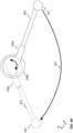
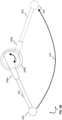
- Figures 4A and 4B illustrate a non-limiting example of the use position of the boom microphone 104 and the non-use position of the boom microphone.
- the orientation of the rotating element 206 is such that, when the headset 100 is in use, i.e. worn by a user, the face of the user is facing substantially to the positive X-direction and the top of the head of the user is facing substantially to the positive Y-direction.
- the headset 100 is arranged to a helmet, the top of the helmet is facing substantially to the positive Y-direction and the opening in the helmet for the face of a user of the helmet is facing substantially to the positive X-direction (see Figures 6A and 6B ).
- the boom microphone is first in the use position, e.g. substantially in the front of the mouth of the user, and the boom microphone 104 may be used.
- the boom microphone 104 In the use position of the boom microphone 104, the boom microphone 104 is active and the skull microphone is deactivated.
- the user may rotate the boom microphone 104 from the use position, e.g. from the front of the mouth of the user, to the non-use position, e.g. behind the neck of the user, in order to activate the skull microphone and deactivate the boom microphone 104.
- the boom microphone 104 illustrated with solid lines represents the boom microphone 104 in the use position and the boom microphone 104 illustrated with dashed lines represents the boom microphone 104 in the non-use position.
- the arrow 402 in Figure 4A illustrates the movement direction of the boom microphone 104 from the use position to the non-use position, wherein the movement of the boom microphone 104 provided by the rotating element 206 is rotating movement around the rotation axis of the rotating element 206.
- the use position may be the first limit position and the non-use position may be the second limit position as discussed above, i.e. the boom microphone may be moved between the first and second limit positions.
- the boom microphone 104 is first in the non-use position, e.g. behind the neck of the user, and the skull microphone 102 may be used.
- the skull microphone 106 is active and the boom microphone 104 is deactivated.
- the user may turn the boom microphone 104 from the non-use position, e.g. from behind the neck of the user, to the use position, e.g. to substantially front of the mouth of the user in order to activate the boom microphone 104 and deactivate the skull microphone 102.
- the boom microphone 104 illustrated with solid lines represents the boom microphone 104 in the non-use position and the boom microphone 104 illustrated with dashed lines represents the boom microphone 104 in the use position.
- the arrow 404 in Figure 4B illustrates the movement direction of the boom microphone 104 from the non-use position to the use position, wherein the movement of the boom microphone 104 provided by the rotating element 206 is rotating movement around the rotation axis of the rotating element 206.
- the switch 502 may be arranged to the speaker unit 102.
- the switch 502 may be used to connect and disconnect grounds or signals of the boom microphone 104 and the skull microphone 106 in order to activate the boom microphone 104 or the skull microphone 106 based on the position of the boom microphone 104.
- the headset 100 may further comprise an actuator 504 that may be arranged to the rotating element 206 of the boom microphone 104 in order to enable the that the switch 502 may be used to activate the boom microphone 104 or the skull microphone 106 based on the position of the boom microphone 104.
- the actuator 504 may be a separate part that may be fixed to the rotating element 206. Alternatively, the actuator 504 may be an integral part of the rotating element 206.
- the actuator 504 may be arranged to the rotating element 206 so that the switch 502 may activate the boom microphone 104, when the boom microphone is in its use position, and activate the skull microphone 106, when the boom microphone 104 is in its non-use position. This may be provided so that the actuator 504 is arranged to the first part 206a of rotating element 206, e.g. to the protruding part (as illustrated in Figures 5A-5D ), that is movable with respect to the speaker unit 102 to which the switch 502 may be arranged.
- the switch 502 may be arranged to the speaker unit 102 so that when the boom microphone 104 is in the non-use position, the actuator 504 arranged to the rotating element 206 is in a close vicinity of the switch 502, i.e. the actuator 504 is within an operational area of the switch 502 to enable that the state of the switch 502 may change.
- the switch may be a reed switch that is a passive mechanical switch, which state (open or closed) may be changed by applying a magnetic field.
- the reed switch may be normally open and when a magnetic field is present the switch is closed or vice versa.
- the magnetic field may be applied by arranging a magnet, i.e. the actuator, in a close vicinity of the switch to change the state of the reed switch, i.e. from open to closed or closed to open.
- the state of the reed switch is changed back by moving the magnet away from the reed switch causing that the magnetic field ceases.
- the use of the reed switch as the switch 502 and the magnet as the actuator 504 enables a simple mechanical switching solution.
- the switch 502 may be for example an electromechanical switch, an optomechanical switch, or a mechanical switch, such as a micro switch or optoswitch.
- the actuator 504 may be a mechanical actuator.
- electromechanical switch and micro switch the state of the switch may be changed by arranging the mechanical actuator, e.g. mechanical part, to press the switch.
- optoelectrical switch and optoswitch the state of the switch may be changed by arranging the mechanical actuator, e.g. mechanical part, so that it switches of the beam of light.
- FIGs 5A-5D Examples of the operation of the switch 502 are illustrated in Figures 5A-5D , wherein two non-limiting example locations of the switch 502 are presented.
- the orientation of the rotating element 206 is such that, when the headset 100 is in use, i.e. worn by a user, the face of the user is facing substantially to the positive X-direction and the top of the head of the user is facing substantially to the positive Y-direction.
- the headset 100 is arranged to a helmet
- the top of the helmet is facing substantially to the positive Y-direction and the opening in the helmet for the face of a user of the helmet is facing substantially to the positive X-direction (see Figures 6A and 6B ).
- Figures 5A and 5B illustrate an example, wherein the switch 502 is arranged substantially behind the rotating element 206 in X-direction causing that the in the non-use position the boom microphone 104 is arranged substantially behind the neck of the user or towards the back portion of a helmet, if the headset 100 is arranged to a helmet.
- the boom microphone 104 is in the use position and the switch 502 and the actuator 504 are far away from each other, which means that the actuator 504 is outside the operational area of the switch 502.
- the reed switch 502 it means that the reed switch is not affected by the magnet so there is no magnetic field present around the reed switch and the reed switch is in its first state, i.e.
- the switch 502 connects the ground or signal of the boom microphone 104 and disconnect the ground or signal of the skull microphone 106, respectively.
- the boom microphone 104 is in the non-use position and the actuator 504 is in a close vicinity of the switch 502, which means that the actuator 504 is within the operational area of the switch 502.
- the switch 502 disconnects the ground or signal of the boom microphone 104 and connect the ground or signal of the skull microphone 106, respectively.
- Figures 5C and 5D illustrates another example, wherein the switch 502 is arranged substantially on top the rotating element 206 (in Y-direction) causing that in the non-used position of the boom microphone 104 is arranged substantially towards the top of the head of the user or towards the top of the helmet, if the headset 100 is arranged to a helmet.
- the boom microphone 104 is in the use position and the switch 502 and the actuator 504 are far away from each other, which means that the actuator 504 is outside the operational area of the switch 502.
- the switch 502 connects the ground or signal of the boom microphone 104 and disconnect the ground or signal of the skull microphone 106, respectively.
- the boom microphone 104 is in the non-use position and the actuator 504 is in a close vicinity of the switch 502, which means that the actuator 504 is within the operational area of the switch 502.
- the switch 502 disconnects the ground or signal of the boom microphone 104 and connect the ground or signal of the skull microphone 106, respectively.
- the location of the switch 502 defines the non-use position of the boom microphone 104.
- the switch 502 and the actuator 504 should be arranged to the headset 100 so that they may provide the switching, i.e. actuation or selection, between the boom microphone 104 and skull microphone 106 at a desired non-use position of the boom microphone 104.
- the non-use position of the boom microphone 104 may be almost any position of the boom microphone 104 that may be provided with the rotating element 206 and the non-use position may be defined by arranging the actuator 504 and the switch 502 to the different components of the headset 100 so that the actuator 504 causes that the switch changes its state at said location, for example in case of reed switch by arranging the magnet and the reed switch to the different components of the headset 100 so that the magnet causes magnetic field to the switch 502 at said location.
- the switch 502 may be arranged to a location that corresponds one of the stepped positions of the rotating element 206.
- the first limit position and the position between the limit positions may be the use positions and the second limit position may be the non-use position, thus the switch 502 may be arranged to the location that corresponds the second limit position.
- the non-use position of the boom microphone 104 is such that the boom 202 and/or the microphone 204 arranged in the far end of the boom 202 does not disturb the user, if the space around the normal use position of the boom microphone 104 is needed to be free or is occupied for some other entity, for example for breathing mask.
- the microphone 204 arranged in the far end of the boom 204 is not shown in Figures 5A-5D .
- the headset 100 may comprise at least two switches to provide at least two optional non-use positions of the boom microphone 104.
- the headset 100 may comprise one switch arranged to a first location, e.g. to the example location illustrated in Figures 5A and 5B , to define a first non-use position of the boom microphone 104 and another switch arranged to a second location, e.g. to the example location illustrated in Figures 5C and 5D to define a second non-use position of the boom microphone 104. This enables that the boom microphone 104 may be moved, i.e.
- the second switch i.e. the second non-use position may be arranged to a location between the use position and the first non-use position.
- the headset 100 described above may be mounted or arranged to a helmet, e.g. a firefighter helmet, military helmet, police helmet, etc.
- a helmet e.g. a firefighter helmet, military helmet, police helmet, etc.
- the headset 100 enables that the firefighter may easily switch between the boom microphone 104 and skull microphone only by moving, i.e. rotating around the rotation axis of the rotating element 206, the boom microphone 104 from the use position to the non-use position or from the non-use position to the use-position.
- the skull microphone 106 may be activated by moving the boom microphone 104 from the use position to the non-use position or the boom microphone 104 may be activated by moving the boom microphone 104 from the non-use position to the use position.
- Figures 6A and 6B illustrate an example, wherein the headset 100 is arranged to a helmet 600.
- the speaker unit 102, the skull microphone 102 and the rotating element 206 of the boom microphone 104 are arranged inside the helmet 600.
- the boom microphone 104 arranged in a use position causing that the boom microphone 104 is activated.
- the use position of the boom microphone 104 in Figure 6A is such that the microphone 204 arranged in the far end of the boom 202 is substantially front of the mouth of the user, i.e. facing the mouth of the user.
- the boom microphone 104 is arranged in a non-use position causing that the skull microphone 106 is activated.
- the non-use position of the boom microphone 104 in Figure 6B is such that the microphone 204 arranged in the far end of the boom 202 is substantially behind the neck of the user.
- the boom 202 is illustrated as a straight tube in Figures 2-6 , but, the boom 202 may be provided as a deformable tube that may be bent by a user to enable adjusting the microphone 204 arranged in the far end of the boom 202 to a desired position with respect to himself/herself and/or with respect to the speaker unit 102 or the helmet 600.
- the boom 202 may comprise at least one deformable tube section that is bendable by a user and at least one rigid tube section or substantially rigid tube section to enable adjusting the microphone 204 arranged to the far end of the boom 202 to a desired position with respect to the user and/or with respect to the speaker unit 102 or the helmet 600.
- the above described adjustment of the position of the boom microphone 104, i.e. bending of the boom 202 of the boom microphone 104, enabled by at least partly the deformable tube of the boom 202 is not considered as a movement of the boom microphone 104 based on which the switch 502 may activate the boom microphone 104 or the skull microphone 106.
- Said adjustment of the position of the boom microphone 104, i.e. bending of the boom 202 of the boom microphone 104 may be provided, when the boom microphone 104 is in its use position.
- the boom 202 may be bent into a suitable, typically curved shape to bring the microphone 204 arranged in the far end of the boom 202 a desired position.
- the adjustment of the position of the boom microphone 104 i.e.
- bending of the boom 202 of the boom microphone 104 may be provided, when the boom microphone 104 is in its non-use position.
- the adjustment of the position of the boom microphone 104 i.e. bending of the boom 202 of the boom microphone 104, may be provided during the rotating movement of the boom microphone 104 provided by the rotating element 206. This allows that the boom microphone 104 may be rotated from the use position, e.g. from the front of the mouth of the user, to the non-use position, e.g. behind the neck of the user.
- the above described headset 100 allows that the user of the headset 100 may simply and easily select/switch between the use of a boom microphone 104 and a skull microphone 106 depending on the use case, which in turn improves the sound quality of the microphone in different use cases.
- the skull microphone 106 may provide the best sound quality, when e.g. breathing mask is used, and the boom microphone 104 may provide the best sound quality in many other use cases.
- the selection/switching between the boom microphone and the skull microphone may be provided without the need to attach and/or detach any microphones.
- the headset 100 according to the invention may be implemented or arranged to any kind of helmets, e.g. a firefighter helmet, military helmet, police helmet, etc.
Landscapes
- Physics & Mathematics (AREA)
- Engineering & Computer Science (AREA)
- Acoustics & Sound (AREA)
- Signal Processing (AREA)
- Helmets And Other Head Coverings (AREA)
- Headphones And Earphones (AREA)
- Details Of Audible-Bandwidth Transducers (AREA)
Description
- The invention concerns in general the technical field of headsets. Especially the invention concerns headsets for helmets.
- Typically, a headset comprises a speaker unit, such as headphones, and a microphone, such as boom microphone, skull microphone, throat microphone, etc. The headset is a common accessory to helmets or protective headgear of type worn by professional personnel working in potentially hazardous conditions such as firefighters, airline pilots, military personnel, policemen, etc. Moreover, people working in noisy environments such as factories or construction sites may have a headset mounted in a protective headgear they may wear while working. Yet further, a headset enables hands-free telecommunication when further connected e.g. to a mobile phone or to a computer, which results in a wide range of usage scenarios including professional and everyday use.
- For certain use cases, especially on the professional side, sound quality of certain type of microphone is worse than other type of microphones. For example, when a firefighter is wearing a breathing mask, e.g. during smoke diving, the skull microphone or throat microphone may provide better sound quality than the boom microphone, although the boom microphone may provide better sound quality in many other use cases.
- According to one prior art solution the microphone of the headset may be changed depending on the use case. At least one drawback of the prior art solution is that the user has to carry several different types of microphones with him/her. Furthermore, the change between different type of microphones is time-consuming, because first the current microphone must be detached from the headset and after that the other microphone must be attached to the headset.
- A patent application
WO 2018/046637 A1 discloses a communication device for use with a personal protection system. The communication device includes a microphone module and a loudspeaker module. A first microphone is arranged in a first housing section of the microphone module and a second microphone is arranged in a second housing section of the microphone module. The first housing section includes an insertion mechanism for inserting the first housing section into the loudspeaker module in a first functional mode or for inserting the first housing section into a receiving element or holding device mounted to a protective head gear device, such as a mask, in a second functional mode. - A patent application
WO 2008/010826 A1 discloses a headset utilizing an extendable microphone boom that positions the microphone closer to the user's mount when deployed. - A patent application
DE 10 2013 011195 A1 discloses a personal protection system comprising a helmet, a first microphone, e.g. a boom microphone, arranged to the helmet, and a second microphone arranged to a breathing protection mask. - A patent application
US 2006/286933 A1 discloses a wireless communications system defining a wireless personal area network enabling reliable communications between members of workers in a group wearing compatible systems. Each member of a group is fitted with a communications system having a microphone, a transceiver and a speaker. - A patent application
US 2012/052924 A1 discloses a compact lightweight communication device comprising a wireless headset or wireless earset. - A patent application
WO 99/45686 A1 - The following presents a simplified summary in order to provide basic understanding of some aspects of various invention embodiments. The summary is not an extensive overview of the invention. It is not intended to identify key or critical elements of the invention.
- The following summary merely presents some concepts of the invention in a simplified form as a prelude to a more detailed description of exemplifying embodiments of the invention.
- An objective of the invention is to present a headset for a helmet and a helmet comprising a headset. Another objective of the invention is that the headset for a helmet and the helmet comprising the headset enable simply and easy switching between a boom microphone and the skull microphone depending on the use case.
- The objectives of the invention are reached by a headset and a helmet as defined by the independent claims.
- According to a first aspect, a headset for a helmet is provided, wherein the headset comprises a speaker unit, a boom microphone and a skull microphone, wherein the headset further comprises a switch configured to activate the boom microphone or the skull microphone based on the position of the boom microphone.
- Moreover, the switch may be configured to: activate the boom microphone and simultaneously deactivate the skull microphone, when the boom microphone is arranged to a use position; and deactivate the boom microphone and simultaneously activate the skull microphone, when the boom microphone is arranged to a non-use position.
- The boom microphone comprises a rotating element enabling that the boom microphone is movable between a plurality of positions of the boom microphone, wherein the rotating element is mechanically mountable to the speaker unit or to the helmet.
- The headset further comprises an actuator arranged to the rotating element, wherein when the boom microphone is in the use position, the actuator is far from the switch arranged to the speaker unit and the switch is in its first state, thereby causing that the switch is configured to connect the ground or signal of the boom microphone and disconnect the ground or signal of the skull microphone, respectively, to activate the boom microphone and deactivate the skull microphone; and when the boom microphone is in the non-use position, the actuator is in a close vicinity to the switch and the switch is in its second state, thereby causing that the switch is configured to disconnect the ground or signal of the boom microphone and connect the ground or signal of the skull microphone, respectively, to deactivate the boom microphone and activate the skull microphone.
- The switch may be a reed switch and the actuator may be a magnet.
- Alternatively or in addition, the switch may be an electromechanical switch, an optomechanical switch, or a mechanical switch, such as a micro switch or optoswitch, and the actuator may be a mechanical actuator.
- The boom microphone may comprise a boom having a microphone arranged in its far end.
- Furthermore, the boom microphone may be detachably mounted to the speaker unit or the helmet with mechanical coupling means.
- The skull microphone may be fixedly coupled to the speaker unit.
- According to a second aspect, a helmet is provided, wherein the helmet comprises the headset described above.
- Various exemplifying and non-limiting embodiments of the invention both as to constructions and to methods of operation, together with additional objects and advantages thereof, will be best understood from the following description of specific exemplifying and non-limiting embodiments when read in connection with the accompanying drawings.
- The verbs "to comprise" and "to include" are used in this document as open limitations that neither exclude nor require the existence of unrecited features. The features recited in dependent claims are mutually freely combinable unless otherwise explicitly stated. Furthermore, it is to be understood that the use of "a" or "an", i.e. a singular form, throughout this document does not exclude a plurality.
- The embodiments of the invention are illustrated by way of example, and not by way of limitation, in the figures of the accompanying drawings.
-
Figure 1 schematically illustrates a headset according to a simple example. -
Figure 2 schematically illustrates an exploded-view drawing of a boom microphone according to an example. -
Figures 3A and 3B schematically illustrate examples of a rotating element of a boom microphone. -
Figures 4A and4B schematically illustrate an example of use position of a boom microphone and non-use position of a boom microphone. -
Figures 5A-5D schematically illustrate operation of a switch of a headset. -
Figures 6A and 6B illustrate an example of a headset arranged to a helmet. -
Figure 1 schematically illustrates some components of aheadset 100 according to a simple example. Theheadset 100 comprises aspeaker unit 102, aboom microphone 104, and askull microphone 106. As a few non-limiting examples, thespeaker unit 102 may be headphones, earphones, earpiece, hearing protectors, etc. Theskull microphone 106 may be fixedly coupled to thespeaker unit 102 with a cable comprising a plurality of electrical wires arranged inside the cable in order to electrically couple theskull microphone 106 to thespeaker unit 102. The skull microphone may be mechanically mountable to a helmet for example with a hook-and-loop fastened, such as Velcro, or with any other similar kind of mounting means. -
Figure 2 schematically illustrates an exploded-view drawing of aboom microphone 104 according to an example. Theboom microphone 104 comprises aboom 202 having amicrophone 204 arranged in its far end. As a few non-limiting examples, themicrophone 204 arranged in the far end of theboom 202 may be a dynamic microphone or an electret microphone using a single-ended or differential configuration. Theboom microphone 104 further comprises a rotatingelement 206 to which the other end of theboom 202 may be mounted. The end of theboom 202 that has themicrophone 204 arranged therein may be referred to as a far end whereas the other end of theboom 202 that is mountable to the rotatingelement 206 may be referred to as a near end. Theboom 206 may comprise a mountingarrangement 208 in the near end of theboom 202 in order to mechanically and electrically couple themicrophone 204 arranged in the far end of theboom 202 to therotating element 206. Theboom 202 having themicrophone 204 may be detachably mounted to therotating element 206. Alternatively, theboom 202 having themicrophone 204 may be fixedly mounted to therotating element 206. -
Figures 3A and 3B schematically illustrate examples of therotating element 206 of theboom microphone 104. For sake of clarity themicrophone 204 arranged in the far end of theboom 204 is not shown inFigures 3A and 3B . InFigures 3A and 3B the orientation of therotating element 206 is such that, when theheadset 100 is in use, i.e. worn by a user, the face of the user is facing substantially to the positive X-direction and the top of the head is facing substantially to the positive Y-direction. In case theheadset 100 is arranged to a helmet the top of the helmet is facing substantially to the positive Y-direction and the opening in the helmet for the face of a user of the helmet is facing substantially to the positive X-direction (seeFigures 6A and 6B ). Therotating element 206 may be mechanically coupled, i.e. mounted, to thespeaker unit 102 or to a helmet, to which theheadset 100 may be mounted, with mechanical coupling means 310. InFigures 3A and 3B a non-limiting example of the mechanical coupling means 310 is illustrated with which therotating element 206 may be hanged to thespeaker unit 102, e.g. to an ear cup of headphones or an ear cup of a hearing protector. According to another non-limiting example the rotating element may be coupled to any type of helmet with a strap type mechanical coupling means 310. Alternatively, any other mechanical coupling means 310 may be used to mechanically couple therotating element 206 to thespeaker unit 102 or to the helmet. - The
rotating element 206 enables that theboom microphone 104 is movable between a plurality of positions of theboom microphone 104. The movement of theboom microphone 104 provided by therotating element 206 is rotating movement around the rotation axis of therotating element 206. The rotation axis is perpendicular to the XY-plane. The rotating movement of theboom microphone 104 provided by therotating element 206 may be continuous or stepped. Therotating element 206 enables that theboom microphone 104 is movable in both directions, i.e. in clockwise direction and in counter clockwise direction. Therotating element 206 may enable that theboom microphone 104 may be rotatable continuously or stepwise around the rotation axis of therotating element 206. Alternatively, therotating element 206 may enable that the boom microphone may be rotatable continuously or stepwise between two limit positions so that theboom microphone 104 is not allowed to rotate full 360 degrees. Therotating element 206 may comprise twoparts boom microphone 104 mounted to thefirst part 206a of therotating part 206 between a plurality of positions of theboom microphone 104.Figures 3A and 3B illustrate two different positions of theboom microphone 104 provided by rotating therotating element 206. Thesecond part 206b of therotating element 206 may be mechanically coupled to thespeaker unit 102 with the mechanical coupling means 310 causing that thesecond part 206b is stationary and thefirst part 206a is rotatable with respect to thesecond part 206b. Thefirst part 206a may comprise a protruding part to which theboom 202 of theboom microphone 104 may be mounted. - In case the
boom 202 is detachably mountable to therotating element 206, the mountingarrangement 208 in the near end of theboom 202 may comprise anaudio plug 210 and therotating element 206 may be provided with a matching audio socket (not shown in the figures) for electrical coupling themicrophone 204 arranged in the far end of theboom 202 to therotating element 206. Theaudio plug 210 is secured to the near end of theboom 202 and is further electrically coupled to themicrophone 204 in the far end of theboom 202, thereby electrically coupling themicrophone 204 to therotating element 206. The electrical coupling may be provided by a plurality of electrical wires arranged inside theboom 202, which electrical wires are electrically connected to theaudio plug 210 in one end and to themicrophone 204 in the other end. The applied or required number of electrical wires typically depends on the requirements of the employed microphone type and is hence selected accordingly. The audio socket may be provided to the protruding part of thefirst part 206a of therotating element 206. The audio socket of therotating element 206 is electrically coupled to further components of an audio processing arrangement within and/or outside theheadset 100, such as thespeaker unit 102, for example with a cable comprising a plurality of electrical wires arranged inside the cable. Theaudio plug 210 may be provided as a suitable audio connector known in the art, e.g. as a four-conductor or five-conductor 3.5 mm audio plug, while the audio socket in therotating element 206 is provided as a matching audio socket (audio jack). - In case the
boom 202 is fixedly mounted to therotating element 206, themicrophone 204 in the far end of theboom 202, is electrically coupled to therotating element 206 by a plurality of electrical wires arranged inside theboom 202. Therotating element 206 is electrically coupled to further components of an audio processing arrangement within and/or outside theheadset 100, such as thespeaker unit 102, for example with a cable comprising a plurality of electrical wires arranged inside the cable. - The
headset 100 further comprises aswitch 502 to activate theboom microphone 104 or theskull microphone 106 based on the position of theboom microphone 104. Theswitch 502 may activate theboom microphone 104 and simultaneously deactivate theskull microphone 106, when theboom microphone 104 is arranged in at least one use position. Theswitch 502 may deactivate theboom microphone 104 and simultaneously activate theskull microphone 106, when theboom microphone 104 is arranged in at least one non-use position. The use position of theboom microphone 104 may be for example such that themicrophone 204 arranged in the far end of theboom 202 is substantially front of the mouth of the user, i.e. facing the mouth of the user. In case that theheadset 100 is mounted to a helmet the use position of theboom microphone 104 is typically such that themicrophone 204 arranged in the far end of theboom 202 is substantially at the front of the helmet. The non-use position of theboom microphone 104 may be for example a tilt position, wherein theboom 202 and/or themicrophone 204 arranged in the far end of theboom 202 does not disturb the user, if the space around the use position of theboom microphone 104 is needed to be free or is occupied for some other entity, for example for breathing mask. One non-limiting example of the non-used position is a position, wherein theboom microphone 104, i.e. theboom 202 and/or themicrophone 204 arranged in the far end of theboom 202, is arranged substantially behind the neck of the user or towards the back portion of a helmet, if theheadset 100 is arranged to a helmet. Alternatively or in addition, the non-used position of theboom microphone 104 may be a position, wherein theboom microphone 104, i.e. theboom 202 and/or themicrophone 204 arranged in the far end of theboom 202, is arranged substantially towards the top of the head of the user or towards the top of the helmet, if theheadset 100 is arranged to a helmet, i.e. substantially to the direction of the positive Y-direction in Figures. - Preferably, in case the
rotating element 206 enables that the boom microphone may be rotatable continuously or stepwise between two limit positions, the use position may be arranged at the first limit position and the non-use position may be arranged at the second limit position. Alternatively or in addition, the use position and/or the non-use position may be arranged to be any other position between the two limit positions. For example, in case the rotating movement of theboom microphone 104 provided by therotating element 206 is stepwise movement and theboom microphone 104 may be configured to be movable between at least two positions, i.e. at least between the limit positions, the use position may be arranged at least at the first limit position and the non-use position may be arranged at the second limit position. For example, if therotating element 206 has three stepped positions between which theboom microphone 104 may be movable, the first limit position and the position between the limit positions may be the use positions and the second limit position may be the non-use position. According to another example, if therotating element 206 has three stepped positions between which theboom microphone 104 may be movable, the first limit position may be the use position and the second limit position and the position between the limit positions may be the non-use positions. The invention is not limited to the example number of stepped positions of therotating element 206 described above and any number of stepped positions may be used. -
Figures 4A and4B illustrate a non-limiting example of the use position of theboom microphone 104 and the non-use position of the boom microphone. InFigures 4A and4B the orientation of therotating element 206 is such that, when theheadset 100 is in use, i.e. worn by a user, the face of the user is facing substantially to the positive X-direction and the top of the head of the user is facing substantially to the positive Y-direction. In case theheadset 100 is arranged to a helmet, the top of the helmet is facing substantially to the positive Y-direction and the opening in the helmet for the face of a user of the helmet is facing substantially to the positive X-direction (seeFigures 6A and 6B ). InFigure 4A the boom microphone is first in the use position, e.g. substantially in the front of the mouth of the user, and theboom microphone 104 may be used. In the use position of theboom microphone 104, theboom microphone 104 is active and the skull microphone is deactivated. In a use case, where the skull microphone would be more suitable than the boom microphone, the user may rotate theboom microphone 104 from the use position, e.g. from the front of the mouth of the user, to the non-use position, e.g. behind the neck of the user, in order to activate the skull microphone and deactivate theboom microphone 104. InFigure 4A theboom microphone 104 illustrated with solid lines represents theboom microphone 104 in the use position and theboom microphone 104 illustrated with dashed lines represents theboom microphone 104 in the non-use position. Thearrow 402 inFigure 4A illustrates the movement direction of theboom microphone 104 from the use position to the non-use position, wherein the movement of theboom microphone 104 provided by therotating element 206 is rotating movement around the rotation axis of therotating element 206. According to an example, the use position may be the first limit position and the non-use position may be the second limit position as discussed above, i.e. the boom microphone may be moved between the first and second limit positions. - In the example illustrated in
Figure 4B theboom microphone 104 is first in the non-use position, e.g. behind the neck of the user, and theskull microphone 102 may be used. In the non-use position of theboom microphone 104, theskull microphone 106 is active and theboom microphone 104 is deactivated. In a use case, where theboom microphone 104 would be more suitable than theskull microphone 106, the user may turn theboom microphone 104 from the non-use position, e.g. from behind the neck of the user, to the use position, e.g. to substantially front of the mouth of the user in order to activate theboom microphone 104 and deactivate theskull microphone 102. InFigure 4B theboom microphone 104 illustrated with solid lines represents theboom microphone 104 in the non-use position and theboom microphone 104 illustrated with dashed lines represents theboom microphone 104 in the use position. Thearrow 404 inFigure 4B illustrates the movement direction of theboom microphone 104 from the non-use position to the use position, wherein the movement of theboom microphone 104 provided by therotating element 206 is rotating movement around the rotation axis of therotating element 206. - The
switch 502 may be arranged to thespeaker unit 102. Theswitch 502 may be used to connect and disconnect grounds or signals of theboom microphone 104 and theskull microphone 106 in order to activate theboom microphone 104 or theskull microphone 106 based on the position of theboom microphone 104. Theheadset 100 may further comprise anactuator 504 that may be arranged to therotating element 206 of theboom microphone 104 in order to enable the that theswitch 502 may be used to activate theboom microphone 104 or theskull microphone 106 based on the position of theboom microphone 104. Theactuator 504 may be a separate part that may be fixed to therotating element 206. Alternatively, theactuator 504 may be an integral part of therotating element 206. - The
actuator 504 may be arranged to therotating element 206 so that theswitch 502 may activate theboom microphone 104, when the boom microphone is in its use position, and activate theskull microphone 106, when theboom microphone 104 is in its non-use position. This may be provided so that theactuator 504 is arranged to thefirst part 206a ofrotating element 206, e.g. to the protruding part (as illustrated inFigures 5A-5D ), that is movable with respect to thespeaker unit 102 to which theswitch 502 may be arranged. Theswitch 502, in turn, may be arranged to thespeaker unit 102 so that when theboom microphone 104 is in the non-use position, theactuator 504 arranged to therotating element 206 is in a close vicinity of theswitch 502, i.e. theactuator 504 is within an operational area of theswitch 502 to enable that the state of theswitch 502 may change. - According to an example, the switch may be a reed switch that is a passive mechanical switch, which state (open or closed) may be changed by applying a magnetic field. For example, the reed switch may be normally open and when a magnetic field is present the switch is closed or vice versa. The magnetic field may be applied by arranging a magnet, i.e. the actuator, in a close vicinity of the switch to change the state of the reed switch, i.e. from open to closed or closed to open. The state of the reed switch is changed back by moving the magnet away from the reed switch causing that the magnetic field ceases. The use of the reed switch as the
switch 502 and the magnet as theactuator 504 enables a simple mechanical switching solution. - Alternatively, the
switch 502 may be for example an electromechanical switch, an optomechanical switch, or a mechanical switch, such as a micro switch or optoswitch. If theswitch 502 is an electromechanical switch, an optomechanical switch or mechanical switch, theactuator 504 may be a mechanical actuator. In case of electromechanical switch and micro switch the state of the switch may be changed by arranging the mechanical actuator, e.g. mechanical part, to press the switch. In case of optoelectrical switch and optoswitch the state of the switch may be changed by arranging the mechanical actuator, e.g. mechanical part, so that it switches of the beam of light. - Examples of the operation of the
switch 502 are illustrated inFigures 5A-5D , wherein two non-limiting example locations of theswitch 502 are presented. InFigures 5A-5D the orientation of therotating element 206 is such that, when theheadset 100 is in use, i.e. worn by a user, the face of the user is facing substantially to the positive X-direction and the top of the head of the user is facing substantially to the positive Y-direction. In case theheadset 100 is arranged to a helmet, the top of the helmet is facing substantially to the positive Y-direction and the opening in the helmet for the face of a user of the helmet is facing substantially to the positive X-direction (seeFigures 6A and 6B ). -
Figures 5A and 5B illustrate an example, wherein theswitch 502 is arranged substantially behind therotating element 206 in X-direction causing that the in the non-use position theboom microphone 104 is arranged substantially behind the neck of the user or towards the back portion of a helmet, if theheadset 100 is arranged to a helmet. InFigure 5A theboom microphone 104 is in the use position and theswitch 502 and theactuator 504 are far away from each other, which means that theactuator 504 is outside the operational area of theswitch 502. For example, in case of thereed switch 502 it means that the reed switch is not affected by the magnet so there is no magnetic field present around the reed switch and the reed switch is in its first state, i.e. normal state. In this case, theswitch 502 connects the ground or signal of theboom microphone 104 and disconnect the ground or signal of theskull microphone 106, respectively. InFigure 5B theboom microphone 104 is in the non-use position and theactuator 504 is in a close vicinity of theswitch 502, which means that theactuator 504 is within the operational area of theswitch 502. For example, in case of the reed switch it means that the reed switch is affected by the magnet so there is magnetic field present around the reed switch and the reed switch is in its second state. In this case, theswitch 502 disconnects the ground or signal of theboom microphone 104 and connect the ground or signal of theskull microphone 106, respectively. When the ground of a microphone is connected, said microphone is active and when the ground of a microphone is disconnected, said microphone is deactivated. -
Figures 5C and 5D illustrates another example, wherein theswitch 502 is arranged substantially on top the rotating element 206 (in Y-direction) causing that in the non-used position of theboom microphone 104 is arranged substantially towards the top of the head of the user or towards the top of the helmet, if theheadset 100 is arranged to a helmet. InFigure 5C theboom microphone 104 is in the use position and theswitch 502 and theactuator 504 are far away from each other, which means that theactuator 504 is outside the operational area of theswitch 502. In this case, theswitch 502 connects the ground or signal of theboom microphone 104 and disconnect the ground or signal of theskull microphone 106, respectively. InFigure 5D theboom microphone 104 is in the non-use position and theactuator 504 is in a close vicinity of theswitch 502, which means that theactuator 504 is within the operational area of theswitch 502. In this case, theswitch 502 disconnects the ground or signal of theboom microphone 104 and connect the ground or signal of theskull microphone 106, respectively. - From the examples illustrated in
Figures 5A-5D it may be seen that the location of theswitch 502 defines the non-use position of theboom microphone 104. Theswitch 502 and theactuator 504 should be arranged to theheadset 100 so that they may provide the switching, i.e. actuation or selection, between theboom microphone 104 andskull microphone 106 at a desired non-use position of theboom microphone 104. In other words, the non-use position of theboom microphone 104 may be almost any position of theboom microphone 104 that may be provided with therotating element 206 and the non-use position may be defined by arranging theactuator 504 and theswitch 502 to the different components of theheadset 100 so that theactuator 504 causes that the switch changes its state at said location, for example in case of reed switch by arranging the magnet and the reed switch to the different components of theheadset 100 so that the magnet causes magnetic field to theswitch 502 at said location. In case therotating element 206 rotates theboom microphone 104 stepwise, theswitch 502 may be arranged to a location that corresponds one of the stepped positions of therotating element 206. For example, if therotating element 206 has three stepped positions between which theboom microphone 104 may be movable, the first limit position and the position between the limit positions may be the use positions and the second limit position may be the non-use position, thus theswitch 502 may be arranged to the location that corresponds the second limit position. Preferably, the non-use position of theboom microphone 104 is such that theboom 202 and/or themicrophone 204 arranged in the far end of theboom 202 does not disturb the user, if the space around the normal use position of theboom microphone 104 is needed to be free or is occupied for some other entity, for example for breathing mask. For sake of clarity themicrophone 204 arranged in the far end of theboom 204 is not shown inFigures 5A-5D . - According to one example, the
headset 100 may comprise at least two switches to provide at least two optional non-use positions of theboom microphone 104. For example, theheadset 100 may comprise one switch arranged to a first location, e.g. to the example location illustrated inFigures 5A and 5B , to define a first non-use position of theboom microphone 104 and another switch arranged to a second location, e.g. to the example location illustrated inFigures 5C and 5D to define a second non-use position of theboom microphone 104. This enables that theboom microphone 104 may be moved, i.e. rotated, either to the first non-use position or to the second non-use position to activate theskull microphone 106 and deactivate theboom microphone 104 similarly as discussed above with one non-use position. Alternatively or in addition, the second switch, i.e. the second non-use position may be arranged to a location between the use position and the first non-use position. - The
headset 100 described above may be mounted or arranged to a helmet, e.g. a firefighter helmet, military helmet, police helmet, etc. For example, when theheadset 100 is arranged to a firefighter helmet, theheadset 100 enables that the firefighter may easily switch between theboom microphone 104 and skull microphone only by moving, i.e. rotating around the rotation axis of therotating element 206, theboom microphone 104 from the use position to the non-use position or from the non-use position to the use-position. This allows that when the firefighter is wearing e.g. a breathing mask, theskull microphone 106 may be activated by moving theboom microphone 104 from the use position to the non-use position or theboom microphone 104 may be activated by moving theboom microphone 104 from the non-use position to the use position. -
Figures 6A and 6B illustrate an example, wherein theheadset 100 is arranged to ahelmet 600. Thespeaker unit 102, theskull microphone 102 and therotating element 206 of theboom microphone 104 are arranged inside thehelmet 600. InFigure 6A theboom microphone 104 arranged in a use position causing that theboom microphone 104 is activated. The use position of theboom microphone 104 inFigure 6A is such that themicrophone 204 arranged in the far end of theboom 202 is substantially front of the mouth of the user, i.e. facing the mouth of the user. InFigure 6B theboom microphone 104 is arranged in a non-use position causing that theskull microphone 106 is activated. The non-use position of theboom microphone 104 inFigure 6B is such that themicrophone 204 arranged in the far end of theboom 202 is substantially behind the neck of the user. - For sake of simplicity the
boom 202 is illustrated as a straight tube inFigures 2-6 , but, theboom 202 may be provided as a deformable tube that may be bent by a user to enable adjusting themicrophone 204 arranged in the far end of theboom 202 to a desired position with respect to himself/herself and/or with respect to thespeaker unit 102 or thehelmet 600. Alternatively, theboom 202 may comprise at least one deformable tube section that is bendable by a user and at least one rigid tube section or substantially rigid tube section to enable adjusting themicrophone 204 arranged to the far end of theboom 202 to a desired position with respect to the user and/or with respect to thespeaker unit 102 or thehelmet 600. The above described adjustment of the position of theboom microphone 104, i.e. bending of theboom 202 of theboom microphone 104, enabled by at least partly the deformable tube of theboom 202 is not considered as a movement of theboom microphone 104 based on which theswitch 502 may activate theboom microphone 104 or theskull microphone 106. Said adjustment of the position of theboom microphone 104, i.e. bending of theboom 202 of theboom microphone 104, may be provided, when theboom microphone 104 is in its use position. Theboom 202 may be bent into a suitable, typically curved shape to bring themicrophone 204 arranged in the far end of the boom 202 a desired position. Alternatively or in addition, the adjustment of the position of theboom microphone 104, i.e. bending of theboom 202 of theboom microphone 104, may be provided, when theboom microphone 104 is in its non-use position. Alternatively or in addition, the adjustment of the position of theboom microphone 104, i.e. bending of theboom 202 of theboom microphone 104, may be provided during the rotating movement of theboom microphone 104 provided by therotating element 206. This allows that theboom microphone 104 may be rotated from the use position, e.g. from the front of the mouth of the user, to the non-use position, e.g. behind the neck of the user. - The above described
headset 100 allows that the user of theheadset 100 may simply and easily select/switch between the use of aboom microphone 104 and askull microphone 106 depending on the use case, which in turn improves the sound quality of the microphone in different use cases. For example, theskull microphone 106 may provide the best sound quality, when e.g. breathing mask is used, and theboom microphone 104 may provide the best sound quality in many other use cases. Furthermore, the selection/switching between the boom microphone and the skull microphone may be provided without the need to attach and/or detach any microphones. Theheadset 100 according to the invention may be implemented or arranged to any kind of helmets, e.g. a firefighter helmet, military helmet, police helmet, etc. - The specific examples provided in the description given above should not be construed as limiting the applicability and/or the interpretation of the appended claims. Lists and groups of examples provided in the description given above are not exhaustive unless otherwise explicitly stated.
Claims (8)
- A headset (100) for a helmet (600), the headset (100) comprising a speaker unit (102), a boom microphone (104) and a skull microphone (106), characterized in that the headset (100) further comprises a switch (502) configured to activate the boom microphone (104) or the skull microphone (106) based on the position of the boom microphone (104), wherein the boom microphone (104) comprises a rotating element (206) enabling that the boom microphone (104) is movable between a plurality of positions of the boom microphone (104), wherein the rotating element (206) is mechanically mountable to the speaker unit (102) or to the helmet (600), andwherein the headset (100) further comprises an actuator (504) arranged to the rotating element (206), whereinwhen the boom microphone (104) is in the use position, the actuator (504) is far from the switch (502) arranged to the speaker unit (102) and the switch (502) is in its first state, thereby causing that the switch (502) is configured to connect the ground or signal of the boom microphone (104) and disconnect the ground or signal of the skull microphone (106), respectively, to activate the boom microphone (104) and deactivate the skull microphone (106), andwhen the boom microphone (104) is in the non-use position, the actuator (504) is in a close vicinity to the switch (502) and the switch (502) is in its second state, thereby causing that the switch (502) is configured to disconnect the ground or signal of the boom microphone (104) and connect the ground or signal of the skull microphone (106), respectively, to deactivate the boom microphone (104) and activate the skull microphone (106).
- The headset (100) according to claim 1, wherein the switch (502) is configured to:- activate the boom microphone (104) and simultaneously deactivate the skull microphone (106), when the boom microphone (104) is arranged to a use position, and- deactivate the boom microphone (104) and simultaneously activate the skull microphone (106), when the boom microphone (104) is arranged to a non-use position.
- The headset (100) according to claim 1 or 2, wherein the switch (502) is a reed switch and the actuator (504) is a magnet.
- The headset (100) according to claim 1 or 2, wherein the switch (502) is an electromechanical switch, an optomechanical switch, or a mechanical switch, such as a micro switch or optoswitch, and the actuator (504) is a mechanical actuator.
- The headset (100) according to any of the preceding claims, wherein the boom microphone (104) comprises a boom (202) having a microphone (204) arranged in its far end.
- The headset (100) according to any of the preceding claims, wherein the boom microphone (104) is detachably mounted to the speaker unit (102) or the helmet (600) with mechanical coupling means (310).
- The headset (100) according to any of the preceding claims, wherein the skull microphone (106) is fixedly coupled to the speaker unit (102).
- A helmet (600) comprising the headset (100) according to any of the preceding claims.
Priority Applications (9)
| Application Number | Priority Date | Filing Date | Title |
|---|---|---|---|
| FIEP18178941.3T FI3588973T3 (en) | 2018-06-21 | 2018-06-21 | A headset for a helmet |
| EP18178941.3A EP3588973B1 (en) | 2018-06-21 | 2018-06-21 | A headset for a helmet |
| ES18178941T ES2953439T3 (en) | 2018-06-21 | 2018-06-21 | Headphone for a helmet |
| CA3104583A CA3104583A1 (en) | 2018-06-21 | 2019-06-19 | A headset for a helmet |
| CN201980041222.9A CN112369043B (en) | 2018-06-21 | 2019-06-19 | Headsets for helmets |
| JP2020569977A JP7357648B2 (en) | 2018-06-21 | 2019-06-19 | helmet headset |
| AU2019291044A AU2019291044B2 (en) | 2018-06-21 | 2019-06-19 | A headset for a helmet |
| PCT/EP2019/066210 WO2019243424A1 (en) | 2018-06-21 | 2019-06-19 | A headset for a helmet |
| US17/253,144 US11930878B2 (en) | 2018-06-21 | 2019-06-19 | Headset for a helmet |
Applications Claiming Priority (1)
| Application Number | Priority Date | Filing Date | Title |
|---|---|---|---|
| EP18178941.3A EP3588973B1 (en) | 2018-06-21 | 2018-06-21 | A headset for a helmet |
Publications (2)
| Publication Number | Publication Date |
|---|---|
| EP3588973A1 EP3588973A1 (en) | 2020-01-01 |
| EP3588973B1 true EP3588973B1 (en) | 2023-06-21 |
Family
ID=62750778
Family Applications (1)
| Application Number | Title | Priority Date | Filing Date |
|---|---|---|---|
| EP18178941.3A Active EP3588973B1 (en) | 2018-06-21 | 2018-06-21 | A headset for a helmet |
Country Status (9)
| Country | Link |
|---|---|
| US (1) | US11930878B2 (en) |
| EP (1) | EP3588973B1 (en) |
| JP (1) | JP7357648B2 (en) |
| CN (1) | CN112369043B (en) |
| AU (1) | AU2019291044B2 (en) |
| CA (1) | CA3104583A1 (en) |
| ES (1) | ES2953439T3 (en) |
| FI (1) | FI3588973T3 (en) |
| WO (1) | WO2019243424A1 (en) |
Families Citing this family (9)
| Publication number | Priority date | Publication date | Assignee | Title |
|---|---|---|---|---|
| ES2880033T3 (en) | 2017-11-07 | 2021-11-23 | Locatelli S P A | Crash helmet |
| AU2020274433A1 (en) * | 2019-05-16 | 2021-12-02 | Locatelli S.P.A. | Protective helmet |
| CN115243651B (en) * | 2020-03-09 | 2026-02-03 | 3M创新有限公司 | Adaptive signal routing in a personal protection equipment network |
| EP4080903B1 (en) * | 2020-04-30 | 2025-08-06 | Shenzhen Shokz Co., Ltd. | Acoustic input/output device |
| CN111866637B (en) * | 2020-07-29 | 2025-03-21 | 深圳市豪恩声学股份有限公司 | Microphone rod structure, microphone rod manufacturing method and headphone |
| CN112911448A (en) * | 2021-02-25 | 2021-06-04 | 深圳市佳骏兴科技有限公司 | Earphone set |
| US11700474B2 (en) * | 2021-06-24 | 2023-07-11 | New Audio LLC | Multi-microphone headset |
| US12477263B2 (en) | 2021-06-30 | 2025-11-18 | Epos Group A/S | Headset with detachable arm |
| KR102614678B1 (en) * | 2022-05-03 | 2023-12-19 | 주식회사 라인텍 | Headset apparatus having mute function |
Citations (1)
| Publication number | Priority date | Publication date | Assignee | Title |
|---|---|---|---|---|
| WO2018079575A1 (en) * | 2016-10-28 | 2018-05-03 | パナソニックIpマネジメント株式会社 | Bone conduction microphone, bone conduction head set, and intercommunication device |
Family Cites Families (11)
| Publication number | Priority date | Publication date | Assignee | Title |
|---|---|---|---|---|
| JP3168024B2 (en) * | 1991-06-03 | 2001-05-21 | パイオニア株式会社 | Transmitter |
| US6016347A (en) * | 1998-03-04 | 2000-01-18 | Hello Direct, Inc. | Optical switch for headset |
| JP2002350771A (en) | 2001-05-25 | 2002-12-04 | Nikon Corp | Head mounted display device |
| US7342502B2 (en) * | 2005-06-16 | 2008-03-11 | Consort, Llc | Wireless short range communication system |
| US20080044002A1 (en) * | 2006-07-19 | 2008-02-21 | Bevirt Joeben | Wireless headset with extendable microphone |
| US8818461B2 (en) * | 2010-08-31 | 2014-08-26 | Motorola Mobility Llc | Headset with a pivoting microphone arm and speaker |
| EP2472903B1 (en) * | 2010-12-28 | 2018-09-26 | GN Audio A/S | A headset with rotatable earphone housing |
| US20130089229A1 (en) * | 2011-10-11 | 2013-04-11 | Stefan Kristo | Bone conduction device support |
| CN202496477U (en) * | 2012-01-29 | 2012-10-24 | 佛山市南海永恒头盔制造有限公司 | Communication helmet with bluetooth device |
| DE102013011195B4 (en) * | 2013-07-04 | 2018-02-08 | Dräger Safety AG & Co. KGaA | Personal protection system, helmet, respirator and communication control method |
| DE102016217082A1 (en) * | 2016-09-08 | 2018-03-08 | Msa Europe Gmbh | Communication device for use with a personal protection system |
-
2018
- 2018-06-21 EP EP18178941.3A patent/EP3588973B1/en active Active
- 2018-06-21 ES ES18178941T patent/ES2953439T3/en active Active
- 2018-06-21 FI FIEP18178941.3T patent/FI3588973T3/en active
-
2019
- 2019-06-19 WO PCT/EP2019/066210 patent/WO2019243424A1/en not_active Ceased
- 2019-06-19 CA CA3104583A patent/CA3104583A1/en active Pending
- 2019-06-19 CN CN201980041222.9A patent/CN112369043B/en active Active
- 2019-06-19 US US17/253,144 patent/US11930878B2/en active Active
- 2019-06-19 JP JP2020569977A patent/JP7357648B2/en active Active
- 2019-06-19 AU AU2019291044A patent/AU2019291044B2/en active Active
Patent Citations (1)
| Publication number | Priority date | Publication date | Assignee | Title |
|---|---|---|---|---|
| WO2018079575A1 (en) * | 2016-10-28 | 2018-05-03 | パナソニックIpマネジメント株式会社 | Bone conduction microphone, bone conduction head set, and intercommunication device |
Also Published As
| Publication number | Publication date |
|---|---|
| JP7357648B2 (en) | 2023-10-06 |
| EP3588973A1 (en) | 2020-01-01 |
| AU2019291044A1 (en) | 2021-01-21 |
| AU2019291044B2 (en) | 2024-03-14 |
| JP2021529449A (en) | 2021-10-28 |
| US20210267300A1 (en) | 2021-09-02 |
| ES2953439T3 (en) | 2023-11-13 |
| WO2019243424A1 (en) | 2019-12-26 |
| US11930878B2 (en) | 2024-03-19 |
| CA3104583A1 (en) | 2019-12-26 |
| CN112369043A (en) | 2021-02-12 |
| FI3588973T3 (en) | 2023-09-13 |
| CN112369043B (en) | 2023-05-12 |
Similar Documents
| Publication | Publication Date | Title |
|---|---|---|
| AU2019291044B2 (en) | A headset for a helmet | |
| US6729726B2 (en) | Eyewear for hands-free communication | |
| US7313246B2 (en) | Information system using eyewear for communication | |
| US20040165720A1 (en) | Two-way voice communication device having external acoustic noise reduction | |
| US10455316B2 (en) | Earphone with earphone housing and speaker housing | |
| EP3035697B1 (en) | Headset ear hook with wire holder | |
| CN111294708B (en) | Headphones with ANC feedback microphones arranged behind the speaker diaphragm | |
| US20220086559A1 (en) | Wearable audio device with tri-port acoustic cavity | |
| US20250317683A1 (en) | Communications headset with focused directional speakers | |
| US20190253780A1 (en) | Communication Device for Use with a Personal Protection System | |
| US12439573B2 (en) | Wearable device control module with electrostatic discharge (ESD) protection | |
| AU2019248563B2 (en) | Hearing protector with spectacles | |
| JP7351913B2 (en) | Support member at the front of the temple of the eyeglass structure in protective equipment | |
| CN214154805U (en) | Communication earphone of ear muff formula | |
| WO2019058407A1 (en) | Integratead microphone-easphone headset with a video-communication device for the front real time filming and video-transmission of observed event | |
| GB2520267A (en) | Earpiece | |
| HK40061954A (en) | Support frame for the front part of eyeglasses temples | |
| HK40061954B (en) | Support frame for the front part of eyeglasses temples |
Legal Events
| Date | Code | Title | Description |
|---|---|---|---|
| PUAI | Public reference made under article 153(3) epc to a published international application that has entered the european phase |
Free format text: ORIGINAL CODE: 0009012 |
|
| STAA | Information on the status of an ep patent application or granted ep patent |
Free format text: STATUS: THE APPLICATION HAS BEEN PUBLISHED |
|
| AK | Designated contracting states |
Kind code of ref document: A1 Designated state(s): AL AT BE BG CH CY CZ DE DK EE ES FI FR GB GR HR HU IE IS IT LI LT LU LV MC MK MT NL NO PL PT RO RS SE SI SK SM TR |
|
| AX | Request for extension of the european patent |
Extension state: BA ME |
|
| STAA | Information on the status of an ep patent application or granted ep patent |
Free format text: STATUS: REQUEST FOR EXAMINATION WAS MADE |
|
| 17P | Request for examination filed |
Effective date: 20200629 |
|
| RAP1 | Party data changed (applicant data changed or rights of an application transferred) |
Owner name: SAVOX COMMUNICATIONS OY AB (LTD) |
|
| RBV | Designated contracting states (corrected) |
Designated state(s): AL AT BE BG CH CY CZ DE DK EE ES FI FR GB GR HR HU IE IS IT LI LT LU LV MC MK MT NL NO PL PT RO RS SE SI SK SM TR |
|
| STAA | Information on the status of an ep patent application or granted ep patent |
Free format text: STATUS: EXAMINATION IS IN PROGRESS |
|
| 17Q | First examination report despatched |
Effective date: 20210519 |
|
| GRAP | Despatch of communication of intention to grant a patent |
Free format text: ORIGINAL CODE: EPIDOSNIGR1 |
|
| RIC1 | Information provided on ipc code assigned before grant |
Ipc: A42B 3/30 20060101ALN20221216BHEP Ipc: H04R 1/10 20060101ALI20221216BHEP Ipc: H04R 1/08 20060101AFI20221216BHEP |
|
| STAA | Information on the status of an ep patent application or granted ep patent |
Free format text: STATUS: GRANT OF PATENT IS INTENDED |
|
| INTG | Intention to grant announced |
Effective date: 20230126 |
|
| GRAS | Grant fee paid |
Free format text: ORIGINAL CODE: EPIDOSNIGR3 |
|
| GRAA | (expected) grant |
Free format text: ORIGINAL CODE: 0009210 |
|
| STAA | Information on the status of an ep patent application or granted ep patent |
Free format text: STATUS: THE PATENT HAS BEEN GRANTED |
|
| AK | Designated contracting states |
Kind code of ref document: B1 Designated state(s): AL AT BE BG CH CY CZ DE DK EE ES FI FR GB GR HR HU IE IS IT LI LT LU LV MC MK MT NL NO PL PT RO RS SE SI SK SM TR |
|
| P01 | Opt-out of the competence of the unified patent court (upc) registered |
Effective date: 20230512 |
|
| REG | Reference to a national code |
Ref country code: CH Ref legal event code: EP |
|
| REG | Reference to a national code |
Ref country code: DE Ref legal event code: R096 Ref document number: 602018052025 Country of ref document: DE |
|
| REG | Reference to a national code |
Ref country code: AT Ref legal event code: REF Ref document number: 1581761 Country of ref document: AT Kind code of ref document: T Effective date: 20230715 |
|
| REG | Reference to a national code |
Ref country code: IE Ref legal event code: FG4D |
|
| REG | Reference to a national code |
Ref country code: SE Ref legal event code: TRGR |
|
| REG | Reference to a national code |
Ref country code: FI Ref legal event code: FGE |
|
| REG | Reference to a national code |
Ref country code: NL Ref legal event code: FP |
|
| REG | Reference to a national code |
Ref country code: LT Ref legal event code: MG9D |
|
| PG25 | Lapsed in a contracting state [announced via postgrant information from national office to epo] |
Ref country code: NO Free format text: LAPSE BECAUSE OF FAILURE TO SUBMIT A TRANSLATION OF THE DESCRIPTION OR TO PAY THE FEE WITHIN THE PRESCRIBED TIME-LIMIT Effective date: 20230921 |
|
| REG | Reference to a national code |
Ref country code: ES Ref legal event code: FG2A Ref document number: 2953439 Country of ref document: ES Kind code of ref document: T3 Effective date: 20231113 |
|
| PG25 | Lapsed in a contracting state [announced via postgrant information from national office to epo] |
Ref country code: RS Free format text: LAPSE BECAUSE OF FAILURE TO SUBMIT A TRANSLATION OF THE DESCRIPTION OR TO PAY THE FEE WITHIN THE PRESCRIBED TIME-LIMIT Effective date: 20230621 Ref country code: LV Free format text: LAPSE BECAUSE OF FAILURE TO SUBMIT A TRANSLATION OF THE DESCRIPTION OR TO PAY THE FEE WITHIN THE PRESCRIBED TIME-LIMIT Effective date: 20230621 Ref country code: LT Free format text: LAPSE BECAUSE OF FAILURE TO SUBMIT A TRANSLATION OF THE DESCRIPTION OR TO PAY THE FEE WITHIN THE PRESCRIBED TIME-LIMIT Effective date: 20230621 Ref country code: HR Free format text: LAPSE BECAUSE OF FAILURE TO SUBMIT A TRANSLATION OF THE DESCRIPTION OR TO PAY THE FEE WITHIN THE PRESCRIBED TIME-LIMIT Effective date: 20230621 Ref country code: GR Free format text: LAPSE BECAUSE OF FAILURE TO SUBMIT A TRANSLATION OF THE DESCRIPTION OR TO PAY THE FEE WITHIN THE PRESCRIBED TIME-LIMIT Effective date: 20230922 |
|
| PG25 | Lapsed in a contracting state [announced via postgrant information from national office to epo] |
Ref country code: SK Free format text: LAPSE BECAUSE OF FAILURE TO SUBMIT A TRANSLATION OF THE DESCRIPTION OR TO PAY THE FEE WITHIN THE PRESCRIBED TIME-LIMIT Effective date: 20230621 |
|
| PG25 | Lapsed in a contracting state [announced via postgrant information from national office to epo] |
Ref country code: IS Free format text: LAPSE BECAUSE OF FAILURE TO SUBMIT A TRANSLATION OF THE DESCRIPTION OR TO PAY THE FEE WITHIN THE PRESCRIBED TIME-LIMIT Effective date: 20231021 |
|
| PG25 | Lapsed in a contracting state [announced via postgrant information from national office to epo] |
Ref country code: SM Free format text: LAPSE BECAUSE OF FAILURE TO SUBMIT A TRANSLATION OF THE DESCRIPTION OR TO PAY THE FEE WITHIN THE PRESCRIBED TIME-LIMIT Effective date: 20230621 Ref country code: SK Free format text: LAPSE BECAUSE OF FAILURE TO SUBMIT A TRANSLATION OF THE DESCRIPTION OR TO PAY THE FEE WITHIN THE PRESCRIBED TIME-LIMIT Effective date: 20230621 Ref country code: RO Free format text: LAPSE BECAUSE OF FAILURE TO SUBMIT A TRANSLATION OF THE DESCRIPTION OR TO PAY THE FEE WITHIN THE PRESCRIBED TIME-LIMIT Effective date: 20230621 Ref country code: PT Free format text: LAPSE BECAUSE OF FAILURE TO SUBMIT A TRANSLATION OF THE DESCRIPTION OR TO PAY THE FEE WITHIN THE PRESCRIBED TIME-LIMIT Effective date: 20231023 Ref country code: IS Free format text: LAPSE BECAUSE OF FAILURE TO SUBMIT A TRANSLATION OF THE DESCRIPTION OR TO PAY THE FEE WITHIN THE PRESCRIBED TIME-LIMIT Effective date: 20231021 Ref country code: EE Free format text: LAPSE BECAUSE OF FAILURE TO SUBMIT A TRANSLATION OF THE DESCRIPTION OR TO PAY THE FEE WITHIN THE PRESCRIBED TIME-LIMIT Effective date: 20230621 Ref country code: CZ Free format text: LAPSE BECAUSE OF FAILURE TO SUBMIT A TRANSLATION OF THE DESCRIPTION OR TO PAY THE FEE WITHIN THE PRESCRIBED TIME-LIMIT Effective date: 20230621 |
|
| REG | Reference to a national code |
Ref country code: BE Ref legal event code: MM Effective date: 20230630 |
|
| PG25 | Lapsed in a contracting state [announced via postgrant information from national office to epo] |
Ref country code: PL Free format text: LAPSE BECAUSE OF FAILURE TO SUBMIT A TRANSLATION OF THE DESCRIPTION OR TO PAY THE FEE WITHIN THE PRESCRIBED TIME-LIMIT Effective date: 20230621 |
|
| PG25 | Lapsed in a contracting state [announced via postgrant information from national office to epo] |
Ref country code: LU Free format text: LAPSE BECAUSE OF NON-PAYMENT OF DUE FEES Effective date: 20230621 |
|
| PG25 | Lapsed in a contracting state [announced via postgrant information from national office to epo] |
Ref country code: MC Free format text: LAPSE BECAUSE OF FAILURE TO SUBMIT A TRANSLATION OF THE DESCRIPTION OR TO PAY THE FEE WITHIN THE PRESCRIBED TIME-LIMIT Effective date: 20230621 |
|
| REG | Reference to a national code |
Ref country code: DE Ref legal event code: R097 Ref document number: 602018052025 Country of ref document: DE |
|
| REG | Reference to a national code |
Ref country code: IE Ref legal event code: MM4A |
|
| PG25 | Lapsed in a contracting state [announced via postgrant information from national office to epo] |
Ref country code: MC Free format text: LAPSE BECAUSE OF FAILURE TO SUBMIT A TRANSLATION OF THE DESCRIPTION OR TO PAY THE FEE WITHIN THE PRESCRIBED TIME-LIMIT Effective date: 20230621 Ref country code: LU Free format text: LAPSE BECAUSE OF NON-PAYMENT OF DUE FEES Effective date: 20230621 |
|
| PG25 | Lapsed in a contracting state [announced via postgrant information from national office to epo] |
Ref country code: IE Free format text: LAPSE BECAUSE OF NON-PAYMENT OF DUE FEES Effective date: 20230621 |
|
| PLBE | No opposition filed within time limit |
Free format text: ORIGINAL CODE: 0009261 |
|
| STAA | Information on the status of an ep patent application or granted ep patent |
Free format text: STATUS: NO OPPOSITION FILED WITHIN TIME LIMIT |
|
| PG25 | Lapsed in a contracting state [announced via postgrant information from national office to epo] |
Ref country code: DK Free format text: LAPSE BECAUSE OF FAILURE TO SUBMIT A TRANSLATION OF THE DESCRIPTION OR TO PAY THE FEE WITHIN THE PRESCRIBED TIME-LIMIT Effective date: 20230621 Ref country code: IE Free format text: LAPSE BECAUSE OF NON-PAYMENT OF DUE FEES Effective date: 20230621 |
|
| PG25 | Lapsed in a contracting state [announced via postgrant information from national office to epo] |
Ref country code: SI Free format text: LAPSE BECAUSE OF FAILURE TO SUBMIT A TRANSLATION OF THE DESCRIPTION OR TO PAY THE FEE WITHIN THE PRESCRIBED TIME-LIMIT Effective date: 20230621 |
|
| 26N | No opposition filed |
Effective date: 20240322 |
|
| PG25 | Lapsed in a contracting state [announced via postgrant information from national office to epo] |
Ref country code: SI Free format text: LAPSE BECAUSE OF FAILURE TO SUBMIT A TRANSLATION OF THE DESCRIPTION OR TO PAY THE FEE WITHIN THE PRESCRIBED TIME-LIMIT Effective date: 20230621 Ref country code: BE Free format text: LAPSE BECAUSE OF NON-PAYMENT OF DUE FEES Effective date: 20230630 |
|
| REG | Reference to a national code |
Ref country code: AT Ref legal event code: UEP Ref document number: 1581761 Country of ref document: AT Kind code of ref document: T Effective date: 20230621 |
|
| PG25 | Lapsed in a contracting state [announced via postgrant information from national office to epo] |
Ref country code: BG Free format text: LAPSE BECAUSE OF FAILURE TO SUBMIT A TRANSLATION OF THE DESCRIPTION OR TO PAY THE FEE WITHIN THE PRESCRIBED TIME-LIMIT Effective date: 20230621 |
|
| PG25 | Lapsed in a contracting state [announced via postgrant information from national office to epo] |
Ref country code: BG Free format text: LAPSE BECAUSE OF FAILURE TO SUBMIT A TRANSLATION OF THE DESCRIPTION OR TO PAY THE FEE WITHIN THE PRESCRIBED TIME-LIMIT Effective date: 20230621 |
|
| PGFP | Annual fee paid to national office [announced via postgrant information from national office to epo] |
Ref country code: FI Payment date: 20250603 Year of fee payment: 8 |
|
| PGFP | Annual fee paid to national office [announced via postgrant information from national office to epo] |
Ref country code: DE Payment date: 20250602 Year of fee payment: 8 |
|
| PGFP | Annual fee paid to national office [announced via postgrant information from national office to epo] |
Ref country code: GB Payment date: 20250612 Year of fee payment: 8 |
|
| PGFP | Annual fee paid to national office [announced via postgrant information from national office to epo] |
Ref country code: NL Payment date: 20250602 Year of fee payment: 8 |
|
| PGFP | Annual fee paid to national office [announced via postgrant information from national office to epo] |
Ref country code: FR Payment date: 20250612 Year of fee payment: 8 |
|
| PGFP | Annual fee paid to national office [announced via postgrant information from national office to epo] |
Ref country code: AT Payment date: 20250603 Year of fee payment: 8 |
|
| PG25 | Lapsed in a contracting state [announced via postgrant information from national office to epo] |
Ref country code: CY Free format text: LAPSE BECAUSE OF FAILURE TO SUBMIT A TRANSLATION OF THE DESCRIPTION OR TO PAY THE FEE WITHIN THE PRESCRIBED TIME-LIMIT; INVALID AB INITIO Effective date: 20180621 |
|
| PGFP | Annual fee paid to national office [announced via postgrant information from national office to epo] |
Ref country code: TR Payment date: 20250526 Year of fee payment: 8 |
|
| PGFP | Annual fee paid to national office [announced via postgrant information from national office to epo] |
Ref country code: SE Payment date: 20250604 Year of fee payment: 8 |
|
| PG25 | Lapsed in a contracting state [announced via postgrant information from national office to epo] |
Ref country code: HU Free format text: LAPSE BECAUSE OF FAILURE TO SUBMIT A TRANSLATION OF THE DESCRIPTION OR TO PAY THE FEE WITHIN THE PRESCRIBED TIME-LIMIT; INVALID AB INITIO Effective date: 20180621 |
|
| PGFP | Annual fee paid to national office [announced via postgrant information from national office to epo] |
Ref country code: ES Payment date: 20250910 Year of fee payment: 8 |
|
| PGFP | Annual fee paid to national office [announced via postgrant information from national office to epo] |
Ref country code: IT Payment date: 20250602 Year of fee payment: 8 |
|
| PGFP | Annual fee paid to national office [announced via postgrant information from national office to epo] |
Ref country code: CH Payment date: 20250701 Year of fee payment: 8 |
|
| REG | Reference to a national code |
Ref country code: CH Ref legal event code: R18 Free format text: ST27 STATUS EVENT CODE: U-0-0-R10-R18 (AS PROVIDED BY THE NATIONAL OFFICE) Effective date: 20260331 |