EP3588796B1 - Method and apparatus for transmitting and receiving channel state information in a wireless communication system - Google Patents
Method and apparatus for transmitting and receiving channel state information in a wireless communication system Download PDFInfo
- Publication number
- EP3588796B1 EP3588796B1 EP19191577.6A EP19191577A EP3588796B1 EP 3588796 B1 EP3588796 B1 EP 3588796B1 EP 19191577 A EP19191577 A EP 19191577A EP 3588796 B1 EP3588796 B1 EP 3588796B1
- Authority
- EP
- European Patent Office
- Prior art keywords
- csi
- cqi
- pmi
- indicator
- enb
- Prior art date
- Legal status (The legal status is an assumption and is not a legal conclusion. Google has not performed a legal analysis and makes no representation as to the accuracy of the status listed.)
- Active
Links
- 238000000034 method Methods 0.000 title claims description 83
- 238000004891 communication Methods 0.000 title claims description 9
- 239000011159 matrix material Substances 0.000 claims description 55
- 230000005540 biological transmission Effects 0.000 description 84
- 230000000875 corresponding effect Effects 0.000 description 62
- 230000008569 process Effects 0.000 description 25
- 238000005259 measurement Methods 0.000 description 16
- 230000006870 function Effects 0.000 description 11
- 238000010586 diagram Methods 0.000 description 10
- 230000011664 signaling Effects 0.000 description 8
- 238000010295 mobile communication Methods 0.000 description 7
- 238000013459 approach Methods 0.000 description 4
- 230000008859 change Effects 0.000 description 4
- 238000004590 computer program Methods 0.000 description 4
- 238000012545 processing Methods 0.000 description 4
- 238000012986 modification Methods 0.000 description 3
- 230000004048 modification Effects 0.000 description 3
- 229920006934 PMI Polymers 0.000 description 2
- 230000015556 catabolic process Effects 0.000 description 2
- 238000007796 conventional method Methods 0.000 description 2
- 230000002596 correlated effect Effects 0.000 description 2
- 230000007423 decrease Effects 0.000 description 2
- 238000006731 degradation reaction Methods 0.000 description 2
- 238000005516 engineering process Methods 0.000 description 2
- 238000013507 mapping Methods 0.000 description 2
- 238000005457 optimization Methods 0.000 description 2
- 101000741965 Homo sapiens Inactive tyrosine-protein kinase PRAG1 Proteins 0.000 description 1
- 102100038659 Inactive tyrosine-protein kinase PRAG1 Human genes 0.000 description 1
- 238000003491 array Methods 0.000 description 1
- 239000000969 carrier Substances 0.000 description 1
- 230000001413 cellular effect Effects 0.000 description 1
- 230000001276 controlling effect Effects 0.000 description 1
- 238000012937 correction Methods 0.000 description 1
- 230000001419 dependent effect Effects 0.000 description 1
- 230000000694 effects Effects 0.000 description 1
- 230000007774 longterm Effects 0.000 description 1
- 238000004519 manufacturing process Methods 0.000 description 1
- 230000000116 mitigating effect Effects 0.000 description 1
- 238000013468 resource allocation Methods 0.000 description 1
- 230000008054 signal transmission Effects 0.000 description 1
- 238000003860 storage Methods 0.000 description 1
Images


Classifications
-
- H—ELECTRICITY
- H04—ELECTRIC COMMUNICATION TECHNIQUE
- H04B—TRANSMISSION
- H04B7/00—Radio transmission systems, i.e. using radiation field
- H04B7/02—Diversity systems; Multi-antenna system, i.e. transmission or reception using multiple antennas
- H04B7/04—Diversity systems; Multi-antenna system, i.e. transmission or reception using multiple antennas using two or more spaced independent antennas
- H04B7/0413—MIMO systems
- H04B7/0417—Feedback systems
-
- H—ELECTRICITY
- H04—ELECTRIC COMMUNICATION TECHNIQUE
- H04B—TRANSMISSION
- H04B7/00—Radio transmission systems, i.e. using radiation field
- H04B7/02—Diversity systems; Multi-antenna system, i.e. transmission or reception using multiple antennas
- H04B7/04—Diversity systems; Multi-antenna system, i.e. transmission or reception using multiple antennas using two or more spaced independent antennas
- H04B7/0413—MIMO systems
- H04B7/0456—Selection of precoding matrices or codebooks, e.g. using matrices antenna weighting
- H04B7/046—Selection of precoding matrices or codebooks, e.g. using matrices antenna weighting taking physical layer constraints into account
- H04B7/0469—Selection of precoding matrices or codebooks, e.g. using matrices antenna weighting taking physical layer constraints into account taking special antenna structures, e.g. cross polarized antennas into account
-
- H—ELECTRICITY
- H04—ELECTRIC COMMUNICATION TECHNIQUE
- H04B—TRANSMISSION
- H04B7/00—Radio transmission systems, i.e. using radiation field
- H04B7/02—Diversity systems; Multi-antenna system, i.e. transmission or reception using multiple antennas
- H04B7/04—Diversity systems; Multi-antenna system, i.e. transmission or reception using multiple antennas using two or more spaced independent antennas
- H04B7/06—Diversity systems; Multi-antenna system, i.e. transmission or reception using multiple antennas using two or more spaced independent antennas at the transmitting station
- H04B7/0613—Diversity systems; Multi-antenna system, i.e. transmission or reception using multiple antennas using two or more spaced independent antennas at the transmitting station using simultaneous transmission
- H04B7/0615—Diversity systems; Multi-antenna system, i.e. transmission or reception using multiple antennas using two or more spaced independent antennas at the transmitting station using simultaneous transmission of weighted versions of same signal
- H04B7/0619—Diversity systems; Multi-antenna system, i.e. transmission or reception using multiple antennas using two or more spaced independent antennas at the transmitting station using simultaneous transmission of weighted versions of same signal using feedback from receiving side
- H04B7/0621—Feedback content
- H04B7/0626—Channel coefficients, e.g. channel state information [CSI]
-
- H—ELECTRICITY
- H04—ELECTRIC COMMUNICATION TECHNIQUE
- H04B—TRANSMISSION
- H04B7/00—Radio transmission systems, i.e. using radiation field
- H04B7/02—Diversity systems; Multi-antenna system, i.e. transmission or reception using multiple antennas
- H04B7/04—Diversity systems; Multi-antenna system, i.e. transmission or reception using multiple antennas using two or more spaced independent antennas
- H04B7/06—Diversity systems; Multi-antenna system, i.e. transmission or reception using multiple antennas using two or more spaced independent antennas at the transmitting station
- H04B7/0613—Diversity systems; Multi-antenna system, i.e. transmission or reception using multiple antennas using two or more spaced independent antennas at the transmitting station using simultaneous transmission
- H04B7/0615—Diversity systems; Multi-antenna system, i.e. transmission or reception using multiple antennas using two or more spaced independent antennas at the transmitting station using simultaneous transmission of weighted versions of same signal
- H04B7/0619—Diversity systems; Multi-antenna system, i.e. transmission or reception using multiple antennas using two or more spaced independent antennas at the transmitting station using simultaneous transmission of weighted versions of same signal using feedback from receiving side
- H04B7/0621—Feedback content
- H04B7/063—Parameters other than those covered in groups H04B7/0623 - H04B7/0634, e.g. channel matrix rank or transmit mode selection
-
- H—ELECTRICITY
- H04—ELECTRIC COMMUNICATION TECHNIQUE
- H04B—TRANSMISSION
- H04B7/00—Radio transmission systems, i.e. using radiation field
- H04B7/02—Diversity systems; Multi-antenna system, i.e. transmission or reception using multiple antennas
- H04B7/04—Diversity systems; Multi-antenna system, i.e. transmission or reception using multiple antennas using two or more spaced independent antennas
- H04B7/06—Diversity systems; Multi-antenna system, i.e. transmission or reception using multiple antennas using two or more spaced independent antennas at the transmitting station
- H04B7/0613—Diversity systems; Multi-antenna system, i.e. transmission or reception using multiple antennas using two or more spaced independent antennas at the transmitting station using simultaneous transmission
- H04B7/0615—Diversity systems; Multi-antenna system, i.e. transmission or reception using multiple antennas using two or more spaced independent antennas at the transmitting station using simultaneous transmission of weighted versions of same signal
- H04B7/0619—Diversity systems; Multi-antenna system, i.e. transmission or reception using multiple antennas using two or more spaced independent antennas at the transmitting station using simultaneous transmission of weighted versions of same signal using feedback from receiving side
- H04B7/0621—Feedback content
- H04B7/0632—Channel quality parameters, e.g. channel quality indicator [CQI]
-
- H—ELECTRICITY
- H04—ELECTRIC COMMUNICATION TECHNIQUE
- H04B—TRANSMISSION
- H04B7/00—Radio transmission systems, i.e. using radiation field
- H04B7/02—Diversity systems; Multi-antenna system, i.e. transmission or reception using multiple antennas
- H04B7/04—Diversity systems; Multi-antenna system, i.e. transmission or reception using multiple antennas using two or more spaced independent antennas
- H04B7/06—Diversity systems; Multi-antenna system, i.e. transmission or reception using multiple antennas using two or more spaced independent antennas at the transmitting station
- H04B7/0613—Diversity systems; Multi-antenna system, i.e. transmission or reception using multiple antennas using two or more spaced independent antennas at the transmitting station using simultaneous transmission
- H04B7/0615—Diversity systems; Multi-antenna system, i.e. transmission or reception using multiple antennas using two or more spaced independent antennas at the transmitting station using simultaneous transmission of weighted versions of same signal
- H04B7/0619—Diversity systems; Multi-antenna system, i.e. transmission or reception using multiple antennas using two or more spaced independent antennas at the transmitting station using simultaneous transmission of weighted versions of same signal using feedback from receiving side
- H04B7/0636—Feedback format
- H04B7/0639—Using selective indices, e.g. of a codebook, e.g. pre-distortion matrix index [PMI] or for beam selection
-
- H—ELECTRICITY
- H04—ELECTRIC COMMUNICATION TECHNIQUE
- H04L—TRANSMISSION OF DIGITAL INFORMATION, e.g. TELEGRAPHIC COMMUNICATION
- H04L5/00—Arrangements affording multiple use of the transmission path
- H04L5/003—Arrangements for allocating sub-channels of the transmission path
- H04L5/0048—Allocation of pilot signals, i.e. of signals known to the receiver
-
- H—ELECTRICITY
- H04—ELECTRIC COMMUNICATION TECHNIQUE
- H04L—TRANSMISSION OF DIGITAL INFORMATION, e.g. TELEGRAPHIC COMMUNICATION
- H04L5/00—Arrangements affording multiple use of the transmission path
- H04L5/0091—Signaling for the administration of the divided path
- H04L5/0094—Indication of how sub-channels of the path are allocated
Definitions
- the present invention relates generally to a Channel State Information (CSI) transmission and reception method and apparatus and, in particular, to a method and apparatus for transmitting and receiving CSI in a wireless communication system using a plurality of antennas.
- CSI Channel State Information
- a Reference Signal is used in measuring a channel state or quality, such as signal strength and distortion, interference strength, and Gaussian noise, between a Base Station (BS) and User Equipments (UEs) (or terminals) and demodulating and decoding a received data symbol in a wireless mobile communication system.
- the RS is also used to measure a radio channel state. For example, a receiver measures a strength of an RS transmitted by a transmitter at a predetermined transmit power in order to determine a radio channel state between the receiver and the transmitter. Thereafter, the receiver requests a data rate from the transmitter, based on the determined radio channel state.
- the 3 rd generation evolved mobile communication standards such as the 3 rd Generation Partnership Project Long Term Evolution-Advanced (3GPP LTE-A) and Institute of Electrical and Electronics Engineers (IEEE) 802.16m, have adopted multi-carrier multiple access techniques such as Orthogonal Frequency Division Multiplexing (OFDM) or Orthogonal Frequency Division Multiple Access (OFDMA).
- 3GPP LTE-A 3 rd Generation Partnership Project Long Term Evolution-Advanced
- IEEE 802.16m Institute of Electrical and Electronics Engineers 802.16m
- OFDM Orthogonal Frequency Division Multiplexing
- OFDMA Orthogonal Frequency Division Multiple Access
- channel estimation and measurement performance is influenced by the number of symbols and number of subcarriers to which an RS is mapped on a time-frequency resource grid.
- the channel estimation and measurement performance is also influenced by the power allocated for the RS transmission. Accordingly, by allocating more radio resources (including time, frequency, and power), it is possible to improve channel estimation and measurement performance, thereby improving received data symbol demodulation and decoding performance and channel state measurement accuracy.
- WO 2011/100672 A1 discloses a system and method of receiving a channel state information reference signal (CSI-RS).
- CSI-RS channel state information reference signal
- a first CSI-RS transmitted from a base station is received.
- the first CSI-RS is transmitted at a first periodicity using a first set of antenna ports.
- a second CSI-RS transmitted from the base station is received.
- the second CSI-RS is transmitted at a second periodicity using a second set of antenna ports. At least one of the first CSI-RS and the second CSI-RS is used to perform channel measurement.
- US 2012/076028 A1 discloses a method for transmitting channel status information (CSI) of downlink multi-carrier transmission which includes generating the CSI including at least one of a rank indicator (RI), a first precoding matrix index (PMI), a second PMI and a channel quality indicator (CQI) for one or more downlink carriers, the CQI being calculated based on precoding information determined by a combination of the first and second PMls, determining, when two or more CSIs collide with one another in one uplink subframe of one uplink carrier, a CSI to be transmitted on the basis of priority, and transmitting the determined CSI over a uplink channel.
- RI rank indicator
- PMI precoding matrix index
- CQI channel quality indicator
- a CSI including an RI or a wideband first PMI collides with a CSI including a wideband CQI or a subband CQI
- the CSI including a wideband CQI or a subband CQI has low priority and is dropped.
- the CSI transmission and reception methods are capable of efficiently transmitting the CSI in the system using a plurality of antennas.
- E-UTRA Evolved Universal Terrestrial Radio Access
- LTE/LTE-A uses a MIMO scheme with a plurality of transmit and receive antennas to transmit a plurality of information streams that are spatially separated.
- the technique of transmitting the spatially separated information streams is referred to as spatial multiplexing.
- the number of information streams that can be spatially multiplexed depends on the number of antennas of the transmitter and the receiver. Further, the number of information streams that can be spatially multiplexed is referred to as "a rank".
- a rank For a MIMO scheme up to LTE/LTE-A Release 11, spatial multiplexing of up to 8 ⁇ 8 antennas and up to rank 8 are supported.
- An FD-MIMO system to which embodiments of the present invention will be described, is a wireless communication system capable of transmitting data using 32 or more transmit antennas and evolved from the LTE/LTE-A MIMO system supporting up to 8 transmit antennas.
- the scope of the present invention is not limited thereto.
- FIG. 1 illustrates an FD-MIMO system.
- a BS transmitter 100 transmits radio signals 120 and 130 through a few dozen or more transmit antennas 110.
- the transmit antennas 110 are arranged at minimum distance among each other.
- the minimum distance may be half of a wavelength ( ⁇ /2).
- the signals transmitted by the respective transmit antennas are influenced by radio channel with low correlation. Assuming a radio signal band of 2GHz, the distance is 7.5 cm, and is shortened as the band becomes higher than 2GHz.
- the transmit antennas 110 arranged at the BS transmitter 100 are used to transmit signals to one or more terminals 120 and 130.
- an appropriated precoding is applied.
- a terminal may receive a plurality of information streams.
- the number of information streams that a terminal can receive is determined depending on the number of receive antennas of the terminal, a channel state, and a reception capability of the terminal.
- a terminal In order to efficiently implement the FD-MIMO system, a terminal should accurately measure the channel condition and interference size, and transmit the CSI to the BS efficiently.
- the BS determines the terminals for downlink transmission, downlink data rates, and precoding to be applied. For an FD-MIMO system using large number of transmit antennas, if the CSI transmission method of the legacy LTE/LTE-A system is applied without modification, the amount of control information to be transmitted in an uplink increases significantly, increasing uplink overhead.
- the mobile communication system is restricted in resources such as time, frequency, and transmission power. Accordingly, if the resources allocated for RSs increase, the amount of resources that may be allocated for data traffic channel transmission decreases, thereby reducing the amount of data transmission. In this case, although channel estimation and measurement performance are improved, the amount of data transmission decreases, thereby reducing the system throughput. Thus, it is important to efficiently allocate resources for RS and traffic channel transmissions, in order to maximize system throughput.
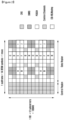
- FIG. 2 is a time-frequency grid illustrating a single Resource Block (RB) of a downlink subframe as a smallest scheduling unit in an LTE/LTE-A system.
- a radio resource is one subframe in a time domain and one RB in a frequency domain.
- the radio resource includes 12 subcarriers in the frequency domain and 14 OFDM symbols in the time domain, i.e., 168 (12 ⁇ 14) unique frequency-time positions.
- each frequency-time position is referred to as a Resource Element (RE).
- RE Resource Element
- the radio resource as illustrated in FIG. 2 can be used for transmitting a plurality of different types of signals, as follows:
- zero power CSI-RS can be configured in order for UEs within corresponding cells to receive CSI-RSs transmitted by different eNBs in an LTE-A system.
- the zero power CSI-RS (muting) can be mapped to positions designated for CSI-RSs, and the UE receives the traffic signal skipping the corresponding radio resource in general.
- the zero power CSI-RS is referred to as muting.
- the zero power CSI-RS (muting) by nature is mapped to the CSI-RS position without transmission power allocation.
- a CSI-RS can be transmitted at positions marked by A, B, C, D, E, F, G, H, I, and J, according to the number of number of antennas transmitting CSI-RS.
- the zero power CSI-RS (muting) can be mapped to positions A, B, C, D, E, F, G, H, I, and J.
- the CSI-RS can be mapped to 2, 4, or 8 REs according to the number of the antenna ports for transmission.
- a specific pattern For two antenna ports, half of a specific pattern is used for CSI-RS transmission; for four antenna ports, all of the specific pattern is used for CSI-RS transmission; and for eight antenna ports, two patterns are used for CSI-RS transmission. Muting is always performed by a pattern. That is, although the muting may be applied to according to a plurality of patterns, if the muting positions mismatch CSI-RS positions, muting cannot be applied to one pattern partially.
- the CSI-RSs When transmitting CSI-RSs of two antenna ports, the CSI-RSs are mapped to two consecutive REs in the time domain and distinguished from each other using orthogonal codes. When transmitting CSI-RSs of four antenna ports, the CSI-RSs are mapped in the same way of mapping the additional two CSI-RSs to two additional consecutive REs. A similar mapping is applied when transmitting CSI-RSs of eight antenna ports.
- an RS transmitted for downlink channel state measurement In a cellular system, an RS transmitted for downlink channel state measurement.
- a UE measures the channel state with the eNB using a CSI-RS transmitted by the eNB.
- the channel state is measured in consideration of a few factors including downlink interference.
- the downlink interference includes the interference caused by the antennas of neighbor eNBs and thermal noise, which is effective in determining a downlink channel condition. For example, when an eNB with one transmit antenna transmits an RS to a UE with one receive antenna, the UE determines an energy per symbol that can be received in a downlink (Es) and an amount of interference that may be received while receiving the corresponding symbol (Io) in order to calculate Es/lo from the received RS. The calculated Es/lo is reported to the eNB such that the eNB determines the downlink data rate for the UE.
- Es downlink
- Io corresponding symbol
- a UE feeds back the information on the downlink channel state for use in downlink scheduling of the eNB. That is, the UE measures the RS transmitted by the eNB in downlink and feeds back the information estimated from the RS to the eNB in the format defined in LTE/LTE-A standard.
- the UE feedback information includes the following three indicators:
- the RI, PMI, and CQI are associated to each other.
- a precoding matrix supported in LTE/LTE-A is configured differently per rank. Accordingly, the PMI value 'X' is interpreted differently for an Rl set to 1 and an RI set to 2.
- the UE assumes that the PMI and RI, which it has reported, are applied by the eNB. That is, if the UE reports RI_X, PMI_Y, and CQI_Z, then the UE is capable of receiving the signal at the data rate corresponding to CQI_Z, when the rank RI_X and the precoding matrix PMI_Y are applied. Accordingly, the UE calculates a CQI with which the optimal performance is achieved in a real transmission under the assumption of the transmission mode to be selected by the eNB.
- a process for configuring the CSI such as a CQI, an RI, and a PMI
- the CSI process includes a CSI-RS for channel measurement and an Interference Measurement Resource (IMR).
- the eNB may configure at least one CSI process per UE, and the UE measures a CSI-RS indicated in the CSI-RS process to acquire received signal strength of the signal passed via the channel and measures the IMR to acquire the interference strength of the received signal.
- the IMR is a radio resource that is configured separately by the eNB for a UE interference measurement, and the UE assumes that all of the signals received on the corresponding radio resource are interference.
- One IMR is configured at one of the positions A to H to which zero power CSI-RS may be applied. If the eNB configures the radio resource marked by B, as illustrated in FIG. 2 , as an IMR, the UE performs interference measurement at the resource position B in every RB.
- the number of CSI-RSs increases in proportion to the number of transmit antennas.
- an eNB transmits CSI-RSs of 8 ports to a UE for downlink channel state measurement.
- 8 REs are allocated for CSI-RS transmission in one RB.
- the REs indicated by alphabets A and B can be used for CSI-RS transmission of the corresponding eNB.
- the CSI-RS transmission resource increases in proportion to the number of transmit antennas. That is, the eNB having 128 transmit antennas transmits CSI-RS on 128 REs in one RB.
- Such a CSI-RS transmission scheme consumes excessive radio resources and thus causes shortage of resource for data transmission.
- an eNB having a plurality of transmit antennas for FD-MIMO may transmit CSI-RSs on N dimensions, such that a UE performs channel measurements for a plurality of transmit antennas without excessive resource allocation for CSI-RS transmission.
- the CSI-RSs may be transmitted in 2 dimensions.
- one CSI-RS is used as a horizontal CSI-RS for acquiring the horizontal direction channel information
- the other CSI-RS is used as a vertical CSI-RS for acquiring vertical direction channel information.
- FIG. 3 illustrates CSI-RS transmission in an FD-MIMO system according to an embodiment of the present disclosure.
- an eNB operating in an FD-MIMO mode has a total of 32 antennas 300, by way of example. That is, the number of antennas may vary depending on the embodiment.
- the 32 antennas 300 are indicated by A0, ..., A3, B0, ..., B3, C0, ..., C3, D0, ..., D3, E0, ..., E3, F0, ..., F3, G0, ..., G3, and H0, ..., H3.
- Two CSI-RSs are transmitted through the 32 antennas.
- the antenna ports corresponding to a Horizontal CSI-RS (H-CSI-RS) for use in measuring horizontal channel state includes the following 8 antenna ports.
- the expression of grouping a plurality of antennas into one CSI-RS port is a concept including antenna virtualization.
- antenna virtualization is performed using a linear combination of the plurality of antennas.
- the antenna ports corresponding to Vertical CSI-RS (V-CSI-RS) for use in measuring vertical channel state include the following 4 antenna ports.
- the plurality of antennas are arranged 2 dimensionally, as described above.
- the antennas are arranged orthogonally, forming M rows in the vertical direction and N columns in the horizontal direction.
- the UE is capable of measuring FD-MIMO channels using N H-CSI-RS ports and M V-CSI-RS ports.
- the CSI can be acquired using M+N CSI-RS ports for M ⁇ N transmit antennas. Because the channel information on a large number of transmit antennas is acquired using a relatively small number of CSI-RS ports, it is advantageous in reducing CSI-RS overhead. Although the description herein is directed to where channel information on FD-MIMO transmit antennas uses two CSI-RSs, this approach can also be applied when using more than two CSI-RSs.
- the RSs of the 32 transmit antennas are mapped to 8 H-CSI-RS ports and 4 V-CSI-RS ports, and the UE measures the radio channels using the CSI-RSs of the FD-MIMO system.
- the H-CSI-RS can be used for estimating a horizontal angle between the UE and the eNB transmit antennas, as denoted by reference number 310, while the V-CSI-RS can be used for estimating the vertical angle between the UE and the eNB transmit antennas, as denoted by reference number 320.
- the description is directed to using horizontal direction CSI and vertical direction CSI for convenience.
- an eNB operates with two or more CSI-RSs
- other types of CSI can be applied in addition to the horizontal and vertical direction CSI.
- the UE is capable of acquiring the CSI (the first CSI and the second CSI) based on the two respective CSI-RSs and the CSI (third CSI) based on both the CSI-RSs.
- the CSI corresponding to the vertical direction CSI-RS is referred to as vertical direction CSI, which includes at least one of an RI, a PMI, and a CQI, acquired based on the vertical direction CSI-RS.
- the CSI corresponding to the horizontal direction CSI-RS is referred to as horizontal direction CSI, which includes at least one of an RI, a PMI, and a CQI, acquired based on the horizontal direction CSI-RS.
- the UE When the eNB sends the UE two or more CSI-RSs, the UE is capable of transmitting the CSI corresponding to the respective CSI-RSs.
- Each of the CSI includes at least one of an RI, a PMI, and a CQI.
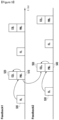
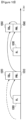
- FIG. 4 illustrates the transmission of an RI, a PMI, and a CQI, based on two CSI-RS, in a feedback method according to an embodiment of the present invention.
- a UE reports radio CSI of an FD-MIMO to an eNB by transmitting the RI, the PMI, and the CQI for the respective CSI-RSs.
- the arrows indicates how certain types of CSI are related to other types of CSI.
- the arrow 401 starting from RIv 400 and ending at the PMI v 410 indicates that the PMI v 410 is interpreted differently according to the value of RI v 400.
- the arrow 402 indicates that the UE uses the value of PMIv 410 to interpret the CQlv 420. Likewise, the UE uses the value of RI H 430 to interpret the PMI H 440, and uses the value of PMI H 440 to interpret the CQI H 450.
- the UE measures the V-CSI-RS and transmits the CSI in the method indicated as Feedback 1.
- the UE also measures the H-CSI-RS and transmits the CSI in the method indicated as Feedback 2.
- the RI, the PMI, and the CQI are transmitted as being correlated among each other.
- the RI V 400 indicates the rank of the precoding matrix indicated by PMI V 410
- the CQI V 420 indicates the data rate at which the UE can receive data or a corresponding value in the case of applying the precoding matrix of the corresponding rank which is indicated by the PMI v 410, when the transmission is performed at the rank indicated by RI V 400.
- RI H 430, PMI H 440, and CQI H 450 are transmitted as being correlated among each other, like Feedback 1.
- a CSI report method is used to configure a plurality of feedbacks for a plurality of transmit antennas of an FD-MIMO eNB and to make the UE report CSI to the eNB.
- This method is advantageous in that the UE is capable of generating and reporting CSI for FD-MIMO without extra implementation.
- the CSI report method illustrated in FIG. 4 has a shortcoming in that it is difficult to achieve sufficient throughput of the FD-MIMO system because although the UE configures a plurality of feedbacks to report the CSI to the eNB, the CQI is generated without an assumption on the precoding when the FD-MIMO is applied, as described with reference to FIG. 4 .
- both the vertical direction precoding matrix and horizontal direction precoding matrix are applied to the signal transmitted by the UE. That is, the UE receives the signal to which the precoding matrices corresponding to PMI H 440 and PMIv 410, other than the signal to which one of the PMI H 440 and PMIv 410.
- the eNB should determine the CQI to which both the vertical and horizontal direction precoding matrices are applied without receipt of such a CQI. However, when the eNB determines the CQI to which both the vertical and horizontal direction precoding matrices are applied arbitrarily, this may cause degradation of system performance.
- one of the methods for mitigating the use of radio resource for CSI-RS transmission in an FD-MIMO system is for a UE to measure a plurality of CSI-RSs capable of efficiently estimating a plurality of transmit antennas.
- Each CSI-RS can be used for the UE to measure the channel state of one of a plurality of dimensions for measuring a radio channel.
- This method uses a relatively small amount of radio resource for CSI-RS transmission, as compared to the method that allocates unique CSI-RS ports for the respective transmit antennas. For example, using two CSI-RSs in the vertical and horizontal direction for the transmit antennas of the FD-MIMO that are arranged in the form of a rectangle, the UE is capable of efficiently measuring the channel state.
- a novel technology and apparatus are provided that are capable of allowing the UE to measure a plurality of CSI-RSs and efficiently report the CSI in the FD-MIMO system including a plurality of transmit antennas.
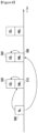
- FIG. 5 illustrates the transmission of CSI according to an embodiment of the present invention.
- FIG. 5 the CSI corresponding to the two CSI-RSs are reported similarly as described above in conjunction with FIG. 4 .
- the UE measures a V-CSI-RS to report RI V 500, PMIv 510, and CQlv 520 to the eNB in Feedback 1.
- FIG. 5 differs from FIG. 4 in that in Feedback 2, the UE reports the CQI when precoding is applied in both the vertical and horizontal directions, i.e., CQI HV 550, to the eNB.
- the UE reports the most recent PMIv 510, which is generated in the procedure indicated with Feedback 1, and CQI HV 550, which is generated when the precodings indicated by the PMI 540 that is determined optimal based on the H-CSI-RS measurement.
- the UE measures the V-CSI-RS to generate RI V 500, which is reported to the eNB.
- the UE determines an optimal PMlv 510 to the corresponding rank 500 and reports CQlv 520 when the precoding indicated by the PMIv 510 is applied.
- the UE measures an H-CSI-RS to generate RI 530, which is reported to the eNB.
- the UE reports, to the eNB, the CQI HV 550 generated by applying the precoding indicated by PMI 549, which is optimal to the corresponding rank 530, and the precoding indicated by the previously transmitted PMIv 510.
- the following may be performed.
- a function is defined for determining whether to take two PMls into consideration to determine at least one of two CQls. That is, the eNB notifies the UE of the correlation of the feedback information in configuring feedbacks to the UE, and the UE generates CQI based thereon.
- a control message instructing the UE to calculate the second CQI, i.e., CQI HV 550, by applying the first PMI, i.e., PMIv 510, and the second PMI, i.e., PMI H 540, together is transmitted from the eNB.
- a CQI is defined when applying a plurality of precodings.
- the UE calculates the CQI under an assumption that the precoding indicated by an RI and a PMI it has reported is applied in a downlink.
- the UE calculates the CQI under an assumption that two precodings are simultaneously applied in the downlink.
- the UE may interpret the application of two precodings as a Kronecker product.
- the Kronecker product is defined with two matrices as shown in Equation (1).
- a ⁇ B a 11 B ⁇ a 1 n B ⁇ ⁇ ⁇ a m 1 B ⁇ a mn B
- Equation (1) A and B denote matrices, and an to a mn denote elements of matrix A.
- a ij? denotes the element at i th row and j th column of the matrix A.
- the UE may acquire the precoding matrix when two precoding matrices are applied simultaneously by replacing A and B with the precoding matrices indicated by PMI H 540 and the PMIv 510, respectively.
- the UE calculates CQI HV 550 under the assumption that the precoding matrix acquired by applying Equation (1) to the precoding matrices indicated by the PMI H 540 and PMIv 510 is applied in the downlink.
- the UE and eNB In order to acquire the precoding matrix when the two precoding matrices are applied using the Kronecker product of Equation (1), the UE and eNB will operate differently depending on the rank reported by the UE. Herein, three different methods are proposed for this purpose.
- An eNB configures one of RI V 500 and RI H 530 with rank 1 always. For example, if CQI HV 550 is reported along with RI H 530 to the eNB, RI V 500 is restricted to be always set to 1. At this time, the rank supported when two precoding matrices are simultaneously applied is determined depending on RI H 530. That is, RI H 530 is set to 1, indicates that the UE is capable of supporting rank 1; and if RI H 530 is set to 2, this indicates that the UE is capable of supporting rank 2. The UE and the eNB operate in the FD-MIMO system under this assumption. Although two CSI-RSs are assumed in this embodiment, if the number of CSI-RS is 3 or more, RIs are set to 1, except for the RI corresponding to one CSI-RS.
- rank HV rank RI H ⁇ rank RI V
- the UE and the eNB exchange the CSI under an assumption that the rank for a case in which the vertical and horizontal direction precoding matrices are simultaneously applied is the product of the two ranks supportable in the respective directions. For example, if the UE reports the RI H set to 2 and RI V set to 3 to the eNB, the eNB and the UE assume that the rank for the case where all of the precoding matrices are applied is 6.
- the value of rank HV is a value acquired using Equation (2), with RI V and RI H transmitted from the UE to the eNB without any extra explicit signaling.
- LTE/LTE-A if the UE reports to the eNB the RI corresponding to rank 2 or higher, two CQI values are reported to the eNB. That is, because the eNB transmits two codewords to the UE and the UE reports the CQls corresponding to respective codewords, separately.
- Equation (2) When the method of Equation (2) is applied in FIG. 5 , if the rank for the case where the precodings obtained using Equation (2) is 2 or higher, although RI H 530 is set to 1, the UE transmits the two CQls in the form of CQI HV 550. Also, if the rank for the case where all of the precodings obtained by Equation (2) is 2 or higher, the eNB receives the two CQls under an assumption that they are transmitted in the form of CQI HV 550.
- the term “collision” refers to a situation requiring simultaneous transmission of Feedback 1 and Feedback 2. If collision is predicted, the UE may report the CSI of one of Feedback 1 and Feedback 2.
- the FD-MIMO operation with the configuration of a plurality of feedbacks, as illustrated in FIG. 4 or 5 may result on the CSI partially missing.
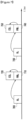
- FIG. 6 illustrates the transmission of CSI according to an embodiment of the present invention.
- the feedback method of FIG. 6 differs from FIG. 4 in that the feedback is completed in one feedback process.
- the UE transmits RI HV 600 to report the horizontal and vertical direction ranks.
- Table 1 shows exemplary horizontal and vertical direction ranks (first second ranks).
- the eNB may acquire the horizontal and vertical direction ranks from the RI HV 600 transmitted by the UE.
- the UE determines the value RI HV 600 based on both of the two CSI-RSs, i.e., H-CSI-RS and V-CSI-RS.
- the eNB checks the information on the horizontal and vertical direction precodings and UE-supportable data rate based on the PMls 610 and 630 and CQls 620 and 640 corresponding to the H-CSI-RS and V-CSI-RS. Because the horizontal and vertical direction PMls and CQls are transmitted alternately in one feedback process, it is possible to avoid the collisions of the feedback transmissions that may occur in the embodiments illustrated in FIGs. 4 and 5 .
- the horizontal and vertical direction ranks may have different values depending on the value of RI HV 600 reported by the UE. That is, the precoding matrix indicated by PMI H 610 is determined depending on the horizontal direction PMI indicated by the value of the RI HV 600. The UE also transmits a CQI obtained under an assumption of that the precoding matrix indicated by RI H 610 is applied, wherein the CQI may be CQI H 620. In order to determine the values of PMI H 610 and CQI H 620, the UE measures the H-CSI-RS. Likewise, the precoding matrix indicated by PMIv 630 is determined depending on the vertical direction rank indicated by RI HV 600. The UE also transmits a CQI obtained under an assumption that the precoding matrix indicated by PMIv 630 is applied, i.e., CQlv 640.
- the UE measures a V-CSI-RS.
- the precodings indicated by PMI H and PMIv are interpreted differently depending on the horizontal and vertical direction ranks indicated by RI HV . That is, the precoding indicated by PMI H where RI HV indicates the horizontal direction rank 1 differs from the precoding indicated by PMI H where RI HV indicates the horizontal direction rank 2.
- the UE alternately transmits the horizontal CSI 610 and 620 and the vertical CSI 630 and 640. It is also possible for the UE to alternately transmit the horizontal and vertical CSI at the same interval.
- the UE may report specific direction CSI at an interval shorter than that of the other direction CSI in view of system through optimization.
- the eNB may perform configuration thereon. That is, in the case that the UE reports different direction CSI to the eNB in one feedback process, the eNB may notifies the UE of the following information for configuration thereon.
- the subframe offset value is the value determining the subframe position for real transmission in a period. For example, if the period is 10 milliseconds (msec) and the subframe offset is 5, then the corresponding signal is transmitted at a subframe 5 in a period of 10 milliseconds.
- the horizontal and vertical direction ranks reported from the UE to the eNB may be determined depending on different rank restrictions.
- the rank restriction is to restrict, when the UE measures the RS to determine the rank, the maximum value to the value preconfigured by the eNB.
- the eNB may notify the UE of the Maximum value of horizontal direction rank and Maximum value of vertical direction rank through higher layer signaling or in another method.
- a subset of precodings that may by used by the UE may be configured for horizontal and vertical directions. Assuming that there are a set of precodings applicable to the horizontal and vertical directions, the eNB determines a subset of the set in consideration of the radio channel condition and notifies the UE of the subset. In this case, the UE selects the PMI H and PMIv in the range matching the notified subset of precodings and reports the selected PMls to the eNB.
- FIG. 7 illustrates the transmission of CSI according to another embodiment of the present invention. Specifically, in FIG. 7 , the UE reports the CSI to the eNB in one feedback process, similar to FIG. 6 . However, FIG. 7 differs from FIG. 6 in that the horizontal and vertical direction ranks are reported with RI H 700 and RI V 730 separately.
- RI H 700 is first reported and then followed by PMI H 710 and CQI H 720 based thereon.
- RI V 730 is reported and then followed by PMI V 710 and CQlv 720 based thereon.
- the RI H 700 and RI V 730 are reported separately, the intervals and ranks of the horizontal and vertical CSI may be configured differently, as in FIG. 6 .
- FIG. 8 illustrates the transmission of CSI according to another embodiment of the present invention.
- the absence of the CQI where the horizontal and vertical direction precodings are applied simultaneously may cause system performance degradation, as described above.
- the UE transmits RI HV 800 to the eNB.
- the eNB may acquire or recognize the horizontal and vertical direction ranks based on RI HV .
- the UE transmits the horizontal direction CSI including PMI H 810 and CQI H 820.
- the UE also simultaneously transmits PMI v 830 as the horizontal CSI and the CQI acquired by taking both the horizontal and vertical direction precodings into account, i.e., CQI HV .
- CQI HV 840 is acquired where the horizontal and vertical direction precodings are applied. Accordingly, the rank is also determined as a function of the horizontal and vertical direction ranks.
- the UE assumes the Kronecker product of the two precoding matrices as shown in Equation (1) as the precoding applied for generating CQI HV 840.
- the method of transmitting the horizontal and vertical direction CSI and CQI HV 840 from the UE to the eNB in a signal feedback process as illustrated in FIG. 8 makes it possible to transmit the value of CQI HV 840.
- this method has a shortcoming in that the CQI H 820 generated under the assumption of the application of only the horizontal direction precoding has a low utilization degree.
- the CQI H 820 is transmitted because the information on PMI H 810 and PMIv 830 is required for transmitting CQI assuming horizontal and vertical direction precodings, but only one of the PMIs can be reported at the timing of transmitting the CQI H 820.
- FIG. 9 illustrates the transmission of CSI according to another embodiment of the present invention.
- the UE generates CQI HV 930 under an assumption that the horizontal and vertical precoding matrices have been applied, as indicated by PMIv 900 and PMI H 920. That is, the UE generates CQI HV 930, which is transmitted with the PMI H 920 under the assumption that both the precoding matrix indicated by PMIv 900 as the most recently transmitted vertical direction precoding-related information and the precoding matrix indicated by PMI H 920 have been applied. Likewise, the UE generates CQI HV transmitted along with PMIv 940 under an assumption that both the precoding matrix indicated by PMI H 920 as the most recently transmitted horizontal direction precoding-related information and the precoding matrix indicated by PMI V 940 have been applied.
- the reason for referencing the previously transmitted PMI H or PMIv is to prevent a plurality of PMIs from being transmitted in one time duration.
- the rank is restricted in a specific direction.
- the horizontal and vertical direction precodings are updated according to the changed rank values.
- CQI HV may be transmitted after the two precodings have been updated.
- the vertical direction rank is always fixed to 1 in FIG. 9 . Because the vertical direction rank is always 1, the vertical direction rank is not changed and the UE is capable of assuming that the precoding matrix indicated by the previously transmitted PMIv and the precoding matrix indicated by PMIv are applied simultaneously.
- FIG. 9 is described where the vertical direction rank is fixed to 1, alternatively, the horizontal direction rank may be fixed to 1.
- the UE reports RI V at each RI transmission occasion, instead of RI H .
- the transmission intervals of RI, horizontal direction CSI 920 and 930, and vertical direction CSI 940 and 950 in FIG. 9 may be configured differently depending on the system environment.
- FIG. 10 illustrates the transmission of CSI according to another embodiment of the present invention.
- the UE transmits CQI HV under an assumption that horizontal and vertical direction precodings are applied at each CQI transmission occasion, similar to FIG. 9 .
- an additional RI V 1000 is transmitted to change the vertical direction rank. That is, the UE notifies the eNB of the vertical direction rank using RI V 1000 and reports PMIv 1010 based thereon.
- the CQI HV 1020 transmitted with PMIv 1010 is generated under an assumption that the precoding matrix indicated by the most recently transmitted RI and PMI and the precoding matrix indicated by the PMI V 1010 are applied.
- the UE updates the PMI 1040 based thereon and generates CQI HV 1050 under an assumption that the precoding indicated by PMIv1010 and the precoding indicated by PMI H 1040 are applied simultaneously.
- the UE may update the horizontal and vertical direction ranks separately. Accordingly, the UE calculates the rank to be assumed for generating the CSI CQI HV 1020 and 1050 using Equation (2). The UE may assume that the rank for generating CQI HV 1050 is the product of the ranks indicated by RI V 1000 and RI H 1030. Accordingly, if the product of the ranks indicated by RI V 1000 and RI H 1030 when the CQI HV 1050 is transmitted is 1, the UE transmits one CQI; and, if the product is greater than or equal to 2, the UE transmits two CQls.
- the UE transmits the CSI corresponding to at least one of the horizontal and vertical CSI-RS at an interval preconfigured by the eNB. That is, the UE transmits the CSI corresponding to the first CSI-RS at a first timing preconfigured by the eNB and the CSI corresponding to the second CSI-RS at a second timing preconfigured by the eNB. The UE may transmit the CSI generated in consideration of both the CSI-RSs at a third timing preconfigured by the eNB. According to FIG. 10 , the CSI corresponding to the horizontal direction CSI-RS and the CSI corresponding to the vertical direction CSI-RS are alternately transmitted to the eNB.
- the horizontal and vertical direction CSI may be transmitted at respective transmission intervals indicated through higher layer signaling.
- the variation of the radio channel may occur in a horizontal or vertical direction according to the movement.
- the eNB has no way of being aware of the movement direction of the UE in advance, it is difficult to secure the optimal system throughput in the way that the eNB notifies the UE of the horizontal and vertical direction CSI feedback configuration through higher layer signaling.
- a CSI indicator is provided in order for the UE to notify the eNB of the CSI-RS to which the transmitted CSI corresponds.
- the UE When the horizontal and vertical direction CSI-RSs are received, the UE generates the CSI indicator indicating the CSI-RS corresponding to the CSI which the UE is reporting.
- the CSI indicator may be expressed as a Dimension Indicator (DI).
- the DI is transmitted with or separately from the CSI and notifies the eNB of the CSI-RS corresponding to the CSI transmitted by the UE. That is, the UE uses the DI to notify the eNB whether the CSI transmitted at a certain timing has been generated based on the horizontal direction CSI-RS or the vertical CSI-RS.
- the CSI indicator may be applied where a plurality of CSI-RSs are used without the horizontal and vertical directionality concept. That is, if the eNB configures CSI-RSs in order for the UE to measure the CSI-RSs and report corresponding CSI for FD-MIMO, the UE may inform the eNB of the CSI-RS corresponding to the currently reported CSI, among the CSI-RSs, using the CSI indicator.
- FIG. 11 illustrates the transmission of CSI according to another embodiment of the present invention.
- the UE transmits DI 1100 to notify the eNB that the CSI transmitted before the next DI 1120 corresponds to the horizontal direction CSI-RS using DI 1100. That is, if the UE transmits the DI set to 0 for indicating the CSI corresponding to the horizontal direction CSI-RS, this indicates that an RI, a CQI, and a PMI transmitted before the next DI is received are the CSI corresponding to the horizontal direction CSI-RS. Otherwise, if the UE transmits the DI set to 1 for indicating the CSI corresponding to the vertical direction CSI-RS, this indicates that the RI, the CQI, and the PMI transmitted before the next DI is received are the CSI corresponding to the vertical direction CSI-RS.
- the UE transmits DIs 1100, 1120, and 1140 when transmitting the RIs 1105, 1125, and 1145, respectively.
- This method of transmitting the DI along with RI is advantageous in preventing the CSI amount from increasing significantly and reducing extra uplink overhead caused by the DI transmission. For the same reason, it is possible to transmit DI at some RI transmission occasions, i.e., not at all the RI transmission occasions. If no DI is received at an RI occasion, the eNB may assume that the CSI transmitted before receipt of a new DI are still the CSI corresponding to the CSI-RS, i.e., vertical or horizontal direction CSI-RS, indicated by the most recent DI.
- FIG. 11 applies the DI concept to the embodiment as illustrated in FIG. 7 . Accordingly, in FIG. 11 , the UE may notify the eNB of the CSI in an optimal method, in consideration of its channel condition, improving throughput as compared to the embodiment illustrated in FIG. 7 .
- FIG 12 illustrates the transmission of CSI according to an embodiment of the present invention. Specifically, FIG. 12 applies the DI concept to the embodiment illustrated in FIG. 6 .
- RI HV 1200 and 1250 is the rank indicator indicating a combination of the horizontal and vertical direction ranks.
- DI may be transmitted along with the RI HV to indicate the CSI-RS corresponding to the PMI and/or CQI transmitted before the next DI, as in FIG. 11 .
- the DI also may be transmitted with the PMI and/or CQI instead of RI HV .
- DI may indicate the CSI-RS corresponding to the PMI and/or CQI transmitted along with the DI.
- FIG. 12 illustrates where DI is transmitted with the PMI and/or CQI, at the same time.
- the UE transmits DI to indicate the CSI-RS corresponding to the PMI and CQI transmitted with the DI.
- the DI 1205 indicates that the CSI transmitted at the same time corresponds to the horizontal direction CSI-RS.
- the UE transmits PMI H 1215 and CQI H 1210 corresponding to the horizontal CSI-RS, with the DI 1205.
- DI 1220 indicates that the CSI transmitted at the same time corresponds to the vertical direction CSI-RS. Specifically, the UE transmits PMIv 1230 and CQIv 1225 with the DI 1220.
- DI 1235 indicates that the CSI transmitted at the same time corresponds to the vertical direction CSI-RS. Specifically, the UE transmits PMIv 1245 and CQIv 1240 with the DI 1235.
- the DI 1255 indicates that the CSI transmitted at the same time corresponds to the horizontal direction CSI-RS. Specifically, the UE transmits PMI H 1265 and CQI H 1260 corresponding to the horizontal CSI-RS, with the DI 1255.
- FIG. 13 illustrates the transmission of CSI according to another embodiment of the present invention. Specifically, FIG. 13 applies the DI concept to the embodiment illustrated in FIG. 10 .
- the UE transmits the DI 1300 to notify the eNB of the CSI-RS corresponding to the CSI transmitted at the same time as the DI 1300, and until a new DI, i.e., DI 1320, is received.
- the RI and PMI transmitted at the same and after may be the CSI corresponding to the horizontal or vertical CSI-RS.
- the UE transmits CQI HV 1310 generated in consideration of both the horizontal and vertical direction CSI-RSs. As described above, if the CQI HV is transmitted, the UE reports the CQI value generated in consideration of both the horizontal and vertical precodings, resulting in improved resource utilization efficiency.
- the CQI HV 1310 may be interpreted differently, with or without the presence of DI.
- the UE generates CQI HV under an assumption that the eNB has applied both the horizontal and vertical direction precoding matrices. That is, if the precoding matrix indicated by PMI H is A and the precoding matrix indicated by PHI V is B, the UE assumes that the precoding matrix, such as that shown in Equation (1), is applied by the eNB.
- a horizontal or vertical direction precoding matrix is assumed in the process of generating CQI HV depending on the value of DI.
- the UE uses the precoding matrix indicated by the most recently transmitted PMI V to obtain the precoding matrix B.
- DI indicates the direction corresponding to the precoding matrix to be updated in generating CQI.
- the UE uses the precoding matrix indicated by PMI transmitted newly in correspondence to the direction indicated by DI and, for the other direction, the precoding matrix indicated by the most recently transmitted in correspondence to the corresponding direction.
- This concept is also applicable to DI 1320, PMI H 1335, and CQI HV 1330 in the same manner.
- the DI 1340 indicates the vertical direction CSI-RS, and the UE generates CQI HV 1350 using A ⁇ B .
- the UE uses the precoding matrix indicated by PMIv 1355 transmitted in subsequence to the DI 1340 to obtain the precoding matrix B.
- the UE uses the precoding matrix indicated by the mostly recently transmitted PMI H 1335 to obtain the precoding matrix A.
- FIG. 14 illustrates the transmission of CSI according to another embodiment of the present invention.
- the horizontal RI i.e. RI H 1400 and RI H 1450 are transmitted. That is the vertical rank is fixed to 1 always. According to an alternative embodiment, only the vertical direction rank indicator may be transmitted while the horizontal direction rank indicator is fixed to 1.
- the UE transmits DI at the PMI and CQI transmission occasion, and the PMI is as one of PMI H and PMIv depending on whether the DI indicates the horizontal CSI-RS or horizontal CSI-RS.
- the UE transmits CQI HV generated in consideration of both the horizontal and vertical CSI-RSs.
- the horizontal precoding matrix indicators PMI H 1415 and 1425 are transmitted.
- the UE also uses the precoding matrix indicated by PMI H 1415 and 1430 transmitted newly in correspondence to the CSI-RS indicated by the DI to calculate CQI HV 1410 and 1425.
- the UE uses the precoding matrix indicated by the most recently transmitted PMIv in correspondence to the other direction CSI-RS.
- FIG. 15 illustrates the transmission of CSI according to another embodiment of the present invention. Specifically, FIG. 15 applies the DI concept to the embodiment illustrated in FIG. 9 . FIG. 15 differs from FIG. 14 in that the DI is transmitted at an RI transmission occasion instead of a PMI and CQI transmission occasion.
- the RI H 1500 and the RI H 1530 are transmitted in correspondence to only the horizontal direction CSI-RSs. Accordingly, the RI corresponding to the vertical direction CSI-RS is fixed to 1.
- This method of fixing the vertical direction rank to 1 is advantageous for acquiring vertical direction beamforming gain and horizontal direction spatial multiplexing gain. According to an alternative embodiment, it is possible to transmit only the vertical direction rank indicator while fixing the horizontal rank to 1.
- the UE transmits DI and then PMI corresponding to the DI, i.e., PMI H or PMlv.
- the eNB Upon receipt of DI, the eNB also processes the PMI following the DI under the assumption that the PMI is PMI H or PMlv.
- DI 1505 indicates the horizontal direction CSI-RS is transmitted, and the PMI H 1510 and 1520 indicate the horizontal direction precoding until another DI 1535 is transmitted.
- the UE uses the precoding matrix indicated by PMI H 1510 and 1520 transmitted newly in correspondence to the CSI-RS indicated by the DI.
- the UE uses the precoding matrix indicated by most recently transmitted PMI in correspondence to the corresponding other direction CSI-RS.
- the RI transmitted with DI at the same time may be fixed to one of the vertical and horizontal directions, regardless of the DI. That is, the RI always indicates the horizontal direction rank, regardless of the value of DI.
- the DI indicating different direction CSI-RS may cause a problem.
- the UE notifies the eNB that the horizontal direction RI is changed using RI H 1530.
- DI 1535 indicates the vertical direction CSI-RS
- the eNB is not notified of the horizontal direction precoding information with PMIv 1540. In order to overcome this problem, two approaches are considered.
- Approach 1 When only the horizontal direction RI is transmitted, if the DI indicates the vertical direction CSI-RS, the UE sets the corresponding RI to the value of the previously transmitted RI without change. That is, if the DI indicates the horizontal direction CSI-RS as DI 1535, the UE transmits the RI H 1530 equal to the previous RI H 1500 to the eNB. The UE also determines CQI HV 1545 and 1555 under an assumption that the PMIv 1540 and 1550 and the most recently transmitted PMI H 1520 indicate the same precoding matrix.
- Approach 2 When only the horizontal direction RI is transmitted, the UE transmits the horizontal PMI and CQI at PMI/CQI transmission timing, after the RI transmission timing.
- the UE configures DI indicating vertical direction CSI-RS, it transmits the horizontal direction PMI and CQI first and then the vertical direction PMI and CQI afterward. This prevents the PMIv from being transmitted right after the RI in order to solve the aforementioned problem.
- a method for the UE to efficiently report the CSI to the eNB using a plurality of transmit antennas, such as in FD-MIMO.
- the eNB should configure the CSI feedback to the UE. That is, the UE has to have the capability of determining whether to report the CSI to the eNB in a conventional method or to measure a plurality of CSI-RSs and report the information, such as CQI HV (which is not supported in the conventional method), using the new methods illustrated in FIGs. 8 and 9 .
- a method is provided for the UE to make such a determination based on the CSI process configuration.
- the CSI process specified in the conventional technology consists of one CSI-RS and one IMR.
- the CSI process includes a plurality of CSI-RSs and one IMR.
- the UE determines whether to apply the new CSI report method depending on the number of CSI-RSs included in the CSI process, without extra control information from the eNB.
- the CSI report scheme based on the number of CSI-RSs included the CSI process is summarized by the UE measuring one CSI-RS to report the corresponding CQI, when the number of CSI-RSs included in the CSI-RS process is 1, and the UE measuring two CSI-RSs to report CQI HV , when the number of CSI-RSs included in the CSI-RS process is 2.
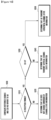
- FIG. 16 is flowchart illustrating an eNB procedure for receiving CSI according to an embodiment of the present invention.
- the eNB checks the number and 2-dimensional arrangement state of the transmit antennas of the FD-MIMO transmitter in step 1600.
- the eNB determines, based on the check result, the configuration of the CSI-RS H and CSI-RSv.
- various embodiments of the present disclosure have proposed the CSI-RS H and CSI-RSv configurations, other types of first and second CSI-RSs may be configured in alternative embodiments.
- the CSI-RS H and CSI-RSv configuration is notified to the UE through higher layer signaling or in another method.
- the eNB also notifies the UE of the CSI feedback configuration in which the UE feeds back the CSI corresponding to CSI-RS H and CSI-RSv. This configuration is transmitted from the eNB to the UE through higher layer signaling.
- the CSI feedback configuration may be provided to the UE in another method.
- the eNB determines whether it is a DI reception timing in step 1610. If it is not the DI reception timing, the eNB determines that the UE is transmitting the CSI generated based on the previously indicated CSI-RS in step 1620. However, if it is the DI reception timing in step 1610, the eNB receives the DI and determines whether the DI indicates the horizontal direction CSI-RS or the vertical direction CSI-RS in step 1630. If the DI indicates the horizontal direction CSI-RS, the eNB performs control operations, such as scheduling on the UE under an assumption of the horizontal direction CSI in step 1650.
- the eNB performs control operations, such as scheduling on the UE under an assumption of the vertical direction CSI in step 1640.
- Such CSI reception at operations 1640 and 1650 is maintained until new DI is received.
- FIG. 17 is a flowchart illustrating a UE procedure for transmitting CSI according to an embodiment of the present invention.
- the UE receives the control information associated with the measurement of a plurality of CSI-RSs for an FD-MIMO system from the eNB. That is, the UE receives the information on how to receive the CSI-RS H and CSI-RSv transmitted by the eNB.
- the UE also receives the CSI feedback configuration indicating how the UE should feed back the CSI corresponding to CSI-RS H and CSI-RSv. This configuration is transmitted from the eNB to the UE through higher layer signaling.
- the CSI feedback configuration may be provided to the UE in another method. The UE transmits the CSI according to the CSI feedback configuration.
- the UE determines whether it is a DI transmission timing. If it is not DI transmission timing in step 1710, the UE transmits the CSI generated based on the previously indicated CSI-RS in step 1720. However, if it is the DI transmission timing in step 1710, the UE transmits the DI indicating the horizontal or vertical direction CSI-RS corresponding to the CSI in step 1730. For example, the UE determines the CSI-RS for use in generating the CSI according to the change in its movement or the recent channel state and transmits the DI corresponding to the determined CSI-RS to the eNB. If the DI is set to indicate the horizontal direction CSI-RS, the UE transmits the horizontal direction CSI in step 1750.
- the UE transmits the vertical direction CSI in step 1740.
- the CSI transmission step 1740 and 1750 are maintained until a new DI is transmitted.
- Detailed examples of CSI generation and transmission methods have been provided above with reference to FIGs. 5 to 15 .
- FIGs. 16 and 17 illustrate the eNB transmitting CSI-RS and CSI feedback configuration explicitly
- the present invention may be embodied in such a way that the eNB notifies the UE of at least one of CSI-RS transmission position of the eNB, number of CSI-RSs, and number of ports per CSI-RS, and the UE generates and transmits the CSI according to a feedback configuration predetermined based on the received information. It is sufficient for the eNB to provide the UE with the information necessary for determining the CSI generation and transmission method.
- FIG. 18 is a block diagram illustrating an eNB according to an embodiment of the present invention.
- the eNB includes a controller 1800, a transmitter 1810, and a receiver 1820.
- the controller 1800 e.g., a microprocessor, determines the configuration on the plurality of CSI-RSs.
- the controller 1800 may determine the CSI-RS transmission scheme and the corresponding CSI generation and feedback scheme.
- the transmitter 1810 transmits the determination result to the UE.
- the transmitter 1810 transmits the plurality of CSI-RSs to the UE.
- the receiver 1820 receives the CSI corresponding to the CSI-RSs from the UE. Examples of the eNB procedure for receiving CSI have been described above with reference to FIGs. 5 to 17 .
- the controller 1800 receives the CSI at the CSI indicator (e.g., DI) reception timing and, afterward, assumes that the CSI received before the receipt of a new CSI indicator corresponds to the CSI-RS indicated by the CSI indicator and uses the CSI for scheduling.
- the CSI indicator e.g., DI
- FIG. 19 is a block diagram illustrating a UE according to an embodiment of the present invention.
- the UE includes a controller 1900. a transmitted 1910, and a receiver 1920.
- the receiver 1920 receives the configuration information on a plurality of CSI-RSs and a CSI generation and feedback scheme.
- the controller 1900 controls the receiver 1920 to receive the plurality of CSI-RSs transmitted by the eNB.
- the controller 1900 generates CSI based on the plurality of CSI-RSs and controls the transmitter 1910 to transmit the CSI to the eNB. Examples of UE procedures for transmitting CSI have been described above with reference to FIGs. 5 to 17 .
- the controller 1900 transmits the CSI at the CSI (e.g., DI) transmission timing and, afterward, transmits the CSI corresponding to the CSI-RS indicated by the CSI indicator until the transmission of a new CSI indicator.
- CSI e.g., DI
- each block of the flowchart illustrations and/or block diagrams, and combinations of blocks in the flowchart illustrations and/or block diagrams can be implemented by computer program instructions. These computer program instructions may be provided to a processor of a general purpose computer, special purpose computer, or other programmable data processing apparatus to produce a machine, such that the instructions, which are executed via the processor of the computer or other programmable data processing apparatus, implement functions/acts specified in the flowchart and/or block diagram block or blocks.
- These computer program instructions may also be stored in a computer-readable memory that can direct a computer or other programmable data processing apparatus to function in a particular manner, such that the instructions stored in the computer-readable memory produce an article of manufacture including instruction means which implement the function/act specified in the flowchart and/or block diagram block or blocks.
- the computer program instructions may also be loaded onto a computer or other programmable data processing apparatus to cause a series of operational steps to be performed on the computer or other programmable apparatus to produce a computer implemented process such that the instructions which execute on the computer or other programmable apparatus provide steps for implementing the functions/acts specified in the flowchart and/or block diagram block or blocks.
- the respective block diagrams may illustrate parts of modules, segments or codes including at least one or more executable instructions for performing specific logic function(s).
- the functions of the blocks may be performed in different order in several modifications. For example, two successive blocks may be performed substantially at the same time, or may be performed in reverse order according to their functions.
- module means, but is not limited to, a software or hardware component, such as a Field Programmable Gate Array (FPGA) or Application Specific Integrated Circuit (ASIC), which performs certain tasks.
- a module may advantageously be configured to reside on the addressable storage medium and configured to be executed on one or more processors.
- a module may include, by way of example, components, such as software components, object-oriented software components, class components and task components, processes, functions, attributes, procedures, subroutines, segments of program code, drivers, firmware, microcode, circuitry, data, databases, data structures, tables, arrays, and variables.
- the functionality provided for in the components and modules may be combined into fewer components and modules or further separated into additional components and modules.
- the components and modules may be implemented such that they execute one or more CPUs in a device or a secure multimedia card.
Description
- The present invention relates generally to a Channel State Information (CSI) transmission and reception method and apparatus and, in particular, to a method and apparatus for transmitting and receiving CSI in a wireless communication system using a plurality of antennas.
- A Reference Signal (RS) is used in measuring a channel state or quality, such as signal strength and distortion, interference strength, and Gaussian noise, between a Base Station (BS) and User Equipments (UEs) (or terminals) and demodulating and decoding a received data symbol in a wireless mobile communication system. The RS is also used to measure a radio channel state. For example, a receiver measures a strength of an RS transmitted by a transmitter at a predetermined transmit power in order to determine a radio channel state between the receiver and the transmitter. Thereafter, the receiver requests a data rate from the transmitter, based on the determined radio channel state.
- The 3rd generation evolved mobile communication standards, such as the 3rd Generation Partnership Project Long Term Evolution-Advanced (3GPP LTE-A) and Institute of Electrical and Electronics Engineers (IEEE) 802.16m, have adopted multi-carrier multiple access techniques such as Orthogonal Frequency Division Multiplexing (OFDM) or Orthogonal Frequency Division Multiple Access (OFDMA).
- In a multi-carrier multiple access-based wireless mobile communication system, channel estimation and measurement performance is influenced by the number of symbols and number of subcarriers to which an RS is mapped on a time-frequency resource grid. The channel estimation and measurement performance is also influenced by the power allocated for the RS transmission. Accordingly, by allocating more radio resources (including time, frequency, and power), it is possible to improve channel estimation and measurement performance, thereby improving received data symbol demodulation and decoding performance and channel state measurement accuracy.
- In a resource-constrained mobile communication system, however, if a radio resource is allocated for transmitting RSs, this reduces the available resources for data signal transmission. Accordingly, an amount of resources for RS transmission should be determined appropriately, by taking the system throughput into account.
-
WO 2011/100672 A1 discloses a system and method of receiving a channel state information reference signal (CSI-RS). At a user equipment, a first CSI-RS transmitted from a base station is received. In some implementations, the first CSI-RS is transmitted at a first periodicity using a first set of antenna ports. At the user equipment, a second CSI-RS transmitted from the base station is received. In some implementations, the second CSI-RS is transmitted at a second periodicity using a second set of antenna ports. At least one of the first CSI-RS and the second CSI-RS is used to perform channel measurement. -
US 2012/076028 A1 discloses a method for transmitting channel status information (CSI) of downlink multi-carrier transmission which includes generating the CSI including at least one of a rank indicator (RI), a first precoding matrix index (PMI), a second PMI and a channel quality indicator (CQI) for one or more downlink carriers, the CQI being calculated based on precoding information determined by a combination of the first and second PMls, determining, when two or more CSIs collide with one another in one uplink subframe of one uplink carrier, a CSI to be transmitted on the basis of priority, and transmitting the determined CSI over a uplink channel. If a CSI including an RI or a wideband first PMI collides with a CSI including a wideband CQI or a subband CQI, the CSI including a wideband CQI or a subband CQI has low priority and is dropped. - The present invention is set out in the independent claims whereas preferred embodiments and further implementations are outlined in the dependent claims, description and figures.
- In accordance with the above-described embodiments of the present invention, the CSI transmission and reception methods are capable of efficiently transmitting the CSI in the system using a plurality of antennas.
- The above and other aspects, features, and advantages of certain embodiments of the present invention will be more apparent from the following detailed description taken in conjunction with the accompanying drawings, in which:
-
FIG. 1 illustrates a Full Dimension MIMO (FD-MIMO) system; -
FIG. 2 is a time-frequency grid illustrating a single Resource Block (RB) of a downlink subframe as a smallest scheduling unit in an LTE/LTE-A system; -
FIG. 3 illustrates CSI-RS transmission in an FD-MIMO system according to an embodiment of the present invention; -
FIG. 4 illustrates the transmission of a Rank Indicator (RI), a Precoding Matrix Indicator (PMI), and a Chanel Quality Index (CQI), based on two CSI-RS, in a feedback method according to an embodiment of the present invention; -
FIG. 5 illustrates the transmission of CSI according to an embodiment of the present invention; -
FIG. 6 illustrates the transmission of CSI according to an embodiment of the present invention; -
FIG. 7 illustrates the transmission of CSI according to another embodiment of the present invention; -
FIG. 8 illustrates the transmission of CSI according to another embodiment of the present invention; -
FIG. 9 illustrates the transmission of CSI according to another embodiment of the present invention; -
FIG. 10 illustrates the transmission of CSI according to another embodiment of the present invention; -
FIG. 11 illustrates the transmission of CSI according to another embodiment of the present invention; -
FIG 12 illustrates the transmission of CSI according to an embodiment of the present invention; -
FIG. 13 illustrates the transmission of CSI according to another embodiment of the present invention; -
FIG. 14 illustrates the transmission of CSI according to another embodiment of the present invention; -
FIG. 15 illustrates the transmission of CSI according to another embodiment of the present invention; -
FIG. 16 is flowchart illustrating an enhanced Node B (eNB) procedure for receiving CSI according to an embodiment of the present invention; -
FIG. 17 is a flowchart illustrating a UE procedure for transmitting CSI according to an embodiment of the present invention; -
FIG. 18 is a block diagram illustrating an eNB according to an embodiment of the present invention; and -
FIG. 19 is a block diagram illustrating a UE according to an embodiment of the present invention. - The invention is defined by the appended claims.
- Various embodiments of the present disclosure are described with reference to the accompanying drawings in detail. However, detailed descriptions of well-known functions and structures incorporated herein may be omitted to avoid obscuring the subject matter of the present disclosure. Further, the following terms are defined in consideration of the functionality in the present disclosure, and may vary according to the intention of a user or an operator, usage, etc. Therefore, the definition should be made on the basis of the overall content of the present specification.
- Although the following description is directed to an OFDM-based radio communication system, particularly, a 3GPP Evolved Universal Terrestrial Radio Access (E-UTRA) system, it will be understood by those skilled in the art that the various embodiments of the present invention can be applied to other communication systems having similar technical backgrounds and channel formats, with slight modifications, without departing from the scope of the present invention.
- Existing 3rd and 4th Generation mobile communication systems represented by LTE/LTE-A use a MIMO scheme with a plurality of transmit and receive antennas to transmit a plurality of information streams that are spatially separated. The technique of transmitting the spatially separated information streams is referred to as spatial multiplexing. Typically, the number of information streams that can be spatially multiplexed depends on the number of antennas of the transmitter and the receiver. Further, the number of information streams that can be spatially multiplexed is referred to as "a rank". For a MIMO scheme up to LTE/LTE-A Release 11, spatial multiplexing of up to 8 × 8 antennas and up to rank 8 are supported.
- An FD-MIMO system, to which embodiments of the present invention will be described, is a wireless communication system capable of transmitting data using 32 or more transmit antennas and evolved from the LTE/LTE-A MIMO system supporting up to 8 transmit antennas. However, the scope of the present invention is not limited thereto.
-
FIG. 1 illustrates an FD-MIMO system. - Referring to
FIG. 1 , aBS transmitter 100 transmitsradio signals antennas 110. Thetransmit antennas 110 are arranged at minimum distance among each other. For example, the minimum distance may be half of a wavelength (λ/2). Typically, when thetransmit antennas 110 are arranged at the distance of half of the wavelength of the radio signal, the signals transmitted by the respective transmit antennas are influenced by radio channel with low correlation. Assuming a radio signal band of 2GHz, the distance is 7.5 cm, and is shortened as the band becomes higher than 2GHz. - In
FIG. 1 , the transmitantennas 110 arranged at theBS transmitter 100 are used to transmit signals to one ormore terminals - In order to simultaneously transmit signals to a plurality terminals, an appropriated precoding is applied.
- A terminal may receive a plurality of information streams. Typically, the number of information streams that a terminal can receive is determined depending on the number of receive antennas of the terminal, a channel state, and a reception capability of the terminal.
- In order to efficiently implement the FD-MIMO system, a terminal should accurately measure the channel condition and interference size, and transmit the CSI to the BS efficiently.
- If the CSI is received, the BS determines the terminals for downlink transmission, downlink data rates, and precoding to be applied. For an FD-MIMO system using large number of transmit antennas, if the CSI transmission method of the legacy LTE/LTE-A system is applied without modification, the amount of control information to be transmitted in an uplink increases significantly, increasing uplink overhead.
- The mobile communication system is restricted in resources such as time, frequency, and transmission power. Accordingly, if the resources allocated for RSs increase, the amount of resources that may be allocated for data traffic channel transmission decreases, thereby reducing the amount of data transmission. In this case, although channel estimation and measurement performance are improved, the amount of data transmission decreases, thereby reducing the system throughput. Thus, it is important to efficiently allocate resources for RS and traffic channel transmissions, in order to maximize system throughput.
-
FIG. 2 is a time-frequency grid illustrating a single Resource Block (RB) of a downlink subframe as a smallest scheduling unit in an LTE/LTE-A system. Referring toFIG. 2 , a radio resource is one subframe in a time domain and one RB in a frequency domain. The radio resource includes 12 subcarriers in the frequency domain and 14 OFDM symbols in the time domain, i.e., 168 (12 × 14) unique frequency-time positions. In LTE/LTE-A, each frequency-time position is referred to as a Resource Element (RE). - The radio resource as illustrated in
FIG. 2 can be used for transmitting a plurality of different types of signals, as follows: - 1. A Cell-specific Reference Signal (CRS): an RS transmitted to all UEs within a cell;
- 2. a DeModulation Reference Signal (DMRS): an RS transmitted to a specific UE;
- 3. a Physical Downlink Shared CHannel (PDSCH): a data channel transmitted in a downlink, which an eNB uses to transmit data to the UE, and mapped to REs not used for RS transmission in a data region, as illustrated in
FIG. 2 ; - 4. a CSI Reference Signal (CSI-RS): an RS transmitted to UEs within a cell and used for channel state measurement. Multiple CSI-RSs can be transmitted within a cell; and
- 5. Other control channels (e.g., Physical Hybrid-ARQ Indicator CHannel (PHICH), Physical Control Format Indicator CHannel (PCFICH), and Physical Downlink Control CHannel (PDCCH)): channels for providing control channels for the UE to receive PDCCH and transmitting ACKnowledgement/Negative ACKnowledgement (ACK/NACK) of Hybrid Automatic Repeat reQuest (HARQ) operations for uplink data transmission.
- In addition to the above-described signals and channels, zero power CSI-RS can be configured in order for UEs within corresponding cells to receive CSI-RSs transmitted by different eNBs in an LTE-A system. The zero power CSI-RS (muting) can be mapped to positions designated for CSI-RSs, and the UE receives the traffic signal skipping the corresponding radio resource in general. In the LTE-A system, the zero power CSI-RS is referred to as muting. The zero power CSI-RS (muting) by nature is mapped to the CSI-RS position without transmission power allocation.
- In
FIG. 2 , a CSI-RS can be transmitted at positions marked by A, B, C, D, E, F, G, H, I, and J, according to the number of number of antennas transmitting CSI-RS. Also, the zero power CSI-RS (muting) can be mapped to positions A, B, C, D, E, F, G, H, I, and J. The CSI-RS can be mapped to 2, 4, or 8 REs according to the number of the antenna ports for transmission. - For two antenna ports, half of a specific pattern is used for CSI-RS transmission; for four antenna ports, all of the specific pattern is used for CSI-RS transmission; and for eight antenna ports, two patterns are used for CSI-RS transmission. Muting is always performed by a pattern. That is, although the muting may be applied to according to a plurality of patterns, if the muting positions mismatch CSI-RS positions, muting cannot be applied to one pattern partially.
- When transmitting CSI-RSs of two antenna ports, the CSI-RSs are mapped to two consecutive REs in the time domain and distinguished from each other using orthogonal codes. When transmitting CSI-RSs of four antenna ports, the CSI-RSs are mapped in the same way of mapping the additional two CSI-RSs to two additional consecutive REs. A similar mapping is applied when transmitting CSI-RSs of eight antenna ports.
- In a cellular system, an RS transmitted for downlink channel state measurement. In a 3GPP LTE-A system, a UE measures the channel state with the eNB using a CSI-RS transmitted by the eNB. The channel state is measured in consideration of a few factors including downlink interference. The downlink interference includes the interference caused by the antennas of neighbor eNBs and thermal noise, which is effective in determining a downlink channel condition. For example, when an eNB with one transmit antenna transmits an RS to a UE with one receive antenna, the UE determines an energy per symbol that can be received in a downlink (Es) and an amount of interference that may be received while receiving the corresponding symbol (Io) in order to calculate Es/lo from the received RS. The calculated Es/lo is reported to the eNB such that the eNB determines the downlink data rate for the UE.
- In an LTE-A system, a UE feeds back the information on the downlink channel state for use in downlink scheduling of the eNB. That is, the UE measures the RS transmitted by the eNB in downlink and feeds back the information estimated from the RS to the eNB in the format defined in LTE/LTE-A standard. In LTE/LTE-A, the UE feedback information includes the following three indicators:
- 1. a Rank Indicator (RI): an indicator of the number of spatial layers that can be supported by a current channel experienced at a UE;
- 2. a Precoding Matrix Indicator (PMI): an indicator of a precoding matrix recommended by a current channel experienced at a UE; and
- 3. a Channel Quality Indicator (CQI): an indicator of a maximum possible data rate that a UE can receive a signal at in a current channel state. The CQI may be replaced with a Signal-to-Interference-Noise Ratio (SINR), a maximum error correction code rate, and a modulation scheme, or a per-frequency data efficiency that can be used in similar way to the maximum data rate.
- The RI, PMI, and CQI are associated to each other. For example, a precoding matrix supported in LTE/LTE-A is configured differently per rank. Accordingly, the PMI value 'X' is interpreted differently for an Rl set to 1 and an RI set to 2. Also, when determining a CQI, the UE assumes that the PMI and RI, which it has reported, are applied by the eNB. That is, if the UE reports RI_X, PMI_Y, and CQI_Z, then the UE is capable of receiving the signal at the data rate corresponding to CQI_Z, when the rank RI_X and the precoding matrix PMI_Y are applied. Accordingly, the UE calculates a CQI with which the optimal performance is achieved in a real transmission under the assumption of the transmission mode to be selected by the eNB.
- In LTE/LTE-A, a process for configuring the CSI, such as a CQI, an RI, and a PMI, to the UE is defined as "a CSI process". The CSI process includes a CSI-RS for channel measurement and an Interference Measurement Resource (IMR). The eNB may configure at least one CSI process per UE, and the UE measures a CSI-RS indicated in the CSI-RS process to acquire received signal strength of the signal passed via the channel and measures the IMR to acquire the interference strength of the received signal. The IMR is a radio resource that is configured separately by the eNB for a UE interference measurement, and the UE assumes that all of the signals received on the corresponding radio resource are interference. One IMR is configured at one of the positions A to H to which zero power CSI-RS may be applied. If the eNB configures the radio resource marked by B, as illustrated in
FIG. 2 , as an IMR, the UE performs interference measurement at the resource position B in every RB. - Typically, in FD-MIMO using a plurality of transmit antennas, the number of CSI-RSs increases in proportion to the number of transmit antennas. For example, in an LTE/LTE-A system using 8 transmit antennas, an eNB transmits CSI-RSs of 8 ports to a UE for downlink channel state measurement. In order to transmit 8-port CSI-RSs, 8 REs are allocated for CSI-RS transmission in one RB. For example, the REs indicated by alphabets A and B can be used for CSI-RS transmission of the corresponding eNB. When applying a CSI-RS transmission scheme of LTE/LTE-A to FD-MIMO, the CSI-RS transmission resource increases in proportion to the number of transmit antennas. That is, the eNB having 128 transmit antennas transmits CSI-RS on 128 REs in one RB. Such a CSI-RS transmission scheme consumes excessive radio resources and thus causes shortage of resource for data transmission.
- Alternatively, an eNB having a plurality of transmit antennas for FD-MIMO may transmit CSI-RSs on N dimensions, such that a UE performs channel measurements for a plurality of transmit antennas without excessive resource allocation for CSI-RS transmission. For example, referring again to
FIG. 1 , where the transmitantennas 110 of the eNB are arranged 2-dimensionally, the CSI-RSs may be transmitted in 2 dimensions. In this case, one CSI-RS is used as a horizontal CSI-RS for acquiring the horizontal direction channel information, while the other CSI-RS is used as a vertical CSI-RS for acquiring vertical direction channel information. -
FIG. 3 illustrates CSI-RS transmission in an FD-MIMO system according to an embodiment of the present disclosure. - Referring to
FIG. 3 , an eNB operating in an FD-MIMO mode has a total of 32antennas 300, by way of example. That is, the number of antennas may vary depending on the embodiment. - More specifically, in
FIG. 3 , the 32antennas 300 are indicated by A0, ..., A3, B0, ..., B3, C0, ..., C3, D0, ..., D3, E0, ..., E3, F0, ..., F3, G0, ..., G3, and H0, ..., H3. Two CSI-RSs are transmitted through the 32 antennas. The antenna ports corresponding to a Horizontal CSI-RS (H-CSI-RS) for use in measuring horizontal channel state includes the following 8 antenna ports. - 1. H-CSI-RS port 0: group of antennas A0, A1, A2, and A3
- 2. H-CSI-RS port 1: group of antennas B0, B1, B2, and B3
- 3. H-CSI-RS port 2: group of antennas C0, C1, C2, and C3
- 4. H-CSI-RS port 3: group of antennas D0, D1, D2, and D3
- 5. H-CSI-RS port 4: group of antennas E0, E1, E2, and E3
- 6. H-CSI-RS port 5: group of antennas F0, F1, F2, and F3
- 7. H-CSI-RS port 6: group of antennas G0, G1, G2, and G3
- 8. H-CSI-RS port 7: group of antennas H0, H1, H2, and H3
- The expression of grouping a plurality of antennas into one CSI-RS port is a concept including antenna virtualization. Typically, antenna virtualization is performed using a linear combination of the plurality of antennas. The antenna ports corresponding to Vertical CSI-RS (V-CSI-RS) for use in measuring vertical channel state include the following 4 antenna ports.
- 1. V-CSI-RS port 0: group of antennas A0, B0, C0, D0, E0, F0, G0, and H0
- 2. V-CSI-RS port 1: group of antennas A1, B1, C1, D1, E1, F1, G1, and H1
- 3. V-CSI-RS port 2: group of antennas A2, B2, C2, D2, E2, F2, G2, and H2
- 4. V-CSI-RS port 3: group of antennas A3, B3, C3, D3, E3, F3, G3, and H3
- It is assumed, herein, that the plurality of antennas are arranged 2 dimensionally, as described above. The antennas are arranged orthogonally, forming M rows in the vertical direction and N columns in the horizontal direction. In this case, the UE is capable of measuring FD-MIMO channels using N H-CSI-RS ports and M V-CSI-RS ports.
- As described above, if two CSI-RSs are used, the CSI can be acquired using M+N CSI-RS ports for M×N transmit antennas. Because the channel information on a large number of transmit antennas is acquired using a relatively small number of CSI-RS ports, it is advantageous in reducing CSI-RS overhead. Although the description herein is directed to where channel information on FD-MIMO transmit antennas uses two CSI-RSs, this approach can also be applied when using more than two CSI-RSs.
- In
FIG. 3 , the RSs of the 32 transmit antennas are mapped to 8 H-CSI-RS ports and 4 V-CSI-RS ports, and the UE measures the radio channels using the CSI-RSs of the FD-MIMO system. The H-CSI-RS can be used for estimating a horizontal angle between the UE and the eNB transmit antennas, as denoted byreference number 310, while the V-CSI-RS can be used for estimating the vertical angle between the UE and the eNB transmit antennas, as denoted byreference number 320. - For clarity, the following abbreviations will be used throughout the specification.
- RIH: an RI generated based on an H-CSI-RS for feedback to an eNB.
- RIV: an RI generated based on a V-CSI-RS for feedback to an eNB.
- RIHV: an RI generated based on an H-CSI-RS and a V-CSI-RS for feedback to an eNB.
- PMIH: a PMI generated based on an H-CSI-RS for feedback to an eNB.
- PMIV: a PMI generated based on a V-CSI-RS for feedback to an eNB.
- CQIH: a UE-recommended data rate generated under an assumption that only a horizontal direction precoding matrix is applied.
- CQlv: a UE-recommended data rate generated under an assumption that only a vertical precoding matrix is applied.
- CQIHV: a UE-recommended data rate generated under an assumption that both horizontal and vertical precoding matrices are applied.
- The description is directed to using horizontal direction CSI and vertical direction CSI for convenience. However, when an eNB operates with two or more CSI-RSs, other types of CSI can be applied in addition to the horizontal and vertical direction CSI. For example, when a CSI-RS mapped to an antenna port from a first view point (a first CSI-RS) and a CSI-RS mapped to an antenna port from a second view point (a second CSI-RS) are used, the UE is capable of acquiring the CSI (the first CSI and the second CSI) based on the two respective CSI-RSs and the CSI (third CSI) based on both the CSI-RSs.
- The configuration described in the following description is applicable to various embodiments in similar manner.
- In the following description, the CSI corresponding to the vertical direction CSI-RS is referred to as vertical direction CSI, which includes at least one of an RI, a PMI, and a CQI, acquired based on the vertical direction CSI-RS. Further, the CSI corresponding to the horizontal direction CSI-RS is referred to as horizontal direction CSI, which includes at least one of an RI, a PMI, and a CQI, acquired based on the horizontal direction CSI-RS.
- When the eNB sends the UE two or more CSI-RSs, the UE is capable of transmitting the CSI corresponding to the respective CSI-RSs. Each of the CSI includes at least one of an RI, a PMI, and a CQI.
-
FIG. 4 illustrates the transmission of an RI, a PMI, and a CQI, based on two CSI-RS, in a feedback method according to an embodiment of the present invention. Specifically, a UE reports radio CSI of an FD-MIMO to an eNB by transmitting the RI, the PMI, and the CQI for the respective CSI-RSs. Referring toFIG. 4 , the arrows indicates how certain types of CSI are related to other types of CSI. Specifically, thearrow 401 starting fromRIv 400 and ending at thePMI v 410 indicates that thePMI v 410 is interpreted differently according to the value ofRI v 400. That is, thearrow 402 indicates that the UE uses the value ofPMIv 410 to interpret theCQlv 420. Likewise, the UE uses the value ofRI H 430 to interpret thePMI H 440, and uses the value ofPMI H 440 to interpret theCQI H 450. - In
FIG. 4 , the UE measures the V-CSI-RS and transmits the CSI in the method indicated asFeedback 1. The UE also measures the H-CSI-RS and transmits the CSI in the method indicated asFeedback 2. Here, the RI, the PMI, and the CQI are transmitted as being correlated among each other. ForFeedback 1, theRI V 400 indicates the rank of the precoding matrix indicated byPMI V 410, and theCQI V 420 indicates the data rate at which the UE can receive data or a corresponding value in the case of applying the precoding matrix of the corresponding rank which is indicated by thePMI v 410, when the transmission is performed at the rank indicated byRI V 400. ForFeedback 2,RI H 430,PMI H 440, andCQI H 450 are transmitted as being correlated among each other, likeFeedback 1. - As illustrated in
FIG. 4 , a CSI report method is used to configure a plurality of feedbacks for a plurality of transmit antennas of an FD-MIMO eNB and to make the UE report CSI to the eNB. This method is advantageous in that the UE is capable of generating and reporting CSI for FD-MIMO without extra implementation. - However, the CSI report method illustrated in
FIG. 4 has a shortcoming in that it is difficult to achieve sufficient throughput of the FD-MIMO system because although the UE configures a plurality of feedbacks to report the CSI to the eNB, the CQI is generated without an assumption on the precoding when the FD-MIMO is applied, as described with reference toFIG. 4 . - When a plurality of transmit antennas of an FD-MIMO system are arranged 2-dimentinally, as illustrated in
FIG. 3 , both the vertical direction precoding matrix and horizontal direction precoding matrix are applied to the signal transmitted by the UE. That is, the UE receives the signal to which the precoding matrices corresponding toPMI H 440 andPMIv 410, other than the signal to which one of thePMI H 440 andPMIv 410. - If
only CQI H?450 and CQIv420 corresponding to precodings indicated by therespective PMI H 440 andPMIv 410 are reported to the eNB, the eNB should determine the CQI to which both the vertical and horizontal direction precoding matrices are applied without receipt of such a CQI. However, when the eNB determines the CQI to which both the vertical and horizontal direction precoding matrices are applied arbitrarily, this may cause degradation of system performance. - As described above, one of the methods for mitigating the use of radio resource for CSI-RS transmission in an FD-MIMO system is for a UE to measure a plurality of CSI-RSs capable of efficiently estimating a plurality of transmit antennas. Each CSI-RS can be used for the UE to measure the channel state of one of a plurality of dimensions for measuring a radio channel. This method uses a relatively small amount of radio resource for CSI-RS transmission, as compared to the method that allocates unique CSI-RS ports for the respective transmit antennas. For example, using two CSI-RSs in the vertical and horizontal direction for the transmit antennas of the FD-MIMO that are arranged in the form of a rectangle, the UE is capable of efficiently measuring the channel state. In accordance with an embodiment of the present invention a novel technology and apparatus are provided that are capable of allowing the UE to measure a plurality of CSI-RSs and efficiently report the CSI in the FD-MIMO system including a plurality of transmit antennas.
-
FIG. 5 illustrates the transmission of CSI according to an embodiment of the present invention. - Referring to
FIG. 5 , the CSI corresponding to the two CSI-RSs are reported similarly as described above in conjunction withFIG. 4 . The same as inFIG. 1 , the UE measures a V-CSI-RS to reportRI V 500,PMIv 510, andCQlv 520 to the eNB inFeedback 1. However,FIG. 5 differs fromFIG. 4 in that inFeedback 2, the UE reports the CQI when precoding is applied in both the vertical and horizontal directions, i.e.,CQI HV 550, to the eNB. That is, the UE reports the mostrecent PMIv 510, which is generated in the procedure indicated withFeedback 1, andCQI HV 550, which is generated when the precodings indicated by thePMI 540 that is determined optimal based on the H-CSI-RS measurement. - In
FIG. 5 , the UE measures the V-CSI-RS to generateRI V 500, which is reported to the eNB. The UE determines anoptimal PMlv 510 to thecorresponding rank 500 and reportsCQlv 520 when the precoding indicated by thePMIv 510 is applied. The UE measures an H-CSI-RS to generateRI 530, which is reported to the eNB. The UE reports, to the eNB, theCQI HV 550 generated by applying the precoding indicated by PMI 549, which is optimal to thecorresponding rank 530, and the precoding indicated by the previously transmittedPMIv 510. - As illustrated in
FIG. 5 , in order for the UE to report the CQI value when the precoding matrix indicated byPMI H 540 and the precoding matrix indicated byPMIv 510 are simultaneously allocated to the eNB, the following may be performed. - First, a function is defined for determining whether to take two PMls into consideration to determine at least one of two CQls. That is, the eNB notifies the UE of the correlation of the feedback information in configuring feedbacks to the UE, and the UE generates CQI based thereon. In
FIG. 5 , a control message instructing the UE to calculate the second CQI, i.e.,CQI HV 550, by applying the first PMI, i.e.,PMIv 510, and the second PMI, i.e.,PMI H 540, together is transmitted from the eNB. - Second, how to determine a CQI is defined when applying a plurality of precodings. When calculating a CQI, when only one precoding is applied, the UE calculates the CQI under an assumption that the precoding indicated by an RI and a PMI it has reported is applied in a downlink. However, for
CQI HV 550, the UE calculates the CQI under an assumption that two precodings are simultaneously applied in the downlink. The UE may interpret the application of two precodings as a Kronecker product. The Kronecker product is defined with two matrices as shown in Equation (1).
- In Equation (1), A and B denote matrices, and an to amn denote elements of matrix A. Herein, aij?denotes the element at ith row and jth column of the matrix A.
- Using Equation (1), the UE may acquire the precoding matrix when two precoding matrices are applied simultaneously by replacing A and B with the precoding matrices indicated by
PMI H 540 and thePMIv 510, respectively. When calculatingCQI HV 550, the UE calculatesCQI HV 550 under the assumption that the precoding matrix acquired by applying Equation (1) to the precoding matrices indicated by thePMI H 540 andPMIv 510 is applied in the downlink. - In order to acquire the precoding matrix when the two precoding matrices are applied using the Kronecker product of Equation (1), the UE and eNB will operate differently depending on the rank reported by the UE. Herein, three different methods are proposed for this purpose.
- An eNB configures one of
RI V 500 andRI H 530 withrank 1 always. For example, ifCQI HV 550 is reported along withRI H 530 to the eNB,RI V 500 is restricted to be always set to 1. At this time, the rank supported when two precoding matrices are simultaneously applied is determined depending onRI H 530. That is,RI H 530 is set to 1, indicates that the UE is capable of supportingrank 1; and ifRI H530 is set to 2, this indicates that the UE is capable of supportingrank 2. The UE and the eNB operate in the FD-MIMO system under this assumption. Although two CSI-RSs are assumed in this embodiment, if the number of CSI-RS is 3 or more, RIs are set to 1, except for the RI corresponding to one CSI-RS. - When the vertical and horizontal direction precoding matrices are applied simultaneously, the eNB and the UE determines the rank supportable by the UE using Equation (2).

- That is, the UE and the eNB exchange the CSI under an assumption that the rank for a case in which the vertical and horizontal direction precoding matrices are simultaneously applied is the product of the two ranks supportable in the respective directions. For example, if the UE reports the RIH set to 2 and RIV set to 3 to the eNB, the eNB and the UE assume that the rank for the case where all of the precoding matrices are applied is 6. The value of rankHV is a value acquired using Equation (2), with RIV and RIH transmitted from the UE to the eNB without any extra explicit signaling.
- In LTE/LTE-A, if the UE reports to the eNB the RI corresponding to rank 2 or higher, two CQI values are reported to the eNB. That is, because the eNB transmits two codewords to the UE and the UE reports the CQls corresponding to respective codewords, separately.
- When the method of Equation (2) is applied in
FIG. 5 , if the rank for the case where the precodings obtained using Equation (2) is 2 or higher, althoughRI H 530 is set to 1, the UE transmits the two CQls in the form ofCQI HV 550. Also, if the rank for the case where all of the precodings obtained by Equation (2) is 2 or higher, the eNB receives the two CQls under an assumption that they are transmitted in the form ofCQI HV 550. - In the method of measuring, at the UE, the horizontal and vertical direction CSI corresponding to two CSI-RSs and reporting the CSI to the eNB, as illustrated in
FIG. 4 or5 , how to transmitFeedback 1 andFeedback 2 may cause a collision. Herein, the term "collision" refers to a situation requiring simultaneous transmission ofFeedback 1 andFeedback 2. If collision is predicted, the UE may report the CSI of one ofFeedback 1 andFeedback 2. The FD-MIMO operation with the configuration of a plurality of feedbacks, as illustrated inFIG. 4 or5 , may result on the CSI partially missing. -
FIG. 6 illustrates the transmission of CSI according to an embodiment of the present invention. - Although the UE reports the CSI corresponding to two CSI-RSs, the feedback method of
FIG. 6 differs fromFIG. 4 in that the feedback is completed in one feedback process. - Referring to
FIG. 6 , the UE transmitsRI HV 600 to report the horizontal and vertical direction ranks. Table 1 shows exemplary horizontal and vertical direction ranks (first second ranks).[Table 1] RIHV Horizontal direction rank Vertical direction rank 000 1 1 001 2 1 010 3 1 011 4 1 100 1 2 101 2 2 110 3 2 111 4 2 - The eNB may acquire the horizontal and vertical direction ranks from the
RI HV 600 transmitted by the UE. The UE determines thevalue RI HV 600 based on both of the two CSI-RSs, i.e., H-CSI-RS and V-CSI-RS. The eNB checks the information on the horizontal and vertical direction precodings and UE-supportable data rate based on thePMls FIGs. 4 and5 . - In
FIG. 6 , the horizontal and vertical direction ranks may have different values depending on the value ofRI HV 600 reported by the UE. That is, the precoding matrix indicated byPMI H 610 is determined depending on the horizontal direction PMI indicated by the value of theRI HV 600. The UE also transmits a CQI obtained under an assumption of that the precoding matrix indicated byRI H 610 is applied, wherein the CQI may beCQI H 620. In order to determine the values ofPMI H 610 andCQI H 620, the UE measures the H-CSI-RS. Likewise, the precoding matrix indicated byPMIv 630 is determined depending on the vertical direction rank indicated byRI HV 600. The UE also transmits a CQI obtained under an assumption that the precoding matrix indicated byPMIv 630 is applied, i.e.,CQlv 640. - In order to determine the values of
PMIv 630 andCQlv 640, the UE measures a V-CSI-RS. The precodings indicated by PMIH and PMIv are interpreted differently depending on the horizontal and vertical direction ranks indicated by RIHV. That is, the precoding indicated by PMIH where RIHV indicates thehorizontal direction rank 1 differs from the precoding indicated by PMIH where RIHV indicates thehorizontal direction rank 2. - Referring to
FIG. 6 , the UE alternately transmits thehorizontal CSI vertical CSI - In the real system, however, such a method may not appropriate. That is, it may advantageous for the UE to report specific direction CSI at an interval shorter than that of the other direction CSI in view of system through optimization. In order for the UE to report CSI corresponding to a plurality of CSI-RSs to the eNB at different intervals, the eNB may perform configuration thereon. That is, in the case that the UE reports different direction CSI to the eNB in one feedback process, the eNB may notifies the UE of the following information for configuration thereon.
- Feedback interval and frame offset for horizontal direction CSI (CQIH, PMIH), i.e. first CSI.
- Feedback interval and frame offset for vertical direction CSI (CQlv and PMIv), i.e. second CSI.
- The subframe offset value is the value determining the subframe position for real transmission in a period. For example, if the period is 10 milliseconds (msec) and the subframe offset is 5, then the corresponding signal is transmitted at a
subframe 5 in a period of 10 milliseconds. - In
FIG. 6 , the horizontal and vertical direction ranks reported from the UE to the eNB may be determined depending on different rank restrictions. Here, the rank restriction is to restrict, when the UE measures the RS to determine the rank, the maximum value to the value preconfigured by the eNB. In the mobile communication system, if the eNB is allowed to restrict the maximum value of the rank for the UE, it can be interpreted as a part of the optimization procedure for controlling the system in the eNB-preferred way. In order to apply the rank restriction to the respective horizontal and vertical direction ranks, the eNB may notify the UE of the Maximum value of horizontal direction rank and Maximum value of vertical direction rank through higher layer signaling or in another method. - In addition, to configure the maximum values of the horizontal and vertical direction ranks separately, a subset of precodings that may by used by the UE may be configured for horizontal and vertical directions. Assuming that there are a set of precodings applicable to the horizontal and vertical directions, the eNB determines a subset of the set in consideration of the radio channel condition and notifies the UE of the subset. In this case, the UE selects the PMIH and PMIv in the range matching the notified subset of precodings and reports the selected PMls to the eNB.
-
FIG. 7 illustrates the transmission of CSI according to another embodiment of the present invention. Specifically, inFIG. 7 , the UE reports the CSI to the eNB in one feedback process, similar toFIG. 6 . However,FIG. 7 differs fromFIG. 6 in that the horizontal and vertical direction ranks are reported withRI H700 andRI V 730 separately. - Referring to
FIG. 7 ,RI H 700 is first reported and then followed byPMI H 710 andCQI H 720 based thereon. Also,RI V 730 is reported and then followed byPMI V 710 andCQlv 720 based thereon. Although theRI H700 andRI V 730 are reported separately, the intervals and ranks of the horizontal and vertical CSI may be configured differently, as inFIG. 6 . -
FIG. 8 illustrates the transmission of CSI according to another embodiment of the present invention. - When the UE reports the CSI corresponding to CSI-RSs in a signal feedback process, as in
FIGs. 6 and7 , the absence of the CQI where the horizontal and vertical direction precodings are applied simultaneously may cause system performance degradation, as described above. - Referring to
FIG. 8 , the UE transmitsRI HV 800 to the eNB. The eNB may acquire or recognize the horizontal and vertical direction ranks based on RIHV. The UE transmits the horizontal directionCSI including PMI H 810 andCQI H 820. - The UE also simultaneously transmits
PMI v 830 as the horizontal CSI and the CQI acquired by taking both the horizontal and vertical direction precodings into account, i.e., CQIHV.CQI HV 840 is acquired where the horizontal and vertical direction precodings are applied. Accordingly, the rank is also determined as a function of the horizontal and vertical direction ranks. Here, the UE assumes the Kronecker product of the two precoding matrices as shown in Equation (1) as the precoding applied for generatingCQI HV 840. - The method of transmitting the horizontal and vertical direction CSI and
CQI HV 840 from the UE to the eNB in a signal feedback process as illustrated inFIG. 8 makes it possible to transmit the value ofCQI HV 840. However, this method has a shortcoming in that theCQI H 820 generated under the assumption of the application of only the horizontal direction precoding has a low utilization degree. InFIG. 8 , theCQI H 820 is transmitted because the information onPMI H 810 andPMIv 830 is required for transmitting CQI assuming horizontal and vertical direction precodings, but only one of the PMIs can be reported at the timing of transmitting theCQI H 820. -
FIG. 9 illustrates the transmission of CSI according to another embodiment of the present invention. - In
FIG. 9 , all CQI values reported from the UE to the eNB are generated under an assumption that the horizontal and vertical direction precodings are applied, unlike inFIG. 8 . - Referring to
FIG. 9 , the UE generatesCQI HV 930 under an assumption that the horizontal and vertical precoding matrices have been applied, as indicated byPMIv 900 andPMI H 920. That is, the UE generatesCQI HV 930, which is transmitted with thePMI H 920 under the assumption that both the precoding matrix indicated byPMIv 900 as the most recently transmitted vertical direction precoding-related information and the precoding matrix indicated byPMI H 920 have been applied. Likewise, the UE generates CQIHV transmitted along withPMIv 940 under an assumption that both the precoding matrix indicated byPMI H 920 as the most recently transmitted horizontal direction precoding-related information and the precoding matrix indicated byPMI V 940 have been applied. The reason for referencing the previously transmitted PMIH or PMIv is to prevent a plurality of PMIs from being transmitted in one time duration. - In order to transmit CQIHV at each CQI transmission occasion, as illustrated in
FIG. 9 , the rank is restricted in a specific direction. In order to change the horizontal and vertical direction ranks simultaneously, the horizontal and vertical direction precodings are updated according to the changed rank values. - In this case, CQIHV may be transmitted after the two precodings have been updated. Here, it is assumed that the vertical direction rank is always fixed to 1 in
FIG. 9 . Because the vertical direction rank is always 1, the vertical direction rank is not changed and the UE is capable of assuming that the precoding matrix indicated by the previously transmitted PMIv and the precoding matrix indicated by PMIv are applied simultaneously. AlthoughFIG. 9 is described where the vertical direction rank is fixed to 1, alternatively, the horizontal direction rank may be fixed to 1. When the horizontal direction rank is fixed to 1, the UE reports RIV at each RI transmission occasion, instead of RIH. - Alternatively, the transmission intervals of RI,
horizontal direction CSI vertical direction CSI FIG. 9 may be configured differently depending on the system environment. -
FIG. 10 illustrates the transmission of CSI according to another embodiment of the present invention. - Referring to
FIG. 10 , the UE transmits CQIHV under an assumption that horizontal and vertical direction precodings are applied at each CQI transmission occasion, similar toFIG. 9 . However, inFIG. 10 , anadditional RI V 1000 is transmitted to change the vertical direction rank. That is, the UE notifies the eNB of the vertical directionrank using RI V 1000 and reportsPMIv 1010 based thereon. TheCQI HV 1020 transmitted withPMIv 1010 is generated under an assumption that the precoding matrix indicated by the most recently transmitted RI and PMI and the precoding matrix indicated by thePMI V 1010 are applied. When the horizontal direction rank is updated with theRI H 1030, the UE updates thePMI 1040 based thereon and generatesCQI HV 1050 under an assumption that the precoding indicated by PMIv1010 and the precoding indicated byPMI H 1040 are applied simultaneously. - In
FIG. 10 , the UE may update the horizontal and vertical direction ranks separately. Accordingly, the UE calculates the rank to be assumed for generating theCSI CQI CQI HV 1050 is the product of the ranks indicated byRI V 1000 andRI H 1030. Accordingly, if the product of the ranks indicated byRI V 1000 andRI H 1030 when theCQI HV 1050 is transmitted is 1, the UE transmits one CQI; and, if the product is greater than or equal to 2, the UE transmits two CQls. - According to the above-described embodiments illustrated in
FIGs. 5 to 10 , the UE transmits the CSI corresponding to at least one of the horizontal and vertical CSI-RS at an interval preconfigured by the eNB. That is, the UE transmits the CSI corresponding to the first CSI-RS at a first timing preconfigured by the eNB and the CSI corresponding to the second CSI-RS at a second timing preconfigured by the eNB. The UE may transmit the CSI generated in consideration of both the CSI-RSs at a third timing preconfigured by the eNB. According toFIG. 10 , the CSI corresponding to the horizontal direction CSI-RS and the CSI corresponding to the vertical direction CSI-RS are alternately transmitted to the eNB. - According to an embodiment of the present invention, the horizontal and vertical direction CSI may be transmitted at respective transmission intervals indicated through higher layer signaling. However, when differentiating between the transmission intervals of the horizontal and vertical direction CSI using the higher layer signaling, it is difficult to optimally meet the variation of the radio channel between the eNB and the UE. For example, because the UE is mobile, the variation of the radio channel may occur in a horizontal or vertical direction according to the movement. Because the eNB has no way of being aware of the movement direction of the UE in advance, it is difficult to secure the optimal system throughput in the way that the eNB notifies the UE of the horizontal and vertical direction CSI feedback configuration through higher layer signaling.
- In order to solve this problem, in accordance with an embodiment of the present invention, a CSI indicator is provided in order for the UE to notify the eNB of the CSI-RS to which the transmitted CSI corresponds. When the horizontal and vertical direction CSI-RSs are received, the UE generates the CSI indicator indicating the CSI-RS corresponding to the CSI which the UE is reporting. In this case, the CSI indicator may be expressed as a Dimension Indicator (DI).
- As the control information is reported to the eNB, the DI is transmitted with or separately from the CSI and notifies the eNB of the CSI-RS corresponding to the CSI transmitted by the UE. That is, the UE uses the DI to notify the eNB whether the CSI transmitted at a certain timing has been generated based on the horizontal direction CSI-RS or the vertical CSI-RS.
- As described above, the CSI indicator may be applied where a plurality of CSI-RSs are used without the horizontal and vertical directionality concept. That is, if the eNB configures CSI-RSs in order for the UE to measure the CSI-RSs and report corresponding CSI for FD-MIMO, the UE may inform the eNB of the CSI-RS corresponding to the currently reported CSI, among the CSI-RSs, using the CSI indicator.
-
FIG. 11 illustrates the transmission of CSI according to another embodiment of the present invention. - Referring to
FIG. 11 , the UE transmitsDI 1100 to notify the eNB that the CSI transmitted before thenext DI 1120 corresponds to the horizontal direction CSI-RS using DI 1100. That is, if the UE transmits the DI set to 0 for indicating the CSI corresponding to the horizontal direction CSI-RS, this indicates that an RI, a CQI, and a PMI transmitted before the next DI is received are the CSI corresponding to the horizontal direction CSI-RS. Otherwise, if the UE transmits the DI set to 1 for indicating the CSI corresponding to the vertical direction CSI-RS, this indicates that the RI, the CQI, and the PMI transmitted before the next DI is received are the CSI corresponding to the vertical direction CSI-RS. - Referring to
FIG. 11 , the UE transmitsDIs RIs -
FIG. 11 applies the DI concept to the embodiment as illustrated inFIG. 7 . Accordingly, inFIG. 11 , the UE may notify the eNB of the CSI in an optimal method, in consideration of its channel condition, improving throughput as compared to the embodiment illustrated inFIG. 7 . -
FIG 12 illustrates the transmission of CSI according to an embodiment of the present invention. Specifically,FIG. 12 applies the DI concept to the embodiment illustrated inFIG. 6 . - In
FIG. 12 ,RI FIG. 11 . The DI also may be transmitted with the PMI and/or CQI instead of RIHV. In this case, DI may indicate the CSI-RS corresponding to the PMI and/or CQI transmitted along with the DI.FIG. 12 illustrates where DI is transmitted with the PMI and/or CQI, at the same time. - Referring to
FIG. 12 , the UE transmits DI to indicate the CSI-RS corresponding to the PMI and CQI transmitted with the DI. InFIG. 12 , theDI 1205 indicates that the CSI transmitted at the same time corresponds to the horizontal direction CSI-RS. Specifically, the UE transmitsPMI H 1215 andCQI H 1210 corresponding to the horizontal CSI-RS, with theDI 1205. -
DI 1220 indicates that the CSI transmitted at the same time corresponds to the vertical direction CSI-RS. Specifically, the UE transmitsPMIv 1230 andCQIv 1225 with theDI 1220. -
DI 1235 indicates that the CSI transmitted at the same time corresponds to the vertical direction CSI-RS. Specifically, the UE transmitsPMIv 1245 andCQIv 1240 with theDI 1235. - The
DI 1255 indicates that the CSI transmitted at the same time corresponds to the horizontal direction CSI-RS. Specifically, the UE transmitsPMI H 1265 andCQI H 1260 corresponding to the horizontal CSI-RS, with theDI 1255. -
FIG. 13 illustrates the transmission of CSI according to another embodiment of the present invention. Specifically,FIG. 13 applies the DI concept to the embodiment illustrated inFIG. 10 . - Referring to
FIG. 13 , the UE transmits theDI 1300 to notify the eNB of the CSI-RS corresponding to the CSI transmitted at the same time as theDI 1300, and until a new DI, i.e.,DI 1320, is received. According to the indication of the DI, the RI and PMI transmitted at the same and after may be the CSI corresponding to the horizontal or vertical CSI-RS. - In
FIG. 13 , because theDI 1300 indicates the horizontal direction CSI-RS, theRI H 1305 andPMI H 1315 are transmitted. Although the DI indicates the horizontal direction CSI-RS, the UE transmitsCQI HV 1310 generated in consideration of both the horizontal and vertical direction CSI-RSs. As described above, if the CQIHV is transmitted, the UE reports the CQI value generated in consideration of both the horizontal and vertical precodings, resulting in improved resource utilization efficiency. - The
CQI HV 1310 may be interpreted differently, with or without the presence of DI. As described above, the UE generates CQIHV under an assumption that the eNB has applied both the horizontal and vertical direction precoding matrices. That is, if the precoding matrix indicated by PMIH is A and the precoding matrix indicated by PHIV is B, the UE assumes that the precoding matrix, such as that shown in Equation (1), is applied by the eNB. - Referring again to
FIG. 13 , different a horizontal or vertical direction precoding matrix is assumed in the process of generating CQIHV depending on the value of DI. For example, if theDI 1300 is set to a value indicating the vertical direction CSI-RS, the UE generates CQIHV in consideration of A⊗B. The UE uses the precoding matrix indicated by the most recently transmitted PMIV to obtain the precoding matrix B. From the viewpoint of CQIHV, DI indicates the direction corresponding to the precoding matrix to be updated in generating CQI. The UE uses the precoding matrix indicated by PMI transmitted newly in correspondence to the direction indicated by DI and, for the other direction, the precoding matrix indicated by the most recently transmitted in correspondence to the corresponding direction. This concept is also applicable toDI 1320,PMI H 1335, andCQI HV 1330 in the same manner. - For another example, the
DI 1340 indicates the vertical direction CSI-RS, and the UE generatesCQI HV 1350 using A⊗B. The UE uses the precoding matrix indicated byPMIv 1355 transmitted in subsequence to theDI 1340 to obtain the precoding matrix B. The UE uses the precoding matrix indicated by the mostly recently transmittedPMI H 1335 to obtain the precoding matrix A. -
FIG. 14 illustrates the transmission of CSI according to another embodiment of the present invention. - Referring to
FIG. 14 , among the horizontal and vertical RIs, the horizontal RI, i.e.RI H 1400 andRI H 1450 are transmitted. That is the vertical rank is fixed to 1 always. According to an alternative embodiment, only the vertical direction rank indicator may be transmitted while the horizontal direction rank indicator is fixed to 1. - In
FIG. 14 , the UE transmits DI at the PMI and CQI transmission occasion, and the PMI is as one of PMIH and PMIv depending on whether the DI indicates the horizontal CSI-RS or horizontal CSI-RS. The UE transmits CQIHV generated in consideration of both the horizontal and vertical CSI-RSs. - When the
DIs matrix indicators PMI PMI CQI - This concept is similarly applicable to
DI CQI PMIv -
FIG. 15 illustrates the transmission of CSI according to another embodiment of the present invention. Specifically,FIG. 15 applies the DI concept to the embodiment illustrated inFIG. 9 .FIG. 15 differs fromFIG. 14 in that the DI is transmitted at an RI transmission occasion instead of a PMI and CQI transmission occasion. - Referring to
FIG. 15 , theRI H 1500 and theRI H 1530 are transmitted in correspondence to only the horizontal direction CSI-RSs. Accordingly, the RI corresponding to the vertical direction CSI-RS is fixed to 1. This method of fixing the vertical direction rank to 1 is advantageous for acquiring vertical direction beamforming gain and horizontal direction spatial multiplexing gain. According to an alternative embodiment, it is possible to transmit only the vertical direction rank indicator while fixing the horizontal rank to 1. - In
FIG. 15 , the UE transmits DI and then PMI corresponding to the DI, i.e., PMIH or PMlv. Upon receipt of DI, the eNB also processes the PMI following the DI under the assumption that the PMI is PMIH or PMlv. -
DI 1505 indicates the horizontal direction CSI-RS is transmitted, and thePMI DI 1535 is transmitted. When calculating theCQI HV 1515 and theCQI HV 1525, the UE uses the precoding matrix indicated byPMI FIG. 15 , the RI transmitted with DI at the same time may be fixed to one of the vertical and horizontal directions, regardless of the DI. That is, the RI always indicates the horizontal direction rank, regardless of the value of DI. When the RI indicates specific directional information, the DI indicating different direction CSI-RS may cause a problem. In this case, the UE notifies the eNB that the horizontal direction RI is changed usingRI H 1530. However, becauseDI 1535 indicates the vertical direction CSI-RS, the eNB is not notified of the horizontal direction precoding information withPMIv 1540. In order to overcome this problem, two approaches are considered. - Approach 1: When only the horizontal direction RI is transmitted, if the DI indicates the vertical direction CSI-RS, the UE sets the corresponding RI to the value of the previously transmitted RI without change. That is, if the DI indicates the horizontal direction CSI-RS as
DI 1535, the UE transmits theRI H 1530 equal to theprevious RI H 1500 to the eNB. The UE also determinesCQI PMIv PMI H 1520 indicate the same precoding matrix. Approach 2: When only the horizontal direction RI is transmitted, the UE transmits the horizontal PMI and CQI at PMI/CQI transmission timing, after the RI transmission timing. That is, although the UE configures DI indicating vertical direction CSI-RS, it transmits the horizontal direction PMI and CQI first and then the vertical direction PMI and CQI afterward. This prevents the PMIv from being transmitted right after the RI in order to solve the aforementioned problem. - In accordance with an embodiment of the present invention, a method is provided for the UE to efficiently report the CSI to the eNB using a plurality of transmit antennas, such as in FD-MIMO. In order to use such CSI, the eNB should configure the CSI feedback to the UE. That is, the UE has to have the capability of determining whether to report the CSI to the eNB in a conventional method or to measure a plurality of CSI-RSs and report the information, such as CQIHV (which is not supported in the conventional method), using the new methods illustrated in
FIGs. 8 and9 . - In accordance with an embodiment of the present invention, a method is provided for the UE to make such a determination based on the CSI process configuration. As described above, the CSI process specified in the conventional technology consists of one CSI-RS and one IMR. In order to generate the CSI based on a plurality of CSI-RSs, as illustrated in
FIGs. 8 and9 , however, the CSI process includes a plurality of CSI-RSs and one IMR. By taking notice that plural CSI-RSs is configured for each CSI process to support this new CSI report method, the UE determines whether to apply the new CSI report method depending on the number of CSI-RSs included in the CSI process, without extra control information from the eNB. The methods for determining the CSI report scheme are summarized as follows. - 1. Apply the new CSI report scheme, when the number of CSI-RSs included in the CSI process is greater than or equal to 2.
- 2. Apply the legacy CSI report scheme, when the number of CSI-RSs included in the CSI process is 1.
- The CSI report scheme based on the number of CSI-RSs included the CSI process is summarized by the UE measuring one CSI-RS to report the corresponding CQI, when the number of CSI-RSs included in the CSI-RS process is 1, and the UE measuring two CSI-RSs to report CQIHV, when the number of CSI-RSs included in the CSI-RS process is 2.
-
FIG. 16 is flowchart illustrating an eNB procedure for receiving CSI according to an embodiment of the present invention. - Referring to
FIG. 16 , the eNB checks the number and 2-dimensional arrangement state of the transmit antennas of the FD-MIMO transmitter instep 1600. The eNB determines, based on the check result, the configuration of the CSI-RSH and CSI-RSv. Although various embodiments of the present disclosure have proposed the CSI-RSH and CSI-RSv configurations, other types of first and second CSI-RSs may be configured in alternative embodiments. The CSI-RSH and CSI-RSv configuration is notified to the UE through higher layer signaling or in another method. The eNB also notifies the UE of the CSI feedback configuration in which the UE feeds back the CSI corresponding to CSI-RSH and CSI-RSv. This configuration is transmitted from the eNB to the UE through higher layer signaling. Alternatively, the CSI feedback configuration may be provided to the UE in another method. - If the UE transmits the CSI according to the configuration, the eNB determines whether it is a DI reception timing in
step 1610. If it is not the DI reception timing, the eNB determines that the UE is transmitting the CSI generated based on the previously indicated CSI-RS instep 1620. However, if it is the DI reception timing instep 1610, the eNB receives the DI and determines whether the DI indicates the horizontal direction CSI-RS or the vertical direction CSI-RS instep 1630. If the DI indicates the horizontal direction CSI-RS, the eNB performs control operations, such as scheduling on the UE under an assumption of the horizontal direction CSI instep 1650. However, if the DI indicates the vertical direction CSI-RS, the eNB performs control operations, such as scheduling on the UE under an assumption of the vertical direction CSI instep 1640. Such CSI reception atoperations -
FIG. 17 is a flowchart illustrating a UE procedure for transmitting CSI according to an embodiment of the present invention. - Referring to
FIG. 17 , instep 1700, the UE receives the control information associated with the measurement of a plurality of CSI-RSs for an FD-MIMO system from the eNB. That is, the UE receives the information on how to receive the CSI-RSH and CSI-RSv transmitted by the eNB. Although various embodiments of the present disclosure have proposed the CSI-RSH and CSI-RSv configurations, other types of first and second CSI-RSs may also be configured. The UE also receives the CSI feedback configuration indicating how the UE should feed back the CSI corresponding to CSI-RSH and CSI-RSv. This configuration is transmitted from the eNB to the UE through higher layer signaling. Alternatively, the CSI feedback configuration may be provided to the UE in another method. The UE transmits the CSI according to the CSI feedback configuration. - In
step 1710, the UE determines whether it is a DI transmission timing. If it is not DI transmission timing instep 1710, the UE transmits the CSI generated based on the previously indicated CSI-RS instep 1720. However, if it is the DI transmission timing instep 1710, the UE transmits the DI indicating the horizontal or vertical direction CSI-RS corresponding to the CSI instep 1730. For example, the UE determines the CSI-RS for use in generating the CSI according to the change in its movement or the recent channel state and transmits the DI corresponding to the determined CSI-RS to the eNB. If the DI is set to indicate the horizontal direction CSI-RS, the UE transmits the horizontal direction CSI instep 1750. However, if the DI is set to indicate the vertical direction CSI-RS, the UE transmits the vertical direction CSI instep 1740. TheCSI transmission step FIGs. 5 to 15 . - Although
FIGs. 16 and17 illustrate the eNB transmitting CSI-RS and CSI feedback configuration explicitly, the present invention may be embodied in such a way that the eNB notifies the UE of at least one of CSI-RS transmission position of the eNB, number of CSI-RSs, and number of ports per CSI-RS, and the UE generates and transmits the CSI according to a feedback configuration predetermined based on the received information. It is sufficient for the eNB to provide the UE with the information necessary for determining the CSI generation and transmission method. -
FIG. 18 is a block diagram illustrating an eNB according to an embodiment of the present invention. - Referring to
FIG. 18 , the eNB includes acontroller 1800, atransmitter 1810, and areceiver 1820. Thecontroller 1800, e.g., a microprocessor, determines the configuration on the plurality of CSI-RSs. Thecontroller 1800 may determine the CSI-RS transmission scheme and the corresponding CSI generation and feedback scheme. Thetransmitter 1810 transmits the determination result to the UE. Thetransmitter 1810 transmits the plurality of CSI-RSs to the UE. Thereceiver 1820 receives the CSI corresponding to the CSI-RSs from the UE. Examples of the eNB procedure for receiving CSI have been described above with reference toFIGs. 5 to 17 . - Particularly, the
controller 1800 receives the CSI at the CSI indicator (e.g., DI) reception timing and, afterward, assumes that the CSI received before the receipt of a new CSI indicator corresponds to the CSI-RS indicated by the CSI indicator and uses the CSI for scheduling. -
FIG. 19 is a block diagram illustrating a UE according to an embodiment of the present invention. - Referring to
FIG. 19 , the UE includes acontroller 1900. a transmitted 1910, and areceiver 1920. Thereceiver 1920 receives the configuration information on a plurality of CSI-RSs and a CSI generation and feedback scheme. Thecontroller 1900 controls thereceiver 1920 to receive the plurality of CSI-RSs transmitted by the eNB. Thecontroller 1900 generates CSI based on the plurality of CSI-RSs and controls thetransmitter 1910 to transmit the CSI to the eNB. Examples of UE procedures for transmitting CSI have been described above with reference toFIGs. 5 to 17 . - Particularly, the
controller 1900 transmits the CSI at the CSI (e.g., DI) transmission timing and, afterward, transmits the CSI corresponding to the CSI-RS indicated by the CSI indicator until the transmission of a new CSI indicator. Herein, it will be understood that each block of the flowchart illustrations and/or block diagrams, and combinations of blocks in the flowchart illustrations and/or block diagrams, can be implemented by computer program instructions. These computer program instructions may be provided to a processor of a general purpose computer, special purpose computer, or other programmable data processing apparatus to produce a machine, such that the instructions, which are executed via the processor of the computer or other programmable data processing apparatus, implement functions/acts specified in the flowchart and/or block diagram block or blocks. These computer program instructions may also be stored in a computer-readable memory that can direct a computer or other programmable data processing apparatus to function in a particular manner, such that the instructions stored in the computer-readable memory produce an article of manufacture including instruction means which implement the function/act specified in the flowchart and/or block diagram block or blocks. The computer program instructions may also be loaded onto a computer or other programmable data processing apparatus to cause a series of operational steps to be performed on the computer or other programmable apparatus to produce a computer implemented process such that the instructions which execute on the computer or other programmable apparatus provide steps for implementing the functions/acts specified in the flowchart and/or block diagram block or blocks. - Furthermore, the respective block diagrams may illustrate parts of modules, segments or codes including at least one or more executable instructions for performing specific logic function(s). Moreover, it should be noted that the functions of the blocks may be performed in different order in several modifications. For example, two successive blocks may be performed substantially at the same time, or may be performed in reverse order according to their functions.
- The term "module" herein, means, but is not limited to, a software or hardware component, such as a Field Programmable Gate Array (FPGA) or Application Specific Integrated Circuit (ASIC), which performs certain tasks. A module may advantageously be configured to reside on the addressable storage medium and configured to be executed on one or more processors. Thus, a module may include, by way of example, components, such as software components, object-oriented software components, class components and task components, processes, functions, attributes, procedures, subroutines, segments of program code, drivers, firmware, microcode, circuitry, data, databases, data structures, tables, arrays, and variables. The functionality provided for in the components and modules may be combined into fewer components and modules or further separated into additional components and modules. In addition, the components and modules may be implemented such that they execute one or more CPUs in a device or a secure multimedia card.
Claims (8)
- A method performed by a terminal in a communication system, the method comprising:receiving, from a base station, channel state information reference signal, CSI-RS, configuration information including configuration for a plurality of CSI-RSs;receiving, from the base station, information for channel state information, CSI, generation and feedback scheme;identifying a CSI-RS indicator indicating a CSI-RS among the plurality of CSI-RSs based on the information for CSI generation and feedback scheme;obtaining a rank indicator, RI, a precoding matrix indicator, PMI, and a channel quality indicator, CQI, based on the CSI-RS indicated by the CSI-RS indicator; andtransmitting, to the base station, CSI including the CSI-RS indicator, the RI, the PMI, and the CQI,wherein the CQI is obtained based on the RI and the PMI using the CSI-RS indicated by the CSI-RS indicator,wherein the information for CSI generation and feedback scheme includes information on RI restriction which indicates a set of allowable RI to be reported, andwherein the RI is included in the set of allowable RI.
- A terminal in a communication system, the terminal comprising:a transceiver; anda controller coupled with the transceiver and configured to:receive, from a base station, channel state information reference signal, CSI-RS, configuration information including configuration for a plurality of CSI-RSs,receive, from the base station, information for channel state information, CSI, generation and feedback scheme,identify a CSI-RS indicator indicating a CSI-RS among the plurality of CSI-RSs based on the information for CSI generation and feedback scheme,obtain a rank indicator, RI, a precoding matrix indicator, PMI, and a channel quality indicator, CQI, based on the CSI-RS indicated by the CSI-RS indicator, andtransmit, to the base station, CSI including the CSI-RS indicator, the RI, the PMI, and the CQI,wherein the CQI is obtained based on the RI and the PMI using the CSI-RS indicated by the CSI-RS indicator,wherein the information for CSI generation and feedback scheme includes information on RI restriction which indicates a set of allowable RI to be reported, andwherein the RI is included in the set of allowable RI.
- The method of claim 1 or the terminal of claim 2, wherein the information for CSI generation and feedback scheme is associated with the CSI-RS configuration information.
- The method of claim 1 or the terminal of claim 2, wherein the CSI-RS indicator is identified based on the CSI-RS configuration information and the information for CSI generation and feedback scheme.
- A method performed by a base station in a communication system, the method comprising:transmitting, to a terminal, channel state information reference signal, CSI-RS, configuration information including configuration for a plurality of CSI-RSs;transmitting, to the terminal, information for channel state information, CSI, generation and feedback scheme; andreceiving, from the terminal, CSI including a CSI-RS indicator, a rank indicator, RI, a precoding matrix indicator, PMI, and a channel quality indicator, CQI,wherein the CSI-RS indicator indicates a CSI-RS among the plurality of CSI-RSs,wherein the RI, the PMI, and the CQI, based on the CSI-RS indicated by the CSI-RS indicator, andwherein the CQI is obtained based on the RI and the PMI using the CSI-RS indicated by the CSI-RS indicator,wherein the information for CSI generation and feedback scheme includes information on RI restriction which indicates a set of allowable RI to be reported, andwherein the RI is included in the set of allowable RI.
- A base station in a communication system, the base station comprising:a transceiver; anda controller coupled with the transceiver and configured to:transmit, to a terminal, channel state information reference signal, CSI-RS, configuration information including configuration for a plurality of CSI-RSs,transmit, to the terminal, information for channel state information, CSI, generation and feedback scheme, andreceive, from the terminal, CSI including a CSI-RS indicator, a rank indicator, RI, a precoding matrix indicator, PMI, and a channel quality indicator, CQI,wherein the CSI-RS indicator indicates a CSI-RS among the plurality of CSI-RSs,wherein the RI, the PMI, and the CQI, based on the CSI-RS indicated by the CSI-RS indicator, andwherein the CQI is obtained based on the RI and the PMI using the CSI-RS indicated by the CSI-RS indicator,wherein the information for CSI generation and feedback scheme includes information on RI restriction which indicates a set of allowable RI to be reported, andwherein the RI is included in the set of allowable RI.
- The method of claim 5 or the base station of claim 6, wherein the information for CSI generation and feedback scheme is associated with the CSI-RS configuration information.
- The method of claim 5 or the base station of claim 6, wherein the CSI-RS indicator is identified based on the CSI-RS configuration information and the information for CSI generation and feedback scheme.
Priority Applications (1)
| Application Number | Priority Date | Filing Date | Title |
|---|---|---|---|
| EP23180313.1A EP4236183A3 (en) | 2012-09-20 | 2013-09-23 | Method and apparatus for transmitting and receiving channel state information in a wireless communication system |
Applications Claiming Priority (4)
| Application Number | Priority Date | Filing Date | Title |
|---|---|---|---|
| KR20120104790 | 2012-09-20 | ||
| KR1020120105264A KR101988285B1 (en) | 2012-09-20 | 2012-09-21 | Method and apparatus for transmitting and receiving channel state information in wireless communication system |
| EP13838826.9A EP2898605B1 (en) | 2012-09-20 | 2013-09-23 | Method and apparatus for transmitting and receiving channel state information in a wireless communication system |
| PCT/KR2013/008479 WO2014046499A1 (en) | 2012-09-20 | 2013-09-23 | Method and apparatus for transmitting and receiving channel state information in a wireless communication system |
Related Parent Applications (1)
| Application Number | Title | Priority Date | Filing Date |
|---|---|---|---|
| EP13838826.9A Division EP2898605B1 (en) | 2012-09-20 | 2013-09-23 | Method and apparatus for transmitting and receiving channel state information in a wireless communication system |
Related Child Applications (1)
| Application Number | Title | Priority Date | Filing Date |
|---|---|---|---|
| EP23180313.1A Division EP4236183A3 (en) | 2012-09-20 | 2013-09-23 | Method and apparatus for transmitting and receiving channel state information in a wireless communication system |
Publications (2)
| Publication Number | Publication Date |
|---|---|
| EP3588796A1 EP3588796A1 (en) | 2020-01-01 |
| EP3588796B1 true EP3588796B1 (en) | 2023-06-21 |
Family
ID=50646734
Family Applications (3)
| Application Number | Title | Priority Date | Filing Date |
|---|---|---|---|
| EP13838826.9A Active EP2898605B1 (en) | 2012-09-20 | 2013-09-23 | Method and apparatus for transmitting and receiving channel state information in a wireless communication system |
| EP19191577.6A Active EP3588796B1 (en) | 2012-09-20 | 2013-09-23 | Method and apparatus for transmitting and receiving channel state information in a wireless communication system |
| EP23180313.1A Pending EP4236183A3 (en) | 2012-09-20 | 2013-09-23 | Method and apparatus for transmitting and receiving channel state information in a wireless communication system |
Family Applications Before (1)
| Application Number | Title | Priority Date | Filing Date |
|---|---|---|---|
| EP13838826.9A Active EP2898605B1 (en) | 2012-09-20 | 2013-09-23 | Method and apparatus for transmitting and receiving channel state information in a wireless communication system |
Family Applications After (1)
| Application Number | Title | Priority Date | Filing Date |
|---|---|---|---|
| EP23180313.1A Pending EP4236183A3 (en) | 2012-09-20 | 2013-09-23 | Method and apparatus for transmitting and receiving channel state information in a wireless communication system |
Country Status (8)
| Country | Link |
|---|---|
| US (1) | US10084523B2 (en) |
| EP (3) | EP2898605B1 (en) |
| JP (2) | JP6643084B2 (en) |
| KR (1) | KR101988285B1 (en) |
| CN (1) | CN104662812B (en) |
| AU (1) | AU2013318753B2 (en) |
| RU (1) | RU2636057C2 (en) |
| WO (1) | WO2014046499A1 (en) |
Families Citing this family (37)
| Publication number | Priority date | Publication date | Assignee | Title |
|---|---|---|---|---|
| KR100825560B1 (en) * | 2001-12-03 | 2008-04-25 | 주식회사 포스코 | Method for Manufacturing Nonoriented Electrical Steel Sheet |
| ES2782100T3 (en) * | 2012-06-11 | 2020-09-10 | Samsung Electronics Co Ltd | Channel and device status information transmission / reception procedure for use in a wireless communication system |
| KR101988285B1 (en) | 2012-09-20 | 2019-06-12 | 삼성전자 주식회사 | Method and apparatus for transmitting and receiving channel state information in wireless communication system |
| KR102087039B1 (en) * | 2013-01-18 | 2020-03-10 | 삼성전자 주식회사 | Method and apparatus for transmitting channel state information reference signal and hybrid spatial mutiplexing and space division multiple access for wireless communication system using planar antenna array |
| US9271279B2 (en) * | 2013-05-09 | 2016-02-23 | Sharp Laboratories Of America, Inc. | Channel state measurement and reporting |
| CN104348592B (en) * | 2013-08-02 | 2019-03-15 | 夏普株式会社 | The method of configuration CSI process and base station and CSI feedback method and user equipment |
| WO2015074262A1 (en) * | 2013-11-22 | 2015-05-28 | 华为技术有限公司 | Feedback method and apparatus of channel state information |
| US9667328B2 (en) * | 2014-03-31 | 2017-05-30 | Samsung Electronics Co., Ltd. | Precoding matrix codebook design and periodic channel state information feedback for advanced wireless communication systems |
| KR102333392B1 (en) * | 2014-04-03 | 2021-12-01 | 삼성전자 주식회사 | Method and apparatus for spacial multiplexing in wireless communication system |
| US20150288499A1 (en) * | 2014-04-07 | 2015-10-08 | Samsung Electronics Co., Ltd. | Periodic and aperiodic channel state information reporting for advanced wireless communication systems |
| US20150333884A1 (en) * | 2014-05-08 | 2015-11-19 | Telefonaktiebolaget L M Ericsson (Publ) | Beam Forming Using a Two-Dimensional Antenna Arrangement |
| JP6231703B2 (en) * | 2014-05-15 | 2017-11-15 | エルジー エレクトロニクス インコーポレイティド | Feedback information calculation method and apparatus for three-dimensional MIMO in a wireless communication system |
| EP3185436A4 (en) * | 2014-08-01 | 2018-04-18 | LG Electronics Inc. -1- | Method for reporting channel state, and device therefor |
| KR102487525B1 (en) * | 2014-09-04 | 2023-01-12 | 삼성전자주식회사 | Apparatus and method for transmitting feedback information in wireless communication system |
| CN105530075B (en) * | 2014-10-04 | 2019-05-17 | 上海朗帛通信技术有限公司 | A kind of CSI feedback method and apparatus in FD-MIMO communication |
| JP2017228813A (en) * | 2014-11-06 | 2017-12-28 | シャープ株式会社 | Base station device, terminal device, and communication method |
| KR102371961B1 (en) * | 2014-11-07 | 2022-03-08 | 한국전자통신연구원 | Method and apparatus for transmitting reference signal, method and apparatus for measuring and reporting channel state information, and method for configuring the same |
| WO2016074119A1 (en) * | 2014-11-10 | 2016-05-19 | Qualcomm Incorporated | Elevation pmi reporting on pucch |
| US10003392B2 (en) | 2015-03-20 | 2018-06-19 | Lg Electronics Inc. | Method for generating channel state information for three-dimensional MIMO in wireless communication system, and device therefor |
| WO2016153120A1 (en) * | 2015-03-24 | 2016-09-29 | 엘지전자 주식회사 | Method for feeding back csi information on basis of csi reporting type in wireless communication system, and device thereof |
| CN106160821B (en) * | 2015-03-31 | 2019-11-19 | 电信科学技术研究院 | A kind of information feedback, acquisition methods and device |
| CN106160934B (en) * | 2015-04-10 | 2019-08-02 | 中国移动通信集团公司 | A kind of CSI feedback method, apparatus and relevant device |
| CN106160825B (en) * | 2015-04-20 | 2021-07-30 | 中兴通讯股份有限公司 | Channel information configuration method and device, and feedback method and device |
| CN106209194A (en) * | 2015-04-29 | 2016-12-07 | 北京信威通信技术股份有限公司 | The CSI-RS transmission method of two dimension mimo system |
| WO2016183737A1 (en) * | 2015-05-15 | 2016-11-24 | Qualcomm Incorporated | Enhanced csi procedures for fd-mimo |
| CN106302269B (en) * | 2015-06-04 | 2020-06-23 | 电信科学技术研究院 | Feedback of channel state information and control method and device thereof |
| WO2017000193A1 (en) * | 2015-06-30 | 2017-01-05 | 富士通株式会社 | Channel state information feedback, user pairing and data transmission method, device and system |
| WO2017039166A1 (en) * | 2015-09-01 | 2017-03-09 | 엘지전자 주식회사 | Method for reporting channel state and apparatus therefor |
| CN106559121B (en) * | 2015-09-25 | 2021-07-09 | 华为技术有限公司 | Multi-antenna channel measuring method and device |
| JP2019009484A (en) * | 2015-11-13 | 2019-01-17 | シャープ株式会社 | Terminal device, base station device, communication method, and integrated circuit |
| WO2017128175A1 (en) | 2016-01-28 | 2017-08-03 | Qualcomm Incorporated | Energy efficient csi measurement for fd-mimo |
| CN107231656A (en) * | 2016-03-24 | 2017-10-03 | 北京信威通信技术股份有限公司 | Report method, device and the user equipment of channel condition information |
| WO2017193404A1 (en) * | 2016-05-13 | 2017-11-16 | 华为技术有限公司 | Channel state information reporting method, reading method, and related apparatus |
| US10771141B2 (en) * | 2016-07-26 | 2020-09-08 | Lg Electronics Inc. | Method for channel state report in wireless communication system, and device therefor |
| GB2552953A (en) | 2016-08-12 | 2018-02-21 | Nec Corp | Communication system |
| US10778298B1 (en) | 2019-03-29 | 2020-09-15 | At&T Intellectual Property I, L.P. | Context-based precoding matrix computations for radio access network for 5G or other next generation network |
| WO2022123300A1 (en) * | 2020-12-11 | 2022-06-16 | Telefonaktiebolaget Lm Ericsson (Publ) | Dual codebook configuration and csi combining for large scale active antenna systems |
Family Cites Families (31)
| Publication number | Priority date | Publication date | Assignee | Title |
|---|---|---|---|---|
| US7194042B2 (en) | 2004-01-13 | 2007-03-20 | Qualcomm Incorporated | Data transmission with spatial spreading in a mimo communication system |
| KR101476202B1 (en) * | 2008-01-08 | 2014-12-24 | 엘지전자 주식회사 | Method For Transmitting And Receiving Channel State Information periodically or aperiodically |
| US7978623B1 (en) * | 2008-03-22 | 2011-07-12 | Freescale Semiconductor, Inc. | Channel rank updates in multiple-input multiple-output communication systems |
| WO2010128744A1 (en) | 2009-05-06 | 2010-11-11 | Lg Electronics Inc. | Method of transmitting and receiving channel state information feedback in a wireless communication system |
| EP2439997B1 (en) * | 2009-06-02 | 2019-08-28 | Sun Patent Trust | Wireless communication apparatus and wireless communication method |
| US8804645B2 (en) * | 2009-09-16 | 2014-08-12 | Lg Electronics Inc. | Apparatus and method for transmitting uplink control information |
| EP2515595A4 (en) | 2009-12-17 | 2017-01-25 | LG Electronics Inc. | Method and apparatus for transmitting channel status information efficiently in a multi-carrier wireless communication system |
| CA2789439C (en) * | 2010-02-12 | 2017-01-03 | Research In Motion Limited | Reference signal for a coordinated multi-point network implementation |
| KR101498079B1 (en) | 2010-03-04 | 2015-03-03 | 엘지전자 주식회사 | Apparatus of transmitting and receiving signal in distributed antenna system |
| KR101253197B1 (en) * | 2010-03-26 | 2013-04-10 | 엘지전자 주식회사 | Method and base station for receiving reference signal, and method and user equipment for receiving reference signal |
| US8848817B2 (en) | 2010-04-30 | 2014-09-30 | Texas Instruments Incorporated | Transmission modes and signaling for uplink MIMO support or single TB dual-layer transmission in LTE uplink |
| WO2012044088A2 (en) | 2010-09-29 | 2012-04-05 | 엘지전자 주식회사 | Method and apparatus for efficient feedback in a wireless communication system that supports multiple antennas |
| KR20120063586A (en) | 2010-12-08 | 2012-06-18 | 삼성전자주식회사 | Apparatus and method for transmitting/receiving channel status information in mobile communication system with distributed antennas |
| US9252930B2 (en) * | 2011-01-07 | 2016-02-02 | Futurewei Technologies, Inc. | Reference signal transmission and reception method and equipment |
| EP2671328B1 (en) | 2011-01-31 | 2018-10-03 | LG Electronics Inc. | Method of transmitting and receiving channel status information on multi-cell operation in a wireless communication system and apparatus for the same |
| EP2673976B1 (en) * | 2011-02-09 | 2015-03-04 | Telefonaktiebolaget L M Ericsson (PUBL) | Point-dependent resource symbol configuration in a wireless cell |
| WO2012108805A1 (en) | 2011-02-09 | 2012-08-16 | Telefonaktiebolaget L M Ericsson (Publ) | Efficient use of reference symbol resources in a hierarchical heterogeneous cell deployment |
| US9559820B2 (en) * | 2011-02-18 | 2017-01-31 | Qualcomm Incorporated | Feedback reporting based on channel state information reference signal (CSI-RS) groups |
| US9673945B2 (en) * | 2011-02-18 | 2017-06-06 | Qualcomm Incorporated | Implicitly linking aperiodic channel state information (A-CSI) reports to CSI-reference signal (CSI-RS) resources |
| US9735844B2 (en) * | 2011-05-09 | 2017-08-15 | Texas Instruments Incorporated | Channel feedback for coordinated multi-point transmissions |
| US9490957B2 (en) * | 2011-05-27 | 2016-11-08 | Lg Electronics Inc. | Method and apparatus for transmitting channel state information in multi-node system |
| US20140226582A1 (en) * | 2011-07-19 | 2014-08-14 | Erlin Zeng | Method and Apparatus for Providing Channel State Information (CSI) Measurement and Reporting for a Segment Carrier |
| CN102291210B (en) | 2011-08-08 | 2017-12-01 | 中兴通讯股份有限公司 | A kind of method and device for generating pre-coding matrix |
| CN103733542A (en) * | 2011-08-15 | 2014-04-16 | 株式会社Ntt都科摩 | Wireless base station, user terminal, wireless communication system, and wireless communication method |
| CN102237969B (en) | 2011-08-16 | 2014-05-21 | 电信科学技术研究院 | Channel state information transmission method and device |
| US9379960B2 (en) * | 2011-09-09 | 2016-06-28 | Lg Electronics Inc. | Method and apparatus for channel estimation in a distributed multi-node system |
| US9479300B2 (en) * | 2011-10-11 | 2016-10-25 | Lg Electronics Inc. | Feedback method in coordinated multi-point communication system and apparatus thereof |
| BR112014009201B1 (en) * | 2011-11-09 | 2022-05-17 | Telefonaktiebolaget Lm Ericsson (Publ) | Wireless method and terminal for reporting channel status information and network method and node for adapting the transmission rating of a transmission |
| US20130286964A1 (en) * | 2012-04-27 | 2013-10-31 | Htc Corporation | Method of Configuring CSI-RS for Coordinated Multiple Point Interference Measurement and Related Communication Device |
| US9225478B2 (en) * | 2012-07-02 | 2015-12-29 | Intel Corporation | Supporting measurments and feedback for 3D MIMO with data transmission optimization |
| KR101988285B1 (en) | 2012-09-20 | 2019-06-12 | 삼성전자 주식회사 | Method and apparatus for transmitting and receiving channel state information in wireless communication system |
-
2012
- 2012-09-21 KR KR1020120105264A patent/KR101988285B1/en active IP Right Grant
-
2013
- 2013-09-20 US US14/032,511 patent/US10084523B2/en active Active
- 2013-09-23 RU RU2015109710A patent/RU2636057C2/en active
- 2013-09-23 CN CN201380048890.7A patent/CN104662812B/en active Active
- 2013-09-23 EP EP13838826.9A patent/EP2898605B1/en active Active
- 2013-09-23 AU AU2013318753A patent/AU2013318753B2/en active Active
- 2013-09-23 EP EP19191577.6A patent/EP3588796B1/en active Active
- 2013-09-23 EP EP23180313.1A patent/EP4236183A3/en active Pending
- 2013-09-23 WO PCT/KR2013/008479 patent/WO2014046499A1/en active Application Filing
- 2013-09-23 JP JP2015532968A patent/JP6643084B2/en active Active
-
2019
- 2019-01-10 JP JP2019002686A patent/JP6906551B2/en active Active
Also Published As
| Publication number | Publication date |
|---|---|
| EP4236183A2 (en) | 2023-08-30 |
| JP2019088014A (en) | 2019-06-06 |
| JP6906551B2 (en) | 2021-07-21 |
| RU2015109710A (en) | 2016-10-10 |
| EP4236183A3 (en) | 2023-10-18 |
| JP2015534365A (en) | 2015-11-26 |
| US20140079100A1 (en) | 2014-03-20 |
| US10084523B2 (en) | 2018-09-25 |
| EP2898605A4 (en) | 2016-05-11 |
| EP2898605A1 (en) | 2015-07-29 |
| RU2636057C2 (en) | 2017-11-20 |
| EP3588796A1 (en) | 2020-01-01 |
| EP2898605B1 (en) | 2019-08-14 |
| AU2013318753B2 (en) | 2016-12-01 |
| WO2014046499A1 (en) | 2014-03-27 |
| JP6643084B2 (en) | 2020-02-12 |
| CN104662812A (en) | 2015-05-27 |
| KR20140038274A (en) | 2014-03-28 |
| AU2013318753A1 (en) | 2015-02-12 |
| CN104662812B (en) | 2018-08-28 |
| KR101988285B1 (en) | 2019-06-12 |
Similar Documents
| Publication | Publication Date | Title |
|---|---|---|
| US11489565B2 (en) | Method and apparatus for transmitting and receiving channel state information in wireless communication system | |
| EP3588796B1 (en) | Method and apparatus for transmitting and receiving channel state information in a wireless communication system | |
| US11159292B2 (en) | Channel state information transmission/reception method and apparatus for use in wireless communication system | |
| US11044065B2 (en) | Method and apparatus for transmitting and receiving feedback information in mobile communication system using multiple antennas | |
| US10256888B2 (en) | Feedback method and apparatus for use in mobile communication system | |
| US10868601B2 (en) | Method and device for reporting channel state information in wireless communication system |
Legal Events
| Date | Code | Title | Description |
|---|---|---|---|
| PUAI | Public reference made under article 153(3) epc to a published international application that has entered the european phase |
Free format text: ORIGINAL CODE: 0009012 |
|
| STAA | Information on the status of an ep patent application or granted ep patent |
Free format text: STATUS: REQUEST FOR EXAMINATION WAS MADE |
|
| 17P | Request for examination filed |
Effective date: 20190813 |
|
| AC | Divisional application: reference to earlier application |
Ref document number: 2898605 Country of ref document: EP Kind code of ref document: P |
|
| AK | Designated contracting states |
Kind code of ref document: A1 Designated state(s): AL AT BE BG CH CY CZ DE DK EE ES FI FR GB GR HR HU IE IS IT LI LT LU LV MC MK MT NL NO PL PT RO RS SE SI SK SM TR |
|
| STAA | Information on the status of an ep patent application or granted ep patent |
Free format text: STATUS: EXAMINATION IS IN PROGRESS |
|
| 17Q | First examination report despatched |
Effective date: 20210218 |
|
| GRAP | Despatch of communication of intention to grant a patent |
Free format text: ORIGINAL CODE: EPIDOSNIGR1 |
|
| STAA | Information on the status of an ep patent application or granted ep patent |
Free format text: STATUS: GRANT OF PATENT IS INTENDED |
|
| INTG | Intention to grant announced |
Effective date: 20230327 |
|
| RIN1 | Information on inventor provided before grant (corrected) |
Inventor name: CHOI, SEUNGHOON Inventor name: CHO, JOONYOUNG Inventor name: LEE, JUHO Inventor name: JI, HYOUNGJU Inventor name: LEE, HYOJIN Inventor name: KIM, YOUNSUN |
|
| GRAS | Grant fee paid |
Free format text: ORIGINAL CODE: EPIDOSNIGR3 |
|
| GRAA | (expected) grant |
Free format text: ORIGINAL CODE: 0009210 |
|
| STAA | Information on the status of an ep patent application or granted ep patent |
Free format text: STATUS: THE PATENT HAS BEEN GRANTED |
|
| AC | Divisional application: reference to earlier application |
Ref document number: 2898605 Country of ref document: EP Kind code of ref document: P |
|
| AK | Designated contracting states |
Kind code of ref document: B1 Designated state(s): AL AT BE BG CH CY CZ DE DK EE ES FI FR GB GR HR HU IE IS IT LI LT LU LV MC MK MT NL NO PL PT RO RS SE SI SK SM TR |
|
| REG | Reference to a national code |
Ref country code: CH Ref legal event code: EP |
|
| REG | Reference to a national code |
Ref country code: DE Ref legal event code: R096 Ref document number: 602013084102 Country of ref document: DE |
|
| REG | Reference to a national code |
Ref country code: AT Ref legal event code: REF Ref document number: 1581649 Country of ref document: AT Kind code of ref document: T Effective date: 20230715 |
|
| REG | Reference to a national code |
Ref country code: IE Ref legal event code: FG4D |
|
| REG | Reference to a national code |
Ref country code: NL Ref legal event code: FP |
|
| PGFP | Annual fee paid to national office [announced via postgrant information from national office to epo] |
Ref country code: NL Payment date: 20230823 Year of fee payment: 11 |
|
| REG | Reference to a national code |
Ref country code: LT Ref legal event code: MG9D |
|
| PG25 | Lapsed in a contracting state [announced via postgrant information from national office to epo] |
Ref country code: SE Free format text: LAPSE BECAUSE OF FAILURE TO SUBMIT A TRANSLATION OF THE DESCRIPTION OR TO PAY THE FEE WITHIN THE PRESCRIBED TIME-LIMIT Effective date: 20230621 Ref country code: NO Free format text: LAPSE BECAUSE OF FAILURE TO SUBMIT A TRANSLATION OF THE DESCRIPTION OR TO PAY THE FEE WITHIN THE PRESCRIBED TIME-LIMIT Effective date: 20230921 |
|
| PGFP | Annual fee paid to national office [announced via postgrant information from national office to epo] |
Ref country code: IT Payment date: 20230823 Year of fee payment: 11 Ref country code: GB Payment date: 20230821 Year of fee payment: 11 |
|
| REG | Reference to a national code |
Ref country code: AT Ref legal event code: MK05 Ref document number: 1581649 Country of ref document: AT Kind code of ref document: T Effective date: 20230621 |
|
| PG25 | Lapsed in a contracting state [announced via postgrant information from national office to epo] |
Ref country code: RS Free format text: LAPSE BECAUSE OF FAILURE TO SUBMIT A TRANSLATION OF THE DESCRIPTION OR TO PAY THE FEE WITHIN THE PRESCRIBED TIME-LIMIT Effective date: 20230621 Ref country code: LV Free format text: LAPSE BECAUSE OF FAILURE TO SUBMIT A TRANSLATION OF THE DESCRIPTION OR TO PAY THE FEE WITHIN THE PRESCRIBED TIME-LIMIT Effective date: 20230621 Ref country code: LT Free format text: LAPSE BECAUSE OF FAILURE TO SUBMIT A TRANSLATION OF THE DESCRIPTION OR TO PAY THE FEE WITHIN THE PRESCRIBED TIME-LIMIT Effective date: 20230621 Ref country code: HR Free format text: LAPSE BECAUSE OF FAILURE TO SUBMIT A TRANSLATION OF THE DESCRIPTION OR TO PAY THE FEE WITHIN THE PRESCRIBED TIME-LIMIT Effective date: 20230621 Ref country code: GR Free format text: LAPSE BECAUSE OF FAILURE TO SUBMIT A TRANSLATION OF THE DESCRIPTION OR TO PAY THE FEE WITHIN THE PRESCRIBED TIME-LIMIT Effective date: 20230922 |
|
| PGFP | Annual fee paid to national office [announced via postgrant information from national office to epo] |
Ref country code: FR Payment date: 20230821 Year of fee payment: 11 Ref country code: DE Payment date: 20230822 Year of fee payment: 11 |
|
| PG25 | Lapsed in a contracting state [announced via postgrant information from national office to epo] |
Ref country code: FI Free format text: LAPSE BECAUSE OF FAILURE TO SUBMIT A TRANSLATION OF THE DESCRIPTION OR TO PAY THE FEE WITHIN THE PRESCRIBED TIME-LIMIT Effective date: 20230621 |
|
| PG25 | Lapsed in a contracting state [announced via postgrant information from national office to epo] |
Ref country code: SK Free format text: LAPSE BECAUSE OF FAILURE TO SUBMIT A TRANSLATION OF THE DESCRIPTION OR TO PAY THE FEE WITHIN THE PRESCRIBED TIME-LIMIT Effective date: 20230621 |
|
| PG25 | Lapsed in a contracting state [announced via postgrant information from national office to epo] |
Ref country code: ES Free format text: LAPSE BECAUSE OF FAILURE TO SUBMIT A TRANSLATION OF THE DESCRIPTION OR TO PAY THE FEE WITHIN THE PRESCRIBED TIME-LIMIT Effective date: 20230621 |
|
| PG25 | Lapsed in a contracting state [announced via postgrant information from national office to epo] |
Ref country code: IS Free format text: LAPSE BECAUSE OF FAILURE TO SUBMIT A TRANSLATION OF THE DESCRIPTION OR TO PAY THE FEE WITHIN THE PRESCRIBED TIME-LIMIT Effective date: 20231021 |
|
| PG25 | Lapsed in a contracting state [announced via postgrant information from national office to epo] |
Ref country code: SM Free format text: LAPSE BECAUSE OF FAILURE TO SUBMIT A TRANSLATION OF THE DESCRIPTION OR TO PAY THE FEE WITHIN THE PRESCRIBED TIME-LIMIT Effective date: 20230621 Ref country code: SK Free format text: LAPSE BECAUSE OF FAILURE TO SUBMIT A TRANSLATION OF THE DESCRIPTION OR TO PAY THE FEE WITHIN THE PRESCRIBED TIME-LIMIT Effective date: 20230621 Ref country code: RO Free format text: LAPSE BECAUSE OF FAILURE TO SUBMIT A TRANSLATION OF THE DESCRIPTION OR TO PAY THE FEE WITHIN THE PRESCRIBED TIME-LIMIT Effective date: 20230621 Ref country code: PT Free format text: LAPSE BECAUSE OF FAILURE TO SUBMIT A TRANSLATION OF THE DESCRIPTION OR TO PAY THE FEE WITHIN THE PRESCRIBED TIME-LIMIT Effective date: 20231023 Ref country code: IS Free format text: LAPSE BECAUSE OF FAILURE TO SUBMIT A TRANSLATION OF THE DESCRIPTION OR TO PAY THE FEE WITHIN THE PRESCRIBED TIME-LIMIT Effective date: 20231021 Ref country code: ES Free format text: LAPSE BECAUSE OF FAILURE TO SUBMIT A TRANSLATION OF THE DESCRIPTION OR TO PAY THE FEE WITHIN THE PRESCRIBED TIME-LIMIT Effective date: 20230621 Ref country code: EE Free format text: LAPSE BECAUSE OF FAILURE TO SUBMIT A TRANSLATION OF THE DESCRIPTION OR TO PAY THE FEE WITHIN THE PRESCRIBED TIME-LIMIT Effective date: 20230621 Ref country code: CZ Free format text: LAPSE BECAUSE OF FAILURE TO SUBMIT A TRANSLATION OF THE DESCRIPTION OR TO PAY THE FEE WITHIN THE PRESCRIBED TIME-LIMIT Effective date: 20230621 Ref country code: AT Free format text: LAPSE BECAUSE OF FAILURE TO SUBMIT A TRANSLATION OF THE DESCRIPTION OR TO PAY THE FEE WITHIN THE PRESCRIBED TIME-LIMIT Effective date: 20230621 |
|
| PG25 | Lapsed in a contracting state [announced via postgrant information from national office to epo] |
Ref country code: PL Free format text: LAPSE BECAUSE OF FAILURE TO SUBMIT A TRANSLATION OF THE DESCRIPTION OR TO PAY THE FEE WITHIN THE PRESCRIBED TIME-LIMIT Effective date: 20230621 |