EP3588776B1 - Audio signal dynamic range compression - Google Patents
Audio signal dynamic range compression Download PDFInfo
- Publication number
- EP3588776B1 EP3588776B1 EP18206155.6A EP18206155A EP3588776B1 EP 3588776 B1 EP3588776 B1 EP 3588776B1 EP 18206155 A EP18206155 A EP 18206155A EP 3588776 B1 EP3588776 B1 EP 3588776B1
- Authority
- EP
- European Patent Office
- Prior art keywords
- audio signal
- gain
- attack
- input audio
- transient
- Prior art date
- Legal status (The legal status is an assumption and is not a legal conclusion. Google has not performed a legal analysis and makes no representation as to the accuracy of the status listed.)
- Revoked
Links
- 230000005236 sound signal Effects 0.000 title claims description 54
- 230000006835 compression Effects 0.000 title claims description 15
- 238000007906 compression Methods 0.000 title claims description 15
- 230000004044 response Effects 0.000 claims description 41
- 230000001052 transient effect Effects 0.000 claims description 36
- 238000000034 method Methods 0.000 claims description 34
- 230000007423 decrease Effects 0.000 claims description 11
- 230000008859 change Effects 0.000 claims description 8
- 238000001514 detection method Methods 0.000 claims description 6
- 238000001914 filtration Methods 0.000 claims description 6
- 230000003068 static effect Effects 0.000 claims description 6
- 230000003044 adaptive effect Effects 0.000 claims description 5
- 230000003247 decreasing effect Effects 0.000 claims 1
- 230000006870 function Effects 0.000 description 47
- 238000012545 processing Methods 0.000 description 17
- 238000013459 approach Methods 0.000 description 10
- 238000009499 grossing Methods 0.000 description 9
- 238000003860 storage Methods 0.000 description 8
- 238000010586 diagram Methods 0.000 description 4
- 238000005516 engineering process Methods 0.000 description 4
- 238000007781 pre-processing Methods 0.000 description 4
- 230000008569 process Effects 0.000 description 4
- 230000009471 action Effects 0.000 description 3
- 238000004364 calculation method Methods 0.000 description 3
- 230000000694 effects Effects 0.000 description 3
- 230000007246 mechanism Effects 0.000 description 3
- 230000004048 modification Effects 0.000 description 3
- 238000012986 modification Methods 0.000 description 3
- 230000009467 reduction Effects 0.000 description 3
- 230000000630 rising effect Effects 0.000 description 3
- 230000001413 cellular effect Effects 0.000 description 2
- 238000006243 chemical reaction Methods 0.000 description 2
- 238000007796 conventional method Methods 0.000 description 2
- 230000003111 delayed effect Effects 0.000 description 2
- 230000001419 dependent effect Effects 0.000 description 2
- 230000003287 optical effect Effects 0.000 description 2
- 238000005070 sampling Methods 0.000 description 2
- 239000004065 semiconductor Substances 0.000 description 2
- 238000012360 testing method Methods 0.000 description 2
- 230000006978 adaptation Effects 0.000 description 1
- 238000004458 analytical method Methods 0.000 description 1
- 238000012993 chemical processing Methods 0.000 description 1
- 238000004891 communication Methods 0.000 description 1
- 230000010485 coping Effects 0.000 description 1
- 230000008878 coupling Effects 0.000 description 1
- 238000010168 coupling process Methods 0.000 description 1
- 238000005859 coupling reaction Methods 0.000 description 1
- 238000013461 design Methods 0.000 description 1
- 238000009826 distribution Methods 0.000 description 1
- 238000004880 explosion Methods 0.000 description 1
- 230000006872 improvement Effects 0.000 description 1
- 210000003127 knee Anatomy 0.000 description 1
- 239000004973 liquid crystal related substance Substances 0.000 description 1
- 238000004519 manufacturing process Methods 0.000 description 1
- 238000010295 mobile communication Methods 0.000 description 1
- 238000012805 post-processing Methods 0.000 description 1
- 230000002441 reversible effect Effects 0.000 description 1
- 238000012552 review Methods 0.000 description 1
- 239000010454 slate Substances 0.000 description 1
- 230000001629 suppression Effects 0.000 description 1
- 239000010409 thin film Substances 0.000 description 1
- 238000012546 transfer Methods 0.000 description 1
- 230000009466 transformation Effects 0.000 description 1
Images

Classifications
-
- G—PHYSICS
- G10—MUSICAL INSTRUMENTS; ACOUSTICS
- G10L—SPEECH ANALYSIS TECHNIQUES OR SPEECH SYNTHESIS; SPEECH RECOGNITION; SPEECH OR VOICE PROCESSING TECHNIQUES; SPEECH OR AUDIO CODING OR DECODING
- G10L19/00—Speech or audio signals analysis-synthesis techniques for redundancy reduction, e.g. in vocoders; Coding or decoding of speech or audio signals, using source filter models or psychoacoustic analysis
- G10L19/02—Speech or audio signals analysis-synthesis techniques for redundancy reduction, e.g. in vocoders; Coding or decoding of speech or audio signals, using source filter models or psychoacoustic analysis using spectral analysis, e.g. transform vocoders or subband vocoders
- G10L19/022—Blocking, i.e. grouping of samples in time; Choice of analysis windows; Overlap factoring
- G10L19/025—Detection of transients or attacks for time/frequency resolution switching
-
- G—PHYSICS
- G10—MUSICAL INSTRUMENTS; ACOUSTICS
- G10L—SPEECH ANALYSIS TECHNIQUES OR SPEECH SYNTHESIS; SPEECH RECOGNITION; SPEECH OR VOICE PROCESSING TECHNIQUES; SPEECH OR AUDIO CODING OR DECODING
- G10L19/00—Speech or audio signals analysis-synthesis techniques for redundancy reduction, e.g. in vocoders; Coding or decoding of speech or audio signals, using source filter models or psychoacoustic analysis
-
- H—ELECTRICITY
- H03—ELECTRONIC CIRCUITRY
- H03G—CONTROL OF AMPLIFICATION
- H03G7/00—Volume compression or expansion in amplifiers
- H03G7/002—Volume compression or expansion in amplifiers in untuned or low-frequency amplifiers, e.g. audio amplifiers
-
- G—PHYSICS
- G10—MUSICAL INSTRUMENTS; ACOUSTICS
- G10L—SPEECH ANALYSIS TECHNIQUES OR SPEECH SYNTHESIS; SPEECH RECOGNITION; SPEECH OR VOICE PROCESSING TECHNIQUES; SPEECH OR AUDIO CODING OR DECODING
- G10L19/00—Speech or audio signals analysis-synthesis techniques for redundancy reduction, e.g. in vocoders; Coding or decoding of speech or audio signals, using source filter models or psychoacoustic analysis
- G10L19/04—Speech or audio signals analysis-synthesis techniques for redundancy reduction, e.g. in vocoders; Coding or decoding of speech or audio signals, using source filter models or psychoacoustic analysis using predictive techniques
- G10L19/26—Pre-filtering or post-filtering
-
- G—PHYSICS
- G10—MUSICAL INSTRUMENTS; ACOUSTICS
- G10L—SPEECH ANALYSIS TECHNIQUES OR SPEECH SYNTHESIS; SPEECH RECOGNITION; SPEECH OR VOICE PROCESSING TECHNIQUES; SPEECH OR AUDIO CODING OR DECODING
- G10L21/00—Speech or voice signal processing techniques to produce another audible or non-audible signal, e.g. visual or tactile, in order to modify its quality or its intelligibility
- G10L21/02—Speech enhancement, e.g. noise reduction or echo cancellation
-
- G—PHYSICS
- G10—MUSICAL INSTRUMENTS; ACOUSTICS
- G10L—SPEECH ANALYSIS TECHNIQUES OR SPEECH SYNTHESIS; SPEECH RECOGNITION; SPEECH OR VOICE PROCESSING TECHNIQUES; SPEECH OR AUDIO CODING OR DECODING
- G10L21/00—Speech or voice signal processing techniques to produce another audible or non-audible signal, e.g. visual or tactile, in order to modify its quality or its intelligibility
- G10L21/04—Time compression or expansion
-
- G—PHYSICS
- G10—MUSICAL INSTRUMENTS; ACOUSTICS
- G10L—SPEECH ANALYSIS TECHNIQUES OR SPEECH SYNTHESIS; SPEECH RECOGNITION; SPEECH OR VOICE PROCESSING TECHNIQUES; SPEECH OR AUDIO CODING OR DECODING
- G10L25/00—Speech or voice analysis techniques not restricted to a single one of groups G10L15/00 - G10L21/00
- G10L25/48—Speech or voice analysis techniques not restricted to a single one of groups G10L15/00 - G10L21/00 specially adapted for particular use
- G10L25/51—Speech or voice analysis techniques not restricted to a single one of groups G10L15/00 - G10L21/00 specially adapted for particular use for comparison or discrimination
-
- H—ELECTRICITY
- H03—ELECTRONIC CIRCUITRY
- H03G—CONTROL OF AMPLIFICATION
- H03G7/00—Volume compression or expansion in amplifiers
- H03G7/007—Volume compression or expansion in amplifiers of digital or coded signals
Definitions
- the present invention pertains, among other things, to systems, methods and techniques related to dynamic compression of the range of an audio signal (e.g., from the signal's minimum level to its maximum level) and can be used, e.g., to boost the volume of an audio signal while better preventing or limiting audible distortion and/or damage to output devices such as speakers or headphones, as well as to generally improve a listening experience.
- an audio signal e.g., from the signal's minimum level to its maximum level
- can be used e.g., to boost the volume of an audio signal while better preventing or limiting audible distortion and/or damage to output devices such as speakers or headphones, as well as to generally improve a listening experience.
- the dynamic ranges of certain audio passages sometimes are much wider than what the available output device, such as a loudspeaker, can accurately or clearly produce.
- the reproduced sound might be inaudible when the audio signal is low and clipped or overloaded when the audio signal is high.
- someone watching a movie might need to turn down the volume during loud scenes and turn up the volume during quiet scenes.
- Dynamic range compression attempts to address these problems refers to a category of technologies for reducing the dynamic range of audio signals to fit playback devices and/or situational requirements.
- a review of such technologies is given in D. Giannoulis, M. Massberg, and J. Reiss. 2012, “Digital Dynamic Range Compressor Design - A tutorial and Analysis," Journal of Audio Engineering Society 60: pp. 399-408 (which is referred to herein as “Giannoulis 2012”).
- DRC dynamic range compressor
- the gain computer 14 then implements static range compression, e.g., as follows (from Giannoulis 2012): where T, R and W are a specified threshold, compression ratio, and knee width, respectively.
- T, R and W are a specified threshold, compression ratio, and knee width, respectively.
- static refers to modification of individual input values without reference to other input values (i.e ., input values at other points in time).
- Other implementations of gain computer 14 are possible, such as any of those given in Rane Corporation, 2005, “Dynamic Processors - Technology & Application Tips" (which is referred to herein as "Rane 2005”), e.g., including a combination of the foregoing compression with an expander and limiter.
- level detector 16 performs the following operation: where Y 1 (n) is an internal state, and ⁇ A and ⁇ R are the attack and release poles of the respective first-order infinite impulse response (IIR) filters. These poles control the level of smoothness of Y L (n) or how fast Y L (n) responds to changes in X L (n). Each is related to a ⁇ , a corresponding time constant (TC), as follows: where f s is the sampling frequency. In other words: where ⁇ A and ⁇ R are the attack and release TCs, respectively.
- a DRC typically multiplies an input signal with a gain that varies with time, so it performs an operation that introduces distortion into the signal.
- large TCs should be used so that the gain changes slowly.
- Such large TCs work well for quasi-stationary segments of an audio signal, but usually run into problems with transient attacks, or sudden powerful bursts of sounds, such as might be produced by percussive instruments or explosions. When such a powerful attack arrives, the slow gain change produced by large TCs cannot reduce the gain fast enough to prevent the attack from exceeding the upper end of the desired range.
- the audio signal might clip in the digital domain (resulting in distortion), the power amplifier might overload (potentially damaging it), and/or the voice coil of the loudspeaker might strike its back plate (potentially damaging the speaker). All of these situations result in annoying sounds and, in some cases, potentially cause damage. It is, therefore, desirable to adapt the TCs to the dynamic varying nature of the input signal, e.g., so as to: (1) allow for fast gain reduction during powerful attacks and (2) provide more slowly varying gains during quasi-stationary segments.
- the attack TC might be 50-100 milliseconds (ms), and the release TC (often 10 times as large) might be 500-1,000 ms. Then, when a transient is detected, these values typically are reduced by a factor of 10 or so, i . e ., with the attack TC reduced to 5-10 ms and with the release TC reduced to 50-100 ms.
- the present invention addresses this problem, e.g., by adjusting the TCs, or other measures of how quickly the gain is allowed to change (sometimes referred to herein as the "gain-response times"), differently than has been done in the past.
- an audio signal e.g., from the signal's minimum level to its maximum level
- DRC 100 inputs a signal 101, designated as x ( n ).
- input signal 101 is coupled to a module 110, in which it is pre-processed, e.g., by being subject to a logarithmic function which could be similar or identical to the function implemented by the combination of conventional modules 10 and 12, discussed above.
- a logarithmic function which could be similar or identical to the function implemented by the combination of conventional modules 10 and 12, discussed above.
- any other pre-processing can be performed in optional pre-processing module 110.
- a logarithmic transformation is not performed, but instead the input signal 101 is processed in the linear domain, e.g., to reduce computational loads.
- Input signal 101 (with or without any optional pre-processing 110) is then coupled to gain computer 114 which processes its input signal (designated as X G ( n )), typically by providing static gain compression to fit its range to a desired output range (e.g., as described above in connection with gain computer 14, such as the specific static gain compression set forth in Equation 1).
- the output of gain computer 114 preferably is a preliminary gain signal 115 indicating the instantaneous gain which could be applied at each corresponding point in time (typically, discrete time) to achieve the desired range compression.
- gain computer 114 also performs an operation that is similar or identical to Equation 2, so that the output of gain computer 114 (preliminary gain signal 115) is a negative gain signal. In other embodiments, the gain computer 114 provides a positive gain signal. In any event, preliminary gain signal 115, which is designated as X L ( n ), is coupled to level detector 116, for smoothing and, in certain embodiments, other adjustments (e.g., as described in greater detail below), resulting in a smoothed gain signal 117, which is designated as Y L ( n ).
- any additional adjustments, if desired, are made to the smoothed gain signal 117 ( Y L ( n )) in optional module 118, e.g., based on one or more input parameters 119 (collectively designated as M ).
- Parameter(s) 119 may be input manually and/or may be provided by another automated system.
- Module 118 if used, may implement, e.g., an addition function (typically where logarithmic values are involved) or a multiplication function (typically where linear values are involved).
- any desired post-processing is applied in module 120 in order to provide a linear gain factor, which is designated as K(n), and which is then used (by multiplier 121) to multiply the input signal 101, or after signal 101 has been optionally delayed within optional delay element 122 (e.g., having the same considerations discussed above in reference to delay element 22, as well as the additional considerations discussed in this section). That is, multiplier 121 preferably multiplies by the original input signal 101 by a time-varying factor that is reflective of the smoothed gain. Accordingly, its operation can be implemented through direct multiplication of such input signal 101.
- a logarithmic operation is performed on the input signal 101, and the multiplier 121 inputs the logarithmic gain and adds it to or subtracts it from (depending upon whether the generated gain signal represents negative or positive gains) the logarithm of the input signal 101.
- the output 135 of multiplier 121 is the desired dynamically range-compressed output signal, which is designated as y(n) and typically is coupled, either directly or indirectly (e.g., through additional processing modules, usually including at least digital-to-analog conversion) to an output device 140 (such as a loudspeaker).
- DRC 100 is one example of a DRC according to the present invention, any of a variety of other DRC structures may be used in accordance with the present invention, as will be readily apparent from the discussion below.
- a preliminary gain signal 115 is adjusted (e.g., in level detector 116) to better adapt to the instantaneous characteristics of the input audio signal 101 and thereby achieve a better combination of improved results and reduced distortion.
- such an adjustment preferably is achieved by better controlling the TCs that are used (e.g., within level detector 116) for different portions of the audio signal (115).
- the level detector 116 and gain computer 114 are reversed, so that the smoothing is applied to a version of the input signal 101 prior to determining gains based on it.
- the foregoing aspect of the present invention concerns techniques for better controlling any desired gain-response times (i.e ., irrespective of whether or not pertaining to any exponential time constant), with shorter gain-response times meaning that gains are allowed to change more quickly and with longer gain-response times meaning that gains can only change more slowly.
- the following discussion mainly focuses on improvements to the conventional system described above and, therefore, frequently refers to TCs. It should be understood, however, that any references herein to one or more TCs can be replaced by references to any other gain-response time(s). That is, the approaches discussed herein are not limited to TCs, but instead may be applied in a straightforward manner to the setting of any other gain-response times, however defined.
- a level detector 116 for use in an embodiment according to the present invention preferably is configured as illustrated in Figure 3 .
- the input signal 101 is coupled to an attack detection module 151 of level detector 116.
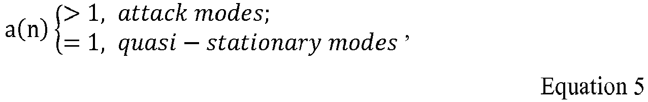
- an attack value a(n) preferably is determined for each sample of the input signal 101, indicating the potential presence of an attack or, more preferably, the strength (e.g., measure of intensity) of any potential attack, as discussed in greater detail below.
- This attack value is coupled to the input of gain-response time (e.g., TC) generation module 152, which preferably then generates attack and release TCs based on it, again as discussed in greater detail below.
- gain-response time e.g., TC
- the attack TC is the main factor in influencing (e.g., primarily controls) how quickly the strength of the output audio signal (e.g., output signal 135) is allowed to increase in response to a sudden increase in strength of the input signal 101 (e.g., how quickly the system will ramp up suppression of the input signal 101 in the apparent presence of an transient attack), while the release TC is the main factor influencing (e.g., primarily controls) how quickly the strength of the output audio signal is allowed to decrease in response to a sudden decrease in strength of the input audio signal(e.g., how quickly the system will return to a quasi-stationary gain after the transient appears to have ended).
- the release TC is the main factor influencing (e.g., primarily controls) how quickly the strength of the output audio signal is allowed to decrease in response to a sudden decrease in strength of the input audio signal(e.g., how quickly the system will return to a quasi-stationary gain after the transient appears to have ended).
- Such TCs are then coupled to, and used by, a filter 153 having another input coupled to the preliminary gain signal 115.
- Filter 153 is a lowpass filter, e.g., implementing a filtering operation such as defined in Equation 3 above, with a variable transfer function that is controlled by the TCs output by gain-response-time generator 152.
- a short attack TC enables rapid gain reduction, thereby preventing powerful attacks from exceeding a specified maximum.
- attacks in audio signals usually do not reach their peak power in the first rising quarter of a sinusoidal cycle in which the amplitude increases, so it will be followed by at least one falling quarter in which the amplitude decreases. Then the magnitude begins to increase again in a subsequent quarter.
- this can be problematic. For instance, with respect to the example given in the Background section above, as can be seen from Equation 3, whenever the magnitude is less than the projected internal state Y 1 ( n ), the releasing mechanism kicks in, which increases the gain.
- the present invention lessens this negating effect by using:
- an approach according to the present invention might reduce the attack TC from 50-100 ms during a quasi-stationary segment to 0-5 or 0-10 ms for a segment during which a transient has been detected.
- an approach according to the present invention might increase the release TC from 50-1,000 ms during a quasi-stationary segment to at least 500 ms, 1 second, 2 seconds, 4 seconds or even infinity (i.e ., by a factor of at least 5, 10, 20, 40 or even infinity) for a segment during which a transient has been detected.
- any function used for this purpose i.e ., an attack function
- c ( n ) is the crest factor (which, e.g., can be directly used as a(n))
- ⁇ c is a pole which can be derived from a TC ⁇ c using Equation 4.
- the ⁇ A (n) and ⁇ R (n) TCs can then be determined.
- release TCs usually are much longer than attack TCs, so the short release TC ⁇ R Short above may be much longer than the long attack TC ⁇ A Long .
- the specific values for the time constants ⁇ A Long , ⁇ A Short , ⁇ R Short and ⁇ R Long preferably are selected from the ranges discussed above for the present invention, but other values may be selected for certain circumstances.
- TCs continuously varying TCs
- ⁇ A max is the maximum (quasi-stationary) attack TC
- ⁇ R min is the minimum (quasi-stationary) release TC
- any other functions that decrease ⁇ A ( n ) and increase ⁇ R ( n ) as a(n) increases instead may be used.
- the specific functions that are used depend upon how a(n) is defined because changes in either such functions or in a(n) can affect how quickly the subject TCs respond to an attack having a particular intensity.
- each will employ attack and release gain-response times (e.g., time constants) in order to generate a time-varying gain signal, which is then applied to the input audio signal (e.g., input signal 101) to provide an output audio signal (e.g., output signal 135).
- gain-response times e.g., time constants
- Such a gain signal often will have different characteristics ( i.e., having been generated differently) in different embodiments (e.g., reflecting either positive or negative gains, defined as linear or logarithmic gains, etc .) and, therefore, the way the gain signal is applied to the input signal typically will vary correspondingly.
- attack function a(n) is based on the power of the input signal, e.g., deciding to enter attack mode based on a determination that the signal's power (or, more generally, strength) is higher than a specified threshold (i.e ., based on a comparison of the strength of the input signal 101 in comparison to a specified threshold), such as the threshold T used in Equation 1.
- a specified threshold i.e ., based on a comparison of the strength of the input signal 101 in comparison to a specified threshold
- T used in Equation 1.
- L ⁇ 1 norm is used in the equation above, in alternate embodiments the L ⁇ 2 norm and/or another norm instead (or also) is used.
- power or “energy” in reference to a signal herein does not imply any specific definition, unless clearly indicated otherwise in the specific context in which such term is used, but instead generally refers to the "strength" of the signal, which may be measured in any of a variety of different ways (e.g., absolute value, square of absolute value, or any of a variety of functions of the foregoing).
- attack function arises from the fact that its value changes with each sample. As a result, the TCs sometimes can change dramatically between samples. While this usually does not cause problems (e.g., due to the presence of level detector 116), a certain degree of smoothing may be applied within the attack function itself.
- a smoothing operation introduces additional delay, which preferably also is accommodated within the delay block 122.
- any other form of negative compression gain instead may be used in any form of DRC.
- One potential problem with the attack functions described above is that the DRC will still be in attack mode even after the peak of an attack has passed, i . e ., after the attack function has reached its maximum and has started to decrease.
- a power detector may be added to modify the attack-function value (e.g., reset it to 1) when the signal power is low.
- a power detector may be added to modify the attack-function value (e.g., reset it to 1) when the signal power is low.
- Equation 12 or Equation 13 is used as the power detector a '( n )
- Frame-based processing is widely used to implement audio processing algorithms.
- algorithmic testing and decision-making can be based on a fixed number of samples within a frame, more robust results often can be obtained.
- n kN + m
- k the frame index
- m the sample index within a frame
- the maximum, mean, median, or other statistic measure of a variable within a frame may be selected as the value to represent the whole frame for that variable.
- these values are then used to decide whether to enter the attack mode or the quasi-stationary mode for the whole frame, thus to determine the respective TCs for all samples in the frame.
- Equation 6 The crest factor given in Equation 6 and the attack function in Equation 13 are well-suited for such a definition.
- Equation 13 is a smoothed version of X L (n) in Equation 12
- Equation 12 or Equation 13 is used as the energy detector (A')
- Equation 13 Because the energy detector in Equation 13 is a smoothed version of that in Equation 12, they can be combined to form the following power-gated crest factor:
- Equation 4 preferably is evaluated for both attack and release poles for each input sample. This amounts to a significant computational burden, especially for low-cost processors such as MCU and DSP. To avoid this problem, in certain embodiments the exponential function in Equation 4 is approximated by its truncated Taylor expansion. For example, the first-order expansion of Equation 4 is given by ⁇ ⁇ 1 ⁇ 1 ⁇ f s
- attack and release poles are calculated only once for all samples in a frame, so the simplification above typically is less valuable.
- Equation 21 When switching from such an attack TC of zero to a non-zero TC, Equation 21 preferably is used to set the internal state Y 1 in Equation 3.
- Equation 21 preferably is used to set the internal state Y 1 in Equation 3.
- Such devices typically will include, for example, at least some of the following components coupled to each other, e.g., via a common bus: (1) one or more central processing units (CPUs); (2) read-only memory (ROM); (3) random access memory (RAM); (4) other integrated or attached storage devices; (5) input/output software and circuitry for interfacing with other devices (e.g., using a hardwired connection, such as a serial port, a parallel port, a USB connection or a FireWire connection, or using a wireless protocol, such as radio-frequency identification (RFID), any other near-field communication (NFC) protocol, Bluetooth or a 802.11 protocol); (6) software and circuitry for connecting to one or more networks, e.g., using a hardwired connection such as an Ethernet
- the process steps to implement the above methods and functionality typically initially are stored in mass storage (e.g., a hard disk or solid-state drive), are downloaded into RAM, and then are executed by the CPU out of RAM.
- mass storage e.g., a hard disk or solid-state drive
- the process steps initially are stored in RAM or ROM and/or are directly executed out of mass storage.
- Suitable general-purpose programmable devices for use in implementing the present invention may be obtained from various vendors.
- different types of devices are used depending upon the size and complexity of the tasks.
- Such devices can include, e.g., mainframe computers, multiprocessor computers, one or more server boxes, workstations, personal (e.g., desktop, laptop, tablet or slate) computers and/or even smaller computers, such as personal digital assistants (PDAs), wireless telephones (e.g., smartphones) or any other programmable appliance or device, whether stand-alone, hard-wired into a network or wirelessly connected to a network.
- PDAs personal digital assistants
- wireless telephones e.g., smartphones
- any other programmable appliance or device whether stand-alone, hard-wired into a network or wirelessly connected to a network.
- any of the functionality described above can be implemented by a general-purpose processor executing software and/or firmware, by dedicated (e.g., logic-based) hardware, or any combination of these approaches, with the particular implementation being selected based on known engineering tradeoffs.
- any process and/or functionality described above is implemented in a fixed, predetermined and/or logical manner, it can be accomplished by a processor executing programming (e.g., software or firmware), an appropriate arrangement of logic components (hardware), or any combination of the two, as will be readily appreciated by those skilled in the art.
- programming e.g., software or firmware
- logic components hardware
- compilers typically are available for both kinds of conversions.
- the present disclosure also relates to machine-readable tangible (or non-transitory) media on which are stored software or firmware program instructions (i.e ., computer-executable process instructions) for performing the methods and functionality and/or for implementing the modules and components of this invention.
- Such media include, by way of example, magnetic disks, magnetic tape, optically readable media such as CDs and DVDs, or semiconductor memory such as various types of memory cards, USB flash memory devices, solid-state drives, etc.
- the medium may take the form of a portable item such as a miniature disk drive or a small disk, diskette, cassette, cartridge, card, stick etc., or it may take the form of a relatively larger or less-mobile item such as a hard disk drive, ROM or RAM provided in a computer or other device.
- references to computer-executable process steps stored on a computer-readable or machine-readable medium are intended to encompass situations in which such process steps are stored on a single medium, as well as situations in which such process steps are stored across multiple media.
- a server generally can (and often will) be implemented using a single device or a cluster of server devices (either local or geographically dispersed), e.g., with appropriate load balancing.
- a server device and a client device often will cooperate in executing the process steps of a complete method, e.g., with each such device having its own storage device(s) storing a portion of such process steps and its own processor(s) executing those process steps.
- Coupled is intended to mean either directly connected or connected through one or more other elements or processing blocks, e.g ., for the purpose of preprocessing.
- elements or processing blocks e.g ., for the purpose of preprocessing.
- couplings which may include additional steps, modules, elements and/or processing blocks.
- Specific processing steps discussedherein are not intended to be exclusive; rather, intermediate processing may be performed between any two processing steps expressly discussed herein.
- gain computer 114 e.g., static gain compression
- level detector 116 e.g., smoothing or lowpass filtering
- any criterion or condition can include any combination (e.g., Boolean combination) of actions, events and/or occurrences ( i.e ., a multi-part criterion or condition).
- functionality sometimes is ascribed to a particular module or component. However, functionality generally may be redistributed as desired among any different modules or components, in some cases completely obviating the need for a particular component or module and/or requiring the addition of new components or modules.
- the precise distribution of functionality preferably is made according to known engineering tradeoffs, with reference to the specific embodiment of the invention, as will be understood by those skilled in the art.
Landscapes
- Engineering & Computer Science (AREA)
- Physics & Mathematics (AREA)
- Multimedia (AREA)
- Health & Medical Sciences (AREA)
- Audiology, Speech & Language Pathology (AREA)
- Human Computer Interaction (AREA)
- Signal Processing (AREA)
- Acoustics & Sound (AREA)
- Computational Linguistics (AREA)
- Quality & Reliability (AREA)
- Spectroscopy & Molecular Physics (AREA)
- Tone Control, Compression And Expansion, Limiting Amplitude (AREA)
- Circuit For Audible Band Transducer (AREA)
Description
- The present invention pertains, among other things, to systems, methods and techniques related to dynamic compression of the range of an audio signal (e.g., from the signal's minimum level to its maximum level) and can be used, e.g., to boost the volume of an audio signal while better preventing or limiting audible distortion and/or damage to output devices such as speakers or headphones, as well as to generally improve a listening experience.
- The dynamic ranges of certain audio passages sometimes are much wider than what the available output device, such as a loudspeaker, can accurately or clearly produce. For example, the reproduced sound might be inaudible when the audio signal is low and clipped or overloaded when the audio signal is high. Someone watching a movie might need to turn down the volume during loud scenes and turn up the volume during quiet scenes.
- Dynamic range compression attempts to address these problems. It refers to a category of technologies for reducing the dynamic range of audio signals to fit playback devices and/or situational requirements. A review of such technologies is given in D. Giannoulis, M. Massberg, and J. Reiss. 2012, "Digital Dynamic Range Compressor Design - A Tutorial and Analysis," Journal of Audio Engineering Society 60: pp. 399-408 (which is referred to herein as "Giannoulis 2012").
- Another overview of related technology can be found in
US 2012/321096 A1 (CROCKETT BRETT GRAHAM [US] ET AL) published 20 December 2012 , in which dynamic gain modifications are applied to an audio signal at least partly in response to auditory events. - One conventional implementation is dynamic range compressor (DRC) 5 shown in
Figure 1 . There,Abs module 10 performs an absolute value operation andLog module 12 performs a logarithmic function. In a more-specific implementation,Log module 12 converts input values into decibels, as follows:
- The
gain computer 14 then implements static range compression, e.g., as follows (from Giannoulis 2012):
gain computer 14 are possible, such as any of those given in Rane Corporation, 2005, "Dynamic Processors - Technology & Application Tips" (which is referred to herein as "Rane 2005"), e.g., including a combination of the foregoing compression with an expander and limiter. - As shown in
Figure 1 , the output of thegain computer 14 is then subtracted from its input, insubtractor 15, to obtain the following negative gain signal:
level detector 16 for essentially applying a smoothing operation to XL so as to obtain a smooth representation of the signal's level. There are many possible implementations oflevel detector 16, including any those described in Giannoulis 2012. In one specific example,level detector 16 performs the following operation: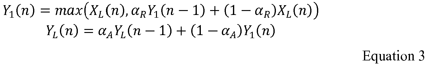


- After smoothing in
level detector 16, in adder 18 a make-up gain 19 (M) is added to the negative of the smoothed negative gain, and the result then is converted by theexponential function module 20 to linear scale, e.g., as follows:
- This linear gain is then applied to the (optionally delayed) input signal, in
multiplier 21, to produce the output signal, as follows:
optional delay unit 22, which may be used to match the delay within the gaincalculation side chain 30 and and/or to provideside chain 30 the ability to "look even further ahead" (e.g., in order to "prime" the DRC 5 to better cope with powerful attacks). However, in someembodiments delay unit 22 is omitted entirely. - As will be readily appreciated from the discussion above, a DRC typically multiplies an input signal with a gain that varies with time, so it performs an operation that introduces distortion into the signal. To keep such distortion low and, ideally, inaudible, large TCs should be used so that the gain changes slowly. Such large TCs work well for quasi-stationary segments of an audio signal, but usually run into problems with transient attacks, or sudden powerful bursts of sounds, such as might be produced by percussive instruments or explosions. When such a powerful attack arrives, the slow gain change produced by large TCs cannot reduce the gain fast enough to prevent the attack from exceeding the upper end of the desired range. As a result, the audio signal might clip in the digital domain (resulting in distortion), the power amplifier might overload (potentially damaging it), and/or the voice coil of the loudspeaker might strike its back plate (potentially damaging the speaker). All of these situations result in annoying sounds and, in some cases, potentially cause damage. It is, therefore, desirable to adapt the TCs to the dynamic varying nature of the input signal, e.g., so as to: (1) allow for fast gain reduction during powerful attacks and (2) provide more slowly varying gains during quasi-stationary segments.
- Some attempts have been made in this regard. For instance, D. Giannoulis, M. Massberg, and J. Reiss, 2013, "Parameter Automation in a Dynamic Range Compressor." Journal of the Audio Engineering Society, 716-726 (which is referred to herein as "Giannoulis 2013") employs a transient or attack detector to differentiate between transient and quasi-stationary segments of the input signal, and then uses shorter TCs for transient segments and longer TCs for quasi-stationary segments. Typically, such conventional approaches use "standard" attack and release TCs during quasi-stationary segments. For example, during quasi-stationary segments, the attack TC might be 50-100 milliseconds (ms), and the release TC (often 10 times as large) might be 500-1,000 ms. Then, when a transient is detected, these values typically are reduced by a factor of 10 or so, i.e., with the attack TC reduced to 5-10 ms and with the release TC reduced to 50-100 ms.
- Unfortunately, while the conventional straightforward approach of using short attack and release TCs during transient attacks and long attack and release TCs during quasi-stationary segments might have seemed intuitively logical, the present inventor has discovered that too often such an approach does not in fact provide good results. The present invention addresses this problem, e.g., by adjusting the TCs, or other measures of how quickly the gain is allowed to change (sometimes referred to herein as the "gain-response times"), differently than has been done in the past.
- It is an object of the invention to create a method and a system for dynamic compression of the range of an audio signal (e.g., from the signal's minimum level to its maximum level) to generally improve a listening experience by better preventing or limiting audible distortion and/or damage to output devices such as speakers or headphones, in response to events such as a boost in volume of an audio signal.
- These and other objects are achieved by the method claimed in claim 1 and the system claimed in claim 11. Advantageous further embodiments are claimed in the dependent claims.
- The foregoing summary is intended merely to provide a brief description of certain aspects of the invention. A more complete understanding of the invention can be obtained by referring to the claims and the following detailed description of the preferred embodiments in connection with the accompanying figures.
- In the following disclosure, the invention is described with reference to the accompanying drawings. However, it should be understood that the drawings merely depict certain representative and/or exemplary embodiments and features of the present invention and are not intended to limit the scope of the invention in any manner. The following is a brief description of each of the accompanying drawings.
-
Figure 1 is a block diagram of a conventional dynamic range compressor (DRC). -
Figure 2 is a block diagram of a DRC according to the present invention. -
Figure 3 is a block diagram of a level detector for use within an embodiment of the present invention. -
Figure 4 is a flow diagram showing an example of the determination of time constants for use in a level detector. - For ease of reference, the present disclosure is divided into sections. The general subject matter of each section is indicated by that section's heading. However, such headings are included simply for the purpose of facilitating readability and are not intended to limit the scope of the invention in any manner whatsoever.
- One example of a
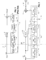
DRC 100 according to the present invention is illustrated inFigure 2 . As shown,DRC 100 inputs asignal 101, designated as x(n). Optionally,input signal 101 is coupled to amodule 110, in which it is pre-processed, e.g., by being subject to a logarithmic function which could be similar or identical to the function implemented by the combination ofconventional modules module 110. For example, in alternate embodiments a logarithmic transformation is not performed, but instead theinput signal 101 is processed in the linear domain, e.g., to reduce computational loads. Input signal 101 (with or without any optional pre-processing 110) is then coupled to gaincomputer 114 which processes its input signal (designated as XG (n)), typically by providing static gain compression to fit its range to a desired output range (e.g., as described above in connection withgain computer 14, such as the specific static gain compression set forth in Equation 1). The output ofgain computer 114 preferably is apreliminary gain signal 115 indicating the instantaneous gain which could be applied at each corresponding point in time (typically, discrete time) to achieve the desired range compression. For example, similar to the conventional implementation discussed above, in certain embodiments gaincomputer 114 also performs an operation that is similar or identical to Equation 2, so that the output of gain computer 114 (preliminary gain signal 115) is a negative gain signal. In other embodiments, thegain computer 114 provides a positive gain signal. In any event,preliminary gain signal 115, which is designated as XL (n), is coupled tolevel detector 116, for smoothing and, in certain embodiments, other adjustments (e.g., as described in greater detail below), resulting in a smoothed gain signal 117, which is designated as YL (n). - Thereafter, any additional adjustments, if desired, are made to the smoothed gain signal 117 (YL (n)) in
optional module 118, e.g., based on one or more input parameters 119 (collectively designated as M). Parameter(s) 119, if provided, may be input manually and/or may be provided by another automated system.Module 118, if used, may implement, e.g., an addition function (typically where logarithmic values are involved) or a multiplication function (typically where linear values are involved). Finally, any desired post-processing, typically the reverse of that applied inmodule 110, is applied inmodule 120 in order to provide a linear gain factor, which is designated as K(n), and which is then used (by multiplier 121) to multiply theinput signal 101, or aftersignal 101 has been optionally delayed within optional delay element 122 (e.g., having the same considerations discussed above in reference to delayelement 22, as well as the additional considerations discussed in this section). That is,multiplier 121 preferably multiplies by theoriginal input signal 101 by a time-varying factor that is reflective of the smoothed gain. Accordingly, its operation can be implemented through direct multiplication ofsuch input signal 101. Alternatively, in alternate embodiments, a logarithmic operation is performed on theinput signal 101, and themultiplier 121 inputs the logarithmic gain and adds it to or subtracts it from (depending upon whether the generated gain signal represents negative or positive gains) the logarithm of theinput signal 101. - In the present embodiment, the
output 135 ofmultiplier 121 is the desired dynamically range-compressed output signal, which is designated as y(n) and typically is coupled, either directly or indirectly (e.g., through additional processing modules, usually including at least digital-to-analog conversion) to an output device 140 (such as a loudspeaker). AlthoughDRC 100 is one example of a DRC according to the present invention, any of a variety of other DRC structures may be used in accordance with the present invention, as will be readily apparent from the discussion below. - One significant aspect of the current embodiment of the present invention is the way in which a
preliminary gain signal 115 is adjusted (e.g., in level detector 116) to better adapt to the instantaneous characteristics of theinput audio signal 101 and thereby achieve a better combination of improved results and reduced distortion. In embodiments where the conventional system 5 (described above) is being modified, such an adjustment preferably is achieved by better controlling the TCs that are used (e.g., within level detector 116) for different portions of the audio signal (115). As also noted elsewhere herein, in alternate embodiments of thelevel detector 116 and gaincomputer 114 are reversed, so that the smoothing is applied to a version of theinput signal 101 prior to determining gains based on it. - In any event, the foregoing aspect of the present invention concerns techniques for better controlling any desired gain-response times (i.e., irrespective of whether or not pertaining to any exponential time constant), with shorter gain-response times meaning that gains are allowed to change more quickly and with longer gain-response times meaning that gains can only change more slowly. The following discussion mainly focuses on improvements to the conventional system described above and, therefore, frequently refers to TCs. It should be understood, however, that any references herein to one or more TCs can be replaced by references to any other gain-response time(s). That is, the approaches discussed herein are not limited to TCs, but instead may be applied in a straightforward manner to the setting of any other gain-response times, however defined.
- Somewhat similar to
level detector 16, discussed above, alevel detector 116 for use in an embodiment according to the present invention preferably is configured as illustrated inFigure 3 . As shown, theinput signal 101 is coupled to anattack detection module 151 oflevel detector 116. Inmodule 151, an attack value a(n) preferably is determined for each sample of theinput signal 101, indicating the potential presence of an attack or, more preferably, the strength (e.g., measure of intensity) of any potential attack, as discussed in greater detail below. This attack value is coupled to the input of gain-response time (e.g., TC)generation module 152, which preferably then generates attack and release TCs based on it, again as discussed in greater detail below. In the preferred embodiments, the attack TC is the main factor in influencing (e.g., primarily controls) how quickly the strength of the output audio signal (e.g., output signal 135) is allowed to increase in response to a sudden increase in strength of the input signal 101 (e.g., how quickly the system will ramp up suppression of theinput signal 101 in the apparent presence of an transient attack), while the release TC is the main factor influencing (e.g., primarily controls) how quickly the strength of the output audio signal is allowed to decrease in response to a sudden decrease in strength of the input audio signal(e.g., how quickly the system will return to a quasi-stationary gain after the transient appears to have ended). - Such TCs are then coupled to, and used by, a
filter 153 having another input coupled to thepreliminary gain signal 115.Filter 153 is a lowpass filter, e.g., implementing a filtering operation such as defined in Equation 3 above, with a variable transfer function that is controlled by the TCs output by gain-response-time generator 152. Thus, other (more-specific) significant aspects of the present invention are: (1) the manner in which the TCs are generated and (2) because such TCs are based on them, how the attack values are determined. Therefore, a significant portion of the following discussion focuses on these two features. - With regard to the filtering operation performed by
filter 153, a short attack TC enables rapid gain reduction, thereby preventing powerful attacks from exceeding a specified maximum. However, attacks in audio signals usually do not reach their peak power in the first rising quarter of a sinusoidal cycle in which the amplitude increases, so it will be followed by at least one falling quarter in which the amplitude decreases. Then the magnitude begins to increase again in a subsequent quarter. Using conventional approaches, this can be problematic. For instance, with respect to the example given in the Background section above, as can be seen from Equation 3, whenever the magnitude is less than the projected internal state Y 1(n), the releasing mechanism kicks in, which increases the gain. As a result, the gain reduction desired for coping with the powerful attack that will arrive in subsequent quarter(s) will have already been negated. The shorter the release TC, the greater this negating effect is. In one aspect, therefore, the present invention lessens this negating effect by using: - Longer release TCs during transient attacks; and
- Shorter or normal release TCs during quasi-stationary segments.
- During periods of time when a transient attack has been determined to be occurring (in
step 181, e.g., based on anattack value 160 provided by detector 151), the DRC enters attack mode (step 182) in which (relative to the quasi-stationary segments) shorter attack and longer release TCs are used. - During other times (quasi-stationary segments, as determined in
step 181, e.g., based on anattack value 160 provided by detector 151), the DRC enters quasi-stationary mode (step 183) in which (relative to the transient segments) longer attack and shorter or normal release TCs are used. - That is, unlike conventional approaches in which both attack and release TCs move in the same direction (shorter during attacks and longer during quasi-stationary segments), in the preferred embodiments of the present invention, they move in opposite directions (with attack TCs being shorter when a transient has been detected and longer during quasi-stationary segments, but with release TCs being longer when a transient has been detected and shorter during quasi-stationary segments). Thus, somewhat similar to the conventional techniques described in the Background section above, an approach according to the present invention might reduce the attack TC from 50-100 ms during a quasi-stationary segment to 0-5 or 0-10 ms for a segment during which a transient has been detected. However, in stark contrast to the conventional techniques, an approach according to the present invention might increase the release TC from 50-1,000 ms during a quasi-stationary segment to at least 500 ms, 1 second, 2 seconds, 4 seconds or even infinity (i.e., by a factor of at least 5, 10, 20, 40 or even infinity) for a segment during which a transient has been detected.
- For this purpose, it initially is desirable to determine when a transient is occurring. The present embodiment contemplates several different embodiments in this regard. However, it generally is preferred that any function used for this purpose (i.e., an attack function) satisfies the following requirement:
- One example of such an attack function is based on the crest factor detector presented in Giannoulis 2013, but replacing its use of RMS values with peak values, so as to arrive at the following crest factor detector:

- In any event, once a value has been determined for the attack function a(n), the τ A (n) and τ R (n) TCs can then be determined. One approach to doing so is as follows:


- Alternatively, if continuously varying TCs are desired, they can be determined using a soft decision-making mechanism, such as the following:


- The foregoing discussion mainly concerns a particular embodiment of the present invention. However, as discussed throughout this disclosure, many different embodiments are possible. Each will employ attack and release gain-response times (e.g., time constants) in order to generate a time-varying gain signal, which is then applied to the input audio signal (e.g., input signal 101) to provide an output audio signal (e.g., output signal 135). Such a gain signal often will have different characteristics (i.e., having been generated differently) in different embodiments (e.g., reflecting either positive or negative gains, defined as linear or logarithmic gains, etc.) and, therefore, the way the gain signal is applied to the input signal typically will vary correspondingly.
- The following sections discuss various alternative embodiments, e.g., employing different attack functions.
- Another type of attack function a(n) that can be used in the present invention is based on the power of the input signal, e.g., deciding to enter attack mode based on a determination that the signal's power (or, more generally, strength) is higher than a specified threshold (i.e., based on a comparison of the strength of the
input signal 101 in comparison to a specified threshold), such as the threshold T used in Equation 1. The simplest power detector looks at the absolute value of the input signal. For example, in order to comply with Equation 5, such an attack function may be defined as: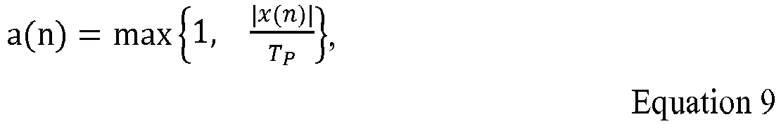
- One potential issue with the foregoing attack function arises from the fact that its value changes with each sample. As a result, the TCs sometimes can change dramatically between samples. While this usually does not cause problems (e.g., due to the presence of level detector 116), a certain degree of smoothing may be applied within the attack function itself. For example, the usual one-pole filter can be used for this purpose:

delay block 122. - If the crest factor in Equation 6 is used and the absolute value of the input sample is used as the power detector,
Equation 10 becomes the same as the second equation of Equation 6. Therefore, YAbs(n) may be used directly to construct the attack function, e.g., as follows:
- Because the negative gain XL(n) defined in Equation 2 is always greater than or equal to zero dB and its calculation involves a thresholding mechanism, it can be used directly as an attack function, i.e.:

- The smoothed version of it, YL(n), is suitable for situations where smoothing is desired, i.e.:

- It is noted that, while XL(n) and YL(n) are used above, any other form of negative compression gain instead may be used in any form of DRC.
- One potential problem with the attack functions described above is that the DRC will still be in attack mode even after the peak of an attack has passed, i.e., after the attack function has reached its maximum and has started to decrease. This problem can be remedied by using an incremental attack function such as the following:

- As may be seen from Equation 6, the crest factor is not dependent on the power of the input signal. Therefore, using it directly as the attack function will cause the DRC to enter attack mode even in situations where the signal power is too low for the DRC to incur compression. In order to prevent this from happening, a power detector may be added to modify the attack-function value (e.g., reset it to 1) when the signal power is low. One specific example (which also uses an incremental crest factor) is as follows:

- Alternatively, rather than using an incremental crest factor as above, an incremental power threshold may be used to ensure that the DRC enters attack mode only on the rising edge of an attack, e.g.:

Equation 12 or Equation 13 is used as the power detector a'(n), the power thresholding (a'(n) > TP ) is performed in Equation 1, and therefore can be dropped in the equation above to give
- Frame-based processing is widely used to implement audio processing algorithms. When algorithmic testing and decision-making can be based on a fixed number of samples within a frame, more robust results often can be obtained.
- Let N denote the number of samples in a frame, the sample index n may be represented as


- The maximum, mean, median, or other statistic measure of a variable within a frame may be selected as the value to represent the whole frame for that variable. Using the maximum as an example, the attack function and crest factor values for the k-th frame may be defined as


- In certain embodiments, these values are then used to decide whether to enter the attack mode or the quasi-stationary mode for the whole frame, thus to determine the respective TCs for all samples in the frame.
- For example, the incremental attack function of
Equation 14 may be modified for the k-th frame in a frame-based system as follows:
- If a smoothing operation is involved with the calculation of attack function values of ak(n), Ak-1 may be replaced by the last sample of the attack function in the previous frame, as follows:

- The crest factor given in Equation 6 and the attack function in Equation 13 are well-suited for such a definition.
- Because YL(n) in Equation 13 is a smoothed version of XL(n) in
Equation 12, the Ak inEquation 18 may be replaced by the maximum of XL(n) in the frame so that
- The power-gated incremental crest factor defined in
Equation 15 may be modified for a frame as
Equation 16 may also be modified for a frame as
- If
Equation 12 or Equation 13 is used as the energy detector (A'), the power thresholding (A'k > TP ) is performed in Equation 1, so the above equation may be simplified as:
- Because the energy detector in Equation 13 is a smoothed version of that in
Equation 12, they can be combined to form the following power-gated crest factor:
- The attack functions obtained above may be used to make the decision as to whether or not the DRC enters attack or quasi-stationary mode for the whole frame, thus to determine respective TCs for all samples in the frame. For example, Equation 7 may be modified for frame-based processing as:


- Because the TCs change with each input sample, the exponential function of Equation 4 preferably is evaluated for both attack and release poles for each input sample. This amounts to a significant computational burden, especially for low-cost processors such as MCU and DSP. To avoid this problem, in certain embodiments the exponential function in Equation 4 is approximated by its truncated Taylor expansion. For example, the first-order expansion of Equation 4 is given by

- Plugging this equation into Equation 8, we have


- For frame-based processing, attack and release poles are calculated only once for all samples in a frame, so the simplification above typically is less valuable.
- The one-pole IIR filters in Equation 3 may also be simplified for the extreme case(s) of


- If
Equation 19 is used, the second part of Equation 3 reduces to

- When switching from such an attack TC of zero to a non-zero TC,
Equation 21 preferably is used to set the internal state Y 1 in Equation 3. - Similarly, if
Equation 20 is used, the first part of Equation 3 is simplified to
Equation 19 andEquation 20 are used, the whole Equation 3 may be simplified to
- Again, when switching from such an attack TC of zero to a non-zero TC,
Equation 21 preferably is used to set the internal state Y 1 in Equation 3. - Generally speaking, except where clearly indicated otherwise, all of the systems, methods, modules, components, functionality and techniques described herein can be practiced with the use of one or more programmable general-purpose computing devices. Such devices (e.g., including any of the electronic devices mentioned herein) typically will include, for example, at least some of the following components coupled to each other, e.g., via a common bus: (1) one or more central processing units (CPUs); (2) read-only memory (ROM); (3) random access memory (RAM); (4) other integrated or attached storage devices; (5) input/output software and circuitry for interfacing with other devices (e.g., using a hardwired connection, such as a serial port, a parallel port, a USB connection or a FireWire connection, or using a wireless protocol, such as radio-frequency identification (RFID), any other near-field communication (NFC) protocol, Bluetooth or a 802.11 protocol); (6) software and circuitry for connecting to one or more networks, e.g., using a hardwired connection such as an Ethernet card or a wireless protocol, such as code division multiple access (CDMA), global system for mobile communications (GSM), Bluetooth, a 802.11 protocol, or any other cellular-based or non-cellular-based system, which networks, in turn, in many embodiments of the invention, connect to the Internet or to any other networks; (7) a display (such as a cathode ray tube display, a liquid crystal display, an organic light-emitting display, a polymeric light-emitting display or any other thin-film display); (8) other output devices (such as one or more speakers, a headphone set, a laser or other light projector and/or a printer); (9) one or more input devices (such as a mouse, one or more physical switches or variable controls, a touchpad, tablet, touch-sensitive display or other pointing device, a keyboard, a keypad, a microphone and/or a camera or scanner); (10) a mass storage unit (such as a hard disk drive or a solid-state drive); (11) a real-time clock; (12) a removable storage read/write device (such as a flash drive, any other portable drive that utilizes semiconductor memory, a magnetic disk, a magnetic tape, an opto-magnetic disk, an optical disk, or the like); and/or (13) a modem (e.g., for sending faxes or for connecting to the Internet or to any other computer network). In operation, the process steps to implement the above methods and functionality, to the extent performed by such a general-purpose computer, typically initially are stored in mass storage (e.g., a hard disk or solid-state drive), are downloaded into RAM, and then are executed by the CPU out of RAM. However, in some cases the process steps initially are stored in RAM or ROM and/or are directly executed out of mass storage.
- Suitable general-purpose programmable devices for use in implementing the present invention may be obtained from various vendors. In the various embodiments, different types of devices are used depending upon the size and complexity of the tasks. Such devices can include, e.g., mainframe computers, multiprocessor computers, one or more server boxes, workstations, personal (e.g., desktop, laptop, tablet or slate) computers and/or even smaller computers, such as personal digital assistants (PDAs), wireless telephones (e.g., smartphones) or any other programmable appliance or device, whether stand-alone, hard-wired into a network or wirelessly connected to a network.
- In addition, although general-purpose programmable devices have been described above, in alternate embodiments one or more special-purpose processors or computers instead (or in addition) are used. In general, it should be noted that, except as expressly noted otherwise, any of the functionality described above can be implemented by a general-purpose processor executing software and/or firmware, by dedicated (e.g., logic-based) hardware, or any combination of these approaches, with the particular implementation being selected based on known engineering tradeoffs. More specifically, where any process and/or functionality described above is implemented in a fixed, predetermined and/or logical manner, it can be accomplished by a processor executing programming (e.g., software or firmware), an appropriate arrangement of logic components (hardware), or any combination of the two, as will be readily appreciated by those skilled in the art. In other words, it is well-understood how to convert logical and/or arithmetic operations into instructions for performing such operations within a processor and/or into logic gate configurations for performing such operations; in fact, compilers typically are available for both kinds of conversions.
- It should be understood that the present disclosure also relates to machine-readable tangible (or non-transitory) media on which are stored software or firmware program instructions (i.e., computer-executable process instructions) for performing the methods and functionality and/or for implementing the modules and components of this invention. Such media include, by way of example, magnetic disks, magnetic tape, optically readable media such as CDs and DVDs, or semiconductor memory such as various types of memory cards, USB flash memory devices, solid-state drives, etc. In each case, the medium may take the form of a portable item such as a miniature disk drive or a small disk, diskette, cassette, cartridge, card, stick etc., or it may take the form of a relatively larger or less-mobile item such as a hard disk drive, ROM or RAM provided in a computer or other device. As used herein, unless clearly noted otherwise, references to computer-executable process steps stored on a computer-readable or machine-readable medium are intended to encompass situations in which such process steps are stored on a single medium, as well as situations in which such process steps are stored across multiple media.
- The foregoing description primarily emphasizes electronic computers and devices. However, it should be understood that any other computing or other type of device instead may be used, such as a device utilizing any combination of electronic, optical, biological and chemical processing that is capable of performing basic logical and/or arithmetic operations.
- In addition, where the present disclosure refers to a processor, computer, server, server device, computer-readable medium or other storage device, client device, or any other kind of apparatus or device, such references should be understood as encompassing the use of plural such processors, computers, servers, server devices, computer-readable media or other storage devices, client devices, or any other such apparatuses or devices, except to the extent clearly indicated otherwise. For instance, a server generally can (and often will) be implemented using a single device or a cluster of server devices (either local or geographically dispersed), e.g., with appropriate load balancing. Similarly, a server device and a client device often will cooperate in executing the process steps of a complete method, e.g., with each such device having its own storage device(s) storing a portion of such process steps and its own processor(s) executing those process steps.
- As used herein, the term "coupled", or any other form of the word, is intended to mean either directly connected or connected through one or more other elements or processing blocks, e.g., for the purpose of preprocessing. In the drawings and/or the discussions of them, where individual steps, modules or processing blocks are shown and/or discussed as being directly connected to each other, such connections should be understood as couplings, which may include additional steps, modules, elements and/or processing blocks. Specific processing steps discussedherein are not intended to be exclusive; rather, intermediate processing may be performed between any two processing steps expressly discussed herein.
- In the preceding discussion, the terms "operators", "operations", "functions" and similar terms refer to process steps or hardware components, depending upon the particular implementation/embodiment.
- Unless clearly indicated to the contrary, words such as "optimal", "optimize", "maximize", "minimize", "best", as well as similar words and other words and suffixes denoting comparison, in the above discussion are not used in their absolute sense. Instead, such terms ordinarily are intended to be understood in light of any other potential constraints, such as user-specified constraints and objectives, as well as cost and processing or manufacturing constraints.
- In the above discussion, certain methods are explained by breaking them down into steps listed in a particular order. Similarly, certain processing is performed by showing and describing modules arranged in a certain order. However, it should be noted that in each such case, except to the extent clearly indicated to the contrary or mandated by practical considerations (such as where the results from one step are necessary to perform another), the indicated order is not critical but, instead, that the described steps and/or modules can be reordered and/or two or more of such steps (or the processing within two or more of such modules) can be performed concurrently. For instance, in system 100 (shown in
Figure 2 ) again computer 114 precedes thelevel detector 116. However, in alternate embodiments thelevel detector 116 precedes thegain computer 114. More generally, one can define a larger adaptive gain-generation module 132 that includes the functionality of gain computer 114 (e.g., static gain compression) and level detector 116 (e.g., smoothing or lowpass filtering), potentially together with additional functionality (whether or not shown inFigure 2 ), with such functionality arranged in a variety of different ways, as will be readily understood by those of ordinary skill in the art. For instance, as is well-known, operations that are linear and time-invariant typically can be arranged in any desired order. - References herein to a "criterion", "multiple criteria", "condition", "conditions" or similar words which are intended to trigger, limit, filter or otherwise affect processing steps, other actions, the subjects of processing steps or actions, or any other activity or data, are intended to mean "one or more", irrespective of whether the singular or the plural form has been used. For instance, any criterion or condition can include any combination (e.g., Boolean combination) of actions, events and/or occurrences (i.e., a multi-part criterion or condition).
- Similarly, in the discussion above, functionality sometimes is ascribed to a particular module or component. However, functionality generally may be redistributed as desired among any different modules or components, in some cases completely obviating the need for a particular component or module and/or requiring the addition of new components or modules. The precise distribution of functionality preferably is made according to known engineering tradeoffs, with reference to the specific embodiment of the invention, as will be understood by those skilled in the art.
- Several different embodiments of the present invention are described above with each such embodiment described as including certain features. However, it is intended that the features described in connection with the discussion of any single embodiment are not limited to that embodiment but may be included and/or arranged in various combinations in any of the other embodiments as well, as will be understood by those skilled in the art.
- Thus, although the present invention has been described in detail with regard to the exemplary embodiments thereof and accompanying drawings, it should be apparent to those skilled in the art that various adaptations and modifications of the present invention may be accomplished without departing from the scope of the invention. Accordingly, the invention is not limited to the precise embodiments shown in the drawings and described above. Rather, it is intended that all such variations are to be considered as within the scope thereof as limited solely by the claims appended hereto.
Claims (16)
- A method of compressing the dynamic range of an audio signal, comprising:(a) obtaining an input audio signal (101);(b) providing a time-varying gain signal (117) based on the input audio signal (101) and a desired output range; and(c) applying the time-varying gain signal (117) to the input audio signal (101) to provide an output audio signal (135),wherein said step (b) includes: i) determining and providing an indication of whether a transient is occurring in the input audio signal (101), ii) providing an attack gain-response time and a release gain-response time based on the indication of whether a transient is occurring in the input audio signal (101), andiii) lowpass filtering a signal that is based on the input audio signal (101), using the attack gain-response time and the release gain-response time as filtering parameters,
characterized in thatthe attack gain-response time is decreased and the release gain-response time is increased in response to a determination that a transient is occurring in the input audio signal (101). - A method according to claim 1, wherein the indication of whether a transient is occurring in the input audio signal (101) indicates a measure of intensity of a detected transient.
- A method according to claim 2, wherein the attack gain-response time decreases more and the release gain-response time increases more as a result of a larger measure of intensity of a detected transient.
- A method according to any of the preceding claims, wherein the indication of whether a transient is occurring in the input audio signal (101) is based on a crest factor detector that uses peak values.
- A method according to any of the preceding claims, wherein the indication of whether a transient is occurring in the input audio signal (101) is based on a strength of the input audio signal (101) in comparison to a specified threshold.
- A method according to any of the preceding claims, wherein the indication of whether a transient is occurring in the input audio signal (101) is calculated as an incremental value, by first determining preliminary attack values and then calculating the incremental value as an amount of change between a previous one of the preliminary attack values and a current one of the preliminary attack values.
- A method according to any of the preceding claims, wherein the input audio signal (101) is frame-based and the indication of whether a transient is occurring in the input audio signal (101) is determined for individual frames of the input audio signal (101).
- A method according to any of the preceding claims, wherein said step (b) also includes identifying gains to achieve a desired static range compression.
- A method according to any of the preceding claims, wherein each of the attack gain-response time and the release gain-response time is an exponential time constant.
- A method according to any of the preceding claims, wherein the attack gain-response time primarily controls how fast strength of the output audio signal (135) is allowed to increase in response to a sudden increase in strength of the input audio signal (101), and the release gain-response time primarily controls how fast strength of the output audio signal (135) is allowed to decrease in response to a sudden decrease in strength of the input audio signal (101).
- A system for compressing the dynamic range of an audio signal, comprising:(a) a system input configured to accept an input audio signal (101);(b) an adaptive gain-generation module (132) having an input coupled to the system input and an output, the adaptive gain-generation module (132) being configured to provide at the output a time-varying gain signal (117) based on the input audio signal (101) and a desired output range;(c) a multiplier (121) having a first input coupled to the system input, a second input coupled to the output of the adaptive gain-generation module (132), and an output, wherein the adaptive gain-generation module (132) includes a gain computer (114) and a level detector (116) having an input and an output,wherein the level detector (116) includes: (i) an attack-detection module (151) configured to determine and provide an indication of whether a transient is occurring in the input audio signal (101), (ii) a gain-response-time generator (152) configured to provide an attack gain-response time and a release gain-response time based on the indication of whether a transient is occurring in the input audio signal (101) that has been provided by the attack-detection module (151), and (iii) a filter (153) configured to lowpass filter a signal that has been input into the level detector (116), using the attack gain-response time and the release gain-response time as filtering parameters,
characterized in that
the gain-response-time generator (152) is configured to shorten the attack gain-response time and to increase the release gain-response time in response to a transient detection by the attack-detection module (151). - A system according to claim 11, wherein the indication of whether a transient is occurring in the input audio signal (101) provided by the attack-detection module (151) indicates a measure of intensity of a detected transient, and wherein the attack gain-response time decreases more and the release gain-response time increases more as a result of a larger measure of intensity of a detected transient.
- A system according to claim 11 or 12, wherein the indication of whether a transient is occurring in the input audio signal (101) is based on a crest factor detector that uses peak values.
- A system according to any of claims 11 - 13, wherein the indication of whether a transient is occurring in the input audio signal (101) is based on a strength of the input audio signal (101) in comparison to a specified threshold.
- A system according to any of claims 11 - 14, wherein the indication of whether a transient is occurring in the input audio signal (101) is calculated as an incremental value, by first determining preliminary attack values and then calculating the incremental value as an amount of change between a previous one of the preliminary attack values and a current one of the preliminary attack values.
- A system according to any of claims 11 - 15, wherein the attack gain-response time primarily controls how fast strength of the output audio signal (135) is allowed to increase in response to a sudden increase in strength of the input audio signal (101), and the release gain-response time primarily controls how fast strength of the output audio signal (135) is allowed to decrease in response to a sudden decrease in strength of the input audio signal (101).
Applications Claiming Priority (1)
| Application Number | Priority Date | Filing Date | Title |
|---|---|---|---|
| US16/022,819 US11011180B2 (en) | 2018-06-29 | 2018-06-29 | Audio signal dynamic range compression |
Publications (2)
| Publication Number | Publication Date |
|---|---|
| EP3588776A1 EP3588776A1 (en) | 2020-01-01 |
| EP3588776B1 true EP3588776B1 (en) | 2022-07-20 |
Family
ID=64316343
Family Applications (1)
| Application Number | Title | Priority Date | Filing Date |
|---|---|---|---|
| EP18206155.6A Revoked EP3588776B1 (en) | 2018-06-29 | 2018-11-14 | Audio signal dynamic range compression |
Country Status (4)
| Country | Link |
|---|---|
| US (1) | US11011180B2 (en) |
| EP (1) | EP3588776B1 (en) |
| JP (1) | JP6846397B2 (en) |
| CN (1) | CN110728985B (en) |
Families Citing this family (7)
| Publication number | Priority date | Publication date | Assignee | Title |
|---|---|---|---|---|
| US11444590B2 (en) * | 2019-12-16 | 2022-09-13 | Synaptics Incorporated | Class-G control system with low latency signal path |
| WO2021233809A1 (en) * | 2020-05-20 | 2021-11-25 | Dolby International Ab | Method and unit for performing dynamic range control |
| CN114125658B (en) * | 2020-08-25 | 2023-12-19 | 上海艾为电子技术股份有限公司 | Dynamic range control circuit, audio processing chip and audio processing method thereof |
| CN114095832B (en) * | 2020-08-25 | 2024-06-25 | 上海艾为电子技术股份有限公司 | Multi-section dynamic range control circuit, audio processing chip and audio processing method |
| CZ309327B6 (en) * | 2021-04-15 | 2022-08-24 | KV2 Audio International spol. s.r.o. | Audio dynamic range compressor |
| CN115079990A (en) * | 2022-05-06 | 2022-09-20 | 珠海全志科技股份有限公司 | Method, device, server, client and storage medium for adjusting audio range |
| CN115019813B (en) * | 2022-05-31 | 2025-06-17 | 漳州立达信光电子科技有限公司 | A sound energy detection method, device and medium |
Citations (10)
| Publication number | Priority date | Publication date | Assignee | Title |
|---|---|---|---|---|
| JPH06164275A (en) | 1992-11-27 | 1994-06-10 | Sanyo Electric Co Ltd | Signal processor |
| US5553151A (en) | 1992-09-11 | 1996-09-03 | Goldberg; Hyman | Electroacoustic speech intelligibility enhancement method and apparatus |
| US5832444A (en) | 1996-09-10 | 1998-11-03 | Schmidt; Jon C. | Apparatus for dynamic range compression of an audio signal |
| EP0961120A2 (en) | 1998-05-08 | 1999-12-01 | Tektronix, Inc. | Smart auto-ranging rms measurement method and apparatus |
| US20020051546A1 (en) | 1999-11-29 | 2002-05-02 | Bizjak Karl M. | Variable attack & release system and method |
| US20060233408A1 (en) | 2005-03-29 | 2006-10-19 | Kates James M | Hearing aid with adaptive compressor time constants |
| EP1923994A1 (en) | 2006-11-17 | 2008-05-21 | AKG Acoustics GmbH | Audio compressor |
| EP2009786A1 (en) | 2007-06-25 | 2008-12-31 | Harman Becker Automotive Systems GmbH | Feedback limiter with adaptive control of time constants |
| US20120025908A1 (en) | 2010-07-29 | 2012-02-02 | Nxp B.V. | Automatic gain control |
| US20120321096A1 (en) | 2006-04-27 | 2012-12-20 | Dolby Laboratories Licensing Corporation | Audio Gain Control Using Specific-Loudness-Based Auditory Event Detection |
Family Cites Families (12)
| Publication number | Priority date | Publication date | Assignee | Title |
|---|---|---|---|---|
| GB2179809B (en) * | 1983-09-21 | 1987-10-21 | British Broadcasting Corp | Dynamic range control of a signal |
| US6757396B1 (en) | 1998-11-16 | 2004-06-29 | Texas Instruments Incorporated | Digital audio dynamic range compressor and method |
| JP3497813B2 (en) * | 1999-09-27 | 2004-02-16 | テキサス インスツルメンツ インコーポレイテツド | Digital audio dynamic range compressor |
| WO2006047600A1 (en) * | 2004-10-26 | 2006-05-04 | Dolby Laboratories Licensing Corporation | Calculating and adjusting the perceived loudness and/or the perceived spectral balance of an audio signal |
| CN101964190B (en) * | 2009-07-24 | 2014-05-21 | 敦泰科技(深圳)有限公司 | Method and device for restoring signal under speaker cut-off frequency to original sound |
| US9685921B2 (en) * | 2012-07-12 | 2017-06-20 | Dts, Inc. | Loudness control with noise detection and loudness drop detection |
| US9559651B2 (en) * | 2013-03-29 | 2017-01-31 | Apple Inc. | Metadata for loudness and dynamic range control |
| WO2015111084A2 (en) * | 2014-01-27 | 2015-07-30 | Indian Institute Of Technology Bombay | Dynamic range compression with low distortion for use in hearing aids and audio systems |
| ES2627227T3 (en) * | 2014-01-30 | 2017-07-27 | Huawei Technologies Co., Ltd. | A digital compressor to compress an audio signal |
| GB201406574D0 (en) * | 2014-04-11 | 2014-05-28 | Microsoft Corp | Audio Signal Processing |
| GB2527126B (en) * | 2014-06-13 | 2019-02-06 | Elaratek Ltd | Noise cancellation with dynamic range compression |
| CN106504766B (en) * | 2016-11-28 | 2019-11-26 | 湖南国科微电子股份有限公司 | A kind of dynamic range compression method of digital audio and video signals |
-
2018
- 2018-06-29 US US16/022,819 patent/US11011180B2/en active Active
- 2018-11-08 JP JP2018210888A patent/JP6846397B2/en active Active
- 2018-11-14 EP EP18206155.6A patent/EP3588776B1/en not_active Revoked
- 2018-11-29 CN CN201811443857.5A patent/CN110728985B/en active Active
Patent Citations (10)
| Publication number | Priority date | Publication date | Assignee | Title |
|---|---|---|---|---|
| US5553151A (en) | 1992-09-11 | 1996-09-03 | Goldberg; Hyman | Electroacoustic speech intelligibility enhancement method and apparatus |
| JPH06164275A (en) | 1992-11-27 | 1994-06-10 | Sanyo Electric Co Ltd | Signal processor |
| US5832444A (en) | 1996-09-10 | 1998-11-03 | Schmidt; Jon C. | Apparatus for dynamic range compression of an audio signal |
| EP0961120A2 (en) | 1998-05-08 | 1999-12-01 | Tektronix, Inc. | Smart auto-ranging rms measurement method and apparatus |
| US20020051546A1 (en) | 1999-11-29 | 2002-05-02 | Bizjak Karl M. | Variable attack & release system and method |
| US20060233408A1 (en) | 2005-03-29 | 2006-10-19 | Kates James M | Hearing aid with adaptive compressor time constants |
| US20120321096A1 (en) | 2006-04-27 | 2012-12-20 | Dolby Laboratories Licensing Corporation | Audio Gain Control Using Specific-Loudness-Based Auditory Event Detection |
| EP1923994A1 (en) | 2006-11-17 | 2008-05-21 | AKG Acoustics GmbH | Audio compressor |
| EP2009786A1 (en) | 2007-06-25 | 2008-12-31 | Harman Becker Automotive Systems GmbH | Feedback limiter with adaptive control of time constants |
| US20120025908A1 (en) | 2010-07-29 | 2012-02-02 | Nxp B.V. | Automatic gain control |
Non-Patent Citations (7)
| Title |
|---|
| ANONYMOUS: "Dynamic range compression - Wikipedia, the free encyclopedia", 7 July 2003 (2003-07-07), XP055257152, Retrieved from the Internet <URL:https://en.wikipedia.org/wiki/Dynamic_range_compression> [retrieved on 20160310] |
| ANONYMOUS: "Model LA-2A Leveling Amplifier", UNIVERSAL STUDIOS, 1 January 2000 (2000-01-01), pages 1 - 21, XP093045692, Retrieved from the Internet <URL:https://media.uaudio.com/assetlibrary/l/a/la-2a_manual.pdf> [retrieved on 20230510] |
| BALAJI THOSHKAHNA, NSABIMANA F X, RAMAKRISHNAN K R: "A TRANSIENT DETECTION ALGORITHM FOR AUDIO USING ITERATIVE ANALYSIS OF STFT", 12TH INTERNATIONAL SOCIETY FOR MUSIC INFORMATION RETRIEVAL CONFERENCE, 1 January 2011 (2011-01-01), XP055089943, Retrieved from the Internet <URL:http://ismir2011.ismir.net/papers/PS2-6.pdf> [retrieved on 20131125] |
| G. DIMITRIOS ET AL.: "Digital Dynamic Range Compressor Design - A Tutorial and Analysis", J. AUDIO ENG. SOC., vol. 60, 6 June 2012 (2012-06-06), XP040574680 |
| G. DIMITRIOS ET AL.: "Parameter Automation in a Dynamic Range Compressor", J. AUDIO ENG. SOC., vol. 61, no. 10, October 2013 (2013-10-01), XP040633191 |
| G. MCNALLY: "Dynamic Range Control of Digital Audio Signals", J. AUDIO ENG. SOC., vol. 32, May 1984 (1984-05-01), pages 316 - 327, XP055348614 |
| M. SENIOR: "Mixing Secrets for the Small Studio", MIXING SECRETS FOR THE SMALL STUDIO, 2011, pages 1 - 463 |
Also Published As
| Publication number | Publication date |
|---|---|
| US11011180B2 (en) | 2021-05-18 |
| US20200005802A1 (en) | 2020-01-02 |
| EP3588776A1 (en) | 2020-01-01 |
| CN110728985A (en) | 2020-01-24 |
| JP2020005239A (en) | 2020-01-09 |
| JP6846397B2 (en) | 2021-03-24 |
| CN110728985B (en) | 2022-07-19 |
Similar Documents
| Publication | Publication Date | Title |
|---|---|---|
| EP3588776B1 (en) | Audio signal dynamic range compression | |
| EP3148075B1 (en) | Loudness-based audio-signal compensation | |
| US9794688B2 (en) | Addition of virtual bass in the frequency domain | |
| US10405094B2 (en) | Addition of virtual bass | |
| US9794689B2 (en) | Addition of virtual bass in the time domain | |
| CN102549659A (en) | Suppressing noise in an audio signal | |
| CN101388652A (en) | Feedback limiter with adaptive control of time constants | |
| US11817115B2 (en) | Enhanced de-esser for in-car communication systems | |
| US20230353101A1 (en) | Power Limiter Configuration for Audio Signals | |
| EP3618274B1 (en) | Multiband audio signal dynamic range compression with overshoot suppression | |
| Corey et al. | Modeling the effects of dynamic range compression on signals in noise | |
| US10893362B2 (en) | Addition of virtual bass | |
| GB2454470A (en) | Controlling an audio signal by analysing samples between zero crossings of the signal | |
| WO2023098103A1 (en) | Audio processing method and audio processing apparatus | |
| CN105323695A (en) | Adaptive detector and auto mode for dynamics processor |
Legal Events
| Date | Code | Title | Description |
|---|---|---|---|
| PUAI | Public reference made under article 153(3) epc to a published international application that has entered the european phase |
Free format text: ORIGINAL CODE: 0009012 |
|
| STAA | Information on the status of an ep patent application or granted ep patent |
Free format text: STATUS: THE APPLICATION HAS BEEN PUBLISHED |
|
| AK | Designated contracting states |
Kind code of ref document: A1 Designated state(s): AL AT BE BG CH CY CZ DE DK EE ES FI FR GB GR HR HU IE IS IT LI LT LU LV MC MK MT NL NO PL PT RO RS SE SI SK SM TR |
|
| AX | Request for extension of the european patent |
Extension state: BA ME |
|
| STAA | Information on the status of an ep patent application or granted ep patent |
Free format text: STATUS: REQUEST FOR EXAMINATION WAS MADE |
|
| 17P | Request for examination filed |
Effective date: 20200619 |
|
| RBV | Designated contracting states (corrected) |
Designated state(s): AL AT BE BG CH CY CZ DE DK EE ES FI FR GB GR HR HU IE IS IT LI LT LU LV MC MK MT NL NO PL PT RO RS SE SI SK SM TR |
|
| GRAP | Despatch of communication of intention to grant a patent |
Free format text: ORIGINAL CODE: EPIDOSNIGR1 |
|
| STAA | Information on the status of an ep patent application or granted ep patent |
Free format text: STATUS: GRANT OF PATENT IS INTENDED |
|
| INTG | Intention to grant announced |
Effective date: 20220103 |
|
| GRAJ | Information related to disapproval of communication of intention to grant by the applicant or resumption of examination proceedings by the epo deleted |
Free format text: ORIGINAL CODE: EPIDOSDIGR1 |
|
| STAA | Information on the status of an ep patent application or granted ep patent |
Free format text: STATUS: REQUEST FOR EXAMINATION WAS MADE |
|
| INTC | Intention to grant announced (deleted) | ||
| GRAP | Despatch of communication of intention to grant a patent |
Free format text: ORIGINAL CODE: EPIDOSNIGR1 |
|
| STAA | Information on the status of an ep patent application or granted ep patent |
Free format text: STATUS: GRANT OF PATENT IS INTENDED |
|
| INTG | Intention to grant announced |
Effective date: 20220509 |
|
| GRAS | Grant fee paid |
Free format text: ORIGINAL CODE: EPIDOSNIGR3 |
|
| GRAA | (expected) grant |
Free format text: ORIGINAL CODE: 0009210 |
|
| STAA | Information on the status of an ep patent application or granted ep patent |
Free format text: STATUS: THE PATENT HAS BEEN GRANTED |
|
| AK | Designated contracting states |
Kind code of ref document: B1 Designated state(s): AL AT BE BG CH CY CZ DE DK EE ES FI FR GB GR HR HU IE IS IT LI LT LU LV MC MK MT NL NO PL PT RO RS SE SI SK SM TR |
|
| REG | Reference to a national code |
Ref country code: CH Ref legal event code: EP |
|
| REG | Reference to a national code |
Ref country code: DE Ref legal event code: R096 Ref document number: 602018038077 Country of ref document: DE |
|
| REG | Reference to a national code |
Ref country code: AT Ref legal event code: REF Ref document number: 1506213 Country of ref document: AT Kind code of ref document: T Effective date: 20220815 |
|
| REG | Reference to a national code |
Ref country code: IE Ref legal event code: FG4D |
|
| REG | Reference to a national code |
Ref country code: LT Ref legal event code: MG9D |
|
| REG | Reference to a national code |
Ref country code: NL Ref legal event code: MP Effective date: 20220720 |
|
| PG25 | Lapsed in a contracting state [announced via postgrant information from national office to epo] |
Ref country code: SE Free format text: LAPSE BECAUSE OF FAILURE TO SUBMIT A TRANSLATION OF THE DESCRIPTION OR TO PAY THE FEE WITHIN THE PRESCRIBED TIME-LIMIT Effective date: 20220720 Ref country code: RS Free format text: LAPSE BECAUSE OF FAILURE TO SUBMIT A TRANSLATION OF THE DESCRIPTION OR TO PAY THE FEE WITHIN THE PRESCRIBED TIME-LIMIT Effective date: 20220720 Ref country code: PT Free format text: LAPSE BECAUSE OF FAILURE TO SUBMIT A TRANSLATION OF THE DESCRIPTION OR TO PAY THE FEE WITHIN THE PRESCRIBED TIME-LIMIT Effective date: 20221121 Ref country code: NO Free format text: LAPSE BECAUSE OF FAILURE TO SUBMIT A TRANSLATION OF THE DESCRIPTION OR TO PAY THE FEE WITHIN THE PRESCRIBED TIME-LIMIT Effective date: 20221020 Ref country code: NL Free format text: LAPSE BECAUSE OF FAILURE TO SUBMIT A TRANSLATION OF THE DESCRIPTION OR TO PAY THE FEE WITHIN THE PRESCRIBED TIME-LIMIT Effective date: 20220720 Ref country code: LV Free format text: LAPSE BECAUSE OF FAILURE TO SUBMIT A TRANSLATION OF THE DESCRIPTION OR TO PAY THE FEE WITHIN THE PRESCRIBED TIME-LIMIT Effective date: 20220720 Ref country code: LT Free format text: LAPSE BECAUSE OF FAILURE TO SUBMIT A TRANSLATION OF THE DESCRIPTION OR TO PAY THE FEE WITHIN THE PRESCRIBED TIME-LIMIT Effective date: 20220720 Ref country code: FI Free format text: LAPSE BECAUSE OF FAILURE TO SUBMIT A TRANSLATION OF THE DESCRIPTION OR TO PAY THE FEE WITHIN THE PRESCRIBED TIME-LIMIT Effective date: 20220720 Ref country code: ES Free format text: LAPSE BECAUSE OF FAILURE TO SUBMIT A TRANSLATION OF THE DESCRIPTION OR TO PAY THE FEE WITHIN THE PRESCRIBED TIME-LIMIT Effective date: 20220720 |
|
| REG | Reference to a national code |
Ref country code: AT Ref legal event code: MK05 Ref document number: 1506213 Country of ref document: AT Kind code of ref document: T Effective date: 20220720 |
|
| PG25 | Lapsed in a contracting state [announced via postgrant information from national office to epo] |
Ref country code: PL Free format text: LAPSE BECAUSE OF FAILURE TO SUBMIT A TRANSLATION OF THE DESCRIPTION OR TO PAY THE FEE WITHIN THE PRESCRIBED TIME-LIMIT Effective date: 20220720 Ref country code: IS Free format text: LAPSE BECAUSE OF FAILURE TO SUBMIT A TRANSLATION OF THE DESCRIPTION OR TO PAY THE FEE WITHIN THE PRESCRIBED TIME-LIMIT Effective date: 20221120 Ref country code: HR Free format text: LAPSE BECAUSE OF FAILURE TO SUBMIT A TRANSLATION OF THE DESCRIPTION OR TO PAY THE FEE WITHIN THE PRESCRIBED TIME-LIMIT Effective date: 20220720 Ref country code: GR Free format text: LAPSE BECAUSE OF FAILURE TO SUBMIT A TRANSLATION OF THE DESCRIPTION OR TO PAY THE FEE WITHIN THE PRESCRIBED TIME-LIMIT Effective date: 20221021 |
|
| REG | Reference to a national code |
Ref country code: DE Ref legal event code: R026 Ref document number: 602018038077 Country of ref document: DE |
|
| PLBI | Opposition filed |
Free format text: ORIGINAL CODE: 0009260 |
|
| PG25 | Lapsed in a contracting state [announced via postgrant information from national office to epo] |
Ref country code: SM Free format text: LAPSE BECAUSE OF FAILURE TO SUBMIT A TRANSLATION OF THE DESCRIPTION OR TO PAY THE FEE WITHIN THE PRESCRIBED TIME-LIMIT Effective date: 20220720 Ref country code: RO Free format text: LAPSE BECAUSE OF FAILURE TO SUBMIT A TRANSLATION OF THE DESCRIPTION OR TO PAY THE FEE WITHIN THE PRESCRIBED TIME-LIMIT Effective date: 20220720 Ref country code: DK Free format text: LAPSE BECAUSE OF FAILURE TO SUBMIT A TRANSLATION OF THE DESCRIPTION OR TO PAY THE FEE WITHIN THE PRESCRIBED TIME-LIMIT Effective date: 20220720 Ref country code: CZ Free format text: LAPSE BECAUSE OF FAILURE TO SUBMIT A TRANSLATION OF THE DESCRIPTION OR TO PAY THE FEE WITHIN THE PRESCRIBED TIME-LIMIT Effective date: 20220720 Ref country code: AT Free format text: LAPSE BECAUSE OF FAILURE TO SUBMIT A TRANSLATION OF THE DESCRIPTION OR TO PAY THE FEE WITHIN THE PRESCRIBED TIME-LIMIT Effective date: 20220720 |
|
| PLAX | Notice of opposition and request to file observation + time limit sent |
Free format text: ORIGINAL CODE: EPIDOSNOBS2 |
|
| 26 | Opposition filed |
Opponent name: K/S HIMPP Effective date: 20230417 |
|
| PG25 | Lapsed in a contracting state [announced via postgrant information from national office to epo] |
Ref country code: SK Free format text: LAPSE BECAUSE OF FAILURE TO SUBMIT A TRANSLATION OF THE DESCRIPTION OR TO PAY THE FEE WITHIN THE PRESCRIBED TIME-LIMIT Effective date: 20220720 Ref country code: EE Free format text: LAPSE BECAUSE OF FAILURE TO SUBMIT A TRANSLATION OF THE DESCRIPTION OR TO PAY THE FEE WITHIN THE PRESCRIBED TIME-LIMIT Effective date: 20220720 |
|
| PG25 | Lapsed in a contracting state [announced via postgrant information from national office to epo] |
Ref country code: MC Free format text: LAPSE BECAUSE OF FAILURE TO SUBMIT A TRANSLATION OF THE DESCRIPTION OR TO PAY THE FEE WITHIN THE PRESCRIBED TIME-LIMIT Effective date: 20220720 Ref country code: AL Free format text: LAPSE BECAUSE OF FAILURE TO SUBMIT A TRANSLATION OF THE DESCRIPTION OR TO PAY THE FEE WITHIN THE PRESCRIBED TIME-LIMIT Effective date: 20220720 |
|
| REG | Reference to a national code |
Ref country code: CH Ref legal event code: PL |
|
| P01 | Opt-out of the competence of the unified patent court (upc) registered |
Effective date: 20230606 |
|
| REG | Reference to a national code |
Ref country code: BE Ref legal event code: MM Effective date: 20221130 |
|
| PG25 | Lapsed in a contracting state [announced via postgrant information from national office to epo] |
Ref country code: LI Free format text: LAPSE BECAUSE OF NON-PAYMENT OF DUE FEES Effective date: 20221130 Ref country code: CH Free format text: LAPSE BECAUSE OF NON-PAYMENT OF DUE FEES Effective date: 20221130 |
|
| PG25 | Lapsed in a contracting state [announced via postgrant information from national office to epo] |
Ref country code: SI Free format text: LAPSE BECAUSE OF FAILURE TO SUBMIT A TRANSLATION OF THE DESCRIPTION OR TO PAY THE FEE WITHIN THE PRESCRIBED TIME-LIMIT Effective date: 20220720 Ref country code: LU Free format text: LAPSE BECAUSE OF NON-PAYMENT OF DUE FEES Effective date: 20221114 |
|
| PLBB | Reply of patent proprietor to notice(s) of opposition received |
Free format text: ORIGINAL CODE: EPIDOSNOBS3 |
|
| PG25 | Lapsed in a contracting state [announced via postgrant information from national office to epo] |
Ref country code: IE Free format text: LAPSE BECAUSE OF NON-PAYMENT OF DUE FEES Effective date: 20221114 |
|
| PG25 | Lapsed in a contracting state [announced via postgrant information from national office to epo] |
Ref country code: BE Free format text: LAPSE BECAUSE OF NON-PAYMENT OF DUE FEES Effective date: 20221130 |
|
| PGFP | Annual fee paid to national office [announced via postgrant information from national office to epo] |
Ref country code: GB Payment date: 20231123 Year of fee payment: 6 |
|
| PGFP | Annual fee paid to national office [announced via postgrant information from national office to epo] |
Ref country code: FR Payment date: 20231124 Year of fee payment: 6 Ref country code: DE Payment date: 20231124 Year of fee payment: 6 |
|
| PG25 | Lapsed in a contracting state [announced via postgrant information from national office to epo] |
Ref country code: HU Free format text: LAPSE BECAUSE OF FAILURE TO SUBMIT A TRANSLATION OF THE DESCRIPTION OR TO PAY THE FEE WITHIN THE PRESCRIBED TIME-LIMIT; INVALID AB INITIO Effective date: 20181114 |
|
| RDAF | Communication despatched that patent is revoked |
Free format text: ORIGINAL CODE: EPIDOSNREV1 |
|
| REG | Reference to a national code |
Ref country code: DE Ref legal event code: R103 Ref document number: 602018038077 Country of ref document: DE Ref country code: DE Ref legal event code: R064 Ref document number: 602018038077 Country of ref document: DE |
|
| PG25 | Lapsed in a contracting state [announced via postgrant information from national office to epo] |
Ref country code: CY Free format text: LAPSE BECAUSE OF FAILURE TO SUBMIT A TRANSLATION OF THE DESCRIPTION OR TO PAY THE FEE WITHIN THE PRESCRIBED TIME-LIMIT Effective date: 20220720 |
|
| PG25 | Lapsed in a contracting state [announced via postgrant information from national office to epo] |
Ref country code: MK Free format text: LAPSE BECAUSE OF FAILURE TO SUBMIT A TRANSLATION OF THE DESCRIPTION OR TO PAY THE FEE WITHIN THE PRESCRIBED TIME-LIMIT Effective date: 20220720 Ref country code: IT Free format text: LAPSE BECAUSE OF FAILURE TO SUBMIT A TRANSLATION OF THE DESCRIPTION OR TO PAY THE FEE WITHIN THE PRESCRIBED TIME-LIMIT Effective date: 20220720 |
|
| PG25 | Lapsed in a contracting state [announced via postgrant information from national office to epo] |
Ref country code: TR Free format text: LAPSE BECAUSE OF FAILURE TO SUBMIT A TRANSLATION OF THE DESCRIPTION OR TO PAY THE FEE WITHIN THE PRESCRIBED TIME-LIMIT Effective date: 20220720 |
|
| RDAG | Patent revoked |
Free format text: ORIGINAL CODE: 0009271 |
|
| STAA | Information on the status of an ep patent application or granted ep patent |
Free format text: STATUS: PATENT REVOKED |
|
| PG25 | Lapsed in a contracting state [announced via postgrant information from national office to epo] |
Ref country code: BG Free format text: LAPSE BECAUSE OF FAILURE TO SUBMIT A TRANSLATION OF THE DESCRIPTION OR TO PAY THE FEE WITHIN THE PRESCRIBED TIME-LIMIT Effective date: 20220720 |
|
| REG | Reference to a national code |
Ref country code: CH Ref legal event code: PL |
|
| 27W | Patent revoked |
Effective date: 20240410 |
|
| GBPR | Gb: patent revoked under art. 102 of the ep convention designating the uk as contracting state |
Effective date: 20240410 |