EP3588729B1 - Electrical architecture of an aircraft, aircraft comprising the architecture and operating method of the architecture - Google Patents
Electrical architecture of an aircraft, aircraft comprising the architecture and operating method of the architecture Download PDFInfo
- Publication number
- EP3588729B1 EP3588729B1 EP19181043.1A EP19181043A EP3588729B1 EP 3588729 B1 EP3588729 B1 EP 3588729B1 EP 19181043 A EP19181043 A EP 19181043A EP 3588729 B1 EP3588729 B1 EP 3588729B1
- Authority
- EP
- European Patent Office
- Prior art keywords
- converters
- electric machine
- aircraft
- electrical
- apu
- Prior art date
- Legal status (The legal status is an assumption and is not a legal conclusion. Google has not performed a legal analysis and makes no representation as to the accuracy of the status listed.)
- Active
Links
- 238000011017 operating method Methods 0.000 title 1
- 238000004378 air conditioning Methods 0.000 claims description 66
- 238000000034 method Methods 0.000 claims description 16
- 238000004804 winding Methods 0.000 claims description 15
- 230000008878 coupling Effects 0.000 description 5
- 238000010168 coupling process Methods 0.000 description 5
- 238000005859 coupling reaction Methods 0.000 description 5
- 239000000446 fuel Substances 0.000 description 3
- 238000005259 measurement Methods 0.000 description 3
- 238000011144 upstream manufacturing Methods 0.000 description 3
- 230000002457 bidirectional effect Effects 0.000 description 2
- 238000001914 filtration Methods 0.000 description 2
- 238000011022 operating instruction Methods 0.000 description 2
- 230000002441 reversible effect Effects 0.000 description 2
- 230000006978 adaptation Effects 0.000 description 1
- 239000000969 carrier Substances 0.000 description 1
- 230000015556 catabolic process Effects 0.000 description 1
- 238000004891 communication Methods 0.000 description 1
- 238000006731 degradation reaction Methods 0.000 description 1
- 230000005611 electricity Effects 0.000 description 1
- 238000005265 energy consumption Methods 0.000 description 1
- 238000004146 energy storage Methods 0.000 description 1
- 238000002347 injection Methods 0.000 description 1
- 239000007924 injection Substances 0.000 description 1
- 238000005057 refrigeration Methods 0.000 description 1
- 230000001172 regenerating effect Effects 0.000 description 1
- 239000007858 starting material Substances 0.000 description 1
Images


Classifications
-
- H—ELECTRICITY
- H02—GENERATION; CONVERSION OR DISTRIBUTION OF ELECTRIC POWER
- H02J—CIRCUIT ARRANGEMENTS OR SYSTEMS FOR SUPPLYING OR DISTRIBUTING ELECTRIC POWER; SYSTEMS FOR STORING ELECTRIC ENERGY
- H02J3/00—Circuit arrangements for ac mains or ac distribution networks
- H02J3/38—Arrangements for parallely feeding a single network by two or more generators, converters or transformers
-
- H—ELECTRICITY
- H02—GENERATION; CONVERSION OR DISTRIBUTION OF ELECTRIC POWER
- H02P—CONTROL OR REGULATION OF ELECTRIC MOTORS, ELECTRIC GENERATORS OR DYNAMO-ELECTRIC CONVERTERS; CONTROLLING TRANSFORMERS, REACTORS OR CHOKE COILS
- H02P3/00—Arrangements for stopping or slowing electric motors, generators, or dynamo-electric converters
- H02P3/06—Arrangements for stopping or slowing electric motors, generators, or dynamo-electric converters for stopping or slowing an individual dynamo-electric motor or dynamo-electric converter
-
- B—PERFORMING OPERATIONS; TRANSPORTING
- B64—AIRCRAFT; AVIATION; COSMONAUTICS
- B64C—AEROPLANES; HELICOPTERS
- B64C25/00—Alighting gear
- B64C25/32—Alighting gear characterised by elements which contact the ground or similar surface
-
- B—PERFORMING OPERATIONS; TRANSPORTING
- B64—AIRCRAFT; AVIATION; COSMONAUTICS
- B64C—AEROPLANES; HELICOPTERS
- B64C25/00—Alighting gear
- B64C25/32—Alighting gear characterised by elements which contact the ground or similar surface
- B64C25/34—Alighting gear characterised by elements which contact the ground or similar surface wheeled type, e.g. multi-wheeled bogies
- B64C25/36—Arrangements or adaptations of wheels, tyres or axles in general
-
- B—PERFORMING OPERATIONS; TRANSPORTING
- B64—AIRCRAFT; AVIATION; COSMONAUTICS
- B64C—AEROPLANES; HELICOPTERS
- B64C25/00—Alighting gear
- B64C25/32—Alighting gear characterised by elements which contact the ground or similar surface
- B64C25/405—Powered wheels, e.g. for taxing
-
- B—PERFORMING OPERATIONS; TRANSPORTING
- B64—AIRCRAFT; AVIATION; COSMONAUTICS
- B64D—EQUIPMENT FOR FITTING IN OR TO AIRCRAFT; FLIGHT SUITS; PARACHUTES; ARRANGEMENT OR MOUNTING OF POWER PLANTS OR PROPULSION TRANSMISSIONS IN AIRCRAFT
- B64D13/00—Arrangements or adaptations of air-treatment apparatus for aircraft crew or passengers, or freight space, or structural parts of the aircraft
- B64D13/06—Arrangements or adaptations of air-treatment apparatus for aircraft crew or passengers, or freight space, or structural parts of the aircraft the air being conditioned
-
- B—PERFORMING OPERATIONS; TRANSPORTING
- B64—AIRCRAFT; AVIATION; COSMONAUTICS
- B64D—EQUIPMENT FOR FITTING IN OR TO AIRCRAFT; FLIGHT SUITS; PARACHUTES; ARRANGEMENT OR MOUNTING OF POWER PLANTS OR PROPULSION TRANSMISSIONS IN AIRCRAFT
- B64D27/00—Arrangement or mounting of power plants in aircraft; Aircraft characterised by the type or position of power plants
- B64D27/02—Aircraft characterised by the type or position of power plants
- B64D27/24—Aircraft characterised by the type or position of power plants using steam or spring force
-
- B—PERFORMING OPERATIONS; TRANSPORTING
- B64—AIRCRAFT; AVIATION; COSMONAUTICS
- B64D—EQUIPMENT FOR FITTING IN OR TO AIRCRAFT; FLIGHT SUITS; PARACHUTES; ARRANGEMENT OR MOUNTING OF POWER PLANTS OR PROPULSION TRANSMISSIONS IN AIRCRAFT
- B64D33/00—Arrangements in aircraft of power plant parts or auxiliaries not otherwise provided for
-
- F—MECHANICAL ENGINEERING; LIGHTING; HEATING; WEAPONS; BLASTING
- F02—COMBUSTION ENGINES; HOT-GAS OR COMBUSTION-PRODUCT ENGINE PLANTS
- F02C—GAS-TURBINE PLANTS; AIR INTAKES FOR JET-PROPULSION PLANTS; CONTROLLING FUEL SUPPLY IN AIR-BREATHING JET-PROPULSION PLANTS
- F02C7/00—Features, components parts, details or accessories, not provided for in, or of interest apart form groups F02C1/00 - F02C6/00; Air intakes for jet-propulsion plants
- F02C7/26—Starting; Ignition
- F02C7/268—Starting drives for the rotor, acting directly on the rotor of the gas turbine to be started
- F02C7/275—Mechanical drives
-
- F—MECHANICAL ENGINEERING; LIGHTING; HEATING; WEAPONS; BLASTING
- F02—COMBUSTION ENGINES; HOT-GAS OR COMBUSTION-PRODUCT ENGINE PLANTS
- F02N—STARTING OF COMBUSTION ENGINES; STARTING AIDS FOR SUCH ENGINES, NOT OTHERWISE PROVIDED FOR
- F02N11/00—Starting of engines by means of electric motors
- F02N11/003—Starting of engines by means of electric motors said electric motor being also used as a drive for auxiliaries, e.g. for driving transmission pumps or fuel pumps during engine stop
-
- F—MECHANICAL ENGINEERING; LIGHTING; HEATING; WEAPONS; BLASTING
- F02—COMBUSTION ENGINES; HOT-GAS OR COMBUSTION-PRODUCT ENGINE PLANTS
- F02N—STARTING OF COMBUSTION ENGINES; STARTING AIDS FOR SUCH ENGINES, NOT OTHERWISE PROVIDED FOR
- F02N11/00—Starting of engines by means of electric motors
- F02N11/006—Starting of engines by means of electric motors using a plurality of electric motors
-
- H—ELECTRICITY
- H02—GENERATION; CONVERSION OR DISTRIBUTION OF ELECTRIC POWER
- H02K—DYNAMO-ELECTRIC MACHINES
- H02K49/00—Dynamo-electric clutches; Dynamo-electric brakes
-
- H—ELECTRICITY
- H02—GENERATION; CONVERSION OR DISTRIBUTION OF ELECTRIC POWER
- H02P—CONTROL OR REGULATION OF ELECTRIC MOTORS, ELECTRIC GENERATORS OR DYNAMO-ELECTRIC CONVERTERS; CONTROLLING TRANSFORMERS, REACTORS OR CHOKE COILS
- H02P27/00—Arrangements or methods for the control of AC motors characterised by the kind of supply voltage
- H02P27/04—Arrangements or methods for the control of AC motors characterised by the kind of supply voltage using variable-frequency supply voltage, e.g. inverter or converter supply voltage
- H02P27/06—Arrangements or methods for the control of AC motors characterised by the kind of supply voltage using variable-frequency supply voltage, e.g. inverter or converter supply voltage using dc to ac converters or inverters
-
- H—ELECTRICITY
- H02—GENERATION; CONVERSION OR DISTRIBUTION OF ELECTRIC POWER
- H02P—CONTROL OR REGULATION OF ELECTRIC MOTORS, ELECTRIC GENERATORS OR DYNAMO-ELECTRIC CONVERTERS; CONTROLLING TRANSFORMERS, REACTORS OR CHOKE COILS
- H02P3/00—Arrangements for stopping or slowing electric motors, generators, or dynamo-electric converters
- H02P3/02—Details of stopping control
- H02P3/04—Means for stopping or slowing by a separate brake, e.g. friction brake or eddy-current brake
-
- B—PERFORMING OPERATIONS; TRANSPORTING
- B64—AIRCRAFT; AVIATION; COSMONAUTICS
- B64D—EQUIPMENT FOR FITTING IN OR TO AIRCRAFT; FLIGHT SUITS; PARACHUTES; ARRANGEMENT OR MOUNTING OF POWER PLANTS OR PROPULSION TRANSMISSIONS IN AIRCRAFT
- B64D13/00—Arrangements or adaptations of air-treatment apparatus for aircraft crew or passengers, or freight space, or structural parts of the aircraft
- B64D13/06—Arrangements or adaptations of air-treatment apparatus for aircraft crew or passengers, or freight space, or structural parts of the aircraft the air being conditioned
- B64D2013/0603—Environmental Control Systems
- B64D2013/0644—Environmental Control Systems including electric motors or generators
-
- B—PERFORMING OPERATIONS; TRANSPORTING
- B64—AIRCRAFT; AVIATION; COSMONAUTICS
- B64D—EQUIPMENT FOR FITTING IN OR TO AIRCRAFT; FLIGHT SUITS; PARACHUTES; ARRANGEMENT OR MOUNTING OF POWER PLANTS OR PROPULSION TRANSMISSIONS IN AIRCRAFT
- B64D13/00—Arrangements or adaptations of air-treatment apparatus for aircraft crew or passengers, or freight space, or structural parts of the aircraft
- B64D13/06—Arrangements or adaptations of air-treatment apparatus for aircraft crew or passengers, or freight space, or structural parts of the aircraft the air being conditioned
- B64D2013/0603—Environmental Control Systems
- B64D2013/0696—Environmental Control Systems with provisions for starting power plants
-
- B—PERFORMING OPERATIONS; TRANSPORTING
- B64—AIRCRAFT; AVIATION; COSMONAUTICS
- B64D—EQUIPMENT FOR FITTING IN OR TO AIRCRAFT; FLIGHT SUITS; PARACHUTES; ARRANGEMENT OR MOUNTING OF POWER PLANTS OR PROPULSION TRANSMISSIONS IN AIRCRAFT
- B64D2221/00—Electric power distribution systems onboard aircraft
-
- H—ELECTRICITY
- H02—GENERATION; CONVERSION OR DISTRIBUTION OF ELECTRIC POWER
- H02J—CIRCUIT ARRANGEMENTS OR SYSTEMS FOR SUPPLYING OR DISTRIBUTING ELECTRIC POWER; SYSTEMS FOR STORING ELECTRIC ENERGY
- H02J2310/00—The network for supplying or distributing electric power characterised by its spatial reach or by the load
- H02J2310/40—The network being an on-board power network, i.e. within a vehicle
- H02J2310/44—The network being an on-board power network, i.e. within a vehicle for aircrafts
-
- Y—GENERAL TAGGING OF NEW TECHNOLOGICAL DEVELOPMENTS; GENERAL TAGGING OF CROSS-SECTIONAL TECHNOLOGIES SPANNING OVER SEVERAL SECTIONS OF THE IPC; TECHNICAL SUBJECTS COVERED BY FORMER USPC CROSS-REFERENCE ART COLLECTIONS [XRACs] AND DIGESTS
- Y02—TECHNOLOGIES OR APPLICATIONS FOR MITIGATION OR ADAPTATION AGAINST CLIMATE CHANGE
- Y02T—CLIMATE CHANGE MITIGATION TECHNOLOGIES RELATED TO TRANSPORTATION
- Y02T50/00—Aeronautics or air transport
- Y02T50/50—On board measures aiming to increase energy efficiency
-
- Y—GENERAL TAGGING OF NEW TECHNOLOGICAL DEVELOPMENTS; GENERAL TAGGING OF CROSS-SECTIONAL TECHNOLOGIES SPANNING OVER SEVERAL SECTIONS OF THE IPC; TECHNICAL SUBJECTS COVERED BY FORMER USPC CROSS-REFERENCE ART COLLECTIONS [XRACs] AND DIGESTS
- Y02—TECHNOLOGIES OR APPLICATIONS FOR MITIGATION OR ADAPTATION AGAINST CLIMATE CHANGE
- Y02T—CLIMATE CHANGE MITIGATION TECHNOLOGIES RELATED TO TRANSPORTATION
- Y02T50/00—Aeronautics or air transport
- Y02T50/80—Energy efficient operational measures, e.g. ground operations or mission management
Definitions
- the invention relates to an aircraft architecture, an aircraft comprising the architecture and a method of operating the architecture.
- An airplane generally comprises a large number of electrical loads supplied with electrical power by an on-board electrical supply network, for example, the air conditioning systems and the electrical machines making it possible to start the main engines of the airplane. These loads mainly use alternating polyphase electrical machines.
- the electrical energy supplied to these machines comes from power converters connected to an on-board network delivering electrical energy in direct or alternating form.
- the on-board network may for example comprise electric generators, storage batteries, or even means of connection to an electric power supply network external to the aircraft and allowing the aircraft to be supplied with electricity when it is parked. at an airport.
- Commonly on board aircraft there are 540V DC networks and / or 115V or 230V 400Hz AC networks.
- the on-board equipment is very varied in nature and its energy consumption varies greatly over time.
- the air conditioning systems are in almost continuous operation while the electric machines making it possible to start the main engines only operate before takeoff and for a very short period of time.
- the power converters receive energy from the on-board network to convert it into polyphase alternating energy suited to the power and frequency requirements of the load. This adaptation between the converters and the loads often leads to the creation of converters dedicated to the loads.
- WO 2010/067021 A2 describes an electric machine has several groups of windings connected in a star, each group being supplied by an inverter.
- the document EP 3 190 282 A1 describes an electrical architecture of an airplane having two power electronics each receiving power from an on-board network. Power electronics are converters. Each power electronics makes it possible to supply in parallel a starter of a propulsion engine and a compressor of a refrigeration unit. The compressors are supplied continuously and the two power electronics operate independently of each other.
- the document US 2007/284480 A1 describes an electrical power distribution system having alternating current generators.
- the system includes a first motor, a second motor, and an auxiliary power unit.
- the first and second AC generators are operably coupled to the first motor
- the third and fourth AC generators are operably coupled to the second motor
- the fifth and sixth AC generators are operably coupled to the auxiliary power unit.
- Air conditioning systems are powered by corresponding inverters, and inverters are also used to start motors.
- the object of the invention is to pool converters in order to use them for dissimilar loads, in particular the air conditioning system and the electrical machines ensuring the starting of the main motors.
- the invention can be implemented in any type of aircraft having several converters.
- the invention relates to an electrical architecture of a aircraft comprising two air conditioning systems, two converters each intended to supply one of the air conditioning systems and at least a first electrical machine ensuring the starting of a first main engine of the aircraft.
- the electrical architecture is configured so that the two converters can jointly power the first electrical machine.
- each of the two converters comprises at least two inverters; the architecture further comprises a coupler making it possible to associate at least two first of the inverters; the electrical machine comprises a main winding which can be supplied by the coupler and an exciter winding which can be supplied by a second of the inverters.
- the two converters are configured to supply only one of the two air conditioning systems.
- an inverter of each converter can supply an air recirculation fan.
- an inverter of at least one of the converters can supply an electric motor for propelling a wheel of the aircraft.
- the electrical architecture may include a second electrical machine ensuring the starting of a second main engine of the aircraft.
- the electrical architecture is configured so that the two converters can jointly power the first electrical machine or the second electrical machine.
- the architecture comprises a first control module associated with a first of the two converters, a second control module associated with a second of the two converters and a bus placing the first and second control modules in communication; the architecture is then configured so as to make the first converter and the first control module masters when the first electrical machine is supplied together, the second converter and the second control module being slaves; the architecture is configured so as to make the second converter and the second control module masters during the joint power supply of the second electrical machine, the first converter and the first control module being slaves.
- the architecture comprises an auxiliary power unit and an electric machine for starting the auxiliary power unit; the electrical architecture is then configured so that the two converters can supply the electrical starting machine of the auxiliary power unit.
- the architecture comprises at least one electric energy storage battery; the electric starting machine of the auxiliary power unit is then supplied by the battery through the converters.
- the subject of the invention is also an aircraft comprising an electrical architecture according to the invention.
- the subject of the invention is also a method of operating an electrical architecture according to the invention in which the first and the second electric machines are configured to allow operation as a motor or as a generator making it possible to supply the two converters, the method being characterized in that it consists in supplying the first electric machine operating as a motor to start the first main motor until the first electric machine operates as a generator receiving mechanical energy from the first main motor, the first electric machine then supplying the two converters, in that the method then consists in supplying the second operating electric machine as a motor to start the second main motor.
- the electrical starting machine of the auxiliary power unit is configured to allow operation as a motor or as a generator making it possible to supply the two converters and the method consists in supplying the electrical starting machine of the auxiliary power unit operating as a motor for starting the auxiliary power unit from the battery until the electrical starting machine of the auxiliary power unit receiving mechanical energy from the auxiliary power unit operates as a generator to supply the two converters; the method then consists in supplying the first electric machine operating as a motor to start the first main motor.
- the method consists in supplying the electric motor for propelling a wheel of the aircraft after starting the auxiliary power unit and before starting the first main motor by the first electric machine.
- the figure 1 represents an example of electrical architecture 10 of an airplane comprising two air conditioning systems 12 and 14. These systems are also called air conditioning pack and ECS in the English literature for “Environment Control System”. These two systems make it possible to regulate the air temperature in the aircraft cabin.
- the architecture also includes two converters 16 and 18, each intended to supply one of the air conditioning systems, respectively 12 and 14.
- the two converters 16 and 18 are supplied by an AC bus 20.
- the HVAC bus can be supplied by a park unit outside the aircraft.
- the architecture 10 can include a transformer or autotransformer 22 making it possible to adapt the voltage delivered by the park unit to the voltage of the HVAC bus.
- the HVAC bus can be powered by the aircraft's main generators.
- a generator 24 is shown in the figure 1 . These generators are generally electrical machines associated with the main engines of the aircraft.
- the HVAC bus can also be supplied by an auxiliary power unit, known under the name of APU for its acronym: “Auxiliary Power Unit”.
- the APU uses aircraft fuel and is commonly used on the ground, especially when the airport does not have a park unit or in flight before landing to prevent power outage when the main generators are off .
- Each of the converters 16 and 18 makes it possible to adapt the voltage and the frequency of the HVAC bus to the air conditioning systems 12 and 14. So more generally, the converters 16 and 18 make it possible to take power from an on-board network to supply the air conditioning systems 12 and 14.
- the on-board network can be alternating, as in the example shown, or direct.
- Each of the converters 16 and 18 comprises at least one inverter making it possible to supply the associated air conditioning system.
- converter 16 comprises an inverter 26 and converter 18, an inverter 28.
- inverters 26 and 28 are three-phase inverters. The invention can be implemented regardless of the number of phases.
- Each of the inverters 26 and 28 receives energy from a DC bus called the HVDC bus for its acronym: “High Voltage Direct Current”, respectively 30 and 32. On board aircraft, 270V buses are often found. DC or 540V DC. Any other direct voltage can of course be implemented within the framework of the invention.
- Each converter 16 and 18 can comprise a rectifier, respectively 34 and 36 receiving energy from the HVAC bus 20 and supplying the respective HVDC bus 30 or 32.
- Each converter can include filtering elements, in particular at the output of the inverters 26 and 28. and / or at the input of rectifiers 34 and 36.
- Each converter 16 and 18 can comprise a second inverter, respectively 38 and 40 supplied by the HVDC bus of its converter and making it possible to supply other loads of the aircraft.
- the two inverters of the same converter can be dimensioned differently.
- the inverter 26 can deliver a power greater than that delivered by the inverter 38.
- the inverter 28 can deliver a power greater than that delivered by the inverter 40.
- different inverters can be monodirectional making it possible to supply the loads of the airplane.
- Inverters can be bidirectional, for example if the loads are capable of regenerating power.
- a bidirectional inverter can in particular be used to connect a battery or a load capable of generating electrical energy at times.
- the invention is not limited to two inverters per converter. Depending on the need, there can be more than two inverters in each of the converters 16 and 18.
- the converters 16 and 18 can be used for other purposes, in particular to start the main engines of the aircraft.
- each of them is associated with an electric machine operating as a motor and allowing it to be started.
- the electric machine can be reversible. In other words, it can also operate as a generator when the associated motor is in operation, such as generator 24 shown in FIG. figure 1 .
- the electric machine 24 is shown in its engine function for starting one of the main engines 42 of the aircraft.
- the two converters 16 and 18 jointly power the electric machine 24.
- the converters 16 and 18 are sized to each power one of the air conditioning systems.
- the two converters 16 and 18 are used, coupled to avoid oversizing them, which would be the case if only one were to be able to power the electric machine. 24.
- the aircraft generally has several main engines, usually two or four for large aircraft.
- the engines can be started sequentially. More precisely, the converters 16 and 18 supply a first electrical machine 24 associated with a first main motor from energy coming from the APU or from an aircraft battery. Once the first motor is started, its associated electrical machine can generate current to power the HVAC bus. Only then are the converters 16 and 18 disconnected from the electric machine 24 of the first main motor to be connected to another electric machine associated with a second main motor of the aircraft and so on until all of the equipment starts. aircraft engines. During this engine starting phase, the air conditioning systems 12 and 14 are not supplied with power. The thermal inertia of the cabin makes it possible to accept this momentary power cut, which remains in the order of one minute.
- the electric machine 24 comprises two separate windings: a main winding 24-1 and an exciter winding 24-2.
- the main winding 24-1 requires much more power than the exciter winding 24-2.
- the two inverters 26 and 28 are coupled to supply the main winding 24-1.
- the exciter winding 24-2 only requires the power delivered by the inverter 38.
- the coupling of the two inverters 26 and 28 can be provided by a magnetic coupler 43.
- the electrical architecture 10 comprises controlled contactors, not shown and making it possible to switch from the operating mode of the figure 1 to that of the figure 2 .
- the inverters 26 and 28 are used to power the air conditioning systems 12 and 14.
- the inverters 38 and 40 can be used to power other loads of the aircraft, such as for example air recirculation fans 44 and 45. When starting the main motors, fans 44 and 45 will temporarily not be powered.
- the figures 3 and 4 show a second embodiment of the invention in which the electrical architecture 47 also comprises two converters, referenced here 46 and 48.
- converter 46 we find the HVDC bus 30 and the rectifier 34 supplied by the HVAC bus 20.
- converter 48 we find HVDC bus 32 and rectifier 36 supplied by HVAC bus 20.
- the HVDC bus supplies two inverters, respectively 50 and 52 for converter 46 and, 54 and 56 for the converter 48.
- the two inverters of the same converter are identical. More precisely, they are intended to deliver the same nominal power.
- the converters 46 and 48 each supply one of the air conditioning systems 12 and 14.
- the two inverters 50 and 52 are coupled to supply the air conditioning system 12.
- the two inverters 54 and 56 are coupled to power the air conditioning system 14.
- the coupling of the inverters can be carried out by means of a magnetic coupler arranged between the inverters and the associated air conditioning system.
- At least one of the converters 46 and 48 can supply other loads of the airplane, such as for example the electric motor or motors for propelling the wheels of the airplane.
- the converters 46 and 48 power the electrical machine 24.
- the inverters 52, 54 and 56 are coupled to power the main winding 24-1.
- the exciter winding 24-2 only requires the power delivered by the inverter 50.
- the figure 5 schematically represents an example of electrical architecture 60 of a twin-engine airplane.
- the two main engines of the aircraft are referenced 42R for the right engine and 42L for the left engine.
- the references described above are assigned an R or L suffix depending on their preferred association with the right and left engines. It is of course possible to extend this architecture to a three- or four-engine aircraft.
- HVAC buses 20L and 20R can be connected to together form the HVAC bus 20 described above.
- the connection between the two HVAC 20L and 20R buses can be permanent or controllable, in particular during use, in order to make it possible to separate the 20L and 20R HVAC buses in the event of failure of a component associated with one of the buses and that can spread to all the right or left equipment of the aircraft.
- the architecture 60 can be connected to a park group when the airplane is on the ground.
- the connection is made by one of the HVAC 20L and 20R buses possibly via the transformer or autotransformer 22.
- the transformer 22 is connected to the HVAC 20R bus.
- the connection can also be made to the HVAC 20L bus.
- each of the converters 62L and 62R the HVDC bus supplies two inverters, respectively 64L and 66L for the converter 62L and, 64R and 66R for the converter 62R.
- the two inverters of the same converter can be different as in the embodiment of figures 1 and 2 or identical as in the embodiment of figures 3 and 4 .
- each of the converters 62L and 62R can include an elementary DC / DC converter, respectively 68L and 68R which can charge or take energy from a battery, respectively 70L and 70R, optionally via a low DC bus.
- LVDC voltage 72L and 72R respectively.
- each main engine 42L and 42R there is an electric machine, respectively 24L and 24R which can operate as a motor to start the associated main motor and which can operate as a generator to supply 20L or 20R HVAC buses.
- the airplane can also be equipped with an APU auxiliary power unit and an electric machine 74 for starting the APU.
- the electric machine 74 can operate as a motor to start the APU or as a generator, once the APU has been started to supply the electrical architecture 60, for example at the level of one of the HVAC buses. 20L or 20R.
- the connection of the electrical machine 74 can alternatively be made to another point of the architecture 60, for example at the level of one of the HVDC 30L or 30R buses, or at the level of one of the LVDC 72L or 72R buses.
- the magnetic coupler 43 for supplying one or the other of the electric machines 24L or 24R.
- the power required to start the APU is lower than that required to start the 42L and 42R main engines. It is possible to use only one inverter to power the electric machine 74 for starting the APU.
- the coupler 43 can be used to couple several inverters in order to supply the electrical machine 74 if the power required to start the APU requires it.
- architecture 60 there are also air conditioning systems 12 and 14 supplied respectively by converters 62L and 62R.
- both may not be activated during flight. More specifically, it may be useful to implement only one of the two air conditioning systems below a predetermined altitude. It is possible to use only one of the two converters 62L and 62R to supply the selected air conditioning system. The other of the two converters is not used for air conditioning. Alternatively, it is advantageous to balance the use of the two converters 62L and 62R. It is then desirable to supply the selected air conditioning system from the two coupled converters. The coupling can be achieved by using a dedicated coupler or by reusing the coupler 43 no longer used after starting the main engines 42L and 42R.
- the aircraft To ensure its movement on the ground, in particular from a parking space to the take-off runway, between two parking spaces or from the landing strip to a parking space, the aircraft generally uses its main engines: turbojet, turboprop engines powered by fuel. These engines are polluting and are a source of noise pollution.
- turbojet turbojet
- turboprop engines powered by fuel.
- These engines are polluting and are a source of noise pollution.
- the landing gear (s) of the airplane with electric motors which can drive its wheels in order to allow movement of the airplane.
- an electric machine 76 powering a landing gear 78.
- the electric machine 76 is here supplied by the inverter 64L. It is of course possible to supply the electric machine 76 by means of several inverters.
- the electric machine 76 can be used as a generator, for example to brake the wheels of the landing gear 78.
- the inverter or inverters to which the electric machine 76 is connected are then reversible in order to power it or to recover power. energy depending on the operating mode of the electric machine 76, motor or generator.
- different equipments can be connected to the 62L and 62R converters.
- Other equipment on board the aircraft may also be capable of being connected to 62L and 62R converters. These devices are not all permanently connected to the 62L and 62R converters.
- Contactors not shown in the figures, make it possible to connect one or more items of equipment.
- the connection of the different equipment varies over time during the aircraft's mission. For example, when the aircraft is taxiing on the ground, it is possible to interrupt the power supply to at least one of the air conditioning systems, in this case the air conditioning system 12, in order to supply the electric motor or motors of the air conditioning system. propulsion of the wheels of the aircraft.
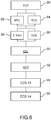
- the figure 6 represents an example of a process implementing the architecture of the figure 5 , process in which different phases of an aircraft's mission can be linked together.
- the airplane When the airplane is immobilized at its parking point, it is generally supplied by a park unit and the HVAC networks 20L and 20R receive energy from the transformer 22.
- a park unit When the airplane is immobilized at its parking point, it is generally supplied by a park unit and the HVAC networks 20L and 20R receive energy from the transformer 22.
- the HVAC networks 20L and 20R receive energy from the transformer 22.
- a first step 80 at least one of the control systems. air conditioning 12 or 14 is powered. Air conditioning is particularly useful when boarding passengers on the plane.
- the aircraft must be able to leave its parking point.
- the park unit is then disconnected and during a step 82, the auxiliary power unit APU is started.
- the APU can be started by taking energy from the park unit before it is disconnected or from the 70L and / or 70R batteries. Starting the APU may only require one of the two 62R or 62L converters. In this case, it is possible to keep one of the air conditioning units 12 or 14 powered.
- the power supply to the air conditioning unit 14 is illustrated by a step 84.
- the start of the APU can typically last from order of one minute. During this time, the inertia of the cabin is sufficient for the degradation of passenger comfort to remain acceptable.
- the airplane After starting the APU, the airplane must be able to move on the ground to the take-off runway. In recent airplanes, this movement can be done by means of the electric machine (s) 76 powering the landing gear (s) 78. electrical machines 76 is performed in step 86.
- the electrical machine (s) 76 may only use one of the two converters 62L or 62R.
- the other converter can be used to supply it to one of the air conditioning systems 12 or 14.
- the power supply to one of the air conditioning systems during the supply of the electrical machine (s) 76 is shown in the figure. figure 5 by a step 88.
- the electrical machine or machines 76 require the two converters 62L or 62R for their operation, it is possible to suspend the operation of the two air conditioning systems 12 and 14. Step 88 is then omitted.
- the main engines 42L and 42R are started successively. More specifically, the 24L electric machine, operating as a motor, starts the 42L main motor. This start-up is represented by a step 90 on the figure 6 . After starting, the main motor 42L can drive the electric machine 24L which then operates as a generator and then supplies the two converters 62L and 62R.
- the 24R electric machine operating as a motor, starts the 42R main motor, which is shown in the figure 5 by a step 92.
- the main motor 42R can drive the electric machine 24R which then operates as a generator and supplies the two converters 62L and 62R.
- the left main engine is started before the right main engine.
- the location to the right or to the left of the aircraft is purely conventional. Without departing from the scope of the invention, it is of course possible to start the right main engine before the left main engine.
- steps 90 and 92 the two converters 62L and 62R are used to successively start the two main engines 42L and 42R.
- steps 90 and 92 the air conditioning systems 12 and 14 are no longer supplied. After starting the two main engines 42L and 42R, the air conditioning systems 12 and 14 are supplied again.
- the coupler 43 can be used. so that the two converters 62L and 62R jointly supply the air conditioning system 12, Then, when the airplane reaches a predetermined altitude during a step 96, the two air conditioning systems 12 and 14 are supplied, each by one of the converters 62L and 62R.
- the figures 7a and 7b show two variants making it possible to supply one of the air conditioning systems, for example the system 12, the air conditioning system 14 not being supplied.
- the power supply of only one of the air conditioning systems can intervene in steps 84, 88 and 94.
- the air conditioning system 12 is powered by the inverters 64L and 66R by means of the magnetic coupler 43.
- the use of a magnetic coupler is advantageous when the number of phases of the inverters 64L and 66R is the same as the number of phases of the electric machine of the air conditioning system 12, in particular the electric machine driving a compressor. It is conventional to use a three-phase electric machine then operating with three-phase inverters also.
- one inverter of each of the converters 62L and 62R is used to supply the air conditioning system 12. This makes it possible to balance the HVAC networks 20L and 20R. Alternatively, when the need for balancing of the HVAC 20L and 20R networks is not necessary or when the inverters not used for the air conditioning system 12 are used for other loads ensuring balancing, it is possible to supply the air conditioning system 12 by two inverters of the same converter.
- the two 64L and 66R inverters directly supply the air conditioning system 12 without a magnetic coupler.
- This variant is advantageous when the number of phases of the electrical machine of the air conditioning system 12 is twice the number of phases of the inverters 64L and 66R.
- the inverters can be three-phase and the electrical machine of the air conditioning system 12 can then be six-phase, which eliminates the need for a coupler.
- the two variants of figures 7a and 7b implement the 62L and 62R converters shown on the figures 3 and 4 . It is also possible to implement these two variants by using the converters 16 and 18 shown on the figures 1 and 2 .
- the figure 8 shows an example of a magnetic coupler 43 suitable for coupling several inverters and more precisely one phase of each inverter.
- the coupler of the figure 8 is duplicated for each of the phases when the inverters are polyphase.
- an inductor In series with a phase of each inverter, denoted here O1, O2 and O3, is connected an inductor.
- three inductors L1, L2 and L3 are shown. The number of inductors is to be adapted according to the number of inverters that one wishes to couple.
- the terminals of inductors L1, L2 and L3 not connected to the inverters O1, O2 and O3 are connected together to form an output phase P of the coupler intended to supply an electrical machine, such as for example that of the air conditioning system 12 or the winding main 24-1.
- One or more contactors K making it possible to temporarily connect the inductors L1, L2 and L3 to each other according to the need for the load supplied by the coupler 43.
- a switch K is shown. Any combination of switches can be implemented to ensure the desired coupling.
- the figure 9 illustrates the control of converters. This control can be implemented in the different embodiments of the electrical architecture. As before, the piloting is illustrated in relation to the converters 62L and 62R represented on the figures 3 and 4 . It is also possible to implement this control for the converters 16 and 18 shown on the figures 1 and 2 .
- a PWM pulse width modulator delivers binary opening and closing orders of electronic switches of each of the inverters.
- An MLI modulator 100L is associated with the converter 62L and controls the inverters 64L and 66L.
- An MLI 100R modulator is associated with the converter 62R and controls the inverters 64R and 66R.
- Each converter can include a close control (not shown) directly connected to the electronic switch grids. belonging to the different inverters. The close commands generate signals adapted to the switches from the binary orders delivered by the modulators 100L and 100R.
- the electrical architecture comprises a module for controlling the current inverter, respectively 102L and 102R.
- a current sensor measures the output current of each inverter and transmits this measurement to the respective module 102L or 102R.
- the current sensor may be located at a filtering element arranged in the converter downstream of the corresponding inverter. The current sensor can perform its measurement on one of the phases or simultaneously on the different phases of the corresponding inverter.
- the module 102L or 102R and the associated current sensor (s) form a servo loop called a current loop receiving a current instruction, respectively 104L or 104R.
- Each module 102L or 102R delivers a duty cycle to each of the PWM modulators so that the current delivered by the corresponding inverter follows the current setpoint 104L and 104R.
- the architecture comprises a module for controlling the operation of the loads supplied by the inverters.
- these modules are respectively referenced 106L and 106R.
- one or more operating sensor measures a parameter characteristic of the operation of the load supplied by each of the inverters. This may for example be the speed of rotation of an engine or the torque that it delivers.
- the operating sensors are respectively referenced 108L and 108R.
- Each load that can be supplied by an inverter having its own operating sensor and the connection of modules 106L and 106R to the associated sensors varies according to the load supplied by the inverter.
- the module 106L or 106R and its associated sensor 108L and 108R form a control loop called the load loop receiving an operating instruction from the load 110L or 110R.
- the load loop modifies the current reference 104R or 104L so that the characteristic parameter of the operation of the load 12 follows the 110L or 110R operating instruction of the load.
- the architecture can include a mode selection module, respectively 112L and 112R.
- This module receives a high level instruction defining the operation of the load.
- the setpoint can define whether the electric machine 24 operates as a generator to supply the HVAC networks or as a motor allowing the associated main motor to be started.
- the high level setpoint can for example define the voltage that the generator must supply.
- This instruction can come from a main engine management system interfacing between the cockpit of the aircraft and the main engine.
- the management system In Anglo-Saxon literature, the management system is often called FADEC for its acronym: “Full Authority Digital Engine Control”.
- the engine management system manages in particular the injection of fuel into the engine turbine as a function of the power demand operated by the pilot through the flight controls.
- the instruction can also come from a system for managing the electrical generators of the aircraft, known in the English literature under the name GCU for its English acronym: “Generator Control Unit”.
- the modules 106L and 112L are shown in solid lines and the modules 106R and 112R are shown in dotted lines.
- a bus 120 on which the various modules 100L, 100R, 102L, 102R, 106L, 106R, 112L and 112R are connected.
- the dotted representation of the modules 106R and 112R illustrates the fact that the two converters 62L and 62R together supply the same load, for example the electric machine 24L or the air conditioning system 12.
- the sensor (s) 108L associated with the supplied load provide a measurement which is only transmitted to the servo module for operation 106L.
- the current setpoint 104L is delivered by the module 106L.
- the 106R module is, for its part, inactive.
- the current setpoint 104R is also generated by the module 106L and is transmitted to the module 102 through the bus 120.
- the MLI 100L modulator can also transmit information to the MLI 100R modulator, including synchronization so that the associated inverters can be more easily coupled.
- the two engines 42L and 42R are started sequentially in steps 94 and 96. It would be possible to pool the modules 106R and 106L so as to have only a single module in the electrical architecture of the aircraft. However, it is advantageous to avoid crossings between the right and left equipment items of the aircraft. Each converter therefore has its 106R or L and 112R or L modules. When powering the electrical machine 24R, the 106R and 110R modules are active and transmit their reference and their synchronization via the bus 120 to the servo module in current 102L and to the PWM modulator 100L.
- the left converter 62L and its control means operate as master.
- the right converter 62R and its control means operate as a slave during their contribution to the supply of the left load.
- the right converter 62R and its piloting means operate as a master while the left converter 62L and its piloting means function as a slave during their contribution to the right load power supply.
Landscapes
- Engineering & Computer Science (AREA)
- Aviation & Aerospace Engineering (AREA)
- Mechanical Engineering (AREA)
- Power Engineering (AREA)
- Combustion & Propulsion (AREA)
- Chemical & Material Sciences (AREA)
- Pulmonology (AREA)
- General Health & Medical Sciences (AREA)
- Health & Medical Sciences (AREA)
- General Engineering & Computer Science (AREA)
- Electric Propulsion And Braking For Vehicles (AREA)
- Control Of Ac Motors In General (AREA)
- Control Of Multiple Motors (AREA)
- Air-Conditioning For Vehicles (AREA)
Description
L'invention concerne une architecture d'aéronef, un aéronef comprenant l'architecture et un procédé de fonctionnement de l'architecture.The invention relates to an aircraft architecture, an aircraft comprising the architecture and a method of operating the architecture.
Dans le domaine aéronautique, la tendance actuelle est d'augmenter le nombre d'équipements électriques et donc la puissance électrique embarquée. Un avion comprend généralement un grand nombre de charges électriques alimentées en puissance électrique par un réseau de fourniture électrique de bord, par exemple, les systèmes de climatisation et les machines électriques permettant de démarrer les moteurs principaux de l'avion. Ces charges mettent en œuvre principalement des machines électriques alternatives polyphasées. L'énergie électrique fournie à ces machines provient de convertisseurs de puissance reliés à un réseau de bord délivrant de l'énergie électrique sous forme continue ou alternative. Le réseau de bord peut comprendre par exemple des générateurs électriques, des batteries de stockage, ou encore des moyens de liaison à un réseau d'alimentation électrique externe à l'avion et permettant l'alimentation électrique de l'avion lorsqu'il est stationné dans un aéroport. De façon courante à bord d'avion, on trouve des réseaux continus 540V et/ou des réseaux alternatifs 115V ou 230V 400Hz.In the aeronautical field, the current trend is to increase the number of electrical equipment and therefore the on-board electrical power. An airplane generally comprises a large number of electrical loads supplied with electrical power by an on-board electrical supply network, for example, the air conditioning systems and the electrical machines making it possible to start the main engines of the airplane. These loads mainly use alternating polyphase electrical machines. The electrical energy supplied to these machines comes from power converters connected to an on-board network delivering electrical energy in direct or alternating form. The on-board network may for example comprise electric generators, storage batteries, or even means of connection to an electric power supply network external to the aircraft and allowing the aircraft to be supplied with electricity when it is parked. at an airport. Commonly on board aircraft, there are 540V DC networks and / or 115V or 230V 400Hz AC networks.
Les équipements embarqués sont de nature très variée et leur consommation énergétique est très variable dans le temps. A titre d'exemple, les systèmes de climatisation sont en fonctionnement quasi continu alors que les machines électriques permettant de démarrer les moteurs principaux ne fonctionnent qu'avant le décollage et durant un laps de temps très court.The on-board equipment is very varied in nature and its energy consumption varies greatly over time. By way of example, the air conditioning systems are in almost continuous operation while the electric machines making it possible to start the main engines only operate before takeoff and for a very short period of time.
Les convertisseurs de puissance reçoivent de l'énergie du réseau de bord pour la convertir en énergie alternative polyphasée adaptée aux exigences en puissance et en fréquence de la charge. Cette adaptation entre les convertisseurs et les charges entraine souvent la réalisation de convertisseurs dédiés aux charges.The power converters receive energy from the on-board network to convert it into polyphase alternating energy suited to the power and frequency requirements of the load. This adaptation between the converters and the loads often leads to the creation of converters dedicated to the loads.
On a cherché à mutualiser les convertisseurs lorsque les charges associées ne fonctionnent pas simultanément. Cependant les systèmes de climatisation doivent fonctionner en permanence et en première approche, il ne parait pas possible d'interrompre leur fonctionnement en utilisant les convertisseurs associés pour d'autres charges. De plus, pour mutualiser un convertisseur, il est préférable que les charges différentes que l'on peut alimenter par ce convertisseur consomment des puissances voisines. En effet, lorsque plusieurs charges sont associées à un même convertisseur, il est nécessaire de dimensionner le convertisseur en fonction de la charge consommant le plus de puissance. Le document
Le document
Le document
Le document
Le document
D'autres systèmes de distribution d'énergie pour les avions sont connus d'après les documents
L'invention a pour but de mutualiser des convertisseurs afin de les utiliser pour des charges dissemblables, notamment le système de climatisation et les machines électriques assurant le démarrage des moteurs principaux. L'invention peut être mise en œuvre dans tout type d'aéronef possédant plusieurs convertisseurs.The object of the invention is to pool converters in order to use them for dissimilar loads, in particular the air conditioning system and the electrical machines ensuring the starting of the main motors. The invention can be implemented in any type of aircraft having several converters.
A cet effet, l'invention a pour objet une architecture électrique d'un aéronef comprenant deux systèmes de climatisation, deux convertisseurs destinés chacun à alimenter un des systèmes de climatisation et au moins une première machine électrique assurant le démarrage d'un premier moteur principal de l'aéronef. Selon l'invention, l'architecture électrique est configurée pour que les deux convertisseurs puissent alimenter conjointement la première machine électrique.To this end, the invention relates to an electrical architecture of a aircraft comprising two air conditioning systems, two converters each intended to supply one of the air conditioning systems and at least a first electrical machine ensuring the starting of a first main engine of the aircraft. According to the invention, the electrical architecture is configured so that the two converters can jointly power the first electrical machine.
Selon l'invention, chacun des deux convertisseurs comprend au moins deux onduleurs ; l'architecture comprend en outre un coupleur permettant d'associer au moins deux premiers des onduleurs ; la machine électrique comprend un enroulement principal pouvant être alimenté par le coupleur et un enroulement d'excitatrice pouvant être alimenté par un second des onduleurs.According to the invention, each of the two converters comprises at least two inverters; the architecture further comprises a coupler making it possible to associate at least two first of the inverters; the electrical machine comprises a main winding which can be supplied by the coupler and an exciter winding which can be supplied by a second of the inverters.
Avantageusement, en dessous d'une altitude prédéterminée, les deux convertisseurs sont configurés pour n'alimenter qu'un seul des deux systèmes de climatisation.Advantageously, below a predetermined altitude, the two converters are configured to supply only one of the two air conditioning systems.
Avantageusement, un onduleur de chaque convertisseur peut alimenter un ventilateur de recirculation d'air.Advantageously, an inverter of each converter can supply an air recirculation fan.
Avantageusement, un onduleur d'au moins un des convertisseurs peut alimenter un moteur électrique de propulsion d'une roue de l'aéronef.Advantageously, an inverter of at least one of the converters can supply an electric motor for propelling a wheel of the aircraft.
L'architecture électrique peut comprendre une seconde machine électrique assurant le démarrage d'un second moteur principal de l'aéronef. Avantageusement, l'architecture électrique est configurée pour que les deux convertisseurs puissent alimenter conjointement la première machine électrique ou la seconde machine électrique.The electrical architecture may include a second electrical machine ensuring the starting of a second main engine of the aircraft. Advantageously, the electrical architecture is configured so that the two converters can jointly power the first electrical machine or the second electrical machine.
Avantageusement, l'architecture comprend un premier module de pilotage associé à un premier des deux convertisseurs, un second module de pilotage associé à un second des deux convertisseurs et un bus mettant en communication les premier et second modules de pilotage ; l'architecture est alors configurée de façon à rendre le premier convertisseur et le premier module de pilotage maîtres lors de l'alimentation conjointe de la première machine électrique, le second convertisseur et le second module de pilotage étant esclaves ; l'architecture est configurée de façon à rendre le second convertisseur et le second module de pilotage maitres lors de l'alimentation conjointe de la seconde machine électrique, le premier convertisseur et le premier module de pilotage étant esclaves.Advantageously, the architecture comprises a first control module associated with a first of the two converters, a second control module associated with a second of the two converters and a bus placing the first and second control modules in communication; the architecture is then configured so as to make the first converter and the first control module masters when the first electrical machine is supplied together, the second converter and the second control module being slaves; the architecture is configured so as to make the second converter and the second control module masters during the joint power supply of the second electrical machine, the first converter and the first control module being slaves.
Avantageusement, l'architecture comprend un groupe auxiliaire de puissance et une machine électrique de démarrage du groupe auxiliaire de puissance ; l'architecture électrique est alors configurée pour que les deux convertisseurs puissent alimenter la machine électrique de démarrage du groupe auxiliaire de puissance.Advantageously, the architecture comprises an auxiliary power unit and an electric machine for starting the auxiliary power unit; the electrical architecture is then configured so that the two converters can supply the electrical starting machine of the auxiliary power unit.
Avantageusement, l'architecture comprend au moins une batterie de stockage d'énergie électrique ; la machine électrique de démarrage du groupe auxiliaire de puissance est alors alimentée par la batterie au travers des convertisseurs.Advantageously, the architecture comprises at least one electric energy storage battery; the electric starting machine of the auxiliary power unit is then supplied by the battery through the converters.
L'invention a également pour objet un aéronef comprenant une architecture électrique selon l'invention.The subject of the invention is also an aircraft comprising an electrical architecture according to the invention.
L'invention a encore pour objet un procédé de fonctionnement d'une architecture électrique selon l'invention dans laquelle la première et la seconde machines électriques sont configurées pour permettre un fonctionnement en moteur ou en générateur permettant d'alimenter les deux convertisseurs, le procédé étant caractérisé en ce qu'il consiste à alimenter la première machine électrique fonctionnant en moteur pour démarrer le premier moteur principal jusqu'à ce que la première machine électrique fonctionne en générateur recevant de l'énergie mécanique du premier moteur principal, la première machine électrique alimentant alors les deux convertisseurs, en ce que le procédé consiste ensuite à alimenter la seconde machine électrique fonctionnant en moteur pour démarrer le second moteur principal.The subject of the invention is also a method of operating an electrical architecture according to the invention in which the first and the second electric machines are configured to allow operation as a motor or as a generator making it possible to supply the two converters, the method being characterized in that it consists in supplying the first electric machine operating as a motor to start the first main motor until the first electric machine operates as a generator receiving mechanical energy from the first main motor, the first electric machine then supplying the two converters, in that the method then consists in supplying the second operating electric machine as a motor to start the second main motor.
Avantageusement, la machine électrique de démarrage du groupe auxiliaire de puissance est configurée pour permettre un fonctionnement en moteur ou en générateur permettant d'alimenter les deux convertisseurs et le procédé consiste à alimenter la machine électrique de démarrage du groupe auxiliaire de puissance fonctionnant en moteur pour démarrer le groupe auxiliaire de puissance à partir de la batterie jusqu'à ce que la machine électrique de démarrage du groupe auxiliaire de puissance recevant de l'énergie mécanique du groupe auxiliaire de puissance fonctionne en générateur pour alimenter les deux convertisseurs ; le procédé consiste ensuite à alimenter la première machine électrique fonctionnant en moteur pour démarrer le premier moteur principal.Advantageously, the electrical starting machine of the auxiliary power unit is configured to allow operation as a motor or as a generator making it possible to supply the two converters and the method consists in supplying the electrical starting machine of the auxiliary power unit operating as a motor for starting the auxiliary power unit from the battery until the electrical starting machine of the auxiliary power unit receiving mechanical energy from the auxiliary power unit operates as a generator to supply the two converters; the method then consists in supplying the first electric machine operating as a motor to start the first main motor.
Avantageusement, le procédé consiste à alimenter le moteur électrique de propulsion d'une roue de l'aéronef après démarrage du groupe auxiliaire de puissance et avant démarrage du premier moteur principal par la première machine électrique.Advantageously, the method consists in supplying the electric motor for propelling a wheel of the aircraft after starting the auxiliary power unit and before starting the first main motor by the first electric machine.
L'invention sera mieux comprise et d'autres avantages apparaîtront à la lecture de la description détaillée d'un mode de réalisation donné à titre d'exemple, description illustrée par le dessin joint dans lequel :
- les
figures 1 et 2 représentent un premier mode de réalisation d'une architecture électrique d'un aéronef ; - les
figures 3 et 4 représentent un second mode de réalisation d'une architecture électrique d'un aéronef ; - la
figure 5 représente schématiquement une architecture électrique d'un aéronef bimoteur ; - la
figure 6 représente un exemple de procédé mettent en œuvre l'architecture de lafigure 5 ; - les
figures 7a et 7b représentent deux variantes permettant d'alimenter un système de climatisation de l'aéronef ; - la
figure 8 représente un exemple de coupleur magnétique ; - la
figure 9 représente le pilotage de convertisseurs de l'architecture électrique.
- the
figures 1 and 2 represent a first embodiment of an electrical architecture of an aircraft; - the
figures 3 and 4 show a second embodiment of an electrical architecture of an aircraft; - the
figure 5 schematically represents an electrical architecture of a twin-engine aircraft; - the
figure 6 represents an example of a process implementing the architecture of thefigure 5 ; - the
figures 7a and 7b represent two variants making it possible to supply an air conditioning system of the aircraft; - the
figure 8 represents an example of a magnetic coupler; - the
figure 9 represents the control of converters of the electrical architecture.
Par souci de clarté, les mêmes éléments porteront les mêmes repères dans les différentes figures.For the sake of clarity, the same elements will bear the same references in the different figures.
La
Chacun des convertisseurs 16 et 18 permet d'adapter la tension et la fréquence du bus HVAC aux systèmes de climatisation 12 et 14. De façon plus générale, les convertisseurs 16 et 18 permettent de prélever de la puissance d'un réseau de bord pour alimenter les systèmes de climatisation 12 et 14. Le réseau de bord peut être alternatif, comme dans l'exemple représenté ou continu.Each of the
Chacun des convertisseurs 16 et 18 comprend au moins un onduleur permettant d'alimenter le système de climatisation associé. Dans l'exemple représenté, le convertisseur 16 comprend un onduleur 26 et le convertisseur 18, un onduleur 28. De façon classique, les onduleurs 26 et 28 sont des onduleurs triphasés. L'invention peut être mise en œuvre quel que soit le nombre de phases. Chacun des onduleurs 26 et 28 reçoit de l'énergie d'un bus continu appelé bus HVDC pour son acronyme anglo-saxon : « High Voltage Direct Current », respectivement 30 et 32. A bord d'aéronefs, on trouve souvent des bus 270V DC ou 540V DC. Toute autre tension continue peut bien entendu être mise en œuvre dans le cadre de l'invention. Chaque convertisseur 16 et 18 peut comprendre un redresseur, respectivement 34 et 36 recevant de l'énergie du bus HVAC 20 et alimentant le bus HVDC respectif 30 ou 32. Chaque convertisseur peut comprendre des éléments de filtrage, notamment en sortie des onduleurs 26 et 28 et/ou en entrée des redresseurs 34 et 36.Each of the
Chaque convertisseur 16 et 18 peut comprendre un second onduleur, respectivement 38 et 40 alimentés par le bus HVDC de son convertisseur et permettant d'alimenter d'autres charges de l'aéronef. Les deux onduleurs d'un même convertisseur peuvent être dimensionnés différemment. Dans l'exemple représenté, sur la
L'invention n'est pas limitée à deux onduleurs par convertisseurs. En fonction du besoin, il peut y avoir plus de deux onduleurs dans chacun des convertisseurs 16 et 18.The invention is not limited to two inverters per converter. Depending on the need, there can be more than two inverters in each of the
Les convertisseurs 16 et 18 peuvent être utilisés à d'autres fins, notamment pour démarrer les moteurs principaux de l'avion. Par exemple, lorsque l'avion possède deux moteurs principaux, à chacun d'eux est associé une machine électrique fonctionnant en moteur et permettant de le démarrer. La machine électrique peut être réversible. Autrement dit, elle peut aussi fonctionner en génératrice lorsque le moteur associé est en fonctionnement tel le générateur 24 représenté sur la
Sur la
L'avion comprend généralement plusieurs moteurs principaux, en général deux ou quatre pour les avions gros porteurs. Le démarrage des moteurs peut se faire séquentiellement. Plus précisément, les convertisseurs 16 et 18 alimentent une première machine électrique 24 associée à un premier moteur principal à partir d'énergie provenant de l'APU ou d'une batterie de l'avion. Une fois le premier moteur démarré, sa machine électrique associée peut générer du courant pour alimenter le bus HVAC. Ensuite seulement, les convertisseurs 16 et 18 sont déconnectés de la machine électrique 24 du premier moteur principal pour être connectés à une autre machine électrique associée à un second moteur principal de l'avion et ainsi de suite jusqu'au démarrage de l'ensemble des moteurs de l'avion. Pendant cette phase de démarrage des moteurs les systèmes de climatisation 12 et 14 ne sont pas alimentés. L'inertie thermique de la cabine permet d'accepter cette coupure momentanée d'alimentation qui reste de l'ordre d'une minute.The aircraft generally has several main engines, usually two or four for large aircraft. The engines can be started sequentially. More precisely, the
Selon l'invention, la machine électrique 24 comprend deux enroulements séparés : un enroulement principal 24-1 et un enroulement d'excitatrice 24-2. L'enroulement principal 24-1 nécessite beaucoup plus de puissance que l'enroulement d'excitatrice 24-2. Dans l'exemple représenté, les deux onduleurs 26 et 28 sont couplés pour alimenter l'enroulement principal 24-1. L'enroulement d'excitatrice 24-2 ne nécessite, quant à lui, que la puissance délivrée par l'onduleur 38. Le couplage des deux onduleurs 26 et 28 peut être assuré par un coupleur magnétique 43.According to the invention, the
L'architecture électrique 10 comprend des contacteurs commandés, non représentés et permettant de passer du mode de fonctionnement de la
Dans le mode de fonctionnement de la
Les
Sur la
Comme pour le mode de réalisation de la
Sur la
La
On retrouve deux convertisseurs, référencés ici 62L et 62R. On retrouve dans le convertisseur 62L, un bus HVDC 30L et un redresseur 34L alimenté par un bus HVAC 20L. De même on retrouve dans le convertisseur 62R, un bus HVDC 30R et un redresseur 34R alimenté par un bus HVAC 20R. Les bus HVAC 20L et 20R peuvent être connectés pour former ensemble le bus HVAC 20 décrit précédemment. La connexion entre les deux bus HVAC 20L et 20R peut être permanente ou pilotable, notamment en cours d'utilisation, afin de permettre de dissocier les bus HVAC 20L et 20R en cas de panne d'un composant associé à l'un des bus et pouvant se propager à l'ensemble des équipements droits ou gauches de l'avion.There are two converters, referenced here 62L and 62R. In the 62L converter, we find an
Comme précédemment décrit, l'architecture 60 peut être connectée à un groupe de parc lorsque l'avion et au sol. La connexion se fait par un des bus HVAC 20L et 20R éventuellement par l'intermédiaire du transformateur ou autotransformateur 22. Sur la
Dans chacun des convertisseurs 62L et 62R, le bus HVDC alimente deux onduleurs, respectivement 64L et 66L pour le convertisseur 62L et, 64R et 66R pour le convertisseur 62R. Les deux onduleurs d'un même convertisseur peuvent être différents comme dans le mode de réalisation des
Associé à chaque moteur principal 42L et 42R on retrouve une machine électrique, respectivement 24L et 24R pouvant fonctionner en moteur pour démarrer le moteur principal associé et pouvant fonctionner en générateur pour alimenter des bus HVAC 20L ou 20R.Associated with each
L'avion peut également être équipé d'un groupe auxiliaire de puissance APU et d'une machine électrique 74 de démarrage de l'APU. Comme pour les machines électriques 24L et 24R, la machine électrique 74 peut fonctionner en moteur pour démarrer l'APU ou en générateur, une fois l'APU démarré pour alimenter l'architecture électrique 60, par exemple au niveau d'un des bus HVAC 20L ou 20R. La connexion de la machine électrique 74 peut alternativement se faire à un autre point de l'architecture 60, par exemple au niveau d'un des bus HVDC 30L ou 30R, ou niveau d'un des bus LVDC 72L ou 72R.The airplane can also be equipped with an APU auxiliary power unit and an
Sur la
Dans l'architecture 60, on retrouve également les systèmes de climatisation 12 et 14 alimentés respectivement par les convertisseurs 62L et 62R.In
Dans de nombreux avions équipés de deux systèmes de climatisation, ceux-ci peuvent ne pas être tous deux mis en œuvre durant le vol. Plus précisément, il peut être utile de ne mettre en œuvre qu'un seul des deux systèmes de climatisation en dessous d'une altitude prédéterminée. Il est possible de n'utiliser qu'un seul des deux convertisseurs 62L et 62R pour alimenter le système de climatisation retenu. L'autre des deux convertisseurs n'étant pas utilisé pour la climatisation. Alternativement, il est avantageux d'équilibrer l'utilisation des deux convertisseurs 62L et 62R. Il est alors souhaitable d'alimenter le système de climatisation retenu à partir des deux convertisseurs couplés. Le couplage peut être réalisé en utilisant un coupleur dédié ou en réutilisant le coupleur 43 n'est plus utilisé après démarrage des moteurs principaux 42L et 42R.In many airplanes equipped with two air conditioning systems, both may not be activated during flight. More specifically, it may be useful to implement only one of the two air conditioning systems below a predetermined altitude. It is possible to use only one of the two
Pour assurer son déplacement au sol, notamment depuis une place de parking jusqu'à la piste de décollage, entre deux places de parking ou depuis la piste d'atterrissage jusqu'à une place de parking, l'avion utilise généralement ses moteurs principaux : turboréacteur, turbopropulseurs alimentés au moyen de carburant. Ces moteurs sont polluants et sont source de nuisances sonores. Pour assurer le déplacement au sol, il est possible d'équiper le ou les trains d'atterrissage de l'avion de moteurs électriques pouvant entraîner ses roues afin de permettre le déplacement de l'avion. Sur la
Sur la
La
Lorsque l'avion est immobilisé à son point de stationnement, il est généralement alimenté par un groupe de parc et les réseaux HVAC 20L et 20R reçoivent de l'énergie par le transformateur 22. Dans une première étape 80, au moins un des systèmes de climatisation 12 ou 14 est alimenté. La climatisation est notamment utile lors de l'embarquement des passagers à bord de l'avion.When the airplane is immobilized at its parking point, it is generally supplied by a park unit and the
Une fois l'embarquement terminé, l'avion doit pouvoir quitter son point de stationnement. Le groupe de parc est alors déconnecté et lors d'une étape 82, le groupe auxiliaire de puissance APU est démarré. Le démarrage de l'APU peut se faire en prélevant de l'énergie du groupe de parc avant sa déconnexion ou des batteries 70L et/ou 70R. Le démarrage de l'APU peut ne nécessiter qu'un seul des deux convertisseurs 62R ou 62L. Dans ce cas, il possible de conserver un des groupes de climatisation 12 ou 14 alimenté. L'alimentation du groupe de climatisation 14 est illustrée par une étape 84. Alternativement, durant l'étape 82, il est possible couper l'alimentation du ou des groupes de climatisation 12 et 14. Le démarrage de l'APU peut durer typiquement de l'ordre d'une minute. Durant ce laps de temps, l'inertie de la cabine est suffisante pour que la dégradation du confort des passagers reste acceptable.Once boarding is complete, the aircraft must be able to leave its parking point. The park unit is then disconnected and during a
Après démarrage de l'APU, l'avion doit être en mesure de se déplacer au sol jusqu'à la piste de décollage. Dans les avions récents, ce déplacement peut se faire au moyen de la ou des machines électriques 76 motorisant le ou les trains d'atterrissage 78. L'alimentation de la ou des machines électriques 76 est réalisée à l'étape 86. La ou les machines électriques 76 peuvent n'utiliser qu'un des deux convertisseurs 62L ou 62R. L'autre convertisseur peut être utilisé pour l'alimenter un des systèmes de climatisation 12 ou 14. L'alimentation d'un des systèmes de climatisation durant l'alimentation de la ou des machines électriques 76 est représentée sur la
Avant le décollage les moteurs principaux 42L et 42R sont démarrés successivement. Plus précisément, la machine électrique 24L, fonctionnant en moteur, démarre le moteur principal 42L. Ce démarrage est représenté par une étape 90 sur la
Ensuite, la machine électrique 24R, fonctionnant en moteur, démarre le moteur principal 42R, ce qui est illustré sur la
De façon classique, dans les avions bimoteurs, le moteur principal gauche est démarré avant le moteur principal droit. La localisation à droite ou à gauche de l'avion, est purement conventionnelle. Sans sortir du cadre de l'invention, il est bien entendu possible démarrer le moteur principal droit avant le moteur principal gauche.Conventionally, in twin-engine airplanes, the left main engine is started before the right main engine. The location to the right or to the left of the aircraft is purely conventional. Without departing from the scope of the invention, it is of course possible to start the right main engine before the left main engine.
Lors des étapes 90 et 92, les deux convertisseurs 62L et 62R sont utilisés pour démarrer successivement les deux moteurs principaux 42L et 42R. Durant les étapes 90 et 92, les systèmes de climatisation 12 et 14 ne sont plus alimentés. Après démarrage des deux moteurs principaux 42L et 42R, les systèmes de climatisation 12 et 14 sont à nouveau alimentés.During
Il est possible de dissocier l'alimentation des deux systèmes de climatisation 12 et 14. Seul un des deux systèmes, par exemple le système de climatisation 12 est alimenté lors d'une étape 94. Comme évoqué plus haut, le coupleur 43 peut être utilisé pour que les deux convertisseurs 62L et 62R alimentent conjointement le système de climatisation 12, Ensuite, lorsque l'avion atteint une altitude prédéterminée lors d'une étape 96, les deux systèmes de climatisation 12 et 14 sont alimentés, chacun par un des convertisseurs 62L et 62R.It is possible to separate the power supply from the two
Les
Sur la
Les deux variantes des
Par ailleurs, dans les deux variantes des
La
En série avec une phase de chaque onduleur, notés ici O1, O2 et O3, est raccordé une inductance. Sur la
La
Associé à chaque convertisseur 62L et 62R et plus précisément à chaque onduleur, un modulateur de largeur d'impulsions MLI délivre des ordres binaires d'ouverture et de fermeture d'interrupteurs électroniques de chacun des onduleurs. Un modulateur MLI 100L est associé au convertisseur 62L et pilote les onduleurs 64L et 66L. Un modulateur MLI 100R est associé au convertisseur 62R et pilote les onduleurs 64R et 66R. Chaque convertisseur peut comprendre une commande rapprochée (non représentée) directement connectée aux grilles d'interrupteurs électroniques appartenant aux différents onduleurs. Les commandes rapprochées génèrent des signaux adaptés aux interrupteurs à partir des ordres binaires délivrés par les modulateurs 100L et 100R.Associated with each
En amont de chacun des modulateurs de largeur d'impulsions 100L et 100R, l'architecture électrique comprend un module d'asservissement de l'onduleur en courant, respectivement 102L et 102R. Un capteur de courant mesure le courant de sortie de chaque onduleur et transmet cette mesure au module respectif 102L ou 102R. Le capteur de courant peut être situé au niveau d'un élément de filtrage disposé dans le convertisseur en aval de l'onduleur correspondant. Le capteur de courant peut réaliser sa mesure sur l'une des phases ou simultanément sur les différentes phases de l'onduleur correspondant. Le module 102L ou 102R et le ou les capteurs de courant associés forment une boucle d'asservissement appelée boucle de courant recevant une consigne en courant, respectivement 104L ou 104R. Chaque module 102L ou 102R délivre un rapport cyclique à chacun des modulateurs MLI pour que le courant délivré par l'onduleur correspondant suive la consigne en courant 104L et 104R.Upstream of each of the
En amont de chacun des modules 102L et 102R, l'architecture comprend un module d'asservissement du fonctionnement des charges alimentées par les onduleurs. Sur la
Le module 106L ou 106R et son capteur 108L et 108R associé forme une boucle d'asservissement appelée boucle de charge recevant une consigne de fonctionnement de la charge 110L ou 110R. La boucle de charge modifie la consigne en courant 104R ou 104L pour que le paramètre caractéristique du fonctionnement de la charge 12 suive la consigne 110L ou 110R de fonctionnement de la charge.The
En amont de chaque module 106L et 106R, l'architecture peut comprendre un module de sélection de mode, respectivement 112L et 112R. Ce module reçoit une consigne de haut niveau définissant le fonctionnement de la charge. Par exemple pour la machine électrique 24 associée à un moteur principal, la consigne peut définir si la machine électrique 24 fonctionne en générateur pour alimenter les réseaux HVAC ou en moteur permettant de démarrer le moteur principal associé. En mode générateur, la consigne de haut niveau peut par exemple définir la tension que doit fournir le générateur.Upstream of each
Cette consigne peut provenir d'un système de gestion du moteur principal s'interfaçant entre le cockpit de l'aéronef et le moteur principal. Dans la littérature anglo-saxonne, le système de gestion est souvent appelé FADEC pour son acronyme anglais : « Full Authority Digital Engine Control ». Le système de gestion du moteur gère notamment l'injection de carburant dans la turbine du moteur en fonction de la demande de puissance opérée par le pilote au travers des commandes de vol. La consigne peut également provenir d'un système de gestion des générateurs électriques de l'aéronef, connu dans la littérature anglo-saxonne sous le nom de GCU pour son acronyme anglais : « Generator Control Unit ».This instruction can come from a main engine management system interfacing between the cockpit of the aircraft and the main engine. In Anglo-Saxon literature, the management system is often called FADEC for its acronym: “Full Authority Digital Engine Control”. The engine management system manages in particular the injection of fuel into the engine turbine as a function of the power demand operated by the pilot through the flight controls. The instruction can also come from a system for managing the electrical generators of the aircraft, known in the English literature under the name GCU for its English acronym: “Generator Control Unit”.
Sur la
Dans ce mode de fonctionnement, seuls le ou les capteurs 108L associés à la charge alimentée fournissent une mesure qui n'est transmise qu'au module d'asservissement du fonctionnement 106L. La consigne en courant 104L est délivrée par le module 106L. Le module 106R est, quant à lui, inactif. La consigne en courant 104R est également générée par le module 106L et est transmise au module 102 au travers du bus 120.In this operating mode, only the sensor (s) 108L associated with the supplied load provide a measurement which is only transmitted to the servo module for
Le modulateur MLI 100L peut également transmettre des informations au modulateur MLI 100R, notamment une synchronisation afin que les onduleurs associés puissent être plus facilement couplés.The
Le démarrage des deux moteurs 42L et 42R se fait séquentiellement aux étapes 94 et 96. Il serait possible de mutualiser les modules 106R et 106L pour ne disposer que d'un seul module dans l'architecture électrique de l'aéronef. Cependant, il est avantageux d'éviter les croisements entre les équipements droit et gauche de l'aéronef. Ainsi chaque convertisseur dispose de ses modules 106R ou L et 112R ou L. Lors de l'alimentation de la machine électrique 24R, les modules 106R et 110R sont actif et transmettent leur consigne et leur synchronisation par le bus 120 au module d'asservissement en courant 102L et au modulateur MLI 100L.The two
Pour assurer le pilotage des convertisseurs, le découpage proposé en différents modules n'est donné qu'à titre d'exemple. D'autres découpages ou boucles d'asservissement peuvent apparaitre. La distinction fonctionnelle entre les différents modules associés à chacun des convertisseurs peut varier sans sortir du cadre de l'invention.To ensure the control of the converters, the division proposed into different modules is given only by way of example. Other cutouts or control loops may appear. The functional distinction between the different modules associated with each of the converters can vary without departing from the scope of the invention.
De façon plus générale, lors de l'alimentation d'une charge gauche de l'aéronef, notamment, le moteur principal gauche 42L ou le système de climatisation gauche 12, le convertisseur gauche 62L et ses moyens de pilotage fonctionnent en maître. Le convertisseur droit 62R et ses moyens de pilotage fonctionnent en esclave lors de leur contribution à l'alimentation de la charge gauche. Inversement, lors de l'alimentation d'une charge droite de l'aéronef, le convertisseur droit 62R et ses moyens de pilotage fonctionnent en maître tandis que le convertisseur gauche 62L et ses moyens de pilotage fonctionnent en esclave lors de leur contribution à l'alimentation de la charge droite.More generally, when supplying a left load of the aircraft, in particular, the left
Claims (12)
- An electrical architecture for an aircraft comprising two air-conditioning systems (12, 14), two converters (16, 18; 46, 48; 62L, 62R), each intended to power one of the air-conditioning systems (12, 14), and comprising at least one first electric machine (24; 24L) which starts up a first main engine (42; 42L) of the aircraft, and wherein each of the two converters (16, 18; 46, 48; 62L, 62R) comprises two inverters (26, 28, 38, 40; 50, 52, 54, 56; 64L, 66L, 64R, 66R), characterized in that the electrical architecture (10; 47; 60) is configured such that the two converters (16, 18; 46, 48; 62L, 62R) can together power the first electric machine (24; 24L), in that the electrical architecture (10; 47; 60) further comprises a coupler (43) for linking at least two first of the inverters, and in that the electric machine (24) comprises a main winding (24-1) that can be powered by the coupler (43) and an exciter winding (24-2) that can be powered by a second one of the inverters.
- The electrical architecture according to claim 1, characterized in that, below a predetermined altitude, the two converters (16, 18; 46, 48; 62L, 62R) are configured to only power one of the two air-conditioning systems (12, 14).
- The electrical architecture according to one of the preceding claims, characterized in that an inverter of each converter (16, 18; 46, 48; 62L, 62R) is configured to power an air recirculation fan (44, 45).
- The electrical architecture according to one of the preceding claims, characterized in that an inverter (64L) of at least one of the converters (62L) is configured to power an electric motor (76) for powering a wheel (78) of the aircraft.
- The electrical architecture according to one of the preceding claims, characterized in that it further comprises a second electric machine (24R) that starts up a second main engine (42R) of the aircraft, and in that the electrical architecture (60) is configured such that the two converters (62L, 62R) can together power the first electric machine (24L) or the second electric machine (24R).
- The electrical architecture according to claim 5, characterized in that the architecture comprises a first driver module (100L, 102L, 106L, 112L) associated with a first one of the two converters (62L), a second driver module (100R, 102R, 106R, 112R) associated with a second one of the two converters (62R) and a bus (120) connecting the first and second driver modules, in that the architecture is configured to make the first converter (62L) and the first driver module (100L, 102L, 106L, 112L) masters during combined powering of the first electric machine (24L), the second converter (62R) and the second driver module (100R, 102R, 106R, 112R) being slaves, and in that the architecture is configured so as to make the second converter (62R) and the second driver module (100R, 102R, 106R, 112R) masters during combined powering of the second electric machine (24R), the first converter (62L) and the first driver module (100L, 102L, 106L, 112L) being slaves.
- The electrical architecture according to one of the preceding claims, characterized in that it comprises an auxiliary power unit (APU) and an electric machine (74) for starting up the auxiliary power unit (APU), and in that the electrical architecture is configured such that the two converters (62L, 62R) can power the electric machine (74) for starting up the auxiliary power unit (APU).
- The electrical architecture according to claim 7, characterized in that it comprises at least one battery (70L, 70R) for storing electrical energy, and in that the electric machine (74) for starting up the auxiliary power unit (APU) is powered by the battery (70L, 70R) via the converters (62L, 62R).
- An aircraft comprising an electrical architecture according to one of the preceding claims.
- A method for operating an electrical architecture according to claim 5, wherein the first and second electric machines (24L, 24R) are configured so as to allow operation as a motor or as a generator, making it possible to power the two converters (62L, 62R), the method being characterized in that it consists in powering the first electric machine (24L) operating as a motor to start up the first main engine (42L) until the first electric machine (24L) operates as a generator, receiving mechanical energy from the first main engine (42L), the first electric machine (24L) then powering the two converters (62L, 62R), in that the method then consists in powering the second electric machine (24R) operating as a motor in order to start up the second main engine (42R).
- The method according to claim 10 for operating an electrical architecture according to claims 5 to 8, wherein the electric machine (74) for starting up the auxiliary power unit (APU) is configured to allow operation as a motor or as a generator, making it possible to power the two converters (62L, 62R), characterized in that it consists in powering the electric machine (74) for starting up the auxiliary power unit (APU) operating as a motor in order to start up the auxiliary power unit (APU) from the battery (70L, 70R) until the electric machine (74) for starting up the auxiliary power unit (APU) receiving mechanical energy from the auxiliary power unit (APU), operates as a generator to power the two converters (62L, 62R), in that the method then consists in powering the first electric machine (24L) operating as a motor in order to start up the first main engine (42L).
- The method according to claim 11 for operating an electrical architecture according to claims 4 to 8, characterized in that it consists in powering the electric motor (76) for driving a wheel (78) of the aircraft after the auxiliary power unit (APU) has been started up and before starting up of the first main engine (42L) by the first electric machine (24L).
Applications Claiming Priority (1)
| Application Number | Priority Date | Filing Date | Title |
|---|---|---|---|
| FR1800653A FR3082807B1 (en) | 2018-06-22 | 2018-06-22 | AIRCRAFT ELECTRICAL ARCHITECTURE, AIRCRAFT INCLUDING ARCHITECTURE AND ARCHITECTURE OPERATING PROCEDURE |
Publications (2)
| Publication Number | Publication Date |
|---|---|
| EP3588729A1 EP3588729A1 (en) | 2020-01-01 |
| EP3588729B1 true EP3588729B1 (en) | 2020-12-09 |
Family
ID=64049290
Family Applications (1)
| Application Number | Title | Priority Date | Filing Date |
|---|---|---|---|
| EP19181043.1A Active EP3588729B1 (en) | 2018-06-22 | 2019-06-18 | Electrical architecture of an aircraft, aircraft comprising the architecture and operating method of the architecture |
Country Status (7)
| Country | Link |
|---|---|
| US (1) | US11509245B2 (en) |
| EP (1) | EP3588729B1 (en) |
| JP (1) | JP7378977B2 (en) |
| CN (1) | CN110626507B (en) |
| ES (1) | ES2858081T3 (en) |
| FR (1) | FR3082807B1 (en) |
| RU (1) | RU2765513C2 (en) |
Cited By (1)
| Publication number | Priority date | Publication date | Assignee | Title |
|---|---|---|---|---|
| WO2023148451A1 (en) | 2022-02-07 | 2023-08-10 | Safran Electrical & Power | Control unit for controlling the power of at least one battery, aircraft comprising said control unit, and corresponding control method |
Families Citing this family (8)
| Publication number | Priority date | Publication date | Assignee | Title |
|---|---|---|---|---|
| CN112368208A (en) * | 2018-05-31 | 2021-02-12 | 杰欧比飞行有限公司 | Electric power system architecture and fault-tolerant VTOL (virtual volume on-board) aircraft using same |
| US12006048B2 (en) | 2018-05-31 | 2024-06-11 | Joby Aero, Inc. | Electric power system architecture and fault tolerant VTOL aircraft using same |
| US11738881B2 (en) * | 2019-10-21 | 2023-08-29 | Hamilton Sundstrand Corporation | Auxiliary power unit systems |
| FR3121661B1 (en) * | 2021-04-08 | 2024-01-26 | Safran | Configurable power system |
| FR3122787B1 (en) * | 2021-05-07 | 2023-06-16 | Thales Sa | Method for managing the operation of an aircraft electrical power supply system comprising at least one electrical energy storage assembly |
| FR3131278A1 (en) * | 2021-12-27 | 2023-06-30 | Safran Electrical & Power | Electric propulsion system for an aircraft |
| FR3132696B1 (en) | 2022-02-14 | 2024-06-21 | Safran Electrical & Power | DC voltage electrical power distribution device, propulsion system and associated aircraft |
| FR3137621A1 (en) * | 2022-07-08 | 2024-01-12 | Safran Electrical & Power | Battery charging device, propulsion chain, aircraft and associated method |
Family Cites Families (16)
| Publication number | Priority date | Publication date | Assignee | Title |
|---|---|---|---|---|
| SU828606A1 (en) * | 1980-01-10 | 1984-05-15 | Предприятие П/Я А-1665 | Air pressure control system for sealed aircraft cabin |
| US6018233A (en) * | 1997-06-30 | 2000-01-25 | Sundstrand Corporation | Redundant starting/generating system |
| US6992403B1 (en) * | 2001-03-08 | 2006-01-31 | Pacific Scientific | Electric power and start system |
| US7210653B2 (en) * | 2002-10-22 | 2007-05-01 | The Boeing Company | Electric-based secondary power system architectures for aircraft |
| US7109681B2 (en) | 2004-08-25 | 2006-09-19 | Hamilton Sundstrand Corporation | Parallel inverter motor drive with improved waveform and reduced filter requirements |
| US7513119B2 (en) * | 2005-02-03 | 2009-04-07 | The Boeing Company | Systems and methods for starting aircraft engines |
| FR2898871B1 (en) * | 2006-03-24 | 2009-02-06 | Airbus France Sas | SYSTEM AND METHOD FOR POWER SUPPLYING USER SYSTEMS ABOARD AN AIRCRAFT |
| US7612514B2 (en) * | 2006-11-09 | 2009-11-03 | Honeywell International Inc. | Architecture and a multiple function power converter for aircraft |
| US8427001B2 (en) * | 2008-07-30 | 2013-04-23 | Honeywell International, Inc. | Electrically controlled frequency-based power system architecture for aircraft |
| FR2939983B1 (en) | 2008-12-11 | 2010-12-31 | Liebherr Aerospace Toulouse Sas | DEVICE WITH POLYPHASE ELECTRIC MACHINE AND ELECTRIC MACHINE THEREFOR |
| FR2967847B1 (en) * | 2010-11-23 | 2015-06-26 | Hispano Suiza Sa | METHOD AND ARCHITECTURE FOR PROCESSING REGENERATED ELECTRIC ENERGY OF AN AIRCRAFT |
| US9783317B2 (en) * | 2014-08-08 | 2017-10-10 | Honeywell International Inc. | Power converter, generator and architecture for high efficiency auxiliary power unit |
| US20170107910A1 (en) * | 2015-10-15 | 2017-04-20 | Ge Aviation Systems Llc | Method and apparatus for starting an aircraft engine and operating a power architecture for an aircraft |
| FR3046598B1 (en) | 2016-01-11 | 2018-02-02 | Liebherr-Aerospace Toulouse Sas | ELECTRICAL ARCHITECTURE OF AN AIRCRAFT WITH A COOLING PLATE |
| FR3054828B1 (en) | 2016-08-03 | 2018-08-24 | Liebherr-Aerospace Toulouse Sas | ARCHITECTURE OF POWER SUPPLY NETWORK |
| US10608565B2 (en) * | 2017-12-07 | 2020-03-31 | General Electric Company | Systems and methods for rotating a crankshaft to start an engine |
-
2018
- 2018-06-22 FR FR1800653A patent/FR3082807B1/en not_active Expired - Fee Related
-
2019
- 2019-06-18 EP EP19181043.1A patent/EP3588729B1/en active Active
- 2019-06-18 ES ES19181043T patent/ES2858081T3/en active Active
- 2019-06-19 RU RU2019118976A patent/RU2765513C2/en active
- 2019-06-20 US US16/447,722 patent/US11509245B2/en active Active
- 2019-06-21 JP JP2019115212A patent/JP7378977B2/en active Active
- 2019-06-24 CN CN201910548573.0A patent/CN110626507B/en active Active
Cited By (2)
| Publication number | Priority date | Publication date | Assignee | Title |
|---|---|---|---|---|
| WO2023148451A1 (en) | 2022-02-07 | 2023-08-10 | Safran Electrical & Power | Control unit for controlling the power of at least one battery, aircraft comprising said control unit, and corresponding control method |
| FR3132600A1 (en) | 2022-02-07 | 2023-08-11 | Safran Electrical & Power | Battery power control unit, aircraft comprising said control unit and corresponding control method. |
Also Published As
| Publication number | Publication date |
|---|---|
| US20190393809A1 (en) | 2019-12-26 |
| JP7378977B2 (en) | 2023-11-14 |
| RU2019118976A3 (en) | 2022-01-13 |
| EP3588729A1 (en) | 2020-01-01 |
| FR3082807A1 (en) | 2019-12-27 |
| JP2020001691A (en) | 2020-01-09 |
| US11509245B2 (en) | 2022-11-22 |
| RU2019118976A (en) | 2020-12-21 |
| FR3082807B1 (en) | 2021-05-21 |
| CN110626507A (en) | 2019-12-31 |
| ES2858081T3 (en) | 2021-09-29 |
| RU2765513C2 (en) | 2022-01-31 |
| CN110626507B (en) | 2024-03-26 |
Similar Documents
| Publication | Publication Date | Title |
|---|---|---|
| EP3588729B1 (en) | Electrical architecture of an aircraft, aircraft comprising the architecture and operating method of the architecture | |
| CA2667270C (en) | System for generating, converting, distributing and electrically starting on board an aircraft | |
| CA2943486C (en) | Assistance device for a free turbine turbomachine of an aircraft comprising at least two free turbine turbomachines | |
| EP2830938B1 (en) | Aircraft ground power supply system | |
| EP2740191B1 (en) | Device for supplying an aircraft on the ground with electricity | |
| EP2980946B1 (en) | Aircraft electrical network | |
| US11623757B2 (en) | Hybrid electric taxi system (HETS) or full electric taxi system (FETS) | |
| JP6542795B2 (en) | Method and system for rapid reactivation of a turbine engine | |
| EP3276774B1 (en) | An electrical architecture with paired secondary electrical networks for starting engines of an aircraft | |
| EP3100333A1 (en) | Electrical conversion and distribution system for an aircraft | |
| EP3925890B1 (en) | Aircraft electrical architecture |
Legal Events
| Date | Code | Title | Description |
|---|---|---|---|
| PUAI | Public reference made under article 153(3) epc to a published international application that has entered the european phase |
Free format text: ORIGINAL CODE: 0009012 |
|
| STAA | Information on the status of an ep patent application or granted ep patent |
Free format text: STATUS: THE APPLICATION HAS BEEN PUBLISHED |
|
| AK | Designated contracting states |
Kind code of ref document: A1 Designated state(s): AL AT BE BG CH CY CZ DE DK EE ES FI FR GB GR HR HU IE IS IT LI LT LU LV MC MK MT NL NO PL PT RO RS SE SI SK SM TR |
|
| AX | Request for extension of the european patent |
Extension state: BA ME |
|
| TPAC | Observations filed by third parties |
Free format text: ORIGINAL CODE: EPIDOSNTIPA |
|
| STAA | Information on the status of an ep patent application or granted ep patent |
Free format text: STATUS: REQUEST FOR EXAMINATION WAS MADE |
|
| 17P | Request for examination filed |
Effective date: 20200420 |
|
| RBV | Designated contracting states (corrected) |
Designated state(s): AL AT BE BG CH CY CZ DE DK EE ES FI FR GB GR HR HU IE IS IT LI LT LU LV MC MK MT NL NO PL PT RO RS SE SI SK SM TR |
|
| GRAP | Despatch of communication of intention to grant a patent |
Free format text: ORIGINAL CODE: EPIDOSNIGR1 |
|
| STAA | Information on the status of an ep patent application or granted ep patent |
Free format text: STATUS: GRANT OF PATENT IS INTENDED |
|
| RIC1 | Information provided on ipc code assigned before grant |
Ipc: B64C 25/40 20060101ALI20200630BHEP Ipc: B64D 13/06 20060101ALI20200630BHEP Ipc: H02J 3/38 20060101AFI20200630BHEP Ipc: B64D 33/00 20060101ALI20200630BHEP |
|
| INTG | Intention to grant announced |
Effective date: 20200717 |
|
| GRAS | Grant fee paid |
Free format text: ORIGINAL CODE: EPIDOSNIGR3 |
|
| GRAA | (expected) grant |
Free format text: ORIGINAL CODE: 0009210 |
|
| STAA | Information on the status of an ep patent application or granted ep patent |
Free format text: STATUS: THE PATENT HAS BEEN GRANTED |
|
| AK | Designated contracting states |
Kind code of ref document: B1 Designated state(s): AL AT BE BG CH CY CZ DE DK EE ES FI FR GB GR HR HU IE IS IT LI LT LU LV MC MK MT NL NO PL PT RO RS SE SI SK SM TR |
|
| REG | Reference to a national code |
Ref country code: GB Ref legal event code: FG4D Free format text: NOT ENGLISH |
|
| REG | Reference to a national code |
Ref country code: CH Ref legal event code: EP Ref country code: AT Ref legal event code: REF Ref document number: 1344373 Country of ref document: AT Kind code of ref document: T Effective date: 20201215 |
|
| REG | Reference to a national code |
Ref country code: DE Ref legal event code: R096 Ref document number: 602019001654 Country of ref document: DE |
|
| REG | Reference to a national code |
Ref country code: IE Ref legal event code: FG4D Free format text: LANGUAGE OF EP DOCUMENT: FRENCH |
|
| PG25 | Lapsed in a contracting state [announced via postgrant information from national office to epo] |
Ref country code: FI Free format text: LAPSE BECAUSE OF FAILURE TO SUBMIT A TRANSLATION OF THE DESCRIPTION OR TO PAY THE FEE WITHIN THE PRESCRIBED TIME-LIMIT Effective date: 20201209 Ref country code: RS Free format text: LAPSE BECAUSE OF FAILURE TO SUBMIT A TRANSLATION OF THE DESCRIPTION OR TO PAY THE FEE WITHIN THE PRESCRIBED TIME-LIMIT Effective date: 20201209 Ref country code: NO Free format text: LAPSE BECAUSE OF FAILURE TO SUBMIT A TRANSLATION OF THE DESCRIPTION OR TO PAY THE FEE WITHIN THE PRESCRIBED TIME-LIMIT Effective date: 20210309 Ref country code: GR Free format text: LAPSE BECAUSE OF FAILURE TO SUBMIT A TRANSLATION OF THE DESCRIPTION OR TO PAY THE FEE WITHIN THE PRESCRIBED TIME-LIMIT Effective date: 20210310 |
|
| REG | Reference to a national code |
Ref country code: AT Ref legal event code: MK05 Ref document number: 1344373 Country of ref document: AT Kind code of ref document: T Effective date: 20201209 |
|
| PG25 | Lapsed in a contracting state [announced via postgrant information from national office to epo] |
Ref country code: BG Free format text: LAPSE BECAUSE OF FAILURE TO SUBMIT A TRANSLATION OF THE DESCRIPTION OR TO PAY THE FEE WITHIN THE PRESCRIBED TIME-LIMIT Effective date: 20210309 Ref country code: SE Free format text: LAPSE BECAUSE OF FAILURE TO SUBMIT A TRANSLATION OF THE DESCRIPTION OR TO PAY THE FEE WITHIN THE PRESCRIBED TIME-LIMIT Effective date: 20201209 Ref country code: LV Free format text: LAPSE BECAUSE OF FAILURE TO SUBMIT A TRANSLATION OF THE DESCRIPTION OR TO PAY THE FEE WITHIN THE PRESCRIBED TIME-LIMIT Effective date: 20201209 |
|
| REG | Reference to a national code |
Ref country code: NL Ref legal event code: MP Effective date: 20201209 |
|
| PG25 | Lapsed in a contracting state [announced via postgrant information from national office to epo] |
Ref country code: HR Free format text: LAPSE BECAUSE OF FAILURE TO SUBMIT A TRANSLATION OF THE DESCRIPTION OR TO PAY THE FEE WITHIN THE PRESCRIBED TIME-LIMIT Effective date: 20201209 Ref country code: NL Free format text: LAPSE BECAUSE OF FAILURE TO SUBMIT A TRANSLATION OF THE DESCRIPTION OR TO PAY THE FEE WITHIN THE PRESCRIBED TIME-LIMIT Effective date: 20201209 |
|
| REG | Reference to a national code |
Ref country code: LT Ref legal event code: MG9D |
|
| PG25 | Lapsed in a contracting state [announced via postgrant information from national office to epo] |
Ref country code: CZ Free format text: LAPSE BECAUSE OF FAILURE TO SUBMIT A TRANSLATION OF THE DESCRIPTION OR TO PAY THE FEE WITHIN THE PRESCRIBED TIME-LIMIT Effective date: 20201209 Ref country code: EE Free format text: LAPSE BECAUSE OF FAILURE TO SUBMIT A TRANSLATION OF THE DESCRIPTION OR TO PAY THE FEE WITHIN THE PRESCRIBED TIME-LIMIT Effective date: 20201209 Ref country code: SM Free format text: LAPSE BECAUSE OF FAILURE TO SUBMIT A TRANSLATION OF THE DESCRIPTION OR TO PAY THE FEE WITHIN THE PRESCRIBED TIME-LIMIT Effective date: 20201209 Ref country code: SK Free format text: LAPSE BECAUSE OF FAILURE TO SUBMIT A TRANSLATION OF THE DESCRIPTION OR TO PAY THE FEE WITHIN THE PRESCRIBED TIME-LIMIT Effective date: 20201209 Ref country code: LT Free format text: LAPSE BECAUSE OF FAILURE TO SUBMIT A TRANSLATION OF THE DESCRIPTION OR TO PAY THE FEE WITHIN THE PRESCRIBED TIME-LIMIT Effective date: 20201209 Ref country code: RO Free format text: LAPSE BECAUSE OF FAILURE TO SUBMIT A TRANSLATION OF THE DESCRIPTION OR TO PAY THE FEE WITHIN THE PRESCRIBED TIME-LIMIT Effective date: 20201209 Ref country code: PT Free format text: LAPSE BECAUSE OF FAILURE TO SUBMIT A TRANSLATION OF THE DESCRIPTION OR TO PAY THE FEE WITHIN THE PRESCRIBED TIME-LIMIT Effective date: 20210409 |
|
| PG25 | Lapsed in a contracting state [announced via postgrant information from national office to epo] |
Ref country code: AT Free format text: LAPSE BECAUSE OF FAILURE TO SUBMIT A TRANSLATION OF THE DESCRIPTION OR TO PAY THE FEE WITHIN THE PRESCRIBED TIME-LIMIT Effective date: 20201209 Ref country code: PL Free format text: LAPSE BECAUSE OF FAILURE TO SUBMIT A TRANSLATION OF THE DESCRIPTION OR TO PAY THE FEE WITHIN THE PRESCRIBED TIME-LIMIT Effective date: 20201209 |
|
| REG | Reference to a national code |
Ref country code: DE Ref legal event code: R097 Ref document number: 602019001654 Country of ref document: DE |
|
| REG | Reference to a national code |
Ref country code: ES Ref legal event code: FG2A Ref document number: 2858081 Country of ref document: ES Kind code of ref document: T3 Effective date: 20210929 |
|
| PG25 | Lapsed in a contracting state [announced via postgrant information from national office to epo] |
Ref country code: IS Free format text: LAPSE BECAUSE OF FAILURE TO SUBMIT A TRANSLATION OF THE DESCRIPTION OR TO PAY THE FEE WITHIN THE PRESCRIBED TIME-LIMIT Effective date: 20210409 |
|
| PLBE | No opposition filed within time limit |
Free format text: ORIGINAL CODE: 0009261 |
|
| STAA | Information on the status of an ep patent application or granted ep patent |
Free format text: STATUS: NO OPPOSITION FILED WITHIN TIME LIMIT |
|
| PG25 | Lapsed in a contracting state [announced via postgrant information from national office to epo] |
Ref country code: AL Free format text: LAPSE BECAUSE OF FAILURE TO SUBMIT A TRANSLATION OF THE DESCRIPTION OR TO PAY THE FEE WITHIN THE PRESCRIBED TIME-LIMIT Effective date: 20201209 |
|
| 26N | No opposition filed |
Effective date: 20210910 |
|
| PG25 | Lapsed in a contracting state [announced via postgrant information from national office to epo] |
Ref country code: DK Free format text: LAPSE BECAUSE OF FAILURE TO SUBMIT A TRANSLATION OF THE DESCRIPTION OR TO PAY THE FEE WITHIN THE PRESCRIBED TIME-LIMIT Effective date: 20201209 Ref country code: SI Free format text: LAPSE BECAUSE OF FAILURE TO SUBMIT A TRANSLATION OF THE DESCRIPTION OR TO PAY THE FEE WITHIN THE PRESCRIBED TIME-LIMIT Effective date: 20201209 |
|
| PG25 | Lapsed in a contracting state [announced via postgrant information from national office to epo] |
Ref country code: MC Free format text: LAPSE BECAUSE OF FAILURE TO SUBMIT A TRANSLATION OF THE DESCRIPTION OR TO PAY THE FEE WITHIN THE PRESCRIBED TIME-LIMIT Effective date: 20201209 |
|
| REG | Reference to a national code |
Ref country code: BE Ref legal event code: MM Effective date: 20210630 |
|
| PG25 | Lapsed in a contracting state [announced via postgrant information from national office to epo] |
Ref country code: LU Free format text: LAPSE BECAUSE OF NON-PAYMENT OF DUE FEES Effective date: 20210618 |
|
| PG25 | Lapsed in a contracting state [announced via postgrant information from national office to epo] |
Ref country code: IE Free format text: LAPSE BECAUSE OF NON-PAYMENT OF DUE FEES Effective date: 20210618 |
|
| PG25 | Lapsed in a contracting state [announced via postgrant information from national office to epo] |
Ref country code: IS Free format text: LAPSE BECAUSE OF FAILURE TO SUBMIT A TRANSLATION OF THE DESCRIPTION OR TO PAY THE FEE WITHIN THE PRESCRIBED TIME-LIMIT Effective date: 20210409 |
|
| PG25 | Lapsed in a contracting state [announced via postgrant information from national office to epo] |
Ref country code: BE Free format text: LAPSE BECAUSE OF NON-PAYMENT OF DUE FEES Effective date: 20210630 |
|
| REG | Reference to a national code |
Ref country code: CH Ref legal event code: PL |
|
| PG25 | Lapsed in a contracting state [announced via postgrant information from national office to epo] |
Ref country code: LI Free format text: LAPSE BECAUSE OF NON-PAYMENT OF DUE FEES Effective date: 20220630 Ref country code: CH Free format text: LAPSE BECAUSE OF NON-PAYMENT OF DUE FEES Effective date: 20220630 |
|
| PG25 | Lapsed in a contracting state [announced via postgrant information from national office to epo] |
Ref country code: CY Free format text: LAPSE BECAUSE OF FAILURE TO SUBMIT A TRANSLATION OF THE DESCRIPTION OR TO PAY THE FEE WITHIN THE PRESCRIBED TIME-LIMIT Effective date: 20201209 |
|
| PG25 | Lapsed in a contracting state [announced via postgrant information from national office to epo] |
Ref country code: HU Free format text: LAPSE BECAUSE OF FAILURE TO SUBMIT A TRANSLATION OF THE DESCRIPTION OR TO PAY THE FEE WITHIN THE PRESCRIBED TIME-LIMIT; INVALID AB INITIO Effective date: 20190618 |
|
| PGFP | Annual fee paid to national office [announced via postgrant information from national office to epo] |
Ref country code: ES Payment date: 20230712 Year of fee payment: 5 |
|
| PG25 | Lapsed in a contracting state [announced via postgrant information from national office to epo] |
Ref country code: MK Free format text: LAPSE BECAUSE OF FAILURE TO SUBMIT A TRANSLATION OF THE DESCRIPTION OR TO PAY THE FEE WITHIN THE PRESCRIBED TIME-LIMIT Effective date: 20201209 |
|
| PG25 | Lapsed in a contracting state [announced via postgrant information from national office to epo] |
Ref country code: TR Free format text: LAPSE BECAUSE OF FAILURE TO SUBMIT A TRANSLATION OF THE DESCRIPTION OR TO PAY THE FEE WITHIN THE PRESCRIBED TIME-LIMIT Effective date: 20201209 |
|
| PGFP | Annual fee paid to national office [announced via postgrant information from national office to epo] |
Ref country code: GB Payment date: 20240521 Year of fee payment: 6 |
|
| PGFP | Annual fee paid to national office [announced via postgrant information from national office to epo] |
Ref country code: DE Payment date: 20240521 Year of fee payment: 6 |
|
| PGFP | Annual fee paid to national office [announced via postgrant information from national office to epo] |
Ref country code: IT Payment date: 20240522 Year of fee payment: 6 Ref country code: FR Payment date: 20240521 Year of fee payment: 6 |
|
| REG | Reference to a national code |
Ref country code: DE Ref legal event code: R081 Ref document number: 602019001654 Country of ref document: DE Owner name: SAFRAN ELECTRICAL & POWER, FR Free format text: FORMER OWNER: THALES, COURBEVOIE, FR |