EP3588697A1 - Waterproof plug insertion device and connector housing manufacturing method with waterproof plug - Google Patents
Waterproof plug insertion device and connector housing manufacturing method with waterproof plug Download PDFInfo
- Publication number
- EP3588697A1 EP3588697A1 EP19169762.2A EP19169762A EP3588697A1 EP 3588697 A1 EP3588697 A1 EP 3588697A1 EP 19169762 A EP19169762 A EP 19169762A EP 3588697 A1 EP3588697 A1 EP 3588697A1
- Authority
- EP
- European Patent Office
- Prior art keywords
- waterproof plug
- connector housing
- receiving chamber
- insertion device
- exit aperture
- Prior art date
- Legal status (The legal status is an assumption and is not a legal conclusion. Google has not performed a legal analysis and makes no representation as to the accuracy of the status listed.)
- Withdrawn
Links
- 238000003780 insertion Methods 0.000 title claims description 28
- 230000037431 insertion Effects 0.000 title claims description 28
- 238000004519 manufacturing process Methods 0.000 title description 4
- 238000000034 method Methods 0.000 claims description 7
- 239000000463 material Substances 0.000 description 3
- 230000000694 effects Effects 0.000 description 2
- 238000012986 modification Methods 0.000 description 2
- 230000004048 modification Effects 0.000 description 2
- 230000006872 improvement Effects 0.000 description 1
- 230000007246 mechanism Effects 0.000 description 1
- 239000002184 metal Substances 0.000 description 1
- 230000008569 process Effects 0.000 description 1
- XLYOFNOQVPJJNP-UHFFFAOYSA-N water Substances O XLYOFNOQVPJJNP-UHFFFAOYSA-N 0.000 description 1
Images
Classifications
-
- H—ELECTRICITY
- H01—ELECTRIC ELEMENTS
- H01R—ELECTRICALLY-CONDUCTIVE CONNECTIONS; STRUCTURAL ASSOCIATIONS OF A PLURALITY OF MUTUALLY-INSULATED ELECTRICAL CONNECTING ELEMENTS; COUPLING DEVICES; CURRENT COLLECTORS
- H01R13/00—Details of coupling devices of the kinds covered by groups H01R12/70 or H01R24/00 - H01R33/00
- H01R13/46—Bases; Cases
- H01R13/52—Dustproof, splashproof, drip-proof, waterproof, or flameproof cases
-
- H—ELECTRICITY
- H01—ELECTRIC ELEMENTS
- H01R—ELECTRICALLY-CONDUCTIVE CONNECTIONS; STRUCTURAL ASSOCIATIONS OF A PLURALITY OF MUTUALLY-INSULATED ELECTRICAL CONNECTING ELEMENTS; COUPLING DEVICES; CURRENT COLLECTORS
- H01R43/00—Apparatus or processes specially adapted for manufacturing, assembling, maintaining, or repairing of line connectors or current collectors or for joining electric conductors
- H01R43/005—Apparatus or processes specially adapted for manufacturing, assembling, maintaining, or repairing of line connectors or current collectors or for joining electric conductors for making dustproof, splashproof, drip-proof, waterproof, or flameproof connection, coupling, or casing
-
- H—ELECTRICITY
- H01—ELECTRIC ELEMENTS
- H01R—ELECTRICALLY-CONDUCTIVE CONNECTIONS; STRUCTURAL ASSOCIATIONS OF A PLURALITY OF MUTUALLY-INSULATED ELECTRICAL CONNECTING ELEMENTS; COUPLING DEVICES; CURRENT COLLECTORS
- H01R43/00—Apparatus or processes specially adapted for manufacturing, assembling, maintaining, or repairing of line connectors or current collectors or for joining electric conductors
- H01R43/18—Apparatus or processes specially adapted for manufacturing, assembling, maintaining, or repairing of line connectors or current collectors or for joining electric conductors for manufacturing bases or cases for contact members
-
- H—ELECTRICITY
- H01—ELECTRIC ELEMENTS
- H01R—ELECTRICALLY-CONDUCTIVE CONNECTIONS; STRUCTURAL ASSOCIATIONS OF A PLURALITY OF MUTUALLY-INSULATED ELECTRICAL CONNECTING ELEMENTS; COUPLING DEVICES; CURRENT COLLECTORS
- H01R43/00—Apparatus or processes specially adapted for manufacturing, assembling, maintaining, or repairing of line connectors or current collectors or for joining electric conductors
- H01R43/20—Apparatus or processes specially adapted for manufacturing, assembling, maintaining, or repairing of line connectors or current collectors or for joining electric conductors for assembling or disassembling contact members with insulating base, case or sleeve
-
- H—ELECTRICITY
- H01—ELECTRIC ELEMENTS
- H01R—ELECTRICALLY-CONDUCTIVE CONNECTIONS; STRUCTURAL ASSOCIATIONS OF A PLURALITY OF MUTUALLY-INSULATED ELECTRICAL CONNECTING ELEMENTS; COUPLING DEVICES; CURRENT COLLECTORS
- H01R13/00—Details of coupling devices of the kinds covered by groups H01R12/70 or H01R24/00 - H01R33/00
- H01R13/46—Bases; Cases
- H01R13/52—Dustproof, splashproof, drip-proof, waterproof, or flameproof cases
- H01R13/5213—Covers
-
- H—ELECTRICITY
- H01—ELECTRIC ELEMENTS
- H01R—ELECTRICALLY-CONDUCTIVE CONNECTIONS; STRUCTURAL ASSOCIATIONS OF A PLURALITY OF MUTUALLY-INSULATED ELECTRICAL CONNECTING ELEMENTS; COUPLING DEVICES; CURRENT COLLECTORS
- H01R2107/00—Four or more poles
Definitions
- the present invention relates to a waterproof plug insertion device for inserting a waterproof plug into a terminal receiving chamber of a connector housing and a method for manufacturing a connector housing with a waterproof plug.
- a plurality of terminal receiving chambers is formed in the connector housing, but terminals may not be received in some of the terminal receiving chambers in some cases.
- the waterproof connector when there is an empty receiving chamber that does not receive the terminal, water may pass through the empty receiving chamber and the waterproof property may not be ensured. Therefore, a waterproof plug pushing device for inserting a waterproof plug into a cavity (terminal receiving chamber) of a connector has been proposed (see, for example, Patent Literature 1).
- Patent Literature 1 by providing a pressurizing mechanism for pushing out the waterproof plug, the workability when mounting the waterproof plug in the cavity is improved.
- Patent Literature 1 JP 2002-324620 A
- An object of the present invention is to provide a waterproof plug insertion device and a method for manufacturing a connector housing with a waterproof plug, which can improve workability when a waterproof plug is inserted into a terminal receiving chamber of a connector housing.
- a waterproof plug insertion device for inserting a waterproof plug into a target receiving chamber of a plurality of terminal receiving chambers in a connector housing, the waterproof plug insertion device comprising:
- the fitting portion and the exit aperture are interlocked within the plane intersecting the emitting direction, and the positioning unit has the fitted portion at a position corresponding to the object receiving chamber.
- the exit aperture is aligned with the target receiving chamber. Therefore, the operator can insert the waterproof plug into the target receiving chamber by causing the emitting device to emit the waterproof plug in a state where the fitting portion and the fitted portion are fitted together. In this way, when inserting the waterproof plug into the terminal receiving chamber of the connector housing, the operator does not need to align the exit aperture with the terminal receiving chamber, so that workability can be improved.
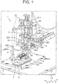
- FIG. 1 is a perspective view showing a waterproof plug insertion device 1 according to an embodiment of the present invention.
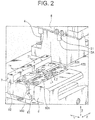
- FIG. 2 is a perspective view showing a main part of the waterproof plug insertion device 1.
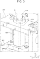
- FIG. 3 is a perspective view showing another main part of the waterproof plug insertion device 1.
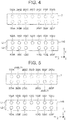
- FIG. 4 is a plan view showing a terminal receiving chamber of a connector housing 100 held by the waterproof plug insertion device 1.
- FIG. 5 is a plan view showing a relationship between the terminal receiving chamber and a pin hole 71 of the waterproof plug insertion device 1.
- the waterproof plug insertion device 1 of the present embodiment is for inserting a waterproof plug into a terminal receiving chamber of the connector housing 100, and includes an emitting device 2, a supply device 3, a pin member 4, an operation unit 5, a holding base 6, a template 7 as a positioning unit, and a connecting device 8.
- the connector housing 100 constitutes, for example, a waterproof connector for connecting a battery mounted on a vehicle and an electrical component.
- an insertion direction (emitting direction) of the waterproof plug is Z direction, and the two directions substantially orthogonal to the Z direction are X direction and Y direction.
- the waterproof plug insertion device 1 is used so that the Z direction substantially coincides with the vertical direction and an XY plane substantially coincides with the horizontal plane.
- the emitting device 2 has a cylindrical nozzle member 21 fixed to an upper plate 811 of the connecting device 8 to be described later and extending along the Z direction.
- the nozzle member 21 is constituted by an upper large diameter portion 211 and a lower small diameter portion 212, and an opening at the lower end of the small diameter portion 212 is an exit aperture 2A.
- the small diameter portion 212 can be attached to and detached from the large diameter portion 211, and for example, when the small diameter portion 212 is damaged, only the small diameter portion 212 can be exchanged.
- the waterproof plug is emitted from the exit aperture 2A.
- the supply device 3 supplies a waterproof plug to the upper part of the nozzle member 21 of the emitting device 2.
- a plurality of waterproof plugs is connected in series to form a continuous body, and this continuous body is received in a tube communicating with the nozzle member 21.
- the supply means 3 cuts the continuous body into one waterproof plug and pressurizes the interior of the tube with a compressor so that the waterproof plug is supplied into the nozzle member 21.
- the compressor for emitting the waterproof plug from the exit aperture 2A and the compressor for supplying the waterproof plug to the emitting device 2 may be common or may be independent from each other.
- the pin member 4 is fixed to a later-described lower plate 825 of the connecting device 8 and projects from the lower surface of the lower plate 825 and extends along the Z direction.
- the pin member 4 is connected to the nozzle member 21 of the emitting device 2 by the connecting device 8, thereby configured to move integrally with the nozzle member 21 in the XY plane.
- the pin member 4 and the exit aperture 2A move in conjunction with each other on the XY plane.
- the operation unit 5 is a bar-shaped handle fixed to a later-described side plate 821 of the connecting device 8 and extending along the Y direction.
- the lower unit 82, which will be described later, of the connection device 8 moves three-dimensionally in parallel.
- the holding base 6 is placed on a plate-like base 9, and has a housing holding portion 61 for holding the connector housing 100 and a disposing portion 62 on which the template 7 is disposed. Since the housing holding portion 61 and the disposing portion 62 are aligned in the Y direction, the held connector housing 100 and the template 7 are aligned in the Y direction.
- the housing holding portion 61 holds the two connector housings 100 by sandwiching the two connector housings 100 from the Y direction while aligning the two connector housings 100 in the X direction.
- a plurality of terminal receiving chamber forming surfaces 101 is directed upward in the Z direction (toward the connecting device 8).
- the connector housing 100 has two rows of receiving chamber rows L 1, L 2 in which the terminal receiving chambers are arranged.
- the receiving chamber rows L1 and L2 extend along the X direction, respectively, and the receiving chamber rows L1 and L2 are aligned in the Y direction.
- the connector housing 100 has a rectangular shape when viewed from the Z direction, and the connector housing 100 is held such that a long side direction substantially coincides with the X direction and a short side direction substantially coincides with the Y direction.
- the template 7 is a metal member formed in a band plate shape whose longitudinal direction is the X direction.
- the same number (namely, two) of templates 7 as the connector housings 100 held by the housing holding portion are arranged in the disposing portion 62.
- one template may be provided corresponding to the plurality of connector housings 100, or a plurality of templates may correspond to one connector housing 100.
- the template 7 has fixing portions at both ends in the X direction, so that the template 7 is fixed to the holding base 6 with bolts or the like. That is, the template 7 is formed separately from the holding base 6 and is detachable from the holding base 6.
- a pin hole 71 into which the pin member 4 is inserted is formed on an upper surface of the template 7. This pin hole 71 functions as a fitted portion to be fitted with the pin member 4 as a fitting portion.
- the connecting device 8 includes an upper unit 81 and a lower unit 82 which are capable of moving toward and away from each other in the Z direction and interlocked within the XY plane.
- the connecting device 8 is supported by two support posts 10 standing from the base 9 and extending along the Z direction.
- the upper unit 81 has an upper plate 811 extending along the XY plane.
- the lower unit 82 includes: a pair of side plates 821, 822 extending along the ZX plane and spaced apart in the Y direction; a pair of intermediate plates 823, 824 extending along the XY plane and spaced apart in the Z direction; and a lower plate 825 extending along the XY plane and disposed below the intermediate plates 823, 824.
- the pair of intermediate plates 823, 824 and the lower plate 825 are sandwiched by the pair of side plates 821, 822.
- a guide cylinder 826 extending along the Z direction is provided between the pair of intermediate plates 823, 824.
- the nozzle member 21 is inserted through the guide cylinder 826 and the large diameter portion 211 is guided by the guide cylinder 826 so that the nozzle member 21 moves along the Z direction.
- both the upper unit 81 and the lower unit 82 move. That is, the nozzle member 21 fixed to the upper unit 81 and the pin member 4 fixed to the lower unit 82 are interlocked in the XY plane. At this time, in the XY plane, the moving distance of the operating unit 5, the moving distance of the pin member 4, and the moving distance of the nozzle member 21 are equal to each other.
- the waterproof plug insertion device 1 is equipped with a driving device for moving the upper unit 81 in the Z direction.
- a predetermined operation for example, stepping on a pedal
- the upper unit 81 moves in the Z direction
- the nozzle member 21 also moves in the Z direction.
- the receiving chamber row L1 of the connector housing 100 is constituted by seven terminal receiving chambers 102A to 102G, and the receiving chamber row L2 is constituted by six terminal receiving chambers 103A to 103F.
- the three terminal receiving chambers 103A to 103C and the three terminal receiving chambers 103D to 103F are spaced apart by one terminal receiving chamber.
- the terminal receiving chambers 102A to 102G constituting the receiving chamber row L1 are moved in parallel in the Y direction by a predetermined distance as virtual receiving chambers 202A to 202G, and the terminal receiving chambers 103A to 103F constituting the receiving chamber row L2 are moved in parallel in the Y direction by the same predetermined distance as virtual receiving chambers 203A to 203F.
- the pin hole 71 formed in the template 7 is formed at a position overlapping with any of the virtual receiving chambers 202A to 202G, 203A to 203F.
- the pin hole 71 is arranged at a position overlapping with the virtual receiving chambers 202A to 202G, 203A to 203F in which the plurality of terminal receiving chambers 102A to 102G, 103A to 103F are translated in parallel in the XY plane in a state where the connector housing 100 is held by the holding base 6.
- pin holes 71 are formed at positions overlapping the virtual receiving chambers 202B and 203E, respectively. That is, among the plurality of terminal receiving chambers 102A to 102G, 103A to 103F, the terminal receiving chambers 102B and 103E become target receiving chambers, and the waterproof plugs are inserted.
- the positions and the number of the pin holes formed in the template 7 may be appropriately set according to which terminal receiving chamber becomes the target receiving chamber.
- the operator performs an operation according to the following procedure, whereby the waterproof plug is inserted into the target receiving chamber of the connector housing 100 (that is, the connector housing with the waterproof plug is manufactured).
- the operator holds the connector housing 100 on the holding base 6.
- the template 7 may be exchanged.
- the operator aligns the pin member 4 with the pin hole 71 in the XY plane by operating the operation unit 5 (operation process). At this time, when the tip of the pin member 4 is far from the pin hole 71 in the Z direction, the pin member 4 may be brought close to the pin hole 71.
- the operator lowers the operation unit 5 to lower the pin member 4 and insert the pin member 4 into the pin hole 71.
- the exit aperture 2A is aligned with the target receiving chamber.
- the operator lowers the nozzle member 21 by the driving device and brings it close to the terminal receiving chamber (target receiving chamber).
- the exit aperture 2A may contact the connector housing 100 or may not contact the connector housing 100.
- the operator causes the waterproof plug to be emitted from the exit aperture 2A by the compressor (emission step), and to be inserted into the terminal receiving chamber.
- the operation for lowering the nozzle member 21 and the operation for emitting the waterproof plug may be independent, or may be one operation.
- the pin member 4 and the exit aperture 2A move together, and the template 7 has the pin hole 71 at a position corresponding to the target receiving chamber. Therefore, when the pin member 4 and the pin hole 71 are fitted together, the exit aperture 2A is aligned with the target receiving chamber. Accordingly, the operator can insert the waterproof plug into the target receiving chamber by causing the emitting device 2 to emit the waterproof plug the in a state where the pin member 4 and the pin hole 71 are fitted together. In this way, when inserting the waterproof plug into the terminal receiving chamber of the connector housing 100, the operator does not need to align the exit aperture 2A with the terminal receiving chamber, so that workability can be improved.
- the template 7 has the pin hole 71 at the position corresponding to the target receiving chamber, the operator does not need to select the target receiving chamber from the plurality of terminal receiving chambers. Therefore, it is possible to suppress the erroneous insertion of the waterproof plug into the terminal receiving chamber to receive a terminal fitting.
- the pin hole 71 is disposed at a position overlapping the virtual receiving chamber, it is possible to easily manufacture the template 7 according to the target receiving chamber. Further, the operator can easily confirm which terminal receiving chamber is set as the target receiving chamber based on an arrangement of the pin hole 71.
- the template 7 is attachable to and detachable from the holding base 6, it is possible to cope with by changing the template 7 when the terminal receiving chamber as the target receiving chamber is changed.
- the pin member 4 and the exit aperture 2A can be disposed close to each other, and it is easy to view the pin member 4 and the exit aperture 2A at the same time, so that workability can be improved.
- the present invention is not limited to the above-described embodiment, but includes other configurations and the like that can achieve the object of the present invention, and the following modifications and the like are also included in the present invention.
- the connector housing 100 and the template 7 are arranged in the Y direction which is the short side direction of the connector housing 100.
- the connector housing 100 and the template 7 may be arranged in other directions (for example, the X direction which is the long side direction of the connector housing 100), and the arrangement of the connector housing 100 may be set appropriately according to space efficiency, workability, and the like.
- the template 7 as the positioning unit is formed separately from the holding base 6 and is attachable and detachable.
- the positioning unit may be fixed to the holding base and may not be attachable and detachable.
- the positioning unit may be formed integrally with the holding base. That is, the fitted portion such as a pin hole may be formed on the holding base, and a region where the fitted portion is formed may be used as the positioning unit.
- the pin member can be inserted into only the predetermined pin hole. That is, a pin hole may be formed in all the positions of the template overlapping with the virtual receiving chamber, and a cover member may be used which opens the pin hole corresponding to the target receiving chamber and covers the other pin holes.
- the pin member 4 functions as a fitting portion and the pin hole 71 functions as a fitted portion, that is, the fitting portion is a convex portion and the fitted portion is a concave portion.
- the fitting portion may be a concave portion and the fitted portion may be a convex portion.
- the shapes of the fitting portion and the fitted portion are not limited to concavity and convexity, and may be any shape as long as the operator can recognize that they are fitted with each other.
- the operating unit 5, the pin member 4, and the nozzle member 21 are connected by the connecting device 8, and in the XY plane, the moving distance of the operating unit 5, the moving distance of the pin member 4, and the moving distance of the nozzle member 21 are equal to each other.
- the moving distance of the pin member 4 and the nozzle member 21 may be different from each other, and may be different from the moving distance of the operating unit 5.
- the moving distance of the pin member 4 may be obtained by multiplying the moving distance of the nozzle member 21 by a predetermined coefficient (1 or more). In this case, the pin hole 71 is not disposed at a position overlapping with the virtual receiving chamber.
Landscapes
- Engineering & Computer Science (AREA)
- Manufacturing & Machinery (AREA)
- Manufacturing Of Electrical Connectors (AREA)
- Connector Housings Or Holding Contact Members (AREA)
Abstract
Description
- The present invention relates to a waterproof plug insertion device for inserting a waterproof plug into a terminal receiving chamber of a connector housing and a method for manufacturing a connector housing with a waterproof plug.
- In general, a plurality of terminal receiving chambers is formed in the connector housing, but terminals may not be received in some of the terminal receiving chambers in some cases. In the waterproof connector, when there is an empty receiving chamber that does not receive the terminal, water may pass through the empty receiving chamber and the waterproof property may not be ensured. Therefore, a waterproof plug pushing device for inserting a waterproof plug into a cavity (terminal receiving chamber) of a connector has been proposed (see, for example, Patent Literature 1). In the waterproof plug pushing device described in
Patent Literature 1, by providing a pressurizing mechanism for pushing out the waterproof plug, the workability when mounting the waterproof plug in the cavity is improved. - Patent Literature 1:
JP 2002-324620 A - However, in the waterproof plug pushing device described in
Patent Literature 1, an operator must select a cavity to which the waterproof plug is to be attached and align the tip of the device with respect to this cavity. Therefore, further improvement in workability has been desired. - An object of the present invention is to provide a waterproof plug insertion device and a method for manufacturing a connector housing with a waterproof plug, which can improve workability when a waterproof plug is inserted into a terminal receiving chamber of a connector housing.
- According to the present invention, there is provided a waterproof plug insertion device for inserting a waterproof plug into a target receiving chamber of a plurality of terminal receiving chambers in a connector housing, the waterproof plug insertion device comprising:
- an emitting device for emitting the waterproof plug from an exit aperture;
- a supply device for supplying the waterproof plug to the emitting device;
- a fitting portion interlocking with the exit aperture in an intersecting plane intersecting an emitting direction of the waterproof plug;
- an operation unit for moving the emitting device and the fitting portion;
- a holding base for holding the connector housing; and
- a positioning unit provided on the holding base,
- wherein the positioning unit has a fitted portion that can be fitted with the fitting portion at a position corresponding to the target housing chamber.
- According to the waterproof plug insertion device of the present invention, the fitting portion and the exit aperture are interlocked within the plane intersecting the emitting direction, and the positioning unit has the fitted portion at a position corresponding to the object receiving chamber. Thereby, when the fitting portion and the fitted portion are fitted together, the exit aperture is aligned with the target receiving chamber. Therefore, the operator can insert the waterproof plug into the target receiving chamber by causing the emitting device to emit the waterproof plug in a state where the fitting portion and the fitted portion are fitted together. In this way, when inserting the waterproof plug into the terminal receiving chamber of the connector housing, the operator does not need to align the exit aperture with the terminal receiving chamber, so that workability can be improved.
-
-
FIG. 1 is a perspective view showing a waterproof plug insertion device according to an embodiment of the present invention; -
FIG. 2 is a perspective view showing a main part of the waterproof plug insertion device; -
FIG. 3 is a perspective view showing another main part of the waterproof plug insertion device; -
FIG. 4 is a plan view showing a terminal receiving chamber of a connector housing held by the waterproof plug insertion device; and -
FIG. 5 is a plan view showing a relationship between the terminal receiving chamber and a fitted portion of the waterproof plug insertion device. - Hereinafter, embodiments of the present invention will be described with reference to the drawings.
FIG. 1 is a perspective view showing a waterproofplug insertion device 1 according to an embodiment of the present invention.FIG. 2 is a perspective view showing a main part of the waterproofplug insertion device 1.FIG. 3 is a perspective view showing another main part of the waterproofplug insertion device 1.FIG. 4 is a plan view showing a terminal receiving chamber of aconnector housing 100 held by the waterproofplug insertion device 1.FIG. 5 is a plan view showing a relationship between the terminal receiving chamber and apin hole 71 of the waterproofplug insertion device 1. - As shown in
FIG. 1 , the waterproofplug insertion device 1 of the present embodiment is for inserting a waterproof plug into a terminal receiving chamber of theconnector housing 100, and includes anemitting device 2, asupply device 3, apin member 4, anoperation unit 5, aholding base 6, atemplate 7 as a positioning unit, and aconnecting device 8. The connector housing 100 constitutes, for example, a waterproof connector for connecting a battery mounted on a vehicle and an electrical component. In the present embodiment, an insertion direction (emitting direction) of the waterproof plug is Z direction, and the two directions substantially orthogonal to the Z direction are X direction and Y direction. Further, the waterproofplug insertion device 1 is used so that the Z direction substantially coincides with the vertical direction and an XY plane substantially coincides with the horizontal plane. - As shown in
FIGS. 2 and3 , theemitting device 2 has acylindrical nozzle member 21 fixed to anupper plate 811 of the connectingdevice 8 to be described later and extending along the Z direction. Thenozzle member 21 is constituted by an upperlarge diameter portion 211 and a lowersmall diameter portion 212, and an opening at the lower end of thesmall diameter portion 212 is anexit aperture 2A. Thesmall diameter portion 212 can be attached to and detached from thelarge diameter portion 211, and for example, when thesmall diameter portion 212 is damaged, only thesmall diameter portion 212 can be exchanged. By pressurizing an inside of thenozzle member 21 with a compressor, the waterproof plug is emitted from theexit aperture 2A. - The
supply device 3 supplies a waterproof plug to the upper part of thenozzle member 21 of theemitting device 2. In the present embodiment, a plurality of waterproof plugs is connected in series to form a continuous body, and this continuous body is received in a tube communicating with thenozzle member 21. The supply means 3 cuts the continuous body into one waterproof plug and pressurizes the interior of the tube with a compressor so that the waterproof plug is supplied into thenozzle member 21. Incidentally, the compressor for emitting the waterproof plug from theexit aperture 2A and the compressor for supplying the waterproof plug to theemitting device 2 may be common or may be independent from each other. - The
pin member 4 is fixed to a later-describedlower plate 825 of the connectingdevice 8 and projects from the lower surface of thelower plate 825 and extends along the Z direction. Thepin member 4 is connected to thenozzle member 21 of theemitting device 2 by the connectingdevice 8, thereby configured to move integrally with thenozzle member 21 in the XY plane. In other words, thepin member 4 and theexit aperture 2A move in conjunction with each other on the XY plane. - The
operation unit 5 is a bar-shaped handle fixed to a later-describedside plate 821 of theconnecting device 8 and extending along the Y direction. When the operator operates theoperation unit 5, thelower unit 82, which will be described later, of theconnection device 8 moves three-dimensionally in parallel. - The
holding base 6 is placed on a plate-like base 9, and has ahousing holding portion 61 for holding theconnector housing 100 and adisposing portion 62 on which thetemplate 7 is disposed. Since thehousing holding portion 61 and thedisposing portion 62 are aligned in the Y direction, the heldconnector housing 100 and thetemplate 7 are aligned in the Y direction. - The
housing holding portion 61 holds the twoconnector housings 100 by sandwiching the twoconnector housings 100 from the Y direction while aligning the twoconnector housings 100 in the X direction. In theconnector housing 100 held by thehousing holding portion 61, a plurality of terminal receivingchamber forming surfaces 101 is directed upward in the Z direction (toward the connecting device 8). In addition, theconnector housing 100 has two rows of receivingchamber rows L 1,L 2 in which the terminal receiving chambers are arranged. When being held by thehousing holding portion 61, the receiving chamber rows L1 and L2 extend along the X direction, respectively, and the receiving chamber rows L1 and L2 are aligned in the Y direction. Theconnector housing 100 has a rectangular shape when viewed from the Z direction, and theconnector housing 100 is held such that a long side direction substantially coincides with the X direction and a short side direction substantially coincides with the Y direction. - The
template 7 is a metal member formed in a band plate shape whose longitudinal direction is the X direction. In this embodiment, the same number (namely, two) oftemplates 7 as theconnector housings 100 held by the housing holding portion are arranged in the disposingportion 62. Incidentally, one template may be provided corresponding to the plurality ofconnector housings 100, or a plurality of templates may correspond to oneconnector housing 100. - The
template 7 has fixing portions at both ends in the X direction, so that thetemplate 7 is fixed to the holdingbase 6 with bolts or the like. That is, thetemplate 7 is formed separately from the holdingbase 6 and is detachable from the holdingbase 6. Apin hole 71 into which thepin member 4 is inserted is formed on an upper surface of thetemplate 7. Thispin hole 71 functions as a fitted portion to be fitted with thepin member 4 as a fitting portion. - The connecting
device 8 includes anupper unit 81 and alower unit 82 which are capable of moving toward and away from each other in the Z direction and interlocked within the XY plane. The connectingdevice 8 is supported by twosupport posts 10 standing from thebase 9 and extending along the Z direction. Theupper unit 81 has anupper plate 811 extending along the XY plane. - The
lower unit 82 includes: a pair ofside plates intermediate plates lower plate 825 extending along the XY plane and disposed below theintermediate plates intermediate plates lower plate 825 are sandwiched by the pair ofside plates - A
guide cylinder 826 extending along the Z direction is provided between the pair ofintermediate plates nozzle member 21 is inserted through theguide cylinder 826 and thelarge diameter portion 211 is guided by theguide cylinder 826 so that thenozzle member 21 moves along the Z direction. - Since the
operation unit 5 is fixed to thelower unit 82, and theupper unit 81 and thelower unit 82 are interlocked in the XY plane, when the operator operates theoperation unit 5 to move the connectingdevice 8 within the XY plane, both theupper unit 81 and thelower unit 82 move. That is, thenozzle member 21 fixed to theupper unit 81 and thepin member 4 fixed to thelower unit 82 are interlocked in the XY plane. At this time, in the XY plane, the moving distance of theoperating unit 5, the moving distance of thepin member 4, and the moving distance of thenozzle member 21 are equal to each other. - Since the
operation unit 5 is fixed to thelower unit 82, and theupper unit 81 and thelower unit 82 can be attached to and detached from each other in the Z direction, when the operator operates theoperation unit 5 to move the connectingunit 8 in the Z Direction, only thelower unit 82 moves. That is, thenozzle member 21 fixed to theupper unit 81 and thepin member 4 fixed to thelower unit 82 are not interlocked with each other in the Z direction. The waterproofplug insertion device 1 is equipped with a driving device for moving theupper unit 81 in the Z direction. When the operator performs a predetermined operation (for example, stepping on a pedal), theupper unit 81 moves in the Z direction, and accordingly thenozzle member 21 also moves in the Z direction. - Here, details of the
pin hole 71 formed in thetemplate 7 will be described with reference toFIGS. 4 and 5 . In the present embodiment, the receiving chamber row L1 of theconnector housing 100 is constituted by seventerminal receiving chambers 102A to 102G, and the receiving chamber row L2 is constituted by sixterminal receiving chambers 103A to 103F. The threeterminal receiving chambers 103A to 103C and the threeterminal receiving chambers 103D to 103F are spaced apart by one terminal receiving chamber. - The
terminal receiving chambers 102A to 102G constituting the receiving chamber row L1 are moved in parallel in the Y direction by a predetermined distance asvirtual receiving chambers 202A to 202G, and theterminal receiving chambers 103A to 103F constituting the receiving chamber row L2 are moved in parallel in the Y direction by the same predetermined distance asvirtual receiving chambers 203A to 203F. Thepin hole 71 formed in thetemplate 7 is formed at a position overlapping with any of thevirtual receiving chambers 202A to 202G, 203A to 203F. That is, thepin hole 71 is arranged at a position overlapping with thevirtual receiving chambers 202A to 202G, 203A to 203F in which the plurality ofterminal receiving chambers 102A to 102G, 103A to 103F are translated in parallel in the XY plane in a state where theconnector housing 100 is held by the holdingbase 6. - In the example shown in
FIG. 5 , in thetemplate 7, pin holes 71 are formed at positions overlapping thevirtual receiving chambers terminal receiving chambers 102A to 102G, 103A to 103F, theterminal receiving chambers template 7 may be appropriately set according to which terminal receiving chamber becomes the target receiving chamber. - In the waterproof
plug insertion device 1 as described above, the operator performs an operation according to the following procedure, whereby the waterproof plug is inserted into the target receiving chamber of the connector housing 100 (that is, the connector housing with the waterproof plug is manufactured). First, the operator holds theconnector housing 100 on the holdingbase 6. Incidentally, when the target receiving chamber is changed, thetemplate 7 may be exchanged. Next, the operator aligns thepin member 4 with thepin hole 71 in the XY plane by operating the operation unit 5 (operation process). At this time, when the tip of thepin member 4 is far from thepin hole 71 in the Z direction, thepin member 4 may be brought close to thepin hole 71. - When the
pin member 4 and thepin hole 71 are aligned with each other, the operator lowers theoperation unit 5 to lower thepin member 4 and insert thepin member 4 into thepin hole 71. As a result, theexit aperture 2A is aligned with the target receiving chamber. Next, the operator lowers thenozzle member 21 by the driving device and brings it close to the terminal receiving chamber (target receiving chamber). At this time, theexit aperture 2A may contact theconnector housing 100 or may not contact theconnector housing 100, Next, the operator causes the waterproof plug to be emitted from theexit aperture 2A by the compressor (emission step), and to be inserted into the terminal receiving chamber. Incidentally, the operation for lowering thenozzle member 21 and the operation for emitting the waterproof plug may be independent, or may be one operation. - In a case where a plurality of target receiving chambers are set in the
connector housing 100, after the waterproof plug is inserted, thepin member 4 and thenozzle member 21 are raised, and then by repeating the above operation, the waterproof plugs are inserted into all the target receiving chambers. - According to the embodiment described above, there is the following effect. That is, in the XY plane, the
pin member 4 and theexit aperture 2A move together, and thetemplate 7 has thepin hole 71 at a position corresponding to the target receiving chamber. Therefore, when thepin member 4 and thepin hole 71 are fitted together, theexit aperture 2A is aligned with the target receiving chamber. Accordingly, the operator can insert the waterproof plug into the target receiving chamber by causing the emittingdevice 2 to emit the waterproof plug the in a state where thepin member 4 and thepin hole 71 are fitted together. In this way, when inserting the waterproof plug into the terminal receiving chamber of theconnector housing 100, the operator does not need to align theexit aperture 2A with the terminal receiving chamber, so that workability can be improved. - In addition, since the
template 7 has thepin hole 71 at the position corresponding to the target receiving chamber, the operator does not need to select the target receiving chamber from the plurality of terminal receiving chambers. Therefore, it is possible to suppress the erroneous insertion of the waterproof plug into the terminal receiving chamber to receive a terminal fitting. - Further, since the
pin hole 71 is disposed at a position overlapping the virtual receiving chamber, it is possible to easily manufacture thetemplate 7 according to the target receiving chamber. Further, the operator can easily confirm which terminal receiving chamber is set as the target receiving chamber based on an arrangement of thepin hole 71. - Further, since the
template 7 is attachable to and detachable from the holdingbase 6, it is possible to cope with by changing thetemplate 7 when the terminal receiving chamber as the target receiving chamber is changed. - In addition, since the
connector housing 100 and thetemplate 7 are arranged in the Y direction which is the short side direction of theconnector housing 100, thepin member 4 and theexit aperture 2A can be disposed close to each other, and it is easy to view thepin member 4 and theexit aperture 2A at the same time, so that workability can be improved. - Incidentally, the present invention is not limited to the above-described embodiment, but includes other configurations and the like that can achieve the object of the present invention, and the following modifications and the like are also included in the present invention.
- For example, in the above embodiment, the
connector housing 100 and thetemplate 7 are arranged in the Y direction which is the short side direction of theconnector housing 100. However, theconnector housing 100 and thetemplate 7 may be arranged in other directions (for example, the X direction which is the long side direction of the connector housing 100), and the arrangement of theconnector housing 100 may be set appropriately according to space efficiency, workability, and the like. - Further, in the above-described embodiment, the
template 7 as the positioning unit is formed separately from the holdingbase 6 and is attachable and detachable. However, the positioning unit may be fixed to the holding base and may not be attachable and detachable. Further, the positioning unit may be formed integrally with the holding base. That is, the fitted portion such as a pin hole may be formed on the holding base, and a region where the fitted portion is formed may be used as the positioning unit. - Further, by covering the template having the pin holes formed therein with a cover member, the pin member can be inserted into only the predetermined pin hole. That is, a pin hole may be formed in all the positions of the template overlapping with the virtual receiving chamber, and a cover member may be used which opens the pin hole corresponding to the target receiving chamber and covers the other pin holes.
- Further, in the above-described embodiment, the
pin member 4 functions as a fitting portion and thepin hole 71 functions as a fitted portion, that is, the fitting portion is a convex portion and the fitted portion is a concave portion. However, the fitting portion may be a concave portion and the fitted portion may be a convex portion. Further, the shapes of the fitting portion and the fitted portion are not limited to concavity and convexity, and may be any shape as long as the operator can recognize that they are fitted with each other. - In the above embodiment, the
operating unit 5, thepin member 4, and thenozzle member 21 are connected by the connectingdevice 8, and in the XY plane, the moving distance of theoperating unit 5, the moving distance of thepin member 4, and the moving distance of thenozzle member 21 are equal to each other. However, the moving distance of thepin member 4 and thenozzle member 21 may be different from each other, and may be different from the moving distance of theoperating unit 5. For example, in the case where the space between the terminal receiving chambers in thehousing 100 is narrow, the moving distance of thepin member 4 may be obtained by multiplying the moving distance of thenozzle member 21 by a predetermined coefficient (1 or more). In this case, thepin hole 71 is not disposed at a position overlapping with the virtual receiving chamber. - Although the best configurations, methods, and the like for carrying out the present invention are disclosed in the above description, the present invention is not limited thereto. While the invention has been particularly shown and described with particular reference to certain embodiments thereof, material, quantity, and other detailed configurations, various modifications can be made by those skilled in the art without departing from the spirit and scope of the invention. Accordingly, the description that limits the shape, material, etc. disclosed above is exemplarily described for easy understanding of the present invention, and does not limit the present invention, so the description of the parts with limitations on part or all of the restrictions on their shapes, materials and the like is included in the present invention.
-
- 1 waterproof plug insertion device
- 2 emitting device
- 2A exit aperture
- 3 supply device
- 4 pin member (fitting portion)
- 5 operation unit
- 6 holding base
- 7 template (positioning unit)
- 71 pin hole (fitted portion)
- 100 connector housing
- 102A - 102G, 103A - 103F terminal receiving chamber
- 202A - 202G, 203A - 203F virtual receiving chamber
Claims (5)
- A waterproof plug insertion device for inserting a waterproof plug into a target receiving chamber of a plurality of terminal receiving chambers in a connector housing, the waterproof plug insertion device comprising:an emitting device for emitting the waterproof plug from an exit aperture;a supply device for supplying the waterproof plug to the emitting device;a fitting portion interlocking with the exit aperture in an intersecting plane intersecting an emitting direction of the waterproof plug;an operation unit for moving the emitting device and the fitting portion;a holding base for holding the connector housing; anda positioning unit provided on the holding base,wherein the positioning unit has a fitted portion that can be fitted with the fitting portion at a position corresponding to the target housing chamber.
- The waterproof plug insertion device as claimed in claim 1,
wherein the fitted portion is disposed at a position overlapping a virtual receiving chamber in which the plurality of terminal receiving chambers is moved in parallel in the intersecting plane in a state where the connector housing is held by the holding base. - The waterproof plug insertion device as claimed in claim 1 or 2,
wherein the positioning unit is formed separately from the holding base and is detachable. - The waterproof plug insertion device as claimed in any one of claims 1 to 3,
wherein the holding base holds the connector housing so as to be aligned with the positioning unit in a short side direction of the connector housing. - A producing method of a connector housing with a waterproof plug for producing the connector housing in which the waterproof plug is inserted into a target receiving chamber among a plurality of terminal receiving chambers in the connector housing, the method comprising the steps of:interlocking a fitting portion with an exit aperture in an intersecting plane intersecting an emitting direction of the waterproof plug;emitting the waterproof plug from the exit aperture while the fitting portion and a fitted portion are fitted to each other, the fitted portion being provided on a holding base for holding the connector housing and being disposed at a position corresponding to the target receiving chamber.
Applications Claiming Priority (1)
| Application Number | Priority Date | Filing Date | Title |
|---|---|---|---|
| JP2018119871A JP6732846B2 (en) | 2018-06-25 | 2018-06-25 | Waterproof plug insertion device and method for manufacturing connector housing with waterproof plug |
Publications (1)
| Publication Number | Publication Date |
|---|---|
| EP3588697A1 true EP3588697A1 (en) | 2020-01-01 |
Family
ID=66217894
Family Applications (1)
| Application Number | Title | Priority Date | Filing Date |
|---|---|---|---|
| EP19169762.2A Withdrawn EP3588697A1 (en) | 2018-06-25 | 2019-04-17 | Waterproof plug insertion device and connector housing manufacturing method with waterproof plug |
Country Status (4)
| Country | Link |
|---|---|
| US (1) | US20190393641A1 (en) |
| EP (1) | EP3588697A1 (en) |
| JP (1) | JP6732846B2 (en) |
| CN (1) | CN110635335A (en) |
Families Citing this family (3)
| Publication number | Priority date | Publication date | Assignee | Title |
|---|---|---|---|---|
| JP7409999B2 (en) * | 2020-08-31 | 2024-01-09 | 矢崎総業株式会社 | Waterproof plug insertion device |
| CN218490786U (en) * | 2022-10-18 | 2023-02-17 | 深圳市林全科技有限公司 | Wire rain plug penetrating device |
| CN117154484B (en) * | 2023-08-31 | 2025-07-18 | 杭州航天电子技术有限公司 | Automatic device for automatic assembly of clamp ring |
Citations (2)
| Publication number | Priority date | Publication date | Assignee | Title |
|---|---|---|---|---|
| JP2002324620A (en) | 2001-04-27 | 2002-11-08 | Sumitomo Wiring Syst Ltd | Waterproof stopper push-in device |
| JP2008010365A (en) * | 2006-06-30 | 2008-01-17 | Yazaki Corp | Waterproof plug press-fitting device for sealing |
Family Cites Families (5)
| Publication number | Priority date | Publication date | Assignee | Title |
|---|---|---|---|---|
| JP3018883B2 (en) * | 1993-12-28 | 2000-03-13 | 住友電装株式会社 | Waterproof stopper supply device |
| JP3109423B2 (en) * | 1995-10-05 | 2000-11-13 | 住友電装株式会社 | Rubber stopper attachment |
| JPH09290332A (en) * | 1996-03-01 | 1997-11-11 | Yazaki Corp | Rubber stopper inserting device, rubber stopper supplying method, and rubber stopper inserting method |
| US6929509B2 (en) * | 2002-03-21 | 2005-08-16 | Komax Holding Ag | Method and device for sealing off channels of electric connectors |
| JP2008167592A (en) * | 2006-12-28 | 2008-07-17 | Tyco Electronics Amp Kk | Seal member mounting device |
-
2018
- 2018-06-25 JP JP2018119871A patent/JP6732846B2/en active Active
-
2019
- 2019-04-05 US US16/376,041 patent/US20190393641A1/en not_active Abandoned
- 2019-04-17 EP EP19169762.2A patent/EP3588697A1/en not_active Withdrawn
- 2019-06-20 CN CN201910538603.XA patent/CN110635335A/en not_active Withdrawn
Patent Citations (2)
| Publication number | Priority date | Publication date | Assignee | Title |
|---|---|---|---|---|
| JP2002324620A (en) | 2001-04-27 | 2002-11-08 | Sumitomo Wiring Syst Ltd | Waterproof stopper push-in device |
| JP2008010365A (en) * | 2006-06-30 | 2008-01-17 | Yazaki Corp | Waterproof plug press-fitting device for sealing |
Also Published As
| Publication number | Publication date |
|---|---|
| JP2020004498A (en) | 2020-01-09 |
| CN110635335A (en) | 2019-12-31 |
| JP6732846B2 (en) | 2020-07-29 |
| US20190393641A1 (en) | 2019-12-26 |
Similar Documents
| Publication | Publication Date | Title |
|---|---|---|
| US20190393641A1 (en) | Waterproof plug insertion device and connector housing manufacturing method with waterproof plug | |
| US8426056B2 (en) | Power supply device | |
| KR102203830B1 (en) | Battery pack having tray of bottom connection type and manufacturing method thereof | |
| CN102509982A (en) | Connector assembly having a connector extender module | |
| US20140283360A1 (en) | Battery holder and manufacturing method of battery holder | |
| JP2017521821A (en) | Electrical connector with terminal holder | |
| CN111448715B (en) | Terminal holder, wire harness, and fixing structure | |
| EP2966774A1 (en) | Terminal box | |
| US20120043986A1 (en) | Junction box with test contact | |
| JP2019121474A (en) | Connection module | |
| JP5268241B2 (en) | Pack battery and manufacturing method thereof | |
| KR102280995B1 (en) | Battery module comprising housing with connector | |
| JP6278311B2 (en) | Light emitting module and lighting apparatus using the same | |
| US11424568B2 (en) | Electric connector having shielding plate, and manufacturing method for housing of electric connector | |
| WO2023210207A1 (en) | Voltage detection device and battery module | |
| US10948072B2 (en) | Control circuit device for automatic transmission | |
| JP6804926B2 (en) | Electronic component module | |
| KR102165739B1 (en) | Hold down of connector and connector including the same | |
| KR102917134B1 (en) | Method for manufacturing battery module | |
| KR20220141745A (en) | Electrical connector and electrical connector assembly | |
| KR102227357B1 (en) | battery charging device for charging type power tool | |
| CN208614181U (en) | Unhook cover board reed assembled fixture is protected after one kind | |
| EP3343101A1 (en) | Lighting device for a vehicle and related attachment method | |
| CN115588872B (en) | Connector device | |
| EP4109679A1 (en) | Connector device |
Legal Events
| Date | Code | Title | Description |
|---|---|---|---|
| PUAI | Public reference made under article 153(3) epc to a published international application that has entered the european phase |
Free format text: ORIGINAL CODE: 0009012 |
|
| 17P | Request for examination filed |
Effective date: 20190417 |
|
| AK | Designated contracting states |
Kind code of ref document: A1 Designated state(s): AL AT BE BG CH CY CZ DE DK EE ES FI FR GB GR HR HU IE IS IT LI LT LU LV MC MK MT NL NO PL PT RO RS SE SI SK SM TR |
|
| AX | Request for extension of the european patent |
Extension state: BA ME |
|
| RBV | Designated contracting states (corrected) |
Designated state(s): AL AT BE BG CH CY CZ DE DK EE ES FI FR GB GR HR HU IE IS IT LI LT LU LV MC MK MT NL NO PL PT RO RS SE SI SK SM TR |
|
| STAA | Information on the status of an ep patent application or granted ep patent |
Free format text: STATUS: THE APPLICATION HAS BEEN WITHDRAWN |
|
| 18W | Application withdrawn |
Effective date: 20200807 |