EP3588647A1 - Humidifier for fuel cell - Google Patents
Humidifier for fuel cell Download PDFInfo
- Publication number
- EP3588647A1 EP3588647A1 EP18778184.4A EP18778184A EP3588647A1 EP 3588647 A1 EP3588647 A1 EP 3588647A1 EP 18778184 A EP18778184 A EP 18778184A EP 3588647 A1 EP3588647 A1 EP 3588647A1
- Authority
- EP
- European Patent Office
- Prior art keywords
- fuel cell
- housing
- cap
- interior space
- bypass tube
- Prior art date
- Legal status (The legal status is an assumption and is not a legal conclusion. Google has not performed a legal analysis and makes no representation as to the accuracy of the status listed.)
- Pending
Links
- 239000000446 fuel Substances 0.000 title claims abstract description 79
- XLYOFNOQVPJJNP-UHFFFAOYSA-N water Substances O XLYOFNOQVPJJNP-UHFFFAOYSA-N 0.000 claims abstract description 63
- 239000012528 membrane Substances 0.000 claims abstract description 50
- 239000012510 hollow fiber Substances 0.000 claims abstract description 45
- 238000004891 communication Methods 0.000 claims abstract description 7
- 239000012530 fluid Substances 0.000 claims abstract description 7
- 238000007599 discharging Methods 0.000 claims description 3
- 239000007789 gas Substances 0.000 description 38
- 239000001257 hydrogen Substances 0.000 description 9
- 229910052739 hydrogen Inorganic materials 0.000 description 9
- 238000010248 power generation Methods 0.000 description 7
- 239000007788 liquid Substances 0.000 description 6
- 238000010586 diagram Methods 0.000 description 5
- -1 hydrogen ions Chemical class 0.000 description 5
- 239000005518 polymer electrolyte Substances 0.000 description 5
- 230000005494 condensation Effects 0.000 description 4
- 238000009833 condensation Methods 0.000 description 4
- UFHFLCQGNIYNRP-UHFFFAOYSA-N Hydrogen Chemical compound [H][H] UFHFLCQGNIYNRP-UHFFFAOYSA-N 0.000 description 3
- 230000008014 freezing Effects 0.000 description 3
- 238000007710 freezing Methods 0.000 description 3
- QVGXLLKOCUKJST-UHFFFAOYSA-N atomic oxygen Chemical compound [O] QVGXLLKOCUKJST-UHFFFAOYSA-N 0.000 description 2
- 150000002500 ions Chemical class 0.000 description 2
- 239000001301 oxygen Substances 0.000 description 2
- 229910052760 oxygen Inorganic materials 0.000 description 2
- 230000000903 blocking effect Effects 0.000 description 1
- 239000004020 conductor Substances 0.000 description 1
- 230000005611 electricity Effects 0.000 description 1
- 230000002708 enhancing effect Effects 0.000 description 1
- 230000007717 exclusion Effects 0.000 description 1
- 230000005484 gravity Effects 0.000 description 1
- 150000002431 hydrogen Chemical class 0.000 description 1
- 238000004519 manufacturing process Methods 0.000 description 1
Images

Classifications
-
- H—ELECTRICITY
- H01—ELECTRIC ELEMENTS
- H01M—PROCESSES OR MEANS, e.g. BATTERIES, FOR THE DIRECT CONVERSION OF CHEMICAL ENERGY INTO ELECTRICAL ENERGY
- H01M8/00—Fuel cells; Manufacture thereof
- H01M8/04—Auxiliary arrangements, e.g. for control of pressure or for circulation of fluids
- H01M8/04082—Arrangements for control of reactant parameters, e.g. pressure or concentration
- H01M8/04089—Arrangements for control of reactant parameters, e.g. pressure or concentration of gaseous reactants
- H01M8/04119—Arrangements for control of reactant parameters, e.g. pressure or concentration of gaseous reactants with simultaneous supply or evacuation of electrolyte; Humidifying or dehumidifying
- H01M8/04156—Arrangements for control of reactant parameters, e.g. pressure or concentration of gaseous reactants with simultaneous supply or evacuation of electrolyte; Humidifying or dehumidifying with product water removal
-
- B—PERFORMING OPERATIONS; TRANSPORTING
- B01—PHYSICAL OR CHEMICAL PROCESSES OR APPARATUS IN GENERAL
- B01D—SEPARATION
- B01D63/00—Apparatus in general for separation processes using semi-permeable membranes
- B01D63/02—Hollow fibre modules
- B01D63/031—Two or more types of hollow fibres within one bundle or within one potting or tube-sheet
-
- H—ELECTRICITY
- H01—ELECTRIC ELEMENTS
- H01M—PROCESSES OR MEANS, e.g. BATTERIES, FOR THE DIRECT CONVERSION OF CHEMICAL ENERGY INTO ELECTRICAL ENERGY
- H01M8/00—Fuel cells; Manufacture thereof
- H01M8/04—Auxiliary arrangements, e.g. for control of pressure or for circulation of fluids
- H01M8/04082—Arrangements for control of reactant parameters, e.g. pressure or concentration
- H01M8/04089—Arrangements for control of reactant parameters, e.g. pressure or concentration of gaseous reactants
- H01M8/04119—Arrangements for control of reactant parameters, e.g. pressure or concentration of gaseous reactants with simultaneous supply or evacuation of electrolyte; Humidifying or dehumidifying
-
- H—ELECTRICITY
- H01—ELECTRIC ELEMENTS
- H01M—PROCESSES OR MEANS, e.g. BATTERIES, FOR THE DIRECT CONVERSION OF CHEMICAL ENERGY INTO ELECTRICAL ENERGY
- H01M8/00—Fuel cells; Manufacture thereof
- H01M8/04—Auxiliary arrangements, e.g. for control of pressure or for circulation of fluids
- H01M8/04082—Arrangements for control of reactant parameters, e.g. pressure or concentration
- H01M8/04089—Arrangements for control of reactant parameters, e.g. pressure or concentration of gaseous reactants
- H01M8/04119—Arrangements for control of reactant parameters, e.g. pressure or concentration of gaseous reactants with simultaneous supply or evacuation of electrolyte; Humidifying or dehumidifying
- H01M8/04126—Humidifying
- H01M8/04141—Humidifying by water containing exhaust gases
-
- H—ELECTRICITY
- H01—ELECTRIC ELEMENTS
- H01M—PROCESSES OR MEANS, e.g. BATTERIES, FOR THE DIRECT CONVERSION OF CHEMICAL ENERGY INTO ELECTRICAL ENERGY
- H01M8/00—Fuel cells; Manufacture thereof
- H01M8/04—Auxiliary arrangements, e.g. for control of pressure or for circulation of fluids
- H01M8/04082—Arrangements for control of reactant parameters, e.g. pressure or concentration
- H01M8/04089—Arrangements for control of reactant parameters, e.g. pressure or concentration of gaseous reactants
- H01M8/04119—Arrangements for control of reactant parameters, e.g. pressure or concentration of gaseous reactants with simultaneous supply or evacuation of electrolyte; Humidifying or dehumidifying
- H01M8/04126—Humidifying
- H01M8/04149—Humidifying by diffusion, e.g. making use of membranes
-
- B—PERFORMING OPERATIONS; TRANSPORTING
- B01—PHYSICAL OR CHEMICAL PROCESSES OR APPARATUS IN GENERAL
- B01D—SEPARATION
- B01D2313/00—Details relating to membrane modules or apparatus
- B01D2313/08—Flow guidance means within the module or the apparatus
-
- B—PERFORMING OPERATIONS; TRANSPORTING
- B01—PHYSICAL OR CHEMICAL PROCESSES OR APPARATUS IN GENERAL
- B01D—SEPARATION
- B01D2313/00—Details relating to membrane modules or apparatus
- B01D2313/08—Flow guidance means within the module or the apparatus
- B01D2313/083—Bypass routes
-
- B—PERFORMING OPERATIONS; TRANSPORTING
- B01—PHYSICAL OR CHEMICAL PROCESSES OR APPARATUS IN GENERAL
- B01D—SEPARATION
- B01D2313/00—Details relating to membrane modules or apparatus
- B01D2313/20—Specific housing
-
- B—PERFORMING OPERATIONS; TRANSPORTING
- B01—PHYSICAL OR CHEMICAL PROCESSES OR APPARATUS IN GENERAL
- B01D—SEPARATION
- B01D2315/00—Details relating to the membrane module operation
- B01D2315/22—Membrane contactor
-
- B—PERFORMING OPERATIONS; TRANSPORTING
- B01—PHYSICAL OR CHEMICAL PROCESSES OR APPARATUS IN GENERAL
- B01D—SEPARATION
- B01D2315/00—Details relating to the membrane module operation
- B01D2315/24—Counter-current operation
-
- H—ELECTRICITY
- H01—ELECTRIC ELEMENTS
- H01M—PROCESSES OR MEANS, e.g. BATTERIES, FOR THE DIRECT CONVERSION OF CHEMICAL ENERGY INTO ELECTRICAL ENERGY
- H01M8/00—Fuel cells; Manufacture thereof
- H01M8/10—Fuel cells with solid electrolytes
- H01M2008/1095—Fuel cells with polymeric electrolytes
-
- Y—GENERAL TAGGING OF NEW TECHNOLOGICAL DEVELOPMENTS; GENERAL TAGGING OF CROSS-SECTIONAL TECHNOLOGIES SPANNING OVER SEVERAL SECTIONS OF THE IPC; TECHNICAL SUBJECTS COVERED BY FORMER USPC CROSS-REFERENCE ART COLLECTIONS [XRACs] AND DIGESTS
- Y02—TECHNOLOGIES OR APPLICATIONS FOR MITIGATION OR ADAPTATION AGAINST CLIMATE CHANGE
- Y02E—REDUCTION OF GREENHOUSE GAS [GHG] EMISSIONS, RELATED TO ENERGY GENERATION, TRANSMISSION OR DISTRIBUTION
- Y02E60/00—Enabling technologies; Technologies with a potential or indirect contribution to GHG emissions mitigation
- Y02E60/30—Hydrogen technology
- Y02E60/50—Fuel cells
Definitions
- the present disclosure relates to a fuel cell humidifier, more particularly, to the fuel cell humidifier that may completely or substantially completely prevent condensate water from flowing into a running fuel cell stack.
- a fuel cell is a device for generating electricity while producing water by reacting hydrogen, which is a fuel, with oxygen in the air.
- High purity hydrogen is supplied from a hydrogen storage tank to an anode of a fuel cell stack, and air in the atmosphere is supplied to a cathode of the fuel cell stack through an air supply device such as a blower.
- Hydrogen supplied to the anode of the fuel cell stack is separated into hydrogen ions and electrons. Hydrogen ions move to the cathode through a polymer electrolyte membrane between the anode and the cathode, and electrons move to the cathode through an external conductor. Oxygen supplied to the cathode of the fuel cell stack generates electrical energy while combining with electron and hydrogen ions to produce water.
- the hydrogen ions are more easily transferred from the anode to the cathode.
- the ion conductivity of the polymer electrolyte membrane is closely related to water content. That is, as the polymer electrolyte membrane is sufficiently wetted, the hydrogen ions may be better transferred from the anode to the cathode.
- a humidifier which may provide moisture to the air supplied to the cathode of the fuel cell stack, is utilized.
- the fuel cell humidifier humidifies the air supplied from the outside with moisture in an off-gas discharged from the cathode of the stack, and supplies the humidified air to the cathode of the stack.
- Condensate water is inevitably caused in the humidifier as the humidified air contacts the physical structure of the humidifier (e.g., a hollow fiber membrane for humidification, a passage structure through which the humidified air flows, etc.).
- the condensate water flows into the running fuel cell stack, it causes a reduction in the power generation efficiency. Accordingly, it is desirable to take measures to prevent the condensate water from flowing into the running fuel cell stack.
- U.S. Patent No. 7,264,233 discloses a humidifier 1 capable of transferring the condensate water that is stagnant in a liquid pool area 33 inside a downstream head 3 through which humidified air flows to a lead-in manifold 5 through which off-gas flows.
- the humidifier 1 of the '233 patent includes a communicating tube 6 for connecting the liquid pool area 33 where the condensate water is stagnant with the lead-in manifold 5. That is, it is assumed that the condensate water falls down by gravity to be necessarily collected in a lower region (referred to as the "liquid pool area") 33 inside the downstream head 3.
- the present disclosure relates to a fuel cell humidifier capable of preventing problems caused by the above limitations and disadvantages of the related art.
- One aspect of the present disclosure is to provide a fuel cell humidifier capable of completely or substantially completely preventing condensate water from flowing into a running fuel cell stack.
- a fuel cell humidifier for humidifying air supplied from outside with moisture in an off-gas discharged from a fuel cell stack and supplying the humidified air to the fuel cell stack, including a humidification module including a housing and a plurality of hollow fiber membranes arranged in the housing; a first cap having an air discharge port for supplying the humidified air to the fuel cell stack and coupled to a first termination end of the humidification module, the air discharge port being spaced apart from the humidification module; and a bypass tube for transferring the condensate water generated from the humidified air to the interior space of the housing through which the off-gas flows, and a first end of the bypass tube is positioned in the air discharge port, and the bypass tube is in fluid communication with the interior space of the housing through a second end of the bypass tube.
- the fuel cell humidifier may further include a second cap having an air inlet port for receiving the air supplied from the outside and coupled to a second termination end of the humidification module at the opposite side of the first termination end.
- the interior space of the first cap defined by the inner surface of the first cap and the first termination end of the humidification module and the interior space of the second cap defined by the inner surface of the second cap and the second termination end of the humidification module may be in fluid communication with each other only through lumens of the hollow fiber membranes.
- the housing may have an off-gas inlet port for receiving the off-gas from the fuel cell stack and an off-gas outlet port for discharging the off-gas.
- the housing may include a first housing including the hollow fiber membranes and a second housing surrounding the first housing and including the off-gas inlet port and the off-gas outlet port, and the first housing may have a first group of openings corresponding to the off-gas inlet port and a second group of openings corresponding to the off-gas outlet port.
- the hollow fiber membranes may include two or more hollow fiber membrane bundles
- the housing may include two or more first housings including the two or more hollow fiber membrane bundles, respectively; and a second housing surrounding the first housings and having the off-gas inlet port and the off-gas outlet port, and each of the first housings may have a first group of openings corresponding to the off-gas inlet port and a second group of openings corresponding to the off-gas outlet port.
- the condensate water may be generated in the interior space of the first cap or may flow into the interior space of the first cap from the hollow fiber membranes and then may be transferred to the interior space of the housing through the bypass tube.
- the longitudinal direction of the air discharge port and the longitudinal direction of the hollow fiber membranes may not be parallel to each other.
- the first cap may have a rib configured to prevent the condensate water from being transferred to the fuel cell stack through the air discharge port, the rib being disposed in the air discharge port, and a first end of the bypass tube may be positioned adjacent to the rib.
- a screw thread for providing a spiral path to the condensate water may be formed on the inner surface of the air discharge port.
- the first end of the bypass tube may be positioned adjacent to the termination portion of the screw thread, in order to transfer the condensate water, which flows into the air discharge port to reach the termination portion of the screw thread through the spiral path, to the interior space of the housing.
- the bypass tube may include a first tube fixed to the first cap; and a second tube fixed to the humidification module, and the first and second tubes may be detachably coupled.
- the bypass tube may not be exposed to the outside.
- all condensate water generated due to condensation of humidified air that is, not only the condensate water generated in the interior space of the first cap, but also the condensate water generated in the lumen of the hollow fiber membranes to flow into the interior space of the first cap may be transferred to the interior space (i.e., a space where the off-gas flows) of the housing, thereby completely or substantially completely preventing the condensate water from flowing into the running fuel cell stack. Accordingly, a reduction in power generation efficiency due to the condensate water flowing into the fuel cell stack may be prevented.
- the condensate water in the bypass tube may be prevented from being frozen even in a cold environment. Accordingly, the condensate water may be prevented from flowing into the fuel cell stack without bypassing due to the freezing of the condensate water in the bypass tube.
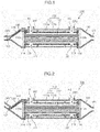
- FIG. 1 is a cross-sectional diagram of a fuel cell humidifier according to a first embodiment of the present disclosure.
- a fuel cell humidifier 100 of the present disclosure is a device for humidifying air supplied from an outside with moisture in off-gas discharged from a fuel cell stack (not shown), and supplying the humidified air to the fuel cell stack.
- the humidifier 100 of the present disclosure includes a humidification module 110 having first and second termination ends 110a, 110b, a first cap 120 having an air discharge port (OP1) for supplying the humidified air to the fuel cell stack and coupled to the first termination end 110a, and a second cap 130 having an air inlet port (IP1) for receiving the air supplied from the outside and coupled to the second termination end 110b.
- a humidification module 110 having first and second termination ends 110a, 110b
- a second cap 130 having an air inlet port (IP1) for receiving the air supplied from the outside and coupled to the second termination end 110b.
- OP1 air discharge port
- IP1 air inlet port
- the air discharge port (OP1) of the first cap 120 and the air inlet port (IP1) of the second cap 130 are spaced apart from the humidification module 110, respectively.
- the humidification module 110 includes a housing 111 and a plurality of hollow fiber membranes 112 disposed in the housing 111.
- the housing 111 has an off-gas inlet port (IP2) for receiving off-gas from a fuel cell stack and an off-gas outlet port (OP2) for discharging the off-gas.
- IP2 off-gas inlet port
- OP2 off-gas outlet port
- the housing 111 includes a first housing 111a including the hollow fiber membranes 112 and a second housing 111b surrounding the first housing 111a and having the off-gas inlet port (IP2) and the off-gas outlet port (OP2), and the first housing 111a has a first group of openings (H1) corresponding to the off-gas inlet port (IP2) and a second group of openings (H2) corresponding to the off-gas outlet port (OP2).
- IP2 off-gas inlet port
- OP2 off-gas outlet port
- Both termination ends of the hollow fiber membrane 112 are potted to first fixing layers 113 formed, respectively, in both termination ends of the first housing 111a, respectively, and both termination ends of the first housing 111a are fixed to both termination ends of the second housing 111b through second fixing layers 114, respectively.
- the housing 111 of the present disclosure may be a single housing including the hollow fiber membranes 112.
- both termination ends of the hollow fiber membrane 112 may be potted to the fixed layers formed, respectively, in both termination ends of the single housing, respectively.
- the hollow fiber membranes 112 may include two or more hollow fiber membrane bundles
- the housing 111 may include two or more first housings 111a including the two or more hollow fiber membrane bundles, respectively, and the second housing 111b surrounding the first housings 111a and having the off-gas inlet port (IP2) and the off-gas outlet port (OP2)
- each of the first housings 111a may have the first group of openings (H1) corresponding to the off-gas inlet port (IP2) and the second group of openings (H2) corresponding to the off-gas outlet port (OP2).
- the interior space of the first cap 120 and the interior space of the second cap 130 are in fluid communication with each other only through the lumens of the hollow fiber membranes 112.
- the interior space of the first cap 120 is defined by the inner surface of the first cap 120 and the first termination end 110a of the humidification module 110
- the interior space of the second cap 130 is defined by the inner surface of the second cap 130 and the second termination end 110b of the humidification module 110.
- IP2 off-gas inlet port
- OP2 off-gas outlet port
- the moisture contained in the off-gas flowing through the interior space of the housing 111 passes through the hollow fiber membrane 112 to be transferred to the air, such that the air is humidified, and the humidified air flows into the interior space of the first cap 120 and then is supplied to the fuel cell stack through the air discharge port (OP1).
- the fuel cell humidifier 100 of the present disclosure further includes a bypass tube 140.
- the bypass tube 140 of the present disclosure may transfer the condensate water generated in the interior space of the first cap 120 or flowing into the interior space of the first cap 120 from the hollow fiber membranes 112 to the interior space of the housing 111 through which the off-gas flows.
- a first end of the bypass tube 140 is positioned in the air discharge port (OP1), and the bypass tube 140 is in fluid communication with the interior space of the housing 111 (i.e., the space through which the off-gas flows) through a second end of the bypass tube 140.
- the second end of the bypass tube 140 may be positioned in the interior space of the housing 111 (i.e., the space through which the off-gas flows).
- the condensate water flowing into the air discharge port (OP1) may flow into the interior space of the housing 111 along the bypass tube 140 by the air pressure difference, thereby preventing the condensate water from being transferred to the fuel cell stack.
- the condensate water which is generated in the interior space of the first cap 120 or flows into the interior space of the first cap 120 from the hollow fiber membranes 112, to the fuel cell stack, it should necessarily pass through the air discharge port (OP1) of the first cap 120, such that the first end of the bypass tube 140 may be positioned in the air discharge port (OP1), thereby considerably preventing the condensate water generated by the condensation of the humidified air from flowing into the fuel cell stack.
- the position of the bypass tube 140 is not specially limited in the present disclosure, as shown in FIG. 1 , it may be disposed in the interior space of the first cap 120 and the interior space of the housing 111 so that the bypass tube 140 is not exposed to the outside.
- the condensate water may be prevented from being frozen in the bypass tube 140 even in a cold environment. Accordingly, the condensate water may be prevented from flowing into the fuel cell stack without bypassing due to the freezing of the condensate water in the bypass tube 140.
- a rib 121 may be provided in the air discharge port (OP1) in order to prevent the condensate water from being transferred to the fuel cell stack through the air discharge port (OP1).
- the rib 121 prevents the condensate water flowing into the air discharge port (OP1) from flowing further toward the fuel cell stack.
- the condensate water whose flow has been blocked by the rib 121 is collected under the rib 121.
- the first end of the bypass tube 140 may be positioned adjacent to the rib 121. That is, the first end of the bypass tube 140 may be positioned between the main body of the first cap 120, the boundary of the air discharge port (OP1), and the rib 121.
- the condensate water that has been stagnant in the hollow fiber membranes 112 is discharged from the hollow fiber membranes 112 together with the high pressure air when the external air is suddenly supplied at high pressure to flow into the air discharge port (OP1).
- the rib 121 does not block the entire passage of the air discharge port (OP1), it may not be said that there is no risk in which some of the condensate water discharged from the hollow fiber membranes 112 to flow into the air discharge port (OP1) may not be blocked by the rib 121 and transferred to the fuel cell stack.
- an air discharge port (OP1') of a first cap 120' may have a longitudinal direction that is not parallel to the longitudinal direction of the hollow fiber membranes 112.
- the ribs 121, 121' need to have a certain size or more, but also have a surface perpendicular to the flow of the humidified air, such that there is a risk of reducing the power generation efficiency of the fuel cell because excessive resistance is applied to the flow of the humidified air.
- a first cap 120" may include a screw thread 122 formed on the inner surface of an air discharge port (OP1").
- the screw thread 122 provides a spiral path to the condensate water flowing into the air discharge port (OP1").
- the screw thread 122 may replace the rib 121 of FIG. 1 . That is, the screw thread 122 of the present disclosure may also be formed on the inner surface of the air discharge port (OP1) extending in the direction parallel to the longitudinal direction of the hollow fiber membrane 112. However, as shown in FIG. 3 , when the air discharge port (OP1") is inclined so that the humidified air may flow upwards at a predetermined angle, there is further advantageous in that substantially all condensate water flowing into the air discharge port (OP1") may be guided by the screw thread 122.
- a first end of a bypass tube 140" may be positioned adjacent to the termination portion of the screw thread 122. That is, the first end of the bypass tube 140" is disposed to receive all of the condensate water moved to the termination portion of the screw thread 122 through the spiral path.
- bypass tubes 140, 140', 140" of the present disclosure shown in FIGS. 1 to 3 respectively may be a single monolithic tube.
- the bypass tubes 140, 140', 140" of the present disclosure may include a first tube 141 fixed to the first caps 120, 120', 120" and a second tube 142 fixed to the humidification module 110, and the first and second tubes 141, 142 may be detachably coupled. That is, when the first caps 120, 120' and 120" are coupled to the humidification module 110, the first tube 141 may also be coupled to the second tube 142, thereby enhancing convenience and productivity of the manufacturing process of the humidifier 100.
Landscapes
- Chemical & Material Sciences (AREA)
- Chemical Kinetics & Catalysis (AREA)
- Life Sciences & Earth Sciences (AREA)
- Engineering & Computer Science (AREA)
- Manufacturing & Machinery (AREA)
- Sustainable Development (AREA)
- Sustainable Energy (AREA)
- Electrochemistry (AREA)
- General Chemical & Material Sciences (AREA)
- Fuel Cell (AREA)
Abstract
Description
- The present disclosure relates to a fuel cell humidifier, more particularly, to the fuel cell humidifier that may completely or substantially completely prevent condensate water from flowing into a running fuel cell stack.
- A fuel cell is a device for generating electricity while producing water by reacting hydrogen, which is a fuel, with oxygen in the air. High purity hydrogen is supplied from a hydrogen storage tank to an anode of a fuel cell stack, and air in the atmosphere is supplied to a cathode of the fuel cell stack through an air supply device such as a blower.
- Hydrogen supplied to the anode of the fuel cell stack is separated into hydrogen ions and electrons. Hydrogen ions move to the cathode through a polymer electrolyte membrane between the anode and the cathode, and electrons move to the cathode through an external conductor. Oxygen supplied to the cathode of the fuel cell stack generates electrical energy while combining with electron and hydrogen ions to produce water.
- When ion conductivity of the polymer electrolyte membrane of the fuel cell stack is higher, then the hydrogen ions are more easily transferred from the anode to the cathode. The ion conductivity of the polymer electrolyte membrane is closely related to water content. That is, as the polymer electrolyte membrane is sufficiently wetted, the hydrogen ions may be better transferred from the anode to the cathode.
- Accordingly, it is necessary to maintain the water content at a certain level by continuously supplying moisture to the polymer electrolyte membrane when the fuel cell operates, thereby preventing power generation efficiency of the fuel cell from being rapidly reduced. For this purpose, a humidifier, which may provide moisture to the air supplied to the cathode of the fuel cell stack, is utilized.
- The fuel cell humidifier humidifies the air supplied from the outside with moisture in an off-gas discharged from the cathode of the stack, and supplies the humidified air to the cathode of the stack.
- Condensate water is inevitably caused in the humidifier as the humidified air contacts the physical structure of the humidifier (e.g., a hollow fiber membrane for humidification, a passage structure through which the humidified air flows, etc.). When the condensate water flows into the running fuel cell stack, it causes a reduction in the power generation efficiency. Accordingly, it is desirable to take measures to prevent the condensate water from flowing into the running fuel cell stack.
-
U.S. Patent No. 7,264,233 (hereinafter referred to as the '233 patent) discloses a humidifier 1 capable of transferring the condensate water that is stagnant in a liquid pool area 33 inside a downstream head 3 through which humidified air flows to a lead-in manifold 5 through which off-gas flows. For this purpose, the humidifier 1 of the '233 patent includes a communicating tube 6 for connecting the liquid pool area 33 where the condensate water is stagnant with the lead-in manifold 5. That is, it is assumed that the condensate water falls down by gravity to be necessarily collected in a lower region (referred to as the "liquid pool area") 33 inside the downstream head 3. - However, in the '233 patent, it is apparent that (i) condensate water generates even within the hollow fiber membranes 42 where humidification is performed, and (ii) when the external air is suddenly supplied at high pressure by switching from a low current mode to a high current mode, the condensate water that has been stagnant in the hollow fiber membranes 42 is discharged from the hollow fiber membranes 42 together with the high pressure air and then discharged from the humidifier 1 immediately without passing through the liquid pool area inside the downstream head 3 to flow into the fuel cell stack. That is, in the '233 patent, a considerable amount of condensate water still may be forced to flow into the running fuel cell stack, thereby not preventing the reduction in the power generation efficiency.
- Further, since a transfer passage 6 of the '233 patent formed on the downstream head 3 is exposed to the outside, there is a high risk that the condensate water will be frozen in the communicating tube 6 in a harsh cold environment. This freezing of the condensate water in the communicating tube 6 may disturb the condensate water that has been stagnant in the liquid pool area 33 inside the downstream head 3 from being discharged from the liquid pool area 33 through the communicating tube 6, and as a result, the condensate water flows into the fuel cell stack, thereby causing a reduction in the power generation efficiency.
- Accordingly, the present disclosure relates to a fuel cell humidifier capable of preventing problems caused by the above limitations and disadvantages of the related art.
- One aspect of the present disclosure is to provide a fuel cell humidifier capable of completely or substantially completely preventing condensate water from flowing into a running fuel cell stack.
- In addition to the foregoing aspect of the present disclosure, other features and advantages of the present disclosure will be described below, or will be clearly understood by those skilled in the art to which the present disclosure pertains from such description.
- According to one aspect of the present disclosure as described above, provided is a fuel cell humidifier for humidifying air supplied from outside with moisture in an off-gas discharged from a fuel cell stack and supplying the humidified air to the fuel cell stack, including a humidification module including a housing and a plurality of hollow fiber membranes arranged in the housing; a first cap having an air discharge port for supplying the humidified air to the fuel cell stack and coupled to a first termination end of the humidification module, the air discharge port being spaced apart from the humidification module; and a bypass tube for transferring the condensate water generated from the humidified air to the interior space of the housing through which the off-gas flows, and a first end of the bypass tube is positioned in the air discharge port, and the bypass tube is in fluid communication with the interior space of the housing through a second end of the bypass tube.
- The fuel cell humidifier may further include a second cap having an air inlet port for receiving the air supplied from the outside and coupled to a second termination end of the humidification module at the opposite side of the first termination end.
- The interior space of the first cap defined by the inner surface of the first cap and the first termination end of the humidification module and the interior space of the second cap defined by the inner surface of the second cap and the second termination end of the humidification module may be in fluid communication with each other only through lumens of the hollow fiber membranes.
- The housing may have an off-gas inlet port for receiving the off-gas from the fuel cell stack and an off-gas outlet port for discharging the off-gas.
- The housing may include a first housing including the hollow fiber membranes and a second housing surrounding the first housing and including the off-gas inlet port and the off-gas outlet port, and the first housing may have a first group of openings corresponding to the off-gas inlet port and a second group of openings corresponding to the off-gas outlet port.
- The hollow fiber membranes may include two or more hollow fiber membrane bundles, the housing may include two or more first housings including the two or more hollow fiber membrane bundles, respectively; and a second housing surrounding the first housings and having the off-gas inlet port and the off-gas outlet port, and each of the first housings may have a first group of openings corresponding to the off-gas inlet port and a second group of openings corresponding to the off-gas outlet port.
- The condensate water may be generated in the interior space of the first cap or may flow into the interior space of the first cap from the hollow fiber membranes and then may be transferred to the interior space of the housing through the bypass tube.
- The longitudinal direction of the air discharge port and the longitudinal direction of the hollow fiber membranes may not be parallel to each other.
- The first cap may have a rib configured to prevent the condensate water from being transferred to the fuel cell stack through the air discharge port, the rib being disposed in the air discharge port, and a first end of the bypass tube may be positioned adjacent to the rib.
- A screw thread for providing a spiral path to the condensate water may be formed on the inner surface of the air discharge port.
- The first end of the bypass tube may be positioned adjacent to the termination portion of the screw thread, in order to transfer the condensate water, which flows into the air discharge port to reach the termination portion of the screw thread through the spiral path, to the interior space of the housing.
- The bypass tube may include a first tube fixed to the first cap; and a second tube fixed to the humidification module, and the first and second tubes may be detachably coupled.
- The bypass tube may not be exposed to the outside.
- It should be understood that both the foregoing general description and the following detailed description are merely intended to illustrate or explain the present disclosure, and to provide a more detailed description of the disclosure of the claims.
- According to the present disclosure, all condensate water generated due to condensation of humidified air, that is, not only the condensate water generated in the interior space of the first cap, but also the condensate water generated in the lumen of the hollow fiber membranes to flow into the interior space of the first cap may be transferred to the interior space (i.e., a space where the off-gas flows) of the housing, thereby completely or substantially completely preventing the condensate water from flowing into the running fuel cell stack. Accordingly, a reduction in power generation efficiency due to the condensate water flowing into the fuel cell stack may be prevented.
- Further, according to an embodiment of the present disclosure, since the bypass tube of the present disclosure is not exposed to the outside, the condensate water in the bypass tube may be prevented from being frozen even in a cold environment. Accordingly, the condensate water may be prevented from flowing into the fuel cell stack without bypassing due to the freezing of the condensate water in the bypass tube.
- The accompanying drawings are to help understanding of the present disclosure and constitute a part of the present specification, and exemplify an embodiment of the present disclosure, and explain the principles of the present disclosure together with the detailed description of the disclosure.
-
FIG. 1 is a cross-sectional diagram of a fuel cell humidifier according to a first embodiment of the present disclosure. -
FIG. 2 is a cross-sectional diagram of a fuel cell humidifier according to a second embodiment of the present disclosure. -
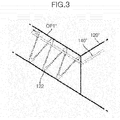
FIG. 3 is a diagram schematically showing a first cap and a bypass tube of a fuel cell humidifier according to a third embodiment of the present disclosure. -
FIG. 4 is a diagram schematically showing a bypass tube according to an embodiment of the present disclosure. - The terminology used herein is for the purpose of describing particular embodiments only and is not intended to be limiting of the disclosure. As used herein, the singular forms "a," "an" and "the" are intended to include the plural forms as well, unless the context clearly indicates otherwise. It will be further understood that the terms "comprises" and/or "comprising," when used in this specification, specify the presence of stated features, integers, steps, operations, elements, and/or components, but do not preclude the presence or addition of one or more other features, integers, steps, operations, elements, components, and/or groups thereof. As used herein, the term "and/or" includes any and all combinations of one or more of the associated listed items. Throughout the specification, unless explicitly described to the contrary, the word "comprise" and variations such as "comprises" or "comprising" will be understood to imply the inclusion of stated elements but not the exclusion of any other elements. In addition, the terms "unit", "-er", "-or", and "module" described in the specification mean units for processing at least one function and operation, and can be implemented by hardware components or software components and combinations thereof.
- Hereinafter, embodiments of the present disclosure will be described in detail with reference to the accompanying drawings.
-
FIG. 1 is a cross-sectional diagram of a fuel cell humidifier according to a first embodiment of the present disclosure. - A
fuel cell humidifier 100 of the present disclosure is a device for humidifying air supplied from an outside with moisture in off-gas discharged from a fuel cell stack (not shown), and supplying the humidified air to the fuel cell stack. - As shown in
FIG. 1 , thehumidifier 100 of the present disclosure includes ahumidification module 110 having first andsecond termination ends first cap 120 having an air discharge port (OP1) for supplying the humidified air to the fuel cell stack and coupled to thefirst termination end 110a, and asecond cap 130 having an air inlet port (IP1) for receiving the air supplied from the outside and coupled to thesecond termination end 110b. - The air discharge port (OP1) of the
first cap 120 and the air inlet port (IP1) of thesecond cap 130 are spaced apart from thehumidification module 110, respectively. - The
humidification module 110 includes ahousing 111 and a plurality ofhollow fiber membranes 112 disposed in thehousing 111. Thehousing 111 has an off-gas inlet port (IP2) for receiving off-gas from a fuel cell stack and an off-gas outlet port (OP2) for discharging the off-gas. - As shown in
FIG. 1 , thehousing 111 according to an embodiment of the present disclosure includes afirst housing 111a including thehollow fiber membranes 112 and asecond housing 111b surrounding thefirst housing 111a and having the off-gas inlet port (IP2) and the off-gas outlet port (OP2), and thefirst housing 111a has a first group of openings (H1) corresponding to the off-gas inlet port (IP2) and a second group of openings (H2) corresponding to the off-gas outlet port (OP2). - Both termination ends of the
hollow fiber membrane 112 are potted to first fixing layers 113 formed, respectively, in both termination ends of thefirst housing 111a, respectively, and both termination ends of thefirst housing 111a are fixed to both termination ends of thesecond housing 111b through second fixing layers 114, respectively. - Alternatively, the
housing 111 of the present disclosure may be a single housing including thehollow fiber membranes 112. In this case, both termination ends of thehollow fiber membrane 112 may be potted to the fixed layers formed, respectively, in both termination ends of the single housing, respectively. - According to another embodiment of the present disclosure, the
hollow fiber membranes 112 may include two or more hollow fiber membrane bundles, and thehousing 111 may include two or morefirst housings 111a including the two or more hollow fiber membrane bundles, respectively, and thesecond housing 111b surrounding thefirst housings 111a and having the off-gas inlet port (IP2) and the off-gas outlet port (OP2), and each of thefirst housings 111a may have the first group of openings (H1) corresponding to the off-gas inlet port (IP2) and the second group of openings (H2) corresponding to the off-gas outlet port (OP2). - According to the present disclosure, the interior space of the
first cap 120 and the interior space of thesecond cap 130 are in fluid communication with each other only through the lumens of thehollow fiber membranes 112. The interior space of thefirst cap 120 is defined by the inner surface of thefirst cap 120 and thefirst termination end 110a of thehumidification module 110, and the interior space of thesecond cap 130 is defined by the inner surface of thesecond cap 130 and thesecond termination end 110b of thehumidification module 110. - The off-gas flowing into the
housing 111 through the off-gas inlet port (IP2) contacts thehollow fiber membranes 112 while flowing in the interior space of thehousing 111 and then is discharged to the outside of thehousing 111 through the off-gas outlet port (OP2). - The air flowing into the interior space of the
second cap 130 from the outside through the air inlet port (IP1) flows into the interior space of thefirst cap 120 through the lumens of thehollow fiber membranes 112 and then is supplied to the fuel cell stack through the air discharge port (OP1). - When air flows along the lumen of the
hollow fiber membrane 112, the moisture contained in the off-gas flowing through the interior space of thehousing 111 passes through thehollow fiber membrane 112 to be transferred to the air, such that the air is humidified, and the humidified air flows into the interior space of thefirst cap 120 and then is supplied to the fuel cell stack through the air discharge port (OP1). - As described above, the condensate water generated by condensation of the humidified air in the lumen of the
hollow fiber membrane 112 or in the interior space of thefirst cap 120 should be prevented from flowing into the fuel cell stack. For this purpose, as shown inFIG. 1 , thefuel cell humidifier 100 of the present disclosure further includes abypass tube 140. - The
bypass tube 140 of the present disclosure may transfer the condensate water generated in the interior space of thefirst cap 120 or flowing into the interior space of thefirst cap 120 from thehollow fiber membranes 112 to the interior space of thehousing 111 through which the off-gas flows. - According to the present disclosure, a first end of the
bypass tube 140 is positioned in the air discharge port (OP1), and thebypass tube 140 is in fluid communication with the interior space of the housing 111 (i.e., the space through which the off-gas flows) through a second end of thebypass tube 140. For example, the second end of thebypass tube 140 may be positioned in the interior space of the housing 111 (i.e., the space through which the off-gas flows). The condensate water flowing into the air discharge port (OP1) may flow into the interior space of thehousing 111 along thebypass tube 140 by the air pressure difference, thereby preventing the condensate water from being transferred to the fuel cell stack. - In order to move the condensate water, which is generated in the interior space of the
first cap 120 or flows into the interior space of thefirst cap 120 from thehollow fiber membranes 112, to the fuel cell stack, it should necessarily pass through the air discharge port (OP1) of thefirst cap 120, such that the first end of thebypass tube 140 may be positioned in the air discharge port (OP1), thereby considerably preventing the condensate water generated by the condensation of the humidified air from flowing into the fuel cell stack. - Although the position of the
bypass tube 140 is not specially limited in the present disclosure, as shown inFIG. 1 , it may be disposed in the interior space of thefirst cap 120 and the interior space of thehousing 111 so that thebypass tube 140 is not exposed to the outside. When thebypass tube 140 is not exposed to the outside, the condensate water may be prevented from being frozen in thebypass tube 140 even in a cold environment. Accordingly, the condensate water may be prevented from flowing into the fuel cell stack without bypassing due to the freezing of the condensate water in thebypass tube 140. - As shown in
FIG. 1 , arib 121 may be provided in the air discharge port (OP1) in order to prevent the condensate water from being transferred to the fuel cell stack through the air discharge port (OP1). Therib 121 prevents the condensate water flowing into the air discharge port (OP1) from flowing further toward the fuel cell stack. The condensate water whose flow has been blocked by therib 121 is collected under therib 121. Accordingly, as shown inFIG. 1 , the first end of thebypass tube 140 may be positioned adjacent to therib 121. That is, the first end of thebypass tube 140 may be positioned between the main body of thefirst cap 120, the boundary of the air discharge port (OP1), and therib 121. - As described above, by switching from the low current mode to the high current mode, the condensate water that has been stagnant in the
hollow fiber membranes 112 is discharged from thehollow fiber membranes 112 together with the high pressure air when the external air is suddenly supplied at high pressure to flow into the air discharge port (OP1). However, since therib 121 does not block the entire passage of the air discharge port (OP1), it may not be said that there is no risk in which some of the condensate water discharged from thehollow fiber membranes 112 to flow into the air discharge port (OP1) may not be blocked by therib 121 and transferred to the fuel cell stack. - In order to minimize this risk, as shown in
FIG. 2 , an air discharge port (OP1') of a first cap 120' according to another embodiment of the present disclosure may have a longitudinal direction that is not parallel to the longitudinal direction of thehollow fiber membranes 112. For example, it is possible to form the air discharge port (OP1') so that the humidified air may flow upwards at a predetermined angle, thereby blocking most of the condensate water discharged in the longitudinal direction of thehollow fiber membrane 112 by a rib 121'. - However, in order to block the flow of the condensate water, not only the
ribs 121, 121' need to have a certain size or more, but also have a surface perpendicular to the flow of the humidified air, such that there is a risk of reducing the power generation efficiency of the fuel cell because excessive resistance is applied to the flow of the humidified air. - In order to counteract this risk, as shown in
FIG. 3 , afirst cap 120" according to still another embodiment of the present disclosure may include ascrew thread 122 formed on the inner surface of an air discharge port (OP1"). Thescrew thread 122 provides a spiral path to the condensate water flowing into the air discharge port (OP1"). - The
screw thread 122 may replace therib 121 ofFIG. 1 . That is, thescrew thread 122 of the present disclosure may also be formed on the inner surface of the air discharge port (OP1) extending in the direction parallel to the longitudinal direction of thehollow fiber membrane 112. However, as shown inFIG. 3 , when the air discharge port (OP1") is inclined so that the humidified air may flow upwards at a predetermined angle, there is further advantageous in that substantially all condensate water flowing into the air discharge port (OP1") may be guided by thescrew thread 122. - In order to transfer the condensate water that flows into the air discharge port (OP1") to reach the termination portion of the
screw thread 122 through the spiral path to the interior space of thehousing 111, a first end of abypass tube 140" may be positioned adjacent to the termination portion of thescrew thread 122. That is, the first end of thebypass tube 140" is disposed to receive all of the condensate water moved to the termination portion of thescrew thread 122 through the spiral path. - According to an embodiment of the present disclosure shown in
FIG. 3 , it is possible not only to prevent the power generation efficiency of the fuel cell from being reduced because excessive resistance is applied to the flow of the humidified air, but also to transfer all condensate water generated due to the condensation of the humidified air, that is, the condensate water generated in the interior space of thefirst cap 120" but also the condensate water generated in the lumen of thehollow fiber membranes 112 to flow into the interior space of thefirst cap 120" to the interior space of the housing 111 (i.e., the space through which the off-gas flows), thereby completely or substantially completely preventing the condensate water from flowing into the running fuel cell stack. - The
bypass tubes FIGS. 1 to 3 , respectively may be a single monolithic tube. - Alternatively, as shown in
FIG. 4 , thebypass tubes first tube 141 fixed to thefirst caps second tube 142 fixed to thehumidification module 110, and the first andsecond tubes first caps humidification module 110, thefirst tube 141 may also be coupled to thesecond tube 142, thereby enhancing convenience and productivity of the manufacturing process of thehumidifier 100.
Claims (13)
- A fuel cell humidifier, comprising:the fuel cell humidifier for humidifying air supplied from outside with moisture in an off-gas discharged from a fuel cell stack and supplying the humidified air to the fuel cell stack,a humidification module comprising a housing and a plurality of hollow fiber membranes arranged in the housing;a first cap having an air discharge port for supplying the humidified air to the fuel cell stack and coupled to a first termination end of the humidification module, the air discharge port being spaced apart from the humidification module; anda bypass tube for transferring the condensate water generated from the humidified air to an interior space of the housing through which the off-gas flows,wherein a first end of the bypass tube is positioned in the air discharge port, andwherein the bypass tube is in fluid communication with the interior space of the housing through a second end of the bypass tube.
- The fuel cell humidifier of claim 1, further comprising a second cap having an air inlet port for receiving the air supplied from the outside and coupled to a second termination end of the humidification module at an opposite side of the first termination end.
- The fuel cell humidifier of claim 2,
wherein an interior space of the first cap, which is defined by an inner surface of the first cap and the first termination end of the humidification module, and an interior space of the second cap, which is defined by an inner surface of the second cap and the second termination end of the humidification module, are in fluid communication with each other only through lumens of the hollow fiber membranes. - The fuel cell humidifier of claim 1,
wherein the housing has an off-gas inlet port for receiving the off-gas from the fuel cell stack and an off-gas outlet port for discharging the off-gas. - The fuel cell humidifier of claim 4, wherein the housing comprises:a first housing comprising the hollow fiber membranes; anda second housing surrounding the first housing and comprising the off-gas inlet port and the off-gas outlet port, andwherein the first housing has a first group of openings corresponding to the off-gas inlet port and a second group of openings corresponding to the off-gas outlet port.
- The fuel cell humidifier of claim 4,
wherein the hollow fiber membranes comprise two or more hollow fiber membrane bundles,
wherein the housing comprises:two or more first housings comprising the two or more hollow fiber membrane bundles, respectively; anda second housing surrounding the first housings and having the off-gas inlet port and the off-gas outlet port, andwherein each of the first housings has a first group of openings corresponding to the off-gas inlet port and a second group of openings corresponding to the off-gas outlet port. - The fuel cell humidifier of claim 1,
wherein the condensate water is generated in an interior space of the first cap or flows into the interior space of the first cap from the hollow fiber membranes and then is transferred to the interior space of the housing through the bypass tube. - The fuel cell humidifier of claim 1,
wherein a longitudinal direction of the air discharge port and a longitudinal direction of the hollow fiber membranes are not parallel to each other. - The fuel cell humidifier of claim 1,
wherein the first cap has a rib configured to prevent the condensate water from being transferred to the fuel cell stack through the air discharge port, the rib being disposed in the air discharge port, and
wherein the first end of the bypass tube is positioned adjacent to the rib. - The fuel cell humidifier of claim 1,
wherein a screw thread for providing a spiral path to the condensate water is formed on the inner surface of the air discharge port. - The fuel cell humidifier of claim 10,
wherein the first end of the bypass tube is positioned adjacent to the termination portion of the screw thread, in order to transfer the condensate water, which flows into the air discharge port to reach the termination portion of the screw thread through the spiral path, to the interior space of the housing. - The fuel cell humidifier of claim 1, wherein the bypass tube comprises:a first tube fixed to the first cap; anda second tube fixed to the humidification module, andwherein the first and second tubes are detachably coupled.
- The fuel cell humidifier of claim 1,
wherein the bypass tube is not exposed to the outside.
Applications Claiming Priority (2)
| Application Number | Priority Date | Filing Date | Title |
|---|---|---|---|
| KR1020170038205A KR102298888B1 (en) | 2017-03-27 | 2017-03-27 | Humidifier for Fuel Cell |
| PCT/KR2018/002258 WO2018182178A1 (en) | 2017-03-27 | 2018-02-23 | Humidifier for fuel cell |
Publications (2)
| Publication Number | Publication Date |
|---|---|
| EP3588647A1 true EP3588647A1 (en) | 2020-01-01 |
| EP3588647A4 EP3588647A4 (en) | 2021-01-27 |
Family
ID=63676539
Family Applications (1)
| Application Number | Title | Priority Date | Filing Date |
|---|---|---|---|
| EP18778184.4A Pending EP3588647A4 (en) | 2017-03-27 | 2018-02-23 | HUMIDIFIER FOR FUEL CELL |
Country Status (6)
| Country | Link |
|---|---|
| US (1) | US11611090B2 (en) |
| EP (1) | EP3588647A4 (en) |
| JP (1) | JP7016882B2 (en) |
| KR (1) | KR102298888B1 (en) |
| CN (1) | CN110462905B (en) |
| WO (1) | WO2018182178A1 (en) |
Cited By (1)
| Publication number | Priority date | Publication date | Assignee | Title |
|---|---|---|---|---|
| WO2026082471A1 (en) * | 2024-10-15 | 2026-04-23 | Mahle International Gmbh | Humidifier for fuel cells with heatable outlet for condensed water |
Families Citing this family (9)
| Publication number | Priority date | Publication date | Assignee | Title |
|---|---|---|---|---|
| KR102812076B1 (en) | 2019-02-28 | 2025-05-22 | 현대자동차주식회사 | Apparatus for discharging water of the fuel cell and system of the same |
| KR102805455B1 (en) * | 2019-08-14 | 2025-05-15 | 현대자동차주식회사 | Humidifier for fuel cell |
| KR102709665B1 (en) * | 2019-11-29 | 2024-09-24 | 코오롱인더스트리 주식회사 | Cartridge of Humidifier for Fuel Cell and Humidifier for Fuel Cell and |
| KR102546259B1 (en) * | 2020-05-22 | 2023-06-21 | 코오롱인더스트리 주식회사 | Gasket assembly and fuel cell humidifier comprising it |
| KR102671833B1 (en) * | 2021-01-28 | 2024-06-03 | 코오롱인더스트리 주식회사 | Automatic flow control cartridge and fuel cell humidifier comprising it |
| KR102809757B1 (en) | 2021-03-09 | 2025-05-20 | 코오롱인더스트리 주식회사 | Humidifier for fuel cell |
| JP2022148162A (en) * | 2021-03-24 | 2022-10-06 | 本田技研工業株式会社 | Fuel cell system and its control method |
| KR102617329B1 (en) * | 2021-10-15 | 2023-12-27 | 엔브이에이치코리아(주) | Hollow fiber membrane cartridge assembly |
| KR20230173472A (en) * | 2022-06-17 | 2023-12-27 | 코오롱인더스트리 주식회사 | Humidifier for Fuel Cell and Packing Device of Humidifier for Fuel Cell |
Family Cites Families (18)
| Publication number | Priority date | Publication date | Assignee | Title |
|---|---|---|---|---|
| JP2001201121A (en) * | 2000-01-19 | 2001-07-27 | Honda Motor Co Ltd | Humidifier |
| JP2003065566A (en) | 2001-08-24 | 2003-03-05 | Honda Motor Co Ltd | Gas humidifier and gas humidification system |
| JP2005158429A (en) * | 2003-11-25 | 2005-06-16 | Nissan Motor Co Ltd | Hollow fiber membrane humidifier |
| JP2005156001A (en) * | 2003-11-25 | 2005-06-16 | Nissan Motor Co Ltd | Hollow fiber membrane humidifier |
| JP4418299B2 (en) * | 2004-05-25 | 2010-02-17 | 本田技研工業株式会社 | Humidifier |
| JP4441387B2 (en) * | 2004-11-08 | 2010-03-31 | 本田技研工業株式会社 | Humidifier |
| JP4109667B2 (en) * | 2004-11-24 | 2008-07-02 | 本田技研工業株式会社 | Humidifier |
| JP2008226529A (en) * | 2007-03-09 | 2008-09-25 | Toyota Motor Corp | Fuel cell system and humidifier |
| EP2507860B1 (en) * | 2009-12-04 | 2017-10-18 | Kolon Industries, Inc. | Humidifier for fuel cell |
| KR101220368B1 (en) * | 2010-08-30 | 2013-01-09 | 기아자동차주식회사 | Fuel cell system and humidification device of the same |
| WO2012136307A1 (en) * | 2011-04-06 | 2012-10-11 | Haldor Topsøe A/S | Process for production of sulphuric acid |
| KR101592423B1 (en) * | 2014-08-01 | 2016-02-18 | 현대자동차주식회사 | Humidification device for fuel cell and fuel cell system comprising the same |
| CN104993161B (en) * | 2015-06-30 | 2017-03-08 | 同济大学 | An experimental device for an air supply system of a vehicle-used proton exchange membrane fuel cell |
| KR101724898B1 (en) | 2015-09-11 | 2017-04-07 | 현대자동차주식회사 | Humidification device for fuel cell |
| KR101755516B1 (en) * | 2016-07-11 | 2017-07-07 | 현대자동차 주식회사 | Humidification device for fuel cell |
| KR101896323B1 (en) * | 2016-08-31 | 2018-09-07 | 현대자동차 주식회사 | Humidification device for fuel cell |
| KR102529371B1 (en) | 2016-11-02 | 2023-05-04 | 현대자동차 주식회사 | Humidification device for fuel cell |
| KR102446774B1 (en) * | 2017-11-15 | 2022-09-22 | 코오롱인더스트리 주식회사 | fuel cell membrane humidifier |
-
2017
- 2017-03-27 KR KR1020170038205A patent/KR102298888B1/en active Active
-
2018
- 2018-02-23 CN CN201880022086.4A patent/CN110462905B/en active Active
- 2018-02-23 JP JP2019552590A patent/JP7016882B2/en active Active
- 2018-02-23 WO PCT/KR2018/002258 patent/WO2018182178A1/en not_active Ceased
- 2018-02-23 US US16/499,126 patent/US11611090B2/en active Active
- 2018-02-23 EP EP18778184.4A patent/EP3588647A4/en active Pending
Cited By (1)
| Publication number | Priority date | Publication date | Assignee | Title |
|---|---|---|---|---|
| WO2026082471A1 (en) * | 2024-10-15 | 2026-04-23 | Mahle International Gmbh | Humidifier for fuel cells with heatable outlet for condensed water |
Also Published As
| Publication number | Publication date |
|---|---|
| JP7016882B2 (en) | 2022-02-07 |
| US11611090B2 (en) | 2023-03-21 |
| CN110462905A (en) | 2019-11-15 |
| CN110462905B (en) | 2023-02-17 |
| KR20180109108A (en) | 2018-10-08 |
| WO2018182178A1 (en) | 2018-10-04 |
| JP2020512664A (en) | 2020-04-23 |
| US20210111420A1 (en) | 2021-04-15 |
| KR102298888B1 (en) | 2021-09-08 |
| EP3588647A4 (en) | 2021-01-27 |
Similar Documents
| Publication | Publication Date | Title |
|---|---|---|
| EP3588647A1 (en) | Humidifier for fuel cell | |
| JP2022091833A (en) | Fuel cell membrane humidifier | |
| US5366818A (en) | Solid polymer fuel cell systems incorporating water removal at the anode | |
| US11335925B2 (en) | Fuel cell system and humidifier therefor | |
| KR101535026B1 (en) | Humidifier for Fuel Cell System | |
| KR101461874B1 (en) | Full cell system and its humidifying and cooling method | |
| US20090130495A1 (en) | Humidifying System | |
| KR101724454B1 (en) | Fuel cell system and humidification device of the same | |
| US7163760B2 (en) | Fuel cell stack having a bypass flow passage | |
| US6964824B2 (en) | Fuel cell and method of operating the same | |
| JP7438692B2 (en) | Humidifier for fuel cells | |
| CN116670871A (en) | Cartridge for humidifier for fuel cell and humidifier for fuel cell | |
| KR102791248B1 (en) | Humidifier for fuel cell | |
| US7090941B2 (en) | Fuel cell stack and a method of supplying reactant gases to the fuel cell stack | |
| JP2008103115A (en) | Humidifier for fuel cell | |
| EP4273976A1 (en) | Fuel cell humidifier | |
| JP2008108473A (en) | Humidification system for fuel cell | |
| KR101188839B1 (en) | Humidifier apparatus for fuel cell | |
| KR101920786B1 (en) | Humidfication device for fuel cell stack and fuel cell system using the same | |
| US20250270710A1 (en) | Water electrolysis system | |
| KR20090037671A (en) | Fuel cell | |
| KR20220007433A (en) | Humidifier for fuel cell | |
| JP2005158517A (en) | Hollow fiber membrane humidifier |
Legal Events
| Date | Code | Title | Description |
|---|---|---|---|
| STAA | Information on the status of an ep patent application or granted ep patent |
Free format text: STATUS: THE INTERNATIONAL PUBLICATION HAS BEEN MADE |
|
| PUAI | Public reference made under article 153(3) epc to a published international application that has entered the european phase |
Free format text: ORIGINAL CODE: 0009012 |
|
| STAA | Information on the status of an ep patent application or granted ep patent |
Free format text: STATUS: REQUEST FOR EXAMINATION WAS MADE |
|
| 17P | Request for examination filed |
Effective date: 20190927 |
|
| AK | Designated contracting states |
Kind code of ref document: A1 Designated state(s): AL AT BE BG CH CY CZ DE DK EE ES FI FR GB GR HR HU IE IS IT LI LT LU LV MC MK MT NL NO PL PT RO RS SE SI SK SM TR |
|
| AX | Request for extension of the european patent |
Extension state: BA ME |
|
| DAV | Request for validation of the european patent (deleted) | ||
| DAX | Request for extension of the european patent (deleted) | ||
| A4 | Supplementary search report drawn up and despatched |
Effective date: 20210112 |
|
| RIC1 | Information provided on ipc code assigned before grant |
Ipc: H01M 8/04119 20160101AFI20201221BHEP Ipc: B01D 63/02 20060101ALI20201221BHEP |
|
| RAP3 | Party data changed (applicant data changed or rights of an application transferred) |
Owner name: KOLON INDUSTRIES, INC. Owner name: HYUNDAI MOTOR COMPANY Owner name: KIA CORPORATION |
|
| STAA | Information on the status of an ep patent application or granted ep patent |
Free format text: STATUS: EXAMINATION IS IN PROGRESS |
|
| 17Q | First examination report despatched |
Effective date: 20230405 |
|
| P01 | Opt-out of the competence of the unified patent court (upc) registered |
Effective date: 20230512 |