EP3588428A1 - Pci correction - Google Patents
Pci correction Download PDFInfo
- Publication number
- EP3588428A1 EP3588428A1 EP18180185.3A EP18180185A EP3588428A1 EP 3588428 A1 EP3588428 A1 EP 3588428A1 EP 18180185 A EP18180185 A EP 18180185A EP 3588428 A1 EP3588428 A1 EP 3588428A1
- Authority
- EP
- European Patent Office
- Prior art keywords
- pci
- image
- images
- detector
- ray
- Prior art date
- Legal status (The legal status is an assumption and is not a legal conclusion. Google has not performed a legal analysis and makes no representation as to the accuracy of the status listed.)
- Granted
Links
Images



Classifications
-
- G—PHYSICS
- G06—COMPUTING OR CALCULATING; COUNTING
- G06T—IMAGE DATA PROCESSING OR GENERATION, IN GENERAL
- G06T5/00—Image enhancement or restoration
- G06T5/50—Image enhancement or restoration using two or more images, e.g. averaging or subtraction
-
- A—HUMAN NECESSITIES
- A61—MEDICAL OR VETERINARY SCIENCE; HYGIENE
- A61B—DIAGNOSIS; SURGERY; IDENTIFICATION
- A61B6/00—Apparatus or devices for radiation diagnosis; Apparatus or devices for radiation diagnosis combined with radiation therapy equipment
- A61B6/48—Diagnostic techniques
- A61B6/484—Diagnostic techniques involving phase contrast X-ray imaging
-
- A—HUMAN NECESSITIES
- A61—MEDICAL OR VETERINARY SCIENCE; HYGIENE
- A61B—DIAGNOSIS; SURGERY; IDENTIFICATION
- A61B6/00—Apparatus or devices for radiation diagnosis; Apparatus or devices for radiation diagnosis combined with radiation therapy equipment
- A61B6/52—Devices using data or image processing specially adapted for radiation diagnosis
- A61B6/5205—Devices using data or image processing specially adapted for radiation diagnosis involving processing of raw data to produce diagnostic data
-
- A—HUMAN NECESSITIES
- A61—MEDICAL OR VETERINARY SCIENCE; HYGIENE
- A61B—DIAGNOSIS; SURGERY; IDENTIFICATION
- A61B6/00—Apparatus or devices for radiation diagnosis; Apparatus or devices for radiation diagnosis combined with radiation therapy equipment
- A61B6/52—Devices using data or image processing specially adapted for radiation diagnosis
- A61B6/5258—Devices using data or image processing specially adapted for radiation diagnosis involving detection or reduction of artifacts or noise
- A61B6/5282—Devices using data or image processing specially adapted for radiation diagnosis involving detection or reduction of artifacts or noise due to scatter
-
- G—PHYSICS
- G06—COMPUTING OR CALCULATING; COUNTING
- G06T—IMAGE DATA PROCESSING OR GENERATION, IN GENERAL
- G06T5/00—Image enhancement or restoration
- G06T5/73—Deblurring; Sharpening
-
- G—PHYSICS
- G06—COMPUTING OR CALCULATING; COUNTING
- G06T—IMAGE DATA PROCESSING OR GENERATION, IN GENERAL
- G06T2207/00—Indexing scheme for image analysis or image enhancement
- G06T2207/10—Image acquisition modality
- G06T2207/10016—Video; Image sequence
-
- G—PHYSICS
- G06—COMPUTING OR CALCULATING; COUNTING
- G06T—IMAGE DATA PROCESSING OR GENERATION, IN GENERAL
- G06T2207/00—Indexing scheme for image analysis or image enhancement
- G06T2207/20—Special algorithmic details
- G06T2207/20212—Image combination
- G06T2207/20221—Image fusion; Image merging
Definitions
- Phase-contrast X-ray imaging is a general term for different technical methods that use information concerning changes in the phase of an X-ray beam that passes through an object in order to create its images.
- Standard X-ray imaging techniques like radiography or computed tomography (CT) rely on a decrease of the X-ray beam's intensity (attenuation) when traversing the sample, which can be measured directly with the assistance of an X-ray detector.
- CT computed tomography
- the beam's phase shift and scattering caused by the sample is not measured directly, but is transformed into variations in intensity, which then can be recorded by the detector.
- a further advantage of PCI in medical diagnosis is that, because the phase contrast image formation is not intrinsically linked to the absorption of X-rays in the sample, the absorbed dose can potentially be reduced by using higher X-ray energies potentially saving the patient from substantial dose depositions during X-ray image acquisition.
- Phase differences in X-ray beams cannot be directly measured by an X-ray detector, but require special interferometry techniques using diffraction gratings or an in-coherent setup with a plurality of apertures to produce the measurable effects at the X-ray detector.
- These measurable effects are small variations in the direction and width of X-ray beamlets obtained e.g. by means of a grating in between an X-ray source and a subject under examination, said variations being detected by means of an assembly of a detector mask placed before an X-ray detector.
- X-rays emitted from an X-ray source are shaped into individual beamlets by means of selective absorption by a so-called “pre-sample mask” or “coded aperture” (which is an absorbing grating).
- the pre-sample mask allows only narrow portions of the X-ray beam to pass through so-called apertures of identical width.
- This pre-sample mask traditionally has a fixed geometry that is adapted to an analyser grating that in its turn is fitted to the geometry of the used X-ray detector pixel grid dimensions while taking into account the distances between the X-ray source, pre-sample mask and X-ray detector.
- the analyser grating also called “detector grating" blocks a part of the beamlets dependent on the relative position of the beamlet and the analyzer grating.
- the pitch of the beamlet structure (determining the X-ray intensity profile) and the analyzer grating are adapted to the pitch of the detector.
- These narrow beamlets pass through a sample or object and arrive at individual pixels of the X-ray detector through said analyser grating.
- the individual X-ray beamlets are arranged to hit the pixel edge of individual rows of pixels or individual columns of pixels or individual pixels. Small deviations in the individual beamlets cause a significant increase or decrease in the signal hitting the exposed area of the pixel resulting in a significant phase contrast or dark field signal.
- the physical analyser grating blocks by definition a considerable portion of the radiation passing the imaged object or patient, and that does not contribute to the image acquisition.
- the physical analyser grating intrinsically reduces the yield of the applied radiation dose.
- the first effect is the pure deflection of the X-ray beamlets influenced by the shape of the object or large structures inside the object (large in this context means some 100 ⁇ m in diameter) and giving rise to the "phase image”.
- the re-calculation of the phase image is based on the difference of two images recorded at different positions of the analyser grating (or different sets of pixels for the approach of virtual analyser grating).
- the classical absorption x-ray image is denoted as t ;
- ⁇ x R is the phase image and
- ⁇ M 2 the dark field image.
- Visualization of the effects of beam deflections on the recalculating of the phase images and the scatter images are depicted in Fig.1 and Fig. 2 respectively.
- Fig. 3 the original situation is depicted on the left side wherein the doses recorded in 2 neighbouring pixels (10) and (11) are equal in the case of an undisturbed X-ray beam (i.e. the X-ray beamlet is not influenced by any deflection by the imaged object or patient).
- the situation on the right side of Fig. 3 represents the case where there is beam deflection resulting in a shift to the right of the centre of the beamlet.
- pixel (11) will record an increased dose at the expense of a decreased dose recorded in pixel (10).
- the difference between pixel (10) and (11) can be understood as a measure for the phase change.
- Fig. 4 shows the effect of beam broadening by scatter.
- the beam gets broader and lower (scatter leaves the area under the curve unchanged - no absorption). Due to beam broadening a part of the intensity is deflected to the neighbouring pixels.
- the dose captured in both pixels (10) and (11) goes down by the same amount.
- phase image the profile shifts off-centre.
- the phase effect therefore is overestimated (and therefore wrong).
- the scatter image the profile becomes steeper, i.e. the scatter effect is underestimated.
- a high-resolution PCI image is either a phase image or a dark field image that has been acquired at a high spatial resolution, for instance at the native resolution of conventional X-ray detector, wherein each detector pixel corresponds to an image pixel in the resulting PCI image.
- the method described here is based on the principle that while the reconstruction of a single pixel of a PCI image requires a profile measurement of a set of ( n ) neighbouring pixels (and thus intrinsically decreases the spatial resolution of the resulting PCI image by a factor n ), this loss in spatial resolution can be compensated by acquiring additional acquisitions of n x-ray absorption images.
- the pre-sample mask in a specific embodiment is shifted in a direction parallel to the plane of the detector and so that pixels of the pixel matrix which were not irradiated are now available and can be used to calculate a second, third etc. set of absorption, phase images and dark field images by applying the method described higher.
- This shifting of the pre-sample mask is done at most n-1 times in order to obtain n x-ray absorption images in total to leverage the full spatial resolution of the digital image detector.
- the PCI system to which the method may be applied comprises an X-ray source, a pre-sample mask (or beam splitter) and a digital imaging detector.
- the PCI system of this invention does not have a physical analyser grating or detector mask, which - although being an essential component of a coded aperture PCI system- is replaced by a so-called virtual analyser grating or virtual grating, as disclosed in patent application ( EP17181154.0 ).
- This virtual grating replaces the presence and function of a physical analyser grating by selectively reading out predetermined sequences of detector pixel groups of the same image, rather than physically blocking incident radiation by grating bars.
- absorption gradient artefacts are image artefacts in the phase image or the dark field image which are caused by the presence in the imaged object of a steep gradient in electron density in the imaged object. These steep gradients typically occur at transitions between tissues of different densities (e.g. between tissue and air). The consequence is that in the phase image, the phase effect is overestimated (the profile shifts off-centre), and the dark field image the scatter effect is underestimated (as the profile becomes more steep).
- An absorption image is a conventional X-ray absorption image.
- normalization of a measured profile means that the maximum value of the profile (that is to be normalized) is mathematically compared with the maxima of at least two neighbouring measured profiles, and then adjusted to the mean of the calculated maxima.
- the neighbouring profiles are defined as the profiles of which the centres coincide with the neighbouring pixels of the centre of the profile to be normalized.
- ⁇ 0 ; I 2
- ⁇ 0 ⁇ c I 1
- ⁇ ⁇ ⁇ ⁇ ; I 2
- ⁇ ⁇ ⁇ ⁇ ; I 1
- ⁇ + ⁇ ⁇ ; I 2
- ⁇ 0 ; I 2
- ⁇ 0 / c I 1
- ⁇ ⁇ ⁇ ⁇ ; I 2
- ⁇ ⁇ ⁇ ⁇ ; I 1
- ⁇ + ⁇ ⁇ ; I 2
- ⁇ + ⁇ ⁇ ⁇ ⁇
- Normalization in general means to divide a set of values by a number to either make the maximum equal to one or the integral of the data set equal to one.
- the intensity follows an exponential decay: I ⁇ e - ⁇ ( x ) ⁇ z with ⁇ (x) being the local mean absorption coefficient along the path z through the object.
- the normalization procedure depends on whether the intensity impinging on the detector pixel or the logarithm of this value is used to calculate the correction term.
- the present invention can be implemented as a computer program product adapted to carry out the steps as set out in the description.
- the computer executable program code adapted to carry out the steps set out in the description can be stored on a computer readable medium.
- the present invention is an improvement to the technique referenced above in EP17181154.0 and reduces a number of very specific image artefacts which may occur due to the presence of steep X-ray absorption gradients in the imaged objects.
- the invention is advantageous in that the method allows for reducing artefacts in the PCI image which are caused by steep absorption gradients in the imaged object without the need to acquire additional images for this purpose.
- Fig. 3 illustrates the effect of beam deflection on a beamlet caused by phase effects on an X-ray beam when passing through material.
- the left graph shows the situation of an undisturbed beamlet that is centred in the middle between two neighbouring detector pixels; the radiation detected by the two pixels is equally distributed.
- the graph on the right shows the situation where beam deflection occurred.
- the x-ray power incident on the left pixel (10) is reduced while the x-ray power incident on the right pixel (11) is increased.
- the difference between the left (10) and right pixel (11) can be understood as a measure for the phase change.
- Fig. 4 illustrates the effect of beam broadening caused by scatter. Compared to the undisturbed beamlet (in the left graph), the beamlet gets broader and lower when subjected to (scatter leaves the area under the curve unchanged - as there is no absorption). Due to beam broadening a part of the intensity is deflected to the neighbouring pixels. The pixel value of the left (10) and right pixel (11) goes down by the same amount, as can be seen in the graph on the right.
- Fig. 5 illustrates the effect of the presence of a linear absorption gradient on a beamlet; for the phase image the net effect is that the centre of the measurement profile (12) is shifted (14) to the right (13) in this case (see left graph), which mimics the same effect as if there would have been a beam deflection. Consequently, the profile shifts off-centre to the right and the phase effect is overestimated in the phase image.
- Fig. 9 represents a FFT (Fast Fourier Transformation) of a PCI acquisition (using a pre-sample mask) of a real object and shows the effect on the FFT magnitude.
- the changes in the 0th order are caused by absorption.
- the 0th order peak is visible (40).
- the changes in the 1 st order magnitude are caused by beam broadening and the changes of the 1 st order phase represent the phase image.
- the 1 st order peak is visible as (41), (42) is the -1 st order peak.
- the regions (50) and (51) in the transformed image represent respectively the 0 th and 1 st order Fourier Transformed portion of the image data that may be separated from the rest of the image and transformed back to obtain respectively the absorption image and the refracted image.
- This method to reduce the artefacts is based on a clever re-use of suitable acquired profile data that already was part of the acquisition data set made for the purpose of achieving full-resolution PCI images.
- the raw acquired absorption measurement data in combination with the application of a so-called virtual grating unexpectedly allows to extract the necessary information to correct the phase and dark field image data.
- the aperture size a should be smaller than or equal to half the pitch of the pre-sampling mask in order to produce the desired profile shape to perform the desired profile measurements: a ⁇ p pm 2
- the number of pixels n should only cover the amount needed to record a meaningful intensity profile for a single beamlet.
- the number of detector pixels n thus determines the width of the measured profile, but will then also require that the dimensions of the pre-sample mask and the magnification M are adapted to this choice (as explained above).
- a higher value of n allows a smoother profile measurement for one PCI image pixel, but at the same time reduces the spatial resolution of the image, which can however be compensated by acquiring n acquisitions (the higher the value of n, the more acquisitions are required to achieve the same spatial resolution).
- the number n equals 4, which can be considered to be the absolute minimum.
- n is chosen to equal 4.
- this is not a limitation for the applicability of this invention.
- n acquired x-ray absorption images are represented in Fig. 6 as images I, II, III and IV.
- pre-sample mask grating bars (32) are shifted as indicated by the arrows for each of the acquisitions I to IV. Consequently, the radiation profiles also shift to expose a different set of detector pixels (30).
- Each set of said detector pixels (30) will allow to reconstruct one pixel in the phase and dark field image.
- phase image In conventional PCI imaging, a portion of the pixels of the digital image detector would have to be blocked (by the grating bars of the analyser grating) in order to obtain the necessary image data to reconstruct the phase and dark filed images.
- the re-calculation of the phase image is based on the difference of two images recorded at different positions of the analyser grating.
- the scatter image typically uses the sum of two normalized images. This means that multiple images need to be acquired for the same pre-sample mask position in order to be able to reconstruct a single phase or dark field image.
- Fig. 6 illustrates the pixel modulation that is applied by the virtual grating on each sequence of 4 detector pixels (30).
- the different pixel modulations (A, B, C and D) are shown for each of the n acquired x-ray absorption images (I, II, III and IV) in the respective columns.
- the active/inactive pixels are shown with a different shading color.
- One of the 4 modulations is not used for image reconstruction, as this sequence does not capture any of the pixel values in the center of the radiation profile (this corresponds to a grating bar blocking the central part of the profile). These unused modulations are crossed-out in Fig. 6 .
- a periodic image such as an intensity modulated image by a grating
- a Fourier transform with a 0-order (that is related to the constant part of the image), a 1st order related to the main frequency of the modulation (i.e. the frequency of the pre-sample mask) and higher orders (harmonics) which are related to multiples of the frequency of the 1st order.
- Refraction and scatter influence the periodic part of the intensity profile and thus cause changes in the 1st order peak of the Fourier transformation.
- the complex 2D Fourier transform thus has a characteristic look as shown in Fig. 9 on which identifiable peaks are visible.
- the 2D Fourier transformed image shows 3 identifiable regions (or sub-arrays) centered on 3 clearly identifiable peaks.
- a first region (50) is centered on the 0th order peak (40) and the region height is defined by the distance (55) (expressed in number of pixels) between the 0th and 1st order peak.
- the width of this region is defined by the width of the raw image as we use a 1D grating.
- a second region is centered at the 1st order peak (51) and again the region height is defined by the distance (55) between the 0th and 1st order peak.
- the obtained images would be uncorrected for gradient artefacts.
- the conventional approach using a physical analyser grating
- the normalization would be done in the case of our preferred embodiment of 4 pixel-sized sets with the at least 2 neighbouring (left and right) profiles.
- Fig. 7 illustrates for our example which profile data should be taken into consideration for the normalisation step of certain a exposure (I, II, III or IV).
- the profile spanning the full 4 pixels of the pixel set can be used to normalize the profile data used to reconstruct the PCI images.
- the normalization of a certain measured profile is performed by comparing the maximum of this considered measurement profile with the maxima of the profiles centred on its closest neighbouring pixels. A deviation between the considered maximum and the respective neighbouring maxima vouches for the presence of an absorption gradient. The maximum of the measured profile in question can then be adjusted to better align to the values of its neighbours. This alignment is achieved through normalisation, or through any other means of adjustment.
- phase ph typically consists of two terms: an uncorrected phase ph nc and a correction term c .
- the terms are functions of the pixel values I 1 & I 2 , representing the 2 most central pixels of the set of 4 pixels (refer to Fig. 7 ).
- ph ph nc I 1
- ⁇ 0 ;
- ⁇ 0 ⁇ c I 1
- ⁇ ⁇ ⁇ ⁇ ;
- ⁇ ⁇ ⁇ ⁇ ; I 1
- ⁇ + ⁇ ⁇ ; I 2
- ⁇ + ⁇ ⁇ ⁇
- the correction factor c depends on the exact geometry of the setup and to some extend also on the absorption and transmission of the pre-sample mask
- the method described above can also be applied to correct scatter image re-calculation.
- the approach is similar.
- the main difference is the calculation of the correction factor c.
- the absorption gradient correction can be used to correct phase images and to correct scatter images in an almost similar way as the effect on the shape of the intensity profile of a beamlet is similar in both cases. I.e. an absorption gradient shifts and narrows the profile of a beamlet - for phase correction the shift has to be calculated for scatter correction the narrowing has to be calculated.
Landscapes
- Engineering & Computer Science (AREA)
- Life Sciences & Earth Sciences (AREA)
- Health & Medical Sciences (AREA)
- Medical Informatics (AREA)
- Physics & Mathematics (AREA)
- Radiology & Medical Imaging (AREA)
- Heart & Thoracic Surgery (AREA)
- High Energy & Nuclear Physics (AREA)
- Veterinary Medicine (AREA)
- Nuclear Medicine, Radiotherapy & Molecular Imaging (AREA)
- Optics & Photonics (AREA)
- Pathology (AREA)
- Public Health (AREA)
- Biomedical Technology (AREA)
- Biophysics (AREA)
- Molecular Biology (AREA)
- Surgery (AREA)
- Animal Behavior & Ethology (AREA)
- General Health & Medical Sciences (AREA)
- General Physics & Mathematics (AREA)
- Theoretical Computer Science (AREA)
- Computer Vision & Pattern Recognition (AREA)
- Image Processing (AREA)
- Analysing Materials By The Use Of Radiation (AREA)
Abstract
Description
- This invention is related to phase contrast imaging, more specifically to a method to reduce specific artefacts that may occur during acquisition and processing. Reference is made in the embodiments to particular examples in medical imaging.
- Phase-contrast X-ray imaging (PCI) is a general term for different technical methods that use information concerning changes in the phase of an X-ray beam that passes through an object in order to create its images. Standard X-ray imaging techniques like radiography or computed tomography (CT) rely on a decrease of the X-ray beam's intensity (attenuation) when traversing the sample, which can be measured directly with the assistance of an X-ray detector. In PCI however, the beam's phase shift and scattering caused by the sample is not measured directly, but is transformed into variations in intensity, which then can be recorded by the detector.
- When applied to samples that consist of atoms with low atomic number Z, PCI is more sensitive to density variations in the sample than conventional transmission-based X-ray imaging. This leads to images with improved soft tissue contrast, hence the particular interest for this technique in medical imaging. Tissue containing a lot of density transitions, such as lung tissue, generates a lot of scatter which makes it highly visible in the scatter image of a phase contrast image.
- Conventional X-ray imaging uses the drop in intensity through attenuation caused by an object in the X-ray beam and the radiation is treated as rays like in geometrical optics. But when X-rays pass through an object, not only their amplitude but their phase and propagation direction is altered as well. When applying the values of typical human tissue, the phase-shift of an X-ray beam propagating through tissue is up to three orders of magnitude larger than the loss in intensity caused by the absorption by the same tissue, thus making PCI more sensitive to density variations in soft tissue than absorption imaging.
- A further advantage of PCI in medical diagnosis is that, because the phase contrast image formation is not intrinsically linked to the absorption of X-rays in the sample, the absorbed dose can potentially be reduced by using higher X-ray energies potentially saving the patient from substantial dose depositions during X-ray image acquisition.
- Phase differences in X-ray beams cannot be directly measured by an X-ray detector, but require special interferometry techniques using diffraction gratings or an in-coherent setup with a plurality of apertures to produce the measurable effects at the X-ray detector. These measurable effects are small variations in the direction and width of X-ray beamlets obtained e.g. by means of a grating in between an X-ray source and a subject under examination, said variations being detected by means of an assembly of a detector mask placed before an X-ray detector.
- Basically two approaches exist to produce said measurable effects:
- 1. An interferometric approach which uses a partially coherent source of radiation referred to as Talbot-Lau interferometry.
- 2. A completely in-coherent approach with repeated edge illumination referred to as Coded Aperture Phase Contrast Imaging.
- The present invention is applicable to the second approach and will be described further on with reference to the Coded Aperture Phase Contrast Imaging technique. The present invention is not limited to this embodiment. The principle of coded aperture phase contrast imaging (PCI) has been described in US 7, 869, 567.
- For Coded Aperture Phase Contrast Imaging to work, X-rays emitted from an X-ray source are shaped into individual beamlets by means of selective absorption by a so-called "pre-sample mask" or "coded aperture" (which is an absorbing grating). The pre-sample mask allows only narrow portions of the X-ray beam to pass through so-called apertures of identical width. This pre-sample mask traditionally has a fixed geometry that is adapted to an analyser grating that in its turn is fitted to the geometry of the used X-ray detector pixel grid dimensions while taking into account the distances between the X-ray source, pre-sample mask and X-ray detector. The analyser grating, also called "detector grating", blocks a part of the beamlets dependent on the relative position of the beamlet and the analyzer grating. The pitch of the beamlet structure (determining the X-ray intensity profile) and the analyzer grating are adapted to the pitch of the detector.
- These narrow beamlets pass through a sample or object and arrive at individual pixels of the X-ray detector through said analyser grating. The individual X-ray beamlets are arranged to hit the pixel edge of individual rows of pixels or individual columns of pixels or individual pixels. Small deviations in the individual beamlets cause a significant increase or decrease in the signal hitting the exposed area of the pixel resulting in a significant phase contrast or dark field signal.
- At the same time, the physical analyser grating blocks by definition a considerable portion of the radiation passing the imaged object or patient, and that does not contribute to the image acquisition. The physical analyser grating intrinsically reduces the yield of the applied radiation dose.
- In an earlier filed patent application (
EP17181154.0 - As suggested above, there exist two types of measurable effects caused by said aforementioned incidence of X-ray beamlets on an object and causing said small deviations.
- The first effect is the pure deflection of the X-ray beamlets influenced by the shape of the object or large structures inside the object (large in this context means some 100 µm in diameter) and giving rise to the "phase image".
- Secondly, scattering of the X-ray beamlets passing through an object and influenced by the path-length of the beam through the object -and thus by the size and internal small structures (small in this context means below 100 µm in diameter) of the object- giving rise to the "scatter image" or "dark field image".
- Typically, the re-calculation of the phase image is based on the difference of two images recorded at different positions of the analyser grating (or different sets of pixels for the approach of virtual analyser grating). The scatter image typically uses the sum of two normalized images, as determined by the following equation system:

- In the above equation, the classical absorption x-ray image is denoted as t; ΔxR is the phase image and

Fig.1 andFig. 2 respectively. - In
Fig. 3 the original situation is depicted on the left side wherein the doses recorded in 2 neighbouring pixels (10) and (11) are equal in the case of an undisturbed X-ray beam (i.e. the X-ray beamlet is not influenced by any deflection by the imaged object or patient). The situation on the right side ofFig. 3 represents the case where there is beam deflection resulting in a shift to the right of the centre of the beamlet. In this case, pixel (11) will record an increased dose at the expense of a decreased dose recorded in pixel (10). The difference between pixel (10) and (11) can be understood as a measure for the phase change. -
Fig. 4 shows the effect of beam broadening by scatter. The beam gets broader and lower (scatter leaves the area under the curve unchanged - no absorption). Due to beam broadening a part of the intensity is deflected to the neighbouring pixels. The dose captured in both pixels (10) and (11) goes down by the same amount. - Now the problem to be solved becomes obvious: if the imaged object is absorbing part of the incident radiation, this effect will also lead to a decrease of the doses recorded by both pixels (10) and (11). To discriminate between a dose reduction due to absorption or to scatter effects, it is necessary to normalize the pixel values in some way. In the situations known in the state of the art, this is typically achieved by recording a third image with the pixels centred to the intensity profile. This approach however implies that an additional acquisition has to be made (with an effect of increased dose for the patient).
- Moreover, even when an additional exposure is made to allow the normalisation, this approach will not work under certain circumstances. In the case that a strong absorption gradient is present in the imaged object, this causes a difference between the readings of the first (10) and second pixel (11) even without a phase gradient and thus mimics a beam deflection.
- The impact of an absorption gradient can be illustrated by means of a simple graphical simulation (refer to the left graph in
Fig. 5 ). A Gaussian profile (12) was multiplied with a linear function which represents the absorption gradient. The result of such a superposition (13) is that the centre of the profile shifts with increasing gradient to the right (14). Using standard re-calculation would lead to a wrong phase image. Moreover the absorption gradient slightly decreases the width of the profile. With standard re-calculation this would be interpreted as negative scattering coefficient which is physically impossible. - The effects of a steep absorption gradient have an impact in both the phase image and the scatter image. In phase image, the profile shifts off-centre. The phase effect therefore is overestimated (and therefore wrong). In the scatter image, the profile becomes steeper, i.e. the scatter effect is underestimated.
- To solve this problem, typically additional images acquired with different positions of the pre-sampling mask and the analyser grating are recorded. To calculate the uncorrected phase image at least two images at different positions of the analyser grating are needed. To correct for absorption gradients 4 additional images are recorded at 2 different positions of the pre-sampling mask and for each position of the pre-sampling mask 2 images with different positions of the analyser grating.
- These 4 additional images are only used to calculate the absorption gradient. This increases recording time and dose. Moreover 2 motorized stages are needed: one to move the pre-sampling mask the other to move the analyser grating.
- In summary, the state of the art approach to compensate for the effects of a steep absorption gradient leads to three disadvantages: longer recording time, high dose (to patient) and a higher complexity of the system.
- For the sake of completeness it has to be mentioned that there are phase contrast imaging system designs which produce only very small artefacts in the presence of an absorption gradient. These designs however require mini-focal-spot x-ray tubes (spot size <100 µm) and very fine grating structures (pitch < 100 µm). Such systems only have very little chances to fulfil the requirements for clinical applications. Their X-ray flux is much too low to make an X-ray image with acceptable quantum noise in an acceptable time. Their grids are very hard to produce and will be much too costly for a medical X-ray system with an acceptable price. An X-ray sensor is needed with pixels that are smaller than the pixels of current medical flat-panel detectors.
- The present invention provides a method for generating a high-resolution PCI image corrected for absorption gradient artefacts on a PCI system, comprising the steps of acquiring a series of n ≥4 x-ray absorption images on an x-ray detector, acquiring said x-ray absorption images at n different positions ξ 1→n of a pre-sample mask in said PCI system, wherein

Claim 1. - In the context of this invention, a high-resolution PCI image is either a phase image or a dark field image that has been acquired at a high spatial resolution, for instance at the native resolution of conventional X-ray detector, wherein each detector pixel corresponds to an image pixel in the resulting PCI image. The method described here is based on the principle that while the reconstruction of a single pixel of a PCI image requires a profile measurement of a set of (n) neighbouring pixels (and thus intrinsically decreases the spatial resolution of the resulting PCI image by a factor n), this loss in spatial resolution can be compensated by acquiring additional acquisitions of n x-ray absorption images.
- When a pre-sample mask or beam splitter is used in the radiation path from X-ray source to detector some detector pixels of the detector are not irradiated. Hence the total pixel resolution of the detector is not used. In order to increase the resolution again, the pre-sample mask in a specific embodiment is shifted in a direction parallel to the plane of the detector and so that pixels of the pixel matrix which were not irradiated are now available and can be used to calculate a second, third etc. set of absorption, phase images and dark field images by applying the method described higher. This shifting of the pre-sample mask is done at most n-1 times in order to obtain n x-ray absorption images in total to leverage the full spatial resolution of the digital image detector. These additional acquisitions need to fulfil certain criteria matching the geometry of the PCI system.
- In the context of this invention, the PCI system to which the method may be applied comprises an X-ray source, a pre-sample mask (or beam splitter) and a digital imaging detector. The PCI system of this invention does not have a physical analyser grating or detector mask, which - although being an essential component of a coded aperture PCI system- is replaced by a so-called virtual analyser grating or virtual grating, as disclosed in patent application (
EP17181154.0 - The virtual grating is implemented as a virtual mask laid over the pixel matrix of the recorded pixel values and thereby "blocking" or "ignoring" some pixels so that their values are not used in the computation of the absorption, phase or dark field image while others remain available for use in the computation. By shifting the virtual mask so that pixels that were used in the computation of one of the above-mentioned images become blocked while other sets of (neighbouring) pixels become available for computation of one of these images. The virtual grid thus attains the same result as obtained by the moving analyser grating or detector mask in the state of the art.
- In the context of this invention, absorption gradient artefacts are image artefacts in the phase image or the dark field image which are caused by the presence in the imaged object of a steep gradient in electron density in the imaged object. These steep gradients typically occur at transitions between tissues of different densities (e.g. between tissue and air). The consequence is that in the phase image, the phase effect is overestimated (the profile shifts off-centre), and the dark field image the scatter effect is underestimated (as the profile becomes more steep).
- An absorption image is a conventional X-ray absorption image.
- In the context of the invention, an uncorrected image relates to whether or not a PCI image has been corrected for the absorption gradient artefacts.
- In the context of this invention, normalization of a measured profile means that the maximum value of the profile (that is to be normalized) is mathematically compared with the maxima of at least two neighbouring measured profiles, and then adjusted to the mean of the calculated maxima. The neighbouring profiles are defined as the profiles of which the centres coincide with the neighbouring pixels of the centre of the profile to be normalized. These neighbouring profiles are thus acquired by physically offsetting the pre-sample mask to directly neighbouring pre-sample mask positions, with a distance so that the projection at the level of the detector corresponds to the width of a detector pixel.
- Normalization may also be achieved by of subtracting the pixel values;


- Normalization in general means to divide a set of values by a number to either make the maximum equal to one or the integral of the data set equal to one. In case of X-ray absorption the intensity follows an exponential decay: I∼e-µ(x)·z with µ(x) being the local mean absorption coefficient along the path z through the object. Dependent on the type of normalization (normalizing by the local intensity variation or the local absorption coefficient variation) the normalization is a division or subtraction as µ∼ln(I) and

- Specific examples and preferred embodiments are set out in the dependent claims.
- The present invention can be implemented as a computer program product adapted to carry out the steps as set out in the description. The computer executable program code adapted to carry out the steps set out in the description can be stored on a computer readable medium.
- The present invention is an improvement to the technique referenced above in
EP17181154.0 - Further advantages and embodiments of the present invention will become apparent from the following description and drawings.
-
-
Fig. 1 is a schematic diagram explaining the principle of a conventional PCI image acquisition. In order to be able to acquire and reconstruct a phase and dark field image, a series of absorption images have to be taken. The left side of the drawing shows three series of X-ray beams (top to bottom) being split by a pre-sample mask (32). The pre-sample mask is in three different positions for the subsequent acquisitions (the arrow indicates the pre-sample mask being moved). The split beam (38) falls on a digital image detector of which the individual detector pixels (36) are partially blocked by a physical detector grating (37). -
Fig. 2 is a schematic diagram of a PCI system of an embodiment of the invention that makes use of the virtual grating technique. The drawing is showing the different system components; the system of this invention comprises an X-ray source (35) generating the X-ray beam (33), a pre-sample mask of which the parallel grating bars (32) are shown, and a digital image detector (36). The X-ray is split into small beamlets by said parallel oriented grating bars which absorb part of the incident X-ray beam. The beamlets generate a radiation profile (34) on a limited portion of the detector (36) and the profile is measured by the set (30) of detector pixels (31) on which the beamlet falls. The use of the virtual grating technique omits the requirement of the presence of a physical detector grating, therefore in this diagram no physical detector grating is present. -
Fig. 3 illustrates the effect of beam deflection on a beamlet caused by phase effects on an X-ray beam when passing through material. The left graph shows the situation of an undisturbed beamlet that is centred in the middle between two neighbouring detector pixels; the radiation detected by the two pixels is equally distributed. The graph on the right shows the situation where beam deflection occurred. The x-ray power incident on the left pixel (10) is reduced while the x-ray power incident on the right pixel (11) is increased. Thus the difference between the left (10) and right pixel (11) can be understood as a measure for the phase change. -
Fig. 4 illustrates the effect of beam broadening caused by scatter. Compared to the undisturbed beamlet (in the left graph), the beamlet gets broader and lower when subjected to (scatter leaves the area under the curve unchanged - as there is no absorption). Due to beam broadening a part of the intensity is deflected to the neighbouring pixels. The pixel value of the left (10) and right pixel (11) goes down by the same amount, as can be seen in the graph on the right. -
Fig. 5 illustrates the effect of the presence of a linear absorption gradient on a beamlet; for the phase image the net effect is that the centre of the measurement profile (12) is shifted (14) to the right (13) in this case (see left graph), which mimics the same effect as if there would have been a beam deflection. Consequently, the profile shifts off-centre to the right and the phase effect is overestimated in the phase image. - For the dark field image, due to the presence of a linear absorption gradient, the profile becomes more steep (13), consequently the scatter effect is underestimated.
-
Fig. 6 gives an overview of the acquisition sequence to acquire a PCI image at full (spatial) detector resolution in the case that a set of 4 pixels (30) are used to measure a beamlet profile on the digital imaging detector. - The sequence of 4 x-ray absorption images is indicated in the horizontal direction of the drawing, and the individual X-ray absorption acquisitions are marked with I, II, III and IV. It is noted that the grating bars (32) of the pre-sample mask are positioned differently for each of these acquisitions; namely the positions of the grating bars ensure that the beam profile is centred every time on a different pixel pair, and shifts with a distance of a single pixel.
- The drawing also gives a schematic overview of the different virtual grating positions that allow subsequent extraction of the images for the reconstruction of the PCI images. The drawings showing the different grating positions for the same x-ray absorption image are sorted vertically. The pixel modulations resulting in the respective different virtual grating positions are marked with capital letters A, B, C and D. An active pixel is herein indicated with a shaded background, whereas a used (active) pixel is indicated with a white background. As can be seen from the drawing, in the example with the set of 4 pixels being used to measure a beamlet profile, there are 4 different pixel modulations possible.
-
Fig. 7 illustrates (for the example with a set of 4 pixels) which profile data should be taken into consideration for the normalisation step of a certain exposure (acquired with a certain pre-sample mask position). As can be seen, the profile spanning the full 4 pixels of the pixel set can be used to normalize the profile data used to reconstruct the PCI images. -
Fig. 8 illustrates the recombination of n corrected phase contrast images into one high-resolution PCI image. Each same pixel position values of said n corrected PCI images are collated into n consecutive pixels of the recombined high-resolution PCI image. -
Fig. 9 represents a FFT (Fast Fourier Transformation) of a PCI acquisition (using a pre-sample mask) of a real object and shows the effect on the FFT magnitude. The changes in the 0th order are caused by absorption. The 0th order peak is visible (40). The changes in the 1st order magnitude are caused by beam broadening and the changes of the 1st order phase represent the phase image. The 1st order peak is visible as (41), (42) is the -1st order peak. The regions (50) and (51) in the transformed image represent respectively the 0th and 1st order Fourier Transformed portion of the image data that may be separated from the rest of the image and transformed back to obtain respectively the absorption image and the refracted image. - The purpose of the invention herein disclosed is to reduce artefacts in the PCI image which are caused by steep absorption gradients in the imaged object without the need to acquire additional images for this purpose, which are normally required when using conventional PCI systems. The method disclosed can be applied to PCI systems that use a virtual detector grating.
- This method to reduce the artefacts is based on a clever re-use of suitable acquired profile data that already was part of the acquisition data set made for the purpose of achieving full-resolution PCI images. The raw acquired absorption measurement data in combination with the application of a so-called virtual grating unexpectedly allows to extract the necessary information to correct the phase and dark field image data.
- The method assumes that a number of pre-requisites regarding the geometry of the PCI system are met. The geometry of the PCI system is determined to a large extend by the geometry of the digital image detector which imposes limitations to the positioning and design of the other PCI system components. The pitch size of the detector Sp determines the pitch size of the virtual analyser grating pvg , which can be chosen as a multiple of the detector pitch size:

- This virtual analyser grating pitch pvg determines in its turn the pitch size of pre-sampling mask ppm that corresponds to the selected pitch of the virtual analyzer grating pvg divided by the magnification M:

- Next, the aperture size a should be smaller than or equal to half the pitch of the pre-sampling mask in order to produce the desired profile shape to perform the desired profile measurements:

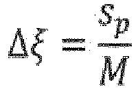
- A third consequence is that in order to compensate for the loss in spatial resolution, and thus in order to ensure that per digital image detector pixel a pixel of both the phase image and the dark field image can be reconstructed, the displacement of the pre-sampling mask Δξ must be equal to the pixel size of the detector sp divided by the magnification M:
- The method relies on a sequence of steps which are initially common to the acquisition of PCI images on a conventional system; as a first step, a series of n conventional x-ray absorption images are acquired for which it is noted that each image is acquired with a slightly different pre-sample mask position. In other words the pre-sample mask is shifted in between the n different exposures so to cover the entire distance of the virtual analyser grating pitch pvg as the sum of the n subsequent steps. The number n may be arbitrarily to some extent, but determined by the number of full detector pixels that are comprised in a measured profile that allows us to reconstruct a single PCI image pixel. Therefore, the number of pixels n should only cover the amount needed to record a meaningful intensity profile for a single beamlet. The number of detector pixels n thus determines the width of the measured profile, but will then also require that the dimensions of the pre-sample mask and the magnification M are adapted to this choice (as explained above). A higher value of n allows a smoother profile measurement for one PCI image pixel, but at the same time reduces the spatial resolution of the image, which can however be compensated by acquiring n acquisitions (the higher the value of n, the more acquisitions are required to achieve the same spatial resolution). In a preferred embodiment the number n equals 4, which can be considered to be the absolute minimum.
- In the further explanation, including the drawings to which reference is made, the number n is chosen to equal 4. However, this is not a limitation for the applicability of this invention.
- The above series of n acquired x-ray absorption images are represented in
Fig. 6 as images I, II, III and IV. For each of these images, it is shown in the drawing that pre-sample mask grating bars (32) are shifted as indicated by the arrows for each of the acquisitions I to IV. Consequently, the radiation profiles also shift to expose a different set of detector pixels (30). Each set of said detector pixels (30) will allow to reconstruct one pixel in the phase and dark field image. - In conventional PCI imaging, a portion of the pixels of the digital image detector would have to be blocked (by the grating bars of the analyser grating) in order to obtain the necessary image data to reconstruct the phase and dark filed images. Typically the re-calculation of the phase image is based on the difference of two images recorded at different positions of the analyser grating. The scatter image typically uses the sum of two normalized images. This means that multiple images need to be acquired for the same pre-sample mask position in order to be able to reconstruct a single phase or dark field image.
- Consequently, in order to achieve the full image detector resolution in the PCI images, a multiple of n more conventional PCI acquisitions would be required. For each pre-sample mask position (n in total) a multiple of radiation profile data would have to be acquired shifting the analyser grating to different positions in order to obtain the desired profile data.
- In a preferred embodiment of the invention, the PCI image profile data are acquired more efficiently using the virtual grating technique. Since no physical analyser grating (or detector grating) is used, there is no need to make real acquisitions for each physical analyser grating movement. Instead, the same digital image that is acquired while being subjected to a certain pre-sample mask position, is processed as such that selected lines (or other configurations) of pixels (which take the place of the position of the conventional grating bars) are omitted or not taken into consideration for reconstruction. As such, a so-called virtual mask is laid over the digital image matrix thereby determining the locations of the image which are considered to be taken into account (or are considered "switched on").
-
Fig. 6 illustrates the pixel modulation that is applied by the virtual grating on each sequence of 4 detector pixels (30). The different pixel modulations (A, B, C and D) are shown for each of the n acquired x-ray absorption images (I, II, III and IV) in the respective columns. The active/inactive pixels are shown with a different shading color. One of the 4 modulations is not used for image reconstruction, as this sequence does not capture any of the pixel values in the center of the radiation profile (this corresponds to a grating bar blocking the central part of the profile). These unused modulations are crossed-out inFig. 6 . - In case that the phase and dark field image would be reconstructed based entirely on the above pixel modulated images (as to mimic the physical grating), the results would be uncorrected for gradient artefacts.
- Alternatively, rather than to perform n consecutive pixel modulations in real-space on each of the n images acquired using different pre-sample mask positions in order to extract the measurement profiles for reconstructing the PCI images as explained above, it is possible to perform the same operation in the Fourier domain after transformation of the n images to the Fourier space. The basis for this is the fact that a periodic image (such as an intensity modulated image by a grating) produces a Fourier transform with a 0-order (that is related to the constant part of the image), a 1st order related to the main frequency of the modulation (i.e. the frequency of the pre-sample mask) and higher orders (harmonics) which are related to multiples of the frequency of the 1st order. Refraction and scatter influence the periodic part of the intensity profile and thus cause changes in the 1st order peak of the Fourier transformation. The complex 2D Fourier transform thus has a characteristic look as shown in
Fig. 9 on which identifiable peaks are visible. - It suffices to filter out the desired portion of this complex 2D (two dimensional) Fourier transform representing the 1st order signal in order to perform the same operation as the virtual grating does in real space. The 2D Fourier transformed image shows 3 identifiable regions (or sub-arrays) centered on 3 clearly identifiable peaks. A first region (50) is centered on the 0th order peak (40) and the region height is defined by the distance (55) (expressed in number of pixels) between the 0th and 1st order peak. The width of this region is defined by the width of the raw image as we use a 1D grating. A second region is centered at the 1st order peak (51) and again the region height is defined by the distance (55) between the 0th and 1st order peak. These identified regions are separated and back transformed (using a complex inverse Fourier transform) and result in 3 images:
- 1- the absorption image is obtained through back transformation of the magnitude of the region (50) centered on the 0th order peak (40),
- 2- the refraction image is obtained through back transformation from the phase data of the back transformed region (51) centered on the 1st order peak (41) (which is in fact an angle in the complex plane),
- 3- the scatter image is obtained from the magnitude of the back transformation of the region (51) centered on the 1st order peak (41) divided by the absorption image.
- Still, the obtained images would be uncorrected for gradient artefacts. As explained before, in order to correct for this type of artefact, the conventional approach (using a physical analyser grating) would be to acquire additional profile data that would allow to normalize a radiation profile with profiles centered on its closest neighbouring pixels. The normalization would be done in the case of our preferred embodiment of 4 pixel-sized sets with the at least 2 neighbouring (left and right) profiles.
- However, we surprisingly found that no additional image acquisitions are required when applying the virtual grating technique; the required normalization profiles are already available in already acquired absorption images. Selecting the correct image data and applying the correct profile data of said image data for normalizing the corresponding PCI image allows to perform the correction without the need for additional acquisitions.
-
Fig. 7 illustrates for our example which profile data should be taken into consideration for the normalisation step of certain a exposure (I, II, III or IV). As can be seen, the profile spanning the full 4 pixels of the pixel set can be used to normalize the profile data used to reconstruct the PCI images. - In a preferred embodiment, the normalization of a certain measured profile is performed by comparing the maximum of this considered measurement profile with the maxima of the profiles centred on its closest neighbouring pixels. A deviation between the considered maximum and the respective neighbouring maxima vouches for the presence of an absorption gradient. The maximum of the measured profile in question can then be adjusted to better align to the values of its neighbours. This alignment is achieved through normalisation, or through any other means of adjustment.
- The recalculation of the phase ph then typically consists of two terms: an uncorrected phase phnc and a correction term c. The terms are functions of the pixel values I 1 & I 2, representing the 2 most central pixels of the set of 4 pixels (refer to
Fig. 7 ).
- The correction factor c depends on the exact geometry of the setup and to some extend also on the absorption and transmission of the pre-sample mask
- The method described above can also be applied to correct scatter image re-calculation. The approach is similar. The main difference is the calculation of the correction factor c. It may also be advantageous to use other pixel values than those of the centred pixels as the absorption gradient impacts the calculation of the scatter image differently (see
fig. 5 ). For someone skilled in the art it is obvious that the absorption gradient correction can be used to correct phase images and to correct scatter images in an almost similar way as the effect on the shape of the intensity profile of a beamlet is similar in both cases. I.e. an absorption gradient shifts and narrows the profile of a beamlet - for phase correction the shift has to be calculated for scatter correction the narrowing has to be calculated.
Claims (9)
- Method for generating a high-resolution PCI image corrected for absorption gradient artefacts on a PCI system,
comprising the steps of:- acquiring a series of n ≥4 x-ray absorption images on an x-ray detector, acquiring said x-ray absorption images at n different positions ξ 1→n of a pre-sample mask in said PCI system, wherein - computing n uncorrected PCI images for each of said n x-ray absorption images, each uncorrected PCI image being calculated from n different sets of the total number of pixels detected by said x-ray detector, said n sets being obtained by virtually overlaying the pixel matrix read out of the exposed detector by a virtual mask having on/off locations and by using pixels covered by 'on' locations of the virtual mask to populate a first set and shifting said virtual mask relative to the pixel matrix to obtain further sets;- calculating n corrected PCI images by correcting respective phase and scatter profile measurements at each detector position of said n uncorrected PCI images by normalizing said uncorrected profile measurement with at least 2 acquired profile measurements from directly neighbouring pre-sample mask positions and corresponding detector pixels, said profile measurements from directly neighbouring pre-sample mask positions obtainable from the corresponding neighbouring image from the series of n x-ray absorption images,- recombining said n corrected phase contrast images into a high-resolution PCI image, wherein each same pixel position values of said n corrected PCI images are collated into n consecutive pixels of the recombined high-resolution PCI image.
 - The method according to Claim 1, wherein said PCI image is a phase image or a dark field image.
- The method according to Claim 1, wherein the value of n is 4, 6 or 8.
- The method according to Claim 1, where the normalization of the uncorrected profile measurements is done by comparing direct pixel values of the X-ray detector.
- The method according to Claim 1, where the normalization of the uncorrected profile measurements is done by comparing the logarithms of pixel values of the X-ray detector.
- Method for generating a high-resolution PCI image corrected for absorption gradient artefacts on a PCI system,
comprising the steps of:- acquiring a series of n ≥4 x-ray absorption images on an x-ray detector, acquiring said x-ray absorption images at n different positions ξ 1→n of a pre-sample mask in said PCI system, wherein - computing n uncorrected PCI images for each of said n x-ray absorption images, each uncorrected PCI image being calculated from a Fourier transformation of the detector data followed by selecting a sub-set of the Fourier transformed image and a back-transformation of said selected sub-set,- calculating n corrected PCI images by correcting the respective phase and scatter profile measurements at each detector position of said n uncorrected PCI images by normalizing said uncorrected profile measurement with at least 2 acquired profile measurements from directly neighbouring pre-sample mask positions and corresponding detector pixels, said profile measurements from directly neighbouring pre-sample mask positions obtainable from the corresponding neighbouring image from the series of n x-ray absorption images,- recombining said n corrected phase contrast images into a high-resolution PCI image, wherein each same pixel position values of said n corrected PCI images are collated into n consecutive pixels of the recombined high-resolution PCI image.
 - The method according to Claim 6 wherein the sub-set of the Fourier transformed image is defined as the rectangular region centered on the 0th or the 1st order peak of said image, and wherein the region height is defined by the distance between the 0th and 1st order peak, and the region width is defined by the width of the image.
- The method according to Claim 6 or 7, wherein a corrected PCI image is obtained through normalization of said uncorrected PCI image followed by the calculation from a Fourier transformation of the detector data, selecting a sub-set of the Fourier transformed image and a back-transformation of said selected sub-set.
- The method according to Claim 6, where the uncorrected profile calculation is based on a Fourier transformation and correction is applied after the transformations by normalization using a second and third Fourier transformation and back-transformation of sub-regions to acquire the correction data.
Priority Applications (1)
| Application Number | Priority Date | Filing Date | Title |
|---|---|---|---|
| EP18180185.3A EP3588428B1 (en) | 2018-06-27 | 2018-06-27 | Pci correction |
Applications Claiming Priority (1)
| Application Number | Priority Date | Filing Date | Title |
|---|---|---|---|
| EP18180185.3A EP3588428B1 (en) | 2018-06-27 | 2018-06-27 | Pci correction |
Publications (2)
| Publication Number | Publication Date |
|---|---|
| EP3588428A1 true EP3588428A1 (en) | 2020-01-01 |
| EP3588428B1 EP3588428B1 (en) | 2023-06-07 |
Family
ID=62841838
Family Applications (1)
| Application Number | Title | Priority Date | Filing Date |
|---|---|---|---|
| EP18180185.3A Active EP3588428B1 (en) | 2018-06-27 | 2018-06-27 | Pci correction |
Country Status (1)
| Country | Link |
|---|---|
| EP (1) | EP3588428B1 (en) |
Citations (3)
| Publication number | Priority date | Publication date | Assignee | Title |
|---|---|---|---|---|
| WO2017015381A1 (en) * | 2015-07-20 | 2017-01-26 | Rensselaer Polytechnic Institute | X-ray phase-contrast and dark-field information extraction with electric fringe scanning and/or active pixel processing |
| US20170307549A1 (en) * | 2016-04-18 | 2017-10-26 | The Board Of Trustees Of The Leland Stanford Junior University | Single X-ray Grating X-ray Differential Phase Contrast Imaging System |
| US9805481B2 (en) * | 2016-01-22 | 2017-10-31 | General Electric Company | System and method for regularized reconstruction of phase contrast computerized tomography |
-
2018
- 2018-06-27 EP EP18180185.3A patent/EP3588428B1/en active Active
Patent Citations (3)
| Publication number | Priority date | Publication date | Assignee | Title |
|---|---|---|---|---|
| WO2017015381A1 (en) * | 2015-07-20 | 2017-01-26 | Rensselaer Polytechnic Institute | X-ray phase-contrast and dark-field information extraction with electric fringe scanning and/or active pixel processing |
| US9805481B2 (en) * | 2016-01-22 | 2017-10-31 | General Electric Company | System and method for regularized reconstruction of phase contrast computerized tomography |
| US20170307549A1 (en) * | 2016-04-18 | 2017-10-26 | The Board Of Trustees Of The Leland Stanford Junior University | Single X-ray Grating X-ray Differential Phase Contrast Imaging System |
Non-Patent Citations (2)
| Title |
|---|
| FABIO DE MARCO ET AL: "Analysis and correction of bias induced by phase stepping jitter in grating-based X-ray phase-contrast imaging", OPTICS EXPRESS, vol. 26, no. 10, 3 May 2018 (2018-05-03), pages 12707, XP055525512, DOI: 10.1364/OE.26.012707 * |
| KREJCI F ET AL: "Single grating method for low dose 1-D and 2-D phase contrast X-ray imaging", JOURNAL OF INSTRUMENTATION, INSTITUTE OF PHYSICS PUBLISHING, BRISTOL, GB, vol. 6, no. 1, 11 January 2011 (2011-01-11), pages C01073, XP020203529, ISSN: 1748-0221, DOI: 10.1088/1748-0221/6/01/C01073 * |
Also Published As
| Publication number | Publication date |
|---|---|
| EP3588428B1 (en) | 2023-06-07 |
Similar Documents
| Publication | Publication Date | Title |
|---|---|---|
| US9795350B2 (en) | Material differentiation with phase contrast imaging | |
| RU2545319C2 (en) | Phase-contrast image formation | |
| Raupach et al. | Analytical evaluation of the signal and noise propagation in x-ray differential phase-contrast computed tomography | |
| JP6214819B1 (en) | Optimal energy weighting of dark field signals in differential phase contrast X-ray imaging | |
| JP5955846B2 (en) | Normalized phase recovery in differential phase contrast imaging | |
| EP2442722B1 (en) | Correction method for differential phase contrast imaging | |
| EP2060909B1 (en) | Interferometer device and method | |
| US9907524B2 (en) | Material decomposition technique using x-ray phase contrast imaging system | |
| US8989347B2 (en) | Image reconstruction method for differential phase contrast X-ray imaging | |
| US10339674B2 (en) | Quantitative dark-field imaging in tomography | |
| CN113678025B (en) | Coaxial X-ray focusing optics for manipulating X-rays in medical transmission radiography | |
| US20170213364A1 (en) | System and method for regularized reconstruction of phase contrast computerized tomography | |
| US12272036B2 (en) | System and method for correcting motion artifacts by combining images in phase-contrast and dark-field imaging applications | |
| EP3435325A1 (en) | Scatter correction for dark field imaging | |
| US12266162B2 (en) | Enhancing contrast sensitivity and resolution in a grating interferometer by machine learning | |
| US7519143B2 (en) | Method and system for generating a scatter corrected X-ray image | |
| EP3588428B1 (en) | Pci correction | |
| EP3998948B1 (en) | Apparatus for processing data acquired by a dark-field and/or phase contrast x-ray imaging system | |
| US20250225782A1 (en) | Enhancing contrast sensitivity and resolution in a grating interferometer by machine learning | |
| Mittone | Development of X-ray phase-contrast imaging techniques for medical diagnostics: towards clinical application | |
| Stockdill et al. | Propagation-based X-ray Phase-contrast and Dark-field Imaging for Microstructure Decomposition | |
| Schick | Image Reconstruction Algorithms for the Clinical Prototype Dark-field Scanning System at the Technical University of Munich | |
| WO2021249802A1 (en) | Apparatus for correction of collimator penumbra in an x-ray image |
Legal Events
| Date | Code | Title | Description |
|---|---|---|---|
| PUAI | Public reference made under article 153(3) epc to a published international application that has entered the european phase |
Free format text: ORIGINAL CODE: 0009012 |
|
| STAA | Information on the status of an ep patent application or granted ep patent |
Free format text: STATUS: THE APPLICATION HAS BEEN PUBLISHED |
|
| AK | Designated contracting states |
Kind code of ref document: A1 Designated state(s): AL AT BE BG CH CY CZ DE DK EE ES FI FR GB GR HR HU IE IS IT LI LT LU LV MC MK MT NL NO PL PT RO RS SE SI SK SM TR |
|
| AX | Request for extension of the european patent |
Extension state: BA ME |
|
| STAA | Information on the status of an ep patent application or granted ep patent |
Free format text: STATUS: REQUEST FOR EXAMINATION WAS MADE |
|
| 17P | Request for examination filed |
Effective date: 20200701 |
|
| RBV | Designated contracting states (corrected) |
Designated state(s): AL AT BE BG CH CY CZ DE DK EE ES FI FR GB GR HR HU IE IS IT LI LT LU LV MC MK MT NL NO PL PT RO RS SE SI SK SM TR |
|
| STAA | Information on the status of an ep patent application or granted ep patent |
Free format text: STATUS: EXAMINATION IS IN PROGRESS |
|
| 17Q | First examination report despatched |
Effective date: 20220117 |
|
| GRAP | Despatch of communication of intention to grant a patent |
Free format text: ORIGINAL CODE: EPIDOSNIGR1 |
|
| STAA | Information on the status of an ep patent application or granted ep patent |
Free format text: STATUS: GRANT OF PATENT IS INTENDED |
|
| INTG | Intention to grant announced |
Effective date: 20230306 |
|
| GRAS | Grant fee paid |
Free format text: ORIGINAL CODE: EPIDOSNIGR3 |
|
| GRAA | (expected) grant |
Free format text: ORIGINAL CODE: 0009210 |
|
| STAA | Information on the status of an ep patent application or granted ep patent |
Free format text: STATUS: THE PATENT HAS BEEN GRANTED |
|
| AK | Designated contracting states |
Kind code of ref document: B1 Designated state(s): AL AT BE BG CH CY CZ DE DK EE ES FI FR GB GR HR HU IE IS IT LI LT LU LV MC MK MT NL NO PL PT RO RS SE SI SK SM TR |
|
| REG | Reference to a national code |
Ref country code: GB Ref legal event code: FG4D |
|
| REG | Reference to a national code |
Ref country code: CH Ref legal event code: EP Ref country code: AT Ref legal event code: REF Ref document number: 1577257 Country of ref document: AT Kind code of ref document: T Effective date: 20230615 |
|
| REG | Reference to a national code |
Ref country code: DE Ref legal event code: R096 Ref document number: 602018050711 Country of ref document: DE |
|
| PGFP | Annual fee paid to national office [announced via postgrant information from national office to epo] |
Ref country code: FR Payment date: 20230530 Year of fee payment: 6 Ref country code: DE Payment date: 20230531 Year of fee payment: 6 |
|
| REG | Reference to a national code |
Ref country code: LT Ref legal event code: MG9D |
|
| REG | Reference to a national code |
Ref country code: NL Ref legal event code: MP Effective date: 20230607 |
|
| PG25 | Lapsed in a contracting state [announced via postgrant information from national office to epo] |
Ref country code: SE Free format text: LAPSE BECAUSE OF FAILURE TO SUBMIT A TRANSLATION OF THE DESCRIPTION OR TO PAY THE FEE WITHIN THE PRESCRIBED TIME-LIMIT Effective date: 20230607 Ref country code: NO Free format text: LAPSE BECAUSE OF FAILURE TO SUBMIT A TRANSLATION OF THE DESCRIPTION OR TO PAY THE FEE WITHIN THE PRESCRIBED TIME-LIMIT Effective date: 20230907 Ref country code: ES Free format text: LAPSE BECAUSE OF FAILURE TO SUBMIT A TRANSLATION OF THE DESCRIPTION OR TO PAY THE FEE WITHIN THE PRESCRIBED TIME-LIMIT Effective date: 20230607 |
|
| PGFP | Annual fee paid to national office [announced via postgrant information from national office to epo] |
Ref country code: GB Payment date: 20230608 Year of fee payment: 6 |
|
| REG | Reference to a national code |
Ref country code: AT Ref legal event code: MK05 Ref document number: 1577257 Country of ref document: AT Kind code of ref document: T Effective date: 20230607 |
|
| PG25 | Lapsed in a contracting state [announced via postgrant information from national office to epo] |
Ref country code: RS Free format text: LAPSE BECAUSE OF FAILURE TO SUBMIT A TRANSLATION OF THE DESCRIPTION OR TO PAY THE FEE WITHIN THE PRESCRIBED TIME-LIMIT Effective date: 20230607 Ref country code: NL Free format text: LAPSE BECAUSE OF FAILURE TO SUBMIT A TRANSLATION OF THE DESCRIPTION OR TO PAY THE FEE WITHIN THE PRESCRIBED TIME-LIMIT Effective date: 20230607 Ref country code: LV Free format text: LAPSE BECAUSE OF FAILURE TO SUBMIT A TRANSLATION OF THE DESCRIPTION OR TO PAY THE FEE WITHIN THE PRESCRIBED TIME-LIMIT Effective date: 20230607 Ref country code: LT Free format text: LAPSE BECAUSE OF FAILURE TO SUBMIT A TRANSLATION OF THE DESCRIPTION OR TO PAY THE FEE WITHIN THE PRESCRIBED TIME-LIMIT Effective date: 20230607 Ref country code: HR Free format text: LAPSE BECAUSE OF FAILURE TO SUBMIT A TRANSLATION OF THE DESCRIPTION OR TO PAY THE FEE WITHIN THE PRESCRIBED TIME-LIMIT Effective date: 20230607 Ref country code: GR Free format text: LAPSE BECAUSE OF FAILURE TO SUBMIT A TRANSLATION OF THE DESCRIPTION OR TO PAY THE FEE WITHIN THE PRESCRIBED TIME-LIMIT Effective date: 20230908 |
|
| PG25 | Lapsed in a contracting state [announced via postgrant information from national office to epo] |
Ref country code: FI Free format text: LAPSE BECAUSE OF FAILURE TO SUBMIT A TRANSLATION OF THE DESCRIPTION OR TO PAY THE FEE WITHIN THE PRESCRIBED TIME-LIMIT Effective date: 20230607 |
|
| PG25 | Lapsed in a contracting state [announced via postgrant information from national office to epo] |
Ref country code: SK Free format text: LAPSE BECAUSE OF FAILURE TO SUBMIT A TRANSLATION OF THE DESCRIPTION OR TO PAY THE FEE WITHIN THE PRESCRIBED TIME-LIMIT Effective date: 20230607 |
|
| PG25 | Lapsed in a contracting state [announced via postgrant information from national office to epo] |
Ref country code: IS Free format text: LAPSE BECAUSE OF FAILURE TO SUBMIT A TRANSLATION OF THE DESCRIPTION OR TO PAY THE FEE WITHIN THE PRESCRIBED TIME-LIMIT Effective date: 20231007 |
|
| PG25 | Lapsed in a contracting state [announced via postgrant information from national office to epo] |
Ref country code: SM Free format text: LAPSE BECAUSE OF FAILURE TO SUBMIT A TRANSLATION OF THE DESCRIPTION OR TO PAY THE FEE WITHIN THE PRESCRIBED TIME-LIMIT Effective date: 20230607 Ref country code: SK Free format text: LAPSE BECAUSE OF FAILURE TO SUBMIT A TRANSLATION OF THE DESCRIPTION OR TO PAY THE FEE WITHIN THE PRESCRIBED TIME-LIMIT Effective date: 20230607 Ref country code: RO Free format text: LAPSE BECAUSE OF FAILURE TO SUBMIT A TRANSLATION OF THE DESCRIPTION OR TO PAY THE FEE WITHIN THE PRESCRIBED TIME-LIMIT Effective date: 20230607 Ref country code: PT Free format text: LAPSE BECAUSE OF FAILURE TO SUBMIT A TRANSLATION OF THE DESCRIPTION OR TO PAY THE FEE WITHIN THE PRESCRIBED TIME-LIMIT Effective date: 20231009 Ref country code: IS Free format text: LAPSE BECAUSE OF FAILURE TO SUBMIT A TRANSLATION OF THE DESCRIPTION OR TO PAY THE FEE WITHIN THE PRESCRIBED TIME-LIMIT Effective date: 20231007 Ref country code: EE Free format text: LAPSE BECAUSE OF FAILURE TO SUBMIT A TRANSLATION OF THE DESCRIPTION OR TO PAY THE FEE WITHIN THE PRESCRIBED TIME-LIMIT Effective date: 20230607 Ref country code: CZ Free format text: LAPSE BECAUSE OF FAILURE TO SUBMIT A TRANSLATION OF THE DESCRIPTION OR TO PAY THE FEE WITHIN THE PRESCRIBED TIME-LIMIT Effective date: 20230607 Ref country code: AT Free format text: LAPSE BECAUSE OF FAILURE TO SUBMIT A TRANSLATION OF THE DESCRIPTION OR TO PAY THE FEE WITHIN THE PRESCRIBED TIME-LIMIT Effective date: 20230607 |
|
| REG | Reference to a national code |
Ref country code: CH Ref legal event code: PL |
|
| REG | Reference to a national code |
Ref country code: BE Ref legal event code: MM Effective date: 20230630 |
|
| PG25 | Lapsed in a contracting state [announced via postgrant information from national office to epo] |
Ref country code: PL Free format text: LAPSE BECAUSE OF FAILURE TO SUBMIT A TRANSLATION OF THE DESCRIPTION OR TO PAY THE FEE WITHIN THE PRESCRIBED TIME-LIMIT Effective date: 20230607 |
|
| PG25 | Lapsed in a contracting state [announced via postgrant information from national office to epo] |
Ref country code: LU Free format text: LAPSE BECAUSE OF NON-PAYMENT OF DUE FEES Effective date: 20230627 |
|
| REG | Reference to a national code |
Ref country code: DE Ref legal event code: R097 Ref document number: 602018050711 Country of ref document: DE |
|
| PG25 | Lapsed in a contracting state [announced via postgrant information from national office to epo] |
Ref country code: MC Free format text: LAPSE BECAUSE OF FAILURE TO SUBMIT A TRANSLATION OF THE DESCRIPTION OR TO PAY THE FEE WITHIN THE PRESCRIBED TIME-LIMIT Effective date: 20230607 |
|
| REG | Reference to a national code |
Ref country code: IE Ref legal event code: MM4A |
|
| PG25 | Lapsed in a contracting state [announced via postgrant information from national office to epo] |
Ref country code: MC Free format text: LAPSE BECAUSE OF FAILURE TO SUBMIT A TRANSLATION OF THE DESCRIPTION OR TO PAY THE FEE WITHIN THE PRESCRIBED TIME-LIMIT Effective date: 20230607 Ref country code: LU Free format text: LAPSE BECAUSE OF NON-PAYMENT OF DUE FEES Effective date: 20230627 |
|
| PLBE | No opposition filed within time limit |
Free format text: ORIGINAL CODE: 0009261 |
|
| STAA | Information on the status of an ep patent application or granted ep patent |
Free format text: STATUS: NO OPPOSITION FILED WITHIN TIME LIMIT |
|
| PG25 | Lapsed in a contracting state [announced via postgrant information from national office to epo] |
Ref country code: IE Free format text: LAPSE BECAUSE OF NON-PAYMENT OF DUE FEES Effective date: 20230627 |
|
| PG25 | Lapsed in a contracting state [announced via postgrant information from national office to epo] |
Ref country code: IE Free format text: LAPSE BECAUSE OF NON-PAYMENT OF DUE FEES Effective date: 20230627 Ref country code: DK Free format text: LAPSE BECAUSE OF FAILURE TO SUBMIT A TRANSLATION OF THE DESCRIPTION OR TO PAY THE FEE WITHIN THE PRESCRIBED TIME-LIMIT Effective date: 20230607 Ref country code: CH Free format text: LAPSE BECAUSE OF NON-PAYMENT OF DUE FEES Effective date: 20230630 |
|
| PG25 | Lapsed in a contracting state [announced via postgrant information from national office to epo] |
Ref country code: SI Free format text: LAPSE BECAUSE OF FAILURE TO SUBMIT A TRANSLATION OF THE DESCRIPTION OR TO PAY THE FEE WITHIN THE PRESCRIBED TIME-LIMIT Effective date: 20230607 |
|
| 26N | No opposition filed |
Effective date: 20240308 |
|
| PG25 | Lapsed in a contracting state [announced via postgrant information from national office to epo] |
Ref country code: SI Free format text: LAPSE BECAUSE OF FAILURE TO SUBMIT A TRANSLATION OF THE DESCRIPTION OR TO PAY THE FEE WITHIN THE PRESCRIBED TIME-LIMIT Effective date: 20230607 Ref country code: IT Free format text: LAPSE BECAUSE OF FAILURE TO SUBMIT A TRANSLATION OF THE DESCRIPTION OR TO PAY THE FEE WITHIN THE PRESCRIBED TIME-LIMIT Effective date: 20230607 Ref country code: BE Free format text: LAPSE BECAUSE OF NON-PAYMENT OF DUE FEES Effective date: 20230630 |
|
| PG25 | Lapsed in a contracting state [announced via postgrant information from national office to epo] |
Ref country code: BG Free format text: LAPSE BECAUSE OF FAILURE TO SUBMIT A TRANSLATION OF THE DESCRIPTION OR TO PAY THE FEE WITHIN THE PRESCRIBED TIME-LIMIT Effective date: 20230607 |
|
| PG25 | Lapsed in a contracting state [announced via postgrant information from national office to epo] |
Ref country code: BG Free format text: LAPSE BECAUSE OF FAILURE TO SUBMIT A TRANSLATION OF THE DESCRIPTION OR TO PAY THE FEE WITHIN THE PRESCRIBED TIME-LIMIT Effective date: 20230607 |
|
| REG | Reference to a national code |
Ref country code: DE Ref legal event code: R119 Ref document number: 602018050711 Country of ref document: DE |
|
| GBPC | Gb: european patent ceased through non-payment of renewal fee |
Effective date: 20240627 |
|
| PG25 | Lapsed in a contracting state [announced via postgrant information from national office to epo] |
Ref country code: DE Free format text: LAPSE BECAUSE OF NON-PAYMENT OF DUE FEES Effective date: 20250101 |
|
| PG25 | Lapsed in a contracting state [announced via postgrant information from national office to epo] |
Ref country code: FR Free format text: LAPSE BECAUSE OF NON-PAYMENT OF DUE FEES Effective date: 20240630 |
|
| PG25 | Lapsed in a contracting state [announced via postgrant information from national office to epo] |
Ref country code: GB Free format text: LAPSE BECAUSE OF NON-PAYMENT OF DUE FEES Effective date: 20240627 |
|
| PG25 | Lapsed in a contracting state [announced via postgrant information from national office to epo] |
Ref country code: CY Free format text: LAPSE BECAUSE OF FAILURE TO SUBMIT A TRANSLATION OF THE DESCRIPTION OR TO PAY THE FEE WITHIN THE PRESCRIBED TIME-LIMIT; INVALID AB INITIO Effective date: 20180627 |
|
| PG25 | Lapsed in a contracting state [announced via postgrant information from national office to epo] |
Ref country code: HU Free format text: LAPSE BECAUSE OF FAILURE TO SUBMIT A TRANSLATION OF THE DESCRIPTION OR TO PAY THE FEE WITHIN THE PRESCRIBED TIME-LIMIT; INVALID AB INITIO Effective date: 20180627 |
|
| PG25 | Lapsed in a contracting state [announced via postgrant information from national office to epo] |
Ref country code: TR Free format text: LAPSE BECAUSE OF FAILURE TO SUBMIT A TRANSLATION OF THE DESCRIPTION OR TO PAY THE FEE WITHIN THE PRESCRIBED TIME-LIMIT Effective date: 20230607 |