EP3588402A1 - Aircraft management system - Google Patents
Aircraft management system Download PDFInfo
- Publication number
- EP3588402A1 EP3588402A1 EP19172193.5A EP19172193A EP3588402A1 EP 3588402 A1 EP3588402 A1 EP 3588402A1 EP 19172193 A EP19172193 A EP 19172193A EP 3588402 A1 EP3588402 A1 EP 3588402A1
- Authority
- EP
- European Patent Office
- Prior art keywords
- aircraft
- inventory
- diagnosis
- request signal
- optical fiber
- Prior art date
- Legal status (The legal status is an assumption and is not a legal conclusion. Google has not performed a legal analysis and makes no representation as to the accuracy of the status listed.)
- Withdrawn
Links
Images


Classifications
-
- B—PERFORMING OPERATIONS; TRANSPORTING
- B64—AIRCRAFT; AVIATION; COSMONAUTICS
- B64F—GROUND OR AIRCRAFT-CARRIER-DECK INSTALLATIONS SPECIALLY ADAPTED FOR USE IN CONNECTION WITH AIRCRAFT; DESIGNING, MANUFACTURING, ASSEMBLING, CLEANING, MAINTAINING OR REPAIRING AIRCRAFT, NOT OTHERWISE PROVIDED FOR; HANDLING, TRANSPORTING, TESTING OR INSPECTING AIRCRAFT COMPONENTS, NOT OTHERWISE PROVIDED FOR
- B64F5/00—Designing, manufacturing, assembling, cleaning, maintaining or repairing aircraft, not otherwise provided for; Handling, transporting, testing or inspecting aircraft components, not otherwise provided for
- B64F5/60—Testing or inspecting aircraft components or systems
-
- B—PERFORMING OPERATIONS; TRANSPORTING
- B64—AIRCRAFT; AVIATION; COSMONAUTICS
- B64F—GROUND OR AIRCRAFT-CARRIER-DECK INSTALLATIONS SPECIALLY ADAPTED FOR USE IN CONNECTION WITH AIRCRAFT; DESIGNING, MANUFACTURING, ASSEMBLING, CLEANING, MAINTAINING OR REPAIRING AIRCRAFT, NOT OTHERWISE PROVIDED FOR; HANDLING, TRANSPORTING, TESTING OR INSPECTING AIRCRAFT COMPONENTS, NOT OTHERWISE PROVIDED FOR
- B64F5/00—Designing, manufacturing, assembling, cleaning, maintaining or repairing aircraft, not otherwise provided for; Handling, transporting, testing or inspecting aircraft components, not otherwise provided for
- B64F5/40—Maintaining or repairing aircraft
-
- G—PHYSICS
- G06—COMPUTING OR CALCULATING; COUNTING
- G06Q—INFORMATION AND COMMUNICATION TECHNOLOGY [ICT] SPECIALLY ADAPTED FOR ADMINISTRATIVE, COMMERCIAL, FINANCIAL, MANAGERIAL OR SUPERVISORY PURPOSES; SYSTEMS OR METHODS SPECIALLY ADAPTED FOR ADMINISTRATIVE, COMMERCIAL, FINANCIAL, MANAGERIAL OR SUPERVISORY PURPOSES, NOT OTHERWISE PROVIDED FOR
- G06Q10/00—Administration; Management
- G06Q10/06—Resources, workflows, human or project management; Enterprise or organisation planning; Enterprise or organisation modelling
-
- G—PHYSICS
- G06—COMPUTING OR CALCULATING; COUNTING
- G06Q—INFORMATION AND COMMUNICATION TECHNOLOGY [ICT] SPECIALLY ADAPTED FOR ADMINISTRATIVE, COMMERCIAL, FINANCIAL, MANAGERIAL OR SUPERVISORY PURPOSES; SYSTEMS OR METHODS SPECIALLY ADAPTED FOR ADMINISTRATIVE, COMMERCIAL, FINANCIAL, MANAGERIAL OR SUPERVISORY PURPOSES, NOT OTHERWISE PROVIDED FOR
- G06Q10/00—Administration; Management
- G06Q10/08—Logistics, e.g. warehousing, loading or distribution; Inventory or stock management
-
- G—PHYSICS
- G06—COMPUTING OR CALCULATING; COUNTING
- G06Q—INFORMATION AND COMMUNICATION TECHNOLOGY [ICT] SPECIALLY ADAPTED FOR ADMINISTRATIVE, COMMERCIAL, FINANCIAL, MANAGERIAL OR SUPERVISORY PURPOSES; SYSTEMS OR METHODS SPECIALLY ADAPTED FOR ADMINISTRATIVE, COMMERCIAL, FINANCIAL, MANAGERIAL OR SUPERVISORY PURPOSES, NOT OTHERWISE PROVIDED FOR
- G06Q10/00—Administration; Management
- G06Q10/08—Logistics, e.g. warehousing, loading or distribution; Inventory or stock management
- G06Q10/087—Inventory or stock management, e.g. order filling, procurement or balancing against orders
- G06Q10/0875—Itemisation or classification of parts, supplies or services, e.g. bill of materials
-
- G—PHYSICS
- G06—COMPUTING OR CALCULATING; COUNTING
- G06Q—INFORMATION AND COMMUNICATION TECHNOLOGY [ICT] SPECIALLY ADAPTED FOR ADMINISTRATIVE, COMMERCIAL, FINANCIAL, MANAGERIAL OR SUPERVISORY PURPOSES; SYSTEMS OR METHODS SPECIALLY ADAPTED FOR ADMINISTRATIVE, COMMERCIAL, FINANCIAL, MANAGERIAL OR SUPERVISORY PURPOSES, NOT OTHERWISE PROVIDED FOR
- G06Q10/00—Administration; Management
- G06Q10/20—Administration of product repair or maintenance
-
- G—PHYSICS
- G06—COMPUTING OR CALCULATING; COUNTING
- G06Q—INFORMATION AND COMMUNICATION TECHNOLOGY [ICT] SPECIALLY ADAPTED FOR ADMINISTRATIVE, COMMERCIAL, FINANCIAL, MANAGERIAL OR SUPERVISORY PURPOSES; SYSTEMS OR METHODS SPECIALLY ADAPTED FOR ADMINISTRATIVE, COMMERCIAL, FINANCIAL, MANAGERIAL OR SUPERVISORY PURPOSES, NOT OTHERWISE PROVIDED FOR
- G06Q30/00—Commerce
- G06Q30/06—Buying, selling or leasing transactions
- G06Q30/0601—Electronic shopping [e-shopping]
- G06Q30/0633—Managing shopping lists, e.g. compiling or processing purchase lists
-
- G—PHYSICS
- G07—CHECKING-DEVICES
- G07C—TIME OR ATTENDANCE REGISTERS; REGISTERING OR INDICATING THE WORKING OF MACHINES; GENERATING RANDOM NUMBERS; VOTING OR LOTTERY APPARATUS; ARRANGEMENTS, SYSTEMS OR APPARATUS FOR CHECKING NOT PROVIDED FOR ELSEWHERE
- G07C5/00—Registering or indicating the working of vehicles
- G07C5/006—Indicating maintenance
Definitions
- the invention relates to an aircraft management system.
- Japanese Unexamined Patent Application Publication JP 2013-193 812 A discloses a technology of deciding quantity of inventory of spare parts used for part replacement, on the basis of operating time and mean time between failures of the parts.
- An aspect of the invention provides an aircraft management system including sensor, a diagnosis, and an outputter.
- the sensor is configured to be loaded onto an aircraft.
- the diagnosis executor is configured to diagnose health of a part of the aircraft on a basis of output from the sensor while the aircraft is flying.
- the outputter is configured to output a request signal requesting a part replacement to an outside of the aircraft through wireless communication, when a replacement of the part is determined to be necessary as a result of diagnosis of the health.
- JP 2013-193 812 A estimates proper quantity of inventory from the mean time between failures.
- the mean time between failures is based on failure records in the past, and inventory shortage occurs if estimation goes wrong. If it takes too much time to procure parts, maintenance may be delayed to exert influence on flight schedules.
- FIG. 1 is a diagram illustrating an aircraft management system 100.
- the aircraft management system 100 includes a diagnosis device 210 and an inventory management server 310.
- the diagnosis device 210 is prepared for each of the aircrafts 200, and loaded onto each of the aircrafts 200.
- the inventory management server 310 is prepared for each airport, for example.
- the diagnosis device 210 communicates with the inventory management server 310 via a wireless communication device 202 loaded onto the aircraft 200, a base station 300, and a communication network 302 (Such as a LAN or the Internet).
- a wireless communication device 202 loaded onto the aircraft 200
- a base station 300 loaded onto the aircraft 200
- a communication network 302 (Such as a LAN or the Internet).
- the diagnosis device 210 will be described first, and then the inventory management server 310 will be described next.
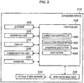
- FIG. 2 is a block diagram illustrating a configuration of the diagnosis device 210.
- the diagnosis device 210 includes a storage 220, an operation unit 222, a display 224, a communication unit 226, a vibrator 228, an optical fiber sensor 230 (sensor), a spectrum analyzer 232, and a controller 234.
- the storage 220 is implemented as RAM, flash memory, an HDD, or the like.
- the operation unit 222 is implemented as a keyboard or a touchscreen that is superimposed on the display 224.
- the operation unit 222 receives operation input from a user.
- the display 224 is implemented as a liquid crystal display, an organic electro-luminescence (EL) display, or the like.
- the communication unit 226 communicates with the wireless communication device 202 loaded onto the aircraft 200 in a wired manner, for example.
- the vibrator 228 is implemented as piezoelectric elements (piezo elements) attached to a sheet.
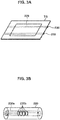
- FIG. 3 is an explanatory diagram illustrating the vibrator 228 and the optical fiber sensors 230.
- FIG. 3A illustrates a target TG to which the vibrator 228 and the optical fiber sensors 230 are attached.
- FIG. 3B illustrates an internal configuration of the optical fiber sensor 230.
- the target TG is a part included in the aircraft 200.
- the number of the targets TG is two or more, and the vibrator 228 and the optical fiber sensors 230 are prepared for each of the targets TG.
- the targets TG are plate-like members is taken as an example.
- the shapes of the targets TG are not limited thereto.
- the vibrator 228 and the optical fiber sensors 230 are attached to (installed on) the target TG in an appropriate manner based on the shape of the target TG.
- the piezoelectric elements of the vibrator 228 are coupled to a conducting wire (not illustrated).
- a voltage is applied to a piezoelectric element via the conducting wire, the thickness of the piezoelectric element changes due to the piezoelectric effect.
- a pulse voltage is applied to any piezoelectric element among the piezoelectric elements, the vicinity of the piezoelectric element to which the voltage is applied gets vibrated in the target TG. In such a way, the vibrator 228 vibrates the target TG.
- the optical fiber sensor 230 is intrinsic. In other words, in the optical fiber sensor 230, the optical fiber itself functions as a sensor element. However, the optical fiber sensor 230 may be an extrinsic optical fiber sensor that causes the optical fiber to function only as an optical transmission line to/from another sensor element. For example, the optical fiber sensor 230 is bonded to the target TG with adhesive.
- a core 230a is installed in the inside of a coating or cladding of the optical fiber sensor 230. Light passes through the core 230a. Light transmitting trough the core 230a toward an outside is reflected by the cladding and returned to the core 230a.
- Grating members 230b are installed in the core 230a.
- the grating members 230b have different refractive indices from the other parts of the core 230a.
- the grating members 230b are installed apart from each other in the axis direction of the optical fiber.
- the grating members 230b cause the refractive indices to change periodically (fiber Bragg grating (FBG)).
- FBG fiber Bragg grating
- broadband spectrum light interferes with a specific wavelength called Bragg wavelength in a direction in which they strengthen each other. In such a way, the grating members 230b reflects only a specific wavelength component in the broadband spectrum light. Light of the other wavelength passes through the grating members 230b.
- the wavelength of reflected light is changed when disturbance is added to the grating members 230b.
- the disturbance added to the grating members 230b is measured by measuring the change in the wavelength of the reflected light.
- the spectrum analyzer 232 illustrated in FIG. 2 is coupled to the optical fiber sensors 230.
- the spectrum analyzer 232 includes a light source and a light receiver.
- the light source emits broad spectrum light, and the broad spectrum light reaches the optical fiber sensors 230.
- the optical fiber sensor 230 reflects a part of the light.
- the light receiver of the spectrum analyzer 232 receives the reflected light.
- the spectrum analyzer 232 detects light intensity distribution in a predetermined wavelength band.
- the spectrum analyzer 232 detects the wavelength of the reflected light received by the light receiver.
- the wavelength detected by the spectrum analyzer 232 is converted from analog to digital by an A/D converter (not illustrated), and output to the controller 234.
- the controller 234 manages and controls the whole diagnosis device 210 by using a semiconductor integrated circuit including a central processing unit (CPU), ROM having a program or the like stored therein, RAM that functions as a work area, and the like.
- the controller 234 also functions as a vibration controller 240, a collection processor 242, a diagnosis executor 244, and an outputter 246.
- the vibration controller 240 applies voltage to the vibrator 228 and causes the vibrator 228 to vibrate the target TG.
- the collection processor 242 measures each of the targets TG by using the optical fiber sensors 230. As described above, the collection processor 242 causes the spectrum analyzer 232 to emit the broad spectrum light and detect the wavelength of reflected light. The collection processor 242 uses the wavelength of the reflected light to measure change in the target TG that is a cause of the disturbance added to the grating members 230b.
- the optical fiber sensor 230 a physical quantity is set in advance.
- the physical quantity is a target of measurement such as distortion (stress) or temperature of the target TG.
- an optical fiber sensor 230 for measuring distortion, an optical fiber sensor 230 for measuring temperature, and the like are installed.
- the collection processor 242 measures distortion of the target TG by using reflected light from the optical fiber sensor 230 for measuring distortion. In addition, the collection processor 242 measures temperature of the target TG by using reflected light from the optical fiber sensor 230 for measuring temperature.
- the collection processor 242 may measure distortion of the target TG by using reflected light from the optical fiber sensor 230 for measuring distortion while the vibration controller 240 is controlling the vibrator 228 and the vibrator 228 is vibrating the target TG.
- the collection processor 242 performs a correction process for collecting measurement data of the targets TG from the optical fiber sensors 230.
- the diagnosis executor 244 performs a health diagnosis process for diagnosing health of the targets TG of the aircraft 200 on the basis of the collected measurement data.
- the collection process and the health diagnosis process are performed at any timing while the aircraft 200 is flying.
- the health of a structure is diagnosed by using the collected measurement data of the targets TG.
- the diagnosis executor 244 uses, as standard data, measurement data obtained when there is no distortion and no deficiency such as a timing immediately after the diagnosis device 210 is loaded onto the aircraft 200.
- the diagnosis executor 244 derives evaluation values by comparing new measurement data with the standard data (by using differences, ratios, or the like between the new measurement data and the standard data). For example, the health is calculated as a low evaluation value when the deficient target TG is detected or when the distortion or the temperature shows an abnormal value, as described above.
- the diagnosis executor 244 determines whether replacement of a part such as the target TG is necessary. For example, the diagnosis executor 244 determines that the part such as the target TG needs to be replaced when the evaluation value is less than a preset threshold.
- the part such as the target TG includes any of the target TG itself and a part constituting a portion of the target TG.
- a type table is registered on the storage 220.
- parts such as the targets TG constituting the aircraft 200 are associated with type information indicating types of the respective parts.
- the diagnosis executor 244 refers to the type table in the storage 220 and specifies the type information of a part that needs replacement.
- the outputter 246 controls the communication unit 226 and outputs a request signal to an outside of the aircraft 200 through wireless communication.
- the request signal is a signal requesting part replacement, and includes type information and quantity of a part that needs replacement.
- the outside of the aircraft 200 is, for example, the inventory management server 310 installed in an airport where the aircraft 200 will arrive next.
- an address of an airport where the aircraft 200 will arrive next in the communication network 302 is registered via the operation unit 222. Therefore, it is possible for the outputter 246 to output a request signal to the registered address.
- names of airports are associated with addresses in the communication network 302.
- the outputter 246 may acquire the address and the name of the airport where the aircraft 200 will arrive next from a controller (not illustrated) of the aircraft 200.
- FIG. 4 is a block diagram illustrating a configuration of the inventory management server 310.
- the inventory management server 310 includes a storage 320, an operation unit 322, a display 324, a communication unit 326, and a controller 328.
- the storage 320 is implemented as RAM, flash memory, an HDD, or the like.
- the operation unit 322 is implemented as a keyboard or a touchscreen that is superimposed on the display 324.
- the operation unit 322 receives operation input from a user.
- the display 324 is implemented as a liquid crystal display, an organic EL display, or the like.
- the communication unit 326 communicates with the diagnosis device 210 via the communication network 302, the base station 300, and the wireless communication device 202 of the aircraft 200.
- the controller 328 manages and controls the whole inventory management server 310 by using a semiconductor integrated circuit including a central processing unit (CPU), ROM having a program or the like stored therein, RAM that functions as a work area, and the like.
- the controller 328 also functions as a communication controller 340, an inventory determiner 342, a display controller 344 (reporter), and an orderer 346.
- the communication controller 340 controls the communication unit 326 and acquires a request signal output from the outputter 246 of the diagnosis device 210.
- the inventory determiner 342 determines whether a spare part (herein after, referred to simply as "the part") of a part determined to need replacement is short in inventory in an airport where the inventory management server 310 is installed (an airport where the aircraft 200 will arrive next).
- the inventory determiner 342 specifies quantity of inventory of a part with the type information indicated by the request signal, from the inventory table.
- the inventory determiner 342 determines that inventory is short. When the quantity of inventory of the part is equal to or greater than the quantity indicated by the request signal, the inventory determiner 342 determines that inventory is not short.
- the display controller 344 causes the display 324 to display (report) that inventory is short.
- the orderer 346 orders the part. For example, the orderer 346 generates, in a preregistered format, data of a purchase order containing a part type (part name) determined to be short in inventory and quantity. The orderer 346 controls the communication unit 326, and transmits the generated data of the purchase order to a part supplier via the communication network 302.
- the orderer 346 may be a function loaded into a device dedicated for ordering parts.
- the inventory determiner 342 outputs type information and shortage quantity of the part determined to be short in inventory to the device dedicated for ordering parts via the communication unit 326.
- the device dedicated for ordering parts generates data of a purchase order, on the basis of the input type information and shortage quantity of the part.
- a result of the health diagnosis process performed while the aircraft 200 is flying is output to the inventory management server 310 through wireless communication.
- the inventory management server 310 can specify inventory shortage of a part to be replaced while the aircraft 200 is flying. Therefore, an order for the part whose inventory is short is placed early, which can suppress delay of maintenance due to shortage of parts.
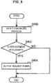
- FIG. 5 is a flowchart illustrating procedure of a process of the diagnosis device 210.
- the process illustrated in FIG. 5 is performed at any timing (for example, is repeated on a predetermined cycle) while the aircraft 200 is flying.
- the diagnosis executor 244 performs the health diagnosis process for diagnosing health of a target TG of an aircraft 200 on the basis of measurement data collected by the collection processor 242.
- the diagnosis executor 244 determines whether the replacement is necessary for the part such as the target TG.
- the process proceeds to Step S404 when it is determined that the part replacement is necessary (YES in Step S402).
- the process ends when it is determined that the part replacement is not necessary (NO in Step S402).
- the outputter 246 controls the communication unit 226, and outputs a request signal to the inventory management server 310 installed in an airport where the aircraft 200 will arrive next through wireless communication.
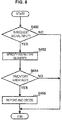
- FIG. 6 is a flowchart illustrating procedure of a process of the inventory management server 310. The process illustrated in FIG. 6 is repeated on a predetermined cycle, for example.
- the inventory determiner 342 determines whether the request signal is input from the communication unit 326. The process proceeds to Step S452 in the case where the request signal is input (YES in Step S450). The process ends in the case where the request signal is not input (NO in Step S450).
- the inventory determiner 342 specifies quantity of inventory of a part with the type information indicated by the request signal, from an inventory table in the storage 320.
- the inventory determiner 342 determines whether inventory is short, i.e., whether the quantity of inventory of the part is smaller than the quantity indicated by the request signal. In the case of inventory shortage (YES in S454), the process proceeds to S456. In the case of no inventory shortage (NO in S454), the process ends.
- the display controller 344 causes the display 324 to display (report) that the part with the type information indicated by the request signal is short in inventory.
- the orderer 346 orders the part with the type information indicated by the request signal.
- the vibrator 228 and the optical fiber sensors 230 have been used as examples. However, it is possible to use other sensors.
- the vibrator 228 is not an essential structural element.
- the fiber Bragg grating optical fiber sensors 230 have been used as examples.
- optical fiber sensors 230 of another type. It is possible to measure a physical quantity or a chemical quantity of a target TG by using not change in wavelength of light but change in other characteristics (intensity, phase, frequency, or polarized wave).
- the outputter 246 outputs a request signal to an address of the inventory management server 310 of an airport where the aircraft 200 will arrive next.
- the outputter 246 outputs a request signal to an address of the inventory management server 310 of an airport where the aircraft 200 will arrive next.
- the outputter 246 may output a request signal to the integrated server. Then, the integrated server may determine inventory shortage in the maintenance factory of the airport where the aircraft 200 will arrive next.
- a worker may acquire a request signal via a terminal, and operate the operation unit 322 of the inventory management server 310 to determine inventory shortage of a part with type information indicated by the request signal.
- the display controller 344 functions as a reporter.
- the worker can check inventory shortage via the display 324.
- the display controller 344 need not function as a reporter.
- inventory shortage may be reported by sound, light emission of a dedicated lamp, or the like, as well as display on the display 324.
- the orderer 346 is installed.
- the orderer 346 automatically orders a part whose inventory is short; thus, forgetting to place an order is avoided.
- the orderer 346 is not an essential structural element.
Landscapes
- Business, Economics & Management (AREA)
- Engineering & Computer Science (AREA)
- Economics (AREA)
- Human Resources & Organizations (AREA)
- General Physics & Mathematics (AREA)
- Physics & Mathematics (AREA)
- Strategic Management (AREA)
- Theoretical Computer Science (AREA)
- General Business, Economics & Management (AREA)
- Marketing (AREA)
- Entrepreneurship & Innovation (AREA)
- Tourism & Hospitality (AREA)
- Quality & Reliability (AREA)
- Operations Research (AREA)
- Development Economics (AREA)
- Finance (AREA)
- Accounting & Taxation (AREA)
- Manufacturing & Machinery (AREA)
- Transportation (AREA)
- Aviation & Aerospace Engineering (AREA)
- Educational Administration (AREA)
- Game Theory and Decision Science (AREA)
- Management, Administration, Business Operations System, And Electronic Commerce (AREA)
- Arrangements For Transmission Of Measured Signals (AREA)
Abstract
Description
- The present application claims priority from Japanese Patent Application
JP 2018-124 160 A filed on June 29, 2018 - The invention relates to an aircraft management system.
- An aircraft is inspected and maintained while being at an airport. At this time, part replacement is performed as needed. For example, Japanese Unexamined Patent Application Publication
JP 2013-193 812 A - An aspect of the invention provides an aircraft management system including sensor, a diagnosis, and an outputter. The sensor is configured to be loaded onto an aircraft. The diagnosis executor is configured to diagnose health of a part of the aircraft on a basis of output from the sensor while the aircraft is flying.
- The outputter is configured to output a request signal requesting a part replacement to an outside of the aircraft through wireless communication, when a replacement of the part is determined to be necessary as a result of diagnosis of the health.
- The accompanying drawings are included to provide a further understanding of the invention and are incorporated in and constitute a part of this specification. The drawings illustrate example embodiments and, together with the specification, serve to explain the principles of the invention.
- FIG. 1
- is a diagram illustrating an aircraft management system;
- FIG. 2
- is a block diagram illustrating a configuration of a diagnosis device;
- FIG. 3
- is an explanatory diagram of a vibrator and optical fiber sensors;
- FIG. 4
- is a block diagram illustrating a configuration of an inventory management server;
- FIG. 5
- is a flowchart illustrating procedure of a process of the diagnosis device; and
- FIG. 6
- is a flowchart illustrating procedure of a process of the inventory management server.
- In the following, some embodiments of the invention are described in detail with reference to the accompanying drawings. Note that sizes, materials, specific values, and any other factors illustrated in respective embodiments are illustrative for easier understanding of the invention, and are not intended to limit the scope of the invention unless otherwise specifically stated. Further, elements in the following example embodiments which are not recited in a most-generic independent claim of the invention are optional and may be provided on an as-needed basis.
- Throughout the present specification and the drawings, elements having substantially the same function and configuration are denoted with the same reference numerals to avoid any redundant description. Further, elements that are not directly related to the invention are unillustrated in the drawings. The drawings are schematic and are not intended to be drawn to scale.
- As described above, the technology described in
JP 2013-193 812 A - It is desirable to provide the aircraft management system that makes it possible to suppress delay of maintenance due to shortage of parts.
-
FIG. 1 is a diagram illustrating anaircraft management system 100. As illustrated inFIG. 1 , theaircraft management system 100 includes adiagnosis device 210 and aninventory management server 310. Thediagnosis device 210 is prepared for each of theaircrafts 200, and loaded onto each of theaircrafts 200. Theinventory management server 310 is prepared for each airport, for example. - The
diagnosis device 210 communicates with theinventory management server 310 via awireless communication device 202 loaded onto theaircraft 200, abase station 300, and a communication network 302 (Such as a LAN or the Internet). Hereinafter, thediagnosis device 210 will be described first, and then theinventory management server 310 will be described next. -
FIG. 2 is a block diagram illustrating a configuration of thediagnosis device 210. As illustrated inFIG. 2 , thediagnosis device 210 includes astorage 220, anoperation unit 222, adisplay 224, acommunication unit 226, avibrator 228, an optical fiber sensor 230 (sensor), aspectrum analyzer 232, and acontroller 234. - The
storage 220 is implemented as RAM, flash memory, an HDD, or the like. For example, theoperation unit 222 is implemented as a keyboard or a touchscreen that is superimposed on thedisplay 224. Theoperation unit 222 receives operation input from a user. Thedisplay 224 is implemented as a liquid crystal display, an organic electro-luminescence (EL) display, or the like. - The
communication unit 226 communicates with thewireless communication device 202 loaded onto theaircraft 200 in a wired manner, for example. Thevibrator 228 is implemented as piezoelectric elements (piezo elements) attached to a sheet. -
FIG. 3 is an explanatory diagram illustrating thevibrator 228 and theoptical fiber sensors 230.FIG. 3A illustrates a target TG to which thevibrator 228 and theoptical fiber sensors 230 are attached.FIG. 3B illustrates an internal configuration of theoptical fiber sensor 230. - For example, the target TG is a part included in the
aircraft 200. The number of the targets TG is two or more, and thevibrator 228 and theoptical fiber sensors 230 are prepared for each of the targets TG. Here, a case where the targets TG are plate-like members is taken as an example. However, the shapes of the targets TG are not limited thereto. Thevibrator 228 and theoptical fiber sensors 230 are attached to (installed on) the target TG in an appropriate manner based on the shape of the target TG. - The piezoelectric elements of the
vibrator 228 are coupled to a conducting wire (not illustrated). When a voltage is applied to a piezoelectric element via the conducting wire, the thickness of the piezoelectric element changes due to the piezoelectric effect. When a pulse voltage is applied to any piezoelectric element among the piezoelectric elements, the vicinity of the piezoelectric element to which the voltage is applied gets vibrated in the target TG. In such a way, thevibrator 228 vibrates the target TG. - For example, the
optical fiber sensor 230 is intrinsic. In other words, in theoptical fiber sensor 230, the optical fiber itself functions as a sensor element. However, theoptical fiber sensor 230 may be an extrinsic optical fiber sensor that causes the optical fiber to function only as an optical transmission line to/from another sensor element. For example, theoptical fiber sensor 230 is bonded to the target TG with adhesive. - As illustrated in
FIG. 3B , acore 230a is installed in the inside of a coating or cladding of theoptical fiber sensor 230. Light passes through thecore 230a. Light transmitting trough thecore 230a toward an outside is reflected by the cladding and returned to thecore 230a. - Grating
members 230b are installed in thecore 230a. Thegrating members 230b have different refractive indices from the other parts of thecore 230a. Thegrating members 230b are installed apart from each other in the axis direction of the optical fiber. Thegrating members 230b cause the refractive indices to change periodically (fiber Bragg grating (FBG)). - In the
grating members 230b, broadband spectrum light interferes with a specific wavelength called Bragg wavelength in a direction in which they strengthen each other. In such a way, thegrating members 230b reflects only a specific wavelength component in the broadband spectrum light. Light of the other wavelength passes through thegrating members 230b. - The wavelength of reflected light is changed when disturbance is added to the
grating members 230b. The disturbance added to thegrating members 230b is measured by measuring the change in the wavelength of the reflected light. - The
spectrum analyzer 232 illustrated inFIG. 2 is coupled to theoptical fiber sensors 230. Thespectrum analyzer 232 includes a light source and a light receiver. The light source emits broad spectrum light, and the broad spectrum light reaches theoptical fiber sensors 230. As described above, theoptical fiber sensor 230 reflects a part of the light. The light receiver of thespectrum analyzer 232 receives the reflected light. - The
spectrum analyzer 232 detects light intensity distribution in a predetermined wavelength band. Thespectrum analyzer 232 detects the wavelength of the reflected light received by the light receiver. The wavelength detected by thespectrum analyzer 232 is converted from analog to digital by an A/D converter (not illustrated), and output to thecontroller 234. - The
controller 234 manages and controls thewhole diagnosis device 210 by using a semiconductor integrated circuit including a central processing unit (CPU), ROM having a program or the like stored therein, RAM that functions as a work area, and the like. In addition, thecontroller 234 also functions as avibration controller 240, acollection processor 242, adiagnosis executor 244, and anoutputter 246. - The
vibration controller 240 applies voltage to thevibrator 228 and causes thevibrator 228 to vibrate the target TG. - The
collection processor 242 measures each of the targets TG by using theoptical fiber sensors 230. As described above, thecollection processor 242 causes thespectrum analyzer 232 to emit the broad spectrum light and detect the wavelength of reflected light. Thecollection processor 242 uses the wavelength of the reflected light to measure change in the target TG that is a cause of the disturbance added to thegrating members 230b. - For example, with regard to the
optical fiber sensor 230, a physical quantity is set in advance. The physical quantity is a target of measurement such as distortion (stress) or temperature of the target TG. In other words, anoptical fiber sensor 230 for measuring distortion, anoptical fiber sensor 230 for measuring temperature, and the like are installed. - The
collection processor 242 measures distortion of the target TG by using reflected light from theoptical fiber sensor 230 for measuring distortion. In addition, thecollection processor 242 measures temperature of the target TG by using reflected light from theoptical fiber sensor 230 for measuring temperature. - In addition, the
collection processor 242 may measure distortion of the target TG by using reflected light from theoptical fiber sensor 230 for measuring distortion while thevibration controller 240 is controlling thevibrator 228 and thevibrator 228 is vibrating the target TG. - If there is a deficient target TG between a piezoelectric element of the
vibrator 228 and theoptical fiber sensor 230, different distortion (vibration) is measured in comparison with a case where there is no deficient target. In such a way, it is possible to detect the deficient target TG. - As described above, the
collection processor 242 performs a correction process for collecting measurement data of the targets TG from theoptical fiber sensors 230. - The
diagnosis executor 244 performs a health diagnosis process for diagnosing health of the targets TG of theaircraft 200 on the basis of the collected measurement data. The collection process and the health diagnosis process are performed at any timing while theaircraft 200 is flying. - In the health diagnosis process, the health of a structure is diagnosed by using the collected measurement data of the targets TG. For example, the
diagnosis executor 244 uses, as standard data, measurement data obtained when there is no distortion and no deficiency such as a timing immediately after thediagnosis device 210 is loaded onto theaircraft 200. - The
diagnosis executor 244 derives evaluation values by comparing new measurement data with the standard data (by using differences, ratios, or the like between the new measurement data and the standard data). For example, the health is calculated as a low evaluation value when the deficient target TG is detected or when the distortion or the temperature shows an abnormal value, as described above. - As a result of the health diagnosis process, the
diagnosis executor 244 determines whether replacement of a part such as the target TG is necessary. For example, thediagnosis executor 244 determines that the part such as the target TG needs to be replaced when the evaluation value is less than a preset threshold. Here, the part such as the target TG includes any of the target TG itself and a part constituting a portion of the target TG. - On the
storage 220, a type table is registered. In the type table, parts such as the targets TG constituting theaircraft 200 are associated with type information indicating types of the respective parts. Thediagnosis executor 244 refers to the type table in thestorage 220 and specifies the type information of a part that needs replacement. - When it is determined that replacement is necessary for a part as a result of diagnosis of health performed by the
diagnosis executor 244, theoutputter 246 controls thecommunication unit 226 and outputs a request signal to an outside of theaircraft 200 through wireless communication. The request signal is a signal requesting part replacement, and includes type information and quantity of a part that needs replacement. The outside of theaircraft 200 is, for example, theinventory management server 310 installed in an airport where theaircraft 200 will arrive next. - On the
storage 220 of thediagnosis device 210, an address of an airport where theaircraft 200 will arrive next in thecommunication network 302 is registered via theoperation unit 222. Therefore, it is possible for theoutputter 246 to output a request signal to the registered address. - Here, the case where the address of the airport where the
aircraft 200 will arrive next in thecommunication network 302 is registered via theoperation unit 222, has been described above. However, it is also possible that an address table is registered on thestorage 220 and theoutputter 246 specifies an address on the basis of an input airport name and the address table. - In the address table, names of airports are associated with addresses in the
communication network 302. In addition, theoutputter 246 may acquire the address and the name of the airport where theaircraft 200 will arrive next from a controller (not illustrated) of theaircraft 200. -
FIG. 4 is a block diagram illustrating a configuration of theinventory management server 310. As illustrated inFIG. 4 , theinventory management server 310 includes astorage 320, anoperation unit 322, adisplay 324, acommunication unit 326, and acontroller 328. - The
storage 320 is implemented as RAM, flash memory, an HDD, or the like. For example, theoperation unit 322 is implemented as a keyboard or a touchscreen that is superimposed on thedisplay 324. Theoperation unit 322 receives operation input from a user. - The
display 324 is implemented as a liquid crystal display, an organic EL display, or the like. Thecommunication unit 326 communicates with thediagnosis device 210 via thecommunication network 302, thebase station 300, and thewireless communication device 202 of theaircraft 200. - The
controller 328 manages and controls the wholeinventory management server 310 by using a semiconductor integrated circuit including a central processing unit (CPU), ROM having a program or the like stored therein, RAM that functions as a work area, and the like. In addition, thecontroller 328 also functions as acommunication controller 340, an inventory determiner 342, a display controller 344 (reporter), and anorderer 346. - The
communication controller 340 controls thecommunication unit 326 and acquires a request signal output from theoutputter 246 of thediagnosis device 210. When the request signal is input from thecommunication unit 326, the inventory determiner 342 determines whether a spare part (herein after, referred to simply as "the part") of a part determined to need replacement is short in inventory in an airport where theinventory management server 310 is installed (an airport where theaircraft 200 will arrive next). - On the
storage 320, an inventory table in which types of parts are associated with quantity of inventory is registered. The inventory determiner 342 specifies quantity of inventory of a part with the type information indicated by the request signal, from the inventory table. - When the quantity of inventory of the part is smaller than the quantity indicated by the request signal, the inventory determiner 342 determines that inventory is short. When the quantity of inventory of the part is equal to or greater than the quantity indicated by the request signal, the inventory determiner 342 determines that inventory is not short.
- When inventory is determined to be short for the part with the type information indicated by the request signal, the
display controller 344 causes thedisplay 324 to display (report) that inventory is short. - When inventory is determined to be short for the part with the type information indicated by the request signal, the
orderer 346 orders the part. For example, theorderer 346 generates, in a preregistered format, data of a purchase order containing a part type (part name) determined to be short in inventory and quantity. Theorderer 346 controls thecommunication unit 326, and transmits the generated data of the purchase order to a part supplier via thecommunication network 302. - Here, the
orderer 346 may be a function loaded into a device dedicated for ordering parts. In this case, the inventory determiner 342 outputs type information and shortage quantity of the part determined to be short in inventory to the device dedicated for ordering parts via thecommunication unit 326. The device dedicated for ordering parts generates data of a purchase order, on the basis of the input type information and shortage quantity of the part. - As described above, in the
aircraft management system 100, a result of the health diagnosis process performed while theaircraft 200 is flying is output to theinventory management server 310 through wireless communication. Theinventory management server 310 can specify inventory shortage of a part to be replaced while theaircraft 200 is flying. Therefore, an order for the part whose inventory is short is placed early, which can suppress delay of maintenance due to shortage of parts. -
FIG. 5 is a flowchart illustrating procedure of a process of thediagnosis device 210. The process illustrated inFIG. 5 is performed at any timing (for example, is repeated on a predetermined cycle) while theaircraft 200 is flying. - The
diagnosis executor 244 performs the health diagnosis process for diagnosing health of a target TG of anaircraft 200 on the basis of measurement data collected by thecollection processor 242. - As a result of the health diagnosis process, the
diagnosis executor 244 determines whether the replacement is necessary for the part such as the target TG. The process proceeds to Step S404 when it is determined that the part replacement is necessary (YES in Step S402). The process ends when it is determined that the part replacement is not necessary (NO in Step S402). - As a result of health diagnosis by the
diagnosis executor 244, when part replacement is determined to be necessary, theoutputter 246 controls thecommunication unit 226, and outputs a request signal to theinventory management server 310 installed in an airport where theaircraft 200 will arrive next through wireless communication. -
FIG. 6 is a flowchart illustrating procedure of a process of theinventory management server 310. The process illustrated inFIG. 6 is repeated on a predetermined cycle, for example. - The inventory determiner 342 determines whether the request signal is input from the
communication unit 326. The process proceeds to Step S452 in the case where the request signal is input (YES in Step S450). The process ends in the case where the request signal is not input (NO in Step S450). - The inventory determiner 342 specifies quantity of inventory of a part with the type information indicated by the request signal, from an inventory table in the
storage 320. - The inventory determiner 342 determines whether inventory is short, i.e., whether the quantity of inventory of the part is smaller than the quantity indicated by the request signal. In the case of inventory shortage (YES in S454), the process proceeds to S456. In the case of no inventory shortage (NO in S454), the process ends.
- The
display controller 344 causes thedisplay 324 to display (report) that the part with the type information indicated by the request signal is short in inventory. Theorderer 346 orders the part with the type information indicated by the request signal. - Although preferred embodiments of the invention have been described in detail with reference to the appended drawings, the invention is not limited thereto. It is obvious to those skilled in the art that various modifications or variations are possible insofar as they are within the technical scope of the appended claims or the equivalents thereof. It should be understood that such modifications or variations are also within the technical scope of the invention.
- For example, in the above-described embodiment, the
vibrator 228 and theoptical fiber sensors 230 have been used as examples. However, it is possible to use other sensors. Thevibrator 228 is not an essential structural element. In addition, the fiber Bragg gratingoptical fiber sensors 230 have been used as examples. - However, it is possible to use
optical fiber sensors 230 of another type. It is possible to measure a physical quantity or a chemical quantity of a target TG by using not change in wavelength of light but change in other characteristics (intensity, phase, frequency, or polarized wave). - In addition, described in the above-described embodiment is a case where the
outputter 246 outputs a request signal to an address of theinventory management server 310 of an airport where theaircraft 200 will arrive next. However, for example, there may be installed an integrated server that manages part inventory in maintenance factories of airports. - In this case, the
outputter 246 may output a request signal to the integrated server. Then, the integrated server may determine inventory shortage in the maintenance factory of the airport where theaircraft 200 will arrive next. - In addition, described in in the above-described embodiment is a case where a request signal is input to the
inventory management server 310. In this case, inventory shortage can be specified reliably, because inventory shortage is automatically determined on the basis of the request signal. - However, a worker may acquire a request signal via a terminal, and operate the
operation unit 322 of theinventory management server 310 to determine inventory shortage of a part with type information indicated by the request signal. - In addition, described in the above-described embodiment is a case where the
display controller 344 functions as a reporter. In this case, the worker can check inventory shortage via thedisplay 324. However, thedisplay controller 344 need not function as a reporter. In addition, inventory shortage may be reported by sound, light emission of a dedicated lamp, or the like, as well as display on thedisplay 324. - In addition, described in the above-described embodiment is a case where the
orderer 346 is installed. Theorderer 346 automatically orders a part whose inventory is short; thus, forgetting to place an order is avoided. However, theorderer 346 is not an essential structural element. -
- 100
- Aircraft management system
- 200
- Aircraft
- 202
- Wireless communication device
- 210
- Diagnosis device
- 220
- Storage
- 222
- Operation unit
- 224
- Display
- 226
- Communication unit
- 228
- Vibrator
- 230
- Optical fiber sensor
- 230a
- Core
- 230b
- Grating member
- 232
- Spectrum analyzer
- 234
- Controller
- 240
- Vibration controller
- 242
- Collection processor
- 244
- Diagnosis executor
- 246
- Outputter
- 300
- Base station
- 302
- Communication network
- 310
- Inventory management server
- 320
- Storage
- 322
- Operation unit
- 324
- Display
- 326
- Communication unit
- 328
- Controller
- 340
- Communication controller
- 342
- Inventory determiner
- 344
- Display controller
- 346
- Orderer
- TG
- Target
Claims (4)
- An aircraft management system (100) comprising:- a sensor (230) configured to be loaded onto an aircraft (200);- a diagnosis executor (244) configured to diagnose health of a part of the aircraft (200) on a basis of output from the sensor (230) while the aircraft (200) is flying; and- an outputter (246) configured to output a request signal requesting a part replacement to an outside of the aircraft (200) through wireless communication, when a replacement of the part is determined to be necessary as a result of diagnosis of the health.
- The aircraft management system (100) according to claim 1,
further comprising
an inventory management server (310) that comprises an inventory determiner (342) configured to determine, when the request signal is input, whether a spare part of the part determined to need a replacement is short in inventory in an airport where the aircraft (200) will arrive next. - The aircraft management system (100) according to claim 2,
wherein the inventory management server (310) further comprises a reporter configured to report that the spare part is short in inventory when the spare part is determined to be short in inventory. - The aircraft management system (100) according to claim 2 or 3,
wherein the inventory management server (310) further comprises an orderer (346) configured to order the spare part when the spare part is determined to be short in inventory.
Applications Claiming Priority (1)
| Application Number | Priority Date | Filing Date | Title |
|---|---|---|---|
| JP2018124160A JP6748675B2 (en) | 2018-06-29 | 2018-06-29 | Aircraft management system |
Publications (1)
| Publication Number | Publication Date |
|---|---|
| EP3588402A1 true EP3588402A1 (en) | 2020-01-01 |
Family
ID=66379740
Family Applications (1)
| Application Number | Title | Priority Date | Filing Date |
|---|---|---|---|
| EP19172193.5A Withdrawn EP3588402A1 (en) | 2018-06-29 | 2019-05-02 | Aircraft management system |
Country Status (4)
| Country | Link |
|---|---|
| US (1) | US20200005250A1 (en) |
| EP (1) | EP3588402A1 (en) |
| JP (1) | JP6748675B2 (en) |
| CN (1) | CN110654566A (en) |
Families Citing this family (2)
| Publication number | Priority date | Publication date | Assignee | Title |
|---|---|---|---|---|
| JP6741716B2 (en) | 2018-04-09 | 2020-08-19 | 株式会社Subaru | Aircraft management system |
| FR3129016B1 (en) * | 2021-11-10 | 2023-09-29 | Safran Aircraft Engines | Method for monitoring the configuration of an aircraft engine and associated system |
Citations (6)
| Publication number | Priority date | Publication date | Assignee | Title |
|---|---|---|---|---|
| US20110170823A1 (en) * | 2007-03-22 | 2011-07-14 | General Electric Company | Fiber optic sensor for detecting multiple parameters in a harsh environment |
| US20110231112A1 (en) * | 2010-03-16 | 2011-09-22 | Fuji Jukogyo Kabushiki Kaisha | System and Method for Damage Diagnosis |
| US20130073419A1 (en) * | 2009-11-10 | 2013-03-21 | Airbus Operations Gmbh | Platform for aircraft maintenance services |
| JP2013193812A (en) | 2012-03-16 | 2013-09-30 | Hitachi Kokusai Electric Inc | Inventory management system |
| US9002722B2 (en) * | 2011-12-12 | 2015-04-07 | The Boeing Company | Lifecycle obsolescence forecasting tool |
| US20170291722A1 (en) * | 2016-04-07 | 2017-10-12 | Gulfstream Aerospace Corporation | Methods and systems for providing a data-driven aircraft health report |
Family Cites Families (10)
| Publication number | Priority date | Publication date | Assignee | Title |
|---|---|---|---|---|
| GB8915406D0 (en) * | 1989-07-05 | 1989-08-23 | Bristow Helicopters | Aircraft health and usage monitoring system |
| US6115656A (en) * | 1997-06-17 | 2000-09-05 | Mcdonnell Douglas Corporation | Fault recording and reporting method |
| US6959235B1 (en) * | 1999-10-28 | 2005-10-25 | General Electric Company | Diagnosis and repair system and method |
| JP2003002298A (en) * | 2001-06-22 | 2003-01-08 | Nec Aerospace Syst Ltd | Aircraft maintenance information support system |
| JP4377642B2 (en) * | 2003-09-26 | 2009-12-02 | 富士重工業株式会社 | Structural composite damage detection system |
| GB2423342A (en) * | 2005-02-17 | 2006-08-23 | Dunlop Aerospace Ltd | Maintenance of brake system for aircract |
| FR3013140B1 (en) * | 2013-11-13 | 2017-04-14 | Flightwatching | SYSTEM AND METHOD FOR DIAGNOSING AIRCRAFT FAILURE |
| EP3127089A4 (en) * | 2014-04-02 | 2017-10-04 | Sikorsky Aircraft Corporation | System and method for health assessment of aircraft structure |
| US10239640B2 (en) * | 2015-12-11 | 2019-03-26 | The Boeing Company | Predictive aircraft maintenance systems and methods incorporating classifier ensembles |
| US20170369190A1 (en) * | 2016-06-24 | 2017-12-28 | The Boeing Company | Performance prediction methods and systems for maintenance of aircraft flight control surface components |
-
2018
- 2018-06-29 JP JP2018124160A patent/JP6748675B2/en active Active
-
2019
- 2019-04-22 CN CN201910323881.3A patent/CN110654566A/en active Pending
- 2019-05-02 EP EP19172193.5A patent/EP3588402A1/en not_active Withdrawn
- 2019-05-14 US US16/411,339 patent/US20200005250A1/en not_active Abandoned
Patent Citations (6)
| Publication number | Priority date | Publication date | Assignee | Title |
|---|---|---|---|---|
| US20110170823A1 (en) * | 2007-03-22 | 2011-07-14 | General Electric Company | Fiber optic sensor for detecting multiple parameters in a harsh environment |
| US20130073419A1 (en) * | 2009-11-10 | 2013-03-21 | Airbus Operations Gmbh | Platform for aircraft maintenance services |
| US20110231112A1 (en) * | 2010-03-16 | 2011-09-22 | Fuji Jukogyo Kabushiki Kaisha | System and Method for Damage Diagnosis |
| US9002722B2 (en) * | 2011-12-12 | 2015-04-07 | The Boeing Company | Lifecycle obsolescence forecasting tool |
| JP2013193812A (en) | 2012-03-16 | 2013-09-30 | Hitachi Kokusai Electric Inc | Inventory management system |
| US20170291722A1 (en) * | 2016-04-07 | 2017-10-12 | Gulfstream Aerospace Corporation | Methods and systems for providing a data-driven aircraft health report |
Also Published As
| Publication number | Publication date |
|---|---|
| CN110654566A (en) | 2020-01-07 |
| JP6748675B2 (en) | 2020-09-02 |
| US20200005250A1 (en) | 2020-01-02 |
| JP2020001591A (en) | 2020-01-09 |
Similar Documents
| Publication | Publication Date | Title |
|---|---|---|
| US10697822B2 (en) | Devices, methods and computer program products providing multi-axis vibrational measurement with predictive analysis | |
| US20040136708A1 (en) | Transceiver configured to store failure analysis information | |
| JP2015184823A (en) | Model parameter calculation device, model parameter calculation method, and computer program | |
| EP3552977B1 (en) | Aircraft management system | |
| US20130124736A1 (en) | Apparatus and method for setting auto connection of sensor node based on sensor data | |
| US20200005250A1 (en) | Aircraft management system | |
| KR102746848B1 (en) | Maintenance management device, maintenance management method and computer-readable storage medium | |
| JP4122996B2 (en) | Environmental state quantity measurement and monitoring system | |
| CN110196072B (en) | diagnostic device | |
| US11474082B2 (en) | Diagnosis device | |
| JP6381122B2 (en) | Failure estimation device, failure estimation database device, failure estimation program, failure estimation database program, and failure estimation system | |
| EP4201534A1 (en) | Method for optimizing the dispensing of an adhesive | |
| US8265892B2 (en) | Manufacturing products management method, system and apparatus | |
| US11578973B2 (en) | Method for automatically notifying an intended person as well as a test and measurement device | |
| CN110462532B (en) | Method and system for automatically calibrating measurement circuit | |
| US20220276647A1 (en) | Gateway apparatus, node apparatus, information processing system, manufacturing system, product manufacturing method, control method for gateway apparatus, control method for node apparatus, and recording medium | |
| US20180139568A1 (en) | Communication terminal and communication system | |
| JP2019105953A (en) | Data analysis system and data analysis method | |
| US20250110494A1 (en) | Method and system for verifying a field device function | |
| US11716270B2 (en) | Determining reliability information for a network component | |
| CN121387938A (en) | Data query method and medium based on final test processor of micro-electromechanical system | |
| CN109756580A (en) | Pneumatic data acquisition method and device |
Legal Events
| Date | Code | Title | Description |
|---|---|---|---|
| PUAI | Public reference made under article 153(3) epc to a published international application that has entered the european phase |
Free format text: ORIGINAL CODE: 0009012 |
|
| STAA | Information on the status of an ep patent application or granted ep patent |
Free format text: STATUS: THE APPLICATION HAS BEEN PUBLISHED |
|
| AK | Designated contracting states |
Kind code of ref document: A1 Designated state(s): AL AT BE BG CH CY CZ DE DK EE ES FI FR GB GR HR HU IE IS IT LI LT LU LV MC MK MT NL NO PL PT RO RS SE SI SK SM TR |
|
| AX | Request for extension of the european patent |
Extension state: BA ME |
|
| STAA | Information on the status of an ep patent application or granted ep patent |
Free format text: STATUS: REQUEST FOR EXAMINATION WAS MADE |
|
| 17P | Request for examination filed |
Effective date: 20200630 |
|
| RBV | Designated contracting states (corrected) |
Designated state(s): AL AT BE BG CH CY CZ DE DK EE ES FI FR GB GR HR HU IE IS IT LI LT LU LV MC MK MT NL NO PL PT RO RS SE SI SK SM TR |
|
| STAA | Information on the status of an ep patent application or granted ep patent |
Free format text: STATUS: EXAMINATION IS IN PROGRESS |
|
| 17Q | First examination report despatched |
Effective date: 20210305 |
|
| STAA | Information on the status of an ep patent application or granted ep patent |
Free format text: STATUS: THE APPLICATION IS DEEMED TO BE WITHDRAWN |
|
| 18D | Application deemed to be withdrawn |
Effective date: 20240307 |