EP3588336B1 - System and method for providing end-use specific customization of gas turbine engine operation - Google Patents
System and method for providing end-use specific customization of gas turbine engine operation Download PDFInfo
- Publication number
- EP3588336B1 EP3588336B1 EP19181324.5A EP19181324A EP3588336B1 EP 3588336 B1 EP3588336 B1 EP 3588336B1 EP 19181324 A EP19181324 A EP 19181324A EP 3588336 B1 EP3588336 B1 EP 3588336B1
- Authority
- EP
- European Patent Office
- Prior art keywords
- processing unit
- gas turbine
- turbine engine
- activation
- activation key
- Prior art date
- Legal status (The legal status is an assumption and is not a legal conclusion. Google has not performed a legal analysis and makes no representation as to the accuracy of the status listed.)
- Active
Links
Images
Classifications
-
- B—PERFORMING OPERATIONS; TRANSPORTING
- B64—AIRCRAFT; AVIATION; COSMONAUTICS
- B64D—EQUIPMENT FOR FITTING IN OR TO AIRCRAFT; FLIGHT SUITS; PARACHUTES; ARRANGEMENT OR MOUNTING OF POWER PLANTS OR PROPULSION TRANSMISSIONS IN AIRCRAFT
- B64D31/00—Power plant control systems; Arrangement of power plant control systems in aircraft
- B64D31/02—Initiating means
- B64D31/06—Initiating means actuated automatically
- B64D31/12—Initiating means actuated automatically for equalising or synchronising power plants
-
- F—MECHANICAL ENGINEERING; LIGHTING; HEATING; WEAPONS; BLASTING
- F01—MACHINES OR ENGINES IN GENERAL; ENGINE PLANTS IN GENERAL; STEAM ENGINES
- F01D—NON-POSITIVE DISPLACEMENT MACHINES OR ENGINES, e.g. STEAM TURBINES
- F01D19/00—Starting of machines or engines; Regulating, controlling, or safety means in connection therewith
-
- F—MECHANICAL ENGINEERING; LIGHTING; HEATING; WEAPONS; BLASTING
- F02—COMBUSTION ENGINES; HOT-GAS OR COMBUSTION-PRODUCT ENGINE PLANTS
- F02C—GAS-TURBINE PLANTS; AIR INTAKES FOR JET-PROPULSION PLANTS; CONTROLLING FUEL SUPPLY IN AIR-BREATHING JET-PROPULSION PLANTS
- F02C7/00—Features, components parts, details or accessories, not provided for in, or of interest apart form groups F02C1/00 - F02C6/00; Air intakes for jet-propulsion plants
- F02C7/26—Starting; Ignition
- F02C7/268—Starting drives for the rotor, acting directly on the rotor of the gas turbine to be started
-
- F—MECHANICAL ENGINEERING; LIGHTING; HEATING; WEAPONS; BLASTING
- F02—COMBUSTION ENGINES; HOT-GAS OR COMBUSTION-PRODUCT ENGINE PLANTS
- F02D—CONTROLLING COMBUSTION ENGINES
- F02D41/00—Electrical control of supply of combustible mixture or its constituents
- F02D41/02—Circuit arrangements for generating control signals
- F02D41/14—Introducing closed-loop corrections
- F02D41/1401—Introducing closed-loop corrections characterised by the control or regulation method
- F02D41/1406—Introducing closed-loop corrections characterised by the control or regulation method with use of a optimisation method, e.g. iteration
-
- G—PHYSICS
- G06—COMPUTING OR CALCULATING; COUNTING
- G06F—ELECTRIC DIGITAL DATA PROCESSING
- G06F12/00—Accessing, addressing or allocating within memory systems or architectures
- G06F12/02—Addressing or allocation; Relocation
- G06F12/08—Addressing or allocation; Relocation in hierarchically structured memory systems, e.g. virtual memory systems
-
- G—PHYSICS
- G06—COMPUTING OR CALCULATING; COUNTING
- G06F—ELECTRIC DIGITAL DATA PROCESSING
- G06F21/00—Security arrangements for protecting computers, components thereof, programs or data against unauthorised activity
- G06F21/10—Protecting distributed programs or content, e.g. vending or licensing of copyrighted material ; Digital rights management [DRM]
-
- G—PHYSICS
- G06—COMPUTING OR CALCULATING; COUNTING
- G06F—ELECTRIC DIGITAL DATA PROCESSING
- G06F21/00—Security arrangements for protecting computers, components thereof, programs or data against unauthorised activity
- G06F21/60—Protecting data
- G06F21/62—Protecting access to data via a platform, e.g. using keys or access control rules
- G06F21/629—Protecting access to data via a platform, e.g. using keys or access control rules to features or functions of an application
-
- H—ELECTRICITY
- H04—ELECTRIC COMMUNICATION TECHNIQUE
- H04L—TRANSMISSION OF DIGITAL INFORMATION, e.g. TELEGRAPHIC COMMUNICATION
- H04L63/00—Network architectures or network communication protocols for network security
- H04L63/06—Network architectures or network communication protocols for network security for supporting key management in a packet data network
- H04L63/062—Network architectures or network communication protocols for network security for supporting key management in a packet data network for key distribution, e.g. centrally by trusted party
- H04L63/064—Hierarchical key distribution, e.g. by multi-tier trusted parties
-
- F—MECHANICAL ENGINEERING; LIGHTING; HEATING; WEAPONS; BLASTING
- F02—COMBUSTION ENGINES; HOT-GAS OR COMBUSTION-PRODUCT ENGINE PLANTS
- F02C—GAS-TURBINE PLANTS; AIR INTAKES FOR JET-PROPULSION PLANTS; CONTROLLING FUEL SUPPLY IN AIR-BREATHING JET-PROPULSION PLANTS
- F02C9/00—Controlling gas-turbine plants; Controlling fuel supply in air- breathing jet-propulsion plants
-
- F—MECHANICAL ENGINEERING; LIGHTING; HEATING; WEAPONS; BLASTING
- F05—INDEXING SCHEMES RELATING TO ENGINES OR PUMPS IN VARIOUS SUBCLASSES OF CLASSES F01-F04
- F05D—INDEXING SCHEME FOR ASPECTS RELATING TO NON-POSITIVE-DISPLACEMENT MACHINES OR ENGINES, GAS-TURBINES OR JET-PROPULSION PLANTS
- F05D2270/00—Control
- F05D2270/30—Control parameters, e.g. input parameters
Definitions
- the present invention generally relates to gas turbine engine operation, and more particularly relates to a system and method for providing end-use specific customization of gas turbine engine operation.
- Gas turbine engines are used in myriad environments and for various purposes.
- One environment where gas turbine engines is relatively ubiquitous is on an aircraft.
- the gas turbine engines on aircraft are used to generate and deliver various types of power.
- This power can be in the form of, but not limited to, pneumatic power, hydraulic power, rotational mechanical power, electric power, and propulsion thrust.
- the gas turbine engines on an aircraft are typically controlled via an engine controller.
- the function of the engine controller is to govern the time, amount, and type of energy provided to the aircraft, while maintaining the gas turbine operating parameters within appropriate limits (e.g., maximum turbine temperature and maximum rotor speed).
- gas turbine engine systems i.e., the gas turbine engine and associated engine controller
- gas turbine engine and associated engine controller do not provide the ability for end-users to selectively customize the functionality of the gas turbine engine based on current needs.
- overall gas turbine engine system design may not be optimal, especially for end-users with relatively large numbers of gas turbine engines, such as an owner/operator with a relatively large fleet of aircraft.
- US2011/258633 discloses an information processing system that includes plural information processing apparatuses that have respective hardware resources including hardware resources to be licensed, each information processing apparatus performing information processing using the licensed hardware resources in which use rights are allocated; and a management apparatus that is connected to the plural information processing apparatuses and manages the hardware resources of the plural information processing apparatuses.
- the management apparatus includes a use right information holding unit that holds use right information corresponding to the use rights of the hardware resources, and a use right allocation unit that allocates the use rights to the hardware resources on a hardware resource basis in accordance with the held use right information.
- US2008/313472 discloses a method and apparatus for changing and adding activation keys for functions of digital content without having to change and recompile the digital content.
- the rules for validating activation keys, the code for providing instructions for executing the rules for validating the activation keys and a template for identifying possible activation keys, which keys are currently valid and validating rules associated with each currently valid activation key are separated and separately secured.
- US2007/136817 discloses wager gaming systems and methods for wager game license management in a network utilizing peer networking technology in the various embodiments.
- a network component such as a server computer or a gaming machine, is deputized by a central licensing authority or other authorized license management component.
- the network component is deputized once it receives what may be referred to as a license deputizing certificate.
- the deputized component Upon receiving this certificate or at some point thereafter, the deputized component is provided with various data relating to devices in the gaming network, wagering games available in the network, and network configuration data.
- the gaming network may have a primary network backbone and local peer gaming networks operating in conjunction with each other via the network backbone.
- a local peer gaming network may share wager game code, memory space, and other gaming-related resources.
- a network component Once a network component is deputized to perform as an authorized license management component, it assumes the role of local licensing server for the gaming network or for a local peer gaming network.
- This component may be a gaming machine in a local peer network or an existing local license server which is now able to supply and manage the distribution of license tokens in a gaming network utilizing peer network technology.
- WO2010/057312 discloses an asset management system, which includes a hardware module operating as an asset control core.
- the asset control core generally includes a small hardware core embedded in a target system on chip that establishes a hardware-based point of trust on the silicon die.
- the asset control core can be used as a root of trust on a consumer device by having features that make it difficult to tamper with.
- the asset control core is able to generate a unique identifier for one device and participate in the tracking and provisioning of the device through a secure communication channel with an appliance.
- the appliance generally includes a secure module that caches and distributes provisioning data to one of many agents that connect to the asset control core, e.g. on a manufacturing line or in an after-market programming session.
- US2018/007547 discloses systems and methods for recording and communicating engine data, which is directed to a method for key management.
- the method includes generating a pair of keys, wherein one of the pair of keys is a private key, and wherein one of the pair of keys is a public key.
- the method includes transmitting the public key to a first remote computing device, wherein the first remote computing device transmits the public key to a second remote computing device.
- the method includes receiving a host key from the first remote computing device, wherein the first remote computing device received the host key from the second remote computing device.
- the method includes accessing the second remote computing device using the private key.
- the method includes verifying a request from the second remote computing device using the host key.
- US7036318 discloses a gas turbine electric powerplant, preferably driven by an aeroderivative turbine engine of split shaft design.
- the gas turbine engine is coupled to a speed reducer, which is in turn coupled to an electric generator.
- An engine mount is provided that ensures that the gas turbine engine will remain in proper alignment with the speed reducer and generator, even during the thermal expansion or contraction thereof.
- the components comprising the powerplant are mounted to a common, transportable base, so that the powerplant can be delivered to various locations.
- An overspeed control system is provided for ensuring that a runaway condition of the gas turbine engine does not occur should the gas turbine engine become disconnected from the speed reducer or generator. Sensors are used to monitor multiple operating conditions of the powerplant.
- a microprocessor-based control system communicates with the sensors, and is further adapted to activate the overspeed control system if an overspeed condition is detected.
- a system for providing end-use specific customization of gas turbine engine operation includes a gas turbine engine, a first processing unit, and an engine controller.
- the first processing unit is configured to selectively transmit an activation key.
- the engine controller is in operable communication with the first processing unit and the gas turbine engine.
- the engine controller is configured to receive the activation key transmitted by the first processing unit and is operable, upon receipt of the activation key, to: verify the received activation key is correct, enable operational parameters in the gas turbine engine and the engine controller when the received activation key is correct, and control the gas turbine engine using the enabled operational parameters.
- a system for providing end-use specific customization of gas turbine engine operation includes a first processing unit, a second processing unit, a gas turbine engine, and an engine controller.
- the first processing unit is configured to transmit a request for an activation key and, upon receipt of the requested activation key, to transmit the requested activation key.
- the second processing unit is disposed remote from, and is in operable communication with, the first processing unit.
- the second processing unit is configured to receive the request from the first processing unit and is configured, upon receipt of the request, to transmit the requested activation key to the first processing unit.
- the gas turbine engine is in operable communication with the first processing unit.
- the gas turbine engine is configured to receive the activation key transmitted by the first processing unit.
- the engine controller is in operable communication with the first processing unit and the gas turbine engine.
- the engine controller configured to receive the activation key transmitted by the first processing unit and operable, upon receipt of the activation key, to: verify the received activation key is correct, enable operational parameters in the gas turbine engine and the engine controller when the received activation key is correct, and control the gas turbine engine using the enabled operational parameters.
- a method for providing end-use specific customization of gas turbine engine operation includes requesting, from a first processing unit to a second processing unit, one or more activation keys; transmitting, from the second processing unit to the first processing unit, the one or more activation keys the were requested; transmitting the one or more activation keys from the first processing unit to a gas turbine engine and an engine controller; verifying, using control logic in the engine controller, whether the one or more activation keys are correct; enabling selected operational parameters in the gas turbine engine and engine controller when the one or more activation keys are verified; and operating and controlling the gas turbine engine using the enabled operational parameters.
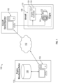
- FIG. 1 a functional block diagram of one embodiment of a system 100 that provides end-use specific customization of gas turbine engine operation is depicted.
- the system 100 includes a first processing unit 102, a second processing unit 104, a memory storage unit 106, and a gas turbine engine system 108.
- first processing unit 102 a second processing unit 104
- memory storage unit 106 a memory storage unit 106
- gas turbine engine system 108 a gas turbine engine system 108.
- FIG.1 the system 100 may be implemented with multiple first processing units 102, multiple second processing units 104, multiple memory storage units 106, and/or multiple gas turbine engine systems 108.
- the first processing unit 102 is owned, operated, and/or otherwise controlled by an owner/operator of the gas turbine engine system 108.
- the gas turbine engine system 108 is installed in an aircraft 110, and thus the owner/operator is an aircraft owner/operator.
- the first processing unit 102 is disposed remote from both the second processing unit 104 and memory storage unit 106, and may selectively communicate with the second processing unit 104 via an interconnected communication network 112, such as the Internet or any one of numerous other suitable communication mediums.
- the first processing unit 102 may be implemented using any one of numerous types of processing devices. For example, it may be a desktop terminal, a laptop device, a notebook device, a tablet device, or any one of numerous types of handheld device. Moreover, the first processing unit 102 may be in operable communication with the interconnected communication network 112 directly, or indirectly via a communication server or other device.
- the first processing unit 102 includes at least one processor and a computer-readable storage device or media encoded with programming instructions for configuring the controller.
- the processor may be any custom-made or commercially available processor, a central processing unit (CPU), a graphics processing unit (GPU), an application specific integrated circuit (ASIC), a field programmable gate array (FPGA), an auxiliary processor among several processors associated with the controller, a semiconductor-based microprocessor (in the form of a microchip or chip set), any combination thereof, or generally any device for executing instructions.
- the computer readable storage device or media may include volatile and nonvolatile storage in read-only memory (ROM), random-access memory (RAM), and keep-alive memory (KAM), for example.
- KAM is a persistent or non-volatile memory that may be used to store various operating variables while the processor is powered down.
- the computer-readable storage device or media may be implemented using any of a number of known memory devices such as PROMs (programmable read-only memory), EPROMs (electrically PROM), EEPROMs (electrically erasable PROM), flash memory, or any other electric, magnetic, optical, or combination memory devices capable of storing data, some of which represent executable programming instructions, used by the processor.
- the first processing unit 102 may be placed in operable communication with the gas turbine engine system 108. Although FIG. 1 depicts this communication occurring separate from the interconnected communication network 112, it will be appreciated that, at least in some embodiments, such communication could indeed be via the interconnected communication network 112. Moreover, the communication between the first processing unit 102 and the gas turbine engine system 108 could be via a wired connection, a wireless connection, or any combination thereof. The first processing unit 102 may thus be disposed remotely from the aircraft 110 or be collocated with the aircraft 110.
- the second processing unit 104 is owned, operated, and/or otherwise controlled by a manufacturer/seller of the gas turbine engine system 108. As noted above, the second processing unit 104 is disposed remote from the first processing unit 102 and memory, and may selectively communicate with the first processing unit 102 via the interconnected communication network 112. The second processing unit 104 may be disposed in one or more designated sites 114 established by the manufacturer/seller.
- the second processing unit 104 may also be implemented using any one of numerous types of processing devices. For example, it may be a desktop terminal, a laptop device, a notebook device, a tablet device, or any one of numerous types of handheld device. Moreover, the second processing unit 104 may be in operable communication with the interconnected communication network 112 directly, or indirectly via a communication server or other device.
- the second processing unit 104 also includes at least one processor and a computer-readable storage device or media encoded with programming instructions for configuring the controller.
- the processor may be any custom-made or commercially available processor, a central processing unit (CPU), a graphics processing unit (GPU), an application specific integrated circuit (ASIC), a field programmable gate array (FPGA), an auxiliary processor among several processors associated with the controller, a semiconductor-based microprocessor (in the form of a microchip or chip set), any combination thereof, or generally any device for executing instructions.
- the computer readable storage device or media may include volatile and nonvolatile storage in read-only memory (ROM), random-access memory (RAM), and keep-alive memory (KAM), for example.
- KAM is a persistent or non-volatile memory that may be used to store various operating variables while the processor is powered down.
- the computer-readable storage device or media may be implemented using any of a number of known memory devices such as PROMs (programmable read-only memory), EPROMs (electrically PROM), EEPROMs (electrically erasable PROM), flash memory, or any other electric, magnetic, optical, or combination memory devices capable of storing data, some of which represent executable programming instructions, used by the processor.
- the second processing unit 104 is also in operable communication with the memory storage unit 106.
- the memory storage unit 106 is depicted as being collocated with the second processing unit 104, it will be appreciated that it may also be disposed remote from the second processing unit 104.
- FIG. 1 depicts the communication occurring separate from the interconnected communication network 112, it will be appreciated that, at least in some embodiments, such communication could indeed be via the interconnected communication network 112.
- the communication between the second processing unit 104 and the memory storage unit 106 could be via a wired connection, a wireless connection, or any combination thereof.
- the memory storage unit 106 may be implemented using any one of numerous data storage devices. Some non-limiting examples include any of a number of known memory devices such as PROMs (programmable read-only memory), EPROMs (electrically PROM), EEPROMs (electrically erasable PROM), flash memory, or any other electric, magnetic, optical, or combination memory devices capable of storing data.
- PROMs programmable read-only memory
- EPROMs electrically PROM
- EEPROMs electrically erasable PROM
- flash memory or any other electric, magnetic, optical, or combination memory devices capable of storing data.
- the memory storage unit 106 stores at least a plurality of activation keys.
- the activation keys enable various operational parameters to allow the gas turbine engine system 108 to be operated in accordance with desired operational goals of the owner/operator.
- Each activation key is at least unique to each end-use environment, such as each aircraft 110 in an aircraft fleet, and to each type of gas turbine engine system 108.
- an activation key will be unique to the specific tail number of the aircraft 110 and to the specific type of gas turbine engine system 108 installed on the aircraft 110.
- the gas turbine engine system 108 includes both a gas turbine engine 116 and an associated engine controller 118.
- the first processing unit 102 is placed in operable communication with both the gas turbine engine 116 and the associated engine controller 118. This is because the activation key that is requested by the first processing unit 102 is stored in and verified by both the gas turbine engine 116 and its associated controller 118.
- the gas turbine engine 116 has a memory storage unit 122 disposed therein, and its associated controller 118 also has a memory storage unit 124 disposed therein.
- These memory storage units 122, 124 each store at least one or more known-to-be-valid activation keys.
- the activation key(s) need not be retransmitted and restored if either the gas turbine engine 116 or engine controller 118 are replaced.
- the one or more known-to-be-valid activation keys stored in the engine memory storage unit 122 will be automatically transferred to the controller memory storage unit 124.
- the gas turbine engine 116 is replaced, the one or more known-to-be-valid activation keys stored in the controller memory storage unit 124 will be automatically transferred to the engine memory storage unit 122.
- the engine controller 118 is configured to control the operation of the gas turbine engine 116, while maintaining the engine operating parameters within appropriate limits. To do so, the engine controller implements control logic that controls overall gas turbine engine operation over a range of specified operational parameters.
- the operational parameters which are stored in the engine controller 118, are unique to each type of gas turbine engine 116, and may be established during manufacture and initial testing of the gas turbine engine 116. Typically, these standard default operational parameters are fixed, and provide significant amounts operational margin. As a result, the gas turbine engine 116 may not operate in a manner that meets the owner/operator's goals.
- control logic implemented in the engine controller 118 allows the engine controller 118 to vary (either increasing or decreasing) one or more of the standard default operational parameters (to thereby raise or lower the operational margin) to implement multiple modes of operation.
- gas turbine engine operation may be optimized to provide specific levels of various energy output while maintaining the gas turbine parameters under the maximum safe limits of operation.
- These multiple operational modes allow combinations of energy output ranges tailored to specific end-user operational goals.
- These operational goals may vary, and may include one or more of maximum power, minimum fuel consumption, and maximum time between overhaul, just to name a few. It will additionally be appreciated that the operational parameters may vary. Some non-limiting examples include cool-down cycle time, rotational speed limits, pneumatic output, and energy output, just to name a few.
- the one or more activation keys retrieved by the first processing unit 102 and transmitted to the gas turbine engine system 108 will enable the operational parameters associated with the operational goals.
- the control logic within the engine controller 118 will verify the activation key that it receives by comparing the received activation key to the known-to-be-valid activation keys stored in the controller memory storage unit 124. Upon verification, the engine controller 118 will enable the operational parameters associated with the one or more activation keys. Because, as noted above, each activation key is also unique to each end-use environment, such as each aircraft 110 in an aircraft fleet, an owner/operator can individually configure each of its end-use systems, such as each aircraft in its fleet.
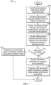
- FIG. 2 depicts one embodiment of the process in flowchart form. It should be noted that the parenthetical references in the following description refer to like-numbered flowchart blocks in FIG. 2 .
- the process 200 begins when an owner/operator (e.g., an aircraft owner/operator) determines its desired operational goals (202) and then, based on this determination, requests one or more appropriate activation keys from the engine manufacturer/seller (204). As noted above, this request is made from the first processing unit 102 to the second processing unit 104, via the interconnected communication network 112. In response, the engine manufacturer/seller retrieves the activation key(s) from the memory storage unit 106, and transmits the retrieved activation key(s) to the owner/operator (206). Again, this transmission is from the second processing unit 104 to the first processing unit 102, via the interconnected communication network 112.
- an owner/operator e.g., an aircraft owner/operator
- the owner/operator upon receipt of the activation key(s), transmits the activation key(s) to the gas turbine engine 116 and engine controller 118 on the specific aircraft (208).
- the engine controller 108 uses the installed control logic, compares the received activation key(s) to the known-to-be-valid activation keys stored in the memory storage unit 124 to verify whether the activation key(s) is (are) correct (210). If it is not, then the engine controller 118 controls the gas turbine engine 116 using the standard default operational parameters (212). If, however, the activation key(s) is (are) verified, the associated operational parameters in the gas turbine engine 116 and engine controller 118 are enabled (214), and the gas turbine engine 116 is operated and controlled using the enabled operational parameters (216).
- the system and method described herein provides end-use specific customization of gas turbine engine operation.
- the system and method allow existing end-users to customize the functionality of the gas turbine engine based on current needs.
- overall gas turbine engine system design may be optimized to meet end-user needs.
- a system for providing end-use specific customization of gas turbine engine operation includes a gas turbine engine, a first processing unit, and an engine controller.
- the first processing unit is configured to selectively transmit an activation key.
- the engine controller is in operable communication with the first processing unit and the gas turbine engine.
- the engine controller is configured to receive the activation key transmitted by the first processing unit and is operable, upon receipt of the activation key, to: verify the received activation key is correct, enable operational parameters in the gas turbine engine and the engine controller when the received activation key is correct, and control the gas turbine engine using the enabled operational parameters.
- the system of may include a controller memory storage unit disposed within the engine controller that has at least one activation key stored therein.
- the system may include an engine memory storage unit disposed within the gas turbine engine that has at least one activation key stored therein.
- the first processing unit may be further configured to transmit a request for the activation key and, upon receipt of the requested activation key, to transmit the requested activation key to the engine controller.
- the first processing unit may be further configured to transmit the requested activation key to the gas turbine engine.
- the system may include a second processing unit disposed remote from, and in operable communication with, the first processing unit.
- the second processing unit may be configured to receive the request from the first processing unit and be configured, upon receipt of the request, to transmit the requested activation key to the first processing unit.
- the system may include a memory storage unit in operable communication with the second processing unit.
- the memory storage unit may have a plurality of activation keys stored therein.
- the second processing unit may be further configured, upon receipt of the request from the first processing unit, to retrieve the requested activation key from the memory storage device.
- the first processing unit and the second processing unit may be in operable communication via an interconnected communication network.
- a system for providing end-use specific customization of gas turbine engine operation includes a first processing unit, a second processing unit, a gas turbine engine, and an engine controller.
- the first processing unit is configured to transmit a request for an activation key and, upon receipt of the requested activation key, to transmit the requested activation key.
- the second processing unit is disposed remote from, and is in operable communication with, the first processing unit.
- the second processing unit is configured to receive the request from the first processing unit and is configured, upon receipt of the request, to transmit the requested activation key to the first processing unit.
- the gas turbine engine is in operable communication with the first processing unit.
- the gas turbine engine is configured to receive the activation key transmitted by the first processing unit.
- the engine controller is in operable communication with the first processing unit and the gas turbine engine.
- the engine controller is configured to receive the activation key transmitted by the first processing unit and operable, upon receipt of the activation key, to: verify the received activation key is correct, enable operational parameters in the gas turbine engine and the engine controller when the received activation key is correct, and control the gas turbine engine using the enabled operational parameters.
- the system may include a memory storage unit in operable communication with the second processing unit that has a plurality of activation keys stored therein.
- the second processing unit may be further configured, upon receipt of the request from the first processing unit, to retrieve the requested activation key from the memory storage device.
- the system may include a controller memory storage unit disposed within the engine controller and having at least one activation key stored therein.
- the system may include an engine memory storage unit disposed within the gas turbine engine that has at least one activation key stored therein.
- the first processing unit and the second processing unit may be in operable communication via an interconnected communication network.
- a method for providing end-use specific customization of gas turbine engine operation includes requesting, from a first processing unit to a second processing unit, one or more activation keys; transmitting, from the second processing unit to the first processing unit, the one or more activation keys the were requested; transmitting the one or more activation keys from the first processing unit to a gas turbine engine and an engine controller; verifying, using control logic in the engine controller, whether the one or more activation keys are correct; enabling selected operational parameters in the gas turbine engine and engine controller when the one or more activation keys are verified; and operating and controlling the gas turbine engine using the enabled operational parameters.
- the second processing unit may be used to retrieve the one or more activation keys from a memory storage unit.
- Th gas turbine engine may be operated and controlled using standard default operational parameters when the one or more activation keys are not verified.
- the first processing unit and the second processing unit may be in operable communication via an interconnected communication network.
- Skilled artisans may implement the described functionality in varying ways for each particular application, but such implementation decisions should not be interpreted as causing a departure from the scope of the present invention.
- an embodiment of a system or a component may employ various integrated circuit components, e.g., memory elements, digital signal processing elements, logic elements, look-up tables, or the like, which may carry out a variety of functions under the control of one or more microprocessors or other control devices.
- integrated circuit components e.g., memory elements, digital signal processing elements, logic elements, look-up tables, or the like, which may carry out a variety of functions under the control of one or more microprocessors or other control devices.
- DSP digital signal processor
- ASIC application specific integrated circuit
- FPGA field programmable gate array
- a general-purpose processor may be a microprocessor, but in the alternative, the processor may be any conventional processor, controller, microcontroller, or state machine.
- a processor may also be implemented as a combination of computing devices, e.g., a combination of a DSP and a microprocessor, a plurality of microprocessors, one or more microprocessors in conjunction with a DSP core, or any other such configuration.
- a software module may reside in RAM memory, flash memory, ROM memory, EPROM memory, EEPROM memory, registers, hard disk, a removable disk, a CD-ROM, or any other form of storage medium known in the art.
- An exemplary storage medium is coupled to the processor such that the processor can read information from, and write information to, the storage medium.
- the storage medium may be integral to the processor.
- the processor and the storage medium may reside in an ASIC.
- an embodiment of a system or a component may employ various integrated circuit components, e.g., memory elements, digital signal processing elements, logic elements, look-up tables, or the like, which may carry out a variety of functions under the control of one or more microprocessors or other control devices.
- integrated circuit components e.g., memory elements, digital signal processing elements, logic elements, look-up tables, or the like, which may carry out a variety of functions under the control of one or more microprocessors or other control devices.
- various elements of the systems described herein are essentially the code segments or instructions that perform the various tasks.
- the program or code segments can be stored in a processor-readable medium or transmitted by a computer data signal embodied in a carrier wave over a transmission medium or communication path.
- the "computer-readable medium”, “processor-readable medium”, or “machine-readable medium” may include any medium that can store or transfer information. Examples of the processor-readable medium include an electronic circuit, a semiconductor memory device, a ROM, a flash memory, an erasable ROM (EROM), a floppy diskette, a CD-ROM, an optical disk, a hard disk, a fiber optic medium, a radio frequency (RF) link, or the like.
- RF radio frequency
- the computer data signal may include any signal that can propagate over a transmission medium such as electronic network channels, optical fibers, air, electromagnetic paths, or RF links.
- the code segments may be downloaded via computer networks such as the Internet, an intranet, a LAN, or the like.
- modules Some of the functional units described in this specification have been referred to as "modules" in order to more particularly emphasize their implementation independence.
- functionality referred to herein as a module may be implemented wholly, or partially, as a hardware circuit comprising custom VLSI circuits or gate arrays, off-the-shelf semiconductors such as logic chips, transistors, or other discrete components.
- a module may also be implemented in programmable hardware devices such as field programmable gate arrays, programmable array logic, programmable logic devices, or the like. Modules may also be implemented in software for execution by various types of processors.
- An identified module of executable code may, for instance, comprise one or more physical or logical modules of computer instructions that may, for instance, be organized as an object, procedure, or function.
- the executables of an identified module need not be physically located together, but may comprise disparate instructions stored in different locations that, when joined logically together, comprise the module and achieve the stated purpose for the module.
- a module of executable code may be a single instruction, or many instructions, and may even be distributed over several different code segments, among different programs, and across several memory devices.
- operational data may be embodied in any suitable form and organized within any suitable type of data structure. The operational data may be collected as a single data set, or may be distributed over different locations including over different storage devices, and may exist, at least partially, merely as electronic signals on a system or network.
Landscapes
- Engineering & Computer Science (AREA)
- General Engineering & Computer Science (AREA)
- Theoretical Computer Science (AREA)
- Software Systems (AREA)
- Chemical & Material Sciences (AREA)
- Mechanical Engineering (AREA)
- Computer Hardware Design (AREA)
- Computer Security & Cryptography (AREA)
- Physics & Mathematics (AREA)
- General Physics & Mathematics (AREA)
- Combustion & Propulsion (AREA)
- Multimedia (AREA)
- Technology Law (AREA)
- Computing Systems (AREA)
- Aviation & Aerospace Engineering (AREA)
- Computer Networks & Wireless Communication (AREA)
- Signal Processing (AREA)
- General Health & Medical Sciences (AREA)
- Bioethics (AREA)
- Health & Medical Sciences (AREA)
- Testing Of Engines (AREA)
- Testing And Monitoring For Control Systems (AREA)
Description
- The present invention generally relates to gas turbine engine operation, and more particularly relates to a system and method for providing end-use specific customization of gas turbine engine operation.
- Gas turbine engines are used in myriad environments and for various purposes. One environment where gas turbine engines is relatively ubiquitous is on an aircraft. The gas turbine engines on aircraft are used to generate and deliver various types of power. This power can be in the form of, but not limited to, pneumatic power, hydraulic power, rotational mechanical power, electric power, and propulsion thrust.
- The gas turbine engines on an aircraft (and in various other environments) are typically controlled via an engine controller. In general, the function of the engine controller is to govern the time, amount, and type of energy provided to the aircraft, while maintaining the gas turbine operating parameters within appropriate limits (e.g., maximum turbine temperature and maximum rotor speed).
- Most gas turbine engines are designed with significant amounts of operational margin, which means that the engines are, at times, operated at power levels beyond what is needed. As is generally known, the operational life of a gas turbine (time between overhaul) and the total fuel consumption are proportional to the percentage of time that the engine is operated at high levels of output. As such, many gas turbine engine end-users, such as aircraft owners/operators, would find it advantageous to be able to customize gas turbine engine operation to meet operational goals, while simultaneously extending gas turbine engine life.
- Unfortunately, existing gas turbine engine systems (i.e., the gas turbine engine and associated engine controller) do not provide the ability for end-users to selectively customize the functionality of the gas turbine engine based on current needs. Thus, overall gas turbine engine system design may not be optimal, especially for end-users with relatively large numbers of gas turbine engines, such as an owner/operator with a relatively large fleet of aircraft.
- Hence, there is a need for a system and method that provides aircraft-specific customization of gas turbine engine operation. The present invention addresses at least this need.
-
US2011/258633 discloses an information processing system that includes plural information processing apparatuses that have respective hardware resources including hardware resources to be licensed, each information processing apparatus performing information processing using the licensed hardware resources in which use rights are allocated; and a management apparatus that is connected to the plural information processing apparatuses and manages the hardware resources of the plural information processing apparatuses. The management apparatus includes a use right information holding unit that holds use right information corresponding to the use rights of the hardware resources, and a use right allocation unit that allocates the use rights to the hardware resources on a hardware resource basis in accordance with the held use right information. -
US2008/313472 discloses a method and apparatus for changing and adding activation keys for functions of digital content without having to change and recompile the digital content. The rules for validating activation keys, the code for providing instructions for executing the rules for validating the activation keys and a template for identifying possible activation keys, which keys are currently valid and validating rules associated with each currently valid activation key are separated and separately secured. -
US2007/136817 discloses wager gaming systems and methods for wager game license management in a network utilizing peer networking technology in the various embodiments. A network component, such as a server computer or a gaming machine, is deputized by a central licensing authority or other authorized license management component. The network component is deputized once it receives what may be referred to as a license deputizing certificate. Upon receiving this certificate or at some point thereafter, the deputized component is provided with various data relating to devices in the gaming network, wagering games available in the network, and network configuration data. The gaming network may have a primary network backbone and local peer gaming networks operating in conjunction with each other via the network backbone. A local peer gaming network may share wager game code, memory space, and other gaming-related resources. Once a network component is deputized to perform as an authorized license management component, it assumes the role of local licensing server for the gaming network or for a local peer gaming network. This component may be a gaming machine in a local peer network or an existing local license server which is now able to supply and manage the distribution of license tokens in a gaming network utilizing peer network technology. -
WO2010/057312 discloses an asset management system, which includes a hardware module operating as an asset control core. The asset control core generally includes a small hardware core embedded in a target system on chip that establishes a hardware-based point of trust on the silicon die. The asset control core can be used as a root of trust on a consumer device by having features that make it difficult to tamper with. The asset control core is able to generate a unique identifier for one device and participate in the tracking and provisioning of the device through a secure communication channel with an appliance. The appliance generally includes a secure module that caches and distributes provisioning data to one of many agents that connect to the asset control core, e.g. on a manufacturing line or in an after-market programming session. -
US2018/007547 discloses systems and methods for recording and communicating engine data, which is directed to a method for key management. The method includes generating a pair of keys, wherein one of the pair of keys is a private key, and wherein one of the pair of keys is a public key. The method includes transmitting the public key to a first remote computing device, wherein the first remote computing device transmits the public key to a second remote computing device. The method includes receiving a host key from the first remote computing device, wherein the first remote computing device received the host key from the second remote computing device. The method includes accessing the second remote computing device using the private key. The method includes verifying a request from the second remote computing device using the host key. -
US7036318 discloses a gas turbine electric powerplant, preferably driven by an aeroderivative turbine engine of split shaft design. The gas turbine engine is coupled to a speed reducer, which is in turn coupled to an electric generator. An engine mount is provided that ensures that the gas turbine engine will remain in proper alignment with the speed reducer and generator, even during the thermal expansion or contraction thereof. Preferably, the components comprising the powerplant are mounted to a common, transportable base, so that the powerplant can be delivered to various locations. An overspeed control system is provided for ensuring that a runaway condition of the gas turbine engine does not occur should the gas turbine engine become disconnected from the speed reducer or generator. Sensors are used to monitor multiple operating conditions of the powerplant. A microprocessor-based control system communicates with the sensors, and is further adapted to activate the overspeed control system if an overspeed condition is detected. - This summary is provided to describe select concepts in a simplified form that are further described in the Detailed Description. This summary is not intended to identify key or essential features of the claimed subject matter, nor is it intended to be used as an aid in determining the scope of the claimed subject matter.
- In one embodiment, a system for providing end-use specific customization of gas turbine engine operation includes a gas turbine engine, a first processing unit, and an engine controller. The first processing unit is configured to selectively transmit an activation key. The engine controller is in operable communication with the first processing unit and the gas turbine engine. The engine controller is configured to receive the activation key transmitted by the first processing unit and is operable, upon receipt of the activation key, to: verify the received activation key is correct, enable operational parameters in the gas turbine engine and the engine controller when the received activation key is correct, and control the gas turbine engine using the enabled operational parameters.
- In another embodiment, a system for providing end-use specific customization of gas turbine engine operation includes a first processing unit, a second processing unit, a gas turbine engine, and an engine controller. The first processing unit is configured to transmit a request for an activation key and, upon receipt of the requested activation key, to transmit the requested activation key. The second processing unit is disposed remote from, and is in operable communication with, the first processing unit. The second processing unit is configured to receive the request from the first processing unit and is configured, upon receipt of the request, to transmit the requested activation key to the first processing unit. The gas turbine engine is in operable communication with the first processing unit. The gas turbine engine is configured to receive the activation key transmitted by the first processing unit. The engine controller is in operable communication with the first processing unit and the gas turbine engine. The engine controller configured to receive the activation key transmitted by the first processing unit and operable, upon receipt of the activation key, to: verify the received activation key is correct, enable operational parameters in the gas turbine engine and the engine controller when the received activation key is correct, and control the gas turbine engine using the enabled operational parameters.
- In yet another embodiment, a method for providing end-use specific customization of gas turbine engine operation includes requesting, from a first processing unit to a second processing unit, one or more activation keys; transmitting, from the second processing unit to the first processing unit, the one or more activation keys the were requested; transmitting the one or more activation keys from the first processing unit to a gas turbine engine and an engine controller; verifying, using control logic in the engine controller, whether the one or more activation keys are correct; enabling selected operational parameters in the gas turbine engine and engine controller when the one or more activation keys are verified; and operating and controlling the gas turbine engine using the enabled operational parameters.
- Furthermore, other desirable features and characteristics of the disclosed system and method will become apparent from the subsequent detailed description, taken in conjunction with the accompanying drawings and the preceding background.
- The present invention will hereinafter be described in conjunction with the following drawing figures, wherein like numerals denote like elements, and wherein:
-
FIG. 1 depicts a functional block diagram of one embodiment of a system for providing aircraft-specific customization of gas turbine engine operation; and -
FIG. 2 depicts a process, in flowchart form, implemented in the system ofFIG. 1 for providing aircraft-specific customization of gas turbine engine operation. - The following detailed description is merely exemplary in nature and is not intended to limit the invention or the application and uses of the invention. As used herein, the word "exemplary" means "serving as an example, instance, or illustration." Thus, any embodiment described herein as "exemplary" is not necessarily to be construed as preferred or advantageous over other embodiments. All of the embodiments described herein are exemplary embodiments provided to enable persons skilled in the art to make or use the invention and not to limit the scope of the invention which is defined by the claims. Furthermore, there is no intention to be bound by any expressed or implied theory presented in the preceding technical field, background, brief summary, or the following detailed description. In this regard, although some specific embodiments may be depicted and described in the context of an end-user being an aircraft owner/operator, it will be appreciated in other embodiments the end-user context may vary.
- Referring to
FIG. 1 , a functional block diagram of one embodiment of asystem 100 that provides end-use specific customization of gas turbine engine operation is depicted. Thesystem 100 includes afirst processing unit 102, asecond processing unit 104, amemory storage unit 106, and a gasturbine engine system 108. Before proceeding further, it is noted that only one each of thefirst processing unit 102,second processing unit 104,memory storage unit 106, and gasturbine engine system 108 are depicted inFIG.1 . However, it should be further noted that this is done for clarity and ease of depiction. In other embodiments, thesystem 100 may be implemented with multiplefirst processing units 102, multiplesecond processing units 104, multiplememory storage units 106, and/or multiple gasturbine engine systems 108. - The
first processing unit 102 is owned, operated, and/or otherwise controlled by an owner/operator of the gasturbine engine system 108. In the depicted embodiment, the gasturbine engine system 108 is installed in anaircraft 110, and thus the owner/operator is an aircraft owner/operator. In the depicted embodiment, thefirst processing unit 102 is disposed remote from both thesecond processing unit 104 andmemory storage unit 106, and may selectively communicate with thesecond processing unit 104 via aninterconnected communication network 112, such as the Internet or any one of numerous other suitable communication mediums. - The
first processing unit 102 may be implemented using any one of numerous types of processing devices. For example, it may be a desktop terminal, a laptop device, a notebook device, a tablet device, or any one of numerous types of handheld device. Moreover, thefirst processing unit 102 may be in operable communication with theinterconnected communication network 112 directly, or indirectly via a communication server or other device. - No matter its specific implementation, the
first processing unit 102 includes at least one processor and a computer-readable storage device or media encoded with programming instructions for configuring the controller. The processor may be any custom-made or commercially available processor, a central processing unit (CPU), a graphics processing unit (GPU), an application specific integrated circuit (ASIC), a field programmable gate array (FPGA), an auxiliary processor among several processors associated with the controller, a semiconductor-based microprocessor (in the form of a microchip or chip set), any combination thereof, or generally any device for executing instructions. - The computer readable storage device or media may include volatile and nonvolatile storage in read-only memory (ROM), random-access memory (RAM), and keep-alive memory (KAM), for example. KAM is a persistent or non-volatile memory that may be used to store various operating variables while the processor is powered down. The computer-readable storage device or media may be implemented using any of a number of known memory devices such as PROMs (programmable read-only memory), EPROMs (electrically PROM), EEPROMs (electrically erasable PROM), flash memory, or any other electric, magnetic, optical, or combination memory devices capable of storing data, some of which represent executable programming instructions, used by the processor.
- As
FIG. 1 also depicts, thefirst processing unit 102 may be placed in operable communication with the gasturbine engine system 108. AlthoughFIG. 1 depicts this communication occurring separate from theinterconnected communication network 112, it will be appreciated that, at least in some embodiments, such communication could indeed be via theinterconnected communication network 112. Moreover, the communication between thefirst processing unit 102 and the gasturbine engine system 108 could be via a wired connection, a wireless connection, or any combination thereof. Thefirst processing unit 102 may thus be disposed remotely from theaircraft 110 or be collocated with theaircraft 110. - The
second processing unit 104 is owned, operated, and/or otherwise controlled by a manufacturer/seller of the gasturbine engine system 108. As noted above, thesecond processing unit 104 is disposed remote from thefirst processing unit 102 and memory, and may selectively communicate with thefirst processing unit 102 via theinterconnected communication network 112. Thesecond processing unit 104 may be disposed in one or more designatedsites 114 established by the manufacturer/seller. - Similar to the
first processing unit 102, thesecond processing unit 104 may also be implemented using any one of numerous types of processing devices. For example, it may be a desktop terminal, a laptop device, a notebook device, a tablet device, or any one of numerous types of handheld device. Moreover, thesecond processing unit 104 may be in operable communication with theinterconnected communication network 112 directly, or indirectly via a communication server or other device. - No matter its specific implementation, the
second processing unit 104 also includes at least one processor and a computer-readable storage device or media encoded with programming instructions for configuring the controller. The processor may be any custom-made or commercially available processor, a central processing unit (CPU), a graphics processing unit (GPU), an application specific integrated circuit (ASIC), a field programmable gate array (FPGA), an auxiliary processor among several processors associated with the controller, a semiconductor-based microprocessor (in the form of a microchip or chip set), any combination thereof, or generally any device for executing instructions. - The computer readable storage device or media may include volatile and nonvolatile storage in read-only memory (ROM), random-access memory (RAM), and keep-alive memory (KAM), for example. KAM is a persistent or non-volatile memory that may be used to store various operating variables while the processor is powered down. The computer-readable storage device or media may be implemented using any of a number of known memory devices such as PROMs (programmable read-only memory), EPROMs (electrically PROM), EEPROMs (electrically erasable PROM), flash memory, or any other electric, magnetic, optical, or combination memory devices capable of storing data, some of which represent executable programming instructions, used by the processor.
- The
second processing unit 104 is also in operable communication with thememory storage unit 106. Although, for sake of clarity and ease of illustration, thememory storage unit 106 is depicted as being collocated with thesecond processing unit 104, it will be appreciated that it may also be disposed remote from thesecond processing unit 104. In addition, althoughFIG. 1 depicts the communication occurring separate from theinterconnected communication network 112, it will be appreciated that, at least in some embodiments, such communication could indeed be via theinterconnected communication network 112. Moreover, the communication between thesecond processing unit 104 and thememory storage unit 106 could be via a wired connection, a wireless connection, or any combination thereof. - The
memory storage unit 106 may be implemented using any one of numerous data storage devices. Some non-limiting examples include any of a number of known memory devices such as PROMs (programmable read-only memory), EPROMs (electrically PROM), EEPROMs (electrically erasable PROM), flash memory, or any other electric, magnetic, optical, or combination memory devices capable of storing data. - No matter its specific implementation, however, the
memory storage unit 106 stores at least a plurality of activation keys. As will be described further below, the activation keys enable various operational parameters to allow the gasturbine engine system 108 to be operated in accordance with desired operational goals of the owner/operator. Each activation key is at least unique to each end-use environment, such as eachaircraft 110 in an aircraft fleet, and to each type of gasturbine engine system 108. Thus, in the context of an aircraft fleet, an activation key will be unique to the specific tail number of theaircraft 110 and to the specific type of gasturbine engine system 108 installed on theaircraft 110. - The gas
turbine engine system 108 includes both agas turbine engine 116 and an associatedengine controller 118. Thefirst processing unit 102 is placed in operable communication with both thegas turbine engine 116 and the associatedengine controller 118. This is because the activation key that is requested by thefirst processing unit 102 is stored in and verified by both thegas turbine engine 116 and its associatedcontroller 118. As such, and asFIG. 1 further depicts, thegas turbine engine 116 has amemory storage unit 122 disposed therein, and its associatedcontroller 118 also has amemory storage unit 124 disposed therein. Thesememory storage units gas turbine engine 116 orengine controller 118 are replaced. In particular, if theengine controller 118 is replaced, the one or more known-to-be-valid activation keys stored in the enginememory storage unit 122 will be automatically transferred to the controllermemory storage unit 124. Similarly, if thegas turbine engine 116 is replaced, the one or more known-to-be-valid activation keys stored in the controllermemory storage unit 124 will be automatically transferred to the enginememory storage unit 122. - The
engine controller 118, as is generally known, is configured to control the operation of thegas turbine engine 116, while maintaining the engine operating parameters within appropriate limits. To do so, the engine controller implements control logic that controls overall gas turbine engine operation over a range of specified operational parameters. The operational parameters, which are stored in theengine controller 118, are unique to each type ofgas turbine engine 116, and may be established during manufacture and initial testing of thegas turbine engine 116. Typically, these standard default operational parameters are fixed, and provide significant amounts operational margin. As a result, thegas turbine engine 116 may not operate in a manner that meets the owner/operator's goals. - In the depicted embodiment, the control logic implemented in the
engine controller 118 allows theengine controller 118 to vary (either increasing or decreasing) one or more of the standard default operational parameters (to thereby raise or lower the operational margin) to implement multiple modes of operation. As a result, gas turbine engine operation may be optimized to provide specific levels of various energy output while maintaining the gas turbine parameters under the maximum safe limits of operation. These multiple operational modes allow combinations of energy output ranges tailored to specific end-user operational goals. These operational goals may vary, and may include one or more of maximum power, minimum fuel consumption, and maximum time between overhaul, just to name a few. It will additionally be appreciated that the operational parameters may vary. Some non-limiting examples include cool-down cycle time, rotational speed limits, pneumatic output, and energy output, just to name a few. - The one or more activation keys retrieved by the
first processing unit 102 and transmitted to the gasturbine engine system 108 will enable the operational parameters associated with the operational goals. In particular, the control logic within theengine controller 118 will verify the activation key that it receives by comparing the received activation key to the known-to-be-valid activation keys stored in the controllermemory storage unit 124. Upon verification, theengine controller 118 will enable the operational parameters associated with the one or more activation keys. Because, as noted above, each activation key is also unique to each end-use environment, such as eachaircraft 110 in an aircraft fleet, an owner/operator can individually configure each of its end-use systems, such as each aircraft in its fleet. - Having described the
overall system 100 and its sub-systems and components, the process implemented in thesystem 100 for providing aircraft-specific customization of gas turbine engine operation will now be described. In so doing, reference should be made toFIG. 2 , which depicts one embodiment of the process in flowchart form. It should be noted that the parenthetical references in the following description refer to like-numbered flowchart blocks inFIG. 2 . - The
process 200 begins when an owner/operator (e.g., an aircraft owner/operator) determines its desired operational goals (202) and then, based on this determination, requests one or more appropriate activation keys from the engine manufacturer/seller (204). As noted above, this request is made from thefirst processing unit 102 to thesecond processing unit 104, via theinterconnected communication network 112. In response, the engine manufacturer/seller retrieves the activation key(s) from thememory storage unit 106, and transmits the retrieved activation key(s) to the owner/operator (206). Again, this transmission is from thesecond processing unit 104 to thefirst processing unit 102, via theinterconnected communication network 112. - The owner/operator, upon receipt of the activation key(s), transmits the activation key(s) to the
gas turbine engine 116 andengine controller 118 on the specific aircraft (208). Theengine controller 108, using the installed control logic, compares the received activation key(s) to the known-to-be-valid activation keys stored in thememory storage unit 124 to verify whether the activation key(s) is (are) correct (210). If it is not, then theengine controller 118 controls thegas turbine engine 116 using the standard default operational parameters (212). If, however, the activation key(s) is (are) verified, the associated operational parameters in thegas turbine engine 116 andengine controller 118 are enabled (214), and thegas turbine engine 116 is operated and controlled using the enabled operational parameters (216). - The system and method described herein provides end-use specific customization of gas turbine engine operation. In particular, the system and method allow existing end-users to customize the functionality of the gas turbine engine based on current needs. Thus, overall gas turbine engine system design may be optimized to meet end-user needs.
- In one embodiment, a system for providing end-use specific customization of gas turbine engine operation includes a gas turbine engine, a first processing unit, and an engine controller. The first processing unit is configured to selectively transmit an activation key. The engine controller is in operable communication with the first processing unit and the gas turbine engine. The engine controller is configured to receive the activation key transmitted by the first processing unit and is operable, upon receipt of the activation key, to: verify the received activation key is correct, enable operational parameters in the gas turbine engine and the engine controller when the received activation key is correct, and control the gas turbine engine using the enabled operational parameters.
- These aspects and other embodiments may include one or more of the following features. The system of may include a controller memory storage unit disposed within the engine controller that has at least one activation key stored therein. The system may include an engine memory storage unit disposed within the gas turbine engine that has at least one activation key stored therein. The first processing unit may be further configured to transmit a request for the activation key and, upon receipt of the requested activation key, to transmit the requested activation key to the engine controller. The first processing unit may be further configured to transmit the requested activation key to the gas turbine engine. The system may include a second processing unit disposed remote from, and in operable communication with, the first processing unit. The second processing unit may be configured to receive the request from the first processing unit and be configured, upon receipt of the request, to transmit the requested activation key to the first processing unit. The system may include a memory storage unit in operable communication with the second processing unit. The memory storage unit may have a plurality of activation keys stored therein. The second processing unit may be further configured, upon receipt of the request from the first processing unit, to retrieve the requested activation key from the memory storage device. The first processing unit and the second processing unit may be in operable communication via an interconnected communication network.
- In another embodiment, a system for providing end-use specific customization of gas turbine engine operation includes a first processing unit, a second processing unit, a gas turbine engine, and an engine controller. The first processing unit is configured to transmit a request for an activation key and, upon receipt of the requested activation key, to transmit the requested activation key. The second processing unit is disposed remote from, and is in operable communication with, the first processing unit. The second processing unit is configured to receive the request from the first processing unit and is configured, upon receipt of the request, to transmit the requested activation key to the first processing unit. The gas turbine engine is in operable communication with the first processing unit. The gas turbine engine is configured to receive the activation key transmitted by the first processing unit. The engine controller is in operable communication with the first processing unit and the gas turbine engine. The engine controller is configured to receive the activation key transmitted by the first processing unit and operable, upon receipt of the activation key, to: verify the received activation key is correct, enable operational parameters in the gas turbine engine and the engine controller when the received activation key is correct, and control the gas turbine engine using the enabled operational parameters.
- These aspects and other embodiments may include one or more of the following features. The system may include a memory storage unit in operable communication with the second processing unit that has a plurality of activation keys stored therein. The second processing unit may be further configured, upon receipt of the request from the first processing unit, to retrieve the requested activation key from the memory storage device. The system may include a controller memory storage unit disposed within the engine controller and having at least one activation key stored therein. The system may include an engine memory storage unit disposed within the gas turbine engine that has at least one activation key stored therein. The first processing unit and the second processing unit may be in operable communication via an interconnected communication network.
- In yet another embodiment, a method for providing end-use specific customization of gas turbine engine operation includes requesting, from a first processing unit to a second processing unit, one or more activation keys; transmitting, from the second processing unit to the first processing unit, the one or more activation keys the were requested; transmitting the one or more activation keys from the first processing unit to a gas turbine engine and an engine controller; verifying, using control logic in the engine controller, whether the one or more activation keys are correct; enabling selected operational parameters in the gas turbine engine and engine controller when the one or more activation keys are verified; and operating and controlling the gas turbine engine using the enabled operational parameters. These aspects and other embodiments may include one or more of the following features. The second processing unit may be used to retrieve the one or more activation keys from a memory storage unit. Th gas turbine engine may be operated and controlled using standard default operational parameters when the one or more activation keys are not verified. The first processing unit and the second processing unit may be in operable communication via an interconnected communication network.
- Those of skill in the art will appreciate that the various illustrative logical blocks, modules, circuits, and algorithm steps described in connection with the embodiments disclosed herein may be implemented as electronic hardware, computer software, or combinations of both. Some of the embodiments and implementations are described above in terms of functional and/or logical block components (or modules) and various processing steps. However, it should be appreciated that such block components (or modules) may be realized by any number of hardware, software, and/or firmware components configured to perform the specified functions. To clearly illustrate this interchangeability of hardware and software, various illustrative components, blocks, modules, circuits, and steps have been described above generally in terms of their functionality. Whether such functionality is implemented as hardware or software depends upon the particular application and design constraints imposed on the overall system. Skilled artisans may implement the described functionality in varying ways for each particular application, but such implementation decisions should not be interpreted as causing a departure from the scope of the present invention. For example, an embodiment of a system or a component may employ various integrated circuit components, e.g., memory elements, digital signal processing elements, logic elements, look-up tables, or the like, which may carry out a variety of functions under the control of one or more microprocessors or other control devices. In addition, those skilled in the art will appreciate that embodiments described herein are merely exemplary implementations.
- The various illustrative logical blocks, modules, and circuits described in connection with the embodiments disclosed herein may be implemented or performed with a general-purpose processor, a digital signal processor (DSP), an application specific integrated circuit (ASIC), a field programmable gate array (FPGA) or other programmable logic device, discrete gate or transistor logic, discrete hardware components, or any combination thereof designed to perform the functions described herein. A general-purpose processor may be a microprocessor, but in the alternative, the processor may be any conventional processor, controller, microcontroller, or state machine. A processor may also be implemented as a combination of computing devices, e.g., a combination of a DSP and a microprocessor, a plurality of microprocessors, one or more microprocessors in conjunction with a DSP core, or any other such configuration.
- The steps of a method or algorithm described in connection with the embodiments disclosed herein may be embodied directly in hardware, in a software module executed by a processor, or in a combination of the two. A software module may reside in RAM memory, flash memory, ROM memory, EPROM memory, EEPROM memory, registers, hard disk, a removable disk, a CD-ROM, or any other form of storage medium known in the art. An exemplary storage medium is coupled to the processor such that the processor can read information from, and write information to, the storage medium. In the alternative, the storage medium may be integral to the processor. The processor and the storage medium may reside in an ASIC.
- Techniques and technologies may be described herein in terms of functional and/or logical block components, and with reference to symbolic representations of operations, processing tasks, and functions that may be performed by various computing components or devices. Such operations, tasks, and functions are sometimes referred to as being computer-executed, computerized, software-implemented, or computer-implemented. In practice, one or more processor devices can carry out the described operations, tasks, and functions by manipulating electrical signals representing data bits at memory locations in the system memory, as well as other processing of signals. The memory locations where data bits are maintained are physical locations that have particular electrical, magnetic, optical, or organic properties corresponding to the data bits. It should be appreciated that the various block components shown in the figures may be realized by any number of hardware, software, and/or firmware components configured to perform the specified functions. For example, an embodiment of a system or a component may employ various integrated circuit components, e.g., memory elements, digital signal processing elements, logic elements, look-up tables, or the like, which may carry out a variety of functions under the control of one or more microprocessors or other control devices.
- When implemented in software or firmware, various elements of the systems described herein are essentially the code segments or instructions that perform the various tasks. The program or code segments can be stored in a processor-readable medium or transmitted by a computer data signal embodied in a carrier wave over a transmission medium or communication path. The "computer-readable medium", "processor-readable medium", or "machine-readable medium" may include any medium that can store or transfer information. Examples of the processor-readable medium include an electronic circuit, a semiconductor memory device, a ROM, a flash memory, an erasable ROM (EROM), a floppy diskette, a CD-ROM, an optical disk, a hard disk, a fiber optic medium, a radio frequency (RF) link, or the like. The computer data signal may include any signal that can propagate over a transmission medium such as electronic network channels, optical fibers, air, electromagnetic paths, or RF links. The code segments may be downloaded via computer networks such as the Internet, an intranet, a LAN, or the like.
- Some of the functional units described in this specification have been referred to as "modules" in order to more particularly emphasize their implementation independence. For example, functionality referred to herein as a module may be implemented wholly, or partially, as a hardware circuit comprising custom VLSI circuits or gate arrays, off-the-shelf semiconductors such as logic chips, transistors, or other discrete components. A module may also be implemented in programmable hardware devices such as field programmable gate arrays, programmable array logic, programmable logic devices, or the like. Modules may also be implemented in software for execution by various types of processors. An identified module of executable code may, for instance, comprise one or more physical or logical modules of computer instructions that may, for instance, be organized as an object, procedure, or function. Nevertheless, the executables of an identified module need not be physically located together, but may comprise disparate instructions stored in different locations that, when joined logically together, comprise the module and achieve the stated purpose for the module. Indeed, a module of executable code may be a single instruction, or many instructions, and may even be distributed over several different code segments, among different programs, and across several memory devices. Similarly, operational data may be embodied in any suitable form and organized within any suitable type of data structure. The operational data may be collected as a single data set, or may be distributed over different locations including over different storage devices, and may exist, at least partially, merely as electronic signals on a system or network.
- In this document, relational terms such as first and second, and the like may be used solely to distinguish one entity or action from another entity or action without necessarily requiring or implying any actual such relationship or order between such entities or actions. Numerical ordinals such as "first," "second," "third," etc. simply denote different singles of a plurality and do not imply any order or sequence unless specifically defined by the claim language. The sequence of the text in any of the claims does not imply that process steps must be performed in a temporal or logical order according to such sequence unless it is specifically defined by the language of the claim. The process steps may be interchanged in any order without departing from the scope of the invention as long as such an interchange does not contradict the claim language and is not logically nonsensical.
- Furthermore, depending on the context, words such as "connect" or "coupled to" used in describing a relationship between different elements do not imply that a direct physical connection must be made between these elements. For example, two elements may be connected to each other physically, electronically, logically, or in any other manner, through one or more additional elements.
- While at least one exemplary embodiment has been presented in the foregoing detailed description of the invention, it should be appreciated that a vast number of variations exist. It should also be appreciated that the exemplary embodiment or exemplary embodiments are only examples, and are not intended to limit the scope, applicability, or configuration of the invention in any way. Rather, the foregoing detailed description will provide those skilled in the art with a convenient road map for implementing an exemplary embodiment of the invention. It being understood that various changes may be made in the function and arrangement of elements described in an exemplary embodiment without departing from the scope of the invention as set forth herein.
Claims (11)
- A system (100) for providing end-use specific customization of gas turbine engine operation, the system (100) comprising:a gas turbine engine (116);a first processing unit (102) configured to transmit an activation key, the activation key having one or more operational parameters associated therewith; andan engine controller (118) in operable communication with the first processing unit (102) and the gas turbine engine (116), the engine controller (118) configured to receive the activation key transmitted by the first processing unit (102) and operable, upon receipt of the activation key, to:verify the received activation key is correct by comparing the received activation key to one or more known-to-be-valid activation keys,enable the one or more operational parameters associated with the activation key in the gas turbine engine (116) and the engine controller (118) when the received activation key is correct,control the gas turbine engine (116) using the enabled operational parameters; andwherein the system further comprises:a controller memory storage unit (124) disposed within the engine controller (118), the controller memory storage unit (124) having at least one known-to-be-valid activation key stored therein; andan engine memory storage unit (122) disposed within the gas turbine engine (116), the engine memory storage unit (122) having at least one known-to-be-valid activation key stored therein.
- The system of claim 1, wherein the first processing unit (102) is further configured to transmit a request for the activation key and, upon receipt of the requested activation key, to transmit the requested activation key to the engine controller (118).
- The system of claim 2, wherein the first processing unit (102) is further configured to transmit the requested activation key to the gas turbine engine (116).
- The system of claim 2, further comprising:
a second processing unit (104) disposed remote from, and in operable communication with, the first processing unit (102), the second processing unit (104) configured to receive the request from the first processing unit (102) and configured, upon receipt of the request, to transmit the requested activation key to the first processing unit (102). - The system of claim 4, further comprising:
a memory storage unit (106) in operable communication with the second processing unit (104), the memory storage unit (106) having a plurality of activation keys stored therein. - The system of claim 5, wherein the second processing unit (104) is further configured, upon receipt of the request from the first processing unit (102), to retrieve the requested activation key from the memory storage device (106).
- The system of claim 4, wherein the first processing unit (102) and the second processing unit (104) are in operable communication via an interconnected communication network (112).
- A method for providing end-use specific customization of gas turbine engine operation, the method comprising the steps of:requesting, from a first processing unit (102) to a second processing unit (104), one or more activation keys;transmitting, from the second processing unit (104) to the first processing unit (102), the one or more activation keys that were requested;transmitting the one or more activation keys from the first processing unit (102) to a gas turbine engine (116) and an engine controller (118);verifying, using control logic in the engine controller (118), whether the one or more activation keys are correct by comparing the one or more activation keys to one or more known-to-be-valid activation keys, stored in a controller memory storage unit (124) of the engine controller (118), and an engine memory storage unit (122) of the gas turbine engine (116);enabling operational parameters associated with the one or more activation keys in the gas turbine engine (116) and engine controller (118) when the one or more activation keys are verified; andoperating and controlling the gas turbine engine (116) using the enabled operational parameters.
- The method of claim 8, further comprising:
retrieving, using the second processing unit (104), the one or more activation keys from a memory storage unit (106). - The method of claim 8, further comprising:
operating and controlling the gas turbine engine (116) using standard default operational parameters when the one or more activation keys are not verified. - The method of claim 8, wherein the first processing unit (102) and the second processing unit (104) are in operable communication via an interconnected communication network (112).
Applications Claiming Priority (2)
| Application Number | Priority Date | Filing Date | Title |
|---|---|---|---|
| US201862690406P | 2018-06-27 | 2018-06-27 | |
| US16/357,020 US10946973B2 (en) | 2018-06-27 | 2019-03-18 | System and method for providing end-use specific customization of gas turbine engine operation |
Publications (2)
| Publication Number | Publication Date |
|---|---|
| EP3588336A1 EP3588336A1 (en) | 2020-01-01 |
| EP3588336B1 true EP3588336B1 (en) | 2023-08-02 |
Family
ID=67105701
Family Applications (1)
| Application Number | Title | Priority Date | Filing Date |
|---|---|---|---|
| EP19181324.5A Active EP3588336B1 (en) | 2018-06-27 | 2019-06-19 | System and method for providing end-use specific customization of gas turbine engine operation |
Country Status (2)
| Country | Link |
|---|---|
| US (1) | US10946973B2 (en) |
| EP (1) | EP3588336B1 (en) |
Families Citing this family (1)
| Publication number | Priority date | Publication date | Assignee | Title |
|---|---|---|---|---|
| US11391218B2 (en) * | 2019-03-22 | 2022-07-19 | Pratt & Whitney Canada Corp. | Method and system for setting power of an aircraft engine |
Citations (1)
| Publication number | Priority date | Publication date | Assignee | Title |
|---|---|---|---|---|
| US7036318B1 (en) * | 2002-04-16 | 2006-05-02 | Altek Power Corporation | Gas turbine electric powerplant |
Family Cites Families (23)
| Publication number | Priority date | Publication date | Assignee | Title |
|---|---|---|---|---|
| US6487096B1 (en) | 1997-09-08 | 2002-11-26 | Capstone Turbine Corporation | Power controller |
| US20070136817A1 (en) | 2000-12-07 | 2007-06-14 | Igt | Wager game license management in a peer gaming network |
| FR2871520B1 (en) | 2004-06-15 | 2008-12-26 | Eurocopter France | STEERING INDICATOR FOR PREDICTING THE EVOLUTION OF THE MONITORING PARAMETERS OF A TURBOMOTEUR |
| US7814334B2 (en) | 2007-06-18 | 2010-10-12 | International Business Machines Corporation | Method and apparatus for changing and adding activation keys for functions of digital content without having to change and recompile the digital content |
| JP5206795B2 (en) | 2008-10-21 | 2013-06-12 | 富士通株式会社 | Information processing system and unified usage right management method |
| SG171730A1 (en) | 2008-11-24 | 2011-07-28 | Certicom Corp | System and method for hardware based security |
| US8099227B2 (en) | 2009-03-19 | 2012-01-17 | Pratt & Whitney Canada Corp. | Control of gas turbine engine |
| US8417433B2 (en) | 2010-04-30 | 2013-04-09 | Alstom Technology Ltd. | Dynamically auto-tuning a gas turbine engine |
| US9342060B2 (en) | 2010-09-14 | 2016-05-17 | United Technologies Corporation | Adaptive control for a gas turbine engine |
| US9237146B1 (en) * | 2012-01-26 | 2016-01-12 | United Services Automobile Association | Quick-logon for computing device |
| WO2013123385A1 (en) | 2012-02-15 | 2013-08-22 | Rolls-Royce Corporation | Gas turbine engine performance seeking control |
| EP2904251B1 (en) | 2012-10-01 | 2019-06-26 | United Technologies Corporation | Method of defining gas turbine engine control ratings |
| US9014945B2 (en) | 2013-03-08 | 2015-04-21 | General Electric Company | Online enhancement for improved gas turbine performance |
| US9869305B1 (en) | 2013-03-14 | 2018-01-16 | Tucson Embedded Systems, Inc. | Pump-engine controller |
| EP2971699B8 (en) | 2013-03-15 | 2020-01-15 | Rolls-Royce Corporation | Lifing and performance optimization limit management for turbine engine |
| US9096325B2 (en) | 2013-11-18 | 2015-08-04 | Bell Helicopter Textron Inc. | Fly-by-wire engine power control system |
| US9605559B2 (en) | 2015-02-02 | 2017-03-28 | General Electric Company | Wash timing based on turbine operating parameters |
| US10040565B2 (en) | 2015-09-22 | 2018-08-07 | Honeywell International Inc. | Single lever turboprop control systems and methods utilizing torque-based and power based scheduling |
| EP3356231B1 (en) | 2015-09-30 | 2020-08-12 | Bombardier Inc. | Method of and system for presenting an operating status of an aircraft engine |
| US10904755B2 (en) * | 2016-06-14 | 2021-01-26 | SZ DJI Technology Co., Ltd. | Data distribution from a movable object |
| US10764747B2 (en) | 2016-06-30 | 2020-09-01 | Ge Aviation Systems Llc | Key management for wireless communication system for communicating engine data |
| US10496086B2 (en) | 2016-12-12 | 2019-12-03 | General Electric Company | Gas turbine engine fleet performance deterioration |
| US10604278B2 (en) | 2017-04-18 | 2020-03-31 | General Electric Company | Methods and apparatus to monitor health information of a turbine engine |
-
2019
- 2019-03-18 US US16/357,020 patent/US10946973B2/en active Active
- 2019-06-19 EP EP19181324.5A patent/EP3588336B1/en active Active
Patent Citations (1)
| Publication number | Priority date | Publication date | Assignee | Title |
|---|---|---|---|---|
| US7036318B1 (en) * | 2002-04-16 | 2006-05-02 | Altek Power Corporation | Gas turbine electric powerplant |
Also Published As
| Publication number | Publication date |
|---|---|
| EP3588336A1 (en) | 2020-01-01 |
| US20200002019A1 (en) | 2020-01-02 |
| US10946973B2 (en) | 2021-03-16 |
Similar Documents
| Publication | Publication Date | Title |
|---|---|---|
| CN105045608B (en) | System and method for managing the software upgrading in vehicle computing system | |
| JP6498914B2 (en) | Aircraft configuration and software component management using component software components | |
| JP7121482B2 (en) | Approval of aircraft data exchange using detectable differences between on-board electronics | |
| WO2017181204A1 (en) | System for verification of integrity of unmanned aerial vehicles | |
| US20180248702A1 (en) | System and method for managing installation of an application package requiring high-risk permission access | |
| US8484752B2 (en) | Verifying authenticity of electronic control unit code | |
| CN110222485B (en) | Industrial control white list management system and method based on SGX software protection extended instruction | |
| EP2801926B1 (en) | Use of multiple digital signatures and quorum rules to verify aircraft information | |
| CN103679005A (en) | Method to enable development mode of a secure electronic control unit | |
| CN110390184B (en) | Method, apparatus and computer program product for executing applications in the cloud | |
| CN105404268A (en) | Vehicle auditing and control of maintenance and diagnosis for vehicle systems | |
| WO2019127486A1 (en) | Method and apparatus for controlling unmanned aerial vehicle | |
| CN104036194B (en) | Vulnerability detection method and device for revealing private data in application program | |
| US20220294642A1 (en) | Use Right Information Processing Device, Use Right Information Processing System, and Use Right Information Processing Method, Based on Smart Contract | |
| EP3588336B1 (en) | System and method for providing end-use specific customization of gas turbine engine operation | |
| WO2017016609A1 (en) | Cryptographic data | |
| Li et al. | Over-the-air upgrading for enhancing security of intelligent connected vehicles: a survey | |
| EP3688948B1 (en) | PROVISION OF PROVIDER ACCESS DATA | |
| CN114157470A (en) | Token management method and device | |
| JP2022160125A (en) | Center, distribution control method, and distribution control program | |
| CN109314862A (en) | Data distribution from movable objects | |
| CN116910819A (en) | Remote confirmation of methods and systems for checking the integrity of computer programs in computing units | |
| CN118643484B (en) | A method for activating vehicle computer debugging authority | |
| JP2022158323A (en) | Center, distribution control method, and distribution control program | |
| JP6946213B2 (en) | Wireless system and wireless communication method |
Legal Events
| Date | Code | Title | Description |
|---|---|---|---|
| PUAI | Public reference made under article 153(3) epc to a published international application that has entered the european phase |
Free format text: ORIGINAL CODE: 0009012 |
|
| STAA | Information on the status of an ep patent application or granted ep patent |
Free format text: STATUS: THE APPLICATION HAS BEEN PUBLISHED |
|
| AK | Designated contracting states |
Kind code of ref document: A1 Designated state(s): AL AT BE BG CH CY CZ DE DK EE ES FI FR GB GR HR HU IE IS IT LI LT LU LV MC MK MT NL NO PL PT RO RS SE SI SK SM TR |
|
| AX | Request for extension of the european patent |
Extension state: BA ME |
|
| STAA | Information on the status of an ep patent application or granted ep patent |
Free format text: STATUS: REQUEST FOR EXAMINATION WAS MADE |
|
| 17P | Request for examination filed |
Effective date: 20200116 |
|
| RBV | Designated contracting states (corrected) |
Designated state(s): AL AT BE BG CH CY CZ DE DK EE ES FI FR GB GR HR HU IE IS IT LI LT LU LV MC MK MT NL NO PL PT RO RS SE SI SK SM TR |
|
| STAA | Information on the status of an ep patent application or granted ep patent |
Free format text: STATUS: EXAMINATION IS IN PROGRESS |
|
| 17Q | First examination report despatched |
Effective date: 20211025 |
|
| REG | Reference to a national code |
Free format text: PREVIOUS MAIN CLASS: G06F0021100000 Ref country code: DE Ref legal event code: R079 Ref document number: 602019033889 Country of ref document: DE Free format text: PREVIOUS MAIN CLASS: G06F0021100000 Ipc: B64D0031120000 |
|
| GRAP | Despatch of communication of intention to grant a patent |
Free format text: ORIGINAL CODE: EPIDOSNIGR1 |
|
| STAA | Information on the status of an ep patent application or granted ep patent |
Free format text: STATUS: GRANT OF PATENT IS INTENDED |
|
| RIC1 | Information provided on ipc code assigned before grant |
Ipc: G06F 21/62 20130101ALI20230126BHEP Ipc: G06F 21/10 20130101ALI20230126BHEP Ipc: B64D 31/12 20060101AFI20230126BHEP |
|
| INTG | Intention to grant announced |
Effective date: 20230215 |
|
| GRAS | Grant fee paid |
Free format text: ORIGINAL CODE: EPIDOSNIGR3 |
|
| P01 | Opt-out of the competence of the unified patent court (upc) registered |
Effective date: 20230421 |
|
| GRAA | (expected) grant |
Free format text: ORIGINAL CODE: 0009210 |
|
| STAA | Information on the status of an ep patent application or granted ep patent |
Free format text: STATUS: THE PATENT HAS BEEN GRANTED |
|
| AK | Designated contracting states |
Kind code of ref document: B1 Designated state(s): AL AT BE BG CH CY CZ DE DK EE ES FI FR GB GR HR HU IE IS IT LI LT LU LV MC MK MT NL NO PL PT RO RS SE SI SK SM TR |
|
| REG | Reference to a national code |
Ref country code: GB Ref legal event code: FG4D |
|
| REG | Reference to a national code |
Ref country code: CH Ref legal event code: EP |
|
| REG | Reference to a national code |
Ref country code: DE Ref legal event code: R096 Ref document number: 602019033889 Country of ref document: DE |
|
| REG | Reference to a national code |
Ref country code: IE Ref legal event code: FG4D |
|
| REG | Reference to a national code |
Ref country code: LT Ref legal event code: MG9D |
|
| REG | Reference to a national code |
Ref country code: NL Ref legal event code: MP Effective date: 20230802 |
|
| REG | Reference to a national code |
Ref country code: AT Ref legal event code: MK05 Ref document number: 1594477 Country of ref document: AT Kind code of ref document: T Effective date: 20230802 |
|
| PG25 | Lapsed in a contracting state [announced via postgrant information from national office to epo] |
Ref country code: GR Free format text: LAPSE BECAUSE OF FAILURE TO SUBMIT A TRANSLATION OF THE DESCRIPTION OR TO PAY THE FEE WITHIN THE PRESCRIBED TIME-LIMIT Effective date: 20231103 |
|
| PG25 | Lapsed in a contracting state [announced via postgrant information from national office to epo] |
Ref country code: IS Free format text: LAPSE BECAUSE OF FAILURE TO SUBMIT A TRANSLATION OF THE DESCRIPTION OR TO PAY THE FEE WITHIN THE PRESCRIBED TIME-LIMIT Effective date: 20231202 |
|
| PG25 | Lapsed in a contracting state [announced via postgrant information from national office to epo] |
Ref country code: SE Free format text: LAPSE BECAUSE OF FAILURE TO SUBMIT A TRANSLATION OF THE DESCRIPTION OR TO PAY THE FEE WITHIN THE PRESCRIBED TIME-LIMIT Effective date: 20230802 Ref country code: RS Free format text: LAPSE BECAUSE OF FAILURE TO SUBMIT A TRANSLATION OF THE DESCRIPTION OR TO PAY THE FEE WITHIN THE PRESCRIBED TIME-LIMIT Effective date: 20230802 Ref country code: PT Free format text: LAPSE BECAUSE OF FAILURE TO SUBMIT A TRANSLATION OF THE DESCRIPTION OR TO PAY THE FEE WITHIN THE PRESCRIBED TIME-LIMIT Effective date: 20231204 Ref country code: NO Free format text: LAPSE BECAUSE OF FAILURE TO SUBMIT A TRANSLATION OF THE DESCRIPTION OR TO PAY THE FEE WITHIN THE PRESCRIBED TIME-LIMIT Effective date: 20231102 Ref country code: NL Free format text: LAPSE BECAUSE OF FAILURE TO SUBMIT A TRANSLATION OF THE DESCRIPTION OR TO PAY THE FEE WITHIN THE PRESCRIBED TIME-LIMIT Effective date: 20230802 Ref country code: LV Free format text: LAPSE BECAUSE OF FAILURE TO SUBMIT A TRANSLATION OF THE DESCRIPTION OR TO PAY THE FEE WITHIN THE PRESCRIBED TIME-LIMIT Effective date: 20230802 Ref country code: LT Free format text: LAPSE BECAUSE OF FAILURE TO SUBMIT A TRANSLATION OF THE DESCRIPTION OR TO PAY THE FEE WITHIN THE PRESCRIBED TIME-LIMIT Effective date: 20230802 Ref country code: IS Free format text: LAPSE BECAUSE OF FAILURE TO SUBMIT A TRANSLATION OF THE DESCRIPTION OR TO PAY THE FEE WITHIN THE PRESCRIBED TIME-LIMIT Effective date: 20231202 Ref country code: HR Free format text: LAPSE BECAUSE OF FAILURE TO SUBMIT A TRANSLATION OF THE DESCRIPTION OR TO PAY THE FEE WITHIN THE PRESCRIBED TIME-LIMIT Effective date: 20230802 Ref country code: GR Free format text: LAPSE BECAUSE OF FAILURE TO SUBMIT A TRANSLATION OF THE DESCRIPTION OR TO PAY THE FEE WITHIN THE PRESCRIBED TIME-LIMIT Effective date: 20231103 Ref country code: FI Free format text: LAPSE BECAUSE OF FAILURE TO SUBMIT A TRANSLATION OF THE DESCRIPTION OR TO PAY THE FEE WITHIN THE PRESCRIBED TIME-LIMIT Effective date: 20230802 Ref country code: AT Free format text: LAPSE BECAUSE OF FAILURE TO SUBMIT A TRANSLATION OF THE DESCRIPTION OR TO PAY THE FEE WITHIN THE PRESCRIBED TIME-LIMIT Effective date: 20230802 |
|
| PG25 | Lapsed in a contracting state [announced via postgrant information from national office to epo] |
Ref country code: PL Free format text: LAPSE BECAUSE OF FAILURE TO SUBMIT A TRANSLATION OF THE DESCRIPTION OR TO PAY THE FEE WITHIN THE PRESCRIBED TIME-LIMIT Effective date: 20230802 |
|
| PG25 | Lapsed in a contracting state [announced via postgrant information from national office to epo] |
Ref country code: ES Free format text: LAPSE BECAUSE OF FAILURE TO SUBMIT A TRANSLATION OF THE DESCRIPTION OR TO PAY THE FEE WITHIN THE PRESCRIBED TIME-LIMIT Effective date: 20230802 |
|
| PG25 | Lapsed in a contracting state [announced via postgrant information from national office to epo] |
Ref country code: SM Free format text: LAPSE BECAUSE OF FAILURE TO SUBMIT A TRANSLATION OF THE DESCRIPTION OR TO PAY THE FEE WITHIN THE PRESCRIBED TIME-LIMIT Effective date: 20230802 Ref country code: RO Free format text: LAPSE BECAUSE OF FAILURE TO SUBMIT A TRANSLATION OF THE DESCRIPTION OR TO PAY THE FEE WITHIN THE PRESCRIBED TIME-LIMIT Effective date: 20230802 Ref country code: ES Free format text: LAPSE BECAUSE OF FAILURE TO SUBMIT A TRANSLATION OF THE DESCRIPTION OR TO PAY THE FEE WITHIN THE PRESCRIBED TIME-LIMIT Effective date: 20230802 Ref country code: EE Free format text: LAPSE BECAUSE OF FAILURE TO SUBMIT A TRANSLATION OF THE DESCRIPTION OR TO PAY THE FEE WITHIN THE PRESCRIBED TIME-LIMIT Effective date: 20230802 Ref country code: DK Free format text: LAPSE BECAUSE OF FAILURE TO SUBMIT A TRANSLATION OF THE DESCRIPTION OR TO PAY THE FEE WITHIN THE PRESCRIBED TIME-LIMIT Effective date: 20230802 Ref country code: CZ Free format text: LAPSE BECAUSE OF FAILURE TO SUBMIT A TRANSLATION OF THE DESCRIPTION OR TO PAY THE FEE WITHIN THE PRESCRIBED TIME-LIMIT Effective date: 20230802 Ref country code: SK Free format text: LAPSE BECAUSE OF FAILURE TO SUBMIT A TRANSLATION OF THE DESCRIPTION OR TO PAY THE FEE WITHIN THE PRESCRIBED TIME-LIMIT Effective date: 20230802 |
|
| REG | Reference to a national code |
Ref country code: DE Ref legal event code: R097 Ref document number: 602019033889 Country of ref document: DE |
|
| PG25 | Lapsed in a contracting state [announced via postgrant information from national office to epo] |
Ref country code: IT Free format text: LAPSE BECAUSE OF FAILURE TO SUBMIT A TRANSLATION OF THE DESCRIPTION OR TO PAY THE FEE WITHIN THE PRESCRIBED TIME-LIMIT Effective date: 20230802 |
|
| PLBE | No opposition filed within time limit |
Free format text: ORIGINAL CODE: 0009261 |
|
| STAA | Information on the status of an ep patent application or granted ep patent |
Free format text: STATUS: NO OPPOSITION FILED WITHIN TIME LIMIT |
|
| 26N | No opposition filed |
Effective date: 20240503 |
|
| PG25 | Lapsed in a contracting state [announced via postgrant information from national office to epo] |
Ref country code: SI Free format text: LAPSE BECAUSE OF FAILURE TO SUBMIT A TRANSLATION OF THE DESCRIPTION OR TO PAY THE FEE WITHIN THE PRESCRIBED TIME-LIMIT Effective date: 20230802 |
|
| PG25 | Lapsed in a contracting state [announced via postgrant information from national office to epo] |
Ref country code: BG Free format text: LAPSE BECAUSE OF FAILURE TO SUBMIT A TRANSLATION OF THE DESCRIPTION OR TO PAY THE FEE WITHIN THE PRESCRIBED TIME-LIMIT Effective date: 20230802 |
|
| PG25 | Lapsed in a contracting state [announced via postgrant information from national office to epo] |
Ref country code: BG Free format text: LAPSE BECAUSE OF FAILURE TO SUBMIT A TRANSLATION OF THE DESCRIPTION OR TO PAY THE FEE WITHIN THE PRESCRIBED TIME-LIMIT Effective date: 20230802 |
|
| REG | Reference to a national code |
Ref country code: DE Ref legal event code: R119 Ref document number: 602019033889 Country of ref document: DE |
|
| PG25 | Lapsed in a contracting state [announced via postgrant information from national office to epo] |
Ref country code: MC Free format text: LAPSE BECAUSE OF FAILURE TO SUBMIT A TRANSLATION OF THE DESCRIPTION OR TO PAY THE FEE WITHIN THE PRESCRIBED TIME-LIMIT Effective date: 20230802 |
|
| REG | Reference to a national code |
Ref country code: CH Ref legal event code: PL |
|
| PG25 | Lapsed in a contracting state [announced via postgrant information from national office to epo] |
Ref country code: LU Free format text: LAPSE BECAUSE OF NON-PAYMENT OF DUE FEES Effective date: 20240619 |
|
| GBPC | Gb: european patent ceased through non-payment of renewal fee |
Effective date: 20240619 |
|
| PG25 | Lapsed in a contracting state [announced via postgrant information from national office to epo] |
Ref country code: DE Free format text: LAPSE BECAUSE OF NON-PAYMENT OF DUE FEES Effective date: 20250101 |
|
| PG25 | Lapsed in a contracting state [announced via postgrant information from national office to epo] |
Ref country code: IE Free format text: LAPSE BECAUSE OF NON-PAYMENT OF DUE FEES Effective date: 20240619 |
|
| PG25 | Lapsed in a contracting state [announced via postgrant information from national office to epo] |
Ref country code: CH Free format text: LAPSE BECAUSE OF NON-PAYMENT OF DUE FEES Effective date: 20240630 Ref country code: BE Free format text: LAPSE BECAUSE OF NON-PAYMENT OF DUE FEES Effective date: 20240630 |
|
| PG25 | Lapsed in a contracting state [announced via postgrant information from national office to epo] |
Ref country code: GB Free format text: LAPSE BECAUSE OF NON-PAYMENT OF DUE FEES Effective date: 20240619 |
|
| REG | Reference to a national code |
Ref country code: BE Ref legal event code: MM Effective date: 20240630 |
|
| PGFP | Annual fee paid to national office [announced via postgrant information from national office to epo] |
Ref country code: FR Payment date: 20250624 Year of fee payment: 7 |
|
| PG25 | Lapsed in a contracting state [announced via postgrant information from national office to epo] |
Ref country code: CY Free format text: LAPSE BECAUSE OF FAILURE TO SUBMIT A TRANSLATION OF THE DESCRIPTION OR TO PAY THE FEE WITHIN THE PRESCRIBED TIME-LIMIT; INVALID AB INITIO Effective date: 20190619 |
|
| PG25 | Lapsed in a contracting state [announced via postgrant information from national office to epo] |
Ref country code: HU Free format text: LAPSE BECAUSE OF FAILURE TO SUBMIT A TRANSLATION OF THE DESCRIPTION OR TO PAY THE FEE WITHIN THE PRESCRIBED TIME-LIMIT; INVALID AB INITIO Effective date: 20190619 |