EP2904251B1 - Method of defining gas turbine engine control ratings - Google Patents
Method of defining gas turbine engine control ratings Download PDFInfo
- Publication number
- EP2904251B1 EP2904251B1 EP13843574.8A EP13843574A EP2904251B1 EP 2904251 B1 EP2904251 B1 EP 2904251B1 EP 13843574 A EP13843574 A EP 13843574A EP 2904251 B1 EP2904251 B1 EP 2904251B1
- Authority
- EP
- European Patent Office
- Prior art keywords
- rating
- recited
- generic
- ratings
- gas turbine
- Prior art date
- Legal status (The legal status is an assumption and is not a legal conclusion. Google has not performed a legal analysis and makes no representation as to the accuracy of the status listed.)
- Active
Links
- 238000000034 method Methods 0.000 title claims description 24
- 238000004891 communication Methods 0.000 claims description 4
- 238000013507 mapping Methods 0.000 claims description 3
- 230000007704 transition Effects 0.000 description 3
- 230000006978 adaptation Effects 0.000 description 2
- 230000007613 environmental effect Effects 0.000 description 2
- 239000000446 fuel Substances 0.000 description 2
- 238000004519 manufacturing process Methods 0.000 description 2
- 238000013459 approach Methods 0.000 description 1
- 239000000872 buffer Substances 0.000 description 1
- 238000002485 combustion reaction Methods 0.000 description 1
- 238000013461 design Methods 0.000 description 1
- 238000011161 development Methods 0.000 description 1
- 230000006870 function Effects 0.000 description 1
- 230000000116 mitigating effect Effects 0.000 description 1
- 238000012986 modification Methods 0.000 description 1
- 230000004048 modification Effects 0.000 description 1
- 238000012544 monitoring process Methods 0.000 description 1
- 230000003287 optical effect Effects 0.000 description 1
- 238000010248 power generation Methods 0.000 description 1
- 238000012545 processing Methods 0.000 description 1
- 239000004065 semiconductor Substances 0.000 description 1
Images


Classifications
-
- F—MECHANICAL ENGINEERING; LIGHTING; HEATING; WEAPONS; BLASTING
- F02—COMBUSTION ENGINES; HOT-GAS OR COMBUSTION-PRODUCT ENGINE PLANTS
- F02C—GAS-TURBINE PLANTS; AIR INTAKES FOR JET-PROPULSION PLANTS; CONTROLLING FUEL SUPPLY IN AIR-BREATHING JET-PROPULSION PLANTS
- F02C9/00—Controlling gas-turbine plants; Controlling fuel supply in air- breathing jet-propulsion plants
- F02C9/48—Control of fuel supply conjointly with another control of the plant
-
- G—PHYSICS
- G06—COMPUTING; CALCULATING OR COUNTING
- G06Q—INFORMATION AND COMMUNICATION TECHNOLOGY [ICT] SPECIALLY ADAPTED FOR ADMINISTRATIVE, COMMERCIAL, FINANCIAL, MANAGERIAL OR SUPERVISORY PURPOSES; SYSTEMS OR METHODS SPECIALLY ADAPTED FOR ADMINISTRATIVE, COMMERCIAL, FINANCIAL, MANAGERIAL OR SUPERVISORY PURPOSES, NOT OTHERWISE PROVIDED FOR
- G06Q10/00—Administration; Management
-
- F—MECHANICAL ENGINEERING; LIGHTING; HEATING; WEAPONS; BLASTING
- F02—COMBUSTION ENGINES; HOT-GAS OR COMBUSTION-PRODUCT ENGINE PLANTS
- F02C—GAS-TURBINE PLANTS; AIR INTAKES FOR JET-PROPULSION PLANTS; CONTROLLING FUEL SUPPLY IN AIR-BREATHING JET-PROPULSION PLANTS
- F02C9/00—Controlling gas-turbine plants; Controlling fuel supply in air- breathing jet-propulsion plants
- F02C9/16—Control of working fluid flow
-
- F—MECHANICAL ENGINEERING; LIGHTING; HEATING; WEAPONS; BLASTING
- F02—COMBUSTION ENGINES; HOT-GAS OR COMBUSTION-PRODUCT ENGINE PLANTS
- F02C—GAS-TURBINE PLANTS; AIR INTAKES FOR JET-PROPULSION PLANTS; CONTROLLING FUEL SUPPLY IN AIR-BREATHING JET-PROPULSION PLANTS
- F02C9/00—Controlling gas-turbine plants; Controlling fuel supply in air- breathing jet-propulsion plants
- F02C9/26—Control of fuel supply
-
- G—PHYSICS
- G05—CONTROLLING; REGULATING
- G05B—CONTROL OR REGULATING SYSTEMS IN GENERAL; FUNCTIONAL ELEMENTS OF SUCH SYSTEMS; MONITORING OR TESTING ARRANGEMENTS FOR SUCH SYSTEMS OR ELEMENTS
- G05B15/00—Systems controlled by a computer
- G05B15/02—Systems controlled by a computer electric
-
- G—PHYSICS
- G05—CONTROLLING; REGULATING
- G05B—CONTROL OR REGULATING SYSTEMS IN GENERAL; FUNCTIONAL ELEMENTS OF SUCH SYSTEMS; MONITORING OR TESTING ARRANGEMENTS FOR SUCH SYSTEMS OR ELEMENTS
- G05B17/00—Systems involving the use of models or simulators of said systems
- G05B17/02—Systems involving the use of models or simulators of said systems electric
-
- G—PHYSICS
- G05—CONTROLLING; REGULATING
- G05B—CONTROL OR REGULATING SYSTEMS IN GENERAL; FUNCTIONAL ELEMENTS OF SUCH SYSTEMS; MONITORING OR TESTING ARRANGEMENTS FOR SUCH SYSTEMS OR ELEMENTS
- G05B19/00—Programme-control systems
- G05B19/02—Programme-control systems electric
-
- G—PHYSICS
- G06—COMPUTING; CALCULATING OR COUNTING
- G06Q—INFORMATION AND COMMUNICATION TECHNOLOGY [ICT] SPECIALLY ADAPTED FOR ADMINISTRATIVE, COMMERCIAL, FINANCIAL, MANAGERIAL OR SUPERVISORY PURPOSES; SYSTEMS OR METHODS SPECIALLY ADAPTED FOR ADMINISTRATIVE, COMMERCIAL, FINANCIAL, MANAGERIAL OR SUPERVISORY PURPOSES, NOT OTHERWISE PROVIDED FOR
- G06Q10/00—Administration; Management
- G06Q10/06—Resources, workflows, human or project management; Enterprise or organisation planning; Enterprise or organisation modelling
- G06Q10/063—Operations research, analysis or management
- G06Q10/0631—Resource planning, allocation, distributing or scheduling for enterprises or organisations
Definitions
- a gas turbine engine typically includes a fan section, a compressor section, a combustor section and a turbine section. Air entering the compressor section is compressed and delivered into the combustion section where it is mixed with fuel and ignited to generate a high-speed exhaust gas flow. The high-speed exhaust gas flow expands through the turbine section to drive the compressor and the fan section.
- Operation of the gas turbine engine is controlled according to schedule of thrust settings.
- Engine operating parameters are modified and adjusted to provide the desired thrust setting according to the schedule.
- Different thrust settings are defined according to the schedule for different aircraft operating periods, such as for takeoff, climb, cruise and landing.
- Each operational period includes a different schedule of engine thrust, also referred to as a rating. Within each operating period adjustments are made to account for variations in temperature, pressure, altitude, aircraft weight and many other variable factors.
- each airframe manufacturer defines the desired thrust or rating schedule for each operating condition. Further, each airframe manufacturer may also require different rating schedules for different parts of the operating sequence from take-off to landing.
- the rating schedules are defined as part of an engine control program and are typically uniquely constructed for each engine and/or aircraft platform. Development of control programs can be costly and time intensive and therefore it is desirable to design a system that could be utilized for many different engine and aircraft platforms.
- US 2012/124965A1 relates to a variable area fan nozzle fan flutter management system.
- a method of defining a rating schedule for a gas turbine engine includes defining a plurality of generic rating structures adapted to receive corresponding groups of rating information, determining a set of desired ratings for a selected gas turbine engine, mapping each of the set the desired ratings to a corresponding one of the plurality of generic rating structures, generating a unique rating structure including the desired ratings mapped to the generic rating structure, and loading the generated unique rating structure into a controller that is configured to control the selected gas turbine engine according to the unique rating structure.
- the desired ratings include engine thrust levels for specific operational conditions.
- any of the foregoing methods includes defining a derate schedule for at least one of the generated unique rating structure and loading the derate schedule into the controller to correspond with the corresponding unique rating structure.
- At least one of the ratings includes auxiliary power (APR) rating.
- APR auxiliary power
- At least one of the desired ratings includes a take-off (MTO) power rating.
- MTO take-off
- At least one of the desired ratings includes a continuous (MCT) power rating.
- At least one of the desired ratings includes a climb power (MCL) rating.
- MCL climb power
- At least one of the desired ratings includes a cruse power (MCR) rating.
- MCR cruse power
- a pointer for designating an auxiliary power rating for a desired power rating.
- a system for operating a gas turbine engine includes a plurality of generic rating structures adapted to receive corresponding groups of rating information, an input for receiving rating information for a selected gas turbine engine and for assigning the received rating information to one of the plurality of generic rating structures, and a controller for accessing the groups of rating information and for producing an output communicating for controlling the gas turbine engine to produce thrust corresponding to the rating information.
- the generic rating structures define logic structures for accepting rating values corresponding to the selected gas turbine engine.
- the plurality of generic rating structures includes a corresponding plurality of generic derate structures for accepting information relating to adjusting the rating information responsive to selected operating conditions.
- the received rating information includes a takeoff rating.
- the received rating information includes a bump rating.
- the received rating information includes a continuous rating.
- the received rating information includes an auxiliary power rating.
- a throttle input representing a desired thrust communicating with the controller such that the controller modifies the output for controlling the gas turbine engine responsive to the throttle input.
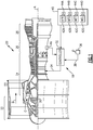
- FIG. 1 schematically illustrates an example gas turbine engine 20 that includes a fan section 22, a compressor section 24, a combustor section 26 and a turbine section 28.
- Alternative engines might include an augmenter section (not shown) among other systems or features.
- the fan section 22 drives air along a bypass flow path B while the compressor section 24 draws air in along a core flow path C where air is compressed and communicated to a combustor section 26.
- air is mixed with fuel and ignited to generate a high pressure exhaust gas stream that expands through the turbine section 28 where energy is extracted and utilized to drive the fan section 22 and the compressor section 24.
- the turbine section 28 drives a geared architecture 30 that in turn drives the fan section 22.
- the geared architecture 30 enables the turbine section 28 and the fan section 22 to each rotate at closer to optimal speeds.
- turbofan gas turbine engine depicts a turbofan gas turbine engine
- concepts described herein are not limited to use with turbofans as the teachings may be applied to other types of turbine engines; for example a turbine engine including a three-spool architecture in which three spools concentrically rotate about a common axis and where a low spool enables a low pressure turbine to drive a fan via a gearbox, an intermediate spool that enables an intermediate pressure turbine to drive a first compressor of the compressor section, and a high spool that enables a high pressure turbine to drive a high pressure compressor of the compressor section.
- other power turbine machines such as a turboshaft engine utilized in rotary wing aircraft and power generation applications.
- An engine control system 18 includes an engine controller 32 that provides an output 34 to control the gas turbine engine 20 to obtain the desired level of thrust output.
- the controller 32 is in communication with a throttle 36 and a rating schedule 40.
- the throttle 36 provides a throttle position output 38 to the controller 32 and the rating schedule 40 includes different thrust ratings that are selected for different aircraft operating conditions.
- Engine control is accomplished by monitoring engine operational characteristics with sensors 46 that provide an output to the controller 32.
- sensors 46 that provide an output to the controller 32.
- the sensor 46 provides information indicative of an engine thrust production or output.
- Thrust ratings are certified for each engine an airframe combination.
- the rating schedule is utilized to maintain a balance between providing sufficient thrust to enable operation within predetermined parameters while limiting thrust to reduce wear on the engine. Thrust production is also referred to as an engine rating and different aircraft manufacturers utilize different rating values, terms and control schemes.
- one airframe may have a takeoff (MTO) rating, a bump rating, a continuous (MCT) rating and a climb (MCL) rating while another may replace the bump rating with an auxiliary power reserve (APR) rating.
- the rating schedule includes ratings 42A-D.
- one airframe may have a takeoff (MTO) rating, a bump rating, a continuous (MCT) rating and a climb (MCL) rating while another may replace the bump rating with an auxiliary power reserve (APR) rating.
- each category of rating may further have different variations.
- engine idle ratings may include different variants for ground, flight and approach conditions.
- a cruise (MCR) rating may have been included to instruct engine operating parameters during cruise operations.
- the cruise (MCR) rating may also have variants to address different aircraft operating conditions.
- the ratings 42A-D is typically determined for a standard set of environmental conditions such as temperature and pressure. Accordingly, some adjustment is provided to enable variation from the ratings 42A-D based on environmental parameters along with aircraft payload and other aircraft variable characteristics.
- the specific derate is selected by the pilot to balance aircraft performance with engine durability. The pilot selects the desired derate based on the environment and aircraft configuration to minimize operating stresses on the engine.
- the adjustments are referred to by those skilled in the art as derate and are associated with each of the ratings 42A-D.
- each rating includes derates 44A-D. As appreciated, although two derates 44A-D are shown that correspond with each rating 42A-D, any number of derates could be associated with each rating 42A-D.
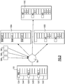
- a disclosed method provides a generic rating structure 50 that reuses a common memory and algorithm in a way that can be customized for individual airframer rating requirements.
- the generic rating structure 50 is a memory device that includes structured memory locations referred to as tables 52A-C and corresponding memory locations for derate values 54A-C.
- the example system 18 provides a generic logic set 50 that can be mapped to the desired rating.
- generic rating structures 52A-D are available.
- An input device 56 receives rating information schematically indicated at 58A-C and assigns portions of the generic logic structure 50 to receive the input rating information 58A-C.
- the generic logic structures 52A-C are mapped to the desired and selected rating structures 58A-C that include some combination of APR, MTO, MCT, MCR and MCL.
- a final rating schedule is constructed for each different airframe from the same generic rating structure 50 that is mapped to the different set of ratings 58A-C. Accordingly, final rating schedules 60A-C are generated to include the desired combination of APR, BUMP, MTO, MCT and MCL.
- the final rating schedules 60A may not include all possible ratings, one customer may utilize APR and MTO, while yet another customer may utilize only MTO, MCT and MCL. Moreover, some ratings may require the use of different maximum thrust rating values referred to as Namplates as is shown by way of example in the rating schedule 60A. Moreover, in some completed rating schedules, some logic locations would be unused such as is indicated at 60B.
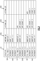
- the tables 52A-C of the generic logic structure is shown mapped to provide rating schedules 60A-C according to different airframe requirements.
- the generic tables 52A-C along with the derate A-C are present in each of the different rating schedules 60A-C, but hold different rating values and conditions that correspond with the airframe rating requirements.
- auxiliary power rating pointers 62A-C are applied to define transition between ratings.
- the auxiliary power rating is a term known in the art utilized to describe a reserve amount of thrust accommodated at each power rating.
- the APR rating changes for each rating and derate value.
- the example generic logic structure 50 enables adaptation to different fixed rate transitions as indicated at 64A. In the example show in Figure 4 , there are many defined fixed derate transitions 64A defined for the rating schedule 60A. Additionally, a nameplate selector 66A is enabled for selecting which of the ratings will provide the maximum engine thrust. In most rating schedules only a single nameplate is selected, however the disclosed generic logic structure 50 enables adaptations to include several nameplate selection as is indicated in Figure 4 .
- the rating schedules 60B and 60C do not utilize all of the tables 52A-C in the generic structure 50 as not all of the space is required to accommodate the different requirements. Moreover, the placement of each rating value can be within any of the tables 52A-C and is not constrained with beginning with the first available table such as for example 52A. Moreover the APR pointers 62B and 62C may not all be utilized. In the rating schedules 60B and 60C, only a single Namplate selector 66B and 66C are utilized and shown.
- the example method is performed on the system 18 or another computing device such as microprocessor or the disclosed controller 32.
- the controller can include a processor, a memory, and one or more input and/or output (I/O) device interface(s) that are communicatively coupled via a local interface.
- the local interface can include, for example but not limited to, one or more buses and/or other wired or wireless connections.
- the local interface may have additional elements, which are omitted for simplicity, such as controllers, buffers (caches), drivers, repeaters, and receivers to enable communications. Further, the local interface may include address, control, and/or data connections to enable appropriate communications among the aforementioned components.
- the processor may be a hardware device for executing software, particularly software stored in memory.
- the processor can be a custom made or commercially available processor, a central processing unit (CPU), an auxiliary processor among several processors associated with the computing device, a semiconductor based microprocessor (in the form of a microchip or chip set) or generally any device for executing software instructions.
- the completed rating schedule 40 can be stored in a memory and that the memory can include any one or combination of volatile memory elements (e.g., random access memory (RAM, such as DRAM, SRAM, SDRAM, VRAM, etc.)) and/or nonvolatile memory elements (e.g., ROM, hard drive, tape, CD-ROM, etc.). Moreover, the memory may incorporate electronic, magnetic, optical, and/or other types of storage media. Note that the memory can also have a distributed architecture, where various components are situated remotely from one another, but can be accessed by the processor.
- RAM random access memory
- SRAM static random access memory
- SDRAM Secure Digital RAM
- VRAM electrically programmable read-only memory
- the memory may incorporate electronic, magnetic, optical, and/or other types of storage media. Note that the memory can also have a distributed architecture, where various components are situated remotely from one another, but can be accessed by the processor.
- the software in the memory may include one or more separate programs, each of which includes an ordered listing of executable instructions for implementing logical functions.
- a system component embodied as software may also be construed as a source program, executable program (object code), script, or any other entity comprising a set of instructions to be performed.
- the program is translated via a compiler, assembler, interpreter, or the like, which may or may not be included within the memory.
- the Input/Output devices that may be coupled to system I/O Interface(s) may include input devices, for example but not limited to, a keyboard, mouse, scanner, microphone, camera, proximity device, etc. Further, the Input/Output devices may also include output devices, for example but not limited to, a printer, display, etc. Finally, the Input/Output devices may further include devices that communicate both as inputs and outputs, for instance but not limited to, a modulator/demodulator (modem; for accessing another device, system, or network), a radio frequency (RF) or other transceiver, a telephonic interface, a bridge, a router, etc.
- modem for accessing another device, system, or network
- RF radio frequency
- the processor can be configured to execute software stored within the memory, to communicate data to and from the memory, and to generally control operations pursuant to the software and to the rating schedule 40.
- Software in memory, in whole or in part, is read by the processor, perhaps buffered within the processor, and then executed.
- the system 18 and controller 32 utilizes the generated rating schedule 40 to control operation of the engine 20 and provide the desired thrust and performance while mitigating unnecessary wear extend engine operational life.
- the disclosed system and method provides a generic framework for ratings combined with simple selection logic to customize rating schedules for multiple airframe customers. This reduces software design effort, reduces memory consumption, and reduces processor throughput.
Landscapes
- Engineering & Computer Science (AREA)
- Combustion & Propulsion (AREA)
- Chemical & Material Sciences (AREA)
- Business, Economics & Management (AREA)
- Physics & Mathematics (AREA)
- General Physics & Mathematics (AREA)
- General Engineering & Computer Science (AREA)
- Human Resources & Organizations (AREA)
- Mechanical Engineering (AREA)
- Economics (AREA)
- Entrepreneurship & Innovation (AREA)
- Strategic Management (AREA)
- Automation & Control Theory (AREA)
- Tourism & Hospitality (AREA)
- General Business, Economics & Management (AREA)
- Quality & Reliability (AREA)
- Theoretical Computer Science (AREA)
- Operations Research (AREA)
- Marketing (AREA)
- Game Theory and Decision Science (AREA)
- Educational Administration (AREA)
- Development Economics (AREA)
- Fluid Mechanics (AREA)
- Control Of Turbines (AREA)
Description
- This application claims priority to United States Provisional Application No.
61/708,353 filed on October 1, 2012 - A gas turbine engine typically includes a fan section, a compressor section, a combustor section and a turbine section. Air entering the compressor section is compressed and delivered into the combustion section where it is mixed with fuel and ignited to generate a high-speed exhaust gas flow. The high-speed exhaust gas flow expands through the turbine section to drive the compressor and the fan section.
- Operation of the gas turbine engine is controlled according to schedule of thrust settings. Engine operating parameters are modified and adjusted to provide the desired thrust setting according to the schedule. Different thrust settings are defined according to the schedule for different aircraft operating periods, such as for takeoff, climb, cruise and landing. Each operational period includes a different schedule of engine thrust, also referred to as a rating. Within each operating period adjustments are made to account for variations in temperature, pressure, altitude, aircraft weight and many other variable factors.
- Moreover, each airframe manufacturer defines the desired thrust or rating schedule for each operating condition. Further, each airframe manufacturer may also require different rating schedules for different parts of the operating sequence from take-off to landing. The rating schedules are defined as part of an engine control program and are typically uniquely constructed for each engine and/or aircraft platform. Development of control programs can be costly and time intensive and therefore it is desirable to design a system that could be utilized for many different engine and aircraft platforms.
-
US 2012/124965A1 relates to a variable area fan nozzle fan flutter management system. - A method of defining a rating schedule for a gas turbine engine according to an exemplary embodiment of this disclosure, among other possible things includes defining a plurality of generic rating structures adapted to receive corresponding groups of rating information, determining a set of desired ratings for a selected gas turbine engine, mapping each of the set the desired ratings to a corresponding one of the plurality of generic rating structures, generating a unique rating structure including the desired ratings mapped to the generic rating structure, and loading the generated unique rating structure into a controller that is configured to control the selected gas turbine engine according to the unique rating structure.
- In a further embodiment of the foregoing method, the desired ratings include engine thrust levels for specific operational conditions.
- In a further embodiment of any of the foregoing methods, includes defining a derate schedule for at least one of the generated unique rating structure and loading the derate schedule into the controller to correspond with the corresponding unique rating structure.
- In a further embodiment of any of the foregoing methods, at least one of the ratings includes auxiliary power (APR) rating.
- In a further embodiment of any of the foregoing methods, at least one of the desired ratings includes a take-off (MTO) power rating.
- In a further embodiment of any of the foregoing methods, at least one of the desired ratings includes a continuous (MCT) power rating.
- In a further embodiment of any of the foregoing methods, at least one of the desired ratings includes a climb power (MCL) rating.
- In a further embodiment of any of the foregoing methods, at least one of the desired ratings includes a cruse power (MCR) rating.
- In a further embodiment of any of the foregoing methods, includes a derate value for adjusting the desired rating.
- In a further embodiment of any of the foregoing methods, includes a pointer for designating an auxiliary power rating for a desired power rating.
- A system for operating a gas turbine engine according to an exemplary embodiment of this disclosure, among other possible things includes a plurality of generic rating structures adapted to receive corresponding groups of rating information, an input for receiving rating information for a selected gas turbine engine and for assigning the received rating information to one of the plurality of generic rating structures, and a controller for accessing the groups of rating information and for producing an output communicating for controlling the gas turbine engine to produce thrust corresponding to the rating information.
- In a further embodiment of the foregoing system, the generic rating structures define logic structures for accepting rating values corresponding to the selected gas turbine engine.
- In a further embodiment of any of the foregoing systems, the plurality of generic rating structures includes a corresponding plurality of generic derate structures for accepting information relating to adjusting the rating information responsive to selected operating conditions.
- In a further embodiment of any of the foregoing systems, the received rating information includes a takeoff rating.
- In a further embodiment of any of the foregoing systems, the received rating information includes a bump rating.
- In a further embodiment of any of the foregoing systems, the received rating information includes a continuous rating.
- In a further embodiment of any of the foregoing systems, the received rating information includes an auxiliary power rating.
- In a further embodiment of any of the foregoing systems, includes a throttle input representing a desired thrust communicating with the controller such that the controller modifies the output for controlling the gas turbine engine responsive to the throttle input.
- Although the different examples have the specific components shown in the illustrations, embodiments of this disclosure are not limited to those particular combinations. It is possible to use some of the components or features from one of the examples in combination with features or components from another one of the examples.
- These and other features disclosed herein can be best understood from the following specification and drawings, the following of which is a brief description.
-
-
Figure 1 is a schematic view of an example gas turbine engine. -
Figure 2 is a schematic view of an example method of mapping ratings to a generic logic structure. -
Figure 3 is a table illustrating different mapped ratings to a common generic logic structure. -
Figure 4 is a table illustrating one example rating schedule mapped to the generic logic structure. -
Figure 5 is another table illustrating another example rating schedule mapped to the generic logic structure. -
Figure 6 is another table illustrating another example rating schedule mapped to the generic logic structure. -
Figure 1 schematically illustrates an examplegas turbine engine 20 that includes afan section 22, acompressor section 24, acombustor section 26 and aturbine section 28. Alternative engines might include an augmenter section (not shown) among other systems or features. Thefan section 22 drives air along a bypass flow path B while thecompressor section 24 draws air in along a core flow path C where air is compressed and communicated to acombustor section 26. In thecombustor section 26, air is mixed with fuel and ignited to generate a high pressure exhaust gas stream that expands through theturbine section 28 where energy is extracted and utilized to drive thefan section 22 and thecompressor section 24. In this example theturbine section 28 drives a gearedarchitecture 30 that in turn drives thefan section 22. The gearedarchitecture 30 enables theturbine section 28 and thefan section 22 to each rotate at closer to optimal speeds. - Although the disclosed non-limiting embodiment depicts a turbofan gas turbine engine, it should be understood that the concepts described herein are not limited to use with turbofans as the teachings may be applied to other types of turbine engines; for example a turbine engine including a three-spool architecture in which three spools concentrically rotate about a common axis and where a low spool enables a low pressure turbine to drive a fan via a gearbox, an intermediate spool that enables an intermediate pressure turbine to drive a first compressor of the compressor section, and a high spool that enables a high pressure turbine to drive a high pressure compressor of the compressor section. Moreover other power turbine machines such as a turboshaft engine utilized in rotary wing aircraft and power generation applications.
- An
engine control system 18 includes anengine controller 32 that provides anoutput 34 to control thegas turbine engine 20 to obtain the desired level of thrust output. Thecontroller 32 is in communication with athrottle 36 and arating schedule 40. Thethrottle 36 provides athrottle position output 38 to thecontroller 32 and therating schedule 40 includes different thrust ratings that are selected for different aircraft operating conditions. - Engine control is accomplished by monitoring engine operational characteristics with
sensors 46 that provide an output to thecontroller 32. As appreciated, a plurality of different sensors throughout the engine are utilized and schematically represented by thesensor 46. Thesensor 46 provides information indicative of an engine thrust production or output. - Each engine will include several different engine thrust levels that correspond to different part of aircraft operation such as take-off, cruise or landing. Thrust ratings are certified for each engine an airframe combination. The rating schedule is utilized to maintain a balance between providing sufficient thrust to enable operation within predetermined parameters while limiting thrust to reduce wear on the engine. Thrust production is also referred to as an engine rating and different aircraft manufacturers utilize different rating values, terms and control schemes. For example, one airframe may have a takeoff (MTO) rating, a bump rating, a continuous (MCT) rating and a climb (MCL) rating while another may replace the bump rating with an auxiliary power reserve (APR) rating. In this example, the rating schedule includes
ratings 42A-D. Moreover, one airframe may have a takeoff (MTO) rating, a bump rating, a continuous (MCT) rating and a climb (MCL) rating while another may replace the bump rating with an auxiliary power reserve (APR) rating. - Additionally, each category of rating may further have different variations. For example, engine idle ratings may include different variants for ground, flight and approach conditions. Moreover, a cruise (MCR) rating may have been included to instruct engine operating parameters during cruise operations. The cruise (MCR) rating may also have variants to address different aircraft operating conditions.
- The
ratings 42A-D is typically determined for a standard set of environmental conditions such as temperature and pressure. Accordingly, some adjustment is provided to enable variation from theratings 42A-D based on environmental parameters along with aircraft payload and other aircraft variable characteristics. The specific derate is selected by the pilot to balance aircraft performance with engine durability. The pilot selects the desired derate based on the environment and aircraft configuration to minimize operating stresses on the engine. The adjustments are referred to by those skilled in the art as derate and are associated with each of theratings 42A-D. In this example each rating includes derates 44A-D. As appreciated, although twoderates 44A-D are shown that correspond with eachrating 42A-D, any number of derates could be associated with eachrating 42A-D. - Because each aircraft manufacturer utilizes different ratings, engines controls and rating schedules are different. Therefore one rating schedule and control logic cannot accommodate all potential combinations. Simply constructing a common logic structure with ratings for all aircraft manufactures is inefficient and memory intensive.
- Referring to
Figure 2 with continued reference toFigure 1 , a disclosed method provides ageneric rating structure 50 that reuses a common memory and algorithm in a way that can be customized for individual airframer rating requirements. In this example thegeneric rating structure 50 is a memory device that includes structured memory locations referred to as tables 52A-C and corresponding memory locations for derate values 54A-C. - Accordingly, the
example system 18 provides a generic logic set 50 that can be mapped to the desired rating. For example, instead of having APR, MTO, MCT and MCL ratings,generic rating structures 52A-D are available. Aninput device 56 receives rating information schematically indicated at 58A-C and assigns portions of thegeneric logic structure 50 to receive theinput rating information 58A-C. - Therefore, for a given airframe customer, the
generic logic structures 52A-C are mapped to the desired and selectedrating structures 58A-C that include some combination of APR, MTO, MCT, MCR and MCL. A final rating schedule is constructed for each different airframe from the samegeneric rating structure 50 that is mapped to the different set ofratings 58A-C. Accordingly, final rating schedules 60A-C are generated to include the desired combination of APR, BUMP, MTO, MCT and MCL. - The
final rating schedules 60A may not include all possible ratings, one customer may utilize APR and MTO, while yet another customer may utilize only MTO, MCT and MCL. Moreover, some ratings may require the use of different maximum thrust rating values referred to as Namplates as is shown by way of example in therating schedule 60A. Moreover, in some completed rating schedules, some logic locations would be unused such as is indicated at 60B. - Referring to
Figure 3 , the tables 52A-C of the generic logic structure is shown mapped to providerating schedules 60A-C according to different airframe requirements. The generic tables 52A-C along with the derate A-C are present in each of thedifferent rating schedules 60A-C, but hold different rating values and conditions that correspond with the airframe rating requirements. - Referring to
Figures 4 ,5 and6 , along with the different rating structures that are generated from the common logic structure different auxiliarypower rating pointers 62A-C are applied to define transition between ratings. As is schematically shown inFigure 4 , the auxiliary power rating is a term known in the art utilized to describe a reserve amount of thrust accommodated at each power rating. Like the thrust ratings, the APR rating changes for each rating and derate value. The examplegeneric logic structure 50 enables adaptation to different fixed rate transitions as indicated at 64A. In the example show inFigure 4 , there are many defined fixedderate transitions 64A defined for therating schedule 60A. Additionally, anameplate selector 66A is enabled for selecting which of the ratings will provide the maximum engine thrust. In most rating schedules only a single nameplate is selected, however the disclosedgeneric logic structure 50 enables adaptations to include several nameplate selection as is indicated inFigure 4 . - Referring to
Figures 5 and6 , different rating schedule are illustrated in comparison to theoriginal data structure 50. The rating schedules 60B and 60C do not utilize all of the tables 52A-C in thegeneric structure 50 as not all of the space is required to accommodate the different requirements. Moreover, the placement of each rating value can be within any of the tables 52A-C and is not constrained with beginning with the first available table such as for example 52A. Moreover theAPR pointers single Namplate selector - It should be understood that three tables 52A-C and three
derates 54A-C for each of the tables 52A-C are shown by way of example, but any number of tables, and derates are within the contemplation of this disclosure to provide the generic logic structure capable of receiving information for any number of combination of rating settings and requirements. - Moreover, the example method is performed on the
system 18 or another computing device such as microprocessor or the disclosedcontroller 32. In terms of hardware architecture, the controller can include a processor, a memory, and one or more input and/or output (I/O) device interface(s) that are communicatively coupled via a local interface. The local interface can include, for example but not limited to, one or more buses and/or other wired or wireless connections. The local interface may have additional elements, which are omitted for simplicity, such as controllers, buffers (caches), drivers, repeaters, and receivers to enable communications. Further, the local interface may include address, control, and/or data connections to enable appropriate communications among the aforementioned components. - The processor may be a hardware device for executing software, particularly software stored in memory. The processor can be a custom made or commercially available processor, a central processing unit (CPU), an auxiliary processor among several processors associated with the computing device, a semiconductor based microprocessor (in the form of a microchip or chip set) or generally any device for executing software instructions.
- Moreover, the completed
rating schedule 40, can be stored in a memory and that the memory can include any one or combination of volatile memory elements (e.g., random access memory (RAM, such as DRAM, SRAM, SDRAM, VRAM, etc.)) and/or nonvolatile memory elements (e.g., ROM, hard drive, tape, CD-ROM, etc.). Moreover, the memory may incorporate electronic, magnetic, optical, and/or other types of storage media. Note that the memory can also have a distributed architecture, where various components are situated remotely from one another, but can be accessed by the processor. - The software in the memory may include one or more separate programs, each of which includes an ordered listing of executable instructions for implementing logical functions. A system component embodied as software may also be construed as a source program, executable program (object code), script, or any other entity comprising a set of instructions to be performed. When constructed as a source program, the program is translated via a compiler, assembler, interpreter, or the like, which may or may not be included within the memory.
- The Input/Output devices that may be coupled to system I/O Interface(s) may include input devices, for example but not limited to, a keyboard, mouse, scanner, microphone, camera, proximity device, etc. Further, the Input/Output devices may also include output devices, for example but not limited to, a printer, display, etc. Finally, the Input/Output devices may further include devices that communicate both as inputs and outputs, for instance but not limited to, a modulator/demodulator (modem; for accessing another device, system, or network), a radio frequency (RF) or other transceiver, a telephonic interface, a bridge, a router, etc.
- When the
controller 32 is in operation, the processor can be configured to execute software stored within the memory, to communicate data to and from the memory, and to generally control operations pursuant to the software and to therating schedule 40. Software in memory, in whole or in part, is read by the processor, perhaps buffered within the processor, and then executed. - The
system 18 andcontroller 32 utilizes the generatedrating schedule 40 to control operation of theengine 20 and provide the desired thrust and performance while mitigating unnecessary wear extend engine operational life. - The disclosed system and method provides a generic framework for ratings combined with simple selection logic to customize rating schedules for multiple airframe customers. This reduces software design effort, reduces memory consumption, and reduces processor throughput.
- Although an example embodiment has been disclosed, a worker of ordinary skill in this art would recognize that certain modifications would come within the scope of this disclosure. For that reason, the following claims should be studied to determine the scope and content of this disclosure.
Claims (14)
- A method of defining a rating schedule for an aircraft gas turbine engine characterised by:defining a plurality of generic aircraft operation rating structures (52 A-D) adapted to receive corresponding groups of rating information (58 A-C);determining a set of desired aircraft operation ratings (42 A-D) for a selected gas turbine engine, wherein the desired aircraft operation ratings include engine thrust levels for specific aircraft operational conditions;mapping each of the set the desired aircraft operation ratings to a corresponding one of the plurality of generic aircraft operation rating structures;generating a unique aircraft operation rating structure including the desired ratings mapped to the generic aircraft operation rating structures; andloading the generated unique aircraft operation rating structure into a controller that is configured to control the selected gas turbine engine according to the unique aircraft rating structure.
- The method as recited in claim 1, including defining a derate schedule for at least one of the generated unique rating structure and loading the derate schedule into the controller to correspond with the corresponding unique rating structure.
- The method as recited in any preceding claim, wherein at least one of the ratings comprises auxiliary power (APR) rating.
- The method as recited in any preceding claim, wherein at least one of the desired ratings comprises a take-off (MTO) power rating.
- The method as recited in any preceding claim, wherein at least one of the desired ratings comprises a continuous (MCT) power rating.
- The method as recited in any preceding claim, wherein at least one of the desired ratings comprises a climb power (MCL) rating.
- The method as recited in any preceding claim, wherein at least one of the desired ratings comprises a cruse power (MCR) rating.
- The method as recited in any preceding claim, including a derate value for adjusting the desired rating.
- The method as recited in any preceding claim, including a pointer for designating an auxiliary power rating for a desired power rating.
- A system for operating an aircraft gas turbine engine characterised by
a plurality of generic aircraft operation rating structures (52 A-D) adapted to receive corresponding groups of rating information (58 A-D), wherein each of the plurality of generic aircraft operation rating structures define a specific aircraft engine thrust level;
an input for receiving aircraft operation rating information for a selected gas turbine engine and for assigning the received aircraft operation rating information to one of the plurality of generic aircraft operation rating structures; and
a controller (32) for accessing the groups of rating information and for producing an output communication for controlling the gas turbine engine to produce thrust corresponding to the aircraft operation rating information. - The system as recited in claim 10, wherein the generic rating structures define logic structures (52 A-C) for accepting rating values corresponding to the selected gas turbine engine.
- The system as recited in claim 10 or 11, wherein the plurality of generic rating structures includes a corresponding plurality of generic derate structures (54 A-C) for accepting information relating to adjusting the rating information responsive to selected operating conditions.
- The system as recited in claim 10, 11, or 12, wherein the received rating information comprises one or more of a takeoff rating, a bump rating, a continuous rating, and an auxiliary power rating.
- The system as recited in any of claims 10 to 13, including a throttle input representing a desired thrust communicating with the controller such that the controller modifies the output for controlling the gas turbine engine responsive to the throttle input.
Applications Claiming Priority (2)
| Application Number | Priority Date | Filing Date | Title |
|---|---|---|---|
| US201261708353P | 2012-10-01 | 2012-10-01 | |
| PCT/US2013/032047 WO2014055124A1 (en) | 2012-10-01 | 2013-03-15 | Method of defining gas turbine engine control ratings |
Publications (3)
| Publication Number | Publication Date |
|---|---|
| EP2904251A1 EP2904251A1 (en) | 2015-08-12 |
| EP2904251A4 EP2904251A4 (en) | 2015-10-07 |
| EP2904251B1 true EP2904251B1 (en) | 2019-06-26 |
Family
ID=50435309
Family Applications (1)
| Application Number | Title | Priority Date | Filing Date |
|---|---|---|---|
| EP13843574.8A Active EP2904251B1 (en) | 2012-10-01 | 2013-03-15 | Method of defining gas turbine engine control ratings |
Country Status (3)
| Country | Link |
|---|---|
| US (2) | US9909510B2 (en) |
| EP (1) | EP2904251B1 (en) |
| WO (1) | WO2014055124A1 (en) |
Families Citing this family (5)
| Publication number | Priority date | Publication date | Assignee | Title |
|---|---|---|---|---|
| US9909510B2 (en) * | 2012-10-01 | 2018-03-06 | United Technologies Corporation | Method of defining gas turbine engine control ratings |
| US20160341179A1 (en) * | 2015-05-20 | 2016-11-24 | General Electric Company | Limit for derating scheme used in wind turbine control |
| US10946973B2 (en) | 2018-06-27 | 2021-03-16 | Honeywell International Inc. | System and method for providing end-use specific customization of gas turbine engine operation |
| US11391218B2 (en) * | 2019-03-22 | 2022-07-19 | Pratt & Whitney Canada Corp. | Method and system for setting power of an aircraft engine |
| GB2610199B (en) * | 2021-08-25 | 2024-01-17 | Rolls Royce Plc | Computer-implemented methods for enabling optimisation of derate for a propulsion system of a vehicle |
Family Cites Families (21)
| Publication number | Priority date | Publication date | Assignee | Title |
|---|---|---|---|---|
| US4275557A (en) | 1978-01-25 | 1981-06-30 | General Electric Company | Method and apparatus for controlling thrust in a gas turbine engine |
| US4313167A (en) | 1979-07-27 | 1982-01-26 | General Electric Company | Thrust control system for a gas turbine engine |
| GB2225125A (en) | 1988-11-16 | 1990-05-23 | Sundstrand Corp | Turbine monitoring system |
| US5048285A (en) | 1990-03-26 | 1991-09-17 | Untied Technologies Corporation | Control system for gas turbine engines providing extended engine life |
| US5285634A (en) | 1991-12-09 | 1994-02-15 | United Technologies Corporation | Aircraft gas turbine engine control |
| US5893040A (en) * | 1996-05-15 | 1999-04-06 | The Boeing Company | Method and apparatus for automatically providing jet engine thrust ratings to avionic systems |
| US6487490B1 (en) * | 1999-05-26 | 2002-11-26 | General Electric Company | Speed modification system for gas turbine engine to allow trimming of excess |
| US6311106B1 (en) | 2000-05-26 | 2001-10-30 | American Utilicraft Corporation | Automatic flat rate setting system for freight feeder aircraft and method of setting of engine flat rate |
| US6665606B2 (en) * | 2001-02-20 | 2003-12-16 | Cummins, Inc. | Distributed engine processing system |
| US6748744B2 (en) | 2001-11-21 | 2004-06-15 | Pratt & Whitney Canada Corp. | Method and apparatus for the engine control of output shaft speed |
| US6778884B2 (en) * | 2002-06-11 | 2004-08-17 | Honeywell International, Inc. | System and method for generating consolidated gas turbine control tables |
| US6880784B1 (en) * | 2003-05-08 | 2005-04-19 | Supersonic Aerospace International, Llc | Automatic takeoff thrust management system |
| DE10329252A1 (en) * | 2003-06-25 | 2005-01-13 | Rolls-Royce Deutschland Ltd & Co Kg | Control system for an aircraft engine |
| US7010904B2 (en) | 2003-12-05 | 2006-03-14 | United Technologies Corporation | Method for control scheduling to achieve linear thrust response |
| US7603222B2 (en) * | 2005-11-18 | 2009-10-13 | General Electric Company | Sensor diagnostics using embedded model quality parameters |
| US7949440B2 (en) * | 2006-12-22 | 2011-05-24 | Embraer-Empresa Brasileira De Aeronautica S.A. | Aircraft cruise speed control |
| US9074531B2 (en) | 2008-03-05 | 2015-07-07 | United Technologies Corporation | Variable area fan nozzle fan flutter management system |
| US8682562B2 (en) | 2009-05-08 | 2014-03-25 | Rolls-Royce Corporation | Turbine engine thrust scheduling |
| US8892264B2 (en) * | 2009-10-23 | 2014-11-18 | Viridity Energy, Inc. | Methods, apparatus and systems for managing energy assets |
| EP2520863B1 (en) | 2011-05-05 | 2016-11-23 | General Electric Technology GmbH | Method for protecting a gas turbine engine against high dynamical process values and gas turbine engine for conducting said method |
| US9909510B2 (en) * | 2012-10-01 | 2018-03-06 | United Technologies Corporation | Method of defining gas turbine engine control ratings |
-
2013
- 2013-03-15 US US14/430,589 patent/US9909510B2/en active Active
- 2013-03-15 EP EP13843574.8A patent/EP2904251B1/en active Active
- 2013-03-15 WO PCT/US2013/032047 patent/WO2014055124A1/en active Application Filing
-
2018
- 2018-02-20 US US15/899,486 patent/US10808629B2/en active Active
Non-Patent Citations (1)
| Title |
|---|
| None * |
Also Published As
| Publication number | Publication date |
|---|---|
| WO2014055124A1 (en) | 2014-04-10 |
| EP2904251A4 (en) | 2015-10-07 |
| US9909510B2 (en) | 2018-03-06 |
| US20180238243A1 (en) | 2018-08-23 |
| US10808629B2 (en) | 2020-10-20 |
| US20150275767A1 (en) | 2015-10-01 |
| EP2904251A1 (en) | 2015-08-12 |
Similar Documents
| Publication | Publication Date | Title |
|---|---|---|
| US10808629B2 (en) | Method of defining gas turbine engine control ratings | |
| US11651695B2 (en) | Engine load model systems and methods | |
| CA2852299C (en) | Engine operations support systems and methods for reducing fuel flow | |
| US20190222153A1 (en) | Lifing and performance optimization limit management for turbine engine | |
| RU2608802C2 (en) | System and method for auto configuration of fuel combustion system of gas turbine | |
| EP2809923B1 (en) | Gas turbine engine variable area fan nozzle control | |
| JP2017078421A (en) | Thrust scheduling method for variable pitch fan engines and turbo-shaft, turbo-propeller engines | |
| EP3550127B1 (en) | Systems and methods for power turbine governing | |
| CN107667367A (en) | Aircraft package system | |
| CN107807617B (en) | Improved aircraft control based on fuel, time and cost of loss | |
| EP3199783A1 (en) | Setting control for gas turbine engine component(s) | |
| Connolly et al. | Advanced control considerations for turbofan engine design | |
| RU2654552C2 (en) | Method and device for generating fuel flow rate command for injecting to combustion chamber of turbine engine | |
| US20200047905A1 (en) | Distributed control and monitoring system for multiple platforms | |
| US10490090B2 (en) | Method and device for adjusting performance variables of an aircraft | |
| CN110199102B (en) | Gas turbine engine fuel control system and method | |
| US11036883B2 (en) | Data filtering for data request workflow system | |
| US20030176954A1 (en) | Tracking and control of gas turbine engine component damage/life | |
| CN116714770A (en) | Method and apparatus for controlling an electric machine operating with a turbine engine | |
| Csank et al. | Application of the tool for turbine engine closed-loop transient analysis (TTECTrA) for dynamic systems analysis | |
| US10607426B2 (en) | Aircraft fleet and engine service policy configuration | |
| US20230296057A1 (en) | Methods and systems for controlling an engine system of a vehicle | |
| US12079221B2 (en) | Data request workflow system | |
| Gurevich et al. | Application of “Virtual” Controllers for Integrated Propulsion and Aircraft Control | |
| Kurzke et al. | Engines |
Legal Events
| Date | Code | Title | Description |
|---|---|---|---|
| PUAI | Public reference made under article 153(3) epc to a published international application that has entered the european phase |
Free format text: ORIGINAL CODE: 0009012 |
|
| 17P | Request for examination filed |
Effective date: 20150428 |
|
| AK | Designated contracting states |
Kind code of ref document: A1 Designated state(s): AL AT BE BG CH CY CZ DE DK EE ES FI FR GB GR HR HU IE IS IT LI LT LU LV MC MK MT NL NO PL PT RO RS SE SI SK SM TR |
|
| AX | Request for extension of the european patent |
Extension state: BA ME |
|
| RA4 | Supplementary search report drawn up and despatched (corrected) |
Effective date: 20150904 |
|
| RIC1 | Information provided on ipc code assigned before grant |
Ipc: G06Q 10/00 20120101ALI20150831BHEP Ipc: F02K 99/00 20090101ALI20150831BHEP Ipc: F02C 9/00 20060101ALI20150831BHEP Ipc: F02C 7/00 20060101ALI20150831BHEP Ipc: F02K 3/00 20060101AFI20150831BHEP |
|
| DAX | Request for extension of the european patent (deleted) | ||
| RAP1 | Party data changed (applicant data changed or rights of an application transferred) |
Owner name: UNITED TECHNOLOGIES CORPORATION |
|
| STAA | Information on the status of an ep patent application or granted ep patent |
Free format text: STATUS: EXAMINATION IS IN PROGRESS |
|
| 17Q | First examination report despatched |
Effective date: 20180123 |
|
| REG | Reference to a national code |
Ref country code: DE Ref legal event code: R079 Ref document number: 602013057217 Country of ref document: DE Free format text: PREVIOUS MAIN CLASS: F02K0003000000 Ipc: G06Q0010060000 |
|
| GRAP | Despatch of communication of intention to grant a patent |
Free format text: ORIGINAL CODE: EPIDOSNIGR1 |
|
| STAA | Information on the status of an ep patent application or granted ep patent |
Free format text: STATUS: GRANT OF PATENT IS INTENDED |
|
| RIC1 | Information provided on ipc code assigned before grant |
Ipc: F02C 9/00 20060101ALI20181130BHEP Ipc: G06Q 10/06 20120101AFI20181130BHEP |
|
| INTG | Intention to grant announced |
Effective date: 20190109 |
|
| GRAS | Grant fee paid |
Free format text: ORIGINAL CODE: EPIDOSNIGR3 |
|
| GRAA | (expected) grant |
Free format text: ORIGINAL CODE: 0009210 |
|
| STAA | Information on the status of an ep patent application or granted ep patent |
Free format text: STATUS: THE PATENT HAS BEEN GRANTED |
|
| AK | Designated contracting states |
Kind code of ref document: B1 Designated state(s): AL AT BE BG CH CY CZ DE DK EE ES FI FR GB GR HR HU IE IS IT LI LT LU LV MC MK MT NL NO PL PT RO RS SE SI SK SM TR |
|
| REG | Reference to a national code |
Ref country code: GB Ref legal event code: FG4D |
|
| REG | Reference to a national code |
Ref country code: CH Ref legal event code: EP |
|
| REG | Reference to a national code |
Ref country code: AT Ref legal event code: REF Ref document number: 1149168 Country of ref document: AT Kind code of ref document: T Effective date: 20190715 |
|
| REG | Reference to a national code |
Ref country code: DE Ref legal event code: R096 Ref document number: 602013057217 Country of ref document: DE |
|
| REG | Reference to a national code |
Ref country code: IE Ref legal event code: FG4D |
|
| REG | Reference to a national code |
Ref country code: NL Ref legal event code: MP Effective date: 20190626 |
|
| PG25 | Lapsed in a contracting state [announced via postgrant information from national office to epo] |
Ref country code: LT Free format text: LAPSE BECAUSE OF FAILURE TO SUBMIT A TRANSLATION OF THE DESCRIPTION OR TO PAY THE FEE WITHIN THE PRESCRIBED TIME-LIMIT Effective date: 20190626 Ref country code: HR Free format text: LAPSE BECAUSE OF FAILURE TO SUBMIT A TRANSLATION OF THE DESCRIPTION OR TO PAY THE FEE WITHIN THE PRESCRIBED TIME-LIMIT Effective date: 20190626 Ref country code: SE Free format text: LAPSE BECAUSE OF FAILURE TO SUBMIT A TRANSLATION OF THE DESCRIPTION OR TO PAY THE FEE WITHIN THE PRESCRIBED TIME-LIMIT Effective date: 20190626 Ref country code: NO Free format text: LAPSE BECAUSE OF FAILURE TO SUBMIT A TRANSLATION OF THE DESCRIPTION OR TO PAY THE FEE WITHIN THE PRESCRIBED TIME-LIMIT Effective date: 20190926 Ref country code: FI Free format text: LAPSE BECAUSE OF FAILURE TO SUBMIT A TRANSLATION OF THE DESCRIPTION OR TO PAY THE FEE WITHIN THE PRESCRIBED TIME-LIMIT Effective date: 20190626 Ref country code: AL Free format text: LAPSE BECAUSE OF FAILURE TO SUBMIT A TRANSLATION OF THE DESCRIPTION OR TO PAY THE FEE WITHIN THE PRESCRIBED TIME-LIMIT Effective date: 20190626 |
|
| REG | Reference to a national code |
Ref country code: LT Ref legal event code: MG4D |
|
| PG25 | Lapsed in a contracting state [announced via postgrant information from national office to epo] |
Ref country code: BG Free format text: LAPSE BECAUSE OF FAILURE TO SUBMIT A TRANSLATION OF THE DESCRIPTION OR TO PAY THE FEE WITHIN THE PRESCRIBED TIME-LIMIT Effective date: 20190926 Ref country code: LV Free format text: LAPSE BECAUSE OF FAILURE TO SUBMIT A TRANSLATION OF THE DESCRIPTION OR TO PAY THE FEE WITHIN THE PRESCRIBED TIME-LIMIT Effective date: 20190626 Ref country code: RS Free format text: LAPSE BECAUSE OF FAILURE TO SUBMIT A TRANSLATION OF THE DESCRIPTION OR TO PAY THE FEE WITHIN THE PRESCRIBED TIME-LIMIT Effective date: 20190626 Ref country code: GR Free format text: LAPSE BECAUSE OF FAILURE TO SUBMIT A TRANSLATION OF THE DESCRIPTION OR TO PAY THE FEE WITHIN THE PRESCRIBED TIME-LIMIT Effective date: 20190927 |
|
| REG | Reference to a national code |
Ref country code: AT Ref legal event code: MK05 Ref document number: 1149168 Country of ref document: AT Kind code of ref document: T Effective date: 20190626 |
|
| PG25 | Lapsed in a contracting state [announced via postgrant information from national office to epo] |
Ref country code: EE Free format text: LAPSE BECAUSE OF FAILURE TO SUBMIT A TRANSLATION OF THE DESCRIPTION OR TO PAY THE FEE WITHIN THE PRESCRIBED TIME-LIMIT Effective date: 20190626 Ref country code: RO Free format text: LAPSE BECAUSE OF FAILURE TO SUBMIT A TRANSLATION OF THE DESCRIPTION OR TO PAY THE FEE WITHIN THE PRESCRIBED TIME-LIMIT Effective date: 20190626 Ref country code: SK Free format text: LAPSE BECAUSE OF FAILURE TO SUBMIT A TRANSLATION OF THE DESCRIPTION OR TO PAY THE FEE WITHIN THE PRESCRIBED TIME-LIMIT Effective date: 20190626 Ref country code: AT Free format text: LAPSE BECAUSE OF FAILURE TO SUBMIT A TRANSLATION OF THE DESCRIPTION OR TO PAY THE FEE WITHIN THE PRESCRIBED TIME-LIMIT Effective date: 20190626 Ref country code: PT Free format text: LAPSE BECAUSE OF FAILURE TO SUBMIT A TRANSLATION OF THE DESCRIPTION OR TO PAY THE FEE WITHIN THE PRESCRIBED TIME-LIMIT Effective date: 20191028 Ref country code: NL Free format text: LAPSE BECAUSE OF FAILURE TO SUBMIT A TRANSLATION OF THE DESCRIPTION OR TO PAY THE FEE WITHIN THE PRESCRIBED TIME-LIMIT Effective date: 20190626 Ref country code: CZ Free format text: LAPSE BECAUSE OF FAILURE TO SUBMIT A TRANSLATION OF THE DESCRIPTION OR TO PAY THE FEE WITHIN THE PRESCRIBED TIME-LIMIT Effective date: 20190626 |
|
| PG25 | Lapsed in a contracting state [announced via postgrant information from national office to epo] |
Ref country code: IS Free format text: LAPSE BECAUSE OF FAILURE TO SUBMIT A TRANSLATION OF THE DESCRIPTION OR TO PAY THE FEE WITHIN THE PRESCRIBED TIME-LIMIT Effective date: 20191026 Ref country code: SM Free format text: LAPSE BECAUSE OF FAILURE TO SUBMIT A TRANSLATION OF THE DESCRIPTION OR TO PAY THE FEE WITHIN THE PRESCRIBED TIME-LIMIT Effective date: 20190626 Ref country code: IT Free format text: LAPSE BECAUSE OF FAILURE TO SUBMIT A TRANSLATION OF THE DESCRIPTION OR TO PAY THE FEE WITHIN THE PRESCRIBED TIME-LIMIT Effective date: 20190626 Ref country code: ES Free format text: LAPSE BECAUSE OF FAILURE TO SUBMIT A TRANSLATION OF THE DESCRIPTION OR TO PAY THE FEE WITHIN THE PRESCRIBED TIME-LIMIT Effective date: 20190626 |
|
| PG25 | Lapsed in a contracting state [announced via postgrant information from national office to epo] |
Ref country code: TR Free format text: LAPSE BECAUSE OF FAILURE TO SUBMIT A TRANSLATION OF THE DESCRIPTION OR TO PAY THE FEE WITHIN THE PRESCRIBED TIME-LIMIT Effective date: 20190626 |
|
| PG25 | Lapsed in a contracting state [announced via postgrant information from national office to epo] |
Ref country code: PL Free format text: LAPSE BECAUSE OF FAILURE TO SUBMIT A TRANSLATION OF THE DESCRIPTION OR TO PAY THE FEE WITHIN THE PRESCRIBED TIME-LIMIT Effective date: 20190626 Ref country code: DK Free format text: LAPSE BECAUSE OF FAILURE TO SUBMIT A TRANSLATION OF THE DESCRIPTION OR TO PAY THE FEE WITHIN THE PRESCRIBED TIME-LIMIT Effective date: 20190626 |
|
| PG25 | Lapsed in a contracting state [announced via postgrant information from national office to epo] |
Ref country code: IS Free format text: LAPSE BECAUSE OF FAILURE TO SUBMIT A TRANSLATION OF THE DESCRIPTION OR TO PAY THE FEE WITHIN THE PRESCRIBED TIME-LIMIT Effective date: 20200224 |
|
| REG | Reference to a national code |
Ref country code: DE Ref legal event code: R097 Ref document number: 602013057217 Country of ref document: DE |
|
| PLBE | No opposition filed within time limit |
Free format text: ORIGINAL CODE: 0009261 |
|
| STAA | Information on the status of an ep patent application or granted ep patent |
Free format text: STATUS: NO OPPOSITION FILED WITHIN TIME LIMIT |
|
| PG2D | Information on lapse in contracting state deleted |
Ref country code: IS |
|
| 26N | No opposition filed |
Effective date: 20200603 |
|
| PG25 | Lapsed in a contracting state [announced via postgrant information from national office to epo] |
Ref country code: SI Free format text: LAPSE BECAUSE OF FAILURE TO SUBMIT A TRANSLATION OF THE DESCRIPTION OR TO PAY THE FEE WITHIN THE PRESCRIBED TIME-LIMIT Effective date: 20190626 |
|
| PG25 | Lapsed in a contracting state [announced via postgrant information from national office to epo] |
Ref country code: MC Free format text: LAPSE BECAUSE OF FAILURE TO SUBMIT A TRANSLATION OF THE DESCRIPTION OR TO PAY THE FEE WITHIN THE PRESCRIBED TIME-LIMIT Effective date: 20190626 |
|
| REG | Reference to a national code |
Ref country code: CH Ref legal event code: PL |
|
| REG | Reference to a national code |
Ref country code: BE Ref legal event code: MM Effective date: 20200331 |
|
| PG25 | Lapsed in a contracting state [announced via postgrant information from national office to epo] |
Ref country code: LU Free format text: LAPSE BECAUSE OF NON-PAYMENT OF DUE FEES Effective date: 20200315 |
|
| PG25 | Lapsed in a contracting state [announced via postgrant information from national office to epo] |
Ref country code: LI Free format text: LAPSE BECAUSE OF NON-PAYMENT OF DUE FEES Effective date: 20200331 Ref country code: CH Free format text: LAPSE BECAUSE OF NON-PAYMENT OF DUE FEES Effective date: 20200331 Ref country code: IE Free format text: LAPSE BECAUSE OF NON-PAYMENT OF DUE FEES Effective date: 20200315 |
|
| PG25 | Lapsed in a contracting state [announced via postgrant information from national office to epo] |
Ref country code: BE Free format text: LAPSE BECAUSE OF NON-PAYMENT OF DUE FEES Effective date: 20200331 |
|
| PG25 | Lapsed in a contracting state [announced via postgrant information from national office to epo] |
Ref country code: MT Free format text: LAPSE BECAUSE OF FAILURE TO SUBMIT A TRANSLATION OF THE DESCRIPTION OR TO PAY THE FEE WITHIN THE PRESCRIBED TIME-LIMIT Effective date: 20190626 Ref country code: CY Free format text: LAPSE BECAUSE OF FAILURE TO SUBMIT A TRANSLATION OF THE DESCRIPTION OR TO PAY THE FEE WITHIN THE PRESCRIBED TIME-LIMIT Effective date: 20190626 |
|
| PG25 | Lapsed in a contracting state [announced via postgrant information from national office to epo] |
Ref country code: MK Free format text: LAPSE BECAUSE OF FAILURE TO SUBMIT A TRANSLATION OF THE DESCRIPTION OR TO PAY THE FEE WITHIN THE PRESCRIBED TIME-LIMIT Effective date: 20190626 |
|
| REG | Reference to a national code |
Ref country code: DE Ref legal event code: R081 Ref document number: 602013057217 Country of ref document: DE Owner name: RAYTHEON TECHNOLOGIES CORPORATION (N.D.GES.D.S, US Free format text: FORMER OWNER: UNITED TECHNOLOGIES CORPORATION, FARMINGTON, CONN., US |
|
| P01 | Opt-out of the competence of the unified patent court (upc) registered |
Effective date: 20230520 |
|
| PGFP | Annual fee paid to national office [announced via postgrant information from national office to epo] |
Ref country code: DE Payment date: 20240220 Year of fee payment: 12 Ref country code: GB Payment date: 20240220 Year of fee payment: 12 |
|
| PGFP | Annual fee paid to national office [announced via postgrant information from national office to epo] |
Ref country code: FR Payment date: 20240220 Year of fee payment: 12 |