EP3588293A2 - Störungsmanagementverfahren in einem netz von funkknoten, das auf einer lokalen strategie aufgebaut ist - Google Patents
Störungsmanagementverfahren in einem netz von funkknoten, das auf einer lokalen strategie aufgebaut ist Download PDFInfo
- Publication number
- EP3588293A2 EP3588293A2 EP19181840.0A EP19181840A EP3588293A2 EP 3588293 A2 EP3588293 A2 EP 3588293A2 EP 19181840 A EP19181840 A EP 19181840A EP 3588293 A2 EP3588293 A2 EP 3588293A2
- Authority
- EP
- European Patent Office
- Prior art keywords
- node
- considered
- nodes
- calculation
- faulty
- Prior art date
- Legal status (The legal status is an assumption and is not a legal conclusion. Google has not performed a legal analysis and makes no representation as to the accuracy of the status listed.)
- Pending
Links
Images


Classifications
-
- G—PHYSICS
- G06—COMPUTING OR CALCULATING; COUNTING
- G06F—ELECTRIC DIGITAL DATA PROCESSING
- G06F9/00—Arrangements for program control, e.g. control units
- G06F9/06—Arrangements for program control, e.g. control units using stored programs, i.e. using an internal store of processing equipment to receive or retain programs
- G06F9/46—Multiprogramming arrangements
- G06F9/50—Allocation of resources, e.g. of the central processing unit [CPU]
- G06F9/5061—Partitioning or combining of resources
-
- H—ELECTRICITY
- H04—ELECTRIC COMMUNICATION TECHNIQUE
- H04L—TRANSMISSION OF DIGITAL INFORMATION, e.g. TELEGRAPHIC COMMUNICATION
- H04L41/00—Arrangements for maintenance, administration or management of data switching networks, e.g. of packet switching networks
- H04L41/06—Management of faults, events, alarms or notifications
- H04L41/0654—Management of faults, events, alarms or notifications using network fault recovery
- H04L41/0668—Management of faults, events, alarms or notifications using network fault recovery by dynamic selection of recovery network elements, e.g. replacement by the most appropriate element after failure
-
- G—PHYSICS
- G06—COMPUTING OR CALCULATING; COUNTING
- G06F—ELECTRIC DIGITAL DATA PROCESSING
- G06F11/00—Error detection; Error correction; Monitoring
- G06F11/07—Responding to the occurrence of a fault, e.g. fault tolerance
- G06F11/14—Error detection or correction of the data by redundancy in operations
- G06F11/1402—Saving, restoring, recovering or retrying
- G06F11/1415—Saving, restoring, recovering or retrying at system level
- G06F11/1438—Restarting or rejuvenating
-
- G—PHYSICS
- G06—COMPUTING OR CALCULATING; COUNTING
- G06F—ELECTRIC DIGITAL DATA PROCESSING
- G06F11/00—Error detection; Error correction; Monitoring
- G06F11/07—Responding to the occurrence of a fault, e.g. fault tolerance
- G06F11/16—Error detection or correction of the data by redundancy in hardware
- G06F11/20—Error detection or correction of the data by redundancy in hardware using active fault-masking, e.g. by switching out faulty elements or by switching in spare elements
- G06F11/202—Error detection or correction of the data by redundancy in hardware using active fault-masking, e.g. by switching out faulty elements or by switching in spare elements where processing functionality is redundant
- G06F11/2023—Failover techniques
- G06F11/2033—Failover techniques switching over of hardware resources
-
- G—PHYSICS
- G06—COMPUTING OR CALCULATING; COUNTING
- G06F—ELECTRIC DIGITAL DATA PROCESSING
- G06F11/00—Error detection; Error correction; Monitoring
- G06F11/07—Responding to the occurrence of a fault, e.g. fault tolerance
- G06F11/16—Error detection or correction of the data by redundancy in hardware
- G06F11/20—Error detection or correction of the data by redundancy in hardware using active fault-masking, e.g. by switching out faulty elements or by switching in spare elements
- G06F11/202—Error detection or correction of the data by redundancy in hardware using active fault-masking, e.g. by switching out faulty elements or by switching in spare elements where processing functionality is redundant
- G06F11/2035—Error detection or correction of the data by redundancy in hardware using active fault-masking, e.g. by switching out faulty elements or by switching in spare elements where processing functionality is redundant without idle spare hardware
-
- H—ELECTRICITY
- H04—ELECTRIC COMMUNICATION TECHNIQUE
- H04L—TRANSMISSION OF DIGITAL INFORMATION, e.g. TELEGRAPHIC COMMUNICATION
- H04L41/00—Arrangements for maintenance, administration or management of data switching networks, e.g. of packet switching networks
- H04L41/06—Management of faults, events, alarms or notifications
- H04L41/0654—Management of faults, events, alarms or notifications using network fault recovery
-
- H—ELECTRICITY
- H04—ELECTRIC COMMUNICATION TECHNIQUE
- H04L—TRANSMISSION OF DIGITAL INFORMATION, e.g. TELEGRAPHIC COMMUNICATION
- H04L41/00—Arrangements for maintenance, administration or management of data switching networks, e.g. of packet switching networks
- H04L41/08—Configuration management of networks or network elements
- H04L41/085—Retrieval of network configuration; Tracking network configuration history
- H04L41/0853—Retrieval of network configuration; Tracking network configuration history by actively collecting configuration information or by backing up configuration information
- H04L41/0856—Retrieval of network configuration; Tracking network configuration history by actively collecting configuration information or by backing up configuration information by backing up or archiving configuration information
-
- H—ELECTRICITY
- H04—ELECTRIC COMMUNICATION TECHNIQUE
- H04L—TRANSMISSION OF DIGITAL INFORMATION, e.g. TELEGRAPHIC COMMUNICATION
- H04L41/00—Arrangements for maintenance, administration or management of data switching networks, e.g. of packet switching networks
- H04L41/08—Configuration management of networks or network elements
- H04L41/0893—Assignment of logical groups to network elements
-
- H—ELECTRICITY
- H04—ELECTRIC COMMUNICATION TECHNIQUE
- H04L—TRANSMISSION OF DIGITAL INFORMATION, e.g. TELEGRAPHIC COMMUNICATION
- H04L67/00—Network arrangements or protocols for supporting network services or applications
- H04L67/01—Protocols
- H04L67/10—Protocols in which an application is distributed across nodes in the network
- H04L67/1095—Replication or mirroring of data, e.g. scheduling or transport for data synchronisation between network nodes
-
- G—PHYSICS
- G06—COMPUTING OR CALCULATING; COUNTING
- G06F—ELECTRIC DIGITAL DATA PROCESSING
- G06F3/00—Input arrangements for transferring data to be processed into a form capable of being handled by the computer; Output arrangements for transferring data from processing unit to output unit, e.g. interface arrangements
- G06F3/06—Digital input from, or digital output to, record carriers, e.g. RAID, emulated record carriers or networked record carriers
- G06F3/0601—Interfaces specially adapted for storage systems
- G06F3/0628—Interfaces specially adapted for storage systems making use of a particular technique
- G06F3/0629—Configuration or reconfiguration of storage systems
- G06F3/0635—Configuration or reconfiguration of storage systems by changing the path, e.g. traffic rerouting, path reconfiguration
Definitions
- the invention relates to the field of fault management methods in a node network and the field of node network parts associated with this fault management.
- backups are performed at one or more levels, these are multilevel backups.
- the calculation can be recovered at least in part without having to be completely restarted, precisely thanks to the backups made.
- one or other of the backup levels is used to recover the calculation in part or even in majority or even almost completely.
- Distributed applications can last much longer than the average duration without failure of a network, also called MTBF of a cluster (for “Mean Time Between Failures” in English), so they are very likely to be interrupted. They generally do not have an internal fault management solution, which can then lead first to the loss of local backup data in the event of a physical failure of the calculation node, then followed by the loss of all of the advancement of the calculation caused by the loss of a single calculation node but whose local backup data can no longer be recovered.
- the different backup levels range from the most local backup to the most global backup, going from the simplest and fastest backup to the most complex, slowest and most expensive backup, also going from from the most fragile and weakest safeguard to the most robust and resilient safeguard.
- the object of the present invention is to provide a method for managing failure in a network of nodes at least partially overcoming the aforementioned drawbacks.
- the invention aims to provide a fault management method in a network of nodes improving the compromise between efficiency on the one hand and cost and complexity on the other hand, for at least one level of backup considered.
- the invention aims to provide a fault management method in a network of nodes which has an efficiency similar or comparable to that of an intermediate level backup, preferably that of the first intermediate backup, advantageously that of the second level.
- L2 for a cost and complexity similar or comparable to that of a backup of local level, advantageously those of the first level L1.
- the invention proposes to make the link between a storage medium and its node redirectable to another node, so as to be able to have the backup performed on the storage medium when the node is faulty, possibly by means of '' a copy at a neighboring node, but without having made a backup copy at the level of a neighboring node for most of the nodes which are not faulty or for all the nodes which are not faulty.
- the link between a storage medium and its node is not produced directly, but indirectly through a network element capable of reconfiguring this link to attach this storage medium to another node when the previous node becomes faulty. This network element connects several nodes to their respective storage media, each node being connected to its associated storage medium (or possibly to its associated storage media).
- the cost of the second level L2 is saved, while the ability to restart an application from the backups of the first level L1 is retained in the event of a breakdown of a computation node .
- the copy to a neighboring node traditionally carried out at the second level L2 is not here carried out during the execution of the application in a preventive manner for all the computing nodes, but only in the event of failure and only for the nodes which fail after occurrence of the breakdown.
- the copy is then made only to relaunch the application with the missing data, returned from the local backup.
- this backup of cost and complexity similar or comparable to a local backup presents the efficiency of an intermediate backup, which greatly improves the value for money of this backup.
- this backup of cost and complexity similar or comparable to a local backup having the effectiveness of an intermediate backup preferably makes it possible to replace both a conventional local backup and one or more conventional intermediate backups, by not keeping in addition that the global backup as a last resort, to manage the most severe failures, most of the failures can now be managed by the local-intermediate backup proposed by the invention, this one having the efficiency of a backup intermediate practically at the cost of a local backup.
- This backup according to the invention is used according to a local strategy.
- the link redirection mechanism between computation node and associated memory is used to recover the backup of a faulty node and attach it to a new node added for the occasion, advantageously during the same task, non-faulty nodes, and preferably not integrated into a compute blade having a faulty node, being preserved and restarted from their own local backup.
- a more global strategy would use the link redirection mechanism between the compute node and associated memory to recover the backup of a failed node and integrate it with a global backup so as to restart a new task by the resource manager.
- the present invention provides a method for managing failure in a network of nodes, comprising, for each node considered of all or part of the nodes of the network performing the same calculation: first, a step of local backup of the state of this node considered, at the level of a storage medium of this node considered, the link between this medium of storage and this node considered can be redirected from this storage medium to another node, then, if the node considered is faulty, a step of recovering the local backup of the state of this node considered, by redirecting said link between the node considered and its storage medium so as to connect said storage medium to an operational node different from the node considered, this operational node being already carrying out said calculation, the local backups of these nodes considered, used for the steps of recovery, are consistent with each other so as to correspond to the same state of this calculation, then, if at least one node considered is faulty, a step of returning said local backup of this node considered to a new additional node added to said network at the occasion of the failure of
- the invention comprises one or more of the following characteristics which can be used separately or in partial combination with one another or in total combination between them, applied to the subject of the aforementioned invention.
- all the local backups of the nodes of the same calculation blade as that of the faulty node are returned to a new calculation blade added to said network on the occasion of the failure of the node considered.
- the redirection of the link between support and node can be carried out even in the event of a major breakdown and even relatively generalized at the level of an entire computing blade, and on the other hand the new computing blade being fully operational, a new failure can happen later at the level of this new calculation blade and be managed in a similar manner by the mechanism recommended by the invention, whereas if the same calculation blade had been kept, a new failure arriving on this same blade retained calculation would have become more difficult to manage.
- the failure management method comprises, after said returning step, a step of relaunching said calculation from said local backups, during the same task as the task in which a node became faulty.
- the restart of the node considered, if it is not faulty and if it does not belong to the same calculation blade as a faulty node, is carried out at starting from the local backup of the state of this node considered, the restart of an operational node different from the node considered, if the node considered is faulty, is carried out from the recovery of the local backup of the state of this node considered by said operational node, recovery carried out via an intermediate node which is located on the same compute blade as this node considered, which is distinct from this node considered, and which is distinct from the operational node, preferably , the revival of an operational node different from the node considered, if the node considered belongs to the same compute blade as a faulty node, is carried out from the recovery of the local backup the state of this node considered by said operational node.
- the recovery of the local backup of the faulty node is carried out in a simpler and faster manner, the recovering node being very close to the faulty node.
- all the steps for relaunching nodes are synchronized with one another, so as to relaunch all of said nodes in the same calculation state.
- said redirection of said link between the node in question and its storage medium so as to connect said storage medium to said operational node is achieved by a change of switch in a switch connecting several nodes to their storage mediums.
- this redirection is carried out by a simple operation carried out at the level of a network element which is reliable and controlled.
- the recovery step changes the attachment of the storage medium of the local backup to the state of the failed node by passing through a switch to which the failed node and its backup storage medium were attached. the state of the failed node, but without going through the failed node itself.
- redirection can be performed even in the event of a complete physical failure of the faulty node.
- the change of attachment is carried out by sending a command to the switch, this command passing through one of the nodes attached to the switch through a management port.
- this switch is a PCIe switch (“Peripheral Component Interconnect express” in English).
- this switch is particularly advantageous because it is particularly suitable for being able to communicate between them peripherals without having to go through a microprocessor, therefore being able to bypass a faulty computation node for example.
- this PCIe switch makes it possible to attach the storage medium, for example a storage disk, containing the local backups of the failed computation node to another computation node. This operation is fast and does not require systematic copying of local backup data, and in particular not for non-faulty compute nodes.
- 3 to 10 nodes are attached to the same switch.
- the switch can easily manage this small group of nodes in the event of failure of a node in this small group.
- the fault management method also includes, for all or part of the nodes of the network performing the same calculation, even if no node considered is faulty, a step of global backup of all of these nodes, performed less often only the set of local backup steps for these nodes.
- the fault management method proposed by the invention makes it possible to restart the application, following a physical failure on a node, even complete, and this in most cases, starting from all local backups, more recent and less expensive, instead of having to start from remote backups which are very often significantly older, some rarer cases of failure sometimes requiring the use of remote global backup.
- the ability to recover local data from the failed compute node allows you to restart the application in most cases from the most recent local backups.
- the storage media are flash memories.
- the memories used are simple, fast and permanent.
- these flash memories are NVMe memories (“Non Volatile Memory express” in English).
- the memories used are particularly well suited for communicating with a PCIe switch (“Peripheral Component Interconnect express” in English).
- the network of calculation nodes comprises at least 1000 calculation nodes, advantageously at least 5000 calculation nodes, even more advantageously at least 10000 calculation nodes, making the fault management method according to the invention all the more interesting. Because the complete loss of a calculation in progress then becomes all the more critical as the network is large.
- the principle of fault tolerance is all the more important when an application is executed on a cluster which is made up of a larger number of compute nodes. The greater the number of processors, memories and other peripherals, the greater the probability of a failure occurring before the end of the execution.
- the applications which aim to run on this type of platform will use fault tolerance libraries which allow them to save (“checkpoint” in English) the data necessary for a restart (“restart” in English) in a state as close as possible to the state which existed just before the failure. Thus, these applications are not forced to restart the calculation from the beginning.
- the figure 1 schematically represents an example of a network part including a group of nodes and their storage media connected together by a PCIe switch, according to an embodiment of the invention, at which network part, an example of fault management method according to the invention can take place.
- This network part comprises several calculation nodes 2, three calculation nodes 21, 22 and 23, in the example of the figure 1 , as well as several storage media 3, three storage media 31, 32 and 33, in the example of the figure 1 .
- These compute nodes 2 and their storage media 3 form a group of compute nodes managed by a PCIe switch 1 connecting these compute nodes 2 to their respective storage media 3, by means of bidirectional PCIe connections 7, 8 or 9.
- These PCIe 7, 8, or 9 connections can be multi-lane PCIe connections.
- Connection 7 is a 4-way connection.
- Connection 8 is a 4-way connection.
- Connection 9 is a 2-way connection, here not yet used, each connection 9 being on one side attached to one of ports 13, 16 or 19 and remaining free on the other side.
- Each PCIe 7 connection connects one of the compute nodes 21 to 23 respectively to one of the ports 0, 2 or 8 (numbering of the electronic switch PLX 8733, but another PCIe switch can be used), respectively referenced 11, 14 or 17 on the figure 1 , of switch 1.
- Each PCIe 8 connection connects one of the storage media 31 to 33 respectively to one of the ports 1, 3 or 9, respectively referenced 12, 15 or 18 on the figure 1 , of switch 1.
- Connection 7, ports 0 and 1, respectively referenced 11 and 12 on the figure 1 , of the switch 1, the connection 8 together form a link 4 connecting the calculation node 23 to its support 33.
- connection 7 The connection 7, the ports 2 and 3, respectively referenced 14 and 15 on the figure 1 , of the switch 1, the connection 8 together form a link 5 connecting the computation node 22 to its support 32.
- the PCIe connections 7, 8 or 9 can be grouped together on a PCIe bus.
- the calculation node 23 is attached to the management or management port by default, that is to say that it is through it that the shipments go outside the group of calculation nodes 2 and the receipts from from outside the group of calculation nodes 2. In the event of failure of this calculation node 23, it is replaced by the calculation node 22 which is attached to the redundant management or management port, which calculation node 22 then becomes attached to the new management or effective management port.
- the attachment of the storage medium 31 is reconfigured, that is to say that the storage medium 31 will cease to be connected to its computation node 21 by default, but will become connected to the computation node 23 , which being attached to the default management port, will be able to send the local backup of the calculation state of the faulty calculation node 21, from the storage medium 31, to another spare calculation node outside the group of calculation nodes 21 to 23, this other calculation node then taking over the calculation task interrupted at the level of the faulty calculation node 21, from the local saving of the calculation state of the calculation node 21 raised from the storage medium 31, at during the same task as the task during which the failure occurred which caused the failure of at least one calculation node.
- port 9 (numbering of the electronic switch PLX8733, but another PCIe switch can be used) referenced 18 (on the figure 1 ), instead of remaining permanently connected to port 8 referenced 17 as before the failure of the calculation node 21, will be, at least temporarily connected to port 0 referenced 11, in order to allow the calculation node 23 to come and read, in the storage medium 31, the saved data representative of the state of calculation of the calculation node 21, just before or shortly before, its failure.
- the local backup in the storage medium 31, of the calculation state of the calculation node 21 before its failure, will be able to go back to the calculation node 23 and thus be used to restart the calculation with very good compromise between simplicity of backup and efficiency of recovery.
- calculation node 22 If it is node 23 which becomes faulty, it is first replaced by calculation node 22 as attached to the management port, and calculation node 22, as attached to the new management port, performs the operations previously carried out by the calculation node 23 if the latter had not become faulty.
- switch 1 The management of switch 1 is now described by a manual scenario clarifying and explaining the various operations to be carried out, such as for example the migration of the storage medium 31 from a faulty computing node 21 to a spare computing node 23, the transfer data, restarting the application.
- Data management on the application side is carried out by the FTI library.
- the application executed is provided in the examples of the FTI library: hdf.exe.
- This application is launched on two compute nodes. It will perform local backups, on NVMe storage disks connected to these compute nodes by the PCIe switch at regular intervals as well as a global backup on an NFS server ("Network File System" in English) in a less frequent way .
- NFS server Network File System
- a failure recovery is carried out with the local backup data of an MPI application (“Message Passing Interface” in English) of a computing node that breaks down.
- the data is recovered thanks to the migration of the storage medium from the faulty calculation node to a neighboring calculation node of the same calculation blade. These data are then transmitted to a second operational node which will resume the calculation.
- the advantage of this recovery from failure is that it allows the application to restart from the local backups of all the compute nodes. These less expensive local backups are also more recent most of the time, and at worst are only as recent as global backups. In addition, the amount of data transferred in order to resume the calculation will be lower than in the case of a restart from a global backup.
- the FTI (Fault Tolerance Interface) library in English for fault tolerance interface) will use in particular four existing main functions and four existing complementary functions.
- FI_Snapshot loads the checkpoint data and initializes the execution variables after recovery and writes the multilevel checkpoints according to their required frequencies.
- the "FTI_Snapshot ()” function can be replaced by the "FTI_Checkpoint” function and by the "FTI_Recover” function.
- FTI_Status returns the current state of the recovery flag. This state can be "0” if no checkpoint has yet been completed or successfully retrieved, "1” if at least one checkpoint has been completed or "2” if execution has been restarted from d 'an L4 level checkpoint and if "keep_last_checkpoint" was activated during the last execution.
- a new variable "SLURM_JOB_NODES_DOWN” is added. It contains a list of allocated nodes that have failed during execution of the task. By default, only the first node that becomes faulty will be listed. If the option “--no-kill (-k)" is specified, then all the nodes that have failed are listed. It is installed by the controller in the process that deletes the tasks. Each node can access it.
- SLURM_RESTART_COUNT is modified to be propagated as an environment variable for all the SLURM epilogues.
- the "job_ptr-> restart_cnt” structure will only be incremented by the "SBATCH" tasks.
- the user will code at least the functions "FTI_Init”, “FTI_Protect”, “FTI_Snapshot” and “FTI_Finalize”. Then, it will replace "MPI_COMM_WORLD” by “FTI_COMM_WORLD”, and adapt the parameters in the FTI configuration file. Then, the user can use the classic “sbatch” script with an additional option “#SBATCH --checkpoint-restart”.
- SLURM allocates to the task, as much as possible, three nodes per blade or at least the manager and standby manager nodes of the PCIe switch.
- the figure 2 schematically represents an example, of a local backup step, during the failure management method according to an embodiment of the invention.
- SLURM launches the MPI ranks.
- FTI writes checkpoint files with a frequency chosen by the user.
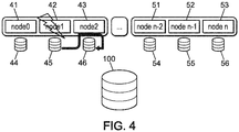
- Nodes 41 to 43 are respectively associated with storage media 44 to 46. Nodes 41 to 43 belong to the same computing blade. Nodes 51 to 53 are respectively associated with storage media 54 to 56. Nodes 51 to 53 belong to the same calculation blade different from that of nodes 41 to 43.
- Storage media 44 to 46 and 54 to 56 provide local backup of the state of their respective associated nodes 41 to 43 and 51 to 53, while a parallel file system 100 provides global backup of the state of the nodes of the network or at least of a part of the network .
- the parallel file system 100 is a network file system.
- the storage media 44 to 46 and 54 to 56 ensure local backup of the state of their respective associated nodes 41 to 43 and 51 to 53.
- the figure 3 shows schematically an example, of the occurrence of a failure, making a node faulty, during the failure management method according to an embodiment of the invention.
- SLURM detects the failure of a node and launches the epilogue which contains the update of "SLURM_JOB_DOWN_NODELIST" with the list of failed nodes, the update of "SLURM_RESTART_COUNT", and the recovery system.
- a node for example node 42 undergoes a failure (symbolized by a small flash on the figure 3 ).
- the other nodes 41 and 43 of this same calculation blade are not faulty.
- the nodes 51 to 53 of the other calculation blade are also not faulty.
- the recovery system launched during the epilogue is separated into two parts, respectively described in terms of figures 4 and 5 , during the first and second parts of a sixth stage.
- the figure 4 schematically represents an example, of a step of recovering the local backup of a faulty node, during the fault management method according to an embodiment of the invention.
- the local backup of the state of the failed node 42, performed on the storage medium 45, is duplicated on the storage medium 46 of the node 43 non-faulty, via the PCIE switch on the compute blade and via the non-faulty node 43.
- the figure 5 schematically represents an example, of the course of a duplication step, of local backups of all of the calculation nodes of a calculation blade in which a node or at least one node has failed, at the nodes of a another calculation blade added for the occasion, during the failure management method according to one embodiment of the invention.
- the storage medium 44 transmits the local backup of the non-faulty node 41 to the storage medium 64 of the node 61 of another calculation blade added for the occasion.
- the local backups of the non-faulty nodes 51 to 53 are kept locally, without being duplicated, and will be recovered by their own non-faulty nodes 51 to 53 to restart the calculation from the saved state of current calculation, during the same task as the current task which suffered the failure.
- the storage medium 46 transmits, to the storage media 65 and 66 associated with the nodes 62 and 63 of the same added computation blade and already containing the node 61, not only the local backup of the state of its associated non-faulty node 43 , but also the duplication of the local backup of the state of the faulty node 42.
- one of the supports 65 and 66 will recover the duplication of the backup of the faulty node 42 and the other that of the non-faulty node 43.
- All local backups on the supports 41 to 43 and 51 to 53 and 61 to 63, of the state of the nodes 41 to 43 and 51 to 53 and 61 to 63, respectively stored on the supports 44 and 46 and 54 to 56 and 64 to 66, are consistent with each other and correspond to the same state calculation from which this same calculation can be restarted later during the same task as the current task having suffered the failure.
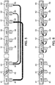
- the figure 6 schematically represents an example, of the course of a step to relaunch the calculation, from their own local backups for all the calculation blades without a faulty calculation node, and for the new calculation blades added from the duplication of the backups nodes of the calculation blades having at least one faulty node, the calculation being restarted during the same task as that during which the failure causing failure of at least one calculation node has occurred, during the failure management process according to one embodiment of the invention.
- a seventh step during the same task as the current task having undergone the breakdown, the calculation can be restarted from its last saved state, for the non-faulty nodes simply from their own local non-duplicated backups, and for the nodes belonging to a calculation blade having had a faulty node, from the duplicates of the local backups of the nodes of this calculation blade with a faulty node, duplications carried out on the nodes of a new calculation blade not yet used in the calculation and added for the occasion to this calculation, that is to say added on the occasion of the failure occurred.
- the nodes 51 to 53 not failing restart the calculation from their own backups stored on their own storage media 54 to 56.
- the nodes 41 to 43 do not restart the calculation, they are excluded from it.
- the nodes 61 to 63 of the new calculation blade added for the occasion relaunch the calculation from duplicates of backups of nodes 41 to 43 of the faulty node calculation blade, these duplicates being stored on their own storage media 64 to 66.
- ANNEX 1 IT listing used in the course of the fault management process described above.
Landscapes
- Engineering & Computer Science (AREA)
- Theoretical Computer Science (AREA)
- Computer Networks & Wireless Communication (AREA)
- Signal Processing (AREA)
- Physics & Mathematics (AREA)
- General Engineering & Computer Science (AREA)
- General Physics & Mathematics (AREA)
- Quality & Reliability (AREA)
- Software Systems (AREA)
- Hardware Redundancy (AREA)
- Data Exchanges In Wide-Area Networks (AREA)
- Information Retrieval, Db Structures And Fs Structures Therefor (AREA)
- Retry When Errors Occur (AREA)
Applications Claiming Priority (1)
| Application Number | Priority Date | Filing Date | Title |
|---|---|---|---|
| FR1855559A FR3082973B1 (fr) | 2018-06-22 | 2018-06-22 | Procede de gestion de panne dans un reseau de noeuds base sur une strategie locale |
Publications (2)
| Publication Number | Publication Date |
|---|---|
| EP3588293A2 true EP3588293A2 (de) | 2020-01-01 |
| EP3588293A3 EP3588293A3 (de) | 2020-02-26 |
Family
ID=65685418
Family Applications (1)
| Application Number | Title | Priority Date | Filing Date |
|---|---|---|---|
| EP19181840.0A Pending EP3588293A3 (de) | 2018-06-22 | 2019-06-21 | Störungsmanagementverfahren in einem netz von funkknoten, das auf einer lokalen strategie aufgebaut ist |
Country Status (5)
| Country | Link |
|---|---|
| US (1) | US11477073B2 (de) |
| EP (1) | EP3588293A3 (de) |
| JP (1) | JP2020017268A (de) |
| CN (1) | CN110635937A (de) |
| FR (1) | FR3082973B1 (de) |
Family Cites Families (8)
| Publication number | Priority date | Publication date | Assignee | Title |
|---|---|---|---|---|
| US5696895A (en) * | 1995-05-19 | 1997-12-09 | Compaq Computer Corporation | Fault tolerant multiple network servers |
| US5907849A (en) * | 1997-05-29 | 1999-05-25 | International Business Machines Corporation | Method and system for recovery in a partitioned shared nothing database system using virtual share disks |
| US7272640B1 (en) * | 2000-12-08 | 2007-09-18 | Sun Microsystems, Inc. | Dynamic network session redirector |
| US8943353B2 (en) * | 2013-01-31 | 2015-01-27 | Hewlett-Packard Development Company, L.P. | Assigning nodes to jobs based on reliability factors |
| US9619389B1 (en) * | 2013-07-11 | 2017-04-11 | Unigen Corporation | System for a backward and forward application environment compatible distributed shared coherent storage |
| US10635644B2 (en) * | 2013-11-11 | 2020-04-28 | Amazon Technologies, Inc. | Partition-based data stream processing framework |
| US9626261B2 (en) * | 2013-11-27 | 2017-04-18 | Futurewei Technologies, Inc. | Failure recovery resolution in transplanting high performance data intensive algorithms from cluster to cloud |
| US10203992B2 (en) * | 2016-05-12 | 2019-02-12 | Futurewei Technologies, Inc. | Worker node rebuild for parallel processing system |
-
2018
- 2018-06-22 FR FR1855559A patent/FR3082973B1/fr active Active
-
2019
- 2019-06-21 JP JP2019115673A patent/JP2020017268A/ja active Pending
- 2019-06-21 US US16/449,120 patent/US11477073B2/en active Active
- 2019-06-21 EP EP19181840.0A patent/EP3588293A3/de active Pending
- 2019-06-24 CN CN201910549638.3A patent/CN110635937A/zh active Pending
Also Published As
| Publication number | Publication date |
|---|---|
| CN110635937A (zh) | 2019-12-31 |
| FR3082973B1 (fr) | 2020-06-05 |
| US11477073B2 (en) | 2022-10-18 |
| US20190394085A1 (en) | 2019-12-26 |
| FR3082973A1 (fr) | 2019-12-27 |
| EP3588293A3 (de) | 2020-02-26 |
| JP2020017268A (ja) | 2020-01-30 |
Similar Documents
| Publication | Publication Date | Title |
|---|---|---|
| US11086555B1 (en) | Synchronously replicating datasets | |
| EP1529259B1 (de) | Unterbrechungsfreier betrieb durch software-replikation in einer multicomputer-architektur | |
| US9940206B2 (en) | Handling failed cluster members when replicating a database between clusters | |
| US8578144B2 (en) | Partial hibernation restore for boot time reduction | |
| US20070157016A1 (en) | Apparatus, system, and method for autonomously preserving high-availability network boot services | |
| US10216775B2 (en) | Content selection for storage tiering | |
| FR2859294A1 (fr) | Systeme de reseau de disques et procede de commande d'informations d'erreur | |
| US11221927B2 (en) | Method for the implementation of a high performance, high resiliency and high availability dual controller storage system | |
| CN1784676B (zh) | 数据库数据恢复系统和方法 | |
| FR2946769A1 (fr) | Procede et dispositif de reconfiguration d'avionique. | |
| CN101436150A (zh) | 用于复制数据到辅助存储装置上的方法和系统 | |
| CN105068836A (zh) | 一种基于sas网络的远程可共享的启动系统 | |
| JP2012507788A (ja) | ストレージ・エリア・ネットワークを使用してコンピュータシステムを復旧するための方法およびシステム | |
| EP3588294A2 (de) | Störungsmanagementverfahren in einem netz von funkknoten, das auf einer globalen strategie aufgebaut ist | |
| US10461991B1 (en) | Dynamic replication peering | |
| CN1627261A (zh) | 用于适配器快速加载的设备、系统和方法 | |
| US9075809B1 (en) | Methods and systems for application cluster virtual nodes | |
| EP3588293A2 (de) | Störungsmanagementverfahren in einem netz von funkknoten, das auf einer lokalen strategie aufgebaut ist | |
| US11226875B2 (en) | System halt event recovery | |
| FR3076004A1 (fr) | Procede de gestion de panne dans un reseau de noeuds et partie de reseau de noeuds associee | |
| US10346299B1 (en) | Reference tracking garbage collection for geographically distributed storage system | |
| US20080040368A1 (en) | Recording notations per file of changed blocks coherent with a draining agent | |
| EP3123314B1 (de) | Verfahren und vorrichtung zur steuerung der änderung in einem betriebssystem bei dienstknoten eines hochleistungscomputers | |
| US9152817B1 (en) | Methods and systems for performing data protection operations | |
| WO1997030393A1 (fr) | Systeme informatique a transparence de panne pour les applications utilisateur |
Legal Events
| Date | Code | Title | Description |
|---|---|---|---|
| PUAI | Public reference made under article 153(3) epc to a published international application that has entered the european phase |
Free format text: ORIGINAL CODE: 0009012 |
|
| STAA | Information on the status of an ep patent application or granted ep patent |
Free format text: STATUS: THE APPLICATION HAS BEEN PUBLISHED |
|
| AK | Designated contracting states |
Kind code of ref document: A2 Designated state(s): AL AT BE BG CH CY CZ DE DK EE ES FI FR GB GR HR HU IE IS IT LI LT LU LV MC MK MT NL NO PL PT RO RS SE SI SK SM TR |
|
| AX | Request for extension of the european patent |
Extension state: BA ME |
|
| PUAL | Search report despatched |
Free format text: ORIGINAL CODE: 0009013 |
|
| AK | Designated contracting states |
Kind code of ref document: A3 Designated state(s): AL AT BE BG CH CY CZ DE DK EE ES FI FR GB GR HR HU IE IS IT LI LT LU LV MC MK MT NL NO PL PT RO RS SE SI SK SM TR |
|
| AX | Request for extension of the european patent |
Extension state: BA ME |
|
| RIC1 | Information provided on ipc code assigned before grant |
Ipc: G06F 11/14 20060101ALI20200117BHEP Ipc: G06F 3/06 20060101ALI20200117BHEP Ipc: G06F 11/20 20060101ALI20200117BHEP Ipc: G06F 9/50 20060101AFI20200117BHEP |
|
| STAA | Information on the status of an ep patent application or granted ep patent |
Free format text: STATUS: REQUEST FOR EXAMINATION WAS MADE |
|
| 17P | Request for examination filed |
Effective date: 20200825 |
|
| RBV | Designated contracting states (corrected) |
Designated state(s): AL AT BE BG CH CY CZ DE DK EE ES FI FR GB GR HR HU IE IS IT LI LT LU LV MC MK MT NL NO PL PT RO RS SE SI SK SM TR |
|
| P01 | Opt-out of the competence of the unified patent court (upc) registered |
Effective date: 20230330 |
|
| RAP1 | Party data changed (applicant data changed or rights of an application transferred) |
Owner name: COMMISSARIAT A L'ENERGIE ATOMIQUE ET AUX ENERGIES ALTERNATIVES |
|
| RAP1 | Party data changed (applicant data changed or rights of an application transferred) |
Owner name: COMMISSARIAT A L'ENERGIE ATOMIQUE ET AUX ENERGIES ALTERNATIVES (CEA) Owner name: BULL SAS |
|
| RAP1 | Party data changed (applicant data changed or rights of an application transferred) |
Owner name: COMMISSARIAT A L'ENERGIE ATOMIQUE ET AUX ENERGIES ALTERNATIVES Owner name: BULL SAS |
|
| RAP3 | Party data changed (applicant data changed or rights of an application transferred) |
Owner name: COMMISSARIAT A L'ENERGIE ATOMIQUE ET AUX ENERGIESALTERNATIVES Owner name: BULL SAS |
|
| STAA | Information on the status of an ep patent application or granted ep patent |
Free format text: STATUS: EXAMINATION IS IN PROGRESS |
|
| 17Q | First examination report despatched |
Effective date: 20251017 |