EP3588231B1 - Système et procédé de détermination de la vitesse d'un giravion - Google Patents
Système et procédé de détermination de la vitesse d'un giravion Download PDFInfo
- Publication number
- EP3588231B1 EP3588231B1 EP19154943.5A EP19154943A EP3588231B1 EP 3588231 B1 EP3588231 B1 EP 3588231B1 EP 19154943 A EP19154943 A EP 19154943A EP 3588231 B1 EP3588231 B1 EP 3588231B1
- Authority
- EP
- European Patent Office
- Prior art keywords
- rotorcraft
- data
- groundspeed
- gps
- flight control
- Prior art date
- Legal status (The legal status is an assumption and is not a legal conclusion. Google has not performed a legal analysis and makes no representation as to the accuracy of the status listed.)
- Active
Links
- 238000000034 method Methods 0.000 title claims description 30
- RZVHIXYEVGDQDX-UHFFFAOYSA-N 9,10-anthraquinone Chemical compound C1=CC=C2C(=O)C3=CC=CC=C3C(=O)C2=C1 RZVHIXYEVGDQDX-UHFFFAOYSA-N 0.000 claims description 75
- 230000001133 acceleration Effects 0.000 claims description 44
- 230000000295 complement effect Effects 0.000 claims description 19
- 238000012545 processing Methods 0.000 claims description 15
- 230000004044 response Effects 0.000 claims description 9
- 125000004122 cyclic group Chemical group 0.000 description 59
- 238000005259 measurement Methods 0.000 description 16
- 238000010586 diagram Methods 0.000 description 8
- 230000008859 change Effects 0.000 description 7
- 230000033001 locomotion Effects 0.000 description 7
- 238000001914 filtration Methods 0.000 description 6
- 230000006870 function Effects 0.000 description 6
- 230000015654 memory Effects 0.000 description 6
- 238000004891 communication Methods 0.000 description 5
- 230000006641 stabilisation Effects 0.000 description 5
- 238000011105 stabilization Methods 0.000 description 5
- 230000008569 process Effects 0.000 description 4
- 230000008901 benefit Effects 0.000 description 3
- 230000005540 biological transmission Effects 0.000 description 3
- 238000013500 data storage Methods 0.000 description 3
- 238000011161 development Methods 0.000 description 3
- 230000009471 action Effects 0.000 description 2
- 230000003416 augmentation Effects 0.000 description 2
- 238000012937 correction Methods 0.000 description 2
- 230000000694 effects Effects 0.000 description 2
- 238000012935 Averaging Methods 0.000 description 1
- BXNJHAXVSOCGBA-UHFFFAOYSA-N Harmine Chemical compound N1=CC=C2C3=CC=C(OC)C=C3NC2=C1C BXNJHAXVSOCGBA-UHFFFAOYSA-N 0.000 description 1
- 230000004308 accommodation Effects 0.000 description 1
- 230000001143 conditioned effect Effects 0.000 description 1
- 238000013016 damping Methods 0.000 description 1
- 230000001419 dependent effect Effects 0.000 description 1
- 238000013461 design Methods 0.000 description 1
- 230000009977 dual effect Effects 0.000 description 1
- 230000007613 environmental effect Effects 0.000 description 1
- 238000009499 grossing Methods 0.000 description 1
- 230000007774 longterm Effects 0.000 description 1
- 239000000463 material Substances 0.000 description 1
- 238000012544 monitoring process Methods 0.000 description 1
- 230000002085 persistent effect Effects 0.000 description 1
- 230000010363 phase shift Effects 0.000 description 1
- 230000009467 reduction Effects 0.000 description 1
- 239000003381 stabilizer Substances 0.000 description 1
- 230000000087 stabilizing effect Effects 0.000 description 1
- 230000009466 transformation Effects 0.000 description 1
- 238000000844 transformation Methods 0.000 description 1
- 230000001052 transient effect Effects 0.000 description 1
- 230000007704 transition Effects 0.000 description 1
- 230000000007 visual effect Effects 0.000 description 1
Images


Classifications
-
- G—PHYSICS
- G01—MEASURING; TESTING
- G01S—RADIO DIRECTION-FINDING; RADIO NAVIGATION; DETERMINING DISTANCE OR VELOCITY BY USE OF RADIO WAVES; LOCATING OR PRESENCE-DETECTING BY USE OF THE REFLECTION OR RERADIATION OF RADIO WAVES; ANALOGOUS ARRANGEMENTS USING OTHER WAVES
- G01S19/00—Satellite radio beacon positioning systems; Determining position, velocity or attitude using signals transmitted by such systems
- G01S19/38—Determining a navigation solution using signals transmitted by a satellite radio beacon positioning system
- G01S19/39—Determining a navigation solution using signals transmitted by a satellite radio beacon positioning system the satellite radio beacon positioning system transmitting time-stamped messages, e.g. GPS [Global Positioning System], GLONASS [Global Orbiting Navigation Satellite System] or GALILEO
- G01S19/52—Determining velocity
-
- G—PHYSICS
- G05—CONTROLLING; REGULATING
- G05D—SYSTEMS FOR CONTROLLING OR REGULATING NON-ELECTRIC VARIABLES
- G05D1/00—Control of position, course, altitude or attitude of land, water, air or space vehicles, e.g. using automatic pilots
- G05D1/08—Control of attitude, i.e. control of roll, pitch, or yaw
- G05D1/0808—Control of attitude, i.e. control of roll, pitch, or yaw specially adapted for aircraft
- G05D1/0858—Control of attitude, i.e. control of roll, pitch, or yaw specially adapted for aircraft specially adapted for vertical take-off of aircraft
-
- G—PHYSICS
- G05—CONTROLLING; REGULATING
- G05D—SYSTEMS FOR CONTROLLING OR REGULATING NON-ELECTRIC VARIABLES
- G05D1/00—Control of position, course, altitude or attitude of land, water, air or space vehicles, e.g. using automatic pilots
- G05D1/10—Simultaneous control of position or course in three dimensions
- G05D1/101—Simultaneous control of position or course in three dimensions specially adapted for aircraft
-
- B—PERFORMING OPERATIONS; TRANSPORTING
- B64—AIRCRAFT; AVIATION; COSMONAUTICS
- B64C—AEROPLANES; HELICOPTERS
- B64C13/00—Control systems or transmitting systems for actuating flying-control surfaces, lift-increasing flaps, air brakes, or spoilers
- B64C13/24—Transmitting means
- B64C13/38—Transmitting means with power amplification
- B64C13/50—Transmitting means with power amplification using electrical energy
- B64C13/503—Fly-by-Wire
-
- B—PERFORMING OPERATIONS; TRANSPORTING
- B64—AIRCRAFT; AVIATION; COSMONAUTICS
- B64C—AEROPLANES; HELICOPTERS
- B64C27/00—Rotorcraft; Rotors peculiar thereto
- B64C27/04—Helicopters
- B64C27/08—Helicopters with two or more rotors
-
- G—PHYSICS
- G01—MEASURING; TESTING
- G01C—MEASURING DISTANCES, LEVELS OR BEARINGS; SURVEYING; NAVIGATION; GYROSCOPIC INSTRUMENTS; PHOTOGRAMMETRY OR VIDEOGRAMMETRY
- G01C21/00—Navigation; Navigational instruments not provided for in groups G01C1/00 - G01C19/00
- G01C21/10—Navigation; Navigational instruments not provided for in groups G01C1/00 - G01C19/00 by using measurements of speed or acceleration
- G01C21/12—Navigation; Navigational instruments not provided for in groups G01C1/00 - G01C19/00 by using measurements of speed or acceleration executed aboard the object being navigated; Dead reckoning
- G01C21/16—Navigation; Navigational instruments not provided for in groups G01C1/00 - G01C19/00 by using measurements of speed or acceleration executed aboard the object being navigated; Dead reckoning by integrating acceleration or speed, i.e. inertial navigation
-
- G—PHYSICS
- G01—MEASURING; TESTING
- G01P—MEASURING LINEAR OR ANGULAR SPEED, ACCELERATION, DECELERATION, OR SHOCK; INDICATING PRESENCE, ABSENCE, OR DIRECTION, OF MOVEMENT
- G01P5/00—Measuring speed of fluids, e.g. of air stream; Measuring speed of bodies relative to fluids, e.g. of ship, of aircraft
-
- G—PHYSICS
- G01—MEASURING; TESTING
- G01S—RADIO DIRECTION-FINDING; RADIO NAVIGATION; DETERMINING DISTANCE OR VELOCITY BY USE OF RADIO WAVES; LOCATING OR PRESENCE-DETECTING BY USE OF THE REFLECTION OR RERADIATION OF RADIO WAVES; ANALOGOUS ARRANGEMENTS USING OTHER WAVES
- G01S19/00—Satellite radio beacon positioning systems; Determining position, velocity or attitude using signals transmitted by such systems
- G01S19/01—Satellite radio beacon positioning systems transmitting time-stamped messages, e.g. GPS [Global Positioning System], GLONASS [Global Orbiting Navigation Satellite System] or GALILEO
- G01S19/13—Receivers
- G01S19/14—Receivers specially adapted for specific applications
-
- G—PHYSICS
- G01—MEASURING; TESTING
- G01S—RADIO DIRECTION-FINDING; RADIO NAVIGATION; DETERMINING DISTANCE OR VELOCITY BY USE OF RADIO WAVES; LOCATING OR PRESENCE-DETECTING BY USE OF THE REFLECTION OR RERADIATION OF RADIO WAVES; ANALOGOUS ARRANGEMENTS USING OTHER WAVES
- G01S19/00—Satellite radio beacon positioning systems; Determining position, velocity or attitude using signals transmitted by such systems
- G01S19/38—Determining a navigation solution using signals transmitted by a satellite radio beacon positioning system
- G01S19/39—Determining a navigation solution using signals transmitted by a satellite radio beacon positioning system the satellite radio beacon positioning system transmitting time-stamped messages, e.g. GPS [Global Positioning System], GLONASS [Global Orbiting Navigation Satellite System] or GALILEO
- G01S19/42—Determining position
- G01S19/43—Determining position using carrier phase measurements, e.g. kinematic positioning; using long or short baseline interferometry
Definitions
- Fly-by-wire systems in aircraft use electronic signals to control the flight surfaces and engines in the aircraft.
- the pilot controls are electronically linked to a flight computer, which, in turn, controls flight surface actuators via electronic signals.
- sophisticated control algorithms may be used to provide autopilot functionality, as well as to stabilize and control the aircraft.
- fly-by-wire systems have become commonplace in commercial and civilian fixed wing aircraft, their adoption among rotorcraft, such as helicopters, has been much slower. However, by adopting fly-by-wire systems in helicopters, safer operation may be achieved in difficult flight environments such as low speed, low altitude, degraded visual environments and inclement weather. Another area in which fly-by-wire systems may benefit rotorcraft is in the reduction in pilot workload. By providing automated features such as stabilization in response to wind, control axis decoupling, position hold and heading hold functionality, the pilot is freed up to focus on the environment in which he or she flies.
- US2007/0010920 A1 discloses an automatic piloting device utilizing a measurement of ground speed deduced from the measurements of acceleration originating from an AHRS attitude and heading platform, which it readjusts by means of ground speed information provided by a T readjustment device.
- US5301112 A discloses a transient free synchronizer that stores an input trim signal value on command, and provides an output signal value which transitions in a smooth, continuous manner, when the synchronizer is commanded to the store the input signal.
- US2007/075893 relates to a method of determining an estimated speed of an aircraft relative to ground being overflown by the aircraft, in which use is made of the sum of an acceleration measurement of the aircraft plus a difference value, the difference value being obtained from observation data or signals relating to a region of the ground.
- a rotorcraft according to claim 7. Optional or preferred features are described in the dependent claims.
- flight control inputs for different axes on the main rotor affect other flight controls or flight characteristics of the rotorcraft. For example, pitching the nose of a rotorcraft forward to increase forward speed will generally cause the rotorcraft to lose altitude. In such a situation, the collective may be increased to maintain level flight, but the increase in collective causes increased power to the main rotor which, in turn, requires additional anti-torque force from the tail rotor. This is in contrast to fixed wing systems where the control inputs are less closely tied to each other and flight characteristics in different speed regimes are more closely related to each other.
- FBW fly-by-wire
- the FBW system may provide different control characteristics or responses for cyclic, pedal or collective control input in the different flight regimes, and may provide stability assistance or enhancement by decoupling physical flight characteristics so that a pilot is relieved from needing to compensate for some flight commands issued to the rotorcraft.
- FBW systems may be implemented in one or more flight control computers (FCCs) disposed between the pilot controls and flight control systems, providing corrections to flight controls that assist in operating the rotorcraft more efficiently or that put the rotorcraft into a stable flight mode while still allowing the pilot to override the FBW control inputs.
- FCCs flight control computers
- the FBW systems in a rotorcraft may, for example, automatically adjust power output by the engine to match a collective control input, apply collective or power correction during a cyclic control input, provide automation of one or more flight control procedures, provide for default or suggested control positioning, or the like.
- Embodiments of the present disclosure will be described with respect to preferred embodiments in a specific context, namely a system and method for determining a velocity of a rotorcraft.
- Aspects of the system and method include using an on-board Global Positioning System (GPS) to provide groundspeed data to the flight control system of a rotorcraft.
- GPS Global Positioning System
- the GPS may determine the groundspeed from a Doppler shift of a GPS carrier frequency.
- the groundspeed data provided by the GPS may be combined with acceleration data from on-board inertial sensors to determine an estimate of the rotorcraft's velocity that is provided to the rotorcraft's flight control system.
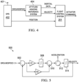
- the groundspeed data may be combined with acceleration data in a complementary filter to calculate an estimate of rotorcraft velocity.
- the acceleration data may be provided by the rotorcraft's attitude/heading reference system (AHRS), and the estimate of velocity may be calculated within the AHRS.
- AHRS attitude/heading reference system
- the estimate of the rotorcraft's velocity may be more responsive to changes. In this manner, the flight control system may be able to respond more rapidly to changes in rotorcraft velocity and thus may improve stability of the rotorcraft.
- FIG. 1 illustrates a rotorcraft 101 according to some embodiments.
- the rotorcraft 101 has a main rotor system 103, which includes a plurality of main rotor blades 105.
- the pitch of each main rotor blade 105 may be controlled by a swashplate 107 in order to selectively control the attitude, altitude and movement of the rotorcraft 101.
- the swashplate 107 may be used to collectively and/or cyclically change the pitch of the main rotor blades 105.
- the rotorcraft 101 also has an anti-torque system, which may include a tail rotor 109, no-tail-rotor (NOTAR), or dual main rotor system.
- NOTAR no-tail-rotor
- each tail rotor blade 111 is collectively changed in order to vary thrust of the anti-torque system, providing directional control of the rotorcraft 101.
- the pitch of the tail rotor blades 111 is changed by one or more tail rotor actuators.
- the FBW system sends electrical signals to the tail rotor actuators or main rotor actuators to control the flight of the rotorcraft.
- Power is supplied to the main rotor system 103 and the anti-torque system by engines 115.
- engines 115 There may be one or more engines 115, which may be controlled according to signals from the FBW system.
- the output of the engine 115 is provided to a driveshaft 117, which is mechanically and operatively coupled to the rotor system 103 and the anti-torque system through a main rotor transmission 119 and a tail rotor transmission, respectively.
- the rotorcraft 101 further includes a fuselage 125 and tail section 123.
- the tail section 123 may have other flight control devices such as horizontal or vertical stabilizers, rudder, elevators, or other control or stabilizing surfaces that are used to control or stabilize the flight of the rotorcraft 101.
- the fuselage 125 includes a cockpit 127, which includes displays, controls, and instruments. It should be appreciated that even though rotorcraft 101 is depicted as having certain illustrated features, the rotorcraft 101 may have a variety of implementation-specific configurations. For instance, in some examples, cockpit 127 is configured to accommodate a pilot or a pilot and co-pilot, as illustrated.
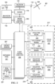
- Figure 2 illustrates a fly-by-wire flight control system 201 for a rotorcraft according to some embodiments.
- a pilot may manipulate one or more pilot flight controls in order to control the flight of the rotorcraft.
- the pilot flight controls may include manual controls such as a cyclic stick 231 in a cyclic control assembly 217, a collective stick 233 in a collective control assembly 219, and pedals 239 in a pedal assembly 221.
- Inputs provided by the pilot to the pilot flight controls may be transmitted mechanically and/or electronically (e.g., via the FBW flight control system) to flight control devices by the flight control system 201.
- Flight control devices may represent devices operable to change the flight characteristics of the rotorcraft.
- Flight control devices on the rotorcraft may include mechanical and/or electrical systems operable to change the positions or angle of attack of the main rotor blades 105 and the tail rotor blades 111 or to change the power output of the engines 115, as examples.
- Flight control devices include systems such as the swashplate 107, tail rotor actuator 113, and systems operable to control the engines 115.
- the flight control system 201 may adjust the flight control devices independently of the flight crew in order to stabilize the rotorcraft, reduce the workload of the flight crew, and the like.
- the flight control system 201 includes engine control computers (ECCUs) 203, flight control computers 205, and aircraft sensors 207, which collectively adjust the flight control devices.
- ECCUs engine control computers
- the flight control system 201 has one or more flight control computers 205 (FCCs). In some example, multiple FCCs 205 are provided for redundancy. One or more modules within the FCCs 205 may be partially or wholly embodied as software and/or hardware for performing any functionality described herein. In examples where the flight control system 201 is a FBW flight control system, the FCCs 205 may analyze pilot inputs and dispatch corresponding commands to the ECCUs 203, the tail rotor actuator 113, and/or actuators for the swashplate 107. Further, the FCCs 205 are configured and receive input commands from the pilot controls through sensors associated with each of the pilot flight controls. The input commands are received by measuring the positions of the pilot controls. The FCCs 205 also control tactile cueing commands to the pilot controls or display information in instruments on, for example, an instrument panel 241.
- the ECCUs 203 control the engines 115.
- the ECCUs 203 may vary the output power of the engines 115 to control the rotational speed of the main rotor blades or the tail rotor blades.
- the ECCUs 203 may control the output power of the engines 115 according to commands from the FCCs 205, or may do so based on feedback such a measured revolutions per minute (RPM) of the main rotor blades.
- RPM revolutions per minute
- sensors 207 could include sensors relying upon data or signals originating external to the rotorcraft, such as a global positioning system (GPS) sensor, a VHF Omnidirectional Range sensor, Instrument Landing System (ILS), and the like. It should be understood that embodiments of the present invention may be directed toward systems that utilize other satellite-based navigation systems such as the Russian global navigation satellite system (GLONASS), the Chinese BeiDou system, the European Galileo system and the Indian NAVIC system.
- GLONASS Russian global navigation satellite system
- Chinese BeiDou system the Chinese BeiDou system
- European Galileo system the European Galileo system
- Indian NAVIC system Indian NAVIC system
- the cyclic control assembly 217 is connected to a cyclic trim assembly 229 having one or more cyclic position sensors 211, one or more cyclic detent sensors 235, and one or more cyclic actuators or cyclic trim motors 209.
- the cyclic position sensors 211 measure the position of the cyclic control stick 231.
- the cyclic control stick 231 is a single control stick that moves along two axes and permits a pilot to control pitch, which is the vertical angle of the nose of the rotorcraft and roll, which is the side-to-side angle of the rotorcraft.
- the cyclic control assembly 217 has separate cyclic position sensors 211 that measuring roll and pitch separately.
- the cyclic position sensors 211 for detecting roll and pitch generate roll and pitch signals, respectively, (sometimes referred to as cyclic longitude and cyclic latitude signals, respectively) which are sent to the FCCs 205, which controls the swashplate 107, engines 115, tail rotor 109 or related flight control devices.
- the cyclic trim motors 209 are connected to the FCCs 205, and receive signals from the FCCs 205 to move the cyclic control stick 231.
- the FCCs 205 determine a suggested cyclic stick position for the cyclic stick 231 according to one or more of the collective stick position, the pedal position, the speed, altitude and attitude of the rotorcraft, the engine revolutions per minute (RPM), engine temperature, main rotor RPM, engine torque or other rotorcraft system conditions or flight conditions.
- the suggested cyclic stick position is a position determined by the FCCs 205 to give a desired cyclic action.
- the FCCs 205 send a suggested cyclic stick position signal indicating the suggested cyclic stick position to the cyclic trim motors 209. While the FCCs 205 may command the cyclic trim motors 209 to move the cyclic stick 231 to a particular position (which would in turn drive actuators associated with swashplate 107 accordingly), the cyclic position sensors 211 detect the actual position of the cyclic stick 231 that is set by the cyclic trim motors 206 or input by the pilot, allowing the pilot to override the suggested cyclic stick position.
- the collective control assembly 219 is connected to a collective trim assembly 225 having one or more collective position sensors 215, one or more collective detent sensors 237, and one or more collective actuators or collective trim motors 213.
- the collective position sensors 215 measure the position of a collective control stick 233 in the collective control assembly 219.
- the collective control stick 233 is a single control stick that moves along a single axis or with a lever type action.
- a collective position sensor 215 detects the position of the collective control stick 233 and sends a collective position signal to the FCCs 205, which controls engines 115, swashplate actuators, or related flight control devices according to the collective position signal to control the vertical movement of the rotorcraft.
- the collective trim motor 213 is connected to the FCCs 205, and receives signals from the FCCs 205 to move the collective control stick 233. Similar to the determination of the suggested cyclic stick position, in some examples, the FCCs 205 determine a suggested collective stick position for the collective control stick 233 according to one or more of the cyclic stick position, the pedal position, the speed, altitude and attitude of the rotorcraft, the engine RPM, engine temperature, main rotor RPM, engine torque or other rotorcraft system conditions or flight conditions. The FCCs 205 generate the suggested collective stick position and send a corresponding suggested collective stick signal to the collective trim motors 213 to move the collective stick 233 to a particular position.
- the collective position sensors 215 detect the actual position of the collective stick 233 that is set by the collective trim motor 213 or input by the pilot, allowing the pilot to override the suggested collective stick position.
- the cyclic and collective trim motors 209 and 213 may drive the cyclic stick 231 and collective stick 233, respectively, to suggested positions.
- the cyclic and collective trim motors 209 and 213 may drive the cyclic stick 231 and collective stick 233, respectively, to suggested positions, but this movement capability may also be used to provide tactile cueing to a pilot.
- the trim motors 209 and 213 may push the respective stick in a particular direction when the pilot is moving the stick to indicate a particular condition. Since the FBW system mechanically disconnects the stick from one or more flight control devices, a pilot may not feel a hard stop, vibration, or another tactile cue that would be inherent in a stick that is mechanically connected to a flight control assembly.
- the FCCs 205 may cause the trim motors 209 and 213 to push against a pilot command so that the pilot feels a resistive force, or may command one or more friction devices to provide friction that is felt when the pilot moves the stick.
- the FCCs 205 control the feel of a stick by providing pressure and/or friction on the stick.
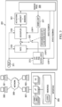
- GPS 402 may calculate a groundspeed of the rotorcraft by analyzing the carrier frequencies or the pulse widths of the received GPS signals. For example, groundspeed may be determined from measurements of the Doppler shifts of the carrier frequencies transmitted by multiple GPS satellites.
- the Doppler shift involves a change in frequency (or perceived frequency) of a waveform generated by one body and observed by a second body which is allowed to move relative to the first body.
- the Doppler shift is proportional to the relative velocities of the two bodies along the direction between the two bodies. For example, if the two bodies are moving toward each other, the frequency observed by the second body appears to be higher than the actual frequency. If the two bodies are moving apart, the frequency will appear lower.
- AHRS 404 may also provide data processing functionality and include interface circuitry between GPS 402 and flight control system 201.
- data communications between AHRS 404, GPS 402 and flight control system 201 operate according to the ARINC-429 avionics data bus standard. Alternatively, other bus standards could be used according to the particular system and its specifications.
- FIG. 6 is a flow diagram illustrating a method 600 of determining a velocity of a rotorcraft.
- a GPS signal is received by a GPS of the rotorcraft in block 602.
- the GPS signal may, for example, be a GPS carrier signal received from a GPS satellite.
- the GPS signal is processed to determine groundspeed data.
- the GPS signal is processed to determine a measured frequency of the GPS signal, and that measured frequency is compared with a reference frequency.
- Groundspeed data indicating a groundspeed of the rotorcraft is determined from a difference between the measured frequency and the reference frequency.
- the GPS signal is processed by the GPS.
- an actuator command is determined based on the velocity data.
- An FCC of the rotorcraft uses the velocity data to determine the actuator command.
- the FCC uses the velocity data to determine an actuator command in order to adjust a flight parameter of the rotorcraft.
- a flight control device is controlled according to the actuator command.
- the actuator command is sent by the FCC to one or more flight control devices to adjust flight parameters of the rotorcraft.
- the fight control devices move or change based on the actuator command to adjust the flight parameters, and resulting flight, of the rotorcraft.
- Figure 7 illustrates a computer system 701.
- the computer system 701 can be configured for performing one or more functions with regard to the operation of the flight control system 201 as described herein. Further, any processing and analysis can be partly or fully performed by the computer system 701.
- the computer system 701 can be partly or fully integrated with other aircraft computer systems or can be partly or fully removed from the rotorcraft.
- the computer system 701 may process groundspeed data and acceleration data in a complementary filter to determine an estimate of velocity, which may be similar to techniques described previously.
- the computer system 701 can include an input/output (I/O) interface 703, an analysis engine 705, and a database 707. Alternative examples can combine or distribute the I/O interface 703, the analysis engine 705, and the database 707, as desired.
- Embodiments of the computer system 701 may include one or more computers that include one or more processors and memories configured for performing tasks described herein. This can include, for example, a computer having a central processing unit (CPU) and non-volatile memory that stores software instructions for instructing the CPU to perform at least some of the tasks described herein.
- CPU central processing unit
Landscapes
- Engineering & Computer Science (AREA)
- Radar, Positioning & Navigation (AREA)
- Remote Sensing (AREA)
- Physics & Mathematics (AREA)
- General Physics & Mathematics (AREA)
- Automation & Control Theory (AREA)
- Aviation & Aerospace Engineering (AREA)
- Computer Networks & Wireless Communication (AREA)
- Mechanical Engineering (AREA)
- Control Of Position, Course, Altitude, Or Attitude Of Moving Bodies (AREA)
Claims (10)
- Procédé d'exploitation d'un giravion (101), le procédé comportant :la réception (602) d'un signal porteur de système de positionnement mondial (GPS) par un récepteur GPS (402) ;la réception (606) de données d'accélération provenant d'un capteur inertiel, le capteur inertiel comportant un système de référence d'assiette et de cap (AHRS) (404) ;le procédé étant caractérisé par :la détermination (604), par le récepteur GPS, d'une vitesse sol du giravion :en déterminant une première fréquence reçue du signal porteur de GPS ;en comparant la première fréquence reçue à une fréquence de référence pour déterminer un décalage Doppler ; eten déterminant la vitesse sol d'après le décalage Doppler ;la détermination (612), par l'AHRS, d'une vitesse d'après la vitesse sol et les données d'accélération,la détermination de la vitesse comportant le traitement de la vitesse sol et des données d'accélération à l'aide d'un filtre complémentaire (500), le filtre complémentaire (500) comportant un filtre passe-bas utilisé pour filtrer (608) les données de vitesse sol et un filtre passe-haut utilisé pour filtrer (610) les données d'accélération ;la détermination (614), par un calculateur de commandes de vol (FCC), d'une consigne d'actionneur d'après la vitesse ; etla transmission, par le FCC, de la consigne d'actionneur à un dispositif de commandes de vol du giravion pour commander un dispositif de commandes de vol selon la consigne d'actionneur.
- Procédé selon la revendication 1, le calculateur de commandes de vol (FCC) (205) étant exploitable pour recevoir une indication de la vitesse en provenance de l'AHRS (404).
- Procédé selon la revendication 1 ou la revendication 2, le traitement de la vitesse sol et des données d'accélération à l'aide d'un filtre complémentaire (500) comportant :
l'intégration des données d'accélération, et/ou la détermination la vitesse comportant en outre le traitement de données de position GPS à l'aide du filtre complémentaire (500). - Système de commandes de vol pour giravion (101), le système (201) de commandes de vol comportant :un calculateur de commandes de vol (FCC) (205) exploitable pour commander un ou plusieurs dispositifs de commandes de vol du giravion ; etun système de référence d'assiette et de cap (AHRS) (404) relié de façon à pouvoir communiquer avec le FCC, l'AHRS comportant :
un processeur et un support de stockage non transitoire lisible par ordinateur sur lequel est stocké un programme exécutable, le programme exécutable comprenant des instructions visant à :
recevoir des données de vitesse sol du giravion en provenance d'un récepteur (402) de système de positionnement mondial (GPS) ;caractérisé en ce queles données de vitesse sol sont déterminées, par le récepteur GPS, en déterminant une première fréquence reçue d'un signal porteur de GPS, en comparant la première fréquence reçue à une fréquence de référence pour déterminer un décalage Doppler ; et en déterminant la vitesse sol d'après le décalage Doppler ; et en ce que le programme exécutable comprend des instructions visant à :recevoir des données d'accélération en provenance d'un capteur inertiel de l'AHRS ;traiter les données de vitesse sol et les données d'accélération à l'aide d'un filtre complémentaire (500) pour générer des données de vitesse, le filtre complémentaire (500) comportant un filtre passe-bas utilisé pour filtrer les données de vitesse sol et un filtre passe-haut utilisé pour filtrer les données d'accélération ; ettransmettre les données de vitesse au FCC (205), le FCC (205) étant exploitable pour déterminer une consigne d'actionneur destinée à commander le ou les dispositifs de commandes de vol du giravion selon les données de vitesse et pour transmettre la consigne d'actionneur au dispositif de commandes de vol. - Système de commandes de vol selon la revendication 4, le filtre passe-bas étant un filtre passe-bas du second ordre.
- Système de commandes de vol selon l'une quelconque des revendications 4 à 5, le programme exécutable comprenant en outre des instructions visant à transmettre les données d'accélération au FCC (205), le FCC (205) étant exploitable pour commander le ou les dispositifs de commandes de vol du giravion (101) selon les données d'accélération.
- Giravion (101) comportant :un système de commandes de vol selon l'une quelconque des revendications 4 à 6 ;un récepteur (402) de système de positionnement mondial (GPS) configuré pour détecter le signal porteur de GPS et calculer des données de vitesse sol d'après le signal porteur de GPS, le récepteur GPS étant couplé au FCC et l'AHRS étant couplé au récepteur GPS système et au FCC, l'AHRS étant exploitable pour recevoir les données de vitesse sol en provenance du récepteur GPS pour calculer les données de vitesse du giravion à l'aide du filtre complémentaire (500) d'après les données de vitesse sol et les données d'accélération ; etun ou plusieurs dispositifs de commandes de vol couplés au FCC et exploitables pour commander un paramètre de vol du giravion en réponse à la consigne d'actionneur reçue en provenance du FCC ;le FCC étant exploitable pour recevoir les données de vitesse en provenance de l'AHRS, pour générer la consigne d'actionneur selon les données de vitesse, et pour envoyer la consigne d'actionneur au(x) dispositif(s) de commandes de vol.
- Giravion selon la revendication 7, la consigne d'actionneur maintenant le giravion dans un mode de vol stationnaire.
- Giravion selon la revendication 7 ou la revendication 8, la consigne d'actionneur maintenant une vitesse prédéterminée du giravion.
- Giravion selon l'une quelconque des revendications 7 à 9, le récepteur GPS étant configuré pour déterminer des données de position d'après un second signal porteur de GPS et étant configuré pour calculer les données de vitesse sol d'après le signal porteur de GPS lorsqu'il ne parvient pas à déterminer des données de position d'après le second signal porteur de GPS.
Applications Claiming Priority (1)
| Application Number | Priority Date | Filing Date | Title |
|---|---|---|---|
| US16/022,455 US10890668B2 (en) | 2018-06-28 | 2018-06-28 | System and method for determining a velocity of a rotorcraft |
Publications (2)
| Publication Number | Publication Date |
|---|---|
| EP3588231A1 EP3588231A1 (fr) | 2020-01-01 |
| EP3588231B1 true EP3588231B1 (fr) | 2023-09-20 |
Family
ID=65363054
Family Applications (1)
| Application Number | Title | Priority Date | Filing Date |
|---|---|---|---|
| EP19154943.5A Active EP3588231B1 (fr) | 2018-06-28 | 2019-01-31 | Système et procédé de détermination de la vitesse d'un giravion |
Country Status (3)
| Country | Link |
|---|---|
| US (1) | US10890668B2 (fr) |
| EP (1) | EP3588231B1 (fr) |
| CN (1) | CN110658843A (fr) |
Families Citing this family (2)
| Publication number | Priority date | Publication date | Assignee | Title |
|---|---|---|---|---|
| GB2588579A (en) * | 2019-10-09 | 2021-05-05 | Airbus Operations Ltd | Speed determination system |
| CN116149242B (zh) * | 2023-04-20 | 2023-08-04 | 北京创博联航科技有限公司 | 一种双旋翼纵列式无人机飞控系统 |
Citations (1)
| Publication number | Priority date | Publication date | Assignee | Title |
|---|---|---|---|---|
| US20070075893A1 (en) * | 2005-05-19 | 2007-04-05 | Francois Xavier Filias | System for estimating the speed of an aircraft, and an application thereof to detecting obstacles |
Family Cites Families (13)
| Publication number | Priority date | Publication date | Assignee | Title |
|---|---|---|---|---|
| US5195039A (en) * | 1990-05-03 | 1993-03-16 | United Technologies Corporation | Hover position hold system for rotary winged aircraft |
| US5535278A (en) * | 1994-05-02 | 1996-07-09 | Magnavox Electronic Systems Company | Global positioning system (GPS) receiver for recovery and tracking of signals modulated with P-code |
| US6094163A (en) * | 1998-01-21 | 2000-07-25 | Min-I James Chang | Ins alignment method using a doppler sensor and a GPS/HVINS |
| US6264146B1 (en) * | 1999-12-07 | 2001-07-24 | The Boeing Company | Portable controller for an aircraft |
| US20030135327A1 (en) * | 2002-01-11 | 2003-07-17 | Seymour Levine | Low cost inertial navigator |
| US7409290B2 (en) * | 2004-04-17 | 2008-08-05 | American Gnc Corporation | Positioning and navigation method and system thereof |
| FR2882163B1 (fr) * | 2005-02-15 | 2011-05-27 | Thales Sa | Equipement de pilotage automatique pour aeronef a voilure tournante |
| US7835863B2 (en) * | 2007-04-18 | 2010-11-16 | Mitac International Corporation | Method and system for navigation using GPS velocity vector |
| US9562788B1 (en) * | 2011-09-30 | 2017-02-07 | Rockwell Collins, Inc. | System and method for doppler aided navigation using weather radar |
| US20160221663A1 (en) * | 2014-12-18 | 2016-08-04 | Gulfstream Aerospace Corporation | Flight control computer for an aircraft that includes an inertial sensor incorporated therein |
| US10112721B2 (en) * | 2015-10-14 | 2018-10-30 | Flirtey Holdings, Inc. | Parachute deployment system for an unmanned aerial vehicle |
| CN106949889A (zh) * | 2017-03-17 | 2017-07-14 | 南京航空航天大学 | 针对行人导航的低成本mems/gps组合导航系统及方法 |
| US10846533B2 (en) * | 2017-03-27 | 2020-11-24 | Seattle Avionics, Inc. | Systems and methods for augmented reality aviation interfaces |
-
2018
- 2018-06-28 US US16/022,455 patent/US10890668B2/en active Active
-
2019
- 2019-01-17 CN CN201910047230.6A patent/CN110658843A/zh active Pending
- 2019-01-31 EP EP19154943.5A patent/EP3588231B1/fr active Active
Patent Citations (1)
| Publication number | Priority date | Publication date | Assignee | Title |
|---|---|---|---|---|
| US20070075893A1 (en) * | 2005-05-19 | 2007-04-05 | Francois Xavier Filias | System for estimating the speed of an aircraft, and an application thereof to detecting obstacles |
Non-Patent Citations (1)
| Title |
|---|
| PETOVELLO MARK: "38 InsideGNSS", GNSS SOLUTIONS, 14 March 2015 (2015-03-14), https://insidegnss.com/how-does-a-gnss-receiver-estimate-velocity/, XP055754249, Retrieved from the Internet <URL:https://insidegnss.com/wp-content/uploads/2018/01/marapr15-SOLUTIONS.pdf> [retrieved on 20201126] * |
Also Published As
| Publication number | Publication date |
|---|---|
| US10890668B2 (en) | 2021-01-12 |
| US20200003908A1 (en) | 2020-01-02 |
| CN110658843A (zh) | 2020-01-07 |
| EP3588231A1 (fr) | 2020-01-01 |
Similar Documents
| Publication | Publication Date | Title |
|---|---|---|
| EP3370129B1 (fr) | Lissage de la transition du mode de commande d'un giravion | |
| EP3357809B1 (fr) | Système et procédé de stabilisation d'une accélération longitudinale d'un giravion | |
| EP3379365B1 (fr) | Système et procédé de commande de direction de giravion | |
| EP3401751B1 (fr) | Système et procédé de filtrage actif de vibrations latérales pour giravion | |
| EP3620373A1 (fr) | Moniteurs bloqués en détente pour des manches collectives et cycliques | |
| EP3379257A1 (fr) | Données inertielles et de vitesse de l'air combinées pour la commande longitudinale d'un giravion | |
| US11312480B2 (en) | System and method for controlling rotorcraft | |
| EP3363741B1 (fr) | Système et procédé de validation de coordonnées de positionnement de giravion | |
| EP3385754B1 (fr) | Système et procédé de détermination de la position d'un giravion | |
| EP3677505B1 (fr) | Système et procédé de commande d'hélicoptère | |
| EP3599160B1 (fr) | Système et procédé de commande de vol de giravion | |
| EP3588231B1 (fr) | Système et procédé de détermination de la vitesse d'un giravion | |
| EP3677979B1 (fr) | Système et procédé de commande de giravion | |
| US10816999B2 (en) | System and method for controlling rotorcraft | |
| EP3613671B1 (fr) | Lissage de transition de mode de commande de giravion |
Legal Events
| Date | Code | Title | Description |
|---|---|---|---|
| STAA | Information on the status of an ep patent application or granted ep patent |
Free format text: STATUS: EXAMINATION IS IN PROGRESS |
|
| PUAI | Public reference made under article 153(3) epc to a published international application that has entered the european phase |
Free format text: ORIGINAL CODE: 0009012 |
|
| 17P | Request for examination filed |
Effective date: 20190131 |
|
| AK | Designated contracting states |
Kind code of ref document: A1 Designated state(s): AL AT BE BG CH CY CZ DE DK EE ES FI FR GB GR HR HU IE IS IT LI LT LU LV MC MK MT NL NO PL PT RO RS SE SI SK SM TR |
|
| AX | Request for extension of the european patent |
Extension state: BA ME |
|
| STAA | Information on the status of an ep patent application or granted ep patent |
Free format text: STATUS: EXAMINATION IS IN PROGRESS |
|
| GRAP | Despatch of communication of intention to grant a patent |
Free format text: ORIGINAL CODE: EPIDOSNIGR1 |
|
| STAA | Information on the status of an ep patent application or granted ep patent |
Free format text: STATUS: GRANT OF PATENT IS INTENDED |
|
| INTG | Intention to grant announced |
Effective date: 20210519 |
|
| RIN1 | Information on inventor provided before grant (corrected) |
Inventor name: WORSHAM III, ROBERT EARL Inventor name: COVINGTON, CHARLES ERIC Inventor name: BROOKS, THOMAS WAYNE |
|
| GRAJ | Information related to disapproval of communication of intention to grant by the applicant or resumption of examination proceedings by the epo deleted |
Free format text: ORIGINAL CODE: EPIDOSDIGR1 |
|
| STAA | Information on the status of an ep patent application or granted ep patent |
Free format text: STATUS: EXAMINATION IS IN PROGRESS |
|
| GRAP | Despatch of communication of intention to grant a patent |
Free format text: ORIGINAL CODE: EPIDOSNIGR1 |
|
| STAA | Information on the status of an ep patent application or granted ep patent |
Free format text: STATUS: GRANT OF PATENT IS INTENDED |
|
| INTC | Intention to grant announced (deleted) | ||
| INTG | Intention to grant announced |
Effective date: 20211026 |
|
| GRAJ | Information related to disapproval of communication of intention to grant by the applicant or resumption of examination proceedings by the epo deleted |
Free format text: ORIGINAL CODE: EPIDOSDIGR1 |
|
| STAA | Information on the status of an ep patent application or granted ep patent |
Free format text: STATUS: EXAMINATION IS IN PROGRESS |
|
| GRAP | Despatch of communication of intention to grant a patent |
Free format text: ORIGINAL CODE: EPIDOSNIGR1 |
|
| STAA | Information on the status of an ep patent application or granted ep patent |
Free format text: STATUS: GRANT OF PATENT IS INTENDED |
|
| INTC | Intention to grant announced (deleted) | ||
| INTG | Intention to grant announced |
Effective date: 20220707 |
|
| RIN1 | Information on inventor provided before grant (corrected) |
Inventor name: BROOKS, THOMAS WAYNE Inventor name: COVINGTON, CHARLES ERIC Inventor name: WORSHAM III, ROBERT EARL |
|
| GRAJ | Information related to disapproval of communication of intention to grant by the applicant or resumption of examination proceedings by the epo deleted |
Free format text: ORIGINAL CODE: EPIDOSDIGR1 |
|
| STAA | Information on the status of an ep patent application or granted ep patent |
Free format text: STATUS: EXAMINATION IS IN PROGRESS |
|
| INTC | Intention to grant announced (deleted) | ||
| GRAP | Despatch of communication of intention to grant a patent |
Free format text: ORIGINAL CODE: EPIDOSNIGR1 |
|
| STAA | Information on the status of an ep patent application or granted ep patent |
Free format text: STATUS: GRANT OF PATENT IS INTENDED |
|
| INTG | Intention to grant announced |
Effective date: 20230405 |
|
| GRAS | Grant fee paid |
Free format text: ORIGINAL CODE: EPIDOSNIGR3 |
|
| GRAA | (expected) grant |
Free format text: ORIGINAL CODE: 0009210 |
|
| STAA | Information on the status of an ep patent application or granted ep patent |
Free format text: STATUS: THE PATENT HAS BEEN GRANTED |
|
| P01 | Opt-out of the competence of the unified patent court (upc) registered |
Effective date: 20230807 |
|
| RAP1 | Party data changed (applicant data changed or rights of an application transferred) |
Owner name: TEXTRON INNOVATIONS INC. |
|
| AK | Designated contracting states |
Kind code of ref document: B1 Designated state(s): AL AT BE BG CH CY CZ DE DK EE ES FI FR GB GR HR HU IE IS IT LI LT LU LV MC MK MT NL NO PL PT RO RS SE SI SK SM TR |
|
| REG | Reference to a national code |
Ref country code: GB Ref legal event code: FG4D |
|
| REG | Reference to a national code |
Ref country code: CH Ref legal event code: EP |
|
| REG | Reference to a national code |
Ref country code: DE Ref legal event code: R096 Ref document number: 602019037684 Country of ref document: DE |
|
| REG | Reference to a national code |
Ref country code: IE Ref legal event code: FG4D |
|
| REG | Reference to a national code |
Ref country code: DE Ref legal event code: R079 Ref document number: 602019037684 Country of ref document: DE Free format text: PREVIOUS MAIN CLASS: G05D0001080000 Ipc: G05D0001490000 |
|
| REG | Reference to a national code |
Ref country code: LT Ref legal event code: MG9D |
|
| PG25 | Lapsed in a contracting state [announced via postgrant information from national office to epo] |
Ref country code: GR Free format text: LAPSE BECAUSE OF FAILURE TO SUBMIT A TRANSLATION OF THE DESCRIPTION OR TO PAY THE FEE WITHIN THE PRESCRIBED TIME-LIMIT Effective date: 20231221 |
|
| REG | Reference to a national code |
Ref country code: NL Ref legal event code: MP Effective date: 20230920 |
|
| PG25 | Lapsed in a contracting state [announced via postgrant information from national office to epo] |
Ref country code: SE Free format text: LAPSE BECAUSE OF FAILURE TO SUBMIT A TRANSLATION OF THE DESCRIPTION OR TO PAY THE FEE WITHIN THE PRESCRIBED TIME-LIMIT Effective date: 20230920 Ref country code: RS Free format text: LAPSE BECAUSE OF FAILURE TO SUBMIT A TRANSLATION OF THE DESCRIPTION OR TO PAY THE FEE WITHIN THE PRESCRIBED TIME-LIMIT Effective date: 20230920 Ref country code: NO Free format text: LAPSE BECAUSE OF FAILURE TO SUBMIT A TRANSLATION OF THE DESCRIPTION OR TO PAY THE FEE WITHIN THE PRESCRIBED TIME-LIMIT Effective date: 20231220 Ref country code: LV Free format text: LAPSE BECAUSE OF FAILURE TO SUBMIT A TRANSLATION OF THE DESCRIPTION OR TO PAY THE FEE WITHIN THE PRESCRIBED TIME-LIMIT Effective date: 20230920 Ref country code: LT Free format text: LAPSE BECAUSE OF FAILURE TO SUBMIT A TRANSLATION OF THE DESCRIPTION OR TO PAY THE FEE WITHIN THE PRESCRIBED TIME-LIMIT Effective date: 20230920 Ref country code: HR Free format text: LAPSE BECAUSE OF FAILURE TO SUBMIT A TRANSLATION OF THE DESCRIPTION OR TO PAY THE FEE WITHIN THE PRESCRIBED TIME-LIMIT Effective date: 20230920 Ref country code: GR Free format text: LAPSE BECAUSE OF FAILURE TO SUBMIT A TRANSLATION OF THE DESCRIPTION OR TO PAY THE FEE WITHIN THE PRESCRIBED TIME-LIMIT Effective date: 20231221 Ref country code: FI Free format text: LAPSE BECAUSE OF FAILURE TO SUBMIT A TRANSLATION OF THE DESCRIPTION OR TO PAY THE FEE WITHIN THE PRESCRIBED TIME-LIMIT Effective date: 20230920 |
|
| REG | Reference to a national code |
Ref country code: AT Ref legal event code: MK05 Ref document number: 1613886 Country of ref document: AT Kind code of ref document: T Effective date: 20230920 |
|
| PG25 | Lapsed in a contracting state [announced via postgrant information from national office to epo] |
Ref country code: NL Free format text: LAPSE BECAUSE OF FAILURE TO SUBMIT A TRANSLATION OF THE DESCRIPTION OR TO PAY THE FEE WITHIN THE PRESCRIBED TIME-LIMIT Effective date: 20230920 |
|
| PG25 | Lapsed in a contracting state [announced via postgrant information from national office to epo] |
Ref country code: IS Free format text: LAPSE BECAUSE OF FAILURE TO SUBMIT A TRANSLATION OF THE DESCRIPTION OR TO PAY THE FEE WITHIN THE PRESCRIBED TIME-LIMIT Effective date: 20240120 |
|
| PG25 | Lapsed in a contracting state [announced via postgrant information from national office to epo] |
Ref country code: AT Free format text: LAPSE BECAUSE OF FAILURE TO SUBMIT A TRANSLATION OF THE DESCRIPTION OR TO PAY THE FEE WITHIN THE PRESCRIBED TIME-LIMIT Effective date: 20230920 |
|
| PG25 | Lapsed in a contracting state [announced via postgrant information from national office to epo] |
Ref country code: ES Free format text: LAPSE BECAUSE OF FAILURE TO SUBMIT A TRANSLATION OF THE DESCRIPTION OR TO PAY THE FEE WITHIN THE PRESCRIBED TIME-LIMIT Effective date: 20230920 |
|
| PG25 | Lapsed in a contracting state [announced via postgrant information from national office to epo] |
Ref country code: SM Free format text: LAPSE BECAUSE OF FAILURE TO SUBMIT A TRANSLATION OF THE DESCRIPTION OR TO PAY THE FEE WITHIN THE PRESCRIBED TIME-LIMIT Effective date: 20230920 Ref country code: RO Free format text: LAPSE BECAUSE OF FAILURE TO SUBMIT A TRANSLATION OF THE DESCRIPTION OR TO PAY THE FEE WITHIN THE PRESCRIBED TIME-LIMIT Effective date: 20230920 Ref country code: IS Free format text: LAPSE BECAUSE OF FAILURE TO SUBMIT A TRANSLATION OF THE DESCRIPTION OR TO PAY THE FEE WITHIN THE PRESCRIBED TIME-LIMIT Effective date: 20240120 Ref country code: ES Free format text: LAPSE BECAUSE OF FAILURE TO SUBMIT A TRANSLATION OF THE DESCRIPTION OR TO PAY THE FEE WITHIN THE PRESCRIBED TIME-LIMIT Effective date: 20230920 Ref country code: EE Free format text: LAPSE BECAUSE OF FAILURE TO SUBMIT A TRANSLATION OF THE DESCRIPTION OR TO PAY THE FEE WITHIN THE PRESCRIBED TIME-LIMIT Effective date: 20230920 Ref country code: CZ Free format text: LAPSE BECAUSE OF FAILURE TO SUBMIT A TRANSLATION OF THE DESCRIPTION OR TO PAY THE FEE WITHIN THE PRESCRIBED TIME-LIMIT Effective date: 20230920 Ref country code: AT Free format text: LAPSE BECAUSE OF FAILURE TO SUBMIT A TRANSLATION OF THE DESCRIPTION OR TO PAY THE FEE WITHIN THE PRESCRIBED TIME-LIMIT Effective date: 20230920 Ref country code: SK Free format text: LAPSE BECAUSE OF FAILURE TO SUBMIT A TRANSLATION OF THE DESCRIPTION OR TO PAY THE FEE WITHIN THE PRESCRIBED TIME-LIMIT Effective date: 20230920 Ref country code: PT Free format text: LAPSE BECAUSE OF FAILURE TO SUBMIT A TRANSLATION OF THE DESCRIPTION OR TO PAY THE FEE WITHIN THE PRESCRIBED TIME-LIMIT Effective date: 20240122 |
|
| PGFP | Annual fee paid to national office [announced via postgrant information from national office to epo] |
Ref country code: DE Payment date: 20240129 Year of fee payment: 6 Ref country code: GB Payment date: 20240129 Year of fee payment: 6 |
|
| PG25 | Lapsed in a contracting state [announced via postgrant information from national office to epo] |
Ref country code: PL Free format text: LAPSE BECAUSE OF FAILURE TO SUBMIT A TRANSLATION OF THE DESCRIPTION OR TO PAY THE FEE WITHIN THE PRESCRIBED TIME-LIMIT Effective date: 20230920 Ref country code: IT Free format text: LAPSE BECAUSE OF FAILURE TO SUBMIT A TRANSLATION OF THE DESCRIPTION OR TO PAY THE FEE WITHIN THE PRESCRIBED TIME-LIMIT Effective date: 20230920 |
|
| PGFP | Annual fee paid to national office [announced via postgrant information from national office to epo] |
Ref country code: FR Payment date: 20240125 Year of fee payment: 6 |
|
| REG | Reference to a national code |
Ref country code: DE Ref legal event code: R097 Ref document number: 602019037684 Country of ref document: DE |
|
| PG25 | Lapsed in a contracting state [announced via postgrant information from national office to epo] |
Ref country code: DK Free format text: LAPSE BECAUSE OF FAILURE TO SUBMIT A TRANSLATION OF THE DESCRIPTION OR TO PAY THE FEE WITHIN THE PRESCRIBED TIME-LIMIT Effective date: 20230920 |
|
| PLBE | No opposition filed within time limit |
Free format text: ORIGINAL CODE: 0009261 |
|
| STAA | Information on the status of an ep patent application or granted ep patent |
Free format text: STATUS: NO OPPOSITION FILED WITHIN TIME LIMIT |
|
| PG25 | Lapsed in a contracting state [announced via postgrant information from national office to epo] |
Ref country code: DK Free format text: LAPSE BECAUSE OF FAILURE TO SUBMIT A TRANSLATION OF THE DESCRIPTION OR TO PAY THE FEE WITHIN THE PRESCRIBED TIME-LIMIT Effective date: 20230920 |
|
| PG25 | Lapsed in a contracting state [announced via postgrant information from national office to epo] |
Ref country code: MC Free format text: LAPSE BECAUSE OF FAILURE TO SUBMIT A TRANSLATION OF THE DESCRIPTION OR TO PAY THE FEE WITHIN THE PRESCRIBED TIME-LIMIT Effective date: 20230920 |
|
| 26N | No opposition filed |
Effective date: 20240621 |
|
| PG25 | Lapsed in a contracting state [announced via postgrant information from national office to epo] |
Ref country code: MC Free format text: LAPSE BECAUSE OF FAILURE TO SUBMIT A TRANSLATION OF THE DESCRIPTION OR TO PAY THE FEE WITHIN THE PRESCRIBED TIME-LIMIT Effective date: 20230920 |
|
| REG | Reference to a national code |
Ref country code: CH Ref legal event code: PL |
|
| PG25 | Lapsed in a contracting state [announced via postgrant information from national office to epo] |
Ref country code: LU Free format text: LAPSE BECAUSE OF NON-PAYMENT OF DUE FEES Effective date: 20240131 |