EP3588130A1 - Optischer sensor - Google Patents
Optischer sensor Download PDFInfo
- Publication number
- EP3588130A1 EP3588130A1 EP19166029.9A EP19166029A EP3588130A1 EP 3588130 A1 EP3588130 A1 EP 3588130A1 EP 19166029 A EP19166029 A EP 19166029A EP 3588130 A1 EP3588130 A1 EP 3588130A1
- Authority
- EP
- European Patent Office
- Prior art keywords
- optical sensor
- receiving elements
- camera
- partial area
- control command
- Prior art date
- Legal status (The legal status is an assumption and is not a legal conclusion. Google has not performed a legal analysis and makes no representation as to the accuracy of the status listed.)
- Granted
Links
Images

Classifications
-
- G—PHYSICS
- G01—MEASURING; TESTING
- G01S—RADIO DIRECTION-FINDING; RADIO NAVIGATION; DETERMINING DISTANCE OR VELOCITY BY USE OF RADIO WAVES; LOCATING OR PRESENCE-DETECTING BY USE OF THE REFLECTION OR RERADIATION OF RADIO WAVES; ANALOGOUS ARRANGEMENTS USING OTHER WAVES
- G01S7/00—Details of systems according to groups G01S13/00, G01S15/00, G01S17/00
- G01S7/48—Details of systems according to groups G01S13/00, G01S15/00, G01S17/00 of systems according to group G01S17/00
-
- G—PHYSICS
- G01—MEASURING; TESTING
- G01S—RADIO DIRECTION-FINDING; RADIO NAVIGATION; DETERMINING DISTANCE OR VELOCITY BY USE OF RADIO WAVES; LOCATING OR PRESENCE-DETECTING BY USE OF THE REFLECTION OR RERADIATION OF RADIO WAVES; ANALOGOUS ARRANGEMENTS USING OTHER WAVES
- G01S17/00—Systems using the reflection or reradiation of electromagnetic waves other than radio waves, e.g. lidar systems
- G01S17/86—Combinations of lidar systems with systems other than lidar, radar or sonar, e.g. with direction finders
Definitions
- the invention relates to an optical sensor.
- Such optical sensors have a camera with an arrangement of reception elements and an evaluation unit for evaluating reception signals of the reception elements of the camera.
- the optical sensor typically also has an illumination device.
- the camera is usually formed by a CMOS or CCD array, which has a matrix-like arrangement of receiving elements.
- optical sensors can be designed as code reading devices in order to detect codes, in particular bar codes.
- a problem with such optical sensors is the detection of fast moving objects. If the objects quickly dive into the detection range of the camera of the optical sensor, the internal triggering of the camera is not fast enough to still be able to detect the object.
- a limiting error here is, in particular, the relatively long time that is required to read the received signals from all of the receiving elements from the camera.
- a known approach to solving this problem is to use additional sensors, such as light barriers, in addition to the optical sensor, whose signals are used to trigger the camera.
- additional sensors such as light barriers
- the invention has for its object to provide an optical sensor which has a high functionality with little design effort.
- the invention relates to an optical sensor with a camera having a number of receiving elements and with an evaluation unit, which is designed to evaluate received signals from receiving elements of the camera.
- Control means are provided, by means of which at least a partial area of the receiving elements can be selected.
- the camera is designed in such a way that only the reception signals of the reception elements of the selected partial area are read out and then fed to the evaluation unit.
- a control command for setting the operation of the optical sensor can be generated in the evaluation unit depending on the received signals of the received elements of the selected partial area.
- An essential aspect of the invention is that the camera is configured with the control means in such a way that only a selected partial area of the receiving elements is read out by the camera.
- the position and size of the selected partial area can be freely specified with the control means.
- a sensor function can thus be specifically implemented with the camera configured in this way, which can in particular replace an external sensor system.
- the selected partial area corresponding to an ROI comprises only a part of the reception elements, which advantageously comprises only a small part of all reception elements and, in the limit case, even only a single reception element, the reception signals of the reception elements can be read out of the selected sub-area take place quickly, so that a correspondingly short response time is obtained for evaluating the received signals of the selected sub-area.
- a control command for setting the operation of the optical sensor is generated depending on the evaluation of the received signals of the received elements of the selected partial area.
- An internal sensor function is provided with the arrangement of the received signals of the received elements of the selected partial area, with which the operation of the optical sensor can be set with short reaction times.
- the image recording of the optical sensor can be triggered quickly and without the use of external sensors.
- a target object can be detected particularly advantageously by evaluating the received signals of the received elements of the selected partial area.
- the target object and the selected partial area of the receiving elements which is preferably adapted to this, thus form a sensor arrangement, the sensor signals of which are used to control the operating mode of the optical sensor. Since the receiving elements of the camera and also the evaluation unit of the optical sensor can also be used here, there is no need for corresponding separate units for forming this sensor function.
- the target object can in particular be designed in the form of a reflector such as a retroreflector.
- the optical sensor with the assigned reflector forms a reflection light barrier, with which the penetration of an object between the reflector and the optical sensor can be detected quickly. Operation is then set depending on whether an object has been detected with this retro-reflective sensor or not.
- a corresponding sensor function can be implemented in that a light source such as one or more light-emitting diodes, can be provided, the light of which is emitted in the direction of the selected partial area of the receiving elements of the camera.
- a light source such as one or more light-emitting diodes
- the target object can be formed by a code that is detected with the receiving elements of the selected partial area, the operation of the optical sensor then being set depending on the code information contained in the code.
- amplitude movements of the received signals of the received elements of the selected partial area are carried out to detect the target object.
- the contrast structures of the code can be detected with the amplitude evaluation and the code information contained in the contrast structures can thus be decoded.
- this target object can be detected by a threshold value evaluation of the amplitudes of the received signals of the received elements of the selected partial area.
- the threshold value setting is advantageously carried out adaptively.
- two selected sub-areas can be defined, with only a selected sub-area being aligned with the target object.
- the threshold value for the received signals of the received elements of the first selected partial area can be adjusted adaptively.
- distance measurements are carried out to detect the target object on the basis of the received signals of the receiving elements of the selected partial area.
- the camera is assigned at least one transmitter light source that emits light beams.
- the transit time of the light rays is then recorded for distance measurement when they are directed onto an object and are reflected back from there to the camera.
- Distance measurements can advantageously be carried out individually for all receiving elements.
- target objects in the form of objects with defined geometries can be used.
- the detection of target objects such as codes, light sources or reflectors can be differentiated and specified more precisely.
- objects are identified with codes, they can be classified not only on the basis of the code information but also on the basis of their distances from the optical sensor and then set the operation of the optical sensor as a function of the detection of certain codes.
- a plurality of selected partial areas is provided, the received signals of the receiving elements of all selected partial areas being able to be read out simultaneously.
- a specific target object can be recognized with each selected partial area.
- a structurally simple example consists of a reflector strip, which is covered with a template having a number of holes. Individual reflector fields are then visible through the holes and can be detected with the respective selected partial areas. By capturing The operation of the optical sensor can then be set specifically for individual or multiple target objects and / or by means of a specific sequence of recognizing target objects in the individually selected partial areas.
- templates can also be specified using the software of the optical sensor.
- a time-variable specification of selected partial areas is provided.
- selected sub-areas are specified by parameterization.
- the parameterization can be carried out by learning processes or by external units such as Internet interfaces.
- the operating mode can be set by the control command.
- control command can thus be used to select a specific operating mode.
- the optical sensor can be operated as a code reading device by a control command.
- an image recording can be enabled with the control command.
- the control command thus triggers the image acquisition with the optical sensor, so that even fast-moving objects can be detected reliably.
- Different selected partial areas or all of the camera receiving elements are activated for the image acquisition by the control command.
- this can be parameterized using the control command.
- parameters of the optical sensor for image acquisition can be set, such as the size of the detection area, definition of different ROI or parameters for the evaluation of the received signals of the receiving elements.
- Communication with an external unit is also controlled by the control command.
- the type of output signals to an external unit can be specified.
- different interface parameters for outputting the output signals can be specified via different interfaces such as lines, bus systems and the like.
- an actuator coupled to the optical sensor is controlled by means of the control commands.
- the directions or speeds of target objects can be determined by evaluating these partial areas, wherein actuators can be controlled as a function of such measured variables.
- control means are formed by program modules assigned to the camera.
- the camera with the program module integrated in a sensor control then forms a compact structural unit that can be used without further components for specifying specific ROI.
- the camera particularly advantageously has a matrix-like arrangement of receiving elements.
- the camera designed in this way has a large number of receiving elements, so that a high image resolution can be achieved.
- the camera has a CMOS or CCD array.
- the optical sensor has an illumination device.
- the illumination device illuminates the area that can be detected by the optical sensor, which improves the object detection. If the optical sensor is used for distance measurement, the lighting device emits the light beams, the run times of which are used to determine the distance from objects. In particular, in the event that target objects themselves form light sources, the lighting device can be dispensed with.
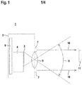
- Figure 1 shows schematically an embodiment of the optical sensor 1 according to the invention.
- the components of the optical sensor are integrated in a housing 2.
- the optical sensor has a camera 7, which is controlled by a sensor controller 4.
- An optical receiving system 5 is assigned to the camera 3. Object detection is made possible with the camera 3 within an image field 6.
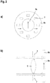
- the optical sensor has a lighting device which is formed from a number of individual light sources 7 which are arranged coaxially with the camera 3 ( Figures 2a, b ).
- the receiving optics 5 are preceded by first polarization means 8a and second polarization means 8b are arranged downstream of the individual light sources 7.
- the polarization directions of the polarization means 8a, 8b are oriented perpendicular to one another, as with the arrows in FIG Figure 2a illustrated.
- the optical sensor also has an evaluation unit 9, which can be formed by a microprocessor or the like.
- the evaluation unit 9 evaluates reception signals from the camera 3 for object detection. Furthermore, the evaluation unit 9 serves to control the lighting device. Finally, the sensor controller 4 can be controlled by the evaluation unit 9. Alternatively or additionally, the sensor signals can be controlled by control signals from an external control, not shown. In particular, cloud-based systems are also possible.
- Light beams 10 are emitted from the individual light sources 7 and are used to illuminate the image field 6 of the camera 3. Here are in Figure 1 only the beam axes of these light beams 10 are shown.
- the light beams 10 can also be used for a distance measurement by determining the transit time of the light beams 10, preferably in the form of light pulses, to an object.
- the optical sensor then forms a distance image camera.
- Figure 3 shows a plan view of the light-sensitive surface 7a of the camera 3, which consists of a matrix-shaped arrangement of receiving elements 12. In principle, a line-shaped arrangement of receiving elements 12 is also possible. Receiving signals are generated from each receiving element 12 and can be evaluated in the evaluation unit 9.
- the camera 3 can be formed by a CCD or CMOS array.
- control commands generated in the evaluation unit 9 or control commands entered by the controller can be used, for example, to control a program module in the sensor controller 4, which forms a control means such that not all of the receiving elements 12 of the camera 3 are read out, but rather only one or more selected sub-areas 13, which comprise only a preferably very small part of the receiving elements 12 of the camera 3.
- the receiving elements 12 can be addressed exactly, so that only these receiving elements 12 of the selected partial area 13 are read out.
- the columns of the receiving elements 12 can be selected of the selected partial area 13 can be read out, as in Figure 3 illustrated.
- only the rows of the receiving elements 12 of the selected partial area 13 can be read out.
- the read-out lines can be considerably shortened in comparison with a complete reading out of all the receiving elements 12 of the camera 3. Furthermore, the frequency of the readout processes can be increased.
- the operation of the optical sensor is set as a function of the received signals of the selected partial area 13.
- the selected partial area 13 (as in Figure 3 illustrated) is preferably dimensioned such that a defined target object is captured with it.
- Such a target object is, for example, the reflector 11 according to FIG Figure 1 .
- the target object can be formed by a light source, which for example consists of one or more light diodes.
- the target object can be formed by a code applied to an object, which can be detected and decoded with the optical sensors.
- the evaluation unit 9 advantageously carries out an amplitude evaluation, in particular a threshold value evaluation, of the reception signals of the reception elements 12 of the selected partial area 13. Alternatively or additionally, distance measurements can be carried out.
- a threshold value evaluation of the amplitudes of the received signals can be used to determine whether or not an object intervention has occurred in the area between the reflector 11 and the optical sensor 1. If an object is recognized, the evaluation unit 9 generates a control command with which the operating mode of the optical sensor is set. For example, this triggers the image recording of the camera 3 so that it can then capture the penetrating object with preferably all of the receiving elements 12. Alternatively, only individual selected partial areas 13 of the receiving elements 12 can be read out again during the image recording.
- the operating mode of the optical sensor can be represented by the control command, for example the optical sensor can be operated as a code reading device.
- optical sensor can be parameterized using the control command.
- communication with an external unit can be controlled by the control command.
- an actuator coupled to the optical sensor can be controlled by means of the control command.
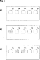
- FIGS. 4a - c show an embodiment in which a plurality of target objects are provided in the form of a plurality of reflectors 11a-e which are arranged along a straight line.
- This arrangement can be formed, for example, by placing a template with five holes on a reflector strip.
- a suitable selected partial area 13 is detected for each reflector 11a-e on the light-sensitive surface 7a of the camera 3.
- the five selected partial areas 13 are selectively and simultaneously read out of the camera 3 and fed to the evaluation unit 9.
- Figure 4a shows the situation when there is no object between the reflectors 11a-e and the optical sensor. Then all reflectors 11a-e are recognized by the optical sensor.
- Figure 4b shows the situation when an object enters the area delimited by the reflectors 11a-e. Accordingly, the light path is through the object interrupted to the reflector 11a, but not to the other reflectors 11b-e.
- Figure 4c shows the situation when the object has completely penetrated into the area delimited by the reflectors 11a-e.
- the light paths to the reflectors 11b, 11c are interrupted by the object, but not to the other reflectors 11a, 11d, 11e.
- the positions, speeds and sizes of objects can thus be detected by the time and location-resolved detection of object interventions with the reflectors 11a-11e.
- the control commands for setting the operation of the optical sensor can be generated.
Landscapes
- Engineering & Computer Science (AREA)
- Radar, Positioning & Navigation (AREA)
- Remote Sensing (AREA)
- Physics & Mathematics (AREA)
- Computer Networks & Wireless Communication (AREA)
- General Physics & Mathematics (AREA)
- Electromagnetism (AREA)
- Geophysics And Detection Of Objects (AREA)
- Studio Devices (AREA)
- Length Measuring Devices By Optical Means (AREA)
Abstract
Description
- Die Erfindung betrifft einen optischen Sensor.
- Derartige optische Sensoren weisen eine Kamera mit einer Anordnung von Empfangselementen sowie eine Auswerteeinheit zur Auswertung von Empfangssignalen der Empfangselemente der Kamera auf. Typischerweise weist der optische Sensor auch eine Beleuchtungseinrichtung auf. Die Kamera ist üblicherweise von einem CMOS- oder CCD-Array gebildet, welches eine matrixförmige Anordnung von Empfangselementen aufweist.
- Mit derartigen optischen Sensoren können Objekterfassungen unterschiedlicher Art durchgeführt werden. Insbesondere können die optischen Sensoren als Codelesegeräte ausgebildet sein um Codes, insbesondere Barcodes, zu erfassen.
- Ein Problem bei derartigen optischen Sensoren ist die Erfassung schnell bewegter Objekte. Tauchen die Objekte schnell in den Erfassungsbereich der Kamera des optischen Sensors ein, ist die interne Triggerung der Kamera nicht schnell genug um das Objekt noch erfassen zu können. Ein begrenzender Fehler hierbei ist insbesondere auch die relativ große Zeit, die benötigt wird um die Empfangssignale aller Empfangselemente aus der Kamera auszulesen.
- Ein bekannter Ansatz zur Lösung dieses Problems besteht darin, zusätzlich zum optischen Sensor weitere Sensoren wie Lichtschranken einzusetzen, deren Signale zur Triggerung der Kamera verwendet werden. Nachteilig hierbei ist, dass derartige weitere Sensoren einen erheblichen Aufwand bedeuten.
- Der Erfindung liegt die Aufgabe zugrunde einen optischen Sensor bereitzustellen, welcher bei geringem konstruktivem Aufwand eine hohe Funktionalität aufweist.
- Zur Lösung dieser Aufgabe sind die Merkmale des Anspruchs 1 vorgesehen. Vorteilhafte Ausführungsformen und zweckmäßige Weiterbildungen der Erfindung sind in den abhängigen Ansprüchen beschrieben.
- Die Erfindung betrifft einen optischen Sensor mit einer eine Anzahl von Empfangselementen aufweisenden Kamera und mit einer Auswerteeinheit, welche ausgebildet ist Empfangssignale von Empfangselementen der Kamera auszuwerten. Es sind dabei Steuermittel vorgesehen, mittels derer wenigstens ein Teilbereich der Empfangselemente auswählbar ist. Die Kamera ist derart ausgebildet, dass nur die Empfangssignale der Empfangselemente des ausgewählten Teilbereichs ausgelesen werden und dann der Auswerteeinheit zugeführt werden. In der Auswerteeinheit ist in Abhängigkeit der Empfangssignale der Empfangselemente des ausgewählten Teilbereichs ein Steuerbefehl zur Einstellung des Betriebs des optischen Sensors generierbar.
- Ein wesentlicher Aspekt der Erfindung besteht darin, dass mit den Steuermitteln die Kamera derart konfiguriert wird, dass nur ein ausgewählter Teilbereich der Empfangselemente von der Kamera ausgelesen wird. Mit den Steuermitteln kann dabei die Position und Größe des ausgewählten Teilbereichs frei vorgegeben werden. Damit kann gezielt mit der so konfigurierten Kamera eine Sensorfunktion realisiert werden, die insbesondere eine externe Sensorik ersetzen kann.
- Da der einem ROI (region of interest) entsprechende ausgewählte Teilbereich nur einen Teil der Empfangselemente umfasst, der vorteilhaft nur einen kleinen Teil aller Empfangselemente und im Grenzfall sogar nur ein einziges Empfangselement umfasst, kann das Auslesen der Empfangssignale der Empfangselemente des ausgewählten Teilbereichs schnell erfolgen, so dass eine entsprechend kurze Reaktionszeit für die Auswertung der Empfangssignale des ausgewählten Teilbereichs erhalten wird.
- Erfindungsgemäß wird abhängig von der Auswertung der Empfangssignale der Empfangselemente des ausgewählten Teilbereichs ein Steuerbefehl zur Einstellung des Betriebs des optischen Sensors generiert. Mit der Anordnung der Empfangssignale der Empfangselemente des ausgewählten Teilbereichs wird eine interne Sensorfunktion bereitgestellt, mit der mit kurzen Reaktionszeiten der Betrieb des optischen Sensors eingestellt werden kann. Insbesondere kann damit die Bildaufnahme des optischen Sensors schnell und ohne Einsatz externer Sensoren getriggert werden.
- Besonders vorteilhaft ist durch Auswertung der Empfangssignale der Empfangselemente des ausgewählten Teilbereichs ein Zielobjekt erfassbar.
- Das Zielobjekt und der vorzugsweise an dieses angepasste ausgewählte Teilbereich der Empfangselemente bilden somit eine Sensoranordnung, deren Sensorsignale zur Steuerung der Betriebsart des optischen Sensors verwendet werden. Da die Empfangselemente der Kamera und auch die Auswerteeinheit des optischen Sensors hierbei mitgenutzt werden können, entfallen entsprechende separate Einheiten zur Ausbildung dieser Sensorfunktion.
- Das Zielobjekt kann insbesondere in Form eines Reflektors wie zum Beispiel eines Retroreflektors ausgebildet sein. In diesem Fall bildet der optische Sensor mit dem zugeordneten Reflektor eine Reflexionslichtschranke, mit der ein Eindringen eines Objekts zwischen Reflektor und optischem Sensor schnell erfasst werden kann. Die Einstellung des Betriebs erfolgt dann abhängig davon ob mit dieser Reflexionslichtschranke ein Objekt erkannt wurde oder nicht.
- Eine entsprechende Sensorfunktion kann dadurch realisiert werden, dass als Zielobjekt eine Lichtquelle wie zum Beispiel eine oder mehrere Leuchtdioden, vorgesehen werden, deren Licht in Richtung des ausgewählten Teilbereichs der Empfangselemente der Kamera emittiert wird.
- Schließlich kann das Zielobjekt von einem Code gebildet sein, der mit den Empfangselementen des ausgewählten Teilbereichs erfasst wird, wobei dann abhängig von der im Code enthaltenen Codeinformation der Betrieb des optischen Sensors eingestellt wird.
- Gemäß einer vorteilhaften Ausgestaltung werden zur Erfassung des Zielobjekts Amplitudenbewegungen der Empfangssignale der Empfangselemente des ausgewählten Teilbereichs durchgeführt.
- Bei einer Ausbildung des Zielobjekts in Form eines Codes können mit der Amplitudenbewertung die Kontraststrukturen des Codes erfasst und so die in den Kontraststrukturen enthaltenen Codeinformationen dekodiert werden.
- Bei einer Ausbildung des Zielobjekts in Form eines Reflektors oder einer Lichtquelle kann dieses Zielobjekt durch eine Schwellwertbewertung der Amplituden der Empfangssignale der Empfangselemente des ausgewählten Teilbereichs erfasst werden.
- Vorteilhaft erfolgt die Schwellwerteinstellung adaptiv. Hierzu können beispielsweise zwei ausgewählte Teilbereiche definiert sein, wobei nur ein ausgewählter Teilbereich auf das Zielobjekt ausgerichtet ist. Mit der Referenzierung der Empfangssignale der Empfangselemente dieses ausgewählten Teilbereichs auf die Empfangssignale der Empfangselemente des zweiten ausgewählten Teilbereichs, die nicht auf das Zielobjekt ausgerichtet sind, kann der Schwellwert für die Empfangssignale der Empfangselemente des ersten ausgewählten Teilbereichs adaptiv eingestellt werden.
- Alternativ oder zusätzlich werden zur Erfassung des Zielobjekts anhand der Empfangssignale der Empfangselemente des ausgewählten Teilbereichs Distanzmessungen durchgeführt.
- In diesem Fall ist der Kamera wenigstens eine Senderlichtquelle zugeordnet, die Lichtstrahlen emittiert. Zur Distanzmessung wird dann die Laufzeit der Lichtstrahlen erfasst, wenn diese auf ein Objekt geführt sind und von dort zur Kamera zurückreflektiert sind. Vorteilhaft können für alle Empfangselemente einzeln Distanzmessungen durchgeführt werden.
- Mit der Durchführung derartiger Distanzmessungen können Zielobjekte in Form von Objekten mit definierten Geometrien eingesetzt werden.
- Weiterhin kann beispielsweise die Erkennung von Zielobjekten wie Codes, Lichtquellen oder Reflektoren genauer differenziert und spezifiziert werden.
- Werden beispielsweise Objekte mit Codes gekennzeichnet, so können diese nicht nur anhand der Codeinformationen sondern anhand deren Abstände zum optischen Sensor klassifiziert werden und dann in Abhängigkeit der Erkennung bestimmter Codes den Betrieb des optischen Sensors einstellen.
- Gemäß einer vorteilhaften Weiterbildung ist eine Mehrzahl von ausgewählten Teilbereichen vorgesehen, wobei die Empfangssignale der Empfangselemente aller ausgewählten Teilbereiche simultan auslesbar sind.
- Beispielsweise kann mit jedem ausgewählten Teilbereich ein spezifisches Zielobjekt erkannt werden. Ein konstruktiv einfaches Beispiel besteht in einer Reflektorleiste, die mit einer eine Anzahl von Löchern aufweisenden Schablone abgedeckt wird. Durch die Löcher sind dann einzelne Reflektorfelder sichtbar, die mit den jeweiligen ausgewählten Teilbereichen erfassbar sind. Durch Erfassung einzelner oder mehrerer Zielobjekte und /oder durch eine bestimmte Abfolge der Erkennung von Zielobjekten in den einzelnen ausgewählten Teilbereichen kann dann der Betrieb des optischen Sensors spezifisch eingestellt werden.
- Generell können derartige Schablonen auch über die Software des optischen Sensors vorgegeben werden.
- Gemäß einer vorteilhaften Ausführungsform ist eine zeitlich veränderbare Vorgabe von ausgewählten Teilbereichen vorgesehen.
- Dabei erfolgt die Vorgabe von ausgewählten Teilbereichen durch eine Parametrierung.
- Die Parametrierung kann durch Einlernvorgänge oder durch externe Einheiten wie Internet-Oberflächen durchgeführt werden.
- Gemäß einer vorteilhaften Ausgestaltung ist durch den Steuerbefehl dessen Betriebsart einstellbar.
- Wenn der optische Sensor in unterschiedlichen Betriebsarten betrieben werden kann, kann somit durch den Steuerbefehl eine bestimmte Betriebsart ausgewählt werden.
- Beispielsweise kann der optische Sensor durch einen Steuerbefehl als Codelesegerät betrieben werden.
- Gemäß einer weiteren vorteilhaften Ausgestaltung ist mit dem Steuerbefehl eine Bildaufnahme freigebbar.
- Mit dem Steuerbefehl erfolgt somit eine Triggerung der Bildaufnahme mit dem optischen Sensor, so dass mit diesem auch schnell bewegte Objekte sicher erfasst werden können.
- Dabei sind durch den Steuerbefehl unterschiedliche ausgewählte Teilbereiche oder alle Empfangselemente der Kamera für die Bildaufnahme aktiviert.
- Gemäß einer weiteren vorteilhaften Ausführungsform ist dieser durch den Steuerbefehl parametrierbar.
- Mit der Parametrierung können Kenngrößen des optischen Sensors zur Bildaufnahme eingestellt werden, wie die Größe des Erfassungsbereichs, Definition unterschiedlicher ROI oder Parameter für die Auswertung der Empfangssignale der Empfangselemente.
- Weiterhin ist durch den Steuerbefehl die Kommunikation mit einer externen Einheit gesteuert.
- Beispielsweise kann damit die Art der Ausgabesignale an eine externe Einheit vorgegeben werden. Weiterhin können unterschiedliche Schnittstellenparameter zur Ausgabe der Ausgangssignale über unterschiedliche Schnittstellen wie Leitungen, Bussysteme und dergleichen vorgegeben werden.
- Schließlich ist mittels der Steuerbefehle ein mit dem optischen Sensor gekoppelter Aktuator gesteuert.
- Insbesondere dann, wenn mehrere ausgewählte Teilbereiche vorgesehen sind, können durch Auswertung dieser Teilbereiche die Richtungen oder Geschwindigkeiten von Zielobjekten bestimmt werden, wobei in Abhängigkeit derartiger Messgrößen Aktuatoren gesteuert werden können.
- Gemäß einer vorteilhaften Ausführungsform sind die Steuermittel von der Kamera zugeordneten Programm-Modulen gebildet.
- Die Kamera mit dem in einer Sensorsteuerung integrierten Programm-Modul bildet dann eine kompakte Baueinheit, die ohne weitere Bestandteile zur Vorgabe bestimmter ROI genutzt werden kann.
- Besonders vorteilhaft weist die Kamera eine matrixförmige Anordnung von Empfangselementen auf.
- Die so ausgebildete Kamera weist eine Vielzahl von Empfangselementen auf, sodass eine hohe Bildauflösung erzielt werden kann. Dabei weist die Kamera ein CMOS- oder CCD-Array auf.
- Gemäß einer zweckmäßigen Ausgestaltung der Erfindung weist der optische Sensor eine Beleuchtungseinrichtung auf.
- Mit der Beleuchtungseinrichtung wird einerseits der mit dem optischen Sensor erfassbare Bereich ausgeleuchtet, wodurch die Objektdetektion verbessert wird. Wird der optische Sensor zur Distanzmessung genutzt, emittiert die Beleuchtungseinrichtung die Lichtstrahlen, deren Laufzeiten für die Distanzbestimmung von Objekten genutzt werden. Insbesondere für den Fall, dass Zielobjekte selbst Lichtquellen bilden, kann auf die Beleuchtungseinrichtung verzichtet werden.
- Die Erfindung wird im Folgenden anhand der Zeichnungen erläutert. Es zeigen:
- Figur 1:
- Schematische Darstellung eines Ausführungsbeispiels der erfindungsgemäßen optischen Sensoren.
- Figur 2:
- Optikkomponenten des optischen Sensors gemäß
Figur 1 - a) in einer Draufsicht,
- b) in einer Schnittdarstellung.
- Figur 3:
- Draufsicht auf die lichtempfindliche Fläche einer Kamera des optischen Sensors gemäß
Figur 1 mit einer matrixförmigen Anordnung von Empfangselementen und einem ausgewählten Teilbereich. - Figur 4:
- Draufsicht auf die lichtempfindliche Fläche der Kamera des optischen Sensors gemäß
Figur 1 mit fünf ausgewählten Teilbereichen- a) ohne Objekteingriff,
- b) bei eindringendem Objekt,
- c) bei vollständig erfasstem Objekt.
-
Figur 1 zeigt schematisch ein Ausführungsbeispiel des erfindungsgemäßen optischen Sensors 1. Die Komponenten des optischen Sensors sind in einem Gehäuse 2 integriert. - Der optische Sensor weist eine Kamera 7 auf, die von einer Sensorsteuerung 4 gesteuert wird. Der Kamera 3 ist eine Empfangsoptik 5 zugeordnet. Mit der Kamera 3 wird innerhalb eines Bildfelds 6 eine Objektdetektion ermöglicht. Weiterhin weist der optische Sensor als optionale Einrichtung eine Beleuchtungseinrichtung auf, die aus einer Anzahl von Einzellichtquellen 7 gebildet ist, die koaxial zur Kamera 3 angeordnet sind (
Figuren 2a, b ). - Im vorliegenden Fall sind der Empfangsoptik 5 erste Polarisationsmittel 8a vorgeordnet und den Einzellichtquellen 7 zweite Polarisationsmittel 8b nachgeordnet. Die Polarisationsrichtungen der Polarisationsmittel 8a, 8b sind senkrecht zueinander orientiert, wie mit den Pfeilen in
Figur 2a veranschaulicht. - Der optische Sensor weist weiterhin eine Auswerteeinheit 9 auf, die von einem Mikroprozessor oder dergleichen gebildet sein kann. Mit der Auswerteeinheit 9 werden Empfangssignale der Kamera 3 für eine Objektdetektion ausgewertet. Weiterhin dient die Auswerteeinheit 9 zur Steuerung der Beleuchtungseinrichtung. Schließlich kann die Sensorsteuerung 4 von der Auswerteeinheit 9 gesteuert werden. Alternativ oder zusätzlich können die Sensorsignale durch Steuersignale einer nicht dargestellten externen Steuerung gesteuert werden. Dabei sind insbesondere auch cloud-basierte Systeme möglich.
- Von den Einzellichtquellen 7 werden Lichtstrahlen 10 emittiert, mit denen das Bildfeld 6 der Kamera 3 ausgeleuchtet wird. Dabei sind in
Figur 1 nur die Strahlachsen dieser Lichtstrahlen 10 eingezeichnet. - Wie in
Figur 1 dargestellt, befindet sich im Bildfeld 6 der Kamera 3 ein Reflektor 11, der vom optischen Sensor detektiert werden kann. - Optional können die Lichtstrahlen 10 auch für eine Entfernungsmessung genutzt werden, indem die Laufzeit der Lichtstrahlen 10, vorzugsweise in Form von Lichtimpulsen, zu einem Objekt bestimmt wird. Der optische Sensor bildet dann eine Entfernungsbildkamera.
-
Figur 3 zeigt eine Draufsicht auf die lichtempfindliche Fläche 7a der Kamera 3, die aus einer matrixförmigen Anordnung von Empfangselementen 12 besteht. Prinzipiell ist auch eine zeilenförmige Anordnung von Empfangselementen 12 möglich. Von jedem Empfangselement 12 werden Empfangssignale generiert, die in der Auswerteeinheit 9 ausgewertet werden können. Die Kamera 3 kann von einem CCD- oder CMOS-Array gebildet sein. - Erfindungsgemäß kann durch in der Auswerteeinheit 9 generierte Steuerbefehle oder von der Steuerung eingegebenen Steuerbefehlen als Beispiel ein Programm-Modul in der Sensorsteuerung 4 angesteuert werden, das ein Steuermittel derart bildet, dass nicht alle Empfangselemente 12 der Kamera 3 ausgelesen werden, sondern nur ein oder mehrere ausgewählte Teilbereiche 13, die nur einen bevorzugt sehr kleinen Teil der Empfangselemente 12 der Kamera 3 umfassen.
- Ein derartiger, im vorliegenden Fall vier Empfangselemente 12 umfassender ausgewählter Teilbereich 13 ist in
Figur 3 dargestellt. - Bei einer Ausbildung der Kamera 3 als CMOS-Array können die Empfangselemente 12 exakt adressiert werden, sodass exakt nur diese Empfangselemente 12 des ausgewählten Teilbereichs 13 ausgelesen werden. Bei einer Kamera 3 in Form eines CCD-Arrays können selektiv die Spalten der Empfangselemente 12 des ausgewählten Teilbereichs 13 ausgelesen werden, wie in
Figur 3 veranschaulicht. Alternativ können nur die Zeilen der Empfangselemente 12 des ausgewählten Teilbereichs 13 ausgelesen werden. - In jedem Fall können durch das Auslesen von Teilbereichen der Empfangselemente 12 die Auslesezeilen gegenüber einem kompletten Auslesen aller Empfangselemente 12 der Kamera 3 erheblich verkürzt werden. Weiterhin kann die Frequenz der Auslesevorgänge gesteigert werden.
- Erfindungsgemäß wird in Abhängigkeit der Empfangssignale des ausgewählten Teilbereichs 13 der Betrieb des optischen Sensors eingestellt.
- Der ausgewählte Teilbereich 13 (wie in
Figur 3 veranschaulicht) wird bevorzugt so dimensioniert, dass mit diesem ein definiertes Zielobjekt erfasst wird. - Ein solches Zielobjekt ist beispielsweise der Reflektor 11 gemäß
Figur 1 . Alternativ kann das Zielobjekt von einer Lichtquelle gebildet sein, die zum Beispiel aus einer oder mehreren Lichtdioden besteht. Schließlich kann das Zielobjekt von einem auf einem Objekt aufgebrachten Code gebildet sein, der mit den optischen Sensoren erfassbar und dekodierbar ist. - Zur Erfassung des Zielobjekts wird mit der Auswerteeinheit 9 vorteilhaft eine Amplitudenbewertung, insbesondere eine Schwellwertbewertung, der Empfangssignale der Empfangselemente 12 des ausgewählten Teilbereichs 13 durchgeführt werden. Alternativ oder zusätzlich können Entfernungsmessungen durchgeführt werden.
- Durch die Ausbildung des ausgewählten Teilbereichs 13 derart, dass in diesem der Reflektor 11 als Zielobjekt erfasst wird, kann durch eine Schwellwertbewertung der Amplituden der Empfangssignale ermittelt werden, ob ein Objekteingriff in den Bereich zwischen Reflektor 11 und optischem Sensor 1 erfolgt ist oder nicht. Wird ein Objekt erkannt, generiert die Auswerteeinheit 9 einen Steuerbefehl mit dem die Betriebsart des optischen Sensors eingestellt wird. Beispielsweise wird damit die Bildaufnahme der Kamera 3 getriggert, sodass sie dann mit vorzugsweise allen Empfangselementen 12 das eindringende Objekt erfassen kann. Alternativ können bei der Bildaufnahme auch wieder nur einzelne ausgewählte Teilbereiche 13 der Empfangselemente 12 ausgelesen werden.
- Weiterhin kann durch den Steuerbefehl die Betriebsart des optischen Sensors dargestellt werden, beispielsweise kann der optische Sensor als Codelesegerät betrieben werden.
- Weiterhin kann der optische Sensor durch den Steuerbefehl parametriert werden.
- Desweiteren kann durch den Steuerbefehl die Kommunikation mit einer externen Einheit gesteuert sein.
- Schließlich kann mittels des Steuerbefehls ein mit dem optischen Sensor gekoppelter Aktuator gesteuert sein.
- Die
Figuren 4a - c zeigen eine Ausführungsform bei der mehrere Zielobjekte in Form von mehreren Reflektoren 11a - e vorgesehen sind, die längs einer Geraden angeordnet sind. Diese Anordnung kann beispielsweise dadurch gebildet werden, dass auf eine Reflektorleiste eine Schablone mit fünf Löchern aufgesetzt wird. - Für jeden Reflektor 11a - e wird auf der lichtempfindlichen Fläche 7a der Kamera 3 ein passender ausgewählter Teilbereich 13 detektiert. Die fünf ausgewählten Teilbereiche 13 werden selektiv und simultan aus der Kamera 3 ausgelesen und der Auswerteeinheit 9 zugeführt.
-
Figur 4a zeigt die Situation wenn sich kein Objekt zwischen den Reflektoren 11a - e und dem optischen Sensor befindet. Dann werden alle Reflektoren 11a - e vom optischen Sensor erkannt. -
Figur 4b zeigt die Situation, wenn ein Objekt in den von den Reflektoren 11a-e begrenzten Bereich eindringt. Demzufolge ist durch das Objekt der Lichtweg zum Reflektor 11a unterbrochen, nicht jedoch zu den übrigen Reflektoren 11b - e. -
Figur 4c zeigt die Situation, wenn das Objekt vollständig in den von den Reflektoren 11a-e begrenzten Bereich eingedrungen ist. Demzufolge sind durch das Objekt die Lichtwege zu den Reflektoren 11b, 11c unterbrochen, nicht jedoch zu den übrigen Reflektoren 11a, 11d, 11e. - Durch die zeit- und ortsaufgelöste Erfassung von Objekteingriffen mit den Reflektoren 11a - 11e können somit die Positionen, Geschwindigkeiten und Größen von Objekten erfasst werden. Abhängig können Steuerbefehle zur Einstellung des Betriebs des optischen Sensors generiert werden.
-
- (1)
- Optischer Sensor
- (2)
- Gehäuse
- (3)
- Kamera
- (4)
- Sensorsteuerung
- (5)
- Empfangsoptik
- (6)
- Bildfeld
- (7)
- Einzellichtquelle
- (7a)
- Fläche
- (8a)
- Polarisationsmittel
- (8b)
- Polarisationsmittel
- (9)
- Auswerteeinheit
- (10)
- Lichtstrahl
- (11)
- Reflektor
- (11a-e)
- Reflektor
- (12)
- Empfangselement
- (13)
- ausgewählter Teilbereich
Claims (15)
- Optischer Sensor (1) mit einer eine Anzahl von Empfangselementen (12) aufweisenden Kamera (3) und mit einer Auswerteeinheit (9), welche ausgebildet ist, Empfangssignale von Empfangselementen (12) der Kamera (3) auszuwerten, dadurch gekennzeichnet, dass Steuermittel vorgesehen sind, mittels derer wenigstens ein Teilbereich (13) der Empfangselemente (12) auswählbar ist, wobei die Kamera (3) derart ausgebildet ist, dass nur die Empfangssignale der Empfangselemente (12) des ausgewählten Teilbereichs (13) ausgelesen werden und dann der Auswerteeinheit (9) zugeführt werden und dass in der Auswerteeinheit (9) in Abhängigkeit der Empfangssignale der Empfangselemente (12) des ausgewählten Teilbereichs (13) ein Steuerbefehl zur Einstellung des Betriebs des optischen Sensors (1) generierbar ist.
- Optischer Sensor (1) nach Anspruch 1, dadurch gekennzeichnet, dass durch Auswertung der Empfangssignale der Empfangselemente (12) des ausgewählten Teilbereichs (13) ein stationäres oder ein sich bewegendes Zielobjekt erfassbar ist.
- Optischer Sensor (1) nach Anspruch 2, dadurch gekennzeichnet, dass das Zielobjekt ein Reflektor, eine Lichtquelle und/oder einen Code aufweist.
- Optischer Sensor (1) nach Anspruch 2 oder 3, dadurch gekennzeichnet, dass zur Erfassung des Zielobjekts Amplitudenbewertungen der Empfangssignale der Empfangselemente (12) des ausgewählten Teilbereichs (13) durchgeführt werden.
- Optischer Sensor (1) nach Anspruch 2 - 4, dadurch gekennzeichnet, dass zur Erfassung des Zielobjekts anhand der Empfangssignale der Empfangselemente (12) des ausgewählten Teilbereichs (13) Distanzmessungen durchgeführt werden.
- Optischer Sensor (1) nach einem der Ansprüche 1 - 5, dadurch gekennzeichnet, dass eine Mehrzahl von ausgewählten Teilbereichen (13) vorgesehen ist, wobei die Empfangssignale der Empfangselemente (12) aller ausgewählten Teilbereiche (13) simultan auslesbar sind.
- Optischer Sensor (1) nach einem der Ansprüche 1 - 6, dadurch gekennzeichnet, dass eine zeitlich veränderbare Vorgabe von ausgewählten Teilbereichen (13) vorgesehen ist.
- Optischer Sensor (1) nach Anspruch 7, dadurch gekennzeichnet, dass die Vorgabe von ausgewählten Teilbereichen (13) durch eine Parametrierung erfolgt.
- Optischer Sensor (1) nach einem der Ansprüche 1 - 8, dadurch gekennzeichnet, dass durch den Steuerbefehl dessen Betriebsart einstellbar ist und/oder, dass dieser durch den Steuerbefehl parametrierbar ist, und/oder dass durch den Steuerbefehl die Kommunikation mit einer externen Einheit gesteuert ist, und/oder dass mittels des Steuerbefehls ein mit dem optischen Sensor gekoppelter Aktuator gesteuert ist.
- Optischer Sensor (1) nach Anspruch 9, dadurch gekennzeichnet, dass dieser durch den Steuerbefehl als Codelesegerät betrieben ist.
- Optischer Sensor (1) nach einem der Ansprüche 1 - 10, dadurch gekennzeichnet, dass mit dem Steuerbefehl eine Bildaufnahme freigebbar ist.
- Optischer Sensor (1) nach Anspruch 11, dadurch gekennzeichnet, dass durch den Steuerbefehl unterschiedliche ausgewählte Teilbereiche (13) oder alle Empfangselemente (12) der Kamera (3) für die Bildaufnahme aktiviert sind.
- Optischer Sensor (1) nach Anspruch 1 - 12, dadurch gekennzeichnet, dass die Steuermittel von der Kamera (3) zugeordneten Programm-Modulen gebildet sind.
- Optischer Sensor (1) nach einem der Ansprüche 1 - 13, dadurch gekennzeichnet, dass die Kamera (3) eine matrixförmige Anordnung von Empfangselementen (12) aufweist.
- Optischer Sensor (1) nach einem der Ansprüche 1 - 14, dadurch gekennzeichnet, dass die Kamera (3) ein CMOS- oder CCD-Array aufweist, und/oder dass dieser eine Beleuchtungseinrichtung aufweist.
Applications Claiming Priority (1)
| Application Number | Priority Date | Filing Date | Title |
|---|---|---|---|
| DE202018103537.1U DE202018103537U1 (de) | 2018-06-22 | 2018-06-22 | Optischer Sensor |
Publications (2)
| Publication Number | Publication Date |
|---|---|
| EP3588130A1 true EP3588130A1 (de) | 2020-01-01 |
| EP3588130B1 EP3588130B1 (de) | 2024-11-06 |
Family
ID=66001110
Family Applications (1)
| Application Number | Title | Priority Date | Filing Date |
|---|---|---|---|
| EP19166029.9A Active EP3588130B1 (de) | 2018-06-22 | 2019-03-29 | Optischer sensor |
Country Status (2)
| Country | Link |
|---|---|
| EP (1) | EP3588130B1 (de) |
| DE (1) | DE202018103537U1 (de) |
Families Citing this family (1)
| Publication number | Priority date | Publication date | Assignee | Title |
|---|---|---|---|---|
| DE202024103699U1 (de) * | 2024-07-04 | 2025-10-08 | Leuze Electronic Gmbh + Co. Kg | Sensoranordnung |
Citations (3)
| Publication number | Priority date | Publication date | Assignee | Title |
|---|---|---|---|---|
| EP1927867A1 (de) * | 2006-12-02 | 2008-06-04 | Sick Ag | Optoelektronischer Mehrebenensensor und Verfahren zur Erfassung von Objekten |
| DE102013100521A1 (de) * | 2013-01-18 | 2014-07-24 | Huf Hülsbeck & Fürst Gmbh & Co. Kg | Sensoranordnung zur Erfassung von Bediengesten an Fahrzeugen |
| US20170053147A1 (en) * | 2015-08-17 | 2017-02-23 | Hand Held Products, Inc. | Indicia reader having a filtered multifunction image sensor |
Family Cites Families (2)
| Publication number | Priority date | Publication date | Assignee | Title |
|---|---|---|---|---|
| US7525085B2 (en) * | 2006-04-14 | 2009-04-28 | Avago Technologies General Ip (Singapore) Pte. Ltd. | Multi-axis optical encoders |
| GB0907842D0 (en) * | 2009-05-06 | 2009-06-17 | Renishaw Plc | Position encoder apparatus and method of operation |
-
2018
- 2018-06-22 DE DE202018103537.1U patent/DE202018103537U1/de active Active
-
2019
- 2019-03-29 EP EP19166029.9A patent/EP3588130B1/de active Active
Patent Citations (3)
| Publication number | Priority date | Publication date | Assignee | Title |
|---|---|---|---|---|
| EP1927867A1 (de) * | 2006-12-02 | 2008-06-04 | Sick Ag | Optoelektronischer Mehrebenensensor und Verfahren zur Erfassung von Objekten |
| DE102013100521A1 (de) * | 2013-01-18 | 2014-07-24 | Huf Hülsbeck & Fürst Gmbh & Co. Kg | Sensoranordnung zur Erfassung von Bediengesten an Fahrzeugen |
| US20170053147A1 (en) * | 2015-08-17 | 2017-02-23 | Hand Held Products, Inc. | Indicia reader having a filtered multifunction image sensor |
Also Published As
| Publication number | Publication date |
|---|---|
| EP3588130B1 (de) | 2024-11-06 |
| DE202018103537U1 (de) | 2019-10-02 |
Similar Documents
| Publication | Publication Date | Title |
|---|---|---|
| DE102008061035B3 (de) | Verfahren und optischer Sensor zur Erfassung von Objekten | |
| EP3318895A1 (de) | Vorrichtung und verfahren zum empfangen eines reflektierten lichtpulses in einem lidar-system | |
| EP1159636A1 (de) | Ortsauflösendes abstandsmesssystem | |
| EP1916545B1 (de) | Optoelektronischer Sensor und Verfahren zu dessen Betrieb | |
| DE10312972B3 (de) | Optischer Sensor | |
| EP2728305A1 (de) | Verfahren, Vorrichtung und Lichtmuster zum Messen der Höhe oder des Höhenverlaufs eines Objekts | |
| DE102019106129A1 (de) | Testeinheit und Verfahren zum Prüfen einer LIDAR-Einheit für ein Fahrzeug | |
| EP2453252A1 (de) | Energiespar-3D-sensor | |
| EP3217195B1 (de) | Optischer sensor | |
| DE102016110514B4 (de) | Vorrichtung und Verfahren zum Überwachen eines Raumbereichs, insbesondere zum Absichern eines Gefahrenbereichs einer automatisiert arbeitenden Anlage | |
| EP3220164A1 (de) | Verfahren zum betreiben eines abstandsmessenden überwachungssensors und überwachungssensor | |
| DE102020113183B4 (de) | Kamera und Verfahren zur Erfassung von bewegten Objekten | |
| EP3588130B1 (de) | Optischer sensor | |
| EP2306145B1 (de) | Optischer Sensor | |
| DE102017121891A1 (de) | Optoelektronischer Sensor und Verfahren zur Erfassung von transparenten Objekten | |
| EP3367128A1 (de) | Überwachungsanordnung | |
| EP3399336B1 (de) | Positioniervorrichtung | |
| DE102013018800A1 (de) | Verfahren und Vorrichtung zum optischen Bestimmen von Abständen zu Objekten in einem Überwachungsbereich, insbesondere in einem Überwachungsbereich von automatischen Türen | |
| EP3705914B1 (de) | Sensoranordnung | |
| EP3623849A1 (de) | Optischer sensor | |
| DE102020104931B4 (de) | Verfahren und Vorrichtung zur Kantenerkennung eines Objekts | |
| DE102012105100B4 (de) | Optischer Sensor | |
| EP3282286A1 (de) | Optischer sensor | |
| DE102007032249B3 (de) | Tastendes Lichtgitter | |
| DE202013102120U1 (de) | Sensoranordnung |
Legal Events
| Date | Code | Title | Description |
|---|---|---|---|
| PUAI | Public reference made under article 153(3) epc to a published international application that has entered the european phase |
Free format text: ORIGINAL CODE: 0009012 |
|
| STAA | Information on the status of an ep patent application or granted ep patent |
Free format text: STATUS: THE APPLICATION HAS BEEN PUBLISHED |
|
| STAA | Information on the status of an ep patent application or granted ep patent |
Free format text: STATUS: REQUEST FOR EXAMINATION WAS MADE |
|
| AK | Designated contracting states |
Kind code of ref document: A1 Designated state(s): AL AT BE BG CH CY CZ DE DK EE ES FI FR GB GR HR HU IE IS IT LI LT LU LV MC MK MT NL NO PL PT RO RS SE SI SK SM TR |
|
| AX | Request for extension of the european patent |
Extension state: BA ME |
|
| 17P | Request for examination filed |
Effective date: 20191210 |
|
| RBV | Designated contracting states (corrected) |
Designated state(s): AL AT BE BG CH CY CZ DE DK EE ES FI FR GB GR HR HU IE IS IT LI LT LU LV MC MK MT NL NO PL PT RO RS SE SI SK SM TR |
|
| STAA | Information on the status of an ep patent application or granted ep patent |
Free format text: STATUS: EXAMINATION IS IN PROGRESS |
|
| 17Q | First examination report despatched |
Effective date: 20211215 |
|
| P01 | Opt-out of the competence of the unified patent court (upc) registered |
Effective date: 20240419 |
|
| GRAP | Despatch of communication of intention to grant a patent |
Free format text: ORIGINAL CODE: EPIDOSNIGR1 |
|
| STAA | Information on the status of an ep patent application or granted ep patent |
Free format text: STATUS: GRANT OF PATENT IS INTENDED |
|
| GRAS | Grant fee paid |
Free format text: ORIGINAL CODE: EPIDOSNIGR3 |
|
| GRAA | (expected) grant |
Free format text: ORIGINAL CODE: 0009210 |
|
| STAA | Information on the status of an ep patent application or granted ep patent |
Free format text: STATUS: THE PATENT HAS BEEN GRANTED |
|
| INTG | Intention to grant announced |
Effective date: 20240916 |
|
| AK | Designated contracting states |
Kind code of ref document: B1 Designated state(s): AL AT BE BG CH CY CZ DE DK EE ES FI FR GB GR HR HU IE IS IT LI LT LU LV MC MK MT NL NO PL PT RO RS SE SI SK SM TR |
|
| REG | Reference to a national code |
Ref country code: GB Ref legal event code: FG4D Free format text: NOT ENGLISH |
|
| REG | Reference to a national code |
Ref country code: CH Ref legal event code: EP |
|
| REG | Reference to a national code |
Ref country code: DE Ref legal event code: R096 Ref document number: 502019012420 Country of ref document: DE |
|
| REG | Reference to a national code |
Ref country code: IE Ref legal event code: FG4D Free format text: LANGUAGE OF EP DOCUMENT: GERMAN |
|
| REG | Reference to a national code |
Ref country code: LT Ref legal event code: MG9D |
|
| REG | Reference to a national code |
Ref country code: NL Ref legal event code: MP Effective date: 20241106 |
|
| PG25 | Lapsed in a contracting state [announced via postgrant information from national office to epo] |
Ref country code: PT Free format text: LAPSE BECAUSE OF FAILURE TO SUBMIT A TRANSLATION OF THE DESCRIPTION OR TO PAY THE FEE WITHIN THE PRESCRIBED TIME-LIMIT Effective date: 20250306 Ref country code: HR Free format text: LAPSE BECAUSE OF FAILURE TO SUBMIT A TRANSLATION OF THE DESCRIPTION OR TO PAY THE FEE WITHIN THE PRESCRIBED TIME-LIMIT Effective date: 20241106 Ref country code: IS Free format text: LAPSE BECAUSE OF FAILURE TO SUBMIT A TRANSLATION OF THE DESCRIPTION OR TO PAY THE FEE WITHIN THE PRESCRIBED TIME-LIMIT Effective date: 20250306 |
|
| PG25 | Lapsed in a contracting state [announced via postgrant information from national office to epo] |
Ref country code: FI Free format text: LAPSE BECAUSE OF FAILURE TO SUBMIT A TRANSLATION OF THE DESCRIPTION OR TO PAY THE FEE WITHIN THE PRESCRIBED TIME-LIMIT Effective date: 20241106 Ref country code: NL Free format text: LAPSE BECAUSE OF FAILURE TO SUBMIT A TRANSLATION OF THE DESCRIPTION OR TO PAY THE FEE WITHIN THE PRESCRIBED TIME-LIMIT Effective date: 20241106 |
|
| PG25 | Lapsed in a contracting state [announced via postgrant information from national office to epo] |
Ref country code: BG Free format text: LAPSE BECAUSE OF FAILURE TO SUBMIT A TRANSLATION OF THE DESCRIPTION OR TO PAY THE FEE WITHIN THE PRESCRIBED TIME-LIMIT Effective date: 20241106 |
|
| PG25 | Lapsed in a contracting state [announced via postgrant information from national office to epo] |
Ref country code: ES Free format text: LAPSE BECAUSE OF FAILURE TO SUBMIT A TRANSLATION OF THE DESCRIPTION OR TO PAY THE FEE WITHIN THE PRESCRIBED TIME-LIMIT Effective date: 20241106 |
|
| PG25 | Lapsed in a contracting state [announced via postgrant information from national office to epo] |
Ref country code: NO Free format text: LAPSE BECAUSE OF FAILURE TO SUBMIT A TRANSLATION OF THE DESCRIPTION OR TO PAY THE FEE WITHIN THE PRESCRIBED TIME-LIMIT Effective date: 20250206 |
|
| PG25 | Lapsed in a contracting state [announced via postgrant information from national office to epo] |
Ref country code: LV Free format text: LAPSE BECAUSE OF FAILURE TO SUBMIT A TRANSLATION OF THE DESCRIPTION OR TO PAY THE FEE WITHIN THE PRESCRIBED TIME-LIMIT Effective date: 20241106 Ref country code: GR Free format text: LAPSE BECAUSE OF FAILURE TO SUBMIT A TRANSLATION OF THE DESCRIPTION OR TO PAY THE FEE WITHIN THE PRESCRIBED TIME-LIMIT Effective date: 20250207 |
|
| PG25 | Lapsed in a contracting state [announced via postgrant information from national office to epo] |
Ref country code: PL Free format text: LAPSE BECAUSE OF FAILURE TO SUBMIT A TRANSLATION OF THE DESCRIPTION OR TO PAY THE FEE WITHIN THE PRESCRIBED TIME-LIMIT Effective date: 20241106 |
|
| PG25 | Lapsed in a contracting state [announced via postgrant information from national office to epo] |
Ref country code: RS Free format text: LAPSE BECAUSE OF FAILURE TO SUBMIT A TRANSLATION OF THE DESCRIPTION OR TO PAY THE FEE WITHIN THE PRESCRIBED TIME-LIMIT Effective date: 20250206 |
|
| PG25 | Lapsed in a contracting state [announced via postgrant information from national office to epo] |
Ref country code: SM Free format text: LAPSE BECAUSE OF FAILURE TO SUBMIT A TRANSLATION OF THE DESCRIPTION OR TO PAY THE FEE WITHIN THE PRESCRIBED TIME-LIMIT Effective date: 20241106 |
|
| PG25 | Lapsed in a contracting state [announced via postgrant information from national office to epo] |
Ref country code: DK Free format text: LAPSE BECAUSE OF FAILURE TO SUBMIT A TRANSLATION OF THE DESCRIPTION OR TO PAY THE FEE WITHIN THE PRESCRIBED TIME-LIMIT Effective date: 20241106 |
|
| PG25 | Lapsed in a contracting state [announced via postgrant information from national office to epo] |
Ref country code: EE Free format text: LAPSE BECAUSE OF FAILURE TO SUBMIT A TRANSLATION OF THE DESCRIPTION OR TO PAY THE FEE WITHIN THE PRESCRIBED TIME-LIMIT Effective date: 20241106 |
|
| PG25 | Lapsed in a contracting state [announced via postgrant information from national office to epo] |
Ref country code: RO Free format text: LAPSE BECAUSE OF FAILURE TO SUBMIT A TRANSLATION OF THE DESCRIPTION OR TO PAY THE FEE WITHIN THE PRESCRIBED TIME-LIMIT Effective date: 20241106 |
|
| PG25 | Lapsed in a contracting state [announced via postgrant information from national office to epo] |
Ref country code: SK Free format text: LAPSE BECAUSE OF FAILURE TO SUBMIT A TRANSLATION OF THE DESCRIPTION OR TO PAY THE FEE WITHIN THE PRESCRIBED TIME-LIMIT Effective date: 20241106 |
|
| PG25 | Lapsed in a contracting state [announced via postgrant information from national office to epo] |
Ref country code: CZ Free format text: LAPSE BECAUSE OF FAILURE TO SUBMIT A TRANSLATION OF THE DESCRIPTION OR TO PAY THE FEE WITHIN THE PRESCRIBED TIME-LIMIT Effective date: 20241106 |
|
| PG25 | Lapsed in a contracting state [announced via postgrant information from national office to epo] |
Ref country code: IT Free format text: LAPSE BECAUSE OF FAILURE TO SUBMIT A TRANSLATION OF THE DESCRIPTION OR TO PAY THE FEE WITHIN THE PRESCRIBED TIME-LIMIT Effective date: 20241106 |
|
| REG | Reference to a national code |
Ref country code: DE Ref legal event code: R097 Ref document number: 502019012420 Country of ref document: DE |
|
| PG25 | Lapsed in a contracting state [announced via postgrant information from national office to epo] |
Ref country code: SE Free format text: LAPSE BECAUSE OF FAILURE TO SUBMIT A TRANSLATION OF THE DESCRIPTION OR TO PAY THE FEE WITHIN THE PRESCRIBED TIME-LIMIT Effective date: 20241106 |
|
| PLBE | No opposition filed within time limit |
Free format text: ORIGINAL CODE: 0009261 |
|
| STAA | Information on the status of an ep patent application or granted ep patent |
Free format text: STATUS: NO OPPOSITION FILED WITHIN TIME LIMIT |
|
| PG25 | Lapsed in a contracting state [announced via postgrant information from national office to epo] |
Ref country code: MC Free format text: LAPSE BECAUSE OF FAILURE TO SUBMIT A TRANSLATION OF THE DESCRIPTION OR TO PAY THE FEE WITHIN THE PRESCRIBED TIME-LIMIT Effective date: 20241106 |
|
| 26N | No opposition filed |
Effective date: 20250807 |
|
| REG | Reference to a national code |
Ref country code: CH Ref legal event code: H13 Free format text: ST27 STATUS EVENT CODE: U-0-0-H10-H13 (AS PROVIDED BY THE NATIONAL OFFICE) Effective date: 20251024 |
|
| PG25 | Lapsed in a contracting state [announced via postgrant information from national office to epo] |
Ref country code: LU Free format text: LAPSE BECAUSE OF NON-PAYMENT OF DUE FEES Effective date: 20250329 |
|
| GBPC | Gb: european patent ceased through non-payment of renewal fee |
Effective date: 20250329 |
|
| REG | Reference to a national code |
Ref country code: BE Ref legal event code: MM Effective date: 20250331 |
|
| PG25 | Lapsed in a contracting state [announced via postgrant information from national office to epo] |
Ref country code: GB Free format text: LAPSE BECAUSE OF NON-PAYMENT OF DUE FEES Effective date: 20250329 |
|
| PG25 | Lapsed in a contracting state [announced via postgrant information from national office to epo] |
Ref country code: FR Free format text: LAPSE BECAUSE OF NON-PAYMENT OF DUE FEES Effective date: 20250331 |
|
| PG25 | Lapsed in a contracting state [announced via postgrant information from national office to epo] |
Ref country code: BE Free format text: LAPSE BECAUSE OF NON-PAYMENT OF DUE FEES Effective date: 20250331 |
|
| PG25 | Lapsed in a contracting state [announced via postgrant information from national office to epo] |
Ref country code: CH Free format text: LAPSE BECAUSE OF NON-PAYMENT OF DUE FEES Effective date: 20250331 |
|
| PG25 | Lapsed in a contracting state [announced via postgrant information from national office to epo] |
Ref country code: IE Free format text: LAPSE BECAUSE OF NON-PAYMENT OF DUE FEES Effective date: 20250329 |
|
| PGFP | Annual fee paid to national office [announced via postgrant information from national office to epo] |
Ref country code: DE Payment date: 20260319 Year of fee payment: 8 |