EP3588028B1 - Elektrischer sensor - Google Patents
Elektrischer sensor Download PDFInfo
- Publication number
- EP3588028B1 EP3588028B1 EP18180460.0A EP18180460A EP3588028B1 EP 3588028 B1 EP3588028 B1 EP 3588028B1 EP 18180460 A EP18180460 A EP 18180460A EP 3588028 B1 EP3588028 B1 EP 3588028B1
- Authority
- EP
- European Patent Office
- Prior art keywords
- electrical
- carrier element
- sensor
- electrical sensor
- electronic component
- Prior art date
- Legal status (The legal status is an assumption and is not a legal conclusion. Google has not performed a legal analysis and makes no representation as to the accuracy of the status listed.)
- Active
Links
Images


Classifications
-
- G—PHYSICS
- G01—MEASURING; TESTING
- G01K—MEASURING TEMPERATURE; MEASURING QUANTITY OF HEAT; THERMALLY-SENSITIVE ELEMENTS NOT OTHERWISE PROVIDED FOR
- G01K1/00—Details of thermometers not specially adapted for particular types of thermometer
- G01K1/08—Protective devices, e.g. casings
-
- G—PHYSICS
- G01—MEASURING; TESTING
- G01F—MEASURING VOLUME, VOLUME FLOW, MASS FLOW OR LIQUID LEVEL; METERING BY VOLUME
- G01F1/00—Measuring the volume flow or mass flow of fluid or fluent solid material wherein the fluid passes through a meter in a continuous flow
- G01F1/68—Measuring the volume flow or mass flow of fluid or fluent solid material wherein the fluid passes through a meter in a continuous flow by using thermal effects
- G01F1/684—Structural arrangements; Mounting of elements, e.g. in relation to fluid flow
- G01F1/6847—Structural arrangements; Mounting of elements, e.g. in relation to fluid flow where sensing or heating elements are not disturbing the fluid flow, e.g. elements mounted outside the flow duct
-
- G—PHYSICS
- G01—MEASURING; TESTING
- G01K—MEASURING TEMPERATURE; MEASURING QUANTITY OF HEAT; THERMALLY-SENSITIVE ELEMENTS NOT OTHERWISE PROVIDED FOR
- G01K1/00—Details of thermometers not specially adapted for particular types of thermometer
- G01K1/14—Supports; Fastening devices; Arrangements for mounting thermometers in particular locations
-
- G—PHYSICS
- G01—MEASURING; TESTING
- G01K—MEASURING TEMPERATURE; MEASURING QUANTITY OF HEAT; THERMALLY-SENSITIVE ELEMENTS NOT OTHERWISE PROVIDED FOR
- G01K7/00—Measuring temperature based on the use of electric or magnetic elements directly sensitive to heat ; Power supply therefor, e.g. using thermoelectric elements
- G01K7/16—Measuring temperature based on the use of electric or magnetic elements directly sensitive to heat ; Power supply therefor, e.g. using thermoelectric elements using resistive elements
-
- G—PHYSICS
- G01—MEASURING; TESTING
- G01P—MEASURING LINEAR OR ANGULAR SPEED, ACCELERATION, DECELERATION, OR SHOCK; INDICATING PRESENCE, ABSENCE, OR DIRECTION, OF MOVEMENT
- G01P1/00—Details of instruments
- G01P1/02—Housings
- G01P1/026—Housings for speed measuring devices, e.g. pulse generator
Definitions
- the invention relates to an electrical sensor, in particular a temperature sensor, with the features of the preamble of claim 1.
- the electrical sensor comprises a carrier element which is specially designed to accommodate at least one electrical or electronic component. This can be an active or passive component, in particular a measuring or sensor element.
- the electrical or electronic component can have connecting wires or contact surfaces for connection to the connecting wires of an electrical connecting line.
- the electrical sensor should be able to be integrated into a pipe or line system in such a way that it allows the temperature of a medium flowing through the pipe or line system to be measured.
- the line can be either a pipe or a bore through which a medium flows.
- a temperature sensor with a housing and a temperature-sensitive measuring element accommodated therein is known, which can be installed in a pipe system in such a way that one end of the housing, which contains the measuring element, is immersed in a liquid flowing through the pipe system.
- the temperature sensor is supported by a flange of the housing on the outside of a wall of the pipe system. Inside the housing, the measuring element is held in a recess in a plate, which also has support points for connecting wires and conductors as well as an anchor for strain relief of the conductors.
- a thermally conductive contact between the measuring element and the inner wall of the housing is established by means of a thermally conductive paste.
- the temperature sensor is immersed in the medium to be measured, a high level of measurement accuracy can be achieved.
- installing the temperature sensor requires opening the wall of the pipe system, which can lead to leaks.
- a temperature sensor with a support tube and a cap arranged at the end of the support tube, in which a measuring element is accommodated, is known.
- the cap is made of a particularly thermally conductive material.
- the cap is brought into contact with the surface.
- the wall of the pipe does not have to be broken through, so that the tightness of the pipe is guaranteed.
- the temperature of the medium can only be determined indirectly.
- the present invention is based on the object of providing an electrical sensor, in particular a temperature sensor, which is particularly easy to integrate into a media-carrying pipe or line system in order to measure a property of the medium, in particular the temperature of the medium. Furthermore, the sensor should have a high measurement accuracy and an improved response behavior.
- the proposed carrier element is tubular at least in sections and delimits a cavity that is open at least on one side.
- at least one receptacle for an electrical or electronic component is formed in a surface of the carrier element facing the cavity and/or in a surface facing away from the cavity.
- the electrical or electronic component can be either an active or a passive component.
- a measuring or sensor element is preferably used as an electrical or electronic component.
- a temperature sensor for example, a temperature sensor, in particular in the form of a measuring resistor, can be used.
- a pressure measuring element can be integrated into the carrier element to implement a pressure sensor.
- the at least one electrical or electronic component does not necessarily have to be used for temperature and/or pressure measurement.
- Completely different functionalities can also be implemented with the help of at least one electrical or electronic component.
- the flow velocity in a media-carrying line can be measured with the help of an electrical or electronic component.
- An example of an active component is a heat-emitting component that can be used as a heating element to heat the medium flowing through the line.
- the proposed carrier element is overmolded according to the invention after it has been fitted with the at least one component.
- the overmold can enclose the carrier element on all sides or only be arranged in certain areas, for example only in the area of the at least one electrical or electronic component. Due to its load-bearing function, the carrier element can also be referred to as a "chassis".
- the carrier element is preferably a prefabricated component on the basis of which, for example, an electrical sensor can be constructed.
- the carrier element is not plate-shaped, but rather tubular in at least some sections. In at least one section, the carrier element therefore has an annular cross-section that encloses a cavity.
- the proposed cross-sectional shape leads to an increased dimensional rigidity, in particular to an increased bending stiffness and torsional stiffness, of the carrier element. If the carrier element is overmolded after being fitted with the at least one electrical or electronic component, the component can be positioned and held precisely in an injection mold using the carrier element. This leads to a defined coverage of the component with the Overmolding material. In this way, an electrical sensor can be produced that has a very high measurement accuracy.
- the proposed cross-sectional shape of the carrier element according to the invention has further advantages.
- the proposed cross-sectional shape enables the formation of an electrical sensor that is at least partially tubular, so that it can be easily integrated into a media-carrying line.
- an electrical sensor formed from a carrier element according to the invention can itself form a line section or be inserted into a line section in such a way that the medium flows through it.
- the cavity delimited by the carrier element or the electrical sensor can thus be used as a flow path for the medium.
- the cavity delimited by the carrier element and/or the electrical sensor is preferably designed to be open not only on one side, but on both sides.
- the carrier element and/or the electrical sensor can be designed to be tubular over its or their entire length.
- At least one opening can be provided in a tubular section of the carrier element and/or the electrical sensor, which connects the cavity with the outside space.
- the at least one opening is designed for this purpose in a wall section of the carrier element that delimits the cavity.
- a wall section of the carrier element that delimits the cavity can, for example, have a bore and/or a slot. If the at least one opening is not used as a flow path for a medium, it can serve to accommodate an electrical or electronic component or form a corresponding receptacle.
- no wall of the line needs to be opened, so there is no risk of leaks. Because the medium flows through or at least around the electrical sensor, a high level of measurement accuracy can be achieved. At the same time, the response time of the sensor is optimized.
- an electrical sensor formed from a carrier element according to the invention into a media-carrying line can be carried out in such a way that the flow cross-section of the line is not reduced.
- the electrical sensor can be integrated flush into a wall of the line.
- the electrical sensor can be integrated into a media-carrying line in such a way that the flow cross-section of the media-carrying line is deliberately reduced, for example in order to cause throttling and/or flow control.
- an electrical sensor according to the invention can be integrated into a media-carrying line in such a way that the sensor is immersed in the medium.
- the medium flows around the sensor at least in some areas.
- the sensor is preferably aligned parallel to the main flow direction within the line.
- the sensor can be integrated into a media-carrying line in such a way that the main flow of a medium is divided into at least two partial flows with the help of the sensor.
- an electrical sensor according to the invention is integrated into a media-carrying line in such a way that the sensor interacts with a wall of the line to form at least one further cavity.
- Another cavity can also be used for media guidance or for forming a cavity that is fluid-tightly separated from the media-conducting area, for example to accommodate another electrical or electronic component and/or an electrical line.
- the electrical sensor is preferably aligned essentially parallel to the main flow direction within the media-conducting line.
- an electrical sensor according to the invention does not necessarily have to have a circular outer contour and/or a circular cavity-delimiting inner contour in cross-section, but can also have an outer contour that deviates from the circular shape and/or a cavity-delimiting inner contour.
- the carrier element can also have an outer contour that deviates from the circular shape and/or a cavity-delimiting inner contour in cross-section.
- the carrier element can also have a cross-section that has a cavity-delimiting inner contour that deviates from the outer contour.
- the outer and inner contours of the carrier element can be shaped differently in the area of the tubular section, so that the wall thickness of the tubular section varies over the circumference or in the circumferential direction. The same applies if the carrier element is tubular over its entire length.
- the carrier element has, at least in one section, an outer contour that deviates from the circular shape and/or an inner contour that delimits the cavity that deviates from the circular shape.
- the carrier element is preferably designed to be tubular over its entire length.
- the cavity formed in the carrier element can thus be used for Formation of a flow channel for a medium. If the carrier element is overmolded after being fitted with at least one electrical or electronic component, the overmold must be arranged in such a way that a continuous cavity remains.
- at least one lateral opening can also be provided in the carrier element, which passes through a wall section of the carrier element that delimits the cavity and opens the cavity to the outside.
- the opening can be designed, for example, as a slot or window.
- the carrier element can have a constant or varying wall thickness over the circumference or in the circumferential direction. Furthermore, the wall thickness can vary in the longitudinal direction of the carrier element, so that, for example, the carrier element has a conical outer or inner contour at least in sections.
- the carrier element according to the invention has a high degree of dimensional rigidity due to its cross-sectional shape.
- an annular cross-section does not necessarily have to be circular, but can also have an outer contour and/or inner contour that deviates from the circular shape.
- the outer contour and/or the inner contour can have the shape of an ellipse or a polygon.
- the outer contour and/or the inner contour can form a free form.
- the cross-sectional shape of the carrier element can vary over its length or in the longitudinal direction.
- the high dimensional rigidity of the carrier element counteracts any undesirable deformation of the carrier element during overmolding.
- the at least one electrical or electronic component can be positioned and held precisely in an injection mold, so that a defined coverage of the component with the overmolding material is guaranteed.
- the carrier element can therefore be used as a positioning aid during overmolding.
- the component When the carrier element is fitted with the at least one electrical or electronic component, the component is preferably fixed in position at the same time.
- the at least one receptacle for the component is therefore preferably designed as a recess in the carrier element.
- the component can thus be inserted - completely or partially - into the recess so that it is secured against slipping.
- the dimensions of the recess are preferably adapted to the dimensions of the electrical or electronic component to be inserted therein so that the component is secured against slipping in at least two spatial directions.
- the positional fixation of the component via the carrier element counteracts in particular a change in the position of the component during a subsequent overmolding process.
- At least one guide channel for guiding one or more connecting wires of the electrical or electronic component or an electrical connecting cable is connected to the at least one receptacle.
- Several connecting wires can also form a connecting wire that consists of several individual wires. If the connecting wire or the connecting wire has an insulating sheath, this is preferably removed before the connecting wire or the connecting wire is inserted into the guide channel.
- the at least one guide channel preferably runs in the longitudinal direction and/or is designed as a longitudinal groove in the carrier element. This means that the at least one guide channel runs essentially parallel to a longitudinal axis of the carrier element.
- the guide channel can thus have a straight course so that the connecting wires do not have to be bent.
- Several guide channels are preferably arranged at a distance, in particular at a Angular distance from each other so that they are separated from each other by a web of the support element. In this way, an electrical short circuit can be prevented.
- the at least one receptacle for an electrical or electronic component and/or the at least one guide channel for guiding one or more connecting wires can be formed both in the surface of the carrier element facing the cavity and in the surface of the carrier element facing away from the cavity. Inserting the component into the receptacle and/or inserting the connecting wires into the at least one guide channel can be simplified by arranging the receptacle and/or the guide channel in the surface of the carrier element facing away from the cavity, i.e. on the outside. If the electrical or electronic component is, for example, a non-wired measuring resistor in SMD design, the required electrical contacting of the measuring resistor can be simplified if it is arranged on the outside. Arranging the electrical or electronic component on the inside has the advantage, in contrast, that the distance between the component and the medium can be reduced.
- the carrier element preferably has several receptacles so that it can be fitted with several electrical or electronic components.
- the carrier element can be fitted with several similar components so that a redundant system is created that has increased failure and thus functional reliability.
- the carrier element can be fitted with several different components, for example with measuring resistors covering several different measuring ranges. In this way, an electrical sensor can be created that can be used over a very wide measuring range.
- the plurality of receptacles are preferably arranged at a distance from one another, in particular at an angular distance, in the circumferential direction of the carrier element. This ensures that guide channels extending in the longitudinal direction and adjoining the receptacles are also arranged at a distance from one another, in particular at an angular distance, so that the risk of an electrical short circuit is reduced.
- the carrier element is designed to be rotationally symmetrical, so that it is imaged onto itself when it is rotated around its longitudinal axis by a predetermined angle.
- the multiple receptacles and/or guide channels are arranged at the same angular distance from one another. In this way, the space available on the carrier element is used optimally for fitting several electrical or electronic components.
- the carrier element is made at least in sections from plastic, preferably from an electrically insulating and/or thermally conductive plastic.
- plastic preferably from an electrically insulating and/or thermally conductive plastic.
- the carrier element can also be used as an insulating part, so that additional electrical insulation is not necessary.
- thermally conductive plastic the response time of an electrical or electronic component used for temperature measurement or heating can be improved. This applies in particular if the component is separated from the medium to be measured by at least one wall section of the carrier element.
- the carrier element is preferably an injection-molded part, i.e. a molded part produced by injection molding. In this way, the carrier element can be produced in large quantities particularly easily and cost-effectively.
- the electrical sensor in particular a temperature sensor, which is also proposed to solve the problem mentioned at the beginning has a carrier element according to the invention and at least one electrical or electronic component.
- the component is accommodated in a receptacle of the carrier element.
- the component is preferably fixed in position by the carrier element in at least one spatial direction.
- the position fixation counteracts a relative movement of the component in relation to the carrier element.
- a high level of mechanical stability is achieved through the dimensional rigidity of the carrier element, which is primarily due to the cross-sectional shape of the carrier element.
- the carrier element thus enables exact positioning of the electrical or electronic component in the mold during a subsequent overmolding process, so that a defined coverage of the component with the overmolding material is achieved.
- the electrical sensor created in this way therefore has a high level of measurement accuracy.
- the carrier element according to the invention preferably determines the basic shape of the sensor.
- the electrical sensor is therefore preferably designed to be tubular over its entire length or in sections.
- the proposed electrical sensor can thus be integrated into a media-carrying line in such a way that it itself and/or in conjunction with the line delimits at least one cavity that can be used as a flow path for the medium.
- the proposed electrical sensor can have a circular or non-circular outer contour and/or inner contour in the area of the tubular section in cross-section.
- the cross-sectional shape can also vary over the length of the electrical sensor.
- the electrical sensor is preferably designed to be tubular over its entire length.
- An electrical sensor designed to be tubular over its entire length has the advantage that it can be integrated into a media-carrying line in such a way that it can be the medium flows through. Due to its proximity to the medium, the sensor has a high level of measurement accuracy. In addition, no wall of the line needs to be opened to install the sensor in the line, so that the tightness of the line is still guaranteed.
- the inner diameter of the tubular sensor can be adapted to the inner diameter of the line so that the free flow cross-section is not reduced.
- the sensor can be dimensioned and installed in such a way that a targeted reduction in the free flow cross-section is achieved.
- the inner diameter of the electrical sensor is preferably specified by the carrier element or by an overmolding formed on the carrier element.
- the electrical sensor preferably has several electrical or electronic components. At least one of these components is preferably a measuring resistor.
- the at least one measuring resistor is advantageously a platinum measuring resistor, with the aid of which temperature measurements can be carried out.
- a platinum chip temperature sensor with connecting wires in accordance with DIN EN 60751 can be used. This has a flat design with connecting wires emerging from the side.
- a platinum measuring resistor in SMD design surface-mounted device
- an NTC resistor negative temperature coefficient
- the carrier element is equipped with measuring resistors with different characteristics as required, for example with measuring resistors that have different response times and/or different electrical connection values, a sensor can be created that not only has a high level of measurement accuracy, but also covers a wide measurement range.
- the at least one electrical or electronic component has connecting wires, these are preferably accommodated in at least one guide channel of the carrier element. Each connecting wire is preferably placed in its own guide channel to prevent an electrical short circuit.
- the carrier element is overmolded with a plastic at least in some areas, preferably in the area of the at least one electrical or electronic component.
- the plastic overmold protects the component from external influences.
- the plastic overmold seals the sensor, which protects the electrical or electronic components from moisture and/or aggressive media. The robustness of the electrical sensor increases accordingly, making it versatile and/or integrable.
- the plastic of the overmolding in the area of the at least one electrical or electronic component is an electrically insulating and/or thermally conductive plastic.
- electrical insulation of the overmolded components and/or connecting wires is achieved at the same time.
- thermally conductive The response behavior can be improved by using plastic if the electrical sensor is a temperature sensor.
- the thermally conductive plastic also helps the electrical sensor, especially the temperature sensor, to have a high level of measurement accuracy.
- the surface facing the cavity and/or the surface facing away from the cavity and/or at least one end face of the carrier element can be overmolded with the plastic at least in some areas.
- the plastic overmold preferably completely covers the at least one electrical or electronic component with the plastic in order to prevent direct contact between the measuring resistor and the medium when the sensor is integrated into a media-carrying line.
- the carrier element is overmolded at least in some areas with different plastics, whereby preferably a first plastic is a thermally conductive plastic and a further plastic is a thermally non-conductive plastic.
- the use of the thermally conductive plastic can then be restricted to the area of an electrical or electronic component used for temperature measurement in order to achieve high measurement accuracy and short response times.
- a conventional non-thermally conductive plastic can be used for overmolded use. Since different plastics can often be bonded better than similar plastics, very tight transitions can be created. This ensures the required seal.
- the electrical sensor has at least one further electrical or electronic component. This means that the electrical sensor can take on additional tasks if required. In this way, the functionality of the electrical sensor can be increased.
- the further electrical or electronic component can be connected to the carrier element of the electrical sensor directly or indirectly, for example via a plastic overmolding.
- the further electrical or electronic component is a pressure measuring element for forming a pressure sensor.
- the electrical sensor is integrated into a media-carrying line, the pressure in the media-carrying line can thus be measured.
- the electrical sensor can be, for example, a combined pressure and temperature sensor.
- Pressure measuring elements for forming a pressure sensor are available in a miniaturized design, so that integration into an electrical sensor according to the invention is possible in a simple manner.
- the at least one further electrical or electronic component is integrated into the electrical sensor on the circumference or front side.
- a recess can be formed in the sensor on the circumference or front side, in which the component is accommodated at least in part.
- the electrical sensor is tubular, the further electrical or electronic component can be arranged at one end of the tubular electrical sensor, so that it completely or partially closes the cavity formed by the electrical sensor.
- a media-carrying line with an electrical sensor according to the invention is also proposed.
- the line preferably has a section or a branch which is formed by an electrical sensor according to the invention and/or in which an electrical sensor according to the invention is accommodated.
- the electrical sensor is thus located in the flow path of the medium or itself forms part of the flow path for the medium. Due to the proximity of the electrical sensor to the medium, short response times and high measurement accuracy can be achieved.
- the wall of the media-carrying line does not have to be opened in order to integrate the electrical sensor. This means that the tightness of the line is not impaired.
- the electrical sensor is preferably integrated into the media-carrying line in such a way that a longitudinal axis of the electrical sensor is aligned parallel to the main flow direction of the medium.
- the electrical sensor 2 according to the invention shown is designed at least in sections as a tube, wherein the tube has a circular cross-section (see Fig. 2 ).
- the cross-sectional shape of the electrical sensor 2 is predetermined by a carrier element 1, which is also tubular.
- the carrier element 1 is presently equipped with two electrical components 7, which are located opposite one another on the outer circumference of the carrier element 1.
- the carrier element 1 has receptacles 6, the dimensions of which are adapted to the dimensions of the components 7.
- the receptacles 6 are formed in a surface 5 of the carrier element 1, which defines the outer circumference of the tubular carrier element 1.
- guide channels 8 are formed in the same surface 5, which serve to accommodate connecting wires 9.
- the guide channels 8 extend in the longitudinal direction of the carrier element 1, i.e. parallel to a longitudinal axis A of the carrier element 1, which at the same time forms a longitudinal axis of the electrical sensor 2. This ensures that the connecting wires 9 do not cross.
- the arrangement of the electrical components 7 in the surface 5 of the carrier element 1 defining the outer circumference has the advantage that the assembly of the carrier element 1 with the components 7 is simplified. This is because the surface 5 is more easily accessible than a surface 4 which encloses a cavity 3 of the tubular carrier element 1. Alternatively or additionally, however, the surface 4 of the carrier element 1 surrounding the cavity 3 can also be equipped with at least one component 7.
- the ring-shaped cross-section of the carrier element 1 has the advantage that an electrical sensor 2 with a corresponding cross-section can be created in a simple manner.
- Such an electrical sensor 2 can be integrated into a media-carrying line in such a way that it forms part of the flow path of the medium.
- the medium flows directly in the longitudinal direction, i.e. parallel to the longitudinal axis A, past the sensor 2 or through the remaining cavity 3 of the sensor 2. In this way, short response times and high measurement accuracy can be achieved.
- the electrical sensor 2 shown can in particular be a temperature sensor which has two platinum measuring resistors as electrical components 7. In the present case, these are arranged on the surface 5 of the carrier element 1 facing away from the cavity 3. Since the carrier element 1 is made of a thermally conductive plastic, the arrangement of the components 7 on the surface 5 facing away from the cavity 3 does not represent a significant disadvantage with regard to short response times and high measurement accuracy.
- the carrier element 1 is in this case overmolded with a plastic 10 at least in the area of the components 7.
- a plastic 10 is again a thermally conductive plastic 10 in order to ensure short response times and high measurement accuracy.
- the overmold with the plastic 10 extends over a length Lx parallel to the longitudinal axis A, both on the surface 5 and on the surface 4 of the carrier element 1.
- the carrier element 1 has an end face 11, which is also overmolded with the plastic 10.
- the end of the carrier element 1 that has components 7 is thus completely surrounded by the plastic 10.
- the section with the length Lx is followed by a section with a length Ly that is overmolded with another plastic 12. This is a thermally non-conductive plastic.
- This plastic 12 is also arranged on both the outside and inside circumference of the carrier element 1, directly adjacent to the overmold with the plastic 10.
- the carrier element 1 is thus completely enclosed by plastic, which leads to optimal sealing.
- the overmold with the additional plastic 12 ensures that the connecting wires 9 of the electrical components 7 are also protected.
- the thickness of the overmolding with the plastics 10, 12 is chosen to be the same all the way around, so that an inner diameter D I remains that corresponds to the inner diameter of the carrier element 1 minus twice the thickness of the inner overmolding.
- This cross section is available as a flow cross section for the medium after the electrical sensor 2 has been installed in a media-carrying line (not shown).
- the outer diameter D A in this case corresponds to the outer diameter of the carrier element 1 plus twice the thickness of the outer overmolding.
- the electrical sensor 2 can be designed in such a way that, for example, the inner diameter D I or the outer diameter D A corresponds to the inner diameter of the media-carrying line, so that the free flow cross section of the line is not restricted or deliberately reduced.
- the Fig. 3 is a modification of the previously described embodiment.
- electrical components / in the form of measuring resistors for temperature measurement and a further electrical component 13 are integrated into the electrical sensor 2.
- the further electrical component 13, which in this case is a pressure measuring element for forming a pressure sensor, is arranged on the front side and is connected to the carrier element 1 via an overmolding with a plastic 12.
- the electrical sensor 2 shown can be integrated into a media-carrying line in such a way that the longitudinal axis A of the sensor 2 is aligned parallel to the main flow direction of the medium within the line and a part of the medium flows into the cavity 3 of the sensor 2.
- the outer diameter D A of the electrical sensor 2 is preferably selected to be smaller than the inner diameter of the line, so that the medium flows both into the sensor 2 and outside past the sensor 2. With the help of the further electrical component 13, the pressure in the media-carrying line can also be measured.
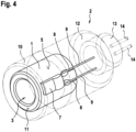
- the electrical sensor 2 of the Fig. 3 also has wired measuring resistors as components 7. This means that the measuring resistors are provided with connecting wires 9 (see Fig. 4 ), which are inserted into guide channels 8 when inserting the measuring resistors in holders 6 (see Fig. 4 ). This eliminates the step of electrically contacting the measuring resistors.
- the additional electrical component 13 arranged on the front side has connecting lines 14 which are led out of the component 13 on the front side (see Fig. 4 ).
- the Fig. 5 1 shows a carrier element 1 according to the invention for forming an electrical sensor 2, which has two wired measuring resistors as electrical components 7.
- the tubular support element 1 does not have a circular cross-section, but a square cross-section.
- the support element 1 has both a square outer contour and a square inner contour in cross-section. The outer and inner corners are each slightly rounded.
- the measuring resistors are accommodated, for example, in two walls of the support element 1 arranged at a corner and delimiting the cavity 3, in each case in a surface 5 of the support element 1 facing away from the cavity 3.
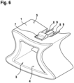
- FIG. 6 A further preferred embodiment of a carrier element 1 according to the invention for an electrical sensor 2 is shown in Fig. 6
- the carrier element 1 is also tubular, with the cross-section or cross-sectional shape of the carrier element 1 being based on a free form.
- the cavity 3 is delimited by walls that are curved to varying degrees of concave or convex.
- an electrical component 7 in the form of a measuring resistor is accommodated in a receptacle 6.
Landscapes
- Physics & Mathematics (AREA)
- General Physics & Mathematics (AREA)
- Fluid Mechanics (AREA)
- Measuring Fluid Pressure (AREA)
- Measuring Volume Flow (AREA)
Priority Applications (6)
| Application Number | Priority Date | Filing Date | Title |
|---|---|---|---|
| ES18180460T ES3012406T3 (en) | 2018-06-28 | 2018-06-28 | Electrical sensor |
| PT181804600T PT3588028T (pt) | 2018-06-28 | 2018-06-28 | Sensor elétrico |
| FIEP18180460.0T FI3588028T3 (en) | 2018-06-28 | 2018-06-28 | ELECTRIC SENSOR |
| DK18180460.0T DK3588028T3 (da) | 2018-06-28 | 2018-06-28 | Elektrisk sensor |
| PL18180460.0T PL3588028T3 (pl) | 2018-06-28 | 2018-06-28 | Czujnik elektryczny |
| EP18180460.0A EP3588028B1 (de) | 2018-06-28 | 2018-06-28 | Elektrischer sensor |
Applications Claiming Priority (1)
| Application Number | Priority Date | Filing Date | Title |
|---|---|---|---|
| EP18180460.0A EP3588028B1 (de) | 2018-06-28 | 2018-06-28 | Elektrischer sensor |
Publications (2)
| Publication Number | Publication Date |
|---|---|
| EP3588028A1 EP3588028A1 (de) | 2020-01-01 |
| EP3588028B1 true EP3588028B1 (de) | 2024-11-27 |
Family
ID=62816403
Family Applications (1)
| Application Number | Title | Priority Date | Filing Date |
|---|---|---|---|
| EP18180460.0A Active EP3588028B1 (de) | 2018-06-28 | 2018-06-28 | Elektrischer sensor |
Country Status (6)
| Country | Link |
|---|---|
| EP (1) | EP3588028B1 (pl) |
| DK (1) | DK3588028T3 (pl) |
| ES (1) | ES3012406T3 (pl) |
| FI (1) | FI3588028T3 (pl) |
| PL (1) | PL3588028T3 (pl) |
| PT (1) | PT3588028T (pl) |
Family Cites Families (6)
| Publication number | Priority date | Publication date | Assignee | Title |
|---|---|---|---|---|
| JPS6145462Y2 (pl) * | 1981-04-17 | 1986-12-20 | ||
| CH673061A5 (en) | 1987-07-13 | 1990-01-31 | Landis & Gyr Gmbh | Resistance thermometer with unstressed sensing element in housing - has annular grooves around sheath of cable end pressed into housing protecting element against bending stresses |
| WO2011042023A1 (en) * | 2009-10-05 | 2011-04-14 | Nkt Flexibles I/S | A flexible unbonded oil pipe system with an optical fiber sensor inside |
| DE102013200772A1 (de) * | 2013-01-18 | 2014-07-24 | Robert Bosch Gmbh | Kühlsystem zur Temperierung einer Batterie |
| DE102014118206A1 (de) | 2014-12-09 | 2016-06-09 | Endress + Hauser Wetzer Gmbh + Co. Kg | Temperaturfühler |
| US10415609B2 (en) * | 2016-03-29 | 2019-09-17 | Bitzer Kuehlmaschinenbau Gmbh | Insulating sleeve |
-
2018
- 2018-06-28 PL PL18180460.0T patent/PL3588028T3/pl unknown
- 2018-06-28 EP EP18180460.0A patent/EP3588028B1/de active Active
- 2018-06-28 FI FIEP18180460.0T patent/FI3588028T3/en active
- 2018-06-28 DK DK18180460.0T patent/DK3588028T3/da active
- 2018-06-28 PT PT181804600T patent/PT3588028T/pt unknown
- 2018-06-28 ES ES18180460T patent/ES3012406T3/es active Active
Also Published As
| Publication number | Publication date |
|---|---|
| DK3588028T3 (da) | 2025-02-17 |
| PL3588028T3 (pl) | 2025-05-19 |
| PT3588028T (pt) | 2025-02-06 |
| FI3588028T3 (en) | 2025-02-24 |
| ES3012406T3 (en) | 2025-04-09 |
| EP3588028A1 (de) | 2020-01-01 |
Similar Documents
| Publication | Publication Date | Title |
|---|---|---|
| DE4237224C2 (de) | Temperaturfühler | |
| DE19580281C2 (de) | Magnetsensor | |
| DE10207361B4 (de) | Ölzustandssensor und Verfahren zum Herstellen desselben | |
| EP3198250B1 (de) | Steckergehäuse für eine sensorvorrichtung und steckermodul | |
| DE102006035000B4 (de) | Sensorvorrichtung und Verfahren zu deren Fertigung | |
| EP1926999B1 (de) | Grundmodul für einen bewegungssensor | |
| EP2180951B1 (de) | Durchflusssensor und herstellungsverfahren dafür | |
| WO1996035929A1 (de) | Kapazitiver füllstandsensor | |
| EP1239266A2 (de) | Verfahren zur Herstellung eines Gehäuses für Sensorelemente, sowie Sensor, und dessen Verwendung | |
| DE19936300A1 (de) | Druckerkennungsvorrichtung, Verbindungsteil hierfür, sowie Verfahren zur Herstellung eines elektrischen Bauteileverbinders | |
| DE102012204911B4 (de) | Stützeinheit für eine Leiterplatte in einer Sensoreinheit und korrespondierende Sensoreinheit | |
| DE102004026210B4 (de) | Vorrichtung zur Erfassung einer physikalischen Größe und Gehäuse für eine Anordnung zur Messung einer physikalischen Größe | |
| DE102005042549A1 (de) | Thermo-Strömungsratensensor und Verfahren zu dessen Herstellung | |
| EP3227642A1 (de) | Sensoranordnung | |
| EP3108213B1 (de) | Sensoranordnung zur bestimmung wenigstens eines parameters eines durch einen kanal strömenden fluiden mediums | |
| DE102018113130A1 (de) | Elektrikverbindungsstruktur und Herstellverfahren hierfür | |
| EP0926474A1 (de) | Probe | |
| EP1239273A1 (de) | Sensor, insbesondere Temperatur-Sensor | |
| EP3227641B1 (de) | Sensoranordnung | |
| EP3588028B1 (de) | Elektrischer sensor | |
| DE10311521A1 (de) | Sensorelement, insbesondere Ölstandssensorelement, sowie Fluidsensor damit | |
| EP2679963A2 (de) | Messvorrichtung zum Bestimmen einer Prozessgröße | |
| EP3009811B1 (de) | Sensoranordnung und verfahren zur herstellung einer sensoranordnung | |
| DE10116019B4 (de) | Sensor sowie Verfahren zu dessen Herstellung | |
| WO2017076486A1 (de) | Messeinrichtung zum erfassen wenigstens eines messwerts eines fluiden mediums |
Legal Events
| Date | Code | Title | Description |
|---|---|---|---|
| PUAI | Public reference made under article 153(3) epc to a published international application that has entered the european phase |
Free format text: ORIGINAL CODE: 0009012 |
|
| STAA | Information on the status of an ep patent application or granted ep patent |
Free format text: STATUS: THE APPLICATION HAS BEEN PUBLISHED |
|
| AK | Designated contracting states |
Kind code of ref document: A1 Designated state(s): AL AT BE BG CH CY CZ DE DK EE ES FI FR GB GR HR HU IE IS IT LI LT LU LV MC MK MT NL NO PL PT RO RS SE SI SK SM TR |
|
| AX | Request for extension of the european patent |
Extension state: BA ME |
|
| STAA | Information on the status of an ep patent application or granted ep patent |
Free format text: STATUS: REQUEST FOR EXAMINATION WAS MADE |
|
| 17P | Request for examination filed |
Effective date: 20200630 |
|
| RBV | Designated contracting states (corrected) |
Designated state(s): AL AT BE BG CH CY CZ DE DK EE ES FI FR GB GR HR HU IE IS IT LI LT LU LV MC MK MT NL NO PL PT RO RS SE SI SK SM TR |
|
| STAA | Information on the status of an ep patent application or granted ep patent |
Free format text: STATUS: EXAMINATION IS IN PROGRESS |
|
| 17Q | First examination report despatched |
Effective date: 20201118 |
|
| GRAP | Despatch of communication of intention to grant a patent |
Free format text: ORIGINAL CODE: EPIDOSNIGR1 |
|
| STAA | Information on the status of an ep patent application or granted ep patent |
Free format text: STATUS: GRANT OF PATENT IS INTENDED |
|
| INTG | Intention to grant announced |
Effective date: 20240104 |
|
| GRAJ | Information related to disapproval of communication of intention to grant by the applicant or resumption of examination proceedings by the epo deleted |
Free format text: ORIGINAL CODE: EPIDOSDIGR1 |
|
| STAA | Information on the status of an ep patent application or granted ep patent |
Free format text: STATUS: EXAMINATION IS IN PROGRESS |
|
| INTC | Intention to grant announced (deleted) | ||
| GRAP | Despatch of communication of intention to grant a patent |
Free format text: ORIGINAL CODE: EPIDOSNIGR1 |
|
| STAA | Information on the status of an ep patent application or granted ep patent |
Free format text: STATUS: GRANT OF PATENT IS INTENDED |
|
| INTG | Intention to grant announced |
Effective date: 20240702 |
|
| GRAS | Grant fee paid |
Free format text: ORIGINAL CODE: EPIDOSNIGR3 |
|
| GRAA | (expected) grant |
Free format text: ORIGINAL CODE: 0009210 |
|
| STAA | Information on the status of an ep patent application or granted ep patent |
Free format text: STATUS: THE PATENT HAS BEEN GRANTED |
|
| AK | Designated contracting states |
Kind code of ref document: B1 Designated state(s): AL AT BE BG CH CY CZ DE DK EE ES FI FR GB GR HR HU IE IS IT LI LT LU LV MC MK MT NL NO PL PT RO RS SE SI SK SM TR |
|
| REG | Reference to a national code |
Ref country code: GB Ref legal event code: FG4D Free format text: NOT ENGLISH |
|
| REG | Reference to a national code |
Ref country code: CH Ref legal event code: EP |
|
| REG | Reference to a national code |
Ref country code: IE Ref legal event code: FG4D Free format text: LANGUAGE OF EP DOCUMENT: GERMAN |
|
| REG | Reference to a national code |
Ref country code: DE Ref legal event code: R096 Ref document number: 502018015352 Country of ref document: DE |
|
| P01 | Opt-out of the competence of the unified patent court (upc) registered |
Free format text: CASE NUMBER: APP_66952/2024 Effective date: 20241218 |
|
| REG | Reference to a national code |
Ref country code: PT Ref legal event code: SC4A Ref document number: 3588028 Country of ref document: PT Date of ref document: 20250206 Kind code of ref document: T Free format text: AVAILABILITY OF NATIONAL TRANSLATION Effective date: 20250131 |
|
| REG | Reference to a national code |
Ref country code: DK Ref legal event code: T3 Effective date: 20250214 |
|
| REG | Reference to a national code |
Ref country code: FI Ref legal event code: FGE |
|
| REG | Reference to a national code |
Ref country code: NL Ref legal event code: FP |
|
| REG | Reference to a national code |
Ref country code: SE Ref legal event code: TRGR |
|
| REG | Reference to a national code |
Ref country code: LT Ref legal event code: MG9D |
|
| REG | Reference to a national code |
Ref country code: ES Ref legal event code: FG2A Ref document number: 3012406 Country of ref document: ES Kind code of ref document: T3 Effective date: 20250409 |
|
| PG25 | Lapsed in a contracting state [announced via postgrant information from national office to epo] |
Ref country code: HR Free format text: LAPSE BECAUSE OF FAILURE TO SUBMIT A TRANSLATION OF THE DESCRIPTION OR TO PAY THE FEE WITHIN THE PRESCRIBED TIME-LIMIT Effective date: 20241127 Ref country code: IS Free format text: LAPSE BECAUSE OF FAILURE TO SUBMIT A TRANSLATION OF THE DESCRIPTION OR TO PAY THE FEE WITHIN THE PRESCRIBED TIME-LIMIT Effective date: 20250327 |
|
| PG25 | Lapsed in a contracting state [announced via postgrant information from national office to epo] |
Ref country code: BG Free format text: LAPSE BECAUSE OF FAILURE TO SUBMIT A TRANSLATION OF THE DESCRIPTION OR TO PAY THE FEE WITHIN THE PRESCRIBED TIME-LIMIT Effective date: 20241127 |
|
| PG25 | Lapsed in a contracting state [announced via postgrant information from national office to epo] |
Ref country code: LV Free format text: LAPSE BECAUSE OF FAILURE TO SUBMIT A TRANSLATION OF THE DESCRIPTION OR TO PAY THE FEE WITHIN THE PRESCRIBED TIME-LIMIT Effective date: 20241127 Ref country code: GR Free format text: LAPSE BECAUSE OF FAILURE TO SUBMIT A TRANSLATION OF THE DESCRIPTION OR TO PAY THE FEE WITHIN THE PRESCRIBED TIME-LIMIT Effective date: 20250228 |
|
| PG25 | Lapsed in a contracting state [announced via postgrant information from national office to epo] |
Ref country code: RS Free format text: LAPSE BECAUSE OF FAILURE TO SUBMIT A TRANSLATION OF THE DESCRIPTION OR TO PAY THE FEE WITHIN THE PRESCRIBED TIME-LIMIT Effective date: 20250227 |
|
| PG25 | Lapsed in a contracting state [announced via postgrant information from national office to epo] |
Ref country code: SM Free format text: LAPSE BECAUSE OF FAILURE TO SUBMIT A TRANSLATION OF THE DESCRIPTION OR TO PAY THE FEE WITHIN THE PRESCRIBED TIME-LIMIT Effective date: 20241127 |
|
| PGFP | Annual fee paid to national office [announced via postgrant information from national office to epo] |
Ref country code: FI Payment date: 20250626 Year of fee payment: 8 |
|
| PGFP | Annual fee paid to national office [announced via postgrant information from national office to epo] |
Ref country code: PL Payment date: 20250625 Year of fee payment: 8 |
|
| PGFP | Annual fee paid to national office [announced via postgrant information from national office to epo] |
Ref country code: GB Payment date: 20250626 Year of fee payment: 8 Ref country code: DK Payment date: 20250626 Year of fee payment: 8 |
|
| PGFP | Annual fee paid to national office [announced via postgrant information from national office to epo] |
Ref country code: NO Payment date: 20250627 Year of fee payment: 8 |
|
| PGFP | Annual fee paid to national office [announced via postgrant information from national office to epo] |
Ref country code: NL Payment date: 20250626 Year of fee payment: 8 Ref country code: BE Payment date: 20250626 Year of fee payment: 8 |
|
| PGFP | Annual fee paid to national office [announced via postgrant information from national office to epo] |
Ref country code: PT Payment date: 20250626 Year of fee payment: 8 |
|
| PG25 | Lapsed in a contracting state [announced via postgrant information from national office to epo] |
Ref country code: EE Free format text: LAPSE BECAUSE OF FAILURE TO SUBMIT A TRANSLATION OF THE DESCRIPTION OR TO PAY THE FEE WITHIN THE PRESCRIBED TIME-LIMIT Effective date: 20241127 |
|
| PGFP | Annual fee paid to national office [announced via postgrant information from national office to epo] |
Ref country code: FR Payment date: 20250626 Year of fee payment: 8 |
|
| PG25 | Lapsed in a contracting state [announced via postgrant information from national office to epo] |
Ref country code: RO Free format text: LAPSE BECAUSE OF FAILURE TO SUBMIT A TRANSLATION OF THE DESCRIPTION OR TO PAY THE FEE WITHIN THE PRESCRIBED TIME-LIMIT Effective date: 20241127 |
|
| PGFP | Annual fee paid to national office [announced via postgrant information from national office to epo] |
Ref country code: AT Payment date: 20250627 Year of fee payment: 8 |
|
| PG25 | Lapsed in a contracting state [announced via postgrant information from national office to epo] |
Ref country code: SK Free format text: LAPSE BECAUSE OF FAILURE TO SUBMIT A TRANSLATION OF THE DESCRIPTION OR TO PAY THE FEE WITHIN THE PRESCRIBED TIME-LIMIT Effective date: 20241127 |
|
| PG25 | Lapsed in a contracting state [announced via postgrant information from national office to epo] |
Ref country code: CZ Free format text: LAPSE BECAUSE OF FAILURE TO SUBMIT A TRANSLATION OF THE DESCRIPTION OR TO PAY THE FEE WITHIN THE PRESCRIBED TIME-LIMIT Effective date: 20241127 |
|
| PGFP | Annual fee paid to national office [announced via postgrant information from national office to epo] |
Ref country code: SE Payment date: 20250626 Year of fee payment: 8 |
|
| REG | Reference to a national code |
Ref country code: DE Ref legal event code: R097 Ref document number: 502018015352 Country of ref document: DE |
|
| PLBE | No opposition filed within time limit |
Free format text: ORIGINAL CODE: 0009261 |
|
| STAA | Information on the status of an ep patent application or granted ep patent |
Free format text: STATUS: NO OPPOSITION FILED WITHIN TIME LIMIT |
|
| PGFP | Annual fee paid to national office [announced via postgrant information from national office to epo] |
Ref country code: ES Payment date: 20250718 Year of fee payment: 8 |
|
| PGFP | Annual fee paid to national office [announced via postgrant information from national office to epo] |
Ref country code: DE Payment date: 20250627 Year of fee payment: 8 |
|
| PGFP | Annual fee paid to national office [announced via postgrant information from national office to epo] |
Ref country code: IT Payment date: 20250626 Year of fee payment: 8 |
|
| PGFP | Annual fee paid to national office [announced via postgrant information from national office to epo] |
Ref country code: CH Payment date: 20250724 Year of fee payment: 8 |
|
| 26N | No opposition filed |
Effective date: 20250828 |
|
| PG25 | Lapsed in a contracting state [announced via postgrant information from national office to epo] |
Ref country code: MC Free format text: LAPSE BECAUSE OF FAILURE TO SUBMIT A TRANSLATION OF THE DESCRIPTION OR TO PAY THE FEE WITHIN THE PRESCRIBED TIME-LIMIT Effective date: 20241127 |
|
| PG25 | Lapsed in a contracting state [announced via postgrant information from national office to epo] |
Ref country code: LU Free format text: LAPSE BECAUSE OF NON-PAYMENT OF DUE FEES Effective date: 20250628 |
|
| PG25 | Lapsed in a contracting state [announced via postgrant information from national office to epo] |
Ref country code: IE Free format text: LAPSE BECAUSE OF NON-PAYMENT OF DUE FEES Effective date: 20250628 |