EP3588004A1 - Stereoscopic camera and height acquisition method therefor and height acquisition system - Google Patents
Stereoscopic camera and height acquisition method therefor and height acquisition system Download PDFInfo
- Publication number
- EP3588004A1 EP3588004A1 EP18756576.7A EP18756576A EP3588004A1 EP 3588004 A1 EP3588004 A1 EP 3588004A1 EP 18756576 A EP18756576 A EP 18756576A EP 3588004 A1 EP3588004 A1 EP 3588004A1
- Authority
- EP
- European Patent Office
- Prior art keywords
- stereo camera
- distance
- dimensional point
- plane
- height
- Prior art date
- Legal status (The legal status is an assumption and is not a legal conclusion. Google has not performed a legal analysis and makes no representation as to the accuracy of the status listed.)
- Granted
Links
Images



Classifications
-
- G—PHYSICS
- G06—COMPUTING OR CALCULATING; COUNTING
- G06T—IMAGE DATA PROCESSING OR GENERATION, IN GENERAL
- G06T7/00—Image analysis
- G06T7/70—Determining position or orientation of objects or cameras
-
- G—PHYSICS
- G06—COMPUTING OR CALCULATING; COUNTING
- G06T—IMAGE DATA PROCESSING OR GENERATION, IN GENERAL
- G06T7/00—Image analysis
- G06T7/50—Depth or shape recovery
- G06T7/55—Depth or shape recovery from multiple images
- G06T7/593—Depth or shape recovery from multiple images from stereo images
-
- G—PHYSICS
- G06—COMPUTING OR CALCULATING; COUNTING
- G06T—IMAGE DATA PROCESSING OR GENERATION, IN GENERAL
- G06T7/00—Image analysis
- G06T7/80—Analysis of captured images to determine intrinsic or extrinsic camera parameters, i.e. camera calibration
-
- H—ELECTRICITY
- H04—ELECTRIC COMMUNICATION TECHNIQUE
- H04N—PICTORIAL COMMUNICATION, e.g. TELEVISION
- H04N13/00—Stereoscopic video systems; Multi-view video systems; Details thereof
- H04N13/20—Image signal generators
- H04N13/204—Image signal generators using stereoscopic image cameras
-
- H—ELECTRICITY
- H04—ELECTRIC COMMUNICATION TECHNIQUE
- H04N—PICTORIAL COMMUNICATION, e.g. TELEVISION
- H04N23/00—Cameras or camera modules comprising electronic image sensors; Control thereof
- H04N23/60—Control of cameras or camera modules
- H04N23/66—Remote control of cameras or camera parts, e.g. by remote control devices
-
- G—PHYSICS
- G06—COMPUTING OR CALCULATING; COUNTING
- G06T—IMAGE DATA PROCESSING OR GENERATION, IN GENERAL
- G06T2207/00—Indexing scheme for image analysis or image enhancement
- G06T2207/10—Image acquisition modality
- G06T2207/10004—Still image; Photographic image
- G06T2207/10012—Stereo images
-
- G—PHYSICS
- G06—COMPUTING OR CALCULATING; COUNTING
- G06T—IMAGE DATA PROCESSING OR GENERATION, IN GENERAL
- G06T2207/00—Indexing scheme for image analysis or image enhancement
- G06T2207/20—Special algorithmic details
- G06T2207/20024—Filtering details
- G06T2207/20032—Median filtering
-
- G—PHYSICS
- G06—COMPUTING OR CALCULATING; COUNTING
- G06T—IMAGE DATA PROCESSING OR GENERATION, IN GENERAL
- G06T2207/00—Indexing scheme for image analysis or image enhancement
- G06T2207/20—Special algorithmic details
- G06T2207/20072—Graph-based image processing
-
- G—PHYSICS
- G06—COMPUTING OR CALCULATING; COUNTING
- G06T—IMAGE DATA PROCESSING OR GENERATION, IN GENERAL
- G06T2207/00—Indexing scheme for image analysis or image enhancement
- G06T2207/30—Subject of image; Context of image processing
- G06T2207/30244—Camera pose
-
- H—ELECTRICITY
- H04—ELECTRIC COMMUNICATION TECHNIQUE
- H04N—PICTORIAL COMMUNICATION, e.g. TELEVISION
- H04N13/00—Stereoscopic video systems; Multi-view video systems; Details thereof
- H04N2013/0074—Stereoscopic image analysis
- H04N2013/0081—Depth or disparity estimation from stereoscopic image signals
Definitions
- the present disclosure relates to the field of application of electronic technology, and particularly to a stereo camera, and height acquisition method and height acquisition system thereof.
- Stereo cameras are cameras for reconstructing three-dimensional geometric information of a scenario.
- the stereo camera includes, but not limited to, a binocular stereo camera, a time of flight (TOF) stereo camera or the like which is capable of acquiring the three-dimensional information.
- TOF time of flight
- a stereo vision camera before image capture and analysis, camera parameters need to be predefined, wherein the camera parameters may include an internal parameter (abbr.: IP) and an external parameter (abbr.: EP).
- the external parameter may include at least one of the parameter: a pitch angle, a tilt angle and a height.
- an external reference structure needs to be defined.
- a calibration plate may be arranged to keep coincidence with the world coordinate system to acquire coordinates of characteristic points on the calibration plate.
- the calibration plate needs to be removed, such that central point three-dimensional points sampling is performed at different positions on the calibration plate, and the height of the stereo vision camera is determined by calculating a conversion matrix.
- Examples of the present disclosure provide a stereo camera, and a height acquisition method and system thereof., such that the problems that determining a height by defining an external reference structure is complicated in operation and needs a high cost.
- the specific technical solutions are as follows:
- a method for acquiring a height of a stereo camera, applied to the stereo camera comprising:
- the determining height of the stereo camera based on the angle information and the three-dimensional point set comprises:
- determining, based on the pitch angle and the tilt angle, a reference plane equation corresponding to a reference plane comprises:
- the determining the height of the stereo camera based on the distances in the distance set comprises:
- the determining the height of the stereo camera based on the distances in the distance set comprises:
- the ground image includes a plurality of contiguous ground images captured by the stereo camera; and wherein the determining depth information of each pixel on the ground image, comprises: performing median filtering in time domain on the plurality of contiguous ground images to obtain a plurality of ground images after median filtering in time domain; performing median filtering in space domain on the plurality of ground images after median filtering in time domain to obtain a plurality of ground images after median filtering in space domain; and determining depth information of each pixel on the ground images after median filtering in space domain.
- the acquiring angle information of the stereo camera comprises: acquiring the angle information of the stereo camera by an angle sensor in the stereo camera.
- a stereo camera comprising:
- the second determining module comprises:
- the second determining sub-module is further configured to:
- the second determining sub-module comprises:
- the ground image includes a plurality of contiguous ground images captured by the stereo camera; and the first determining module is further configured to:
- the acquiring module is further configured to: acquire the angle information of the stereo camera by an angle sensor in the stereo camera.
- the stereo camera is a binocular stereo camera or a time of flight (TOF) stereo camera.
- TOF time of flight
- a stereo camera comprising:
- the memory stores at least one program, configured to be executed by the at least one processing component, and configured to be executed by the at least one processing component to perform the method for acquiring height of stereo camera as defined in any one of stereo cameras above.
- a height acquisition system comprises:
- a height acquisition system comprising: a remote control apparatus and a stereo camera; wherein the stereo camera is configured to:
- examples of the present disclosure provide a stereo camera, method and system for acquiring a height of stereo camera thereof, the ground image of the scenario where the stereo vision camera is deployed is captured, then the three-dimensional point set recording coordinate information of each three-dimensional point corresponding to each pixel on the ground image is determined based on depth information of each pixel on the ground image, and the height of the stereo camera is determined based on the angle information and the three-dimensional point set.
- the stereo camera automatically determines the height thereof without defining an external reference structure, such that the operation complexity is lowered, and the cost for determining the height is reduced.
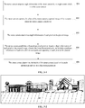
- FIG. 1 is a schematic diagram of an implementation scenario of a height acquisition method of a stereo camera according to examples of the present disclosure.
- a stereo camera 110 is located indoors or outdoors.
- a camera parameter of a conventional stereo camera may be predefined, wherein the camera parameter may include an internal parameter (abbr.: IP) and an external parameter (abbr.: EP).
- the external parameter may include: a pitch angle, a tilt angle and height.
- Calibration of the external parameters of the stereo camera is a premise and basis for three-dimensional measurement of the stereo camera, and is one of the most important parts for ensuring precision of an image processing result of the stereo camera.
- An incorrect camera external parameter may interfere the visual analysis for the stereo camera.
- height of the stereo camera is height Ht thereof in a world coordinate system, which may be generally a distance from a central point of a lens of the stereo camera to a horizon W in the world coordinate system.
- the central point is an origin of a camera coordinate system of the stereo camera.
- the camera coordinate system is a plane coordinate system
- the horizon W is a plane extracted from the ground.
- the stereo camera captures a ground image of a scenario where the stereo camera is deployed, and the height of the stereo camera is determined based on the ground image and pre-acquired angle information.
- the stereo camera may include a processing component, an angle sensor (also known as a gyroscope) and a lens.
- the processing component may be a processor or a processing chip.
- the lens is configured to capture the ground image of the scenario where the stereo camera is deployed.
- the processing component is configured to determine the height of the stereo camera based on the ground image and the angle information pre-acquired by the angle sensor.
- examples of the present disclosure provide a method for acquiring a height of a stereo camera, which is applied to the stereo camera as illustrated in FIG. 1 .
- the method includes:
- the ground image of the scenario where the stereo camera is deployed is captured, and the three-dimensional point set including coordinate information of each three-dimensional point corresponding to each pixel on the ground image is determined based on depth information of each pixel on the ground image, and the height of the stereo camera is determined based on the angle information and the three-dimensional point set.
- the stereo camera may automatically determine the height without a definition for an external reference structure, and thereby lowing the operation complexity, and reducing cost for determining the height.
- examples of the present disclosure provide a method for acquiring height of a stereo camera, which is applied to the stereo camera as illustrated in FIG. 1 .
- the height of the stereo camera in a world coordinate system may be determined.
- the stereo camera may be a binocular stereo camera, a TOF stereo camera or the like, that is capable of acquiring stereo three-dimensional information.
- the method includes the following steps: Step 301: The stereo camera acquires angle information of the stereo camera by an angle sensor which is in the stereo camera.
- the angle information includes a pitch angle and a tilt angle.
- the angle sensor may be arranged in the stereo camera to measure angle information of the stereo camera. Precisions of a pitch angle and a tilt angle acquired by the angle sensor are generally high.
- the angle sensor may be an angle sensor chip, a highly integrated chip may save space in the stereo camera.
- Step 302 The stereo camera captures, by a lens of the stereo camera, a ground image of the scenario where the stereo camera is deployed.
- the stereo camera may be maintained at a current state, and may automatically capture a scenario image of a scenario where the stereo camera is deployed.
- the scenario image includes a ground image.
- the scenario image includes one image, or a plurality of contiguous images, or a plurality of frames in a video.
- the stereo camera may extract a ground image from the scenario image, and perform following processing on the image, or the stereo camera may directly perform following processing on the ground image in the scenario image.
- Step 303 The stereo camera determines depth information of each pixel on the ground image.
- a depth of an image refers to the number of bits used for storing each pixel in the image.
- the depth of an image may be used to measure a color resolution of the image.
- the depth information is also information for describing the depth of the image.
- the ground image (for example, a parallax image captured by a binocular stereo camera, or a depth image captured by a TOF stereo camera) acquired by the stereo camera may contain noise.
- the acquired ground image may be pre-processed to ensure accuracy of the depth information.
- the stereo camera may capture a plurality of ground images, and generally the stereo camera may continuously capture within a predefined time duration to obtain a plurality of scenario images, and thus to obtain a plurality of ground images (each ground image may be a scenario image, or each ground image may be an image of a ground region in the corresponding scenario image).
- a video may also be captured, and a plurality of contiguous frames in the video may be used as the scenario images to obtain a plurality of ground images.
- a median filtering in time domain is performed on the plurality of contiguous ground images to obtain a plurality of ground images after median filtering in time domain; then a median filtering in space domain is performed on the plurality of ground images after median filtering in time domain to obtain a plurality of ground images after median filtering in space domain; and then depth information of each pixel on the ground images after median filtering in space domain is determined.
- performing the median filtering in time domain on the plurality of contiguous ground images refers to performing the median filtering in time domain on a corresponding pixel on each of the plurality of contiguous ground images, until the median filtering in time domain is performed on each pixel on ground images.
- the median filtering in time domain may filter out information of inaccurate parallax caused by incorrect parallax calculation for an image
- the median filtering in space domain may filter out information of failure to calculate the parallax at a specific position in a specific scenario.
- whether to perform the median filtering in time domain and the median filtering in space domain is determined based on the quality of an imaging the stereo camera captured. If the stereo camera has better performance and high precision, and the captured image meets the calculation requirement, the median filtering in time domain and the median filtering in space domain are not necessary. If the stereo camera has poor performance and low precision, and the captured image fails to satisfy the calculation requirement, the median filtering in time domain and/or the median filtering in space domain is necessary.
- the process of determining depth information of each pixel on the ground image by the stereo camera may be implemented by conventional methods.
- the stereo camera is a binocular stereo camera
- a synchronous exposure image may be obtained by using the calibrated two cameras based on the bionics principle, and then three-dimensional depth information of each pixel on the acquired two-dimensional image is calculated.
- Step 304 The stereo camera establishes a three-dimensional point set based on depth information of each pixel on the ground image, wherein the three-dimensional point set includes coordinate information of each three-dimensional point corresponding to each pixel on the ground image.
- the stereo camera may determine coordinate information of each three-dimensional point based on the depth information of corresponding pixel on the ground image, and add the coordinate information of each three-dimensional point in the three-dimensional point set.
- the coordinate information may be coordinate values of each three-dimensional point in the world coordinate system. For example, assuming that the scenario image captured by the stereo camera in step 302 is as illustrated in FIG. 3-2 , the ground image is an image corresponding to a region M (that is, a dotted-line region in FIG. 3-2 ), then the value of the three-dimensional point corresponding to the pixel x in the world coordinate system in a practical scenario of the scenario image may be determined based on the depth information of any pixel x in the region M.
- the stereo camera determines the three-dimensional point set based on the depth information of each pixel on the ground image
- the each three-dimensional point may be screened in advance to exclude three-dimensional points having unqualified coordinate information to obtain a more accurate three-dimensional point set. In this way, the accuracy of the height of the stereo camera that is subsequently determined is improved.
- the stereo camera when the stereo camera is a binocular stereo camera, the ground image is a parallax image, and the stereo camera may determine whether the parallax corresponding to each pixel on the ground image is within a predefined parallax range.
- the pixel is excluded, that is, the coordinate information of the three-dimensional point corresponding to the pixel is not added to the three-dimensional point set.
- the parallax corresponding to a pixel is within the predefined parallax range, the coordinate information of the three-dimensional point corresponding to the pixel is determined, and the coordinate information of the three-dimensional point is added to the three-dimensional point set.
- the stereo camera when the stereo camera is a TOF stereo camera, the ground image is a depth image, and the stereo camera may determine whether the depth corresponding to each pixel on the ground image is within a predefined depth range.
- the pixel is excluded, that is, the coordinate information of the three-dimensional point corresponding to the pixel is not added to the three-dimensional point set.
- the coordinate information of the three-dimensional point corresponding to the pixel is determined, and the coordinate information of the three-dimensional point is added to the three-dimensional point set.
- Step 305 The stereo camera determines the height of the stereo camera based on the angle information and the three-dimensional point set.
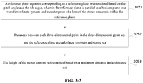
- the method for determining the height of the stereo camera based on the angle information and the three-dimensional point set may be as illustrated in FIG. 3-3 , and include the following steps: Step 3051: A reference plane equation corresponding to a reference plane is determined based on the pitch angle and the tilt angle, wherein the reference plane is parallel to a horizon plane in a world coordinate system, and a center point of a lens of the stereo camera is within the reference plane.
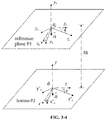
- FIG. 3-4 is a schematic diagram of a relation between a world coordinate system and a camera coordinate system.
- variables (x, y, z) respectively represent coordinate axes of the stereo camera in the world coordinate system
- variables (xc, yc, zc) respectively represent coordinate axes of the stereo camera in the camera coordinate system
- variables (xr, yr, zr) respectively represent coordinate axes of the stereo camera in a world reference coordinate system
- the world reference coordinate system is a coordinate system when the world coordinate system is translated along a positive direction of the y axis thereof to coincide with the origin of the camera coordinate system.
- Variables (x'c, y'c, z'c) represent a coordinate system when the camera coordinate system is translated along a negative direction of y axis thereof to coincide with the origin of the world coordinate system, wherein the origin of the world reference coordinate system coincides with the origin of the camera coordinate system, and the coordinate axes of the world reference coordinate system are parallel to the coordinate axes of the world coordinate system. Both the origin of the world reference coordinate system and the origin of the camera coordinate system are the central point of the lens of the stereo camera.
- a point corresponding to the end position of the vector (0, 1, 0) is (a, b, c)
- n (a,b,c)
- the reference plane P1 is parallel to a horizon plane P2 of the world coordinate system.
- the process of determining a reference plane equation corresponding to a reference plane based on the pitch angle and the tilt angle includes:
- Step 3052 Distances between each three-dimensional point in the three-dimensional point set and the reference plane are calculated to obtain a distance set.
- the distance sent includes a plurality of distances corresponding to the three-dimensional point set.
- a coordinate of a point in the three-dimensional point set is (2, 2, 2)
- Step 3503 The height of the stereo camera is determined based on a maximum distance in the distance set.
- the method for determining the height of the stereo camera based on the maximum distance in the distance set may be performed in a plurality of implementation ways. The following two implementation manners are described as examples of the present disclosure:
- the maximum distance in may be directly determined as the height of the stereo camera, that is, the maximum distance in distances between each three-dimensional point and the reference plane is determined as the height of the stereo camera.
- the first implementation manner for determining the height is relatively simple.
- the height of the stereo camera may be determined based on a histogram.
- the second implementation manner for determining the height achieves a high precision.
- the second implementation manner includes the following steps: Step a: A predefined width is determined as a class width, and then a distance histogram is established by counting the distance set, wherein a width in a horizontal axis of each rectangular column in the distance histogram indicates a distance range, and a length in a vertical axis of each rectangular column in the distance histogram indicates the number of distances within the distance range.
- the number of distances within the distance range is the number of corresponding distances in three-dimensional points within the corresponding distance range.
- the height of the stereo camera may be determined based on the distances between each of the plurality of three-dimensional points and the reference plane, wherein a visual manner to count distance is the distance histogram.
- the predefined width is 10 cm
- the class width is determined as 10 cm
- the class width may be determined as a step for drawing the histogram, and the distance histogram is established by counting the distance set.
- the horizontal axis of the histogram is in centimeters; (in examples of the present disclosure, the unit of the horizontal axis of the histogram may be defined according to the specific situation, and FIG.
- the vertical axis of the histogram is in pieces.
- the width in the horizontal axis of each rectangular column in the histogram represents the distance range
- the length in the vertical axis of each rectangular column in the histogram represents the number of distances in the distance set within the distance range.
- the width of a rectangular column L in the horizontal axis represents a distance range is: 50 to 60 cm
- the length in the vertical axis of the rectangular column represents the number of distances in the distance sent within the distance range of 50 to 60 cm is: 60.
- Step b A middle point of the width in the horizontal axis of a rectangular column, corresponding to a maximum distance range in the distance histogram, is determined as a pre-selected height value H.
- the rectangular column including the maxim distance is a rectangular column corresponding to a maximum distance range.
- the rectangular column including the maximum distance is a rectangular column Q, (that is, the rectangular column corresponding to the maximum distance range is the rectangular column Q), the corresponding distance range of the rectangular column Q is 90 to 100 cm, and a middle point of width in the horizontal axis of the rectangular column Q is 95.
- the pre-selected height value H is 95.
- the pre-selected height value may be directly determined as height value of the external parameters.
- Step b is actually a rough selection of the height
- step c is actually an accurate selection of the height.
- ⁇ is 2
- Step d Distances between each three-dimensional point and each pre-selected plane are obtained based on the three-dimensional point set and the set of pre-selected plane.
- distances between each three-dimensional point in the three-dimensional point set and each pre-selected plane in the set of pre-selected plane may be re-counted by the second distance calculation equation above.
- a coordinate of a point in the three-dimensional point set is (2, 2, 2)
- Step e For each pre-selected plane, a three-dimensional point having a distance between the three-dimensional point and the pre-selected plane being greater than a predefined support threshold is determined as a support point of the pre-selected plane.
- the predefined support threshold is ht
- a distance Hi' between the i th three-dimensional point (x i , y i , z i ) and the first pre-selected plane is obtained by the second distance calculation formula, Hi' > ht
- Step f A pre-selected plane having the largest number of support points in the set of pre-selected plane is determined as a target plane.
- the pre-selected plane having the largest number of support points in the set of pre-selected plane may be determined as the target plane.
- the target plane may represent the horizon plane of the world coordinate system.
- Step g An average value of distances between all the support points in the target plane and the reference plane is determined as the height of the stereo camera.
- step a to step g the pre-selected height value is firstly determined based on the distance set by drawing a histogram, then the set of pre-selected plane is determined based on the pre-selected height value and the target plane representing the ground of the world coordinate system is determined, and finally an average value of the distances between each support point in the target plane and the reference plane is determined as the height of the stereo camera.
- a rough selection of the height is performed first, and then an accurate selection of the height is performed. In this way, the height of the stereo camera obtained has a high accuracy, and no dedicated external reference structure needs to be arranged.
- the above steps 303 to 305 may also be performed by a remote control device.
- the stereo camera acquires the angle information and the ground image of the stereo camera through steps 301 and 302
- the angle information and the ground image may be sent to the remote control apparatus.
- the remote control apparatus determines depth information of each pixel on a ground image, and then determines the three-dimensional point set based on depth information of each pixel on the ground image, and determines the height of the stereo camera based on the angle information and the three-dimensional point set.
- the remote control apparatus may be a computer or a server or the like device.
- examples of the present disclosure provide a method for acquiring height of a stereo camera, the ground image of the scenario where the stereo camera is deployed is captured, the three-dimensional point set which includes coordinate information of each three-dimensional point corresponding to each pixel on the ground image is determined based on depth information of each pixel on the ground image, and the height of the stereo camera is determined based on the angle information and the three-dimensional point set.
- the stereo camera may determine the height automatically thereof without defining an external reference structure, such that the operation complexity is lowered, and the cost for determining the height is reduced.
- the stereo camera may determine the height by referencing the ground image thereof. The way of determining the external parameters is concise, and has high robustness.
- the external reference structure since during determination of the height of the stereo camera, the external reference structure does not need to be set up, the operating personnel may not handle the on-site environment. Therefore, the staff does not need to handle the environment, and does not need to be in the vicinity of the stereo camera, and thereby the stereo camera could be controlled remotely.
- the stereo camera 40 includes:
- the second determining module 405 includes:
- the second determining sub-module is further configured to:
- the second determining sub-module includes:
- the ground image includes a plurality of contiguous ground images captured by the stereo camera; and the first determining module 403 is further configured to:
- the acquiring module 401 is further configured to: acquire the angle information of the stereo camera by an angle sensor in the stereo camera.
- the capturing module captures a ground image of a scenario where the stereo camera is deployed, the establishing module establishes the three-dimensional point set including coordinate information of each three-dimensional point corresponding to each pixel on the ground image, and the second determining module determines the height of the stereo camera based on the angle information and the three-dimensional point set.
- the stereo camera may determine the height automatically thereof without defining an external reference structure, such that the operation complexity is lowered, and the cost for determining the height is reduced.
- the stereo camera 50 includes:
- the processor 503 is further configured to establish a three-dimensional point set based on depth information of each pixel on the ground image, wherein the three-dimensional point set includes coordinate information of each three-dimensional point corresponding to each pixel on the ground image.
- the processor 503 is further configured to determine height of the stereo camera based on the angle information and the three-dimensional point set.
- the processor 503 is further configured to:
- the processor 503 is further configured to: determine a maximum distance in distances between each three-dimensional point and the reference plane as the height of the stereo camera.
- the ground image includes a plurality of contiguous ground images captured by the stereo camera; and the processor 503 is further configured to:
- the angle acquiring module 501 is an angle sensor, wherein the angle sensor is in the stereo camera.
- the stereo camera according to examples of the present disclosure is a binocular stereo camera or a TOF stereo camera.
- the camera captures the ground image of a scenario where the stereo camera is deployed, and the processor determines the three-dimensional point set which includes coordinate information of each three-dimensional point corresponding to each pixel on the ground image, and determines the height of the stereo camera based on the angle information and the three-dimensional point set.
- the stereo camera may determine the height automatically thereof without defining an external reference structure, such that the operation complexity is lowered, and the cost for determining the height is reduced.
- stereo camera includes:
- the stereo camera further includes an angle acquiring module, for example, an angle sensor, configured to acquire angle information of the stereo camera, wherein the angle information includes a pitch angle and a tilt angle; and a camera, configured to capture a ground image of a scenario where the stereo camera is deployed.
- an angle acquiring module for example, an angle sensor, configured to acquire angle information of the stereo camera, wherein the angle information includes a pitch angle and a tilt angle; and a camera, configured to capture a ground image of a scenario where the stereo camera is deployed.
- Examples of the present disclosure further provide a system for acquiring height of a stereo camera, the system includes: a remote control apparatus and a stereo camera; wherein the remote control apparatus is configured to remotely control the stereo camera; the remote control apparatus may be a smart phone, a computer, a wearable device, a server, or the like.
- the stereo camera is the stereo camera as described in above examples of the present disclosure.
- Examples of the present disclosure further provide system for acquiring height of a stereo camera, the system includes: a remote control apparatus and a stereo camera; wherein the remote control apparatus may be a smart phone, a computer, a wearable device, a server, or the like.
- the stereo camera is configured to: acquire angle information of the stereo camera (this process may be referenced to step 301 as described above), wherein the angle information includes a pitch angle and a tilt angle; capture a ground image of a scenario where the stereo camera is deployed (this process may be referenced to step 302 as described above); and send the angle information and the ground image to the remote control apparatus.
- the remote control apparatus is configured to: receive the angle information and the ground information; determine depth information of each pixel on the ground image (this process may be referenced to step 303 as described above); establish a three-dimensional point set based on depth information of each pixel on the ground image (this process may be referenced to step 304 as described above), wherein the three-dimensional point set includes coordinate information of each three-dimensional point corresponding to the each pixel on the ground image; and determine height of the stereo camera based on the angle information and the three-dimensional point set (this process may be referenced to step 305 as described above).
- the ground image of the scenario where the stereo camera is deployed is captured
- the three-dimensional point set includes coordinate information of the three-dimensional point corresponding to each pixel on the ground image is determined based on depth information of each pixel on the ground image
- the height of the stereo camera is determined based on the angle information and the three-dimensional point set.
- the stereo camera may automatically determine the height without a definition for an external reference structure, thereof lowing the operation complexity, and reducing cost for determining the height.
- the stereo camera may use the ground image as a reference to determine the height thereof. The way of determining the external parameters is concise, and has high robustness.
- the external reference structure is unnecessary during determination of the height of the stereo camera, the operating personnel may not handle the on-site environment. Therefore, the staff does not need to handle the environment, and no need to be in the vicinity of the stereo camera, thereby the stereo camera could be controlled remotely.
- the present disclosure further provides a non-transitory computer-readable storage medium, which stores code instructions; wherein the code instructions are executed by a processor to perform the height acquisition methods of a stereo camera as described in the above examples.
- the non-volatile computer-readable storage medium may be a read-only memory (ROM), a random access memory (RAM), a compact disc ROM (CD-ROM), a magnetic tape, a floppy disk, an optical data storage device or the like.
Landscapes
- Engineering & Computer Science (AREA)
- Computer Vision & Pattern Recognition (AREA)
- Physics & Mathematics (AREA)
- General Physics & Mathematics (AREA)
- Theoretical Computer Science (AREA)
- Multimedia (AREA)
- Signal Processing (AREA)
- Length Measuring Devices By Optical Means (AREA)
- Studio Devices (AREA)
- Image Processing (AREA)
- Measurement Of Optical Distance (AREA)
- Testing, Inspecting, Measuring Of Stereoscopic Televisions And Televisions (AREA)
Abstract
Description
- This application claims the benefit of priority to Chinese Application No.
201710100940.1, filed on February 23, 2017 - The present disclosure relates to the field of application of electronic technology, and particularly to a stereo camera, and height acquisition method and height acquisition system thereof.
- Stereo cameras are cameras for reconstructing three-dimensional geometric information of a scenario. The stereo camera includes, but not limited to, a binocular stereo camera, a time of flight (TOF) stereo camera or the like which is capable of acquiring the three-dimensional information.
- In a conventional stereo vision camera, before image capture and analysis, camera parameters need to be predefined, wherein the camera parameters may include an internal parameter (abbr.: IP) and an external parameter (abbr.: EP). The external parameter may include at least one of the parameter: a pitch angle, a tilt angle and a height. In the conventional methods for determining a height of a stereo vision camera, an external reference structure needs to be defined. For example, a calibration plate may be arranged to keep coincidence with the world coordinate system to acquire coordinates of characteristic points on the calibration plate. In addition, the calibration plate needs to be removed, such that central point three-dimensional points sampling is performed at different positions on the calibration plate, and the height of the stereo vision camera is determined by calculating a conversion matrix.
- However, determining the height by defining the external reference structure is complicated in operation and needs a high cost.
- Examples of the present disclosure provide a stereo camera, and a height acquisition method and system thereof., such that the problems that determining a height by defining an external reference structure is complicated in operation and needs a high cost. The specific technical solutions are as follows:
- According to a first aspect of the present disclosure, there is provided a method for acquiring a height of a stereo camera, applied to the stereo camera, the method comprising:
- acquiring angle information of a stereo camera, wherein the angle information includes a pitch angle and a tilt angle;
- capturing a ground image of a scenario where the stereo vision camera is deployed;
- determining depth information of each pixel on the ground image;
- establishing a three-dimensional point set based on the depth information of each pixel on the ground image, wherein the three-dimensional point set includes coordinate information of each three-dimensional point corresponding to each pixel of the ground image; and
- determining the height of the stereo camera based on the angle information and the three-dimensional point set.
- Optionally, wherein the determining height of the stereo camera based on the angle information and the three-dimensional point set, comprises:
- determining, based on the pitch angle and the tilt angle, a reference plane equation corresponding to a reference plane, wherein the reference plane is parallel to a horizon plane in a world coordinate system, and a center point of a lens of the stereo camera is within the reference plane;
- calculating distances between each three-dimensional point in the three-dimensional point set and the reference plane to obtain a distance set; and
- determining the height of the stereo camera based on the distances in the distance set.
- Optionally, wherein the determining, based on the pitch angle and the tilt angle, a reference plane equation corresponding to a reference plane, comprises:
- determining the reference plane equation ax+by+cz=0 based on the pitch angle θ and the tilt angle ϕ, such that a point (a, b, c) in a camera coordinate system meets an angle conversion equation:


- Optionally,
wherein the calculating distances between each three-dimensional point in the three-dimensional point set and the reference plane to obtain a distance set, comprises:
calculating a distance Hi between an ith three-dimensional point (xi, yi, zi) and the reference plane by using a first distance calculation equation based on the three-dimensional point set and the reference plane equation, wherein the distance set comprises the distance Hi, 1 ≤ i ≤ n, n being the total number of three-dimensional points in the three-dimensional point set, and the first distance calculation equation is:
- Optionally, wherein the determining the height of the stereo camera based on the distances in the distance set, comprises:
- combining the distances in the distance set to obtain a target distance set, wherein value of distances in the target distance set are different from each other, each distance has a number of times, and the times count value indicates a times count of occurrences of a corresponding distance in the distance set; and
- determining a distance corresponding a maximum number of times in the target distance set as the height of the stereo camera.
- Optionally, wherein the reference plane equation is ax+by+cz=0, a, b and c being coefficients of ax+by+cz=0; and
wherein the determining the height of the stereo camera based on the distances in the distance set, comprises: - forming, by a predefined width as a class width, a distance histogram according the distance set, wherein herein a width in a horizontal axis of each rectangular column in the distance histogram indicates a distance range, and a length in a vertical axis of each rectangular column in the distance histogram indicates the number of distances within the distance range;
- determining a middle point of width in the horizontal axis of a rectangular column having a maximum distance range in the distance histogram as a pre-selected height value H;
- traversing, by a predefined step, each adjacent height value h around the pre-selected height value H to obtain a set of pre-selected plane, wherein each pre-selected plane in the set of pre-selected plane meets the equation ax+by+cz+d=0, d=-h; and each adjacent height value h meets h ∈(h-σ, h+σ), σ being a predefined value, and σ being greater than or equal to the predefined step, and less than the predefined width;
- calculating distances between each three-dimensional point and each pre-selected plane based on the three-dimensional point set and the set of pre-selected plane;
- determining a three-dimensional point with the distance to the pre-selected plane being greater than a predefined support threshold as a support point of the pre-selected plane;
- determining a pre-selected plane having the most support points in the pre-selected planes set as a target plane; and
- determining an average value of distances between each support point in the target plane and the reference plane as the height of the stereo camera.
- Optionally, wherein the calculating distances between each three-dimensional point and each pre-selected plane based on the three-dimensional point set and the set of pre-selected plane, comprises:
calculating a distance Hi' between the ith three-dimensional point (xi, yi, zi) and the first pre-selected plane by a second distance calculation equation based on the three-dimensional point set and the set of pre-selected plane, wherein 1≤i≤n, n being the total number of three-dimensional points in the three-dimensional point set, and the second distance calculation equation being:
- Optionally, wherein the ground image includes a plurality of contiguous ground images captured by the stereo camera; and
wherein the determining depth information of each pixel on the ground image, comprises:
performing median filtering in time domain on the plurality of contiguous ground images to obtain a plurality of ground images after median filtering in time domain;
performing median filtering in space domain on the plurality of ground images after median filtering in time domain to obtain a plurality of ground images after median filtering in space domain; and
determining depth information of each pixel on the ground images after median filtering in space domain. - Optionally, wherein the acquiring angle information of the stereo camera comprises:
acquiring the angle information of the stereo camera by an angle sensor in the stereo camera. - According to a second aspect of the present disclosure, there is provided a stereo camera, comprising:
- an acquiring module, configured to angle information of a stereo camera, wherein the angle information includes a pitch angle and a tilt angle;
- a capturing module, configured to capture a ground image of a scenario where the stereo camera is deployed;
- a first determining module, configured to determine depth information of each pixel on the ground image;
- an establishing module, configured to establish a three-dimensional point set based on the depth information of each pixel on the ground image, wherein the three-dimensional point set includes coordinate information of each three-dimensional point corresponding to each pixel of the ground image; and
- a second determining module, configured to determine the height of the stereo camera based on the angle information and the three-dimensional point set.
- Optionally, wherein the second determining module comprises:
- a first determining sub-module, configured to determine, based on the pitch angle and the tilt angle, a reference plane equation corresponding to a reference plane, wherein the reference plane is parallel to a horizon plane in a world coordinate system, and a center point of a lens of the stereo camera is within the reference plane;
- a calculating sub-module, configured to calculate distances between each three-dimensional point in the three-dimensional point set and the reference plane to obtain a distance set; and
- a second determining module, configured to determine the height of the stereo camera based on the distances in the distance set.
- Optionally, wherein the first determining sub-module is further configured to:
determine the reference plane equation ax+by+cz=0 based on the pitch angle θ and the tilt angle ϕ, such that a point (a, b, c) in a camera coordinate system meets an angle conversion equation:

- Optionally, wherein the calculating sub-module is further configured to:
calculate a distance Hi between an ith three-dimensional point (xi, yi, zi) and the reference plane by using a first distance calculation equation based on the three-dimensional point set and the reference plane equation, wherein the distance set comprises the distance Hi, 1 ≤ i ≤ n, n being the total number of three-dimensional points in the three-dimensional point set, and the first distance calculation equation is:
- Optionally, wherein the second determining sub-module is further configured to:
- combine the distances in the distance set to obtain a target distance set, wherein distances in the target distance set are different from each other, each distance corresponds a number of times, and the number of times indicates a times count of occurrences of a corresponding distance in the distance set; and
- determine a distance corresponding a maximum number of times in the target distance set as the height of the stereo camera.
- Optionally, wherein the reference plane equation is ax+by+cz=0, a, b and c being coefficients of ax+by+cz=0;
the second determining sub-module comprises: - a histogram establishing sub-module, configured to form, by a predefined width as a class width, a distance histogram according the distance set, wherein herein a width in a horizontal axis of each rectangular column in the distance histogram indicates a distance range, and a length in a vertical axis of each rectangular column in the distance histogram indicates the number of distances within the distance range;
- a pre-selected value determining sub-module, configured to determine a middle point of width in the horizontal axis of a rectangular column corresponding to a maximum distance range in the distance histogram as a pre-selected height value H;
- a set determining sub-module, configured to traverse, by a predefined step, each adjacent height value h around the pre-selected height value H to obtained a set of pre-selected plane, wherein each pre-selected plane in the set of pre-selected plane meets the equation ax+by+cz+d=0, d=-h; and each adjacent height value h meets h∈(h-σ, h+σ), σ being a predefined value, and σ being greater than or equal to the predefined step, and less than the predefined width;
- a distance calculating sub-module, configured to calculate distances between each three-dimensional point and each pre-selected plane based on the three-dimensional point set and the set of pre-selected plane;
- a support point determining sub-module, configured to determine, for each pre-selected plane, a three-dimensional point having a distance between the three-dimensional point and the pre-selected plane being greater than a predefined support threshold as a support point of a pre-selected plane;
- a target plane determining sub-module, configured to determine a pre-selected plane having the most support points in the set of pre-selected planes as a target plane; and
- a height determining sub-module, configured to determine an average value of distances between all support points in the target plane and the reference plane as the height of the stereo camera.
- Optionally, wherein the distance calculating sub-module is further configured to:
calculate, based on the three-dimensional point set and the set of pre-selected plane, a distance Hi' between an ith three-dimensional point (xi, yi, zi) and a first pre-selected plane by a second distance calculation formula, wherein 1 ≤ i ≤ n, n being the total number of three-dimensional points in the three-dimensional point set, wherein the second distance calculation equation is as follows:
- Optionally, the ground image includes a plurality of contiguous ground images captured by the stereo camera; and
the first determining module is further configured to: - perform median filtering in time domain on the plurality of contiguous ground images to obtain ground images after median filtering in time domain;
- perform median filtering in space domain on each ground image after median filtering in time domain to the ground images after median filtering in space domain; and
- determine depth information of each pixel on ground images after median filtering in space domain.
- Optionally, where the acquiring module is further configured to:
acquire the angle information of the stereo camera by an angle sensor in the stereo camera. - Optionally, wherein the stereo camera is a binocular stereo camera or a time of flight (TOF) stereo camera.
- According to a third aspect of the present disclosure, there is provided a stereo camera, comprising:
- at least one processing component; and
- a memory;
- Wherein the memory stores at least one program, configured to be executed by the at least one processing component, and configured to be executed by the at least one processing component to perform the method for acquiring height of stereo camera as defined in any one of stereo cameras above.
- According to a fourth aspect of the present disclosure, there is provided a height acquisition system, comprises:
- a remote control apparatus and a stereo camera; wherein the remote control apparatus is configured to remotely control the stereo camera; and
- the stereo camera is the stereo camera above, or the stereo camera is the stereo camera above.
- According to a fifth aspect of the present disclosure, there is provided a height acquisition system, comprising: a remote control apparatus and a stereo camera; wherein
the stereo camera is configured to: - acquire angle information of the stereo camera, wherein the angle information includes a pitch angle and a tilt angle;
- capture a ground image of a scenario where the stereo vision camera is deployed; and
- send the angle information and the ground image to the remote control apparatus;
- the remote control apparatus is configured to:
- receive the angle information and the ground image;
- determine depth information of each pixel on the ground image;
- establish a three-dimensional point set based on depth information of each pixel on the ground image, wherein the three-dimensional point set includes coordinate information of each three-dimensional point corresponding to each pixel on the ground image; and
- determine height of the stereo camera based on the angle information and the three-dimensional point set. According to a fifth aspect of the present disclosure, there is provided a non-volatile computer-readable storage medium, which stores code instructions; wherein the code instructions are executed by a processor to perform the height acquisition method of a stereo camera as defined in the first aspect.
- The technical solutions according to examples of the present disclosure may achieve the following beneficial effects:
In summary, examples of the present disclosure provide a stereo camera, method and system for acquiring a height of stereo camera thereof, the ground image of the scenario where the stereo vision camera is deployed is captured, then the three-dimensional point set recording coordinate information of each three-dimensional point corresponding to each pixel on the ground image is determined based on depth information of each pixel on the ground image, and the height of the stereo camera is determined based on the angle information and the three-dimensional point set. In this way, the stereo camera automatically determines the height thereof without defining an external reference structure, such that the operation complexity is lowered, and the cost for determining the height is reduced. - It is to be understood that both the foregoing general description and the following detailed description are exemplary and explanatory only and are intended to limit the present disclosure.
- In order to describe the technical solutions in examples of the present more clearly, the following briefly introduces the accompanying drawings required for describing the examples. Apparently, the accompanying drawings in the following description show merely some examples of the present disclosure, and a person of ordinary skill in the art may also derive other drawings from these accompanying drawings without creative efforts.
-
FIG. 1 is a schematic diagram of an implementation scenario of a height acquisition method of a stereo camera according to examples of the present disclosure; -
FIG. 2 is a flowchart of a height acquisition method of a stereo camera according to examples of the present disclosure; -
FIG. 3-1 is a flowchart of another height acquisition method of a stereo camera according to examples of the present disclosure; -
FIG. 3-1 is a schematic diagram of a scenario image captured by a stereo camera according to examples of the present disclosure; -
FIG. 3-3 is a schematic flowchart of a method for determining a height of a stereo camera based on angle information and a three-dimensional point set according to examples of the present disclosure; -
FIG. 3-4 is a schematic diagram of a relation between a world coordinate system and a camera coordinate system according to examples of the present disclosure; -
FIGS. 3 to 5 are schematic diagrams of a histogram according to examples of the present disclosure; -
FIG. 4 is a schematic structural block diagram of a stereo camera according to examples of the present disclosure; and -
FIG. 5 is a schematic structural block diagram of another stereo camera according to examples of the present disclosure. - The accompanying drawings herein, which are incorporated into and constitute a part of the specification, illustrate examples consistent with the present disclosure, and together with the specification, serve to explain the principles of the present disclosure.
- For clearer descriptions of the objectives, technical solutions and advantages of the present disclosure, the present disclosure is further described in detail with reference to the accompanying drawings. Apparently, examples to be described hereinafter are merely some exemplary ones for illustrating the present disclosure, instead of all the examples. Based on the examples of the present disclosure, all other examples derived by persons of ordinary skill in the art without any creative efforts shall fall within the protection scope of the present disclosure.
- Referring to
FIG. 1, FIG. 1 is a schematic diagram of an implementation scenario of a height acquisition method of a stereo camera according to examples of the present disclosure. In this scenario, a stereo camera 110 is located indoors or outdoors. - Before capturing and analyzing an image, a camera parameter of a conventional stereo camera may be predefined, wherein the camera parameter may include an internal parameter (abbr.: IP) and an external parameter (abbr.: EP). The external parameter may include: a pitch angle, a tilt angle and height. Calibration of the external parameters of the stereo camera is a premise and basis for three-dimensional measurement of the stereo camera, and is one of the most important parts for ensuring precision of an image processing result of the stereo camera. An incorrect camera external parameter may interfere the visual analysis for the stereo camera. As illustrated in
FIG. 1 , height of the stereo camera is height Ht thereof in a world coordinate system, which may be generally a distance from a central point of a lens of the stereo camera to a horizon W in the world coordinate system. The central point is an origin of a camera coordinate system of the stereo camera. The camera coordinate system is a plane coordinate system, and the horizon W is a plane extracted from the ground. - In examples of the present disclosure, the stereo camera captures a ground image of a scenario where the stereo camera is deployed, and the height of the stereo camera is determined based on the ground image and pre-acquired angle information. The stereo camera may include a processing component, an angle sensor (also known as a gyroscope) and a lens. The processing component may be a processor or a processing chip. The lens is configured to capture the ground image of the scenario where the stereo camera is deployed. The processing component is configured to determine the height of the stereo camera based on the ground image and the angle information pre-acquired by the angle sensor.
- As illustrated in
FIG. 2 , examples of the present disclosure provide a method for acquiring a height of a stereo camera, which is applied to the stereo camera as illustrated inFIG. 1 . The method includes: - Step 201: Angle information of a stereo camera is acquired, wherein the angle information includes a pitch angle and a tilt angle;
- Step 202: A ground image of a scenario where the stereo camera is deployed is captured;
- Step 203: Depth information of each pixel on the ground image is determined;
- Step 204: A three-dimensional point set based on depth information of each pixel on the ground image is established, wherein the three-dimensional point set includes coordinate information of each three-dimensional point corresponding to each pixel of the ground image; and
- Step 205: The height of the stereo camera is determined based on the angle information and the three-dimensional point set.
- In summary, based on the method for acquiring the height of a stereo camera according to examples of the present disclosure, the ground image of the scenario where the stereo camera is deployed is captured, and the three-dimensional point set including coordinate information of each three-dimensional point corresponding to each pixel on the ground image is determined based on depth information of each pixel on the ground image, and the height of the stereo camera is determined based on the angle information and the three-dimensional point set. In this way, the stereo camera may automatically determine the height without a definition for an external reference structure, and thereby lowing the operation complexity, and reducing cost for determining the height.
- As illustrated in
FIG. 3-1 , examples of the present disclosure provide a method for acquiring height of a stereo camera, which is applied to the stereo camera as illustrated inFIG. 1 . According to the method, the height of the stereo camera in a world coordinate system may be determined. The stereo camera may be a binocular stereo camera, a TOF stereo camera or the like, that is capable of acquiring stereo three-dimensional information. The method includes the following steps:
Step 301: The stereo camera acquires angle information of the stereo camera by an angle sensor which is in the stereo camera. - In examples of the present disclosure, the angle information includes a pitch angle and a tilt angle. The angle sensor may be arranged in the stereo camera to measure angle information of the stereo camera. Precisions of a pitch angle and a tilt angle acquired by the angle sensor are generally high. The angle sensor may be an angle sensor chip, a highly integrated chip may save space in the stereo camera.
- Step 302: The stereo camera captures, by a lens of the stereo camera, a ground image of the scenario where the stereo camera is deployed.
- In examples of the present disclosure, the stereo camera may be maintained at a current state, and may automatically capture a scenario image of a scenario where the stereo camera is deployed. The scenario image includes a ground image. Further, the scenario image includes one image, or a plurality of contiguous images, or a plurality of frames in a video. The stereo camera may extract a ground image from the scenario image, and perform following processing on the image, or the stereo camera may directly perform following processing on the ground image in the scenario image.
- Step 303: The stereo camera determines depth information of each pixel on the ground image.
- A depth of an image refers to the number of bits used for storing each pixel in the image. The depth of an image may be used to measure a color resolution of the image. The depth information is also information for describing the depth of the image.
- The ground image (for example, a parallax image captured by a binocular stereo camera, or a depth image captured by a TOF stereo camera) acquired by the stereo camera may contain noise. The acquired ground image may be pre-processed to ensure accuracy of the depth information.
- For example, in
step 302, the stereo camera may capture a plurality of ground images, and generally the stereo camera may continuously capture within a predefined time duration to obtain a plurality of scenario images, and thus to obtain a plurality of ground images (each ground image may be a scenario image, or each ground image may be an image of a ground region in the corresponding scenario image). In examples of the present disclosure, a video may also be captured, and a plurality of contiguous frames in the video may be used as the scenario images to obtain a plurality of ground images. Then, a median filtering in time domain is performed on the plurality of contiguous ground images to obtain a plurality of ground images after median filtering in time domain; then a median filtering in space domain is performed on the plurality of ground images after median filtering in time domain to obtain a plurality of ground images after median filtering in space domain; and then depth information of each pixel on the ground images after median filtering in space domain is determined. - In examples of the present disclosure, wherein performing the median filtering in time domain on the plurality of contiguous ground images, refers to performing the median filtering in time domain on a corresponding pixel on each of the plurality of contiguous ground images, until the median filtering in time domain is performed on each pixel on ground images.
- The median filtering in time domain may filter out information of inaccurate parallax caused by incorrect parallax calculation for an image, and the median filtering in space domain may filter out information of failure to calculate the parallax at a specific position in a specific scenario.
- It should be noted that whether to perform the median filtering in time domain and the median filtering in space domain is determined based on the quality of an imaging the stereo camera captured. If the stereo camera has better performance and high precision, and the captured image meets the calculation requirement, the median filtering in time domain and the median filtering in space domain are not necessary. If the stereo camera has poor performance and low precision, and the captured image fails to satisfy the calculation requirement, the median filtering in time domain and/or the median filtering in space domain is necessary.
- Further, the process of determining depth information of each pixel on the ground image by the stereo camera may be implemented by conventional methods. For example, when the stereo camera is a binocular stereo camera, a synchronous exposure image may be obtained by using the calibrated two cameras based on the bionics principle, and then three-dimensional depth information of each pixel on the acquired two-dimensional image is calculated.
- Step 304: The stereo camera establishes a three-dimensional point set based on depth information of each pixel on the ground image, wherein the three-dimensional point set includes coordinate information of each three-dimensional point corresponding to each pixel on the ground image.
- The stereo camera may determine coordinate information of each three-dimensional point based on the depth information of corresponding pixel on the ground image, and add the coordinate information of each three-dimensional point in the three-dimensional point set. The coordinate information may be coordinate values of each three-dimensional point in the world coordinate system. For example, assuming that the scenario image captured by the stereo camera in
step 302 is as illustrated inFIG. 3-2 , the ground image is an image corresponding to a region M (that is, a dotted-line region inFIG. 3-2 ), then the value of the three-dimensional point corresponding to the pixel x in the world coordinate system in a practical scenario of the scenario image may be determined based on the depth information of any pixel x in the region M. - It should be noted that when the stereo camera determines the three-dimensional point set based on the depth information of each pixel on the ground image, the each three-dimensional point may be screened in advance to exclude three-dimensional points having unqualified coordinate information to obtain a more accurate three-dimensional point set. In this way, the accuracy of the height of the stereo camera that is subsequently determined is improved.
- For example, when the stereo camera is a binocular stereo camera, the ground image is a parallax image, and the stereo camera may determine whether the parallax corresponding to each pixel on the ground image is within a predefined parallax range. When the parallax corresponding to a pixel is not within the predefined parallax range, the pixel is excluded, that is, the coordinate information of the three-dimensional point corresponding to the pixel is not added to the three-dimensional point set. When the parallax corresponding to a pixel is within the predefined parallax range, the coordinate information of the three-dimensional point corresponding to the pixel is determined, and the coordinate information of the three-dimensional point is added to the three-dimensional point set.
- For another example, when the stereo camera is a TOF stereo camera, the ground image is a depth image, and the stereo camera may determine whether the depth corresponding to each pixel on the ground image is within a predefined depth range. When the depth corresponding to a pixel is not within the predefined depth range, the pixel is excluded, that is, the coordinate information of the three-dimensional point corresponding to the pixel is not added to the three-dimensional point set. When the depth corresponding to a pixel is within the predefined depth range, the coordinate information of the three-dimensional point corresponding to the pixel is determined, and the coordinate information of the three-dimensional point is added to the three-dimensional point set.
- Step 305: The stereo camera determines the height of the stereo camera based on the angle information and the three-dimensional point set.
- For example, the method for determining the height of the stereo camera based on the angle information and the three-dimensional point set may be as illustrated in
FIG. 3-3 , and include the following steps:
Step 3051: A reference plane equation corresponding to a reference plane is determined based on the pitch angle and the tilt angle, wherein the reference plane is parallel to a horizon plane in a world coordinate system, and a center point of a lens of the stereo camera is within the reference plane. - Referring to
FIG. 3-4, FIG. 3-4 is a schematic diagram of a relation between a world coordinate system and a camera coordinate system. As illustrated inFIG. 3-4 , assuming that variables (x, y, z) respectively represent coordinate axes of the stereo camera in the world coordinate system; variables (xc, yc, zc) respectively represent coordinate axes of the stereo camera in the camera coordinate system, and variables (xr, yr, zr) respectively represent coordinate axes of the stereo camera in a world reference coordinate system, wherein the world reference coordinate system is a coordinate system when the world coordinate system is translated along a positive direction of the y axis thereof to coincide with the origin of the camera coordinate system. Variables (x'c, y'c, z'c) represent a coordinate system when the camera coordinate system is translated along a negative direction of y axis thereof to coincide with the origin of the world coordinate system, wherein the origin of the world reference coordinate system coincides with the origin of the camera coordinate system, and the coordinate axes of the world reference coordinate system are parallel to the coordinate axes of the world coordinate system. Both the origin of the world reference coordinate system and the origin of the camera coordinate system are the central point of the lens of the stereo camera. - Based on the pitch angle and the tilt angle of the stereo camera in the current state acquired by the angle sensor, the following angle conversion equation may be determined according to the Euler's equation and the angle conversion relation in the world reference coordinate system:

- An inverse transform is performed on the angle conversion equation to obtain [y]=[T-1][x].
- In above formulae, assuming that (xc, yc, zc) is a point in the camera coordinate system, (xr, yr, zr) is a point in the world reference coordinate system corresponding to the point, coordinate conversion between two coordinate systems with the same origin is a relation of angle conversion, wherein θ represents the pitch angel of the stereo camera, ϕ represents the tilt angle of the stereo camera,

- A unit normal vector of the world reference coordinate system is (0, 1, 0), and a start point of the vector (0, 1, 0) in the world reference coordinate system and the camera coordinate system are both the origin (0, 0, 0), and an end point of the vector (0, 1, 0) in the camera coordinate system may be obtained by a formula [y] = [T-1][x]. Assuming that finally in the camera coordinate system, a point corresponding to the end position of the vector (0, 1, 0) is (a, b, c), then a unit normal vector of the plane corresponding to the camera coordinate system is
n = (a,b,c), and hence a reference plane equation ax + by + cz = 0 of a reference plane P1 in the camera coordinate system may be obtained. The reference plane P1 is parallel to a horizon plane P2 of the world coordinate system. - As seen from the above, the process of determining a reference plane equation corresponding to a reference plane based on the pitch angle and the tilt angle includes:
- determining the reference plane equation ax+by+cz=0 based on the pitch angle θ and the tilt angle ϕ, such that a point (a, b, c) in a camera coordinate system meets an angle conversion equation as follows:


- For example, assuming that the calculated point (a, b, c) in the camera coordinate system is (0.408, 0.577, 0.707), then the reference plane equation is 0.408x+0.577y+0.707z=0.
- Step 3052: Distances between each three-dimensional point in the three-dimensional point set and the reference plane are calculated to obtain a distance set.
- The distance sent includes a plurality of distances corresponding to the three-dimensional point set. Optionally, based on the three-dimensional point set and the reference plane equation, a distance Hi between an ith three-dimensional point (xi, yi, zi) and the reference plane is calculated by a first distance calculation formula, and the above distance set includes Hi, 1 ≤i≤n, wherein n is the total number of three-dimensional points in the three-dimensional point set, and the first calculation equation is as follows:

wherein the reference plane equation is ax+by+cz=0; a, b and c being coefficients of ax+by+cz=0. - For example, assuming that the reference plane equation is x+2y+3z=0, and a coordinate of a point in the three-dimensional point set is (2, 2, 2), then it is calculated by using the first calculation equation that the distance between the point and the reference plane is

- Step 3503: The height of the stereo camera is determined based on a maximum distance in the distance set.
- In examples of the present disclosure, the method for determining the height of the stereo camera based on the maximum distance in the distance set may be performed in a plurality of implementation ways. The following two implementation manners are described as examples of the present disclosure:
- In a first implementation manner, the maximum distance inmay be directly determined as the height of the stereo camera, that is, the maximum distance in distances between each three-dimensional point and the reference plane is determined as the height of the stereo camera. The first implementation manner for determining the height is relatively simple.
- In a second implementation manner, the height of the stereo camera may be determined based on a histogram. The second implementation manner for determining the height achieves a high precision. The second implementation manner includes the following steps:
Step a: A predefined width is determined as a class width, and then a distance histogram is established by counting the distance set, wherein a width in a horizontal axis of each rectangular column in the distance histogram indicates a distance range, and a length in a vertical axis of each rectangular column in the distance histogram indicates the number of distances within the distance range. - It should be noted that the number of distances within the distance range is the number of corresponding distances in three-dimensional points within the corresponding distance range.
- Since the ground image includes a plurality of pixels, that is, a plurality of three-dimensional points, the height of the stereo camera may be determined based on the distances between each of the plurality of three-dimensional points and the reference plane, wherein a visual manner to count distance is the distance histogram. As illustrated in
FIG. 3-5 , assuming that the predefined width is 10 cm, then the class width is determined as 10 cm, and the class width may be determined as a step for drawing the histogram, and the distance histogram is established by counting the distance set. The horizontal axis of the histogram is in centimeters; (in examples of the present disclosure, the unit of the horizontal axis of the histogram may be defined according to the specific situation, andFIG. 3-5 is only an illustrative description). The vertical axis of the histogram is in pieces. The width in the horizontal axis of each rectangular column in the histogram represents the distance range, and the length in the vertical axis of each rectangular column in the histogram represents the number of distances in the distance set within the distance range. For example, the width of a rectangular column L in the horizontal axis represents a distance range is: 50 to 60 cm, and the length in the vertical axis of the rectangular column represents the number of distances in the distance sent within the distance range of 50 to 60 cm is: 60. - Step b: A middle point of the width in the horizontal axis of a rectangular column, corresponding to a maximum distance range in the distance histogram, is determined as a pre-selected height value H.
- In examples of the present disclosure, the rectangular column including the maxim distance is a rectangular column corresponding to a maximum distance range. For example, as illustrated in
FIG. 3-5 , the rectangular column including the maximum distance is a rectangular column Q, (that is, the rectangular column corresponding to the maximum distance range is the rectangular column Q), the corresponding distance range of the rectangular column Q is 90 to 100 cm, and a middle point of width in the horizontal axis of the rectangular column Q is 95. In this case, the pre-selected height value H is 95. In examples of the present disclosure, if the stereo camera does not request a strict requirement on the precision, the pre-selected height value may be directly determined as height value of the external parameters. - Step c: A set of pre-selected plane is determined by traversing, by a predefined step, each adjacent height value h around the pre-selected height value H, wherein each pre-selected plane in the set of pre-selected plane meets the equation ax+by+cz+d=0, d=-h; and each adjacent height value h meets h□(h-σ, h+σ), σ being a predefined value, and σ being greater than or equal to the predefined step, and less than the predefined width. For example, if the predefined step is f and the predefined width is g,f ≤ σ < g.
- Step b is actually a rough selection of the height, and step c is actually an accurate selection of the height. For example, assuming that σ is 2, H is 95 and the predefined step is 1, then h□(95-2, 95+2), that is, h□(93, 97); and assuming that the reference plane equation ax+by+cz=0 is x+2y+3z=0, then the set of pre-selected plane includes: x+2y+3z-93=0, x+2y+3z-94=0, x+2y+3z-95=0, x+2y+3z-96=0 and x+2y+3z-97=0.
- Step d: Distances between each three-dimensional point and each pre-selected plane are obtained based on the three-dimensional point set and the set of pre-selected plane.
- Optionally, assuming that a first pre-selected plane is a pre-selected plane in the set of pre-selected plane, then step d may include: calculating a distance Hi' between a ith three-dimensional point (xi, yi, zi) and the first pre-selected plane by a second calculation equation based on the three-dimensional point set and the set of pre-selected plane, wherein 1 ≤ i ≤ n, n being the total number of three-dimensional points in the three-dimensional point set, and the second distance calculation equation is as follows:

- Optionally, distances between each three-dimensional point in the three-dimensional point set and each pre-selected plane in the set of pre-selected plane may be re-counted by the second distance calculation equation above.
For example, assuming that the equation corresponding to the first pre-selected plan is x+2y+3z-96=0, and a coordinate of a point in the three-dimensional point set is (2, 2, 2), then the distance between the point to the first pre-selected plane determined by the equation
- Step e: For each pre-selected plane, a three-dimensional point having a distance between the three-dimensional point and the pre-selected plane being greater than a predefined support threshold is determined as a support point of the pre-selected plane.
- For example, assuming that the predefined support threshold is ht, and a distance Hi' between the ith three-dimensional point (xi, yi, zi) and the first pre-selected plane is obtained by the second distance calculation formula, Hi' > ht, and the point (xi, yi, zi) is a support point of the first pre-selected plane ax+by+cz+d=0.
- Step f: A pre-selected plane having the largest number of support points in the set of pre-selected plane is determined as a target plane.
- Since the conventional ground is contiguous, if a pre-selected plane has the largest number of support points, the three-dimensional point are more densely distributed in the pre-selected plane, and the pre-selected plane is more approximate to the ground of the world coordinate system. Therefore, the pre-selected plane having the largest number of support points in the set of pre-selected plane may be determined as the target plane. The target plane may represent the horizon plane of the world coordinate system.
- Step g: An average value of distances between all the support points in the target plane and the reference plane is determined as the height of the stereo camera.
- In step a to step g, the pre-selected height value is firstly determined based on the distance set by drawing a histogram, then the set of pre-selected plane is determined based on the pre-selected height value and the target plane representing the ground of the world coordinate system is determined, and finally an average value of the distances between each support point in the target plane and the reference plane is determined as the height of the stereo camera. According to this method, a rough selection of the height is performed first, and then an accurate selection of the height is performed. In this way, the height of the stereo camera obtained has a high accuracy, and no dedicated external reference structure needs to be arranged.
- In examples of the present disclosure, the
above steps 303 to 305 may also be performed by a remote control device. For example, after the stereo camera acquires the angle information and the ground image of the stereo camera throughsteps - In summary, examples of the present disclosure provide a method for acquiring height of a stereo camera, the ground image of the scenario where the stereo camera is deployed is captured, the three-dimensional point set which includes coordinate information of each three-dimensional point corresponding to each pixel on the ground image is determined based on depth information of each pixel on the ground image, and the height of the stereo camera is determined based on the angle information and the three-dimensional point set. In this way, the stereo camera may determine the height automatically thereof without defining an external reference structure, such that the operation complexity is lowered, and the cost for determining the height is reduced. In addition, in examples of the present disclosure, as long as the image captured by the stereo camera include the ground image, the stereo camera may determine the height by referencing the ground image thereof. The way of determining the external parameters is concise, and has high robustness.
- Further, since during determination of the height of the stereo camera, the external reference structure does not need to be set up, the operating personnel may not handle the on-site environment. Therefore, the staff does not need to handle the environment, and does not need to be in the vicinity of the stereo camera, and thereby the stereo camera could be controlled remotely.
- As illustrated in
FIG. 4 , examples of the present disclosure provide astereo camera 40, thestereo camera 40 includes: - an acquiring
module 401, configured to acquire angle information of the stereo camera, wherein the angle information includes a pitch angle and a tilt angle; - a
capturing module 402, configured to capture a ground image of a scenario where the stereo camera is deployed; - a first determining
module 403, configured to determine depth information of each pixel on the ground image; - an establishing
module 404, configured to establish a three-dimensional point set based on depth information of each pixel on the ground image, wherein the three-dimensional point set includes coordinate information of each three-dimensional point corresponding to each pixel on the ground image; and - a second determining
module 405, configured to determine height of the stereo camera based on the angle information and the three-dimensional point set. - The second determining
module 405 includes: - a first determining sub-module, configured to determine a reference plane equation corresponding to a reference plane based on the pitch angle and the tilt angle, wherein the reference plane is parallel to a horizon plane in a world coordinate system, and a center point of a lens of the stereo camera is within the reference plane.
- a calculating sub-module, configured to calculate distances between each three-dimensional point in the three-dimensional point set and the reference plane to obtain a distance set; and
- a second determining module, configured to determine the height of the stereo camera based on a maximum distance in the distance set.
- Optionally, the first determining sub-module is further configured to:
determine the reference plane equation ax+by+cz=0 based on the pitch angle θ and the tilt angle ϕ, such that a point (a, b, c) in a camera coordinate system meets an angle conversion equation as follows:

- Optionally, the calculating sub-module is further configured to:
calculate a distance Hi between an ith three-dimensional point (xi, yi, zi ) and the reference plan by a first distance calculation equation based on the three-dimensional point set and the reference plane equation, wherein the distance set includes the distance Hi, 1 ≤ i ≤ n, n being the total number of three-dimensional points in the three-dimensional point set, and the first distance calculation equation is as follows:
wherein the reference plane equation is ax+by+cz=0, a, b and c being coefficients of ax+by+cz=0. - Optionally, the second determining sub-module is further configured to:
- combine distances in the distance set to obtain a target distance set, wherein value of each distance in the target distance set are different from each other, each distance has a number of times indicating number of a same distance in the distance set; and
- determine a distance having a maximum number of times in the target distance set as the height of the stereo camera.
- Optionally, the reference plane equation is ax+by+cz=0, a, b and c being coefficients of ax+by+cz=0.
- The second determining sub-module includes:
- a histogram establishing sub-module, configured to count the distance set to establish a distance histogram by using a predefined width as a class width. Wherein a width in a horizontal axis of each rectangular column in the distance histogram indicates a distance range, and a length in a vertical axis of each rectangular column in the distance histogram indicates the number of distances within the distance range;
- a pre-selected value determining sub-module, configured to determine a middle point of width in the horizontal axis of a rectangular column corresponding to a maximum distance range in the distance histogram as a pre-selected height value H;
- a set determining sub-module, configured to traverse, by a predefined step, each adjacent height value h around the pre-selected height value H to obtained a set of pre-selected plane, wherein each pre-selected plane in the set of pre-selected plane meets the equation ax+by+cz+d=0, d=-h; and each adjacent height value h meets h□(h-σ, h+σ), σ being a predefined value, and σ being greater than or equal to the predefined step, and less than the predefined width;
- a distance calculating sub-module, configured to calculate distances between each three-dimensional point and each pre-selected plane based on the three-dimensional point set and the set of pre-selected plane;
- a support point determining sub-module, configured to determine, for each pre-selected plane, a three-dimensional point having a distance between the three-dimensional point and the pre-selected plane being greater than a predefined support threshold as a support point of a pre-selected plane;
- a target plane determining sub-module, configured to determine a pre-selected plane having the most support points in the set of pre-selected planes as a target plane; and
- a height determining sub-module, configured to determine an average value of distances between each support point in the target plane and the reference plane as the height of the stereo camera.
- Optionally, the distance calculating sub-module is further configured to:
calculate, based on the three-dimensional point set and the set of pre-selected plane, a distance Hi' between an ith three-dimensional point (xi, yi, zi ) and a first pre-selected plane by a second distance calculation formula, wherein 1 ≤i≤n, n being the total number of three-dimensional points in the three-dimensional point set, wherein the second distance calculation equation is as follows:
wherein the first pre-selected plane is a pre-selected plane in the set of pre-selected plane. - Optionally, the ground image includes a plurality of contiguous ground images captured by the stereo camera; and
the first determiningmodule 403 is further configured to: - perform median filtering in time domain on the plurality of contiguous ground images to obtain ground images after median filtering in time domain;
- perform median filtering in space domain on each ground image after median filtering in time domain to ground images after median filtering in space domain; and
- determine depth information of each pixel on ground images after median filtering in space domain.
- Optionally, the acquiring
module 401 is further configured to:
acquire the angle information of the stereo camera by an angle sensor in the stereo camera. - With respect to the apparatus in above examples, details about performing corresponding acts by different modules have been described in examples of the method, which are not given herein any further.
- In summary, in the stereo camera according to examples of the present disclosure, the capturing module captures a ground image of a scenario where the stereo camera is deployed, the establishing module establishes the three-dimensional point set including coordinate information of each three-dimensional point corresponding to each pixel on the ground image, and the second determining module determines the height of the stereo camera based on the angle information and the three-dimensional point set. In this way, the stereo camera may determine the height automatically thereof without defining an external reference structure, such that the operation complexity is lowered, and the cost for determining the height is reduced.
- As illustrated in
FIG. 5 , examples of the present disclosure provide astereo camera 50. Thestereo camera 50 includes: - an
angle acquiring module 501, configured to acquire angle information of the stereo camera, wherein the angle information includes a pitch angle and a tilt angle; - a
camera 502, configured to capture a ground image of a scenario where the stereo camera is deployed; and - a
processor 503, configured to determine depth information of each pixel on the ground image. - The
processor 503 is further configured to establish a three-dimensional point set based on depth information of each pixel on the ground image, wherein the three-dimensional point set includes coordinate information of each three-dimensional point corresponding to each pixel on the ground image. - The
processor 503 is further configured to determine height of the stereo camera based on the angle information and the three-dimensional point set. - Optionally, the
processor 503 is further configured to: - determine a reference plane equation corresponding to a reference plane based on the pitch angle and the tilt angle, wherein the reference plane is parallel to a the horizon in a world coordinate system, and a center point of a lens of the stereo camera is within the reference plane;
- calculate distances between each three-dimensional point in the three-dimensional point set and the reference plane to obtain a distance set; and
- determine the height of the stereo camera based on distances in the distance set.
- Optionally, the
processor 503 is further configured to:
determine the reference plane equation ax+by+cz=0 based on the pitch angle θ and the tilt angle ϕ, such that a point (a, b, c) in a camera coordinate system meets an angle conversion equation as follows:

- Optionally, the
processor 503 is further configured to:
calculate a distance Hi between an ith three-dimensional point (xi, yi, zi) by a first distance calculation equation based on the three-dimensional point set and the reference plane equation, wherein the distance set includes the distance Hi, 1≤i≤n, n being the total number of three-dimensional points in the three-dimensional point set, and the first distance calculation equation is as follows:
wherein the reference plane equation is ax+by+cz=0, a, b and c being coefficients of ax+by+cz=0. - Optionally, the
processor 503 is further configured to:
determine a maximum distance in distances between each three-dimensional point and the reference plane as the height of the stereo camera. - Optionally, the reference plane equation is ax+by+cz=0, a, b and c being coefficients of ax+by+cz=0; and the
processor 503 is further configured to: - count the distance set to establish a distance histogram by using a predefined width as a class width. Wherein a width in a horizontal axis of each rectangular column in the distance histogram indicates a distance range, and a length in a vertical axis of each rectangular column in the distance histogram indicates the number of distances within the distance range;
- determine a middle point of width in the horizontal axis of the rectangular column corresponding to a maximum distance range in the distance histogram as a pre-selected height value H;
- traverse each adjacent height value h around the pre-selected height value H to determine a set of pre-selected plane by a predefined step, wherein each pre-selected plane in the set of pre-selected plane meets the equation ax+by+cz+d=0, d=-h; and each adjacent height value h meets h ∈(h-σ, h+σ), σ being a predefined value, and σ being greater than or equal to the predefined step, and less than the predefined width; that is, f ≤ σ < g, wherein f being the predefined step, g being the predefined width;
- calculate distances between each three-dimensional point in the three-dimensional point set and each pre-selected plane based on the three-dimensional point set and the set of pre-selected plane;
- for each pre-selected plane, determine a three-dimensional point, with the distance between the three-dimensional point and the pre-selected plane being greater than a predefined support threshold, as a support point of the pre-selected plane;
- determine a pre-selected plane having the most support points in the set of pre-selected plane as a target plane; and
- determine an average value of distances between each support point in the target plane and the reference plane as the height of the stereo camera.
- Optionally, the
processor 503 is further configured to:
calculate a distance Hi' between the ith three-dimensional point (xi, yi, zi) and the first pre-selected plane by a second distance calculation equation based on the three-dimensional point set and the set of pre-selected plane, wherein 1≤i≤n, n being the total number of three-dimensional points in the three-dimensional point set, and the second distance calculation equation is as follows:
wherein the first pre-selected plane is a pre-selected plane in the set of pre-selected plane. - Optionally, the ground image includes a plurality of contiguous ground images captured by the stereo camera; and the
processor 503 is further configured to: - median filtering in time domain on the plurality of contiguous ground images to obtain ground images after median filtering in time domain;
- perform median filtering in space domain on each ground image after median filtering in time domain to ground images after median filtering in space domain; and
- determine depth information of each pixel on ground images after median filtering in space domain.
- Optionally, the
angle acquiring module 501 is an angle sensor, wherein the angle sensor is in the stereo camera. - Optionally, the stereo camera according to examples of the present disclosure is a binocular stereo camera or a TOF stereo camera.
- In summary, in the stereo camera according to examples of the present disclosure, the camera captures the ground image of a scenario where the stereo camera is deployed, and the processor determines the three-dimensional point set which includes coordinate information of each three-dimensional point corresponding to each pixel on the ground image, and determines the height of the stereo camera based on the angle information and the three-dimensional point set. In this way, the stereo camera may determine the height automatically thereof without defining an external reference structure, such that the operation complexity is lowered, and the cost for determining the height is reduced.
- With respect to the apparatus in above examples, details about performing corresponding operations by different modules have been described in the method examples, which are not given herein any further.
- Examples of the present disclosure provide a stereo camera, the stereo camera includes:
- at least one processing component, wherein the processing component may be a processor or a processing chip; and
- a memory;
- wherein the memory stores at least one program, configured to be executed by the at least one processing component, and configured to be executed by the at least one processing component to perform the method for acquiring height of stereo camera according to above examples.
- The stereo camera further includes an angle acquiring module, for example, an angle sensor, configured to acquire angle information of the stereo camera, wherein the angle information includes a pitch angle and a tilt angle; and a camera, configured to capture a ground image of a scenario where the stereo camera is deployed.
- Examples of the present disclosure further provide a system for acquiring height of a stereo camera, the system includes: a remote control apparatus and a stereo camera; wherein the remote control apparatus is configured to remotely control the stereo camera; the remote control apparatus may be a smart phone, a computer, a wearable device, a server, or the like.
- The stereo camera is the stereo camera as described in above examples of the present disclosure.
- Examples of the present disclosure further provide system for acquiring height of a stereo camera, the system includes: a remote control apparatus and a stereo camera; wherein the remote control apparatus may be a smart phone, a computer, a wearable device, a server, or the like.
- The stereo camera is configured to: acquire angle information of the stereo camera (this process may be referenced to step 301 as described above), wherein the angle information includes a pitch angle and a tilt angle; capture a ground image of a scenario where the stereo camera is deployed (this process may be referenced to step 302 as described above); and send the angle information and the ground image to the remote control apparatus.
- The remote control apparatus is configured to: receive the angle information and the ground information; determine depth information of each pixel on the ground image (this process may be referenced to step 303 as described above); establish a three-dimensional point set based on depth information of each pixel on the ground image (this process may be referenced to step 304 as described above), wherein the three-dimensional point set includes coordinate information of each three-dimensional point corresponding to the each pixel on the ground image; and determine height of the stereo camera based on the angle information and the three-dimensional point set (this process may be referenced to step 305 as described above).
- In summary, in the height acquisition system of a stereo camera according to examples of the present disclosure, the ground image of the scenario where the stereo camera is deployed is captured, the three-dimensional point set includes coordinate information of the three-dimensional point corresponding to each pixel on the ground image is determined based on depth information of each pixel on the ground image, and the height of the stereo camera is determined based on the angle information and the three-dimensional point set. In this way, the stereo camera may automatically determine the height without a definition for an external reference structure, thereof lowing the operation complexity, and reducing cost for determining the height. In addition, in examples of the present disclosure, as long as an image captured by the stereo camera include a ground image, the stereo camera may use the ground image as a reference to determine the height thereof. The way of determining the external parameters is concise, and has high robustness.
- Further, since the external reference structure is unnecessary during determination of the height of the stereo camera, the operating personnel may not handle the on-site environment. Therefore, the staff does not need to handle the environment, and no need to be in the vicinity of the stereo camera, thereby the stereo camera could be controlled remotely.
- In examples, the present disclosure further provides a non-transitory computer-readable storage medium, which stores code instructions; wherein the code instructions are executed by a processor to perform the height acquisition methods of a stereo camera as described in the above examples. For example, the non-volatile computer-readable storage medium may be a read-only memory (ROM), a random access memory (RAM), a compact disc ROM (CD-ROM), a magnetic tape, a floppy disk, an optical data storage device or the like.
- Other examples of the present disclosure will be apparent to those skilled in the art from consideration of the specification and practice of the present disclosure. This application is intended to cover any variations, uses, or adaptations of the present disclosure following the general principles thereof and including common knowledge or commonly used technical measures which are not disclosed herein. The specification and examples are to be considered as exemplary only, with a true scope and spirit of the present disclosure is indicated by the following claims. Other examples of the present application will be readily apparent to those skilled in the technical field, the application is intended to cover any variations, uses, or adaptations of the application, which are in accordance with the general principles of the application and include common general knowledge or common technical means in the art that are not disclosed herein.. The specification and examples are to be regarded as illustrative only, the scope and principle of the application is pointed out by the claims.
- It will be appreciated that the present disclosure is not limited to the exact construction that has been described above and illustrated in the accompanying drawings, and that various modifications and changes can be made without departing from the scope thereof. It is intended that the scope of the present disclosure only be limited by the appended claims.
Claims (23)
- A method for acquiring a height of a stereo camera, applied to the stereo camera, the method comprising:acquiring angle information of a stereo camera, wherein the angle information includes a pitch angle and a tilt angle;capturing a ground image of a scenario where the stereo camera is deployed;determining depth information of each pixel on the ground image;establishing a three-dimensional point set based on the depth information of each pixel on the ground image, wherein the three-dimensional point set includes coordinate information of each three-dimensional point corresponding to each pixel of the ground image; anddetermining the height of the stereo camera based on the angle information and the three-dimensional point set.
- The method according to claim 1, wherein the determining the height of the stereo camera based on the angle information and the three-dimensional point set, comprises:determining, based on the pitch angle and the tilt angle, a reference plane equation corresponding to a reference plane, wherein the reference plane is parallel to a horizon plane in a world coordinate system, and a center point of a lens of the stereo camera is within the reference plane;calculating distances between each three-dimensional point in the three-dimensional point set and the reference plane to obtain a distance set; anddetermining the height of the stereo camera based on the distances in the distance set.
- The method according to claim 2, wherein the determining, based on the pitch angle and the tilt angle, a reference plane equation corresponding to a reference plane, comprises:
determining the reference plane equation ax+by+cz=0 based on the pitch angle θ and the tilt angle ϕ, such that a point (a, b, c) in a camera coordinate system meets an angle conversion equation:

- The method according to claim 2, wherein the calculating distances between each three-dimensional point in the three-dimensional point set and the reference plane to obtain a distance set, comprises:
calculating a distance Hi between an ith three-dimensional point (xi, yi, zi) and the reference plane by using a first distance calculation equation based on the three-dimensional point set and the reference plane equation, wherein the distance set comprises the distance Hi, 1 ≤ i ≤ n, n being the total number of three-dimensional points in the three-dimensional point set, and the first distance calculation equation is:
- The method according to any one of claims 2 to 4, wherein the determining the height of the stereo camera based on the distances in the distance set, comprises:combining the distances in the distance set to obtain a target distance set, wherein distances in the target distance set are different from each other, each distance corresponds a number of times, and the number of times indicates a times count of occurrences of a corresponding distance in the distance set; anddetermining a distance corresponding a maximum number of times in the target distance set as the height of the stereo camera.
- The method according to any one of claims 2 to 4, wherein the reference plane equation is ax+by+cz=0, a, b and c being coefficients of ax+by+cz=0; and
wherein the determining the height of the stereo camera based on the distances in the distance set, comprises:forming, by a predefined width as a class width, a distance histogram according the distance set, wherein herein a width in a horizontal axis of each rectangular column in the distance histogram indicates a distance range, and a length in a vertical axis of each rectangular column in the distance histogram indicates the number of distances within the distance range;determining a middle point of width in the horizontal axis of a rectangular column having a maximum distance range in the distance histogram as a pre-selected height value H;traversing, by a predefined step, each adjacent height value h around the pre-selected height value H to obtain a set of pre-selected plane, wherein each pre-selected plane in the set of pre-selected plane meets the equation ax+by+cz+d=0, d=-h; and each adjacent height value h meets h ∈ (h-σ, h+σ), σ being a predefined value, and σ being greater than or equal to the predefined step, and less than the predefined width;calculating distances between each three-dimensional point and each pre-selected plane based on the three-dimensional point set and the set of pre-selected plane;determining a three-dimensional point with the distance to the pre-selected plane being greater than a predefined support threshold as a support point of the pre-selected plane;determining a pre-selected plane having the most support points in the pre-selected planes set as a target plane; anddetermining an average value of distances between each support point in the target plane and the reference plane as the height of the stereo camera. - The method according to claim 6, wherein the calculating distances between each three-dimensional point and each pre-selected plane based on the three-dimensional point set and the set of pre-selected plane, comprises:
calculating a distance Hi' between the ith three-dimensional point (xi, yi, zi) and the first pre-selected plane by a second distance calculation equation based on the three-dimensional point set and the set of pre-selected plane, wherein 1≤i≤n, n being the total number of three-dimensional points in the three-dimensional point set, and the second distance calculation equation being:
- The method according to claim 1, wherein the ground image includes a plurality of contiguous ground images captured by the stereo camera; and
wherein the determining depth information of each pixel on the ground image, comprises:performing median filtering in time domain on the plurality of contiguous ground images to obtain a plurality of ground images after median filtering in time domain;performing median filtering in space domain on the plurality of ground images after median filtering in time domain to obtain a plurality of ground images after median filtering in space domain; anddetermining depth information of each pixel on the ground images after median filtering in space domain. - The method according to claim 1, wherein the acquiring angle information of the stereo camera comprises:
acquiring the angle information of the stereo camera by an angle sensor in the stereo camera. - A stereo camera, comprising:an acquiring module, configured to angle information of a stereo camera, wherein the angle information includes a pitch angle and a tilt angle;a capturing module, configured to capture a ground image of a scenario where the stereo camera is deployed;a first determining module, configured to determine depth information of each pixel on the ground image;an establishing module, configured to establish a three-dimensional point set based on the depth information of each pixel on the ground image, wherein the three-dimensional point set includes coordinate information of each three-dimensional point corresponding to each pixel of the ground image; anda second determining module, configured to determine the height of the stereo camera based on the angle information and the three-dimensional point set.
- The stereo camera according to claim 10, wherein the second determining module comprises:a first determining sub-module, configured to determine, based on the pitch angle and the tilt angle, a reference plane equation corresponding to a reference plane, wherein the reference plane is parallel to a horizon plane in a world coordinate system, and a center point of a lens of the stereo camera is within the reference plane;a calculating sub-module, configured to calculate distances between each three-dimensional point in the three-dimensional point set and the reference plane to obtain a distance set; anda second determining module, configured to determine the height of the stereo camera based on the distances in the distance set.
- The stereo camera according to claim 11, wherein the first determining sub-module is further configured to:
determine the reference plane equation ax+by+cz=0 based on the pitch angle θ and the tilt angle ϕ, such that a point (a, b, c) in a camera coordinate system meets an angle conversion equation:

- The stereo camera according to claim 11, wherein the calculating sub-module is further configured to:
calculate a distance Hi between an ith three-dimensional point (xi, yi, zi) and the reference plane by using a first distance calculation equation based on the three-dimensional point set and the reference plane equation, wherein the distance set comprises the distance Hi, 1 ≤ i ≤ n, n being the total number of three-dimensional points in the three-dimensional point set, and the first distance calculation equation is:
- The stereo camera according to any one of claims 11 to 13, wherein the second determining sub-module is further configured to:combine the distances in the distance set to obtain a target distance set, wherein distances in the target distance set are different from each other, each distance corresponds a number of times, and the number of times indicates a times count of occurrences of a corresponding distance in the distance set; anddetermine a distance corresponding a maximum number of times in the target distance set as the height of the stereo camera.
- The stereo camera according to any one of claims 11 to 13, wherein the reference plane equation is ax+by+cz=0, a, b and c being coefficients of ax+by+cz=0;
the second determining sub-module comprises:a histogram establishing sub-module, configured to form, by a predefined width as a class width, a distance histogram according the distance set, wherein herein a width in a horizontal axis of each rectangular column in the distance histogram indicates a distance range, and a length in a vertical axis of each rectangular column in the distance histogram indicates the number of distances within the distance range;a pre-selected value determining sub-module, configured to determine a middle point of width in the horizontal axis of a rectangular column corresponding to a maximum distance range in the distance histogram as a pre-selected height value H;a set determining sub-module, configured to traverse, by a predefined step, each adjacent height value h around the pre-selected height value H to obtained a set of pre-selected plane, wherein each pre-selected plane in the set of pre-selected plane meets the equation ax+by+cz+d=0, d=-h; and each adjacent height value h meets h ∈(h-σ, h+σ), σ being a predefined value, and σ being greater than or equal to the predefined step, and less than the predefined width;a distance calculating sub-module, configured to calculate distances between each three-dimensional point and each pre-selected plane based on the three-dimensional point set and the set of pre-selected plane;a support point determining sub-module, configured to determine, for each pre-selected plane, a three-dimensional point having a distance between the three-dimensional point and the pre-selected plane being greater than a predefined support threshold as a support point of a pre-selected plane;a target plane determining sub-module, configured to determine a pre-selected plane having the most support points in the set of pre-selected planes as a target plane; anda height determining sub-module, configured to determine an average value of distances between all support points in the target plane and the reference plane as the height of the stereo camera. - The stereo camera according to claim 15, wherein the distance calculating sub-module is further configured to:
calculate, based on the three-dimensional point set and the set of pre-selected plane, a distance Hi' between an ith three-dimensional point (xi, yi, zi) and a first pre-selected plane by a second distance calculation formula, wherein 1≤i≤n, n being the total number of three-dimensional points in the three-dimensional point set, wherein the second distance calculation equation is as follows: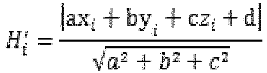
- The stereo camera according to claim 10, the ground image includes a plurality of contiguous ground images captured by the stereo camera; and
the first determining module is further configured to:perform median filtering in time domain on the plurality of contiguous ground images to obtain ground images after median filtering in time domain;perform median filtering in space domain on each ground image after median filtering in time domain to the ground images after median filtering in space domain; anddetermine depth information of each pixel on ground images after median filtering in space domain. - The stereo camera according to claim 10, where the acquiring module is further configured to:
acquire the angle information of the stereo camera by an angle sensor in the stereo camera. - The stereo camera according to claim 10, wherein the stereo camera is a binocular stereo camera or a time of flight (TOF) stereo camera.
- A stereo camera, comprising:at least one processing component; anda memory;Wherein the memory stores at least one program, configured to be executed by the at least one processing component, and configured to be executed by the at least one processing component to perform the method for acquiring a height of stereo camera as defined in any one of claims 1 to 9. stereo camera
- A height acquisition system, comprising: a remote control apparatus and a stereo camera; wherein the remote control apparatus is configured to remotely control the stereo camera; and
the stereo camera is the stereo camera as defined in any one of claims 10 to 19, or the stereo camera is the stereo camera as defined in claim 20. - A height acquisition system, comprising: a remote control apparatus and a stereo camera; wherein
the stereo camera is configured to:acquire angle information of the stereo camera, wherein the angle information includes a pitch angle and a tilt angle;capture a ground image of a scenario where the stereo camera is deployed; andsend the angle information and the ground image to the remote control apparatus;the remote control apparatus is configured to:receive the angle information and the ground image;determine depth information of each pixel on the ground image;establish a three-dimensional point set based on depth information of each pixel on the ground image, wherein the three-dimensional point set includes coordinate information of each three-dimensional point corresponding to each pixel on the ground image; anddetermine the height of the stereo camera based on the angle information and the three-dimensional point set. - A non-volatile computer-readable storage medium, which stores code instructions; wherein the code instructions are executed by a processor to perform the height acquisition method of a stereo camera as defined in any one of claims 1 to 9.
Applications Claiming Priority (2)
| Application Number | Priority Date | Filing Date | Title |
|---|---|---|---|
| CN201710100940.1A CN108510540B (en) | 2017-02-23 | 2017-02-23 | Stereoscopic vision camera and height acquisition method thereof |
| PCT/CN2018/076571 WO2018153313A1 (en) | 2017-02-23 | 2018-02-12 | Stereoscopic camera and height acquisition method therefor and height acquisition system |
Publications (3)
| Publication Number | Publication Date |
|---|---|
| EP3588004A1 true EP3588004A1 (en) | 2020-01-01 |
| EP3588004A4 EP3588004A4 (en) | 2020-03-04 |
| EP3588004B1 EP3588004B1 (en) | 2023-08-16 |
Family
ID=63253058
Family Applications (1)
| Application Number | Title | Priority Date | Filing Date |
|---|---|---|---|
| EP18756576.7A Active EP3588004B1 (en) | 2017-02-23 | 2018-02-12 | Stereoscopic camera and height acquisition method therefor and height acquisition system |
Country Status (4)
| Country | Link |
|---|---|
| US (1) | US11024052B2 (en) |
| EP (1) | EP3588004B1 (en) |
| CN (1) | CN108510540B (en) |
| WO (1) | WO2018153313A1 (en) |
Families Citing this family (17)
| Publication number | Priority date | Publication date | Assignee | Title |
|---|---|---|---|---|
| KR101995344B1 (en) * | 2019-01-22 | 2019-07-02 | 김흥수 | A dual depth camera module without blind spot |
| CN109945785A (en) * | 2019-03-26 | 2019-06-28 | 湖南安华鼎科技有限公司 | A kind of platform inclination angle and height method for real-time measurement and system |
| TWI720447B (en) * | 2019-03-28 | 2021-03-01 | 財團法人工業技術研究院 | Image positioning method and system thereof |
| CN110209001B (en) * | 2019-06-04 | 2024-06-14 | 上海亦我信息技术有限公司 | A tripod for 3D modeling and camera shooting posture recognition method |
| CN110490943B (en) * | 2019-08-26 | 2022-04-15 | 深圳市自由视像科技有限公司 | Rapid and accurate calibration method and system of 4D holographic capture system and storage medium |
| CN112449100B (en) * | 2019-09-03 | 2023-11-17 | 中国科学院长春光学精密机械与物理研究所 | Stitching method, device, terminal and storage medium for aerial camera oblique images |
| CN111273701B (en) * | 2020-02-28 | 2023-10-31 | 佛山科学技术学院 | A pan-tilt visual control system and control method |
| CN111415420B (en) * | 2020-03-25 | 2024-01-23 | 北京迈格威科技有限公司 | Spatial information determination method, device and electronic equipment |
| CN111462317B (en) * | 2020-04-27 | 2022-06-21 | 清华大学 | Camera arrangement method for monitoring space grid structure based on multi-view three-dimensional reconstruction |
| CN112541951A (en) * | 2020-11-13 | 2021-03-23 | 国网浙江省电力有限公司舟山供电公司 | Monitoring system and monitoring method for preventing ship from hooking off cross-sea overhead power line |
| CN112634152B (en) * | 2020-12-16 | 2024-06-18 | 中科海微(北京)科技有限公司 | Face sample data enhancement method and system based on image depth information |
| CN114066981A (en) * | 2021-11-11 | 2022-02-18 | 国网辽宁省电力有限公司沈阳供电公司 | Unmanned aerial vehicle ground target positioning method |
| CN115423840B (en) * | 2022-09-02 | 2026-03-03 | 安徽工业大学 | High-speed personnel entry and exit counting method based on depth camera |
| US12455381B2 (en) | 2022-10-05 | 2025-10-28 | Cisco Technology, Inc. | Deployment of time of flight sensor on camera |
| US12412307B2 (en) * | 2022-11-23 | 2025-09-09 | Tyco Fire & Security Gmbh | Camera calibration and distance measurement based on homography |
| CN116258773B (en) * | 2022-12-22 | 2026-03-27 | 上海汽车工业(集团)有限公司 | Methods, devices, equipment, and computer storage media for determining the camera's pitch angle |
| US12462586B2 (en) | 2023-07-10 | 2025-11-04 | Nvidia Corporation | Occupant evaluation using multi-modal sensor fusion for in-cabin monitoring systems and applications |
Family Cites Families (17)
| Publication number | Priority date | Publication date | Assignee | Title |
|---|---|---|---|---|
| US8855405B2 (en) * | 2003-04-30 | 2014-10-07 | Deere & Company | System and method for detecting and analyzing features in an agricultural field for vehicle guidance |
| US7068815B2 (en) * | 2003-06-13 | 2006-06-27 | Sarnoff Corporation | Method and apparatus for ground detection and removal in vision systems |
| WO2004114063A2 (en) * | 2003-06-13 | 2004-12-29 | Georgia Tech Research Corporation | Data reconstruction using directional interpolation techniques |
| US8289321B2 (en) * | 2004-03-17 | 2012-10-16 | Sony Corporation | Method and apparatus for detecting plane, and robot apparatus having apparatus for detecting plane |
| US20120004792A1 (en) * | 2007-09-28 | 2012-01-05 | The United States Of America As Represented By The Secretary Of The Navy | Weber-box, an aviation display device to support spatial awareness |
| US8542907B2 (en) * | 2007-12-17 | 2013-09-24 | Sony Computer Entertainment America Llc | Dynamic three-dimensional object mapping for user-defined control device |
| US10354407B2 (en) * | 2013-03-15 | 2019-07-16 | Spatial Cam Llc | Camera for locating hidden objects |
| CN101504287B (en) * | 2009-01-22 | 2011-01-05 | 浙江大学 | Attitude Parameter Estimation Method for Unmanned Aerial Vehicle Autonomous Landing Based on Visual Information |
| JP5839971B2 (en) * | 2010-12-14 | 2016-01-06 | キヤノン株式会社 | Information processing apparatus, information processing method, and program |
| KR101758058B1 (en) * | 2011-01-20 | 2017-07-17 | 삼성전자주식회사 | Apparatus and method for estimating camera motion using depth information, augmented reality system |
| EP2615580B1 (en) * | 2012-01-13 | 2016-08-17 | Softkinetic Software | Automatic scene calibration |
| CN103258322A (en) * | 2012-11-01 | 2013-08-21 | 南京朋源电气有限公司 | Determining method of moving target height under different projection angles |
| CN103854008B (en) * | 2012-12-04 | 2019-10-18 | 株式会社理光 | Road surface detection method and device |
| WO2016064879A1 (en) * | 2014-10-20 | 2016-04-28 | Bae Systems Information And Electronic Systems Integration Inc. | Scene-based non-uniformity correction in focal plane arrays |
| CN105469386B (en) * | 2015-11-11 | 2018-08-07 | 浙江大华技术股份有限公司 | A kind of method and device of determining stereoscopic camera height and pitch angle |
| CN105346706B (en) | 2015-11-13 | 2018-09-04 | 深圳市道通智能航空技术有限公司 | Flight instruments, flight control system and method |
| CN107945234A (en) * | 2016-10-12 | 2018-04-20 | 杭州海康威视数字技术股份有限公司 | A kind of definite method and device of stereo camera external parameter |
-
2017
- 2017-02-23 CN CN201710100940.1A patent/CN108510540B/en active Active
-
2018
- 2018-02-12 WO PCT/CN2018/076571 patent/WO2018153313A1/en not_active Ceased
- 2018-02-12 EP EP18756576.7A patent/EP3588004B1/en active Active
-
2019
- 2019-08-22 US US16/548,721 patent/US11024052B2/en active Active
Also Published As
| Publication number | Publication date |
|---|---|
| WO2018153313A1 (en) | 2018-08-30 |
| CN108510540A (en) | 2018-09-07 |
| US20190378294A1 (en) | 2019-12-12 |
| CN108510540B (en) | 2020-02-07 |
| EP3588004B1 (en) | 2023-08-16 |
| US11024052B2 (en) | 2021-06-01 |
| EP3588004A4 (en) | 2020-03-04 |
Similar Documents
| Publication | Publication Date | Title |
|---|---|---|
| US11024052B2 (en) | Stereo camera and height acquisition method thereof and height acquisition system | |
| US20230027389A1 (en) | Distance determination method, apparatus and system | |
| CN110427917B (en) | Method and device for detecting key points | |
| CN111383285B (en) | Sensor fusion calibration method and system based on millimeter wave radar and camera | |
| CN111028205B (en) | Eye pupil positioning method and device based on binocular distance measurement | |
| EP3389268B1 (en) | Depth information acquisition method and apparatus, and image collection device | |
| CN109640066B (en) | Method and device for generating high-precision dense depth images | |
| CN109472829B (en) | Object positioning method, device, equipment and storage medium | |
| CN111179329B (en) | Three-dimensional target detection method, device and electronic equipment | |
| EP3252715A1 (en) | Two-camera relative position calculation system, device and apparatus | |
| US20160042515A1 (en) | Method and device for camera calibration | |
| US10375378B2 (en) | Dual camera system for real-time depth map generation | |
| CN107084680B (en) | Target depth measuring method based on machine monocular vision | |
| CN111970454B (en) | Shot picture display method, device, equipment and storage medium | |
| CN116704048B (en) | Double-light registration method | |
| JPWO2011125937A1 (en) | Calibration data selection device, selection method, selection program, and three-dimensional position measurement device | |
| EP3499184A1 (en) | Measurement method and apparatus | |
| CN115187652A (en) | A body image-based height measurement method and device | |
| EP3026631A1 (en) | Method and apparatus for estimating depth of focused plenoptic data | |
| CN108282650B (en) | Naked eye three-dimensional display method, device and system and storage medium | |
| CN206583440U (en) | A kind of projected image sighting distance detecting system | |
| CN112017138B (en) | Image splicing method based on scene three-dimensional structure | |
| CN114549627A (en) | Method and device for measuring distance of target, image acquisition equipment and medium | |
| CN111080689B (en) | Method and apparatus for determining facial depth map | |
| KR20220080946A (en) | A method of measuring the size of an object of interest using a camera device |
Legal Events
| Date | Code | Title | Description |
|---|---|---|---|
| STAA | Information on the status of an ep patent application or granted ep patent |
Free format text: STATUS: THE INTERNATIONAL PUBLICATION HAS BEEN MADE |
|
| PUAI | Public reference made under article 153(3) epc to a published international application that has entered the european phase |
Free format text: ORIGINAL CODE: 0009012 |
|
| STAA | Information on the status of an ep patent application or granted ep patent |
Free format text: STATUS: REQUEST FOR EXAMINATION WAS MADE |
|
| 17P | Request for examination filed |
Effective date: 20190923 |
|
| AK | Designated contracting states |
Kind code of ref document: A1 Designated state(s): AL AT BE BG CH CY CZ DE DK EE ES FI FR GB GR HR HU IE IS IT LI LT LU LV MC MK MT NL NO PL PT RO RS SE SI SK SM TR |
|
| AX | Request for extension of the european patent |
Extension state: BA ME |
|
| REG | Reference to a national code |
Ref country code: DE Ref legal event code: R079 Free format text: PREVIOUS MAIN CLASS: G01C0021200000 Ipc: G06T0007800000 Ref document number: 602018055490 Country of ref document: DE |
|
| A4 | Supplementary search report drawn up and despatched |
Effective date: 20200203 |
|
| RIC1 | Information provided on ipc code assigned before grant |
Ipc: G06T 7/80 20170101AFI20200128BHEP |
|
| DAV | Request for validation of the european patent (deleted) | ||
| DAX | Request for extension of the european patent (deleted) | ||
| STAA | Information on the status of an ep patent application or granted ep patent |
Free format text: STATUS: EXAMINATION IS IN PROGRESS |
|
| 17Q | First examination report despatched |
Effective date: 20210118 |
|
| GRAP | Despatch of communication of intention to grant a patent |
Free format text: ORIGINAL CODE: EPIDOSNIGR1 |
|
| STAA | Information on the status of an ep patent application or granted ep patent |
Free format text: STATUS: GRANT OF PATENT IS INTENDED |
|
| INTG | Intention to grant announced |
Effective date: 20230412 |
|
| GRAS | Grant fee paid |
Free format text: ORIGINAL CODE: EPIDOSNIGR3 |
|
| GRAA | (expected) grant |
Free format text: ORIGINAL CODE: 0009210 |
|
| STAA | Information on the status of an ep patent application or granted ep patent |
Free format text: STATUS: THE PATENT HAS BEEN GRANTED |
|
| P01 | Opt-out of the competence of the unified patent court (upc) registered |
Effective date: 20230627 |
|
| AK | Designated contracting states |
Kind code of ref document: B1 Designated state(s): AL AT BE BG CH CY CZ DE DK EE ES FI FR GB GR HR HU IE IS IT LI LT LU LV MC MK MT NL NO PL PT RO RS SE SI SK SM TR |
|
| REG | Reference to a national code |
Ref country code: CH Ref legal event code: EP |
|
| REG | Reference to a national code |
Ref country code: DE Ref legal event code: R096 Ref document number: 602018055490 Country of ref document: DE |
|
| REG | Reference to a national code |
Ref country code: IE Ref legal event code: FG4D |
|
| REG | Reference to a national code |
Ref country code: LT Ref legal event code: MG9D |
|
| REG | Reference to a national code |
Ref country code: NL Ref legal event code: MP Effective date: 20230816 |
|
| REG | Reference to a national code |
Ref country code: AT Ref legal event code: MK05 Ref document number: 1600821 Country of ref document: AT Kind code of ref document: T Effective date: 20230816 |
|
| PG25 | Lapsed in a contracting state [announced via postgrant information from national office to epo] |
Ref country code: GR Free format text: LAPSE BECAUSE OF FAILURE TO SUBMIT A TRANSLATION OF THE DESCRIPTION OR TO PAY THE FEE WITHIN THE PRESCRIBED TIME-LIMIT Effective date: 20231117 |
|
| PG25 | Lapsed in a contracting state [announced via postgrant information from national office to epo] |
Ref country code: IS Free format text: LAPSE BECAUSE OF FAILURE TO SUBMIT A TRANSLATION OF THE DESCRIPTION OR TO PAY THE FEE WITHIN THE PRESCRIBED TIME-LIMIT Effective date: 20231216 |
|
| PG25 | Lapsed in a contracting state [announced via postgrant information from national office to epo] |
Ref country code: SE Free format text: LAPSE BECAUSE OF FAILURE TO SUBMIT A TRANSLATION OF THE DESCRIPTION OR TO PAY THE FEE WITHIN THE PRESCRIBED TIME-LIMIT Effective date: 20230816 Ref country code: RS Free format text: LAPSE BECAUSE OF FAILURE TO SUBMIT A TRANSLATION OF THE DESCRIPTION OR TO PAY THE FEE WITHIN THE PRESCRIBED TIME-LIMIT Effective date: 20230816 Ref country code: PT Free format text: LAPSE BECAUSE OF FAILURE TO SUBMIT A TRANSLATION OF THE DESCRIPTION OR TO PAY THE FEE WITHIN THE PRESCRIBED TIME-LIMIT Effective date: 20231218 Ref country code: NO Free format text: LAPSE BECAUSE OF FAILURE TO SUBMIT A TRANSLATION OF THE DESCRIPTION OR TO PAY THE FEE WITHIN THE PRESCRIBED TIME-LIMIT Effective date: 20231116 Ref country code: NL Free format text: LAPSE BECAUSE OF FAILURE TO SUBMIT A TRANSLATION OF THE DESCRIPTION OR TO PAY THE FEE WITHIN THE PRESCRIBED TIME-LIMIT Effective date: 20230816 Ref country code: LV Free format text: LAPSE BECAUSE OF FAILURE TO SUBMIT A TRANSLATION OF THE DESCRIPTION OR TO PAY THE FEE WITHIN THE PRESCRIBED TIME-LIMIT Effective date: 20230816 Ref country code: LT Free format text: LAPSE BECAUSE OF FAILURE TO SUBMIT A TRANSLATION OF THE DESCRIPTION OR TO PAY THE FEE WITHIN THE PRESCRIBED TIME-LIMIT Effective date: 20230816 Ref country code: IS Free format text: LAPSE BECAUSE OF FAILURE TO SUBMIT A TRANSLATION OF THE DESCRIPTION OR TO PAY THE FEE WITHIN THE PRESCRIBED TIME-LIMIT Effective date: 20231216 Ref country code: HR Free format text: LAPSE BECAUSE OF FAILURE TO SUBMIT A TRANSLATION OF THE DESCRIPTION OR TO PAY THE FEE WITHIN THE PRESCRIBED TIME-LIMIT Effective date: 20230816 Ref country code: GR Free format text: LAPSE BECAUSE OF FAILURE TO SUBMIT A TRANSLATION OF THE DESCRIPTION OR TO PAY THE FEE WITHIN THE PRESCRIBED TIME-LIMIT Effective date: 20231117 Ref country code: FI Free format text: LAPSE BECAUSE OF FAILURE TO SUBMIT A TRANSLATION OF THE DESCRIPTION OR TO PAY THE FEE WITHIN THE PRESCRIBED TIME-LIMIT Effective date: 20230816 Ref country code: AT Free format text: LAPSE BECAUSE OF FAILURE TO SUBMIT A TRANSLATION OF THE DESCRIPTION OR TO PAY THE FEE WITHIN THE PRESCRIBED TIME-LIMIT Effective date: 20230816 |
|
| PG25 | Lapsed in a contracting state [announced via postgrant information from national office to epo] |
Ref country code: PL Free format text: LAPSE BECAUSE OF FAILURE TO SUBMIT A TRANSLATION OF THE DESCRIPTION OR TO PAY THE FEE WITHIN THE PRESCRIBED TIME-LIMIT Effective date: 20230816 |
|
| PG25 | Lapsed in a contracting state [announced via postgrant information from national office to epo] |
Ref country code: ES Free format text: LAPSE BECAUSE OF FAILURE TO SUBMIT A TRANSLATION OF THE DESCRIPTION OR TO PAY THE FEE WITHIN THE PRESCRIBED TIME-LIMIT Effective date: 20230816 |
|
| PG25 | Lapsed in a contracting state [announced via postgrant information from national office to epo] |
Ref country code: SM Free format text: LAPSE BECAUSE OF FAILURE TO SUBMIT A TRANSLATION OF THE DESCRIPTION OR TO PAY THE FEE WITHIN THE PRESCRIBED TIME-LIMIT Effective date: 20230816 Ref country code: RO Free format text: LAPSE BECAUSE OF FAILURE TO SUBMIT A TRANSLATION OF THE DESCRIPTION OR TO PAY THE FEE WITHIN THE PRESCRIBED TIME-LIMIT Effective date: 20230816 Ref country code: ES Free format text: LAPSE BECAUSE OF FAILURE TO SUBMIT A TRANSLATION OF THE DESCRIPTION OR TO PAY THE FEE WITHIN THE PRESCRIBED TIME-LIMIT Effective date: 20230816 Ref country code: EE Free format text: LAPSE BECAUSE OF FAILURE TO SUBMIT A TRANSLATION OF THE DESCRIPTION OR TO PAY THE FEE WITHIN THE PRESCRIBED TIME-LIMIT Effective date: 20230816 Ref country code: DK Free format text: LAPSE BECAUSE OF FAILURE TO SUBMIT A TRANSLATION OF THE DESCRIPTION OR TO PAY THE FEE WITHIN THE PRESCRIBED TIME-LIMIT Effective date: 20230816 Ref country code: CZ Free format text: LAPSE BECAUSE OF FAILURE TO SUBMIT A TRANSLATION OF THE DESCRIPTION OR TO PAY THE FEE WITHIN THE PRESCRIBED TIME-LIMIT Effective date: 20230816 Ref country code: SK Free format text: LAPSE BECAUSE OF FAILURE TO SUBMIT A TRANSLATION OF THE DESCRIPTION OR TO PAY THE FEE WITHIN THE PRESCRIBED TIME-LIMIT Effective date: 20230816 |
|
| REG | Reference to a national code |
Ref country code: DE Ref legal event code: R097 Ref document number: 602018055490 Country of ref document: DE |
|
| PLBE | No opposition filed within time limit |
Free format text: ORIGINAL CODE: 0009261 |
|
| STAA | Information on the status of an ep patent application or granted ep patent |
Free format text: STATUS: NO OPPOSITION FILED WITHIN TIME LIMIT |
|
| 26N | No opposition filed |
Effective date: 20240517 |
|
| PG25 | Lapsed in a contracting state [announced via postgrant information from national office to epo] |
Ref country code: IT Free format text: LAPSE BECAUSE OF FAILURE TO SUBMIT A TRANSLATION OF THE DESCRIPTION OR TO PAY THE FEE WITHIN THE PRESCRIBED TIME-LIMIT Effective date: 20230816 Ref country code: SI Free format text: LAPSE BECAUSE OF FAILURE TO SUBMIT A TRANSLATION OF THE DESCRIPTION OR TO PAY THE FEE WITHIN THE PRESCRIBED TIME-LIMIT Effective date: 20230816 |
|
| PG25 | Lapsed in a contracting state [announced via postgrant information from national office to epo] |
Ref country code: MC Free format text: LAPSE BECAUSE OF FAILURE TO SUBMIT A TRANSLATION OF THE DESCRIPTION OR TO PAY THE FEE WITHIN THE PRESCRIBED TIME-LIMIT Effective date: 20230816 |
|
| REG | Reference to a national code |
Ref country code: CH Ref legal event code: PL |
|
| PG25 | Lapsed in a contracting state [announced via postgrant information from national office to epo] |
Ref country code: LU Free format text: LAPSE BECAUSE OF NON-PAYMENT OF DUE FEES Effective date: 20240212 |
|
| PG25 | Lapsed in a contracting state [announced via postgrant information from national office to epo] |
Ref country code: CH Free format text: LAPSE BECAUSE OF NON-PAYMENT OF DUE FEES Effective date: 20240229 |
|
| PG25 | Lapsed in a contracting state [announced via postgrant information from national office to epo] |
Ref country code: LU Free format text: LAPSE BECAUSE OF NON-PAYMENT OF DUE FEES Effective date: 20240212 Ref country code: CH Free format text: LAPSE BECAUSE OF NON-PAYMENT OF DUE FEES Effective date: 20240229 |
|
| PG25 | Lapsed in a contracting state [announced via postgrant information from national office to epo] |
Ref country code: BG Free format text: LAPSE BECAUSE OF FAILURE TO SUBMIT A TRANSLATION OF THE DESCRIPTION OR TO PAY THE FEE WITHIN THE PRESCRIBED TIME-LIMIT Effective date: 20230816 |
|
| PG25 | Lapsed in a contracting state [announced via postgrant information from national office to epo] |
Ref country code: BG Free format text: LAPSE BECAUSE OF FAILURE TO SUBMIT A TRANSLATION OF THE DESCRIPTION OR TO PAY THE FEE WITHIN THE PRESCRIBED TIME-LIMIT Effective date: 20230816 |
|
| REG | Reference to a national code |
Ref country code: BE Ref legal event code: MM Effective date: 20240229 |
|
| PG25 | Lapsed in a contracting state [announced via postgrant information from national office to epo] |
Ref country code: BE Free format text: LAPSE BECAUSE OF NON-PAYMENT OF DUE FEES Effective date: 20240229 |
|
| PG25 | Lapsed in a contracting state [announced via postgrant information from national office to epo] |
Ref country code: IE Free format text: LAPSE BECAUSE OF NON-PAYMENT OF DUE FEES Effective date: 20240212 |
|
| PG25 | Lapsed in a contracting state [announced via postgrant information from national office to epo] |
Ref country code: IE Free format text: LAPSE BECAUSE OF NON-PAYMENT OF DUE FEES Effective date: 20240212 Ref country code: BE Free format text: LAPSE BECAUSE OF NON-PAYMENT OF DUE FEES Effective date: 20240229 |
|
| PG25 | Lapsed in a contracting state [announced via postgrant information from national office to epo] |
Ref country code: CY Free format text: LAPSE BECAUSE OF FAILURE TO SUBMIT A TRANSLATION OF THE DESCRIPTION OR TO PAY THE FEE WITHIN THE PRESCRIBED TIME-LIMIT; INVALID AB INITIO Effective date: 20180212 |
|
| PG25 | Lapsed in a contracting state [announced via postgrant information from national office to epo] |
Ref country code: HU Free format text: LAPSE BECAUSE OF FAILURE TO SUBMIT A TRANSLATION OF THE DESCRIPTION OR TO PAY THE FEE WITHIN THE PRESCRIBED TIME-LIMIT; INVALID AB INITIO Effective date: 20180212 |
|
| PG25 | Lapsed in a contracting state [announced via postgrant information from national office to epo] |
Ref country code: TR Free format text: LAPSE BECAUSE OF FAILURE TO SUBMIT A TRANSLATION OF THE DESCRIPTION OR TO PAY THE FEE WITHIN THE PRESCRIBED TIME-LIMIT Effective date: 20230816 |
|
| PGFP | Annual fee paid to national office [announced via postgrant information from national office to epo] |
Ref country code: GB Payment date: 20260219 Year of fee payment: 9 |
|
| PGFP | Annual fee paid to national office [announced via postgrant information from national office to epo] |
Ref country code: DE Payment date: 20260206 Year of fee payment: 9 |
|
| PGFP | Annual fee paid to national office [announced via postgrant information from national office to epo] |
Ref country code: FR Payment date: 20260227 Year of fee payment: 9 |