EP3587999A1 - Measuring device and fabricating apparatus - Google Patents
Measuring device and fabricating apparatus Download PDFInfo
- Publication number
- EP3587999A1 EP3587999A1 EP19182129.7A EP19182129A EP3587999A1 EP 3587999 A1 EP3587999 A1 EP 3587999A1 EP 19182129 A EP19182129 A EP 19182129A EP 3587999 A1 EP3587999 A1 EP 3587999A1
- Authority
- EP
- European Patent Office
- Prior art keywords
- data
- fabrication
- measurement
- dimensional
- fabricating
- Prior art date
- Legal status (The legal status is an assumption and is not a legal conclusion. Google has not performed a legal analysis and makes no representation as to the accuracy of the status listed.)
- Granted
Links
Images


Classifications
-
- G—PHYSICS
- G01—MEASURING; TESTING
- G01B—MEASURING LENGTH, THICKNESS OR SIMILAR LINEAR DIMENSIONS; MEASURING ANGLES; MEASURING AREAS; MEASURING IRREGULARITIES OF SURFACES OR CONTOURS
- G01B11/00—Measuring arrangements characterised by the use of optical techniques
- G01B11/24—Measuring arrangements characterised by the use of optical techniques for measuring contours or curvatures
- G01B11/25—Measuring arrangements characterised by the use of optical techniques for measuring contours or curvatures by projecting a pattern, e.g. one or more lines, moiré fringes on the object
- G01B11/2518—Projection by scanning of the object
-
- G—PHYSICS
- G01—MEASURING; TESTING
- G01B—MEASURING LENGTH, THICKNESS OR SIMILAR LINEAR DIMENSIONS; MEASURING ANGLES; MEASURING AREAS; MEASURING IRREGULARITIES OF SURFACES OR CONTOURS
- G01B11/00—Measuring arrangements characterised by the use of optical techniques
- G01B11/24—Measuring arrangements characterised by the use of optical techniques for measuring contours or curvatures
- G01B11/25—Measuring arrangements characterised by the use of optical techniques for measuring contours or curvatures by projecting a pattern, e.g. one or more lines, moiré fringes on the object
- G01B11/254—Projection of a pattern, viewing through a pattern, e.g. moiré
-
- B—PERFORMING OPERATIONS; TRANSPORTING
- B29—WORKING OF PLASTICS; WORKING OF SUBSTANCES IN A PLASTIC STATE IN GENERAL
- B29C—SHAPING OR JOINING OF PLASTICS; SHAPING OF MATERIAL IN A PLASTIC STATE, NOT OTHERWISE PROVIDED FOR; AFTER-TREATMENT OF THE SHAPED PRODUCTS, e.g. REPAIRING
- B29C64/00—Additive manufacturing, i.e. manufacturing of three-dimensional [3D] objects by additive deposition, additive agglomeration or additive layering, e.g. by 3D printing, stereolithography or selective laser sintering
- B29C64/30—Auxiliary operations or equipment
- B29C64/386—Data acquisition or data processing for additive manufacturing
- B29C64/393—Data acquisition or data processing for additive manufacturing for controlling or regulating additive manufacturing processes
-
- B—PERFORMING OPERATIONS; TRANSPORTING
- B33—ADDITIVE MANUFACTURING TECHNOLOGY
- B33Y—ADDITIVE MANUFACTURING, i.e. MANUFACTURING OF THREE-DIMENSIONAL [3D] OBJECTS BY ADDITIVE DEPOSITION, ADDITIVE AGGLOMERATION OR ADDITIVE LAYERING, e.g. BY 3D PRINTING, STEREOLITHOGRAPHY OR SELECTIVE LASER SINTERING
- B33Y50/00—Data acquisition or data processing for additive manufacturing
- B33Y50/02—Data acquisition or data processing for additive manufacturing for controlling or regulating additive manufacturing processes
-
- G—PHYSICS
- G05—CONTROLLING; REGULATING
- G05B—CONTROL OR REGULATING SYSTEMS IN GENERAL; FUNCTIONAL ELEMENTS OF SUCH SYSTEMS; MONITORING OR TESTING ARRANGEMENTS FOR SUCH SYSTEMS OR ELEMENTS
- G05B19/00—Program-control systems
- G05B19/02—Program-control systems electric
- G05B19/18—Numerical control [NC], i.e. automatically operating machines, in particular machine tools, e.g. in a manufacturing environment, so as to execute positioning, movement or co-ordinated operations by means of program data in numerical form
- G05B19/4097—Numerical control [NC], i.e. automatically operating machines, in particular machine tools, e.g. in a manufacturing environment, so as to execute positioning, movement or co-ordinated operations by means of program data in numerical form characterised by using design data to control NC machines, e.g. CAD/CAM
- G05B19/4099—Surface or curve machining, making three-dimensional [3D] objects, e.g. desktop manufacturing
-
- G—PHYSICS
- G06—COMPUTING OR CALCULATING; COUNTING
- G06T—IMAGE DATA PROCESSING OR GENERATION, IN GENERAL
- G06T7/00—Image analysis
- G06T7/50—Depth or shape recovery
- G06T7/521—Depth or shape recovery from laser ranging, e.g. using interferometry; from the projection of structured light
-
- G—PHYSICS
- G05—CONTROLLING; REGULATING
- G05B—CONTROL OR REGULATING SYSTEMS IN GENERAL; FUNCTIONAL ELEMENTS OF SUCH SYSTEMS; MONITORING OR TESTING ARRANGEMENTS FOR SUCH SYSTEMS OR ELEMENTS
- G05B2219/00—Program-control systems
- G05B2219/30—Nc systems
- G05B2219/49—Nc machine tool, till multiple
- G05B2219/49023—3-D printing, layer of powder, add drops of binder in layer, new powder
Definitions
- a technology is known that sets the spatial resolution of a measurement point adaptively to each local region to shorten the measurement processing time in the scanning of the three-dimensional shape of a measurement object to be a target of three-dimensional fabrication by a fabricating apparatus (see JP2012-194061-A ).
- the present invention is made in light of the above-described situation, and an object of the present invention is to inexpensively and easily achieve the precision of three-dimensional data of a three-dimensional object or a formation intermediate object.
- a measuring device that includes a measurement data acquisition unit, a predicting unit, and a calculation unit.
- the measurement data acquisition unit projects a pattern light beam onto a measurement object and acquire, as measurement data, a projection image of the measurement object onto which the pattern light beam is projected.
- the predicting unit predicts, using fabrication data for fabricating the measurement object, a probable image formed by projection of the pattern light beam onto the measurement object to form prediction data.
- the calculation unit corrects the measurement data with the prediction data to form corrected data, and calculate three-dimensional data to the measurement object, using the corrected data.
- a fabricating apparatus that includes a fabricating device, the measuring device, and a control unit.
- the fabricating device fabricates a three-dimensional object according to fabrication data.
- the measuring device measures the three-dimensional object as the measurement object.
- the control unit controls the fabrication device based on the three-dimensional data measured by the measuring device.
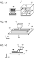
- FIGS. 1A, 1B, and 1C are schematic views of a configuration of a three-dimensional fabricating system 1 according to an embodiment of the present disclosure.
- the height direction of a three-dimensional object is referred to as z-axis direction
- a plane orthogonal to the z-axis direction is referred to as xy plane for convenience of explanation.
- the three-dimensional fabricating system 1 includes a fabricating apparatus 100 to fabricate a three-dimensional object and an information processing terminal 150.
- the information processing terminal 150 transmits, to the fabricating apparatus 100, shape data of a three-dimensional object to be fabricated.
- the fabricating apparatus 100 receives the shape data of the three-dimensional object to be fabricated, which is transmitted from the information processing terminal 150.
- the fabricating apparatus 100 forms a three-dimensional object based on the shape data.
- the information processing terminal 150 may operate as a controller that controls a process executed by the fabricating apparatus 100.
- the fabricating apparatus 100 may incorporate a function of the information processing terminal 150.
- the fabricating apparatus 100 includes a head 110 and a stage 120.
- the head 110 is movable in parallel to the xy plane.
- the fabricating apparatus 100 discharges a fabrication material 140 from the head 110 onto the stage 120 and fabricates a layer shape on the xy plane.
- the fabricating apparatus 100 draws one-dimensional line drawing in the same plane to fabricate a fabrication layer corresponding to one layer of a three-dimensional object.
- the fabricating apparatus 100 When the fabrication of a first fabrication layer is completed, the fabricating apparatus 100 lowers the stage 120 by the height (lamination pitch) of one layer in the direction along the z-axis. The fabricating apparatus 100 drives the head 110 in the same manner as for the first layer to form a second fabrication layer. The fabricating apparatus 100 repeats the above-described operations to laminate fabrication layers and fabricate the three-dimensional object.
- the fabricating apparatus 100 is described with an example of the configuration of moving the head 110 in the xy plane and moving the stage 120 in the z-axis direction.
- the configuration of the fabricating apparatus 100 is not limited to the above-described configuration in the present embodiment but may be any other suitable configuration.
- the fabricating apparatus 100 further includes a shape sensor 130 to measure the shape of a fabrication layer during fabrication or the shape of a three-dimensional object after fabrication.
- the shape sensor 130 measures, for example, the dimensions in the x-axis, y-axis, and z-axis directions of a three-dimensional object.
- the shape sensor 130 examples include an infrared sensor, a camera, and a three-dimensional measurement sensor (for example, a light-cutting profile sensor). That is, the fabricating apparatus 100 also functions as a reading device or a measuring device.
- a three-dimensional (3D) measurement sensor (for example, a light cutting profile sensor) is applied as the shape sensor 130.
- the shape sensor 130 (3D measurement sensor) includes a projection unit 130a (see FIG. 4 ) to project a pattern light beam on a measurement object and a camera 130b to acquire image data of a two-dimensional (2D) image (camera image) of the measurement object onto which the pattern light beam is projected.
- the shape sensor 130 may measure the shape of a fabrication layer in conjunction with the fabricating operation by the head 110.
- the shape sensor 130 may also measure the shape of one fabrication layer each time the fabrication layer is fabricated. Further, the timing and range of the measurement of the three-dimensional object with the shape sensor 130 may be arbitrarily selected and are not particularly limited to the above-described embodiment.
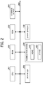
- FIG. 2 is a diagram of a hardware configuration of the fabricating apparatus 100.
- the fabricating apparatus 100 includes a central processing unit (CPU) 201, a random access memory (RAM) 202, a read only memory (ROM) 203, a storage device 204, an interface 205, a fabrication device 206, and the shape sensor 130.
- CPU central processing unit
- RAM random access memory
- ROM read only memory
- the CPU 201 is a device that executes a program that controls an operation of the fabricating apparatus 100 and performs predetermined processing.
- the RAM 202 is a volatile storage device to provide an execution space of a program executed by the CPU 201 and is used to store and expand programs and data.
- the ROM 203 is a nonvolatile storage device to store programs and firmware, etc., executed by the CPU 201.
- the storage device 204 is a readable and writable non-volatile storage device that stores an operation system (OS), various applications, programs, setting information, various data, and the like that cause the fabricating apparatus 100 to function.
- OS operation system
- various applications programs, setting information, various data, and the like that cause the fabricating apparatus 100 to function.
- the program (including the OS and various applications) executed by the fabricating apparatus 100 according to the present embodiment is a file of an installable format or an executable format, and is recorded and provided in a computer readable recording medium, such as a compact disc-read only memory (CD-ROM), a flexible disk (FD), a compact disc-recordable (CD-R), a digital versatile disk (DVD).
- a computer readable recording medium such as a compact disc-read only memory (CD-ROM), a flexible disk (FD), a compact disc-recordable (CD-R), a digital versatile disk (DVD).
- the program (including the OS and various applications) executed by the fabricating apparatus 100 according to the present embodiment may also be stored on a computer connected to a network such as the Internet, and provided by being downloaded via the network. Further, the program (including the OS and various applications) executed by the fabricating apparatus 100 according to the present embodiment may be provided or distributed via a network such as the Internet.
- the program (including the OS and various applications) executed by the fabricating apparatus 100 according to the present embodiment may be provided by being incorporated in advance in a ROM or the like.
- the interface 205 is a device to connect the fabricating apparatus 100 to another apparatus.
- the interface 205 can be connected to, for example, the information processing terminal 150, a network, an external storage device, or the like.
- the fabricating apparatus 100 can receive control data of a fabricating operation, shape data of a three-dimensional object, and the like via the interface 205.
- the fabrication device 206 is a fabricator that fabricates a desired three-dimensional object from the fabrication material 140.
- the fabrication device 206 includes the head 110, the stage 120, and the like, and is configured in accordance with a fabrication method.
- the fabrication device 206 in a fused filament fabrication (FFF) method includes a heating mechanism to melt the fabrication material 140, a nozzle to discharge the fabrication material 140, and so on.
- the fabrication device 206 in a selective laser sintering (SLS) method includes a laser light source and the like.
- the shape sensor 130 is a device that measures the shape of the fabrication layer during fabrication or the three-dimensional object after fabrication.
- the CPU 201 of the fabricating apparatus 100 includes a data input unit 310, a fabrication data generating unit 320, a fabrication-device control unit 330, an object shape measuring unit 340, a comparing unit 350, a correcting unit 360, a storing unit 370, a predicting unit 380, and a three-dimensional data calculation unit 390.
- the CPU 201 executes programs to achieve the above-described functions of the fabricating apparatus 100.
- embodiments of the present disclosure are not limited to such a configuration.
- a part or all the functions of the above-described units may be achieved by dedicated hardware circuits.
- the fabrication data generating unit 320 divides the shape data input to the data input unit 310 in the height direction of the three-dimensional object, to generate fabrication data of a plurality of fabrication layers.
- the three-dimensional object to be fabricated is divided into units of lamination pitch, and the fabrication data is generated as data indicating the shape of a fabrication layer to form each layer to be laminated.
- the fabrication data may be binary data indicating whether the fabrication process is executed or not in xy plane coordinates of each layer. In some embodiments, not only the presence or absence of fabrication at each coordinate but also the amount of fabrication at each coordinate, the discharge amount of the fabrication material, and the like may be included as parameters.
- the fabrication data generating unit 320 is included in the fabricating apparatus 100.
- the fabrication data generating unit 320 may be included in the information processing terminal 150. In such case, the fabrication data generated by the information processing terminal 150 is transmitted to the fabricating apparatus 100 to execute the fabrication process.
- the object shape measuring unit 340 acquires data for measuring the shape of the fabrication object. For example, when measuring the height data by the light cutting method, the object shape measuring unit 340 emits a line-shaped laser beam (pattern light beam) to a measurement target object, to acquire an image of reflected light with the camera 130b of the shape sensor 130. The object shape measuring unit 340 sends the acquired image data to the three-dimensional data calculation unit 390.
- a line-shaped laser beam pattern light beam
- the fabrication-device control unit 330 controls an operation of fabricating a three-dimensional object with the fabrication device 206 according to the fabrication data.
- the fabrication-device control unit 330 adjusts the position of the head 110 and the height of the stage 120 according to the fabrication data so that the fabrication-device control unit 330 can fabricate the three-dimensional object while controlling various parameters, such as the fabrication speed and the lamination pitch, and algorithms.
- the fabrication-device control unit 330 can also control the fabrication amount according to the fabrication data. For example, the discharge amount of the fabrication material 140 can be controlled in the FFF method, and the laser intensity can be controlled in the SLS method.
- the predicting unit 380 predicts a probable image to be obtained when the pattern light beam is projected onto the measurement object.
- the predicting unit 380 converts the certainty (probability) into gradations and combines the gradations into a probable image, and sends the probable image to the three-dimensional data calculation unit 390 as prediction data.
- the predicting unit 380 executes simulations of, for example, height variation of the measurement object, using the fabrication data for fabricating the measurement object (the formation layer in fabrication or the three-dimensional object after fabrication.
- FIGS. 4A to 4D are diagrams of an example of a method of generating prediction data in the predicting unit 380.
- a pattern light beam is emitted from the projection unit 130a of the shape sensor 130 (e.g., the 3D measurement sensor) to a measurement object (a fabrication layer during fabrication or a three-dimensional object after fabrication) having a step, to acquire a 2D image (camera image) with the camera 130b.
- the shape sensor 130 e.g., the 3D measurement sensor
- FIG. 4A illustrates a case in which the height Z of a measurement object in the z-axis direction is ideal.
- Emission line A in FIG. 4A represents an image obtained by imaging the ideal case in which the pattern light beam is emitted to a step b of the measurement object a with the camera 130b. That is, in the ideal case illustrated in FIG. 4A , a camera image can be obtained in which the emission line A is positioned on the step b of the measurement object a.
- the pattern light beam is emitted to a position closer to the projection unit 130a than the step b of the measurement object a.
- an emission line B is shifted to a position closer to the projection unit 130a than the emission line A as compared with in the ideal case illustrated in FIG. 4A .
- the pattern light beam is emitted to a position farther from the projection unit 130a than the step b of the measurement object a.
- an emission line C is shifted to a position farther from the projection unit 130a than the emission line A as compared with the ideal case illustrated in FIG. 4A .
- the predicting unit 380 executes simulation on the variation of the height Z as illustrated in FIGS. 4A to 4C , using fabrication data for fabricating the measurement object, to obtain a probable image.
- the emission line A, the emission line B, and the emission line C are weighted and displayed. That is, the emission line A in the ideal case is weighted more than each of the emission line B and the emission line C.
- Such a probable image illustrated in FIG. 4D is used as prediction data. That is, the predicting unit 380 converts the certainty into gradations and combines the gradations into a probable image as the prediction data.
- the three-dimensional data calculation unit 390 corrects the measurement data using the prediction data to obtain probable corrected measurement data.
- the three-dimensional data calculation unit 390 functions as a calculator and calculates three-dimensional data (actual height data) of the measurement object using the corrected measurement data.
- FIG. 5 is an illustration of a calculation method of three-dimensional data in the three-dimensional data calculation unit 390. As illustrated in FIG. 5 , the three-dimensional data calculation unit 390 corrects the measurement data using the prediction data to obtain probable corrected measurement data. The three-dimensional data calculation unit 390 calculates three-dimensional data (actual height data) of the measurement object using the corrected measurement data.
- the three-dimensional data calculation unit 390 uses prediction data for mask processing.
- the detection value of the measurement data coincident with the emission line A, the emission line B, or the emission line C of the prediction data has a higher occurrence probability as the weighting is larger.
- the measurement data contains many noise components. Therefore, the three-dimensional data calculation unit 390 masks the measurement data to remove a detected value with a low occurrence probability as noise and obtain corrected measurement data.
- the comparing unit 350 compares the fabrication data with the height data (three-dimensional data) calculated by the three-dimensional data calculation unit 390 and calculates an error caused by the fabrication, from a difference between the fabrication data and the height data.
- the shape of the three-dimensional object may vary with the type of the fabrication material 140 and various conditions such as the ambient temperature.
- the height data (three-dimensional data) used here refers to data obtained by measuring a plurality of fabrication layers fabricated in the first to nth layers and removing noise.
- shrinkage or warpage may occur as compared with immediately after forming. If the lamination is continued with shrinkage and the like, a three-dimensional object different from the desired three-dimensional object may be fabricated. Therefore, the error between the fabrication data and the height data (three-dimensional data) calculated by the three-dimensional data calculating unit 390, which indicates the shape of the fabrication layer actually fabricated, is fed back to the fabrication data of the subsequent layer and is used for correction.
- the correcting unit 360 corrects fabrication data for fabricating a three-dimensional object.
- the correcting unit 360 can correct the fabrication data so that the fabricating operation performed by the fabrication-device control unit 330 is changed according to the difference compared by the comparing unit 350.
- changing the fabricating operation indicates changing of parameters and algorithms included in the fabrication data. Examples of the parameters and algorithms include the shape of the three-dimensional object to be fabricated, the dimension and height of each fabrication layer, the fabrication amount based on the fabrication data, the melting temperature of the fabrication material, the fabrication speed, and the lamination pitch.
- the fabrication-device control unit 330 executes the fabrication process based on the corrected fabrication data.
- the storing unit 370 stores various data, such as shape data, fabrication data, measurement data, and height data (three-dimensional data) calculated by the three-dimensional data calculation unit 390, in the storage device 204. Various data are written into and read from the storing unit 370 by the functional units.
- FIG. 6 is a flowchart of a flow of processing in which the fabricating apparatus 100 fabricates a three-dimensional object.
- step S1 the data input unit 310 receives an input of shape data.
- step S2 the fabrication data generating unit 320 generates fabrication data in which the input shape data is divided into N layers in the height direction of the three-dimensional object.
- the generated fabrication data may be stored in the storing unit 370.
- step S4 the fabrication-device control unit 330 controls the operation of the fabrication device 206 according to the fabrication data of the nth layer to fabricate the fabrication layer of the nth layer.
- step S6 the object shape measuring unit 340 measures the shape of the nth fabrication layer fabricated.
- step S7 the three-dimensional data calculation unit 390 calculates three-dimensional data (actual height data) of the measurement object using the corrected measurement data obtained by correcting the measurement data using the prediction data.
- step S8 the comparing unit 350 compares the fabrication data of the nth layer with the three-dimensional data (actual height data) of the nth layer to calculate a difference.
- the correcting unit 360 corrects the fabrication data for fabricating the (n + 1)th layer according to the difference of the nth layer.
- the correction process may be performed for each layer or may be performed based on the difference between a plurality of layers.
- the difference between the layers may be stored in the storing unit 370 when needed, and the correcting unit 360 may read the difference between the layers stored in the storing unit 370 and correct the fabrication data of the (n + 1)th layer according to the difference from the first layer to the nth layer.
- step S10 the fabrication-device control unit 330 counts up the value of n to n + 1 and returns to the processing of step S4.
- step S4 executed at the second time and after, fabrication is performed based on the corrected fabrication data.
- the fabricating apparatus 100 repeats the process of steps S4 to S10 until the fabrication based on the fabrication data of the nth layer is completed.
- the fabricating operation can be changed by feeding back the difference based on the fabricated fabrication layer to the next fabrication layer by the process of the flowchart described above, thus allowing fabrication of a desired three-dimensional object.
- an image observed by the camera 130b is predicted using shape data of a measurement object (shape data for fabricating a three-dimensional object), and a camera image is corrected using the prediction data, and three-dimensional data (actual height data) of the measurement object is calculated using the corrected measurement data. Accordingly, in the case in which a prediction value of three-dimensional data of a measurement object can be calculated, the three-dimensional data (actual height data) of the measurement object can be inexpensively and easily obtained. In particular, a fabricating apparatus that fabricates a three-dimensional object can inexpensively and easily achieve high precision of three-dimensional data of an intermediate fabrication object.
- the present invention can be implemented in any convenient form, for example using dedicated hardware, or a mixture of dedicated hardware and software.
- the present invention may be implemented as computer software implemented by one or more networked processing apparatuses.
- the processing apparatuses can compromise any suitably programmed apparatuses such as a general purpose computer, personal digital assistant, mobile telephone (such as a WAP or 3G-compliant phone) and so on. Since the present invention can be implemented as software, each and every aspect of the present invention thus encompasses computer software implementable on a programmable device.
- the computer software can be provided to the programmable device using any conventional carrier medium (carrier means).
- the carrier medium can compromise a transient carrier medium such as an electrical, optical, microwave, acoustic or radio frequency signal carrying the computer code.
- transient medium is a TCP/IP signal carrying computer code over an IP network, such as the Internet.
- the carrier medium can also comprise a storage medium for storing processor readable code such as a floppy disk, hard disk, CD ROM, magnetic tape device or solid state memory device.
Landscapes
- Engineering & Computer Science (AREA)
- Materials Engineering (AREA)
- Chemical & Material Sciences (AREA)
- Physics & Mathematics (AREA)
- Manufacturing & Machinery (AREA)
- General Physics & Mathematics (AREA)
- Computer Vision & Pattern Recognition (AREA)
- Optics & Photonics (AREA)
- Mechanical Engineering (AREA)
- Human Computer Interaction (AREA)
- Automation & Control Theory (AREA)
- Theoretical Computer Science (AREA)
- Length Measuring Devices By Optical Means (AREA)
Abstract
Description
- Aspects of the present disclosure relate to a measuring device, a reading device, and a fabricating apparatus.
- A fabricating apparatus (so-called "3D printer") that fabricates a three-dimensional object based on input data has been developed. Various methods have been proposed to perform a three-dimensional fabrication, for example, a fused filament fabrication (FFF, a hotmelt filament manufacturing method), a selective laser sintering (SLS, a powder-sintering lamination fabrication method), a material jetting (MJ), an electron beam melting (EBM), and a stereolithography apparatus (SLA).
- For example, a technology is known that sets the spatial resolution of a measurement point adaptively to each local region to shorten the measurement processing time in the scanning of the three-dimensional shape of a measurement object to be a target of three-dimensional fabrication by a fabricating apparatus (see
JP2012-194061-A - To improve the accuracy of a conventional three-dimensional shape scanning, for example, it is conceivable to generate the pattern light to be irradiated to the measurement object with high resolution or to obtain an image irradiated with the pattern light at high resolution by a camera. However, even if the pattern light is generated at high resolution or the image irradiated with the pattern light is obtained at high resolution by the camera, generally, the amount of calculation would increase, thus increasing the cost to achieve the configuration.
- The present invention is made in light of the above-described situation, and an object of the present invention is to inexpensively and easily achieve the precision of three-dimensional data of a three-dimensional object or a formation intermediate object.
- In an aspect of the present disclosure, there is provided a measuring device that includes a measurement data acquisition unit, a predicting unit, and a calculation unit. The measurement data acquisition unit projects a pattern light beam onto a measurement object and acquire, as measurement data, a projection image of the measurement object onto which the pattern light beam is projected. The predicting unit predicts, using fabrication data for fabricating the measurement object, a probable image formed by projection of the pattern light beam onto the measurement object to form prediction data. The calculation unit corrects the measurement data with the prediction data to form corrected data, and calculate three-dimensional data to the measurement object, using the corrected data.
- In another aspect of the present disclosure, there is provided a fabricating apparatus that includes a fabricating device, the measuring device, and a control unit. The fabricating device fabricates a three-dimensional object according to fabrication data. The measuring device measures the three-dimensional object as the measurement object. The control unit controls the fabrication device based on the three-dimensional data measured by the measuring device.
- According to the present invention, there is an effect that the high precision of three-dimensional data of a three-dimensional object or a formation intermediate can be achieved inexpensively and easily.
- The aforementioned and other aspects, features, and advantages of the present disclosure would be better understood by reference to the following detailed description when considered in connection with the accompanying drawings, wherein:
-
FIGS. 1A, 1B, and 1C are schematic views of a configuration of a three-dimensional fabricating system according to an embodiment of the present disclosure; -
FIG. 2 is a schematic view of a hardware configuration of the fabricating apparatus; -
FIG. 3 is a block diagram of a functional configuration of the fabricating apparatus; -
FIGS. 4A, 4B ,4C, and 4D are diagrams of an example of a method of generating prediction data in a predicting unit; -
FIG. 5 is an illustration of a method of calculating three-dimensional data in a three-dimensional data calculation unit; and -
FIG. 6 is a flowchart of a flow of processing in which the fabricating apparatus fabricates a three-dimensional object. - The accompanying drawings are intended to depict embodiments of the present disclosure and should not be interpreted to limit the scope thereof. The accompanying drawings are not to be considered as drawn to scale unless explicitly noted.
- In describing embodiments illustrated in the drawings, specific terminology is employed for the sake of clarity. However, the disclosure of this patent specification is not intended to be limited to the specific terminology so selected and it is to be understood that each specific element includes all technical equivalents that operate in a similar manner and achieve similar results.
- Although the embodiments are described with technical limitations with reference to the attached drawings, such description is not intended to limit the scope of the disclosure and all of the components or elements described in the embodiments of this disclosure are not necessarily indispensable.
- Referring now to the drawings, embodiments of the present disclosure are described below. In the drawings for explaining the following embodiments, the same reference codes are allocated to elements (members or components) having the same function or shape and redundant descriptions thereof are omitted below.
- Hereinafter, embodiments of a reading device and a fabricating apparatus are described with reference to accompanying drawings.
-
FIGS. 1A, 1B, and 1C are schematic views of a configuration of a three-dimensional fabricating system 1 according to an embodiment of the present disclosure. In the following description, the height direction of a three-dimensional object is referred to as z-axis direction, and a plane orthogonal to the z-axis direction is referred to as xy plane for convenience of explanation. - As illustrated in
FIG.1A , the three-dimensional fabricating system 1 includes a fabricatingapparatus 100 to fabricate a three-dimensional object and aninformation processing terminal 150. Theinformation processing terminal 150 transmits, to the fabricatingapparatus 100, shape data of a three-dimensional object to be fabricated. The fabricatingapparatus 100 receives the shape data of the three-dimensional object to be fabricated, which is transmitted from theinformation processing terminal 150. The fabricatingapparatus 100 forms a three-dimensional object based on the shape data. - The
information processing terminal 150 may operate as a controller that controls a process executed by the fabricatingapparatus 100. The fabricatingapparatus 100 may incorporate a function of theinformation processing terminal 150. - As illustrated in
FIG. 1B , the fabricatingapparatus 100 includes ahead 110 and astage 120. Thehead 110 is movable in parallel to the xy plane. The fabricatingapparatus 100 discharges afabrication material 140 from thehead 110 onto thestage 120 and fabricates a layer shape on the xy plane. The fabricatingapparatus 100 draws one-dimensional line drawing in the same plane to fabricate a fabrication layer corresponding to one layer of a three-dimensional object. - When the fabrication of a first fabrication layer is completed, the fabricating
apparatus 100 lowers thestage 120 by the height (lamination pitch) of one layer in the direction along the z-axis. The fabricatingapparatus 100 drives thehead 110 in the same manner as for the first layer to form a second fabrication layer. The fabricatingapparatus 100 repeats the above-described operations to laminate fabrication layers and fabricate the three-dimensional object. - In the above description, the fabricating
apparatus 100 is described with an example of the configuration of moving thehead 110 in the xy plane and moving thestage 120 in the z-axis direction. However, the configuration of the fabricatingapparatus 100 is not limited to the above-described configuration in the present embodiment but may be any other suitable configuration. - As illustrated in
FIG. 1C , the fabricatingapparatus 100 further includes ashape sensor 130 to measure the shape of a fabrication layer during fabrication or the shape of a three-dimensional object after fabrication. Theshape sensor 130 measures, for example, the dimensions in the x-axis, y-axis, and z-axis directions of a three-dimensional object. - Examples of the
shape sensor 130 include an infrared sensor, a camera, and a three-dimensional measurement sensor (for example, a light-cutting profile sensor). That is, the fabricatingapparatus 100 also functions as a reading device or a measuring device. In the present embodiment, a three-dimensional (3D) measurement sensor (for example, a light cutting profile sensor) is applied as theshape sensor 130. The shape sensor 130 (3D measurement sensor) includes aprojection unit 130a (seeFIG. 4 ) to project a pattern light beam on a measurement object and acamera 130b to acquire image data of a two-dimensional (2D) image (camera image) of the measurement object onto which the pattern light beam is projected. - As illustrated in
FIG. 1C , for example, theshape sensor 130 may measure the shape of a fabrication layer in conjunction with the fabricating operation by thehead 110. Theshape sensor 130 may also measure the shape of one fabrication layer each time the fabrication layer is fabricated. Further, the timing and range of the measurement of the three-dimensional object with theshape sensor 130 may be arbitrarily selected and are not particularly limited to the above-described embodiment. - Next, a hardware configuration of the fabricating
apparatus 100 is described below. -
FIG. 2 is a diagram of a hardware configuration of the fabricatingapparatus 100. As illustrated inFIG. 2 , the fabricatingapparatus 100 includes a central processing unit (CPU) 201, a random access memory (RAM) 202, a read only memory (ROM) 203, astorage device 204, aninterface 205, afabrication device 206, and theshape sensor 130. Each piece of hardware is connected via abus 208. - The
CPU 201 is a device that executes a program that controls an operation of the fabricatingapparatus 100 and performs predetermined processing. TheRAM 202 is a volatile storage device to provide an execution space of a program executed by theCPU 201 and is used to store and expand programs and data. TheROM 203 is a nonvolatile storage device to store programs and firmware, etc., executed by theCPU 201. - The
storage device 204 is a readable and writable non-volatile storage device that stores an operation system (OS), various applications, programs, setting information, various data, and the like that cause the fabricatingapparatus 100 to function. - The program (including the OS and various applications) executed by the fabricating
apparatus 100 according to the present embodiment is a file of an installable format or an executable format, and is recorded and provided in a computer readable recording medium, such as a compact disc-read only memory (CD-ROM), a flexible disk (FD), a compact disc-recordable (CD-R), a digital versatile disk (DVD). - The program (including the OS and various applications) executed by the fabricating
apparatus 100 according to the present embodiment may also be stored on a computer connected to a network such as the Internet, and provided by being downloaded via the network. Further, the program (including the OS and various applications) executed by the fabricatingapparatus 100 according to the present embodiment may be provided or distributed via a network such as the Internet. - Further, the program (including the OS and various applications) executed by the fabricating
apparatus 100 according to the present embodiment may be provided by being incorporated in advance in a ROM or the like. - The
interface 205 is a device to connect the fabricatingapparatus 100 to another apparatus. Theinterface 205 can be connected to, for example, theinformation processing terminal 150, a network, an external storage device, or the like. The fabricatingapparatus 100 can receive control data of a fabricating operation, shape data of a three-dimensional object, and the like via theinterface 205. - The
fabrication device 206 is a fabricator that fabricates a desired three-dimensional object from thefabrication material 140. Thefabrication device 206 includes thehead 110, thestage 120, and the like, and is configured in accordance with a fabrication method. For example, thefabrication device 206 in a fused filament fabrication (FFF) method includes a heating mechanism to melt thefabrication material 140, a nozzle to discharge thefabrication material 140, and so on. Thefabrication device 206 in a selective laser sintering (SLS) method includes a laser light source and the like. - As described above, the
shape sensor 130 is a device that measures the shape of the fabrication layer during fabrication or the three-dimensional object after fabrication. - Next, a description is given of functions performed by the
CPU 201 of the fabricatingapparatus 100 executing programs stored in thestorage device 204 and theROM 203. -
FIG. 3 is a block diagram of a functional configuration of the fabricatingapparatus 100 according to an embodiment of the present disclosure. - As illustrated in
FIG. 3 , theCPU 201 of the fabricatingapparatus 100 includes adata input unit 310, a fabricationdata generating unit 320, a fabrication-device control unit 330, an objectshape measuring unit 340, a comparingunit 350, a correctingunit 360, astoring unit 370, a predictingunit 380, and a three-dimensionaldata calculation unit 390. - In the present embodiment, the
CPU 201 executes programs to achieve the above-described functions of the fabricatingapparatus 100. However, embodiments of the present disclosure are not limited to such a configuration. For example, a part or all the functions of the above-described units may be achieved by dedicated hardware circuits. - The
data input unit 310 receives input such as shape data to form a three-dimensional object. The shape data is generated by, for example, theinformation processing terminal 150 and is input to thedata input unit 310 via theinterface 205. - The fabrication
data generating unit 320 divides the shape data input to thedata input unit 310 in the height direction of the three-dimensional object, to generate fabrication data of a plurality of fabrication layers. The three-dimensional object to be fabricated is divided into units of lamination pitch, and the fabrication data is generated as data indicating the shape of a fabrication layer to form each layer to be laminated. The fabrication data may be binary data indicating whether the fabrication process is executed or not in xy plane coordinates of each layer. In some embodiments, not only the presence or absence of fabrication at each coordinate but also the amount of fabrication at each coordinate, the discharge amount of the fabrication material, and the like may be included as parameters. - In
FIG. 3 , the fabricationdata generating unit 320 is included in the fabricatingapparatus 100. In some embodiments, the fabricationdata generating unit 320 may be included in theinformation processing terminal 150. In such case, the fabrication data generated by theinformation processing terminal 150 is transmitted to the fabricatingapparatus 100 to execute the fabrication process. - The object
shape measuring unit 340 controls theshape sensor 130 and measures measurement data such as height data as the shape of a measurement target layer that is a fabrication layer being fabricated or a three-dimensional object having been fabricated. The objectshape measuring unit 340 functions as a measurement data acquisition unit and acquires measurement results as measurement data. - For example, the object
shape measuring unit 340 acquires data for measuring the shape of the fabrication object. For example, when measuring the height data by the light cutting method, the objectshape measuring unit 340 emits a line-shaped laser beam (pattern light beam) to a measurement target object, to acquire an image of reflected light with thecamera 130b of theshape sensor 130. The objectshape measuring unit 340 sends the acquired image data to the three-dimensionaldata calculation unit 390. - The fabrication-
device control unit 330 controls an operation of fabricating a three-dimensional object with thefabrication device 206 according to the fabrication data. The fabrication-device control unit 330 adjusts the position of thehead 110 and the height of thestage 120 according to the fabrication data so that the fabrication-device control unit 330 can fabricate the three-dimensional object while controlling various parameters, such as the fabrication speed and the lamination pitch, and algorithms. The fabrication-device control unit 330 can also control the fabrication amount according to the fabrication data. For example, the discharge amount of thefabrication material 140 can be controlled in the FFF method, and the laser intensity can be controlled in the SLS method. - Using the shape data of the measurement object (shape data for fabricating the three-dimensional object), the predicting
unit 380 predicts a probable image to be obtained when the pattern light beam is projected onto the measurement object. The predictingunit 380 converts the certainty (probability) into gradations and combines the gradations into a probable image, and sends the probable image to the three-dimensionaldata calculation unit 390 as prediction data. - Here, the predicting
unit 380 is further described. The predictingunit 380 executes simulations of, for example, height variation of the measurement object, using the fabrication data for fabricating the measurement object (the formation layer in fabrication or the three-dimensional object after fabrication. -
FIGS. 4A to 4D are diagrams of an example of a method of generating prediction data in the predictingunit 380. In an example illustrated inFIG. 4 , a pattern light beam is emitted from theprojection unit 130a of the shape sensor 130 (e.g., the 3D measurement sensor) to a measurement object (a fabrication layer during fabrication or a three-dimensional object after fabrication) having a step, to acquire a 2D image (camera image) with thecamera 130b. -
FIG. 4A illustrates a case in which the height Z of a measurement object in the z-axis direction is ideal. Emission line A inFIG. 4A represents an image obtained by imaging the ideal case in which the pattern light beam is emitted to a step b of the measurement object a with thecamera 130b. That is, in the ideal case illustrated inFIG. 4A , a camera image can be obtained in which the emission line A is positioned on the step b of the measurement object a. - On the other hand, when the height Z of the measurement object a in the z-axis direction is higher than the height Z in the ideal case, as illustrated in
FIG. 4B , the pattern light beam is emitted to a position closer to theprojection unit 130a than the step b of the measurement object a. In such a case, an emission line B is shifted to a position closer to theprojection unit 130a than the emission line A as compared with in the ideal case illustrated inFIG. 4A . - On the other hand, when the height Z of the measurement object a in the z-axis direction is lower than the height Z in the ideal case, as illustrated in
FIG. 4C , the pattern light beam is emitted to a position farther from theprojection unit 130a than the step b of the measurement object a. In such a case, an emission line C is shifted to a position farther from theprojection unit 130a than the emission line A as compared with the ideal case illustrated inFIG. 4A . - The predicting
unit 380 executes simulation on the variation of the height Z as illustrated inFIGS. 4A to 4C , using fabrication data for fabricating the measurement object, to obtain a probable image. In the probable image illustrated inFIG. 4D , the emission line A, the emission line B, and the emission line C are weighted and displayed. That is, the emission line A in the ideal case is weighted more than each of the emission line B and the emission line C. Such a probable image illustrated inFIG. 4D is used as prediction data. That is, the predictingunit 380 converts the certainty into gradations and combines the gradations into a probable image as the prediction data. - The three-dimensional
data calculation unit 390 corrects the measurement data using the prediction data to obtain probable corrected measurement data. The three-dimensionaldata calculation unit 390 functions as a calculator and calculates three-dimensional data (actual height data) of the measurement object using the corrected measurement data. - Next, the three-dimensional
data calculation unit 390 is further described. -
FIG. 5 is an illustration of a calculation method of three-dimensional data in the three-dimensionaldata calculation unit 390. As illustrated inFIG. 5 , the three-dimensionaldata calculation unit 390 corrects the measurement data using the prediction data to obtain probable corrected measurement data. The three-dimensionaldata calculation unit 390 calculates three-dimensional data (actual height data) of the measurement object using the corrected measurement data. - For example, the three-dimensional
data calculation unit 390 uses prediction data for mask processing. The detection value of the measurement data coincident with the emission line A, the emission line B, or the emission line C of the prediction data has a higher occurrence probability as the weighting is larger. The measurement data contains many noise components. Therefore, the three-dimensionaldata calculation unit 390 masks the measurement data to remove a detected value with a low occurrence probability as noise and obtain corrected measurement data. - The comparing
unit 350 compares the fabrication data with the height data (three-dimensional data) calculated by the three-dimensionaldata calculation unit 390 and calculates an error caused by the fabrication, from a difference between the fabrication data and the height data. The shape of the three-dimensional object may vary with the type of thefabrication material 140 and various conditions such as the ambient temperature. The height data (three-dimensional data) used here refers to data obtained by measuring a plurality of fabrication layers fabricated in the first to nth layers and removing noise. In addition, after thefabrication material 140 is cooled or hardened, shrinkage or warpage may occur as compared with immediately after forming. If the lamination is continued with shrinkage and the like, a three-dimensional object different from the desired three-dimensional object may be fabricated. Therefore, the error between the fabrication data and the height data (three-dimensional data) calculated by the three-dimensionaldata calculating unit 390, which indicates the shape of the fabrication layer actually fabricated, is fed back to the fabrication data of the subsequent layer and is used for correction. - The correcting
unit 360 corrects fabrication data for fabricating a three-dimensional object. For example, the correctingunit 360 can correct the fabrication data so that the fabricating operation performed by the fabrication-device control unit 330 is changed according to the difference compared by the comparingunit 350. Here, changing the fabricating operation indicates changing of parameters and algorithms included in the fabrication data. Examples of the parameters and algorithms include the shape of the three-dimensional object to be fabricated, the dimension and height of each fabrication layer, the fabrication amount based on the fabrication data, the melting temperature of the fabrication material, the fabrication speed, and the lamination pitch. When the fabrication data is corrected, the fabrication-device control unit 330 executes the fabrication process based on the corrected fabrication data. - The storing
unit 370 stores various data, such as shape data, fabrication data, measurement data, and height data (three-dimensional data) calculated by the three-dimensionaldata calculation unit 390, in thestorage device 204. Various data are written into and read from the storingunit 370 by the functional units. -
FIG. 6 is a flowchart of a flow of processing in which the fabricatingapparatus 100 fabricates a three-dimensional object. - First, in step S1, the
data input unit 310 receives an input of shape data. In step S2, the fabricationdata generating unit 320 generates fabrication data in which the input shape data is divided into N layers in the height direction of the three-dimensional object. The generated fabrication data may be stored in thestoring unit 370. - In step S3, the fabrication-
device control unit 330 sets n = 1. In step S4, the fabrication-device control unit 330 controls the operation of thefabrication device 206 according to the fabrication data of the nth layer to fabricate the fabrication layer of the nth layer. In step S5, the fabrication-device control unit 330 branches the process depending on whether n = N. That is, when n and N match (Yes in step S5), the fabrication-device control unit 330 fabricates all fabrication layers and terminates the fabrication process assuming that the three-dimensional object is completed. When n and N do not match (No in step S5), the fabrication-device control unit 330 branches to step S6 to fabricate the next layer because there is a fabrication layer to be fabricated. - In step S6, the object
shape measuring unit 340 measures the shape of the nth fabrication layer fabricated. - Subsequently, in step S7, the three-dimensional
data calculation unit 390 calculates three-dimensional data (actual height data) of the measurement object using the corrected measurement data obtained by correcting the measurement data using the prediction data. - In step S8, the comparing
unit 350 compares the fabrication data of the nth layer with the three-dimensional data (actual height data) of the nth layer to calculate a difference. - Next, in step S9, the correcting
unit 360 corrects the fabrication data for fabricating the (n + 1)th layer according to the difference of the nth layer. The correction process may be performed for each layer or may be performed based on the difference between a plurality of layers. The difference between the layers may be stored in thestoring unit 370 when needed, and the correctingunit 360 may read the difference between the layers stored in thestoring unit 370 and correct the fabrication data of the (n + 1)th layer according to the difference from the first layer to the nth layer. - In step S10, the fabrication-
device control unit 330 counts up the value of n to n + 1 and returns to the processing of step S4. Here, in the processing of step S4 executed at the second time and after, fabrication is performed based on the corrected fabrication data. The fabricatingapparatus 100 repeats the process of steps S4 to S10 until the fabrication based on the fabrication data of the nth layer is completed. - The fabricating operation can be changed by feeding back the difference based on the fabricated fabrication layer to the next fabrication layer by the process of the flowchart described above, thus allowing fabrication of a desired three-dimensional object.
- As described above, according to the present embodiment, an image observed by the
camera 130b is predicted using shape data of a measurement object (shape data for fabricating a three-dimensional object), and a camera image is corrected using the prediction data, and three-dimensional data (actual height data) of the measurement object is calculated using the corrected measurement data. Accordingly, in the case in which a prediction value of three-dimensional data of a measurement object can be calculated, the three-dimensional data (actual height data) of the measurement object can be inexpensively and easily obtained. In particular, a fabricating apparatus that fabricates a three-dimensional object can inexpensively and easily achieve high precision of three-dimensional data of an intermediate fabrication object. - The above-described embodiments are illustrative and do not limit the present disclosure. Thus, numerous additional modifications and variations are possible in light of the above teachings. For example, elements and/or features of different illustrative embodiments may be combined with each other and/or substituted for each other within the scope of the present disclosure.
- Any one of the above-described operations may be performed in various other ways, for example, in an order different from the one described above.
- The present invention can be implemented in any convenient form, for example using dedicated hardware, or a mixture of dedicated hardware and software. The present invention may be implemented as computer software implemented by one or more networked processing apparatuses. The processing apparatuses can compromise any suitably programmed apparatuses such as a general purpose computer, personal digital assistant, mobile telephone (such as a WAP or 3G-compliant phone) and so on. Since the present invention can be implemented as software, each and every aspect of the present invention thus encompasses computer software implementable on a programmable device. The computer software can be provided to the programmable device using any conventional carrier medium (carrier means). The carrier medium can compromise a transient carrier medium such as an electrical, optical, microwave, acoustic or radio frequency signal carrying the computer code. An example of such a transient medium is a TCP/IP signal carrying computer code over an IP network, such as the Internet. The carrier medium can also comprise a storage medium for storing processor readable code such as a floppy disk, hard disk, CD ROM, magnetic tape device or solid state memory device.
Claims (6)
- A measuring device (100) comprising:a measurement data acquisition unit (340) to project a pattern light beam onto a measurement object and acquire, as measurement data, a projection image of the measurement object onto which the pattern light beam is projected;a predicting unit (380) to predict, using fabrication data for fabricating the measurement object, a probable image formed by projection of the pattern light beam onto the measurement object to form prediction data; anda calculation unit (390) to correct the measurement data with the prediction data to form corrected data, and calculate three-dimensional data to the measurement object, using the corrected data.
- The measuring device according to claim 1,
wherein the predicting unit (380) converts certainty of the probable image into gradations and combines the gradations into the probable image to form the prediction data. - The measurement device according to claim 1 or 2,
wherein the measurement data acquisition unit (340) projects the pattern light beam of a line shape onto the measurement object according to a light cutting method. - A fabricating apparatus (100) comprising:a fabricating device (206) to fabricate a three-dimensional object according to fabrication data;the measuring device (100) according to any one of claims 1 to 3 to measure the three-dimensional object as the measurement object; anda control unit (330) to control the fabrication device (206) based on the three-dimensional data measured by the measuring device (100).
- The fabricating apparatus (100) according to claim 4,
wherein the fabricating device (206) fabricates the three-dimensional object based on fabrication data indicating a plurality of fabrication layers obtained by dividing the three-dimensional object in a height direction of the three-dimensional object, and
wherein the control unit (330) changes fabrication data indicating a fabrication layer to be fabricated on an upper side of a fabrication layer measured by the measuring device (100). - The fabricating apparatus (100) according to claim 5,
wherein the measuring device (100) measures a height of a fabrication layer, and
wherein the control unit (330) changes a fabricating operation based on the height measured by the measuring device (100).
Applications Claiming Priority (1)
| Application Number | Priority Date | Filing Date | Title |
|---|---|---|---|
| JP2018123993A JP7056411B2 (en) | 2018-06-29 | 2018-06-29 | Reading device and modeling device |
Publications (2)
| Publication Number | Publication Date |
|---|---|
| EP3587999A1 true EP3587999A1 (en) | 2020-01-01 |
| EP3587999B1 EP3587999B1 (en) | 2022-02-16 |
Family
ID=67060296
Family Applications (1)
| Application Number | Title | Priority Date | Filing Date |
|---|---|---|---|
| EP19182129.7A Not-in-force EP3587999B1 (en) | 2018-06-29 | 2019-06-25 | Measuring device and fabricating apparatus |
Country Status (3)
| Country | Link |
|---|---|
| US (1) | US11015923B2 (en) |
| EP (1) | EP3587999B1 (en) |
| JP (1) | JP7056411B2 (en) |
Cited By (1)
| Publication number | Priority date | Publication date | Assignee | Title |
|---|---|---|---|---|
| WO2022020573A1 (en) * | 2020-07-23 | 2022-01-27 | Inkbit, LLC | Edge profilometer |
Families Citing this family (4)
| Publication number | Priority date | Publication date | Assignee | Title |
|---|---|---|---|---|
| JP2020153718A (en) * | 2019-03-18 | 2020-09-24 | 株式会社リコー | Measuring equipment and modeling equipment |
| US12487079B2 (en) * | 2021-04-23 | 2025-12-02 | Yamaha Hatsudoki Kabushiki Kaisha | Measurement device and board inspection device |
| JP7793913B2 (en) * | 2021-09-15 | 2026-01-06 | 新東工業株式会社 | Test Method |
| US20230347412A1 (en) * | 2022-04-28 | 2023-11-02 | Intelligent Manufacturing Systems International | Additive processing device, additive processing device control method, and computer-readable recording medium storing additive processing device control program |
Citations (3)
| Publication number | Priority date | Publication date | Assignee | Title |
|---|---|---|---|---|
| US20020104973A1 (en) * | 2001-02-08 | 2002-08-08 | Kerekes Thomas A. | Surface scanning system for selective deposition modeling |
| JP2012194061A (en) | 2011-03-16 | 2012-10-11 | Canon Inc | Three-dimensional distance measuring device, three-dimensional distance measuring method and program |
| US20160307322A1 (en) * | 2014-01-20 | 2016-10-20 | Carl Zeiss Industrielle Messtechnik Gmbh | Image recording simulation in a coordinate measuring machine |
Family Cites Families (25)
| Publication number | Priority date | Publication date | Assignee | Title |
|---|---|---|---|---|
| JP2000280354A (en) * | 1999-03-29 | 2000-10-10 | Minolta Co Ltd | Apparatus and method for there-dimensional shaping |
| JP3973979B2 (en) | 2002-06-20 | 2007-09-12 | 株式会社リコー | 3D shape measuring device |
| US7271921B2 (en) * | 2003-07-23 | 2007-09-18 | Kla-Tencor Technologies Corporation | Method and apparatus for determining surface layer thickness using continuous multi-wavelength surface scanning |
| US7939003B2 (en) * | 2004-08-11 | 2011-05-10 | Cornell Research Foundation, Inc. | Modular fabrication systems and methods |
| US8057731B2 (en) * | 2005-11-15 | 2011-11-15 | Panasonic Electric Works Co., Ltd. | Process of fabricating three-dimensional object |
| CN104111589A (en) * | 2007-07-18 | 2014-10-22 | 株式会社尼康 | Measuring method, stage apparatus, and exposure apparatus |
| JP2009025190A (en) * | 2007-07-20 | 2009-02-05 | Nikon Corp | Measuring instrument |
| US10132925B2 (en) * | 2010-09-15 | 2018-11-20 | Ascentia Imaging, Inc. | Imaging, fabrication and measurement systems and methods |
| JP6163285B2 (en) * | 2011-04-01 | 2017-07-12 | セイコーエプソン株式会社 | 3D multifunction machine |
| US9250620B2 (en) | 2012-03-08 | 2016-02-02 | Brett Kotlus | 3D design and fabrication system for implants |
| US9527242B2 (en) | 2012-11-21 | 2016-12-27 | Stratasys, Inc. | Method for printing three-dimensional parts wtih crystallization kinetics control |
| US9233470B1 (en) * | 2013-03-15 | 2016-01-12 | Industrial Perception, Inc. | Determining a virtual representation of an environment by projecting texture patterns |
| US10183329B2 (en) * | 2013-07-19 | 2019-01-22 | The Boeing Company | Quality control of additive manufactured parts |
| WO2015095531A1 (en) | 2013-12-20 | 2015-06-25 | Hexagon Metrology, Inc. | Integrated measuring and additive manufacturing apparatus and method |
| US9415546B2 (en) * | 2014-01-29 | 2016-08-16 | Xerox Corporation | System and method for controlling material drop volume in three dimensional object printing |
| JP5905060B1 (en) * | 2014-09-16 | 2016-04-20 | 株式会社東芝 | Additive manufacturing apparatus and additive manufacturing method |
| JP6804298B2 (en) * | 2014-11-14 | 2020-12-23 | 株式会社ニコン | Modeling equipment |
| US9987800B2 (en) | 2014-11-17 | 2018-06-05 | Formlabs, Inc. | Systems and methods of simulating intermediate forms for additive fabrication |
| JP2016137654A (en) | 2015-01-28 | 2016-08-04 | セイコーエプソン株式会社 | Three-dimensional shaping device, shaping method, and computer program |
| JP2016137653A (en) | 2015-01-28 | 2016-08-04 | セイコーエプソン株式会社 | Three-dimensional shaping device, shaping method, and computer program |
| US10394202B2 (en) | 2015-08-21 | 2019-08-27 | Voxel8, Inc. | 3D printer calibration and control |
| CN108472720A (en) * | 2015-08-24 | 2018-08-31 | 德仕托金属有限公司 | The Three-dimensional Current body dynamics of metal object print |
| US20170057170A1 (en) | 2015-08-28 | 2017-03-02 | Intel IP Corporation | Facilitating intelligent calibration and efficeint performance of three-dimensional printers |
| US20170252813A1 (en) * | 2016-03-03 | 2017-09-07 | Desktop Metal, Inc. | Energy directors for additive fabrication using semi-solid metallic extrusion |
| JP6765666B2 (en) | 2016-07-12 | 2020-10-07 | 学校法人慶應義塾 | Three-dimensional object manufacturing equipment, three-dimensional object manufacturing method and program |
-
2018
- 2018-06-29 JP JP2018123993A patent/JP7056411B2/en active Active
-
2019
- 2019-06-24 US US16/450,102 patent/US11015923B2/en not_active Expired - Fee Related
- 2019-06-25 EP EP19182129.7A patent/EP3587999B1/en not_active Not-in-force
Patent Citations (3)
| Publication number | Priority date | Publication date | Assignee | Title |
|---|---|---|---|---|
| US20020104973A1 (en) * | 2001-02-08 | 2002-08-08 | Kerekes Thomas A. | Surface scanning system for selective deposition modeling |
| JP2012194061A (en) | 2011-03-16 | 2012-10-11 | Canon Inc | Three-dimensional distance measuring device, three-dimensional distance measuring method and program |
| US20160307322A1 (en) * | 2014-01-20 | 2016-10-20 | Carl Zeiss Industrielle Messtechnik Gmbh | Image recording simulation in a coordinate measuring machine |
Non-Patent Citations (1)
| Title |
|---|
| PIERRE GRAEBLING ET AL: "Optical high-precision three-dimensional vision-based quality control of manufactured parts by use of synthetic images and knowledge for image-data evaluation and interpretation", APPLIED OPTICS, vol. 41, no. 14, 10 May 2002 (2002-05-10), WASHINGTON, DC; US, pages 2627, XP055371875, ISSN: 0003-6935, DOI: 10.1364/AO.41.002627 * |
Cited By (2)
| Publication number | Priority date | Publication date | Assignee | Title |
|---|---|---|---|---|
| WO2022020573A1 (en) * | 2020-07-23 | 2022-01-27 | Inkbit, LLC | Edge profilometer |
| US11628622B2 (en) | 2020-07-23 | 2023-04-18 | Inkbit, LLC | Edge profilometer |
Also Published As
| Publication number | Publication date |
|---|---|
| EP3587999B1 (en) | 2022-02-16 |
| JP7056411B2 (en) | 2022-04-19 |
| US20200003553A1 (en) | 2020-01-02 |
| JP2020001301A (en) | 2020-01-09 |
| US11015923B2 (en) | 2021-05-25 |
Similar Documents
| Publication | Publication Date | Title |
|---|---|---|
| EP3587999B1 (en) | Measuring device and fabricating apparatus | |
| US12508773B2 (en) | Machine control for additive manufacturing process and apparatus | |
| US10990079B2 (en) | Fabricating apparatus, fabricating system, and fabricating method | |
| US20200156322A1 (en) | Fabricating system, information processing apparatus, and method for expressing shape of fabrication object | |
| WO2019188894A1 (en) | Fabricating system for fabricating a three-dimensional object and its control system | |
| US20200230886A1 (en) | Fabricating apparatus, fabricating system, fabricating method, and recording medium | |
| JP2019530598A (en) | Energy density mapping in additive manufacturing environments | |
| EP3549747A1 (en) | Fabricating apparatus, control device, and fabricating method | |
| EP3810406B1 (en) | Three-dimensional fabrication apparatus and three-dimensional fabrication process | |
| EP3550257A2 (en) | Fabrication system, fabrication estimation system, information processing apparatus, fabricating apparatus, fabricating method, and program | |
| CN105751495B (en) | Three-dimensional printing device and printing compensation method thereof | |
| US20200269514A1 (en) | Shaping device, system, and method | |
| US11263068B2 (en) | Proximity correction in three-dimensional manufacturing | |
| JP6392804B2 (en) | Laser processing apparatus that performs gap sensor correction and reflected light profile measurement simultaneously, and correlation table generation method for laser processing apparatus | |
| JP2009088213A (en) | Drawing apparatus and drawing time acquisition method | |
| US10118341B1 (en) | Calibration system and method for additive manufacturing devices | |
| KR101903598B1 (en) | Height change measuring method according to deformation of wafer and laser processing method using the same | |
| EP3712555B1 (en) | Measuring device and shaping device | |
| EP3888891A1 (en) | Three-dimensional fabricating apparatus, controller, and fabricating method | |
| JP6908479B2 (en) | MEMS manufacturing system and MEMS manufacturing method |
Legal Events
| Date | Code | Title | Description |
|---|---|---|---|
| PUAI | Public reference made under article 153(3) epc to a published international application that has entered the european phase |
Free format text: ORIGINAL CODE: 0009012 |
|
| STAA | Information on the status of an ep patent application or granted ep patent |
Free format text: STATUS: REQUEST FOR EXAMINATION WAS MADE |
|
| 17P | Request for examination filed |
Effective date: 20190625 |
|
| AK | Designated contracting states |
Kind code of ref document: A1 Designated state(s): AL AT BE BG CH CY CZ DE DK EE ES FI FR GB GR HR HU IE IS IT LI LT LU LV MC MK MT NL NO PL PT RO RS SE SI SK SM TR |
|
| AX | Request for extension of the european patent |
Extension state: BA ME |
|
| GRAP | Despatch of communication of intention to grant a patent |
Free format text: ORIGINAL CODE: EPIDOSNIGR1 |
|
| STAA | Information on the status of an ep patent application or granted ep patent |
Free format text: STATUS: GRANT OF PATENT IS INTENDED |
|
| INTG | Intention to grant announced |
Effective date: 20211014 |
|
| GRAS | Grant fee paid |
Free format text: ORIGINAL CODE: EPIDOSNIGR3 |
|
| GRAA | (expected) grant |
Free format text: ORIGINAL CODE: 0009210 |
|
| STAA | Information on the status of an ep patent application or granted ep patent |
Free format text: STATUS: THE PATENT HAS BEEN GRANTED |
|
| AK | Designated contracting states |
Kind code of ref document: B1 Designated state(s): AL AT BE BG CH CY CZ DE DK EE ES FI FR GB GR HR HU IE IS IT LI LT LU LV MC MK MT NL NO PL PT RO RS SE SI SK SM TR |
|
| REG | Reference to a national code |
Ref country code: GB Ref legal event code: FG4D |
|
| REG | Reference to a national code |
Ref country code: CH Ref legal event code: EP |
|
| REG | Reference to a national code |
Ref country code: DE Ref legal event code: R096 Ref document number: 602019011601 Country of ref document: DE |
|
| REG | Reference to a national code |
Ref country code: AT Ref legal event code: REF Ref document number: 1469144 Country of ref document: AT Kind code of ref document: T Effective date: 20220315 |
|
| REG | Reference to a national code |
Ref country code: IE Ref legal event code: FG4D |
|
| REG | Reference to a national code |
Ref country code: LT Ref legal event code: MG9D |
|
| REG | Reference to a national code |
Ref country code: NL Ref legal event code: MP Effective date: 20220216 |
|
| REG | Reference to a national code |
Ref country code: AT Ref legal event code: MK05 Ref document number: 1469144 Country of ref document: AT Kind code of ref document: T Effective date: 20220216 |
|
| PG25 | Lapsed in a contracting state [announced via postgrant information from national office to epo] |
Ref country code: SE Free format text: LAPSE BECAUSE OF FAILURE TO SUBMIT A TRANSLATION OF THE DESCRIPTION OR TO PAY THE FEE WITHIN THE PRESCRIBED TIME-LIMIT Effective date: 20220216 Ref country code: RS Free format text: LAPSE BECAUSE OF FAILURE TO SUBMIT A TRANSLATION OF THE DESCRIPTION OR TO PAY THE FEE WITHIN THE PRESCRIBED TIME-LIMIT Effective date: 20220216 Ref country code: PT Free format text: LAPSE BECAUSE OF FAILURE TO SUBMIT A TRANSLATION OF THE DESCRIPTION OR TO PAY THE FEE WITHIN THE PRESCRIBED TIME-LIMIT Effective date: 20220616 Ref country code: NO Free format text: LAPSE BECAUSE OF FAILURE TO SUBMIT A TRANSLATION OF THE DESCRIPTION OR TO PAY THE FEE WITHIN THE PRESCRIBED TIME-LIMIT Effective date: 20220516 Ref country code: NL Free format text: LAPSE BECAUSE OF FAILURE TO SUBMIT A TRANSLATION OF THE DESCRIPTION OR TO PAY THE FEE WITHIN THE PRESCRIBED TIME-LIMIT Effective date: 20220216 Ref country code: LT Free format text: LAPSE BECAUSE OF FAILURE TO SUBMIT A TRANSLATION OF THE DESCRIPTION OR TO PAY THE FEE WITHIN THE PRESCRIBED TIME-LIMIT Effective date: 20220216 Ref country code: HR Free format text: LAPSE BECAUSE OF FAILURE TO SUBMIT A TRANSLATION OF THE DESCRIPTION OR TO PAY THE FEE WITHIN THE PRESCRIBED TIME-LIMIT Effective date: 20220216 Ref country code: ES Free format text: LAPSE BECAUSE OF FAILURE TO SUBMIT A TRANSLATION OF THE DESCRIPTION OR TO PAY THE FEE WITHIN THE PRESCRIBED TIME-LIMIT Effective date: 20220216 Ref country code: BG Free format text: LAPSE BECAUSE OF FAILURE TO SUBMIT A TRANSLATION OF THE DESCRIPTION OR TO PAY THE FEE WITHIN THE PRESCRIBED TIME-LIMIT Effective date: 20220516 |
|
| PG25 | Lapsed in a contracting state [announced via postgrant information from national office to epo] |
Ref country code: PL Free format text: LAPSE BECAUSE OF FAILURE TO SUBMIT A TRANSLATION OF THE DESCRIPTION OR TO PAY THE FEE WITHIN THE PRESCRIBED TIME-LIMIT Effective date: 20220216 Ref country code: LV Free format text: LAPSE BECAUSE OF FAILURE TO SUBMIT A TRANSLATION OF THE DESCRIPTION OR TO PAY THE FEE WITHIN THE PRESCRIBED TIME-LIMIT Effective date: 20220216 Ref country code: GR Free format text: LAPSE BECAUSE OF FAILURE TO SUBMIT A TRANSLATION OF THE DESCRIPTION OR TO PAY THE FEE WITHIN THE PRESCRIBED TIME-LIMIT Effective date: 20220517 Ref country code: FI Free format text: LAPSE BECAUSE OF FAILURE TO SUBMIT A TRANSLATION OF THE DESCRIPTION OR TO PAY THE FEE WITHIN THE PRESCRIBED TIME-LIMIT Effective date: 20220216 Ref country code: AT Free format text: LAPSE BECAUSE OF FAILURE TO SUBMIT A TRANSLATION OF THE DESCRIPTION OR TO PAY THE FEE WITHIN THE PRESCRIBED TIME-LIMIT Effective date: 20220216 |
|
| PG25 | Lapsed in a contracting state [announced via postgrant information from national office to epo] |
Ref country code: IS Free format text: LAPSE BECAUSE OF FAILURE TO SUBMIT A TRANSLATION OF THE DESCRIPTION OR TO PAY THE FEE WITHIN THE PRESCRIBED TIME-LIMIT Effective date: 20220617 |
|
| PG25 | Lapsed in a contracting state [announced via postgrant information from national office to epo] |
Ref country code: SM Free format text: LAPSE BECAUSE OF FAILURE TO SUBMIT A TRANSLATION OF THE DESCRIPTION OR TO PAY THE FEE WITHIN THE PRESCRIBED TIME-LIMIT Effective date: 20220216 Ref country code: SK Free format text: LAPSE BECAUSE OF FAILURE TO SUBMIT A TRANSLATION OF THE DESCRIPTION OR TO PAY THE FEE WITHIN THE PRESCRIBED TIME-LIMIT Effective date: 20220216 Ref country code: RO Free format text: LAPSE BECAUSE OF FAILURE TO SUBMIT A TRANSLATION OF THE DESCRIPTION OR TO PAY THE FEE WITHIN THE PRESCRIBED TIME-LIMIT Effective date: 20220216 Ref country code: EE Free format text: LAPSE BECAUSE OF FAILURE TO SUBMIT A TRANSLATION OF THE DESCRIPTION OR TO PAY THE FEE WITHIN THE PRESCRIBED TIME-LIMIT Effective date: 20220216 Ref country code: DK Free format text: LAPSE BECAUSE OF FAILURE TO SUBMIT A TRANSLATION OF THE DESCRIPTION OR TO PAY THE FEE WITHIN THE PRESCRIBED TIME-LIMIT Effective date: 20220216 Ref country code: CZ Free format text: LAPSE BECAUSE OF FAILURE TO SUBMIT A TRANSLATION OF THE DESCRIPTION OR TO PAY THE FEE WITHIN THE PRESCRIBED TIME-LIMIT Effective date: 20220216 |
|
| REG | Reference to a national code |
Ref country code: DE Ref legal event code: R097 Ref document number: 602019011601 Country of ref document: DE |
|
| PG25 | Lapsed in a contracting state [announced via postgrant information from national office to epo] |
Ref country code: AL Free format text: LAPSE BECAUSE OF FAILURE TO SUBMIT A TRANSLATION OF THE DESCRIPTION OR TO PAY THE FEE WITHIN THE PRESCRIBED TIME-LIMIT Effective date: 20220216 |
|
| PLBE | No opposition filed within time limit |
Free format text: ORIGINAL CODE: 0009261 |
|
| STAA | Information on the status of an ep patent application or granted ep patent |
Free format text: STATUS: NO OPPOSITION FILED WITHIN TIME LIMIT |
|
| 26N | No opposition filed |
Effective date: 20221117 |
|
| PG25 | Lapsed in a contracting state [announced via postgrant information from national office to epo] |
Ref country code: MC Free format text: LAPSE BECAUSE OF FAILURE TO SUBMIT A TRANSLATION OF THE DESCRIPTION OR TO PAY THE FEE WITHIN THE PRESCRIBED TIME-LIMIT Effective date: 20220216 |
|
| REG | Reference to a national code |
Ref country code: CH Ref legal event code: PL |
|
| REG | Reference to a national code |
Ref country code: BE Ref legal event code: MM Effective date: 20220630 |
|
| PG25 | Lapsed in a contracting state [announced via postgrant information from national office to epo] |
Ref country code: SI Free format text: LAPSE BECAUSE OF FAILURE TO SUBMIT A TRANSLATION OF THE DESCRIPTION OR TO PAY THE FEE WITHIN THE PRESCRIBED TIME-LIMIT Effective date: 20220216 |
|
| PG25 | Lapsed in a contracting state [announced via postgrant information from national office to epo] |
Ref country code: LU Free format text: LAPSE BECAUSE OF NON-PAYMENT OF DUE FEES Effective date: 20220625 Ref country code: LI Free format text: LAPSE BECAUSE OF NON-PAYMENT OF DUE FEES Effective date: 20220630 Ref country code: IE Free format text: LAPSE BECAUSE OF NON-PAYMENT OF DUE FEES Effective date: 20220625 Ref country code: CH Free format text: LAPSE BECAUSE OF NON-PAYMENT OF DUE FEES Effective date: 20220630 |
|
| PG25 | Lapsed in a contracting state [announced via postgrant information from national office to epo] |
Ref country code: BE Free format text: LAPSE BECAUSE OF NON-PAYMENT OF DUE FEES Effective date: 20220630 |
|
| PG25 | Lapsed in a contracting state [announced via postgrant information from national office to epo] |
Ref country code: IT Free format text: LAPSE BECAUSE OF FAILURE TO SUBMIT A TRANSLATION OF THE DESCRIPTION OR TO PAY THE FEE WITHIN THE PRESCRIBED TIME-LIMIT Effective date: 20220216 |
|
| PGFP | Annual fee paid to national office [announced via postgrant information from national office to epo] |
Ref country code: FR Payment date: 20230628 Year of fee payment: 5 Ref country code: DE Payment date: 20230620 Year of fee payment: 5 |
|
| P01 | Opt-out of the competence of the unified patent court (upc) registered |
Effective date: 20230714 |
|
| PGFP | Annual fee paid to national office [announced via postgrant information from national office to epo] |
Ref country code: GB Payment date: 20230622 Year of fee payment: 5 |
|
| PG25 | Lapsed in a contracting state [announced via postgrant information from national office to epo] |
Ref country code: MK Free format text: LAPSE BECAUSE OF FAILURE TO SUBMIT A TRANSLATION OF THE DESCRIPTION OR TO PAY THE FEE WITHIN THE PRESCRIBED TIME-LIMIT Effective date: 20220216 Ref country code: CY Free format text: LAPSE BECAUSE OF FAILURE TO SUBMIT A TRANSLATION OF THE DESCRIPTION OR TO PAY THE FEE WITHIN THE PRESCRIBED TIME-LIMIT Effective date: 20220216 |
|
| PG25 | Lapsed in a contracting state [announced via postgrant information from national office to epo] |
Ref country code: HU Free format text: LAPSE BECAUSE OF FAILURE TO SUBMIT A TRANSLATION OF THE DESCRIPTION OR TO PAY THE FEE WITHIN THE PRESCRIBED TIME-LIMIT; INVALID AB INITIO Effective date: 20190625 |
|
| PG25 | Lapsed in a contracting state [announced via postgrant information from national office to epo] |
Ref country code: MT Free format text: LAPSE BECAUSE OF FAILURE TO SUBMIT A TRANSLATION OF THE DESCRIPTION OR TO PAY THE FEE WITHIN THE PRESCRIBED TIME-LIMIT Effective date: 20220216 |
|
| REG | Reference to a national code |
Ref country code: DE Ref legal event code: R119 Ref document number: 602019011601 Country of ref document: DE |
|
| GBPC | Gb: european patent ceased through non-payment of renewal fee |
Effective date: 20240625 |
|
| PG25 | Lapsed in a contracting state [announced via postgrant information from national office to epo] |
Ref country code: DE Free format text: LAPSE BECAUSE OF NON-PAYMENT OF DUE FEES Effective date: 20250101 |
|
| PG25 | Lapsed in a contracting state [announced via postgrant information from national office to epo] |
Ref country code: FR Free format text: LAPSE BECAUSE OF NON-PAYMENT OF DUE FEES Effective date: 20240630 |
|
| PG25 | Lapsed in a contracting state [announced via postgrant information from national office to epo] |
Ref country code: GB Free format text: LAPSE BECAUSE OF NON-PAYMENT OF DUE FEES Effective date: 20240625 |
|
| PG25 | Lapsed in a contracting state [announced via postgrant information from national office to epo] |
Ref country code: TR Free format text: LAPSE BECAUSE OF FAILURE TO SUBMIT A TRANSLATION OF THE DESCRIPTION OR TO PAY THE FEE WITHIN THE PRESCRIBED TIME-LIMIT Effective date: 20220216 |