EP3587936A1 - Floor-standing air conditioner - Google Patents
Floor-standing air conditioner Download PDFInfo
- Publication number
- EP3587936A1 EP3587936A1 EP18904311.0A EP18904311A EP3587936A1 EP 3587936 A1 EP3587936 A1 EP 3587936A1 EP 18904311 A EP18904311 A EP 18904311A EP 3587936 A1 EP3587936 A1 EP 3587936A1
- Authority
- EP
- European Patent Office
- Prior art keywords
- air
- air outlet
- fan
- floor
- standing
- Prior art date
- Legal status (The legal status is an assumption and is not a legal conclusion. Google has not performed a legal analysis and makes no representation as to the accuracy of the status listed.)
- Granted
Links
Images



Classifications
-
- F—MECHANICAL ENGINEERING; LIGHTING; HEATING; WEAPONS; BLASTING
- F24—HEATING; RANGES; VENTILATING
- F24F—AIR-CONDITIONING; AIR-HUMIDIFICATION; VENTILATION; USE OF AIR CURRENTS FOR SCREENING
- F24F1/00—Room units for air-conditioning, e.g. separate or self-contained units or units receiving primary air from a central station
- F24F1/0007—Indoor units, e.g. fan coil units
- F24F1/0011—Indoor units, e.g. fan coil units characterised by air outlets
-
- F—MECHANICAL ENGINEERING; LIGHTING; HEATING; WEAPONS; BLASTING
- F24—HEATING; RANGES; VENTILATING
- F24F—AIR-CONDITIONING; AIR-HUMIDIFICATION; VENTILATION; USE OF AIR CURRENTS FOR SCREENING
- F24F1/00—Room units for air-conditioning, e.g. separate or self-contained units or units receiving primary air from a central station
- F24F1/02—Self-contained room units for air-conditioning, i.e. with all apparatus for treatment installed in a common casing
- F24F1/022—Self-contained room units for air-conditioning, i.e. with all apparatus for treatment installed in a common casing comprising a compressor cycle
-
- F—MECHANICAL ENGINEERING; LIGHTING; HEATING; WEAPONS; BLASTING
- F24—HEATING; RANGES; VENTILATING
- F24F—AIR-CONDITIONING; AIR-HUMIDIFICATION; VENTILATION; USE OF AIR CURRENTS FOR SCREENING
- F24F1/00—Room units for air-conditioning, e.g. separate or self-contained units or units receiving primary air from a central station
- F24F1/0007—Indoor units, e.g. fan coil units
- F24F1/0011—Indoor units, e.g. fan coil units characterised by air outlets
- F24F1/0014—Indoor units, e.g. fan coil units characterised by air outlets having two or more outlet openings
-
- F—MECHANICAL ENGINEERING; LIGHTING; HEATING; WEAPONS; BLASTING
- F24—HEATING; RANGES; VENTILATING
- F24F—AIR-CONDITIONING; AIR-HUMIDIFICATION; VENTILATION; USE OF AIR CURRENTS FOR SCREENING
- F24F1/00—Room units for air-conditioning, e.g. separate or self-contained units or units receiving primary air from a central station
- F24F1/0007—Indoor units, e.g. fan coil units
- F24F1/0018—Indoor units, e.g. fan coil units characterised by fans
- F24F1/0033—Indoor units, e.g. fan coil units characterised by fans having two or more fans
-
- F—MECHANICAL ENGINEERING; LIGHTING; HEATING; WEAPONS; BLASTING
- F24—HEATING; RANGES; VENTILATING
- F24F—AIR-CONDITIONING; AIR-HUMIDIFICATION; VENTILATION; USE OF AIR CURRENTS FOR SCREENING
- F24F1/00—Room units for air-conditioning, e.g. separate or self-contained units or units receiving primary air from a central station
- F24F1/0007—Indoor units, e.g. fan coil units
- F24F1/0043—Indoor units, e.g. fan coil units characterised by mounting arrangements
- F24F1/005—Indoor units, e.g. fan coil units characterised by mounting arrangements mounted on the floor; standing on the floor
-
- F—MECHANICAL ENGINEERING; LIGHTING; HEATING; WEAPONS; BLASTING
- F24—HEATING; RANGES; VENTILATING
- F24F—AIR-CONDITIONING; AIR-HUMIDIFICATION; VENTILATION; USE OF AIR CURRENTS FOR SCREENING
- F24F1/00—Room units for air-conditioning, e.g. separate or self-contained units or units receiving primary air from a central station
- F24F1/0007—Indoor units, e.g. fan coil units
- F24F1/0087—Indoor units, e.g. fan coil units with humidification means
-
- F—MECHANICAL ENGINEERING; LIGHTING; HEATING; WEAPONS; BLASTING
- F24—HEATING; RANGES; VENTILATING
- F24F—AIR-CONDITIONING; AIR-HUMIDIFICATION; VENTILATION; USE OF AIR CURRENTS FOR SCREENING
- F24F1/00—Room units for air-conditioning, e.g. separate or self-contained units or units receiving primary air from a central station
- F24F1/02—Self-contained room units for air-conditioning, i.e. with all apparatus for treatment installed in a common casing
- F24F1/029—Self-contained room units for air-conditioning, i.e. with all apparatus for treatment installed in a common casing characterised by the layout or mutual arrangement of components, e.g. of compressors or fans
-
- F—MECHANICAL ENGINEERING; LIGHTING; HEATING; WEAPONS; BLASTING
- F24—HEATING; RANGES; VENTILATING
- F24F—AIR-CONDITIONING; AIR-HUMIDIFICATION; VENTILATION; USE OF AIR CURRENTS FOR SCREENING
- F24F1/00—Room units for air-conditioning, e.g. separate or self-contained units or units receiving primary air from a central station
- F24F1/02—Self-contained room units for air-conditioning, i.e. with all apparatus for treatment installed in a common casing
- F24F1/0358—Self-contained room units for air-conditioning, i.e. with all apparatus for treatment installed in a common casing with dehumidification means
-
- F—MECHANICAL ENGINEERING; LIGHTING; HEATING; WEAPONS; BLASTING
- F24—HEATING; RANGES; VENTILATING
- F24F—AIR-CONDITIONING; AIR-HUMIDIFICATION; VENTILATION; USE OF AIR CURRENTS FOR SCREENING
- F24F1/00—Room units for air-conditioning, e.g. separate or self-contained units or units receiving primary air from a central station
- F24F1/02—Self-contained room units for air-conditioning, i.e. with all apparatus for treatment installed in a common casing
- F24F1/037—Self-contained room units for air-conditioning, i.e. with all apparatus for treatment installed in a common casing with humidification means
-
- F—MECHANICAL ENGINEERING; LIGHTING; HEATING; WEAPONS; BLASTING
- F24—HEATING; RANGES; VENTILATING
- F24F—AIR-CONDITIONING; AIR-HUMIDIFICATION; VENTILATION; USE OF AIR CURRENTS FOR SCREENING
- F24F11/00—Control or safety arrangements
- F24F11/0008—Control or safety arrangements for air-humidification
-
- F—MECHANICAL ENGINEERING; LIGHTING; HEATING; WEAPONS; BLASTING
- F24—HEATING; RANGES; VENTILATING
- F24F—AIR-CONDITIONING; AIR-HUMIDIFICATION; VENTILATION; USE OF AIR CURRENTS FOR SCREENING
- F24F11/00—Control or safety arrangements
- F24F11/70—Control systems characterised by their outputs; Constructional details thereof
- F24F11/72—Control systems characterised by their outputs; Constructional details thereof for controlling the supply of treated air, e.g. its pressure
-
- F—MECHANICAL ENGINEERING; LIGHTING; HEATING; WEAPONS; BLASTING
- F24—HEATING; RANGES; VENTILATING
- F24F—AIR-CONDITIONING; AIR-HUMIDIFICATION; VENTILATION; USE OF AIR CURRENTS FOR SCREENING
- F24F11/00—Control or safety arrangements
- F24F11/70—Control systems characterised by their outputs; Constructional details thereof
- F24F11/80—Control systems characterised by their outputs; Constructional details thereof for controlling the temperature of the supplied air
- F24F11/81—Control systems characterised by their outputs; Constructional details thereof for controlling the temperature of the supplied air by controlling the air supply to heat-exchangers or bypass channels
-
- F—MECHANICAL ENGINEERING; LIGHTING; HEATING; WEAPONS; BLASTING
- F24—HEATING; RANGES; VENTILATING
- F24F—AIR-CONDITIONING; AIR-HUMIDIFICATION; VENTILATION; USE OF AIR CURRENTS FOR SCREENING
- F24F11/00—Control or safety arrangements
- F24F11/70—Control systems characterised by their outputs; Constructional details thereof
- F24F11/80—Control systems characterised by their outputs; Constructional details thereof for controlling the temperature of the supplied air
- F24F11/83—Control systems characterised by their outputs; Constructional details thereof for controlling the temperature of the supplied air by controlling the supply of heat-exchange fluids to heat-exchangers
- F24F11/84—Control systems characterised by their outputs; Constructional details thereof for controlling the temperature of the supplied air by controlling the supply of heat-exchange fluids to heat-exchangers using valves
-
- F—MECHANICAL ENGINEERING; LIGHTING; HEATING; WEAPONS; BLASTING
- F24—HEATING; RANGES; VENTILATING
- F24F—AIR-CONDITIONING; AIR-HUMIDIFICATION; VENTILATION; USE OF AIR CURRENTS FOR SCREENING
- F24F11/00—Control or safety arrangements
- F24F11/89—Arrangement or mounting of control or safety devices
-
- F—MECHANICAL ENGINEERING; LIGHTING; HEATING; WEAPONS; BLASTING
- F24—HEATING; RANGES; VENTILATING
- F24F—AIR-CONDITIONING; AIR-HUMIDIFICATION; VENTILATION; USE OF AIR CURRENTS FOR SCREENING
- F24F13/00—Details common to, or for air-conditioning, air-humidification, ventilation or use of air currents for screening
- F24F13/08—Air-flow control members, e.g. louvres, grilles, flaps or guide plates
- F24F13/10—Air-flow control members, e.g. louvres, grilles, flaps or guide plates movable, e.g. dampers
- F24F13/14—Air-flow control members, e.g. louvres, grilles, flaps or guide plates movable, e.g. dampers built up of tilting members, e.g. louvre
-
- F—MECHANICAL ENGINEERING; LIGHTING; HEATING; WEAPONS; BLASTING
- F24—HEATING; RANGES; VENTILATING
- F24F—AIR-CONDITIONING; AIR-HUMIDIFICATION; VENTILATION; USE OF AIR CURRENTS FOR SCREENING
- F24F6/00—Air-humidification, e.g. cooling by humidification
- F24F6/02—Air-humidification, e.g. cooling by humidification by evaporation of water in the air
- F24F6/04—Air-humidification, e.g. cooling by humidification by evaporation of water in the air using stationary unheated wet elements
-
- F—MECHANICAL ENGINEERING; LIGHTING; HEATING; WEAPONS; BLASTING
- F24—HEATING; RANGES; VENTILATING
- F24F—AIR-CONDITIONING; AIR-HUMIDIFICATION; VENTILATION; USE OF AIR CURRENTS FOR SCREENING
- F24F1/00—Room units for air-conditioning, e.g. separate or self-contained units or units receiving primary air from a central station
- F24F1/0007—Indoor units, e.g. fan coil units
- F24F1/0018—Indoor units, e.g. fan coil units characterised by fans
- F24F1/0022—Centrifugal or radial fans
-
- F—MECHANICAL ENGINEERING; LIGHTING; HEATING; WEAPONS; BLASTING
- F24—HEATING; RANGES; VENTILATING
- F24F—AIR-CONDITIONING; AIR-HUMIDIFICATION; VENTILATION; USE OF AIR CURRENTS FOR SCREENING
- F24F6/00—Air-humidification, e.g. cooling by humidification
- F24F2006/008—Air-humidifier with water reservoir
-
- F—MECHANICAL ENGINEERING; LIGHTING; HEATING; WEAPONS; BLASTING
- F24—HEATING; RANGES; VENTILATING
- F24F—AIR-CONDITIONING; AIR-HUMIDIFICATION; VENTILATION; USE OF AIR CURRENTS FOR SCREENING
- F24F12/00—Use of energy recovery systems in air conditioning, ventilation or screening
- F24F12/001—Use of energy recovery systems in air conditioning, ventilation or screening with heat-exchange between supplied and exhausted air
- F24F2012/007—Use of energy recovery systems in air conditioning, ventilation or screening with heat-exchange between supplied and exhausted air using a by-pass for bypassing the heat-exchanger
-
- F—MECHANICAL ENGINEERING; LIGHTING; HEATING; WEAPONS; BLASTING
- F24—HEATING; RANGES; VENTILATING
- F24F—AIR-CONDITIONING; AIR-HUMIDIFICATION; VENTILATION; USE OF AIR CURRENTS FOR SCREENING
- F24F13/00—Details common to, or for air-conditioning, air-humidification, ventilation or use of air currents for screening
- F24F13/08—Air-flow control members, e.g. louvres, grilles, flaps or guide plates
- F24F13/10—Air-flow control members, e.g. louvres, grilles, flaps or guide plates movable, e.g. dampers
- F24F13/14—Air-flow control members, e.g. louvres, grilles, flaps or guide plates movable, e.g. dampers built up of tilting members, e.g. louvre
- F24F13/1426—Air-flow control members, e.g. louvres, grilles, flaps or guide plates movable, e.g. dampers built up of tilting members, e.g. louvre characterised by actuating means
- F24F2013/1433—Air-flow control members, e.g. louvres, grilles, flaps or guide plates movable, e.g. dampers built up of tilting members, e.g. louvre characterised by actuating means with electric motors
-
- Y—GENERAL TAGGING OF NEW TECHNOLOGICAL DEVELOPMENTS; GENERAL TAGGING OF CROSS-SECTIONAL TECHNOLOGIES SPANNING OVER SEVERAL SECTIONS OF THE IPC; TECHNICAL SUBJECTS COVERED BY FORMER USPC CROSS-REFERENCE ART COLLECTIONS [XRACs] AND DIGESTS
- Y02—TECHNOLOGIES OR APPLICATIONS FOR MITIGATION OR ADAPTATION AGAINST CLIMATE CHANGE
- Y02B—CLIMATE CHANGE MITIGATION TECHNOLOGIES RELATED TO BUILDINGS, e.g. HOUSING, HOUSE APPLIANCES OR RELATED END-USER APPLICATIONS
- Y02B30/00—Energy efficient heating, ventilation or air conditioning [HVAC]
- Y02B30/56—Heat recovery units
Definitions
- the present invention relates to the field of air conditioner manufacture, particularly to a floor-standing air conditioner.
- Air cleaning facility is gradually popularizing in the market, and in most cases, an air cleaner is purchased and used after people move into a house, due to the lack of air volume, it is difficult to achieve purification of the whole house. Therefore, it is a better feasible solution if air purification can be integrated with an indoor unit of an air conditioner.
- a humidifying device is directly added on a panel of the indoor unit of an air conditioner, the operating performance of the air conditioner is greatly affected, specifically speaking, the volume of the inlet/outlet air is affected, resulting in low temperature regulation performance and low efficiency of the air conditioner.
- the present invention aims at solving at least one of the technical problems in prior art.
- the present invention provides a floor-standing air conditioner
- the floor-standing air conditioner may achieve multiple modes of air discharge, such as non-humidified air discharge and humidified air discharge (including various kinds of discharged air with different humidifying capacity), thus promoting users' experience.
- a floor-standing air conditioner includes: a body, where a body air inlet and a body air outlet are formed on the body, an air duct assembly, where the air duct assembly is disposed on the body and comprises a fan, the fan has a fan air inlet and a fan air outlet, and the fan air inlet communicates with the body air inlet, a water container, where the water container is disposed on the air duct assembly, and a water tank and a humidification component are disposed inside the water container, and an air duct switching component, where the air duct switching component comprises an air outlet cover and an air switching plate, and an air inlet, a first air outlet and a second air outlet spaced apart from each other are formed on the air outlet cover; the air inlet communicates with the fan air outlet, and the air switching plate is disposed on the air outlet cover; the air switching plate may move between a first position where the first air outlet is closed and the second air outlet is opened and a second position where the first air outlet is opened and the second
- the air duct switching component is arranged at the fan air outlet of the air duct assembly, such that a position of the air switching plate is adjusted to adjust an airflow path and humidified or non-humidified air is discharged from the floor-standing air conditioner, moreover, the humidity of the discharged air from the floor-standing air conditioner may be adjusted according to users' demands, thus improving users' experience.
- the water container may be disposed on the air duct assembly in a push-pull way, where the water tank and the humidification component may be detachably disposed inside the water container.
- the water container may be detachably disposed on the air duct assembly.
- the water container and the air duct switching component are disposed on a top of the air duct assembly
- the fan air outlet is formed on a top of the fan
- the air inlet is formed at the bottom of the air outlet cover to be connected with the fan air outlet
- the first air outlet is formed on a side wall of the air outlet cover and arranged vertically
- the second air outlet is formed on the top of the air outlet cover and arranged slantwise relative to the first air outlet.
- the water tank is located at one side of the humidification component away from the first air outlet and is spaced apart from the humidification component.
- one end of the second air outlet is adjacent to an upper end of the first air outlet, another end of the second air outlet slantwise extends downwards away from the first air outlet.
- one end of the air switching plate is located between the one end of the second air outlet and the upper end of the first air outlet as well as is pivotally connected with the air outlet cover.
- the air outlet cover is provided with a motor, and the motor is connected with the one end of the air switching plate, so as to drive the air switching plate to rotate between the first position and the second position.
- the humidification component is a wet film.
- the floor-standing air conditioner 100 may be an air conditioner with cooling function only.
- the floor-standing air conditioner 100 may be also an air conditioner with cooling and heating functions certainly, namely, a cooling and heating machine.
- the floor-standing air conditioner 200, a cooling and heating machine is set as an example for description.
- the floor-standing air conditioner 100 e.g., a cooling and heating machine includes a body 1, an air duct assembly 2, a water container 3 and an air duct switching component 4.
- a body air inlet 11 and a body air outlet 12 are formed on the body 1
- an air duct assembly 2 is disposed on the body 1 and comprises a fan 21, the fan 21 has a fan air inlet 211 and a fan air outlet 212, and the fan air inlet 211 communicates with the body air inlet 11, so that the fan air inlet 211 may intake air from the body air inlet 11.
- a water container 3 is disposed on the air duct assembly 2, and a water tank 31 and a humidification component 32 are disposed inside the water container 3.
- An air duct switching component 4 includes an air outlet cover 41 and an air switching plate 42, and an air inlet 411, a first air outlet 412 and a second air outlet 413 spaced apart from each other are formed on the air outlet cover 41; the air inlet 411 communicates with the fan air outlet 212, and the air switching plate 42 is disposed on the air outlet cover 41; the air switching plate 42 may move between a first position where the first air outlet 412 is closed and the second air outlet 413 is opened and a second position where the first air outlet 412 is opened and the second air outlet 413 is closed.
- the air inlet 411 communicates with the body air outlet 12 via another one of the first air outlet 412 and the second air outlet 413, where the humidification component 32 is disposed on the first air outlet 412.
- the first position is a position status (not as shown in the figure) where the first air outlet 412 is closed by the air switching plate 42 and airflow is suitable for flowing to the body air outlet 12 via the second air outlet 413
- the second position is a position status (as shown in Fig. 1 and Fig. 5 ) where the second air outlet 413 is closed by the air switching plate 42 and airflow is suitable for flowing to the body air outlet 12 by the first air outlet 412.
- the air switching plate 42 may move back and forth between the first position and the second position, moreover, may keep still at anywhere between the first position and the second position according to requirements. At this time, airflow may discharge from both sides of the air switching plate 42, namely, partial airflow flows out of the first air outlet 412, and another airflow flows out of the second air outlet 413.
- the water tank 31 may store a certain amount of liquid, e.g., water, etc., so that airflow may be humidified while flowing through the humidification component 32.
- the air inlet 411 communicates with the body air outlet 12 via the second air outlet 413, and airflow flows out of the second air outlet 413 when the first air outlet 412 is completely closed by the air switching plate 42 (namely, the air switching plate 42 is located in the first position), at this time, the airflow is not humidified by the humidification component 32 as not flow therethrough; when the second air outlet 413 is completely closed by the air switching plate 42 (namely, the air switching plate 42 is located in the second position), the air inlet 411 communicates with the body air outlet 12 by the first air outlet 412, and airflow flows out of the first air outlet 412, furthermore, the airflow is humidified by the humidification component 32 when flow therethrough; when the air switching plate 42 is located between the first position and the second position (exclusive of the above first position and the second position), airflow may flow out of the first air
- the floor-standing air conditioner 100 may achieve non-humidified air discharge; when the air switching plate 42 is located in the second position, airflow may only flow out of the first air outlet 412 and is humidified by the humidification component 32 at this time and the floor-standing air conditioner 100 may achieve humidified air discharge with the maximum humidifying capacity; when the switching plate 42 is located between the first position and the second position, the floor-standing air conditioner 100 may also achieve humidified air discharge, and at this time, the specific humidity of the discharged air may be adjusted according to actual demands accordingly.
- the humidification component 32 may be not only used to humidify the airflow flowing therethrough (e.g., air, etc.), but also have a cleaning function, specifically, the humidification component 32 may precipitate particulate matters in the air, thus refreshing the air.
- the switching plate 42 when the switching plate 42 is located between the first position and the second position, the smaller the included angle between the air switching plate 42 and the plane of the first position 412 is, the lower the humidity of the discharged air in the floor-standing air conditioner 100 is; the larger the included angle between the air switching plate 42 and the plane of the first position 412 is, the higher the humidity of the discharged air from the floor-standing air conditioner 100 is.
- the air duct switching component 4 is arranged in the fan air outlet 212 of the air duct assembly 2 and the humidification component 32 is arranged in the first air outlet 412 of the air duct switching component 4, such that a position of the air switching plate 42 is adjusted to adjust an airflow path and humidified or non-humidified air is discharged from the floor-standing air conditioner 100, moreover, the humidity of the discharged air from the floor-standing air conditioner 100 may be adjusted according to users' demands, thus improving users' experience.
- the water container 3 may be disposed on the air duct assembly 2 in a push-pull way, where the water tank 31 and the humidification component 32 may be detachably disposed inside the water container 3.
- the water container 3 may be pulled forward from the air duct assembly 2 (as shown in Fig. 3 ).
- the water tank 31 may be taken out of the water container 3, so that liquid, e.g., water, etc. is added to the water tank 31, and moreover, in case that the humidification component 32 is aging or fails, the humidification component 32 may be disassembled for replacement.
- the water container 3 may be pushed back to the right above of the air duct assembly 2 when there is enough water in the water tank 31, namely, the status of not pulling the water container 3 (refer to Fig. 5 ), therefore, it is easy and simple to handle, and it has reasonable layout.
- the water container 3 is detachably disposed on the air duct assembly 2
- Fig. 9 shows a status of taking the water container 3 out of the air duct assembly 2, so as to be convenient for the supplementation of the water in the water tank 31, and for the cleaning of the water container 3, meanwhile, it is easy to handle.
- the water container 3 and the air duct assembly 4 are disposed on the top of the air duct assembly 2
- the fan air outlet 212 is formed on the top of the fan 21
- the air inlet 411 is formed at the bottom of the air outlet cover 41 to be connected with the fan air outlet 212
- the first air outlet 412 is formed on a side wall of the air outlet cover 41 and arranged vertically
- the second air outlet 413 is formed on the top of the air outlet cover 41 and arranged slantwise relative to the first air outlet 412.
- the water tank 31 is located at one side of the humidification component 32 away from the first air outlet 412 and is spaced apart from the humidification component 32, thus guaranteeing the volume of the airflow while flowing through the humidification component 32, achieving a more compact structure between the water container 3 and the air duct switching component 4 as well as achieving a more reasonable layout among components.
- one end (e.g., a left end in Fig. 5 ) of the second air outlet 413 is adjacent to an upper end of the first air outlet 412, another end (e.g., a right end in Fig. 5 ) of the second air outlet 413 slantwise extends downwards away from the first air outlet 412.
- the configuration of the structure may effectively save the space occupied by the air duct switching component 4, and decrease the included angle between the plane of the first air outlet 412 and the plane of the second air outlet 413, which facilitates the outflow of the airflow from the air duct switching component 4, thus achieving the switch of airflow humidification status better, namely, the switch of the air discharge modes (humidified or non-humidified) can be achieved via rotating a smaller angle of the air switching plate 42 only; meanwhile, the structure is simple and has more reasonable layout.
- one end of the air switching plate 42 is located between the one end of the second air outlet 413 and the upper end of the first air outlet 412, moreover, the above one end of the air switching plate 42 is pivotally connected with the air outlet cover 41.
- the connection mode is simple, and the air switching plate 42 may be rotated to different angles conveniently, thus adjusting the mode of air discharge from the floor-standing air conditioner 100.
- the air outlet cover 41 is provided with a motor 43, and the motor 43 is connected with the one end of the air switching plate 42, so as to drive the air switching plate 42 to rotate between the first position and the second position, which is easy to drive the air switching plate 42 for rotation accordingly.
- the mode is simple and reliable.
- the humidification component 32 is a wet film
- the wet film may absorb water from the water container, thus ensuring that the humidification component 32 is in a humidification status, and when air flows through the wet film, the wet film may precipitate particles in the air, thus keeping good humidification effect and refreshing air.
- the wet film may be prepared by adding special chemical raw materials to plant fiber or glass fiber, and it has good water absorption and evaporability.
- the humidification component 32 may be periodically taken out for cleaning and replacement, thus guaranteeing good humidification effect and air refreshing effect.
- the fan air inlet 211 may be further provided with a purification device 200, and at this time, the purification device 200 may be disposed at the upstream of the fan 21; the purification device 200 may purify and filter the air flowing into the fan 21 well, thus purifying the air and improving users' experience.
- the "upstream” may be construed as the upstream of the flow direction of airflow respectively.
- the floor-standing air conditioner 100 includes an indoor heat exchange device 300 and an air handling device 100, and the air handling device 100 may be disposed below the indoor heat exchange device 300.
- the air handling device 100 may be further disposed above the indoor heat exchange device 300 (not as shown in the figure) certainly.
- the air handling device 100 includes the above air duct assembly, water container, air duct switching component, etc., thus humidifying the airflow flowing therethrough (e.g., air, etc.).
- the purification device 200 may be arranged in the upstream of the fan air inlet of the fan, thus humidifying the airflow flowing therethrough (e.g., air, etc.).
- the indoor heat exchange device 300 is used to cool or warm the airflow (e.g., air, etc.) flowing through the indoor heat exchange device 300, thus achieving the purpose of refrigerating or heating.
- the indoor heat exchange device 300 may have cooling function only, of course have refrigerating or heating functions at the same time.
- the indoor heat exchange device 300 may include a heat exchanger 320, an indoor heat exchange fan 310, etc. It is appreciated that the concrete structure and working principle of the indoor heat exchange device 300 have been well known to those skilled in the art, and thus will not be described in detail here.
- a position of an air switching plate 42 in the air duct switching component 4 may be adjusted according to user's actual demands, e.g., the air switching plate 42 may be adjusted between the first position and the second position, or in the second position when the floor-standing air conditioner 100 is required to discharge humidified air, and when the air switching plate 42 is located in the second position, the humidifying effect is up to the maximum.
- the air switching plate 42 When the air switching plate 42 is adjusted between the first position and the second position, the air gathers after flowing out of the first air outlet 412 and the second air outlet 413, and flows to the body air outlet 12 through an airflow path, thus flowing out of the body air outlet 12.
- the rotating angle of the air switching plate 42 may be adjusted according to the user's demand for the humidity of the discharged air from the floor-standing air conditioner 100.
- the air switching plate 42 may be adjusted to the first position, namely, the first air outlet 412 is closed when the floor-standing air conditioner 100 is not requested to discharge humidified air.
- the first air outlet 412 is closed when the floor-standing air conditioner 100 is not requested to discharge humidified air.
- different humidity of air may be discharged and the air is purified, thus improving users' experience.
Landscapes
- Engineering & Computer Science (AREA)
- Chemical & Material Sciences (AREA)
- Combustion & Propulsion (AREA)
- Mechanical Engineering (AREA)
- General Engineering & Computer Science (AREA)
- Air Humidification (AREA)
- Air-Conditioning Room Units, And Self-Contained Units In General (AREA)
- Central Air Conditioning (AREA)
Abstract
Description
- The present invention relates to the field of air conditioner manufacture, particularly to a floor-standing air conditioner.
- Currently, people pay more and more attention to the quality of air, and as an important factor to harm our health, indoor air pollution has been given priority to the improvement of air quality. Air cleaning facility is gradually popularizing in the market, and in most cases, an air cleaner is purchased and used after people move into a house, due to the lack of air volume, it is difficult to achieve purification of the whole house. Therefore, it is a better feasible solution if air purification can be integrated with an indoor unit of an air conditioner. However, if a humidifying device is directly added on a panel of the indoor unit of an air conditioner, the operating performance of the air conditioner is greatly affected, specifically speaking, the volume of the inlet/outlet air is affected, resulting in low temperature regulation performance and low efficiency of the air conditioner.
- Additionally, after the humidifying device is mounted on the floor-standing air conditioner, it is very inconvenient to regulate the floor-standing air conditioner when there is no humidification demand in related art.
- The present invention aims at solving at least one of the technical problems in prior art. For this purpose, the present invention provides a floor-standing air conditioner, the floor-standing air conditioner may achieve multiple modes of air discharge, such as non-humidified air discharge and humidified air discharge (including various kinds of discharged air with different humidifying capacity), thus promoting users' experience.
- A floor-standing air conditioner according to embodiments of the present invention includes: a body, where a body air inlet and a body air outlet are formed on the body, an air duct assembly, where the air duct assembly is disposed on the body and comprises a fan, the fan has a fan air inlet and a fan air outlet, and the fan air inlet communicates with the body air inlet, a water container, where the water container is disposed on the air duct assembly, and a water tank and a humidification component are disposed inside the water container, and an air duct switching component, where the air duct switching component comprises an air outlet cover and an air switching plate, and an air inlet, a first air outlet and a second air outlet spaced apart from each other are formed on the air outlet cover; the air inlet communicates with the fan air outlet, and the air switching plate is disposed on the air outlet cover; the air switching plate may move between a first position where the first air outlet is closed and the second air outlet is opened and a second position where the first air outlet is opened and the second air outlet is closed, when the air switching plate closes one of the first air outlet and the second air outlet, the air inlet communicates with the body air outlet via another one of the first air outlet and the second air outlet, where the humidification component is disposed on the first air outlet.
- A floor-standing air conditioner according to the embodiments of the present invention, the air duct switching component is arranged at the fan air outlet of the air duct assembly, such that a position of the air switching plate is adjusted to adjust an airflow path and humidified or non-humidified air is discharged from the floor-standing air conditioner, moreover, the humidity of the discharged air from the floor-standing air conditioner may be adjusted according to users' demands, thus improving users' experience.
- According to some embodiments of the present invention, the water container may be disposed on the air duct assembly in a push-pull way, where the water tank and the humidification component may be detachably disposed inside the water container.
- According to some embodiments of the present invention, the water container may be detachably disposed on the air duct assembly.
- According to some embodiments of the present invention, the water container and the air duct switching component are disposed on a top of the air duct assembly, the fan air outlet is formed on a top of the fan, the air inlet is formed at the bottom of the air outlet cover to be connected with the fan air outlet, the first air outlet is formed on a side wall of the air outlet cover and arranged vertically, and the second air outlet is formed on the top of the air outlet cover and arranged slantwise relative to the first air outlet.
- According to some embodiments of the present invention, the water tank is located at one side of the humidification component away from the first air outlet and is spaced apart from the humidification component.
- According to some embodiments of the present invention, one end of the second air outlet is adjacent to an upper end of the first air outlet, another end of the second air outlet slantwise extends downwards away from the first air outlet.
- According to some embodiments of the present invention, one end of the air switching plate is located between the one end of the second air outlet and the upper end of the first air outlet as well as is pivotally connected with the air outlet cover.
- According to some embodiments of the present invention, the air outlet cover is provided with a motor, and the motor is connected with the one end of the air switching plate, so as to drive the air switching plate to rotate between the first position and the second position.
- According to some embodiments of the present invention, the humidification component is a wet film.
- Additional aspects and advantages of the present invention will be given in the following description, some of which will be apparent from the following description or be appreciated from practices of the present invention.
- The above and/or additional aspects and advantages of the present invention will be apparent and easily understood in the description of embodiments with reference to the following drawings, where:
-
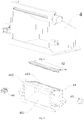
Fig. 1 is a schematic diagram showing a structure of an air duct switching component according to embodiments of the present invention; -
Fig. 2 is an explosive view of the air duct switching component according to embodiments of the present invention; -
Fig. 3 is a schematic diagram showing structures of an air duct assembly, a water container and an air duct switching component according to embodiments of the present invention, where the water container is pulled out from the air duct assembly; -
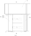
Fig. 4 is a front view of the air duct assembly, water container and the air duct switching component according to embodiments of the present invention; -
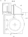
Fig. 5 is a schematic diagram showing a cross section along with line A-A ofFig. 4 ; -
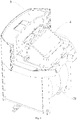
Fig. 6 is a perspective view of the air duct assembly, water container and the air duct switching component according to embodiments of the present invention; -
Fig. 7 is a schematic diagram showing structures of the air duct assembly, water container and the air duct switching component from another angle of view according to embodiments of the present invention; -
Fig. 8 is a sectional view of the air duct assembly, water container and the air duct switching component according to embodiments of the present invention; -
Fig. 9 is a schematic diagram showing structures of the air duct assembly, water container and the air duct switching component according to embodiments of the present invention, where the water container separates from the air duct assembly and air duct switching component; -
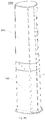
Fig. 10 is a schematic diagram showing a structure of a floor-standing air conditioner according to embodiments of the present invention; -
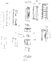
Fig. 11 is an explosive view of the floor-standing air conditioner according to embodiments of the present invention. - Reference numerals: floor-standing
air conditioner 1000,air handling device 100,body 1,body air inlet 11,body air outlet 12,air duct assembly 2,fan 21,fan air inlet 211,fan air outlet 212,water container 3,water tank 31,humidification component 32, airduct switching component 4,air outlet cover 41,air inlet 411,first air outlet 412,second air outlet 413,air switching plate 42,motor 43, waterlevel detection unit 44, purifyingdevice 200, indoorheat exchange device 300,heat exchanger 320, indoorheat exchange fan 310. - The embodiments of the present invention are described in detail below, examples of the embodiments are shown in the drawings, same or similar numerals throughout denote same or similar elements or the elements having same or similar functions. The following embodiments described with reference to the drawings are illustrative and only used to explain the present invention, but may not be interpreted as the restrictions of the present invention.
- In the description of the present invention, it will be appreciated that terms "center", "longitudinal", "lateral", "length", "width", "thickness", "upper", "lower", "front", "back", "left", "right", vertical", "horizontal", "top", "bottom", "inside", "outside", "clockwise", "anticlockwise", "axial", "radial", "circumferential" and other indicative directional or positional relation are the directional or positional relation based on the drawings, which is only intended to describe the present invention and simplify the description for convenience, but not to denote or hint that the indicated device or element must possess a specific direction, be constructed and operated in a specific direction, therefore, it should not be construed to limit the present invention. In addition, the features defining "first" and "second" may explicitly denote or impliedly include one or more of these features. In the description of the present invention, unless otherwise specified, "a plurality of" means two or more.
- In the description of the present invention, it should be noted that unless otherwise stipulated and defined explicitly, terms "mount", "link", "connect" should be regarded as general understanding, e.g., permanent connection, detachable connection, or integrated connection are available; both mechanical connection and electric connection are also available; direct link, indirect link by media, or inner communication between two element are available. Those ordinary skilled in the art may understand the specific meanings of the above terms in the present invention according to particular situations.
- A floor-standing
air conditioner 100 according to embodiments of the present invention will be described with reference toFig. 1-Fig. 11 . The floor-standingair conditioner 100 may be an air conditioner with cooling function only. The floor-standingair conditioner 100 may be also an air conditioner with cooling and heating functions certainly, namely, a cooling and heating machine. In the description of the application below, the floor-standingair conditioner 200, a cooling and heating machine, is set as an example for description. - As shown in
Fig. 1-Fig. 11 , the floor-standingair conditioner 100 according to embodiments of the present invention, e.g., a cooling and heating machine includes abody 1, anair duct assembly 2, awater container 3 and an airduct switching component 4. - As shown in
Fig. 4 andFig. 11 , abody air inlet 11 and abody air outlet 12 are formed on thebody 1, anair duct assembly 2 is disposed on thebody 1 and comprises afan 21, thefan 21 has afan air inlet 211 and afan air outlet 212, and thefan air inlet 211 communicates with thebody air inlet 11, so that thefan air inlet 211 may intake air from thebody air inlet 11. - As shown in
Fig. 1-Fig. 8 , awater container 3 is disposed on theair duct assembly 2, and awater tank 31 and ahumidification component 32 are disposed inside thewater container 3. An airduct switching component 4 includes anair outlet cover 41 and anair switching plate 42, and anair inlet 411, afirst air outlet 412 and asecond air outlet 413 spaced apart from each other are formed on theair outlet cover 41; theair inlet 411 communicates with thefan air outlet 212, and theair switching plate 42 is disposed on theair outlet cover 41; theair switching plate 42 may move between a first position where thefirst air outlet 412 is closed and thesecond air outlet 413 is opened and a second position where thefirst air outlet 412 is opened and thesecond air outlet 413 is closed. When theair switching plate 42 closes one of thefirst air outlet 412 and thesecond air outlet 413, theair inlet 411 communicates with thebody air outlet 12 via another one of thefirst air outlet 412 and thesecond air outlet 413, where thehumidification component 32 is disposed on thefirst air outlet 412. - It should be noted that the first position is a position status (not as shown in the figure) where the
first air outlet 412 is closed by theair switching plate 42 and airflow is suitable for flowing to thebody air outlet 12 via thesecond air outlet 413, and the second position is a position status (as shown inFig. 1 andFig. 5 ) where thesecond air outlet 413 is closed by theair switching plate 42 and airflow is suitable for flowing to thebody air outlet 12 by thefirst air outlet 412. Theair switching plate 42 may move back and forth between the first position and the second position, moreover, may keep still at anywhere between the first position and the second position according to requirements. At this time, airflow may discharge from both sides of theair switching plate 42, namely, partial airflow flows out of thefirst air outlet 412, and another airflow flows out of thesecond air outlet 413. - The
water tank 31 may store a certain amount of liquid, e.g., water, etc., so that airflow may be humidified while flowing through thehumidification component 32. Theair inlet 411 communicates with thebody air outlet 12 via thesecond air outlet 413, and airflow flows out of thesecond air outlet 413 when thefirst air outlet 412 is completely closed by the air switching plate 42 (namely, theair switching plate 42 is located in the first position), at this time, the airflow is not humidified by thehumidification component 32 as not flow therethrough; when thesecond air outlet 413 is completely closed by the air switching plate 42 (namely, theair switching plate 42 is located in the second position), theair inlet 411 communicates with thebody air outlet 12 by thefirst air outlet 412, and airflow flows out of thefirst air outlet 412, furthermore, the airflow is humidified by thehumidification component 32 when flow therethrough; when theair switching plate 42 is located between the first position and the second position (exclusive of the above first position and the second position), airflow may flow out of thefirst air outlet 412 and thesecond air outlet 413, and at this time, partial airflow from thefirst air outlet 412 is only humidified, which achieves the purpose of airflow humidification similarly as well. - Therefore, airflow flows out of the
second air outlet 413 and is not humidified when theair switching plate 42 is located in the first position, the floor-standingair conditioner 100 may achieve non-humidified air discharge; when theair switching plate 42 is located in the second position, airflow may only flow out of thefirst air outlet 412 and is humidified by thehumidification component 32 at this time and the floor-standingair conditioner 100 may achieve humidified air discharge with the maximum humidifying capacity; when theswitching plate 42 is located between the first position and the second position, the floor-standingair conditioner 100 may also achieve humidified air discharge, and at this time, the specific humidity of the discharged air may be adjusted according to actual demands accordingly. Here it should be noted that thehumidification component 32 may be not only used to humidify the airflow flowing therethrough (e.g., air, etc.), but also have a cleaning function, specifically, thehumidification component 32 may precipitate particulate matters in the air, thus refreshing the air. - It is appreciated that when the
switching plate 42 is located between the first position and the second position, the smaller the included angle between theair switching plate 42 and the plane of thefirst position 412 is, the lower the humidity of the discharged air in the floor-standingair conditioner 100 is; the larger the included angle between theair switching plate 42 and the plane of thefirst position 412 is, the higher the humidity of the discharged air from the floor-standingair conditioner 100 is. - According to the floor-standing
air conditioner 100 of embodiments of the present invention, the airduct switching component 4 is arranged in thefan air outlet 212 of theair duct assembly 2 and thehumidification component 32 is arranged in thefirst air outlet 412 of the airduct switching component 4, such that a position of theair switching plate 42 is adjusted to adjust an airflow path and humidified or non-humidified air is discharged from the floor-standingair conditioner 100, moreover, the humidity of the discharged air from the floor-standingair conditioner 100 may be adjusted according to users' demands, thus improving users' experience. - As shown in
Fig. 3 , in some embodiments of the present invention, thewater container 3 may be disposed on theair duct assembly 2 in a push-pull way, where thewater tank 31 and thehumidification component 32 may be detachably disposed inside thewater container 3. Specifically, for example, thewater container 3 may be pulled forward from the air duct assembly 2 (as shown inFig. 3 ). At this time, thewater tank 31 may be taken out of thewater container 3, so that liquid, e.g., water, etc. is added to thewater tank 31, and moreover, in case that thehumidification component 32 is aging or fails, thehumidification component 32 may be disassembled for replacement. Thewater container 3 may be pushed back to the right above of theair duct assembly 2 when there is enough water in thewater tank 31, namely, the status of not pulling the water container 3 (refer toFig. 5 ), therefore, it is easy and simple to handle, and it has reasonable layout. - As shown in
Fig. 9 , in some embodiments of the present invention, thewater container 3 is detachably disposed on theair duct assembly 2,Fig. 9 shows a status of taking thewater container 3 out of theair duct assembly 2, so as to be convenient for the supplementation of the water in thewater tank 31, and for the cleaning of thewater container 3, meanwhile, it is easy to handle. - As shown in
Fig. 3-Fig. 9 , in the floor-standingair conditioner 100 of some embodiments of the present invention, thewater container 3 and theair duct assembly 4 are disposed on the top of theair duct assembly 2, thefan air outlet 212 is formed on the top of thefan 21, theair inlet 411 is formed at the bottom of theair outlet cover 41 to be connected with thefan air outlet 212, thefirst air outlet 412 is formed on a side wall of theair outlet cover 41 and arranged vertically, and thesecond air outlet 413 is formed on the top of theair outlet cover 41 and arranged slantwise relative to thefirst air outlet 412. Thus, the layout among thewater container 3, airduct switching component 4 and thefan 21 is more reasonable, moreover, the airflow has a shorter path, small flow loss and low noise in the process of flowing through the airduct switching component 4 from thefan 21. - It is appreciated that as shown in
Fig. 3 andFig. 9 , when thewater container 3 is taken out, thefirst air outlet 412 is open and thefan 21 communicates with the outside at this time, dust and other pollutants easily invade into thefan 21, the position of theair switching plate 42 is adjusted, e.g., theair switching plate 42 is switched to the first position to shield thefirst air outlet 412, so that thefan 21 may be protected by the airduct switching component 4, which effectively prevents dust, etc. from entering into thefan 21 via the airduct switching component 4, thus ensuring a clean airflow path, guaranteeing normal operation of thefan 21 and extending the service life of thefan 21. - As shown in
Fig. 5- Fig. 8 , further, thewater tank 31 is located at one side of thehumidification component 32 away from thefirst air outlet 412 and is spaced apart from thehumidification component 32, thus guaranteeing the volume of the airflow while flowing through thehumidification component 32, achieving a more compact structure between thewater container 3 and the airduct switching component 4 as well as achieving a more reasonable layout among components. - As shown in
Fig. 5 , one end (e.g., a left end inFig. 5 ) of thesecond air outlet 413 is adjacent to an upper end of thefirst air outlet 412, another end (e.g., a right end inFig. 5 ) of thesecond air outlet 413 slantwise extends downwards away from thefirst air outlet 412. The configuration of the structure may effectively save the space occupied by the airduct switching component 4, and decrease the included angle between the plane of thefirst air outlet 412 and the plane of thesecond air outlet 413, which facilitates the outflow of the airflow from the airduct switching component 4, thus achieving the switch of airflow humidification status better, namely, the switch of the air discharge modes (humidified or non-humidified) can be achieved via rotating a smaller angle of theair switching plate 42 only; meanwhile, the structure is simple and has more reasonable layout. - As shown in
Fig. 3 andFig. 5 , in some embodiments of the present invention, one end of theair switching plate 42 is located between the one end of thesecond air outlet 413 and the upper end of thefirst air outlet 412, moreover, the above one end of theair switching plate 42 is pivotally connected with theair outlet cover 41. The connection mode is simple, and theair switching plate 42 may be rotated to different angles conveniently, thus adjusting the mode of air discharge from the floor-standingair conditioner 100. - Referring to
Fig. 1 and Fig. 2 , further, theair outlet cover 41 is provided with amotor 43, and themotor 43 is connected with the one end of theair switching plate 42, so as to drive theair switching plate 42 to rotate between the first position and the second position, which is easy to drive theair switching plate 42 for rotation accordingly. Moreover, the mode is simple and reliable. - Optionally, the
humidification component 32 is a wet film, the wet film may absorb water from the water container, thus ensuring that thehumidification component 32 is in a humidification status, and when air flows through the wet film, the wet film may precipitate particles in the air, thus keeping good humidification effect and refreshing air. The wet film may be prepared by adding special chemical raw materials to plant fiber or glass fiber, and it has good water absorption and evaporability. - It is appreciated that the
humidification component 32 may be periodically taken out for cleaning and replacement, thus guaranteeing good humidification effect and air refreshing effect. - Optionally, referring to
Fig. 10 andFig. 11 , thefan air inlet 211 may be further provided with apurification device 200, and at this time, thepurification device 200 may be disposed at the upstream of thefan 21; thepurification device 200 may purify and filter the air flowing into thefan 21 well, thus purifying the air and improving users' experience. Here it should be noted that the "upstream" may be construed as the upstream of the flow direction of airflow respectively. - As shown in
Fig. 10 andFig. 11 , the floor-standingair conditioner 100 includes an indoorheat exchange device 300 and anair handling device 100, and theair handling device 100 may be disposed below the indoorheat exchange device 300. Theair handling device 100 may be further disposed above the indoor heat exchange device 300 (not as shown in the figure) certainly. Theair handling device 100 includes the above air duct assembly, water container, air duct switching component, etc., thus humidifying the airflow flowing therethrough (e.g., air, etc.). Further, thepurification device 200 may be arranged in the upstream of the fan air inlet of the fan, thus humidifying the airflow flowing therethrough (e.g., air, etc.). - The indoor
heat exchange device 300 is used to cool or warm the airflow (e.g., air, etc.) flowing through the indoorheat exchange device 300, thus achieving the purpose of refrigerating or heating. The indoorheat exchange device 300 may have cooling function only, of course have refrigerating or heating functions at the same time. The indoorheat exchange device 300 may include aheat exchanger 320, an indoorheat exchange fan 310, etc. It is appreciated that the concrete structure and working principle of the indoorheat exchange device 300 have been well known to those skilled in the art, and thus will not be described in detail here. - The working process of a floor-standing
air conditioner 100 in one embodiment of the present invention is described in detail with reference toFig. 1-Fig. 11 : - Air flows into a
body 1 via abody air inlet 11 and thebody air inlet 11 communicates with afan air inlet 211 when the floor-standingair conditioner 100 works. Air enters into afan 21 via thefan air inlet 211 and is purified by apurification device 200 at thefan air inlet 211, thus improving the air quality of thefan 21, protecting thefan 21 and extending the service life of thefan 21. - Under the action of the
fan 21, air flows out of afan air outlet 212, and thefan air outlet 212 communicates with anair inlet 411 of an airduct switching component 4. At this time, a position of anair switching plate 42 in the airduct switching component 4 may be adjusted according to user's actual demands, e.g., theair switching plate 42 may be adjusted between the first position and the second position, or in the second position when the floor-standingair conditioner 100 is required to discharge humidified air, and when theair switching plate 42 is located in the second position, the humidifying effect is up to the maximum. When theair switching plate 42 is adjusted between the first position and the second position, the air gathers after flowing out of thefirst air outlet 412 and thesecond air outlet 413, and flows to thebody air outlet 12 through an airflow path, thus flowing out of thebody air outlet 12. The rotating angle of theair switching plate 42 may be adjusted according to the user's demand for the humidity of the discharged air from the floor-standingair conditioner 100. - The
air switching plate 42 may be adjusted to the first position, namely, thefirst air outlet 412 is closed when the floor-standingair conditioner 100 is not requested to discharge humidified air. Thus, different humidity of air may be discharged and the air is purified, thus improving users' experience. - In the description of the specification, terms "one embodiment", "some embodiments", "schematic embodiment", "example", or "some examples" and other description denote a specific feature, structure, material or characteristic described with reference to the embodiment or example, which are included in at least one embodiment or example of the present invention. In the specification, schematic expression of the above terms does not always refer to a same embodiment or example. Moreover, the specific feature, structure, material or characteristic described may be appropriately combined in any one or more embodiments or examples.
- Although embodiments of the present invention have been indicated and described, it can be understood for those ordinary skill in the art that: various changes, modifications, substitutions and variations of these embodiments may be made within the principle and spirit of the present invention, and the scope of the present invention is limited by claims and equivalents thereof.
Claims (9)
- A floor-standing air conditioner, comprising:a body, wherein a body air inlet and a body air outlet are formed on the body;an air duct assembly, wherein the air duct assembly is disposed on the body and comprises a fan, the fan has a fan air inlet and a fan air outlet, and the fan air inlet communicates with the body air inlet;a water container, wherein the water container is disposed on the air duct assembly, and a water tank and a humidification component are disposed inside the water container;an air duct switching component, wherein the air duct switching component comprises an air outlet cover and an air switching plate, and an air inlet, a first air outlet and a second air outlet spaced apart from each other are formed on the air outlet cover, the air inlet communicates with the fan air outlet, and the air switching plate is disposed on the air outlet cover, the air switching plate may move between a first position where the first air outlet is closed and the second air outlet is opened and a second position where the first air outlet is opened and the second air outlet is closed, when the air switching plate closes one of the first air outlet and the second air outlet, the air inlet communicates with the body air outlet via another one of the first air outlet and the second air outlet, where the humidification component is disposed on the first air outlet.
- The floor-standing air conditioner according to claim 1, wherein the water container may be disposed on the air duct assembly in a push-pull way, and the water tank and the humidification component may be detachably disposed inside the water container.
- The floor-standing air conditioner according to claim 1, wherein the water container may be detachably disposed on the air duct assembly.
- The floor-standing air conditioner according to any one of claims 1-3, wherein the water container and the air duct switching component are disposed on a top of the air duct assembly, the fan air outlet is formed on a top of the fan, the air inlet is formed at the bottom of the air outlet cover to be connected with the fan air outlet, the first air outlet is formed on a side wall of the air outlet cover and arranged vertically, and the second air outlet is formed on a top of the air outlet cover and arranged slantwise relative to the first air outlet.
- The floor-standing air conditioner according to claim 4, wherein the water tank is located at one side of the humidification component away from the first air outlet and is spaced apart from the humidification component.
- The floor-standing air conditioner according to claim 4, wherein one end of the second air outlet is adjacent to an upper end of the first air outlet, another end of the second air outlet slantwise extends downwards away from the first air outlet.
- The floor-standing air conditioner according to claim 6, wherein one end of the air switching plate is located between the one end of the second air outlet and the upper end of the first air outlet as well as is pivotally connected with the air outlet cover.
- The floor-standing air conditioner according to claim 7, wherein the air outlet cover is provided with a motor, and the motor is connected with the one end of the air switching plate, so as to drive the air switching plate to rotate between the first position and the second position.
- The floor-standing air conditioner according to claim 1, wherein the humidification component is a wet film.
Applications Claiming Priority (3)
| Application Number | Priority Date | Filing Date | Title |
|---|---|---|---|
| CN201820174493.4U CN207962892U (en) | 2018-01-30 | 2018-01-30 | Cabinet-type air conditioner |
| CN201810091057.5A CN108105881B (en) | 2018-01-30 | 2018-01-30 | Cabinet-type air conditioner |
| PCT/CN2018/092681 WO2019148750A1 (en) | 2018-01-30 | 2018-06-25 | Floor-standing air conditioner |
Publications (3)
| Publication Number | Publication Date |
|---|---|
| EP3587936A1 true EP3587936A1 (en) | 2020-01-01 |
| EP3587936A4 EP3587936A4 (en) | 2021-02-17 |
| EP3587936B1 EP3587936B1 (en) | 2023-05-03 |
Family
ID=67477956
Family Applications (1)
| Application Number | Title | Priority Date | Filing Date |
|---|---|---|---|
| EP18904311.0A Active EP3587936B1 (en) | 2018-01-30 | 2018-06-25 | Floor-standing air conditioner |
Country Status (5)
| Country | Link |
|---|---|
| US (1) | US11333368B2 (en) |
| EP (1) | EP3587936B1 (en) |
| JP (1) | JP7015844B2 (en) |
| KR (1) | KR102309242B1 (en) |
| WO (1) | WO2019148750A1 (en) |
Families Citing this family (3)
| Publication number | Priority date | Publication date | Assignee | Title |
|---|---|---|---|---|
| US9861778B2 (en) * | 2013-03-15 | 2018-01-09 | Resmed Limited | Humidifier reservoir |
| CN113446723B (en) * | 2021-07-19 | 2024-12-13 | 珠海格力电器股份有限公司 | Panel components and air conditioners |
| EP4296584A1 (en) * | 2022-06-23 | 2023-12-27 | AERMEC S.p.A. | Fan coil unit |
Family Cites Families (26)
| Publication number | Priority date | Publication date | Assignee | Title |
|---|---|---|---|---|
| JPS5112302Y2 (en) | 1973-06-20 | 1976-04-02 | ||
| JPS531955U (en) | 1976-06-24 | 1978-01-10 | ||
| JPH0735371A (en) | 1993-07-22 | 1995-02-07 | Fujita Corp | Floor cooling method |
| JPH07269937A (en) * | 1994-03-30 | 1995-10-20 | Shinko Kogyo Co Ltd | Floor-standing air conditioner |
| US6427454B1 (en) * | 2000-02-05 | 2002-08-06 | Michael K. West | Air conditioner and controller for active dehumidification while using ambient air to prevent overcooling |
| JP2002066251A (en) * | 2000-08-28 | 2002-03-05 | Tokyo Gas Co Ltd | Dehumidifying and humidifying equipment |
| JP2002106969A (en) * | 2000-09-29 | 2002-04-10 | Matsushita Seiko Co Ltd | Hot air heater with humidification function |
| JP2008200615A (en) | 2007-02-21 | 2008-09-04 | Matsushita Electric Ind Co Ltd | Dehumidifier |
| JP2009257632A (en) | 2008-04-14 | 2009-11-05 | Daikin Ind Ltd | Air conditioner |
| JP5465477B2 (en) | 2009-06-30 | 2014-04-09 | 三洋電機株式会社 | Filter device |
| JP2011033218A (en) * | 2009-07-30 | 2011-02-17 | Daikin Industries Ltd | Floor type indoor unit and air conditioner having the same |
| JP2012068005A (en) | 2010-08-27 | 2012-04-05 | Panasonic Corp | Humidification air cleaner |
| JP2013068352A (en) | 2011-09-22 | 2013-04-18 | Panasonic Corp | Humidifier, and hot-air humidifier including the same |
| CN203132000U (en) | 2013-03-22 | 2013-08-14 | 广州宏晓电子科技有限公司 | Air purification device |
| CN203323264U (en) | 2013-07-05 | 2013-12-04 | 台州创兴环保科技有限公司 | Air purification and humidification system |
| JP6164264B2 (en) | 2013-09-30 | 2017-07-19 | ダイキン工業株式会社 | Air cleaner |
| JP2015145737A (en) | 2014-01-31 | 2015-08-13 | ダイキン工業株式会社 | Air purifier with humidification function |
| CN111365775A (en) * | 2014-12-10 | 2020-07-03 | 豪威株式会社 | Dehumidifying and humidifying device, dehumidifying air cleaner, humidifying air cleaner, and method of operating the same |
| JP6495081B2 (en) | 2015-04-17 | 2019-04-03 | 株式会社コロナ | Mist generator |
| JP2017020710A (en) | 2015-07-10 | 2017-01-26 | パナソニックIpマネジメント株式会社 | Air purifier and air purifier with humidification function |
| JP6529869B2 (en) | 2015-09-11 | 2019-06-12 | ダイニチ工業株式会社 | Warm air heater with humidification function |
| CN107218663A (en) | 2017-07-11 | 2017-09-29 | 海信(山东)空调有限公司 | A kind of indoor air conditioner cabinet |
| CN107327937B (en) | 2017-08-18 | 2020-03-06 | 广东美的制冷设备有限公司 | Air treatment module and air conditioner |
| CN107327944A (en) | 2017-08-18 | 2017-11-07 | 广东美的制冷设备有限公司 | Vertical air-conditioner indoor unit and air conditioner |
| CN108105881B (en) | 2018-01-30 | 2020-08-25 | 广东美的制冷设备有限公司 | Cabinet-type air conditioner |
| CN207962892U (en) | 2018-01-30 | 2018-10-12 | 广东美的制冷设备有限公司 | Cabinet-type air conditioner |
-
2018
- 2018-06-25 JP JP2019552123A patent/JP7015844B2/en active Active
- 2018-06-25 KR KR1020197029797A patent/KR102309242B1/en active Active
- 2018-06-25 WO PCT/CN2018/092681 patent/WO2019148750A1/en not_active Ceased
- 2018-06-25 EP EP18904311.0A patent/EP3587936B1/en active Active
- 2018-06-25 US US16/497,499 patent/US11333368B2/en active Active
Also Published As
| Publication number | Publication date |
|---|---|
| US20200063985A1 (en) | 2020-02-27 |
| EP3587936B1 (en) | 2023-05-03 |
| KR20190124298A (en) | 2019-11-04 |
| WO2019148750A1 (en) | 2019-08-08 |
| EP3587936A4 (en) | 2021-02-17 |
| JP2020516839A (en) | 2020-06-11 |
| KR102309242B1 (en) | 2021-10-06 |
| US11333368B2 (en) | 2022-05-17 |
| JP7015844B2 (en) | 2022-02-03 |
Similar Documents
| Publication | Publication Date | Title |
|---|---|---|
| CN108105881B (en) | Cabinet-type air conditioner | |
| CN107504605B (en) | Air treatment device and vertical air conditioner with same | |
| CN107477675B (en) | Indoor unit of vertical air conditioner and air conditioner with indoor unit | |
| CN212618769U (en) | Heat exchanger assembly and air conditioner indoor unit with same | |
| CN108266800B (en) | Cabinet air conditioner and air conditioner with same | |
| US11333368B2 (en) | Floor-standing air conditioner | |
| CN207962892U (en) | Cabinet-type air conditioner | |
| CN108087985B (en) | Cabinet air conditioner and air conditioner with same | |
| CN108006834B (en) | Cabinet air conditioner and air conditioner with same | |
| CN108006837B (en) | Cabinet air conditioner and air conditioner with same | |
| CN104422050B (en) | cooling fan | |
| CN108644896B (en) | Fresh air conditioner all-in-one machine | |
| EP2436996B1 (en) | Ventilating apparatus | |
| WO2019024462A1 (en) | Air treatment apparatus, and air-conditioner indoor unit and air-conditioner outdoor unit having same | |
| KR101170599B1 (en) | Apparatus for air purifying and humidifying | |
| CN110701717B (en) | A fresh air device and its indoor unit for changing fresh air | |
| CN216522029U (en) | Air treatment device and air conditioner | |
| CN108105877B (en) | Air conditioner | |
| CN219243765U (en) | dehumidifier | |
| TWI292810B (en) | Air conditioner | |
| CN216868674U (en) | Air conditioning equipment | |
| CN216769595U (en) | Anhydrous humidification device and air conditioner | |
| CN106949586B (en) | Anhydrous humidification device and air conditioner | |
| CN214406255U (en) | Air conditioner indoor unit and air conditioner | |
| CN115978663A (en) | dehumidifier |
Legal Events
| Date | Code | Title | Description |
|---|---|---|---|
| STAA | Information on the status of an ep patent application or granted ep patent |
Free format text: STATUS: THE INTERNATIONAL PUBLICATION HAS BEEN MADE |
|
| PUAI | Public reference made under article 153(3) epc to a published international application that has entered the european phase |
Free format text: ORIGINAL CODE: 0009012 |
|
| STAA | Information on the status of an ep patent application or granted ep patent |
Free format text: STATUS: REQUEST FOR EXAMINATION WAS MADE |
|
| 17P | Request for examination filed |
Effective date: 20190923 |
|
| AK | Designated contracting states |
Kind code of ref document: A1 Designated state(s): AL AT BE BG CH CY CZ DE DK EE ES FI FR GB GR HR HU IE IS IT LI LT LU LV MC MK MT NL NO PL PT RO RS SE SI SK SM TR |
|
| AX | Request for extension of the european patent |
Extension state: BA ME |
|
| A4 | Supplementary search report drawn up and despatched |
Effective date: 20210119 |
|
| RIC1 | Information provided on ipc code assigned before grant |
Ipc: F24F 11/89 20180101ALI20210113BHEP Ipc: F24F 6/00 20060101ALI20210113BHEP Ipc: F24F 3/14 20060101ALI20210113BHEP Ipc: F24F 11/81 20180101ALI20210113BHEP Ipc: F24F 1/037 20190101ALI20210113BHEP Ipc: F24F 1/0022 20190101ALI20210113BHEP Ipc: F24F 1/00 20190101AFI20210113BHEP Ipc: F24F 6/04 20060101ALI20210113BHEP Ipc: F24F 1/005 20190101ALI20210113BHEP Ipc: F24F 11/72 20180101ALI20210113BHEP Ipc: F24F 12/00 20060101ALI20210113BHEP Ipc: F24F 11/84 20180101ALI20210113BHEP Ipc: F24F 1/0014 20190101ALI20210113BHEP Ipc: F24F 1/029 20190101ALI20210113BHEP Ipc: F24F 1/0087 20190101ALI20210113BHEP Ipc: F24F 13/14 20060101ALI20210113BHEP |
|
| DAV | Request for validation of the european patent (deleted) | ||
| DAX | Request for extension of the european patent (deleted) | ||
| GRAP | Despatch of communication of intention to grant a patent |
Free format text: ORIGINAL CODE: EPIDOSNIGR1 |
|
| STAA | Information on the status of an ep patent application or granted ep patent |
Free format text: STATUS: GRANT OF PATENT IS INTENDED |
|
| GRAS | Grant fee paid |
Free format text: ORIGINAL CODE: EPIDOSNIGR3 |
|
| INTG | Intention to grant announced |
Effective date: 20230228 |
|
| GRAA | (expected) grant |
Free format text: ORIGINAL CODE: 0009210 |
|
| STAA | Information on the status of an ep patent application or granted ep patent |
Free format text: STATUS: THE PATENT HAS BEEN GRANTED |
|
| AK | Designated contracting states |
Kind code of ref document: B1 Designated state(s): AL AT BE BG CH CY CZ DE DK EE ES FI FR GB GR HR HU IE IS IT LI LT LU LV MC MK MT NL NO PL PT RO RS SE SI SK SM TR |
|
| REG | Reference to a national code |
Ref country code: GB Ref legal event code: FG4D |
|
| REG | Reference to a national code |
Ref country code: AT Ref legal event code: REF Ref document number: 1564892 Country of ref document: AT Kind code of ref document: T Effective date: 20230515 Ref country code: CH Ref legal event code: EP |
|
| REG | Reference to a national code |
Ref country code: DE Ref legal event code: R096 Ref document number: 602018049424 Country of ref document: DE |
|
| REG | Reference to a national code |
Ref country code: IE Ref legal event code: FG4D |
|
| REG | Reference to a national code |
Ref country code: LT Ref legal event code: MG9D |
|
| REG | Reference to a national code |
Ref country code: NL Ref legal event code: MP Effective date: 20230503 |
|
| REG | Reference to a national code |
Ref country code: AT Ref legal event code: MK05 Ref document number: 1564892 Country of ref document: AT Kind code of ref document: T Effective date: 20230503 |
|
| PG25 | Lapsed in a contracting state [announced via postgrant information from national office to epo] |
Ref country code: SE Free format text: LAPSE BECAUSE OF FAILURE TO SUBMIT A TRANSLATION OF THE DESCRIPTION OR TO PAY THE FEE WITHIN THE PRESCRIBED TIME-LIMIT Effective date: 20230503 Ref country code: PT Free format text: LAPSE BECAUSE OF FAILURE TO SUBMIT A TRANSLATION OF THE DESCRIPTION OR TO PAY THE FEE WITHIN THE PRESCRIBED TIME-LIMIT Effective date: 20230904 Ref country code: NO Free format text: LAPSE BECAUSE OF FAILURE TO SUBMIT A TRANSLATION OF THE DESCRIPTION OR TO PAY THE FEE WITHIN THE PRESCRIBED TIME-LIMIT Effective date: 20230803 Ref country code: NL Free format text: LAPSE BECAUSE OF FAILURE TO SUBMIT A TRANSLATION OF THE DESCRIPTION OR TO PAY THE FEE WITHIN THE PRESCRIBED TIME-LIMIT Effective date: 20230503 Ref country code: ES Free format text: LAPSE BECAUSE OF FAILURE TO SUBMIT A TRANSLATION OF THE DESCRIPTION OR TO PAY THE FEE WITHIN THE PRESCRIBED TIME-LIMIT Effective date: 20230503 Ref country code: AT Free format text: LAPSE BECAUSE OF FAILURE TO SUBMIT A TRANSLATION OF THE DESCRIPTION OR TO PAY THE FEE WITHIN THE PRESCRIBED TIME-LIMIT Effective date: 20230503 |
|
| PG25 | Lapsed in a contracting state [announced via postgrant information from national office to epo] |
Ref country code: RS Free format text: LAPSE BECAUSE OF FAILURE TO SUBMIT A TRANSLATION OF THE DESCRIPTION OR TO PAY THE FEE WITHIN THE PRESCRIBED TIME-LIMIT Effective date: 20230503 Ref country code: PL Free format text: LAPSE BECAUSE OF FAILURE TO SUBMIT A TRANSLATION OF THE DESCRIPTION OR TO PAY THE FEE WITHIN THE PRESCRIBED TIME-LIMIT Effective date: 20230503 Ref country code: LV Free format text: LAPSE BECAUSE OF FAILURE TO SUBMIT A TRANSLATION OF THE DESCRIPTION OR TO PAY THE FEE WITHIN THE PRESCRIBED TIME-LIMIT Effective date: 20230503 Ref country code: LT Free format text: LAPSE BECAUSE OF FAILURE TO SUBMIT A TRANSLATION OF THE DESCRIPTION OR TO PAY THE FEE WITHIN THE PRESCRIBED TIME-LIMIT Effective date: 20230503 Ref country code: IS Free format text: LAPSE BECAUSE OF FAILURE TO SUBMIT A TRANSLATION OF THE DESCRIPTION OR TO PAY THE FEE WITHIN THE PRESCRIBED TIME-LIMIT Effective date: 20230903 Ref country code: HR Free format text: LAPSE BECAUSE OF FAILURE TO SUBMIT A TRANSLATION OF THE DESCRIPTION OR TO PAY THE FEE WITHIN THE PRESCRIBED TIME-LIMIT Effective date: 20230503 Ref country code: GR Free format text: LAPSE BECAUSE OF FAILURE TO SUBMIT A TRANSLATION OF THE DESCRIPTION OR TO PAY THE FEE WITHIN THE PRESCRIBED TIME-LIMIT Effective date: 20230804 |
|
| PG25 | Lapsed in a contracting state [announced via postgrant information from national office to epo] |
Ref country code: FI Free format text: LAPSE BECAUSE OF FAILURE TO SUBMIT A TRANSLATION OF THE DESCRIPTION OR TO PAY THE FEE WITHIN THE PRESCRIBED TIME-LIMIT Effective date: 20230503 |
|
| PG25 | Lapsed in a contracting state [announced via postgrant information from national office to epo] |
Ref country code: SK Free format text: LAPSE BECAUSE OF FAILURE TO SUBMIT A TRANSLATION OF THE DESCRIPTION OR TO PAY THE FEE WITHIN THE PRESCRIBED TIME-LIMIT Effective date: 20230503 |
|
| PG25 | Lapsed in a contracting state [announced via postgrant information from national office to epo] |
Ref country code: SM Free format text: LAPSE BECAUSE OF FAILURE TO SUBMIT A TRANSLATION OF THE DESCRIPTION OR TO PAY THE FEE WITHIN THE PRESCRIBED TIME-LIMIT Effective date: 20230503 Ref country code: SK Free format text: LAPSE BECAUSE OF FAILURE TO SUBMIT A TRANSLATION OF THE DESCRIPTION OR TO PAY THE FEE WITHIN THE PRESCRIBED TIME-LIMIT Effective date: 20230503 Ref country code: RO Free format text: LAPSE BECAUSE OF FAILURE TO SUBMIT A TRANSLATION OF THE DESCRIPTION OR TO PAY THE FEE WITHIN THE PRESCRIBED TIME-LIMIT Effective date: 20230503 Ref country code: EE Free format text: LAPSE BECAUSE OF FAILURE TO SUBMIT A TRANSLATION OF THE DESCRIPTION OR TO PAY THE FEE WITHIN THE PRESCRIBED TIME-LIMIT Effective date: 20230503 Ref country code: DK Free format text: LAPSE BECAUSE OF FAILURE TO SUBMIT A TRANSLATION OF THE DESCRIPTION OR TO PAY THE FEE WITHIN THE PRESCRIBED TIME-LIMIT Effective date: 20230503 Ref country code: CZ Free format text: LAPSE BECAUSE OF FAILURE TO SUBMIT A TRANSLATION OF THE DESCRIPTION OR TO PAY THE FEE WITHIN THE PRESCRIBED TIME-LIMIT Effective date: 20230503 |
|
| REG | Reference to a national code |
Ref country code: CH Ref legal event code: PL |
|
| REG | Reference to a national code |
Ref country code: DE Ref legal event code: R097 Ref document number: 602018049424 Country of ref document: DE |
|
| REG | Reference to a national code |
Ref country code: BE Ref legal event code: MM Effective date: 20230630 |
|
| PG25 | Lapsed in a contracting state [announced via postgrant information from national office to epo] |
Ref country code: MC Free format text: LAPSE BECAUSE OF FAILURE TO SUBMIT A TRANSLATION OF THE DESCRIPTION OR TO PAY THE FEE WITHIN THE PRESCRIBED TIME-LIMIT Effective date: 20230503 |
|
| PG25 | Lapsed in a contracting state [announced via postgrant information from national office to epo] |
Ref country code: MC Free format text: LAPSE BECAUSE OF FAILURE TO SUBMIT A TRANSLATION OF THE DESCRIPTION OR TO PAY THE FEE WITHIN THE PRESCRIBED TIME-LIMIT Effective date: 20230503 |
|
| PG25 | Lapsed in a contracting state [announced via postgrant information from national office to epo] |
Ref country code: LU Free format text: LAPSE BECAUSE OF NON-PAYMENT OF DUE FEES Effective date: 20230625 |
|
| PLBE | No opposition filed within time limit |
Free format text: ORIGINAL CODE: 0009261 |
|
| STAA | Information on the status of an ep patent application or granted ep patent |
Free format text: STATUS: NO OPPOSITION FILED WITHIN TIME LIMIT |
|
| REG | Reference to a national code |
Ref country code: IE Ref legal event code: MM4A |
|
| PG25 | Lapsed in a contracting state [announced via postgrant information from national office to epo] |
Ref country code: LU Free format text: LAPSE BECAUSE OF NON-PAYMENT OF DUE FEES Effective date: 20230625 |
|
| 26N | No opposition filed |
Effective date: 20240206 |
|
| PG25 | Lapsed in a contracting state [announced via postgrant information from national office to epo] |
Ref country code: IE Free format text: LAPSE BECAUSE OF NON-PAYMENT OF DUE FEES Effective date: 20230625 |
|
| GBPC | Gb: european patent ceased through non-payment of renewal fee |
Effective date: 20230803 |
|
| PG25 | Lapsed in a contracting state [announced via postgrant information from national office to epo] |
Ref country code: IE Free format text: LAPSE BECAUSE OF NON-PAYMENT OF DUE FEES Effective date: 20230625 Ref country code: CH Free format text: LAPSE BECAUSE OF NON-PAYMENT OF DUE FEES Effective date: 20230630 |
|
| PG25 | Lapsed in a contracting state [announced via postgrant information from national office to epo] |
Ref country code: SI Free format text: LAPSE BECAUSE OF FAILURE TO SUBMIT A TRANSLATION OF THE DESCRIPTION OR TO PAY THE FEE WITHIN THE PRESCRIBED TIME-LIMIT Effective date: 20230503 |
|
| PG25 | Lapsed in a contracting state [announced via postgrant information from national office to epo] |
Ref country code: BE Free format text: LAPSE BECAUSE OF NON-PAYMENT OF DUE FEES Effective date: 20230630 Ref country code: SI Free format text: LAPSE BECAUSE OF FAILURE TO SUBMIT A TRANSLATION OF THE DESCRIPTION OR TO PAY THE FEE WITHIN THE PRESCRIBED TIME-LIMIT Effective date: 20230503 Ref country code: IT Free format text: LAPSE BECAUSE OF FAILURE TO SUBMIT A TRANSLATION OF THE DESCRIPTION OR TO PAY THE FEE WITHIN THE PRESCRIBED TIME-LIMIT Effective date: 20230503 |
|
| PG25 | Lapsed in a contracting state [announced via postgrant information from national office to epo] |
Ref country code: GB Free format text: LAPSE BECAUSE OF NON-PAYMENT OF DUE FEES Effective date: 20230803 |
|
| PG25 | Lapsed in a contracting state [announced via postgrant information from national office to epo] |
Ref country code: GB Free format text: LAPSE BECAUSE OF NON-PAYMENT OF DUE FEES Effective date: 20230803 |
|
| PG25 | Lapsed in a contracting state [announced via postgrant information from national office to epo] |
Ref country code: BG Free format text: LAPSE BECAUSE OF FAILURE TO SUBMIT A TRANSLATION OF THE DESCRIPTION OR TO PAY THE FEE WITHIN THE PRESCRIBED TIME-LIMIT Effective date: 20230503 |
|
| PG25 | Lapsed in a contracting state [announced via postgrant information from national office to epo] |
Ref country code: BG Free format text: LAPSE BECAUSE OF FAILURE TO SUBMIT A TRANSLATION OF THE DESCRIPTION OR TO PAY THE FEE WITHIN THE PRESCRIBED TIME-LIMIT Effective date: 20230503 |
|
| PGFP | Annual fee paid to national office [announced via postgrant information from national office to epo] |
Ref country code: DE Payment date: 20250625 Year of fee payment: 8 |
|
| PGFP | Annual fee paid to national office [announced via postgrant information from national office to epo] |
Ref country code: FR Payment date: 20250620 Year of fee payment: 8 |
|
| PG25 | Lapsed in a contracting state [announced via postgrant information from national office to epo] |
Ref country code: CY Free format text: LAPSE BECAUSE OF FAILURE TO SUBMIT A TRANSLATION OF THE DESCRIPTION OR TO PAY THE FEE WITHIN THE PRESCRIBED TIME-LIMIT; INVALID AB INITIO Effective date: 20180625 |
|
| PG25 | Lapsed in a contracting state [announced via postgrant information from national office to epo] |
Ref country code: HU Free format text: LAPSE BECAUSE OF FAILURE TO SUBMIT A TRANSLATION OF THE DESCRIPTION OR TO PAY THE FEE WITHIN THE PRESCRIBED TIME-LIMIT; INVALID AB INITIO Effective date: 20180625 |
|
| PG25 | Lapsed in a contracting state [announced via postgrant information from national office to epo] |
Ref country code: TR Free format text: LAPSE BECAUSE OF FAILURE TO SUBMIT A TRANSLATION OF THE DESCRIPTION OR TO PAY THE FEE WITHIN THE PRESCRIBED TIME-LIMIT Effective date: 20230503 |