EP3587869A1 - Seal device - Google Patents
Seal device Download PDFInfo
- Publication number
- EP3587869A1 EP3587869A1 EP18757911.5A EP18757911A EP3587869A1 EP 3587869 A1 EP3587869 A1 EP 3587869A1 EP 18757911 A EP18757911 A EP 18757911A EP 3587869 A1 EP3587869 A1 EP 3587869A1
- Authority
- EP
- European Patent Office
- Prior art keywords
- rotating shaft
- floating ring
- peripheral surface
- sealing device
- thin plates
- Prior art date
- Legal status (The legal status is an assumption and is not a legal conclusion. Google has not performed a legal analysis and makes no representation as to the accuracy of the status listed.)
- Granted
Links
Images

Classifications
-
- F—MECHANICAL ENGINEERING; LIGHTING; HEATING; WEAPONS; BLASTING
- F16—ENGINEERING ELEMENTS AND UNITS; GENERAL MEASURES FOR PRODUCING AND MAINTAINING EFFECTIVE FUNCTIONING OF MACHINES OR INSTALLATIONS; THERMAL INSULATION IN GENERAL
- F16J—PISTONS; CYLINDERS; SEALINGS
- F16J15/00—Sealings
- F16J15/16—Sealings between relatively-moving surfaces
- F16J15/34—Sealings between relatively-moving surfaces with slip-ring pressed against a more or less radial face on one member
- F16J15/3464—Mounting of the seal
- F16J15/3472—Means for centering or aligning the contacting faces
-
- F—MECHANICAL ENGINEERING; LIGHTING; HEATING; WEAPONS; BLASTING
- F01—MACHINES OR ENGINES IN GENERAL; ENGINE PLANTS IN GENERAL; STEAM ENGINES
- F01D—NON-POSITIVE DISPLACEMENT MACHINES OR ENGINES, e.g. STEAM TURBINES
- F01D11/00—Preventing or minimising internal leakage of working-fluid, e.g. between stages
- F01D11/003—Preventing or minimising internal leakage of working-fluid, e.g. between stages by packing rings; Mechanical seals
-
- F—MECHANICAL ENGINEERING; LIGHTING; HEATING; WEAPONS; BLASTING
- F04—POSITIVE - DISPLACEMENT MACHINES FOR LIQUIDS; PUMPS FOR LIQUIDS OR ELASTIC FLUIDS
- F04D—NON-POSITIVE-DISPLACEMENT PUMPS
- F04D29/00—Details, component parts, or accessories
- F04D29/08—Sealings
- F04D29/10—Shaft sealings
- F04D29/12—Shaft sealings using sealing-rings
-
- F—MECHANICAL ENGINEERING; LIGHTING; HEATING; WEAPONS; BLASTING
- F16—ENGINEERING ELEMENTS AND UNITS; GENERAL MEASURES FOR PRODUCING AND MAINTAINING EFFECTIVE FUNCTIONING OF MACHINES OR INSTALLATIONS; THERMAL INSULATION IN GENERAL
- F16C—SHAFTS; FLEXIBLE SHAFTS; ELEMENTS OR CRANKSHAFT MECHANISMS; ROTARY BODIES OTHER THAN GEARING ELEMENTS; BEARINGS
- F16C17/00—Sliding-contact bearings for exclusively rotary movement
- F16C17/12—Sliding-contact bearings for exclusively rotary movement characterised by features not related to the direction of the load
- F16C17/18—Sliding-contact bearings for exclusively rotary movement characterised by features not related to the direction of the load with floating brasses or brushing, rotatable at a reduced speed
-
- F—MECHANICAL ENGINEERING; LIGHTING; HEATING; WEAPONS; BLASTING
- F16—ENGINEERING ELEMENTS AND UNITS; GENERAL MEASURES FOR PRODUCING AND MAINTAINING EFFECTIVE FUNCTIONING OF MACHINES OR INSTALLATIONS; THERMAL INSULATION IN GENERAL
- F16C—SHAFTS; FLEXIBLE SHAFTS; ELEMENTS OR CRANKSHAFT MECHANISMS; ROTARY BODIES OTHER THAN GEARING ELEMENTS; BEARINGS
- F16C27/00—Elastic or yielding bearings or bearing supports, for exclusively rotary movement
- F16C27/02—Sliding-contact bearings
-
- F—MECHANICAL ENGINEERING; LIGHTING; HEATING; WEAPONS; BLASTING
- F16—ENGINEERING ELEMENTS AND UNITS; GENERAL MEASURES FOR PRODUCING AND MAINTAINING EFFECTIVE FUNCTIONING OF MACHINES OR INSTALLATIONS; THERMAL INSULATION IN GENERAL
- F16J—PISTONS; CYLINDERS; SEALINGS
- F16J15/00—Sealings
- F16J15/16—Sealings between relatively-moving surfaces
- F16J15/18—Sealings between relatively-moving surfaces with stuffing-boxes for elastic or plastic packings
- F16J15/24—Sealings between relatively-moving surfaces with stuffing-boxes for elastic or plastic packings with radially or tangentially compressed packing
-
- F—MECHANICAL ENGINEERING; LIGHTING; HEATING; WEAPONS; BLASTING
- F16—ENGINEERING ELEMENTS AND UNITS; GENERAL MEASURES FOR PRODUCING AND MAINTAINING EFFECTIVE FUNCTIONING OF MACHINES OR INSTALLATIONS; THERMAL INSULATION IN GENERAL
- F16J—PISTONS; CYLINDERS; SEALINGS
- F16J15/00—Sealings
- F16J15/16—Sealings between relatively-moving surfaces
- F16J15/26—Sealings between relatively-moving surfaces with stuffing-boxes for rigid sealing rings
-
- F—MECHANICAL ENGINEERING; LIGHTING; HEATING; WEAPONS; BLASTING
- F16—ENGINEERING ELEMENTS AND UNITS; GENERAL MEASURES FOR PRODUCING AND MAINTAINING EFFECTIVE FUNCTIONING OF MACHINES OR INSTALLATIONS; THERMAL INSULATION IN GENERAL
- F16J—PISTONS; CYLINDERS; SEALINGS
- F16J15/00—Sealings
- F16J15/16—Sealings between relatively-moving surfaces
- F16J15/40—Sealings between relatively-moving surfaces by means of fluid
-
- F—MECHANICAL ENGINEERING; LIGHTING; HEATING; WEAPONS; BLASTING
- F16—ENGINEERING ELEMENTS AND UNITS; GENERAL MEASURES FOR PRODUCING AND MAINTAINING EFFECTIVE FUNCTIONING OF MACHINES OR INSTALLATIONS; THERMAL INSULATION IN GENERAL
- F16J—PISTONS; CYLINDERS; SEALINGS
- F16J15/00—Sealings
- F16J15/44—Free-space packings
- F16J15/441—Free-space packings with floating ring
Definitions
- the present invention relates to a sealing device suitable for a rotating shaft, and more particularly, relates to a sealing device including a floating ring, which is a noncontact annular seal, suitable for a shaft seal part of a large-sized high-speed rotating machine, or a rotating shaft of a turbopump for a liquid-fuel cryogenic rocket engine, or the like.
- Patent Document 1 As a sealing device including a floating ring, for example, one disclosed in JP 57-154562 A (hereinafter, referred to as "Patent Document 1”) is known (hereinafter, referred to as "Conventional Art 1").
- Conventional Art 1 disclosed in Patent Document 1 a plurality of leaf springs is provided circumferentially at equal intervals at the outer circumference of an annular floating ring provided around a rotating shaft, the leaf springs are supported on a housing, which is the stationary side, and the floating ring is installed in a floating state by the leaf springs, to dampen the vibration of the floating ring in a direction perpendicular to the axis caused by the vibration of the rotating shaft, and to maintain a constant clearance between the inner peripheral surface of the floating ring and the rotating shaft by the wedge effect generated between the inner peripheral surface of the floating ring and the rotating shaft (the effect of dynamic pressure generated at a wedge portion) and the Lomakin effect (the aligning effect due to inflow losses between the surfaces of the
- Patent Document 2 As another sealing device including a floating ring, one disclosed in JP 2000-310342 A (hereinafter, referred to as "Patent Document 2”) is known (hereinafter, referred to as "Conventional Art 2").
- Conventional Art 2 disclosed in Patent Document 2 support means including an annular holder and a cylindrical sleeve is provided on the low-pressure side of an annular floating ring provided around a rotating shaft, so as not to prevent the alignment action of the floating ring even when frictional resistance acting between the annular holder and the floating ring increases.
- the sealing device including the floating ring in Conventional Art 1 can damp the vibration of the floating ring in the direction perpendicular to the axis caused by the vibration of the rotating shaft by the plurality of leaf springs at the outer circumference of the floating ring, but it does not have the technical idea of reducing the vibration of the rotating shaft.
- the sealing device including the floating ring in Conventional Art 2 is limited to not preventing the alignment action of the floating ring even when frictional resistance acting between the annular holder and the floating ring increases, and it does not have the technical idea of reducing the vibration of the rotating shaft.
- a sealing device includes a floating ring in a space between an outer circumference of a rotating shaft and an inner circumference of a housing, and a multi-layered cylindrical body including a plurality of elastically deformable cylindrical thin plates layered on top of each other provided between an outer peripheral surface of the floating ring and an inner peripheral surface of the housing.
- the sealing device capable of imparting a tangential damping force to reduce the whirling of the rotating shaft to prevent leakage and also have the effect of reducing the vibration of the rotating shaft can be provided.
- the multi-layered cylindrical body may be formed in a circumferentially corrugated shape.
- the sealing device capable of imparting a radial restoring force against the eccentricity of the rotating shaft to restore it to its center position, to prevent leakage and also have the effect of reducing the vibration of the rotating shaft can be provided.
- the multi-layered cylindrical body may be installed such that sealed fluid is present at opposite ends thereof, and is provided with a gap between the plurality of thin plates for allowing the sealed fluid to enter and exit from opposite ends thereof.
- pressure generated by the viscous drag of the sealed fluid can be efficiently obtained.
- the corrugated shape of the multi-layered cylindrical body may be set such that, when the rotating shaft is at rest, valleys are in contact with the outer peripheral surface of the floating ring, and peaks are in contact with the inner peripheral surface of the housing.
- the thin plates may be formed of an elastically deformable metallic material.
- the multi-layered cylindrical body easy to produce and having durability can be obtained.
- the thin plates are formed of an elastically deformable metallic material. Consequently, the multi-layered cylindrical body easy to produce and having durability can be obtained.
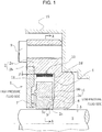
- FIGS. 1 to 3 With reference to FIGS. 1 to 3 , a sealing device according to a first embodiment of the present invention will be described.
- a rotating shaft 3 of a fluid machine is provided extending through a casing 15.
- the left side is the high-pressure fluid side
- the right side is the low-pressure fluid side.
- water, gas, oil, cryogenic fluid, or the like, which is sealed fluid, is sealed in.
- a sealing device 1 mainly includes a floating ring 5 and a housing 2 placing the floating ring 5.
- the housing 2 is mainly formed of a housing body 2a and a cover member 2b.
- the housing body 2a is fixed to the casing 15 by fastening means 9.
- a space 4 defined by a radially inner portion of the housing body 2a and the cover member 2b is formed.
- the cover member 2b is fixed to the housing body 2a by a fastener.
- a radial clearance ⁇ is provided between an inner peripheral surface of the housing 2 and an outer peripheral surface of the rotating shaft 3.
- the floating ring 5 of a hollow cylindrical shape is provided around the outer circumference of the rotating shaft 3.
- the floating ring 5 is formed integrally or separately, depending on its diameter.
- the floating ring 5 has a floating ring body 5a formed of a material with an excellent self-lubricating property such as carbon, and a metallic support ring 5b fitted on the radially outer side of the body 5a, and is formed such that it is not broken even when the floating ring body 5a is brought into contact with the rotating shaft 3 due to the whirling of the rotating shaft 3.
- the diameter and the width of the space 4 in the housing 2 are set to be larger than the outer diameter and the width of the floating ring 5.
- the housing body 2a has an inner surface 2c formed to be in contact with a low-pressure-side side surface 5c of the floating ring body 5a.
- the inner diameter of the floating ring 5 is set to be slightly larger than the outer diameter of the rotating shaft 3, so that the floating ring 5 can move radially in a certain range.
- the radial clearance between the rotating shaft 3 and the floating ring 5 is set to be extremely small to minimize the leakage of the sealed fluid through the clearance.
- a sealing face S is formed at a contact portion between the low-pressure-side side surface 5c of the floating ring body 5a and the inner surface 2c of the housing body 2a opposite the side surface 5c.
- the sealing face S is provided with an introduction recess 6 for introducing the sealed fluid in the space 4 to maintain good lubrication of the sealing face S.
- the floating ring 5 is pressed against the inner surface 2c of the housing body 2a by the sealed fluid at high pressure, preventing leakage between the floating ring 5 and the housing body 2a at the sealing face S.
- a spring 7 may be provided to bias the floating ring 5 toward the inner surface 2c of the housing body 2a.
- the floating ring 5 is provided with a rotation-preventing pin (not shown) extending axially.
- the rotation-preventing pin is loosely fitted into a groove provided in the housing 2, thereby preventing the rotation of the floating ring 5.
- Rotation-preventing means for the floating ring 5 is not limited to the rotation-preventing pin.
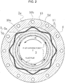
- FIG. 2 is a cross-sectional view taken along line A-A in FIG. 1 , and shows a state where the rotating shaft 3 starts to rotate.
- the present invention provides a sealing device that prevents leakage and also has the effect of reducing the vibration of the rotating shaft 3 by imparting a radial restoring force against the eccentricity of the rotating shaft 3 to restore it to its center position, and a tangential damping force to reduce the whirling of the rotating shaft 3.
- a multi-layered cylindrical body 10 including a plurality of elastically deformable cylindrical thin plates 11 layered on top of each other is provided between the outer peripheral surface of the floating ring 5 and the inner peripheral surface of the housing 1.
- the multi-layered cylindrical body 10 includes the plurality of elastically deformable cylindrical thin plates 11 layered on top of each other.
- the plurality of thin plates 11 can radially move relative to each other, and is held not to axially move relative to each other.
- the multi-layered cylindrical body 10 has a circumferentially corrugated shape.
- the corrugated shape of the multi-layered cylindrical body 10 is set such that, when the rotating shaft 3 is at rest, valleys 10a are in contact with the outer peripheral surface of the floating ring 5, and peaks 10b are in contact with a radially inner peripheral surface 2d of the housing body 2a defining the space 4.
- the width (axial length) of the multi-layered cylindrical body 10 is set to be substantially equal to the width of the floating ring 5.
- the sealed fluid is present on opposite sides of the multi-layered cylindrical body 10.
- the plurality of thin plates 11 constituting the multi-layered cylindrical body 10 is formed of an elastic material, e.g. a metallic material having elasticity.
- a gap ⁇ is provided between the radially adjacent thin plates 11, for allowing the sealed fluid to enter and exit from opposite ends thereof (see FIG. 1 ).
- the gap ⁇ is set to an appropriate size depending on the type of the sealed fluid.
- the thin plates 11 have undulation and surface roughness, only by placing the plurality of thin plates 11 on top of each other, the slight gap ⁇ is formed.
- protrusions may be provided on the surfaces of the thin plates 11, or spacers may be interposed between the adjacent thin plates, to provide the desired gap ⁇ between the adjacent thin plates 11.
- the number of the thin plates 11 is four in the present embodiment, it is not limited to this and may be two or more.
- the pressure generated by the viscous squeeze action is transmitted to the rotating shaft 3 via the floating ring 5, acting as a tangential damping force to reduce the whirling of the rotating shaft 3.
- the space between the outer peripheral surface of the support ring 5b and the inner peripheral surface 2d of the housing body 2a becomes large, so that the gap ⁇ between the plurality of thin plates 11 of the multi-layered cylindrical body 10 becomes large.
- the sealed fluid present outside the multi-layered cylindrical body 10 flows into the gap ⁇ between the thin plates 11 from the ends of the thin plates 11.
- the gap ⁇ is filled with the sealed fluid.
- the sealing device according to the first embodiment of the present invention is as described above, and has the following outstanding advantages:
- the width of the multi-layered cylindrical body 10 is substantially equal to the width of the floating ring 5
- the width of the multi-layered cylindrical body 10 is not limited to this and may be made larger than the width of the floating ring 5 to the extent possible without preventing the axial movement of the floating ring 5, for example.
- the thin plates 11 are formed of a metallic material having elasticity
- the thin plates 11 are not limited to this and may be formed of a synthetic resin material having elasticity.
- the number of the thin plates 11 constituting the multi-layered cylindrical body 10 is four, the number of the thin plates 11 is not limited to this and may be two or more.
- the above embodiment has described the case where protrusions are provided on the surfaces of the thin plates 11 or spacers are interposed between the adjacent thin plates as means for forming the gap ⁇ between the adjacent thin plates 11.
- Protrusions or spacers may be spaced evenly in the circumferential direction and be aligned in the axial direction, for example, to prevent the protrusions or the spacers from obstructing the inflow and outflow of fluid.
- the present invention is applied to the sealing device as the principle purpose, it may be applied to a damping device for damping the vibration of a shaft.
Landscapes
- Engineering & Computer Science (AREA)
- General Engineering & Computer Science (AREA)
- Mechanical Engineering (AREA)
- Sealing Using Fluids, Sealing Without Contact, And Removal Of Oil (AREA)
- Structures Of Non-Positive Displacement Pumps (AREA)
- Sealing Devices (AREA)
Abstract
Description
- The present invention relates to a sealing device suitable for a rotating shaft, and more particularly, relates to a sealing device including a floating ring, which is a noncontact annular seal, suitable for a shaft seal part of a large-sized high-speed rotating machine, or a rotating shaft of a turbopump for a liquid-fuel cryogenic rocket engine, or the like.
- In high-speed rotating equipment such as a cryogenic liquid fuel turbopump for a rocket engine, the shaft vibration of a rotating shaft has frequently presented a problem. Increases in shaft vibration in the manner of self-excited vibration could result in not only the breakdown of the machine but also a serious accident. Thus, techniques for reducing shaft vibration have been studied.
- As a sealing device including a floating ring, for example, one disclosed in
JP 57-154562 A Patent Document 1") is known (hereinafter, referred to as "Conventional Art 1"). InConventional Art 1 disclosed inPatent Document 1, a plurality of leaf springs is provided circumferentially at equal intervals at the outer circumference of an annular floating ring provided around a rotating shaft, the leaf springs are supported on a housing, which is the stationary side, and the floating ring is installed in a floating state by the leaf springs, to dampen the vibration of the floating ring in a direction perpendicular to the axis caused by the vibration of the rotating shaft, and to maintain a constant clearance between the inner peripheral surface of the floating ring and the rotating shaft by the wedge effect generated between the inner peripheral surface of the floating ring and the rotating shaft (the effect of dynamic pressure generated at a wedge portion) and the Lomakin effect (the aligning effect due to inflow losses between the surfaces of the seal ring and the shaft when seal differential pressure develops). - As another sealing device including a floating ring, one disclosed in
JP 2000-310342 A - The sealing device including the floating ring in
Conventional Art 1 can damp the vibration of the floating ring in the direction perpendicular to the axis caused by the vibration of the rotating shaft by the plurality of leaf springs at the outer circumference of the floating ring, but it does not have the technical idea of reducing the vibration of the rotating shaft. - The sealing device including the floating ring in Conventional Art 2 is limited to not preventing the alignment action of the floating ring even when frictional resistance acting between the annular holder and the floating ring increases, and it does not have the technical idea of reducing the vibration of the rotating shaft.
-
- Patent Document 1:
JP 57-154562 A - Patent Document 2:
JP 2000-310342 A - It is an object of the present invention to provide a sealing device including a floating ring around a rotating shaft, which prevents leakage and also has the effect of reducing the vibration of the rotating shaft by, first, imparting a tangential damping force to reduce the whirling of the rotating shaft, and secondly, imparting a radial restoring force against the eccentricity of the rotating shaft to restore it to its center position.
- To attain the above object, a sealing device according to a first aspect of the present invention includes a floating ring in a space between an outer circumference of a rotating shaft and an inner circumference of a housing, and a multi-layered cylindrical body including a plurality of elastically deformable cylindrical thin plates layered on top of each other provided between an outer peripheral surface of the floating ring and an inner peripheral surface of the housing.
- According to this aspect, the sealing device capable of imparting a tangential damping force to reduce the whirling of the rotating shaft to prevent leakage and also have the effect of reducing the vibration of the rotating shaft can be provided.
- According to a second aspect of the present invention, in the sealing device in the first aspect, the multi-layered cylindrical body may be formed in a circumferentially corrugated shape.
- According to this aspect, the sealing device capable of imparting a radial restoring force against the eccentricity of the rotating shaft to restore it to its center position, to prevent leakage and also have the effect of reducing the vibration of the rotating shaft can be provided.
- According to a third aspect of the present invention, in the sealing device in the first or second aspect, the multi-layered cylindrical body may be installed such that sealed fluid is present at opposite ends thereof, and is provided with a gap between the plurality of thin plates for allowing the sealed fluid to enter and exit from opposite ends thereof.
- According to this aspect, pressure generated by the viscous drag of the sealed fluid can be efficiently obtained.
- According to a fourth aspect of the present invention, in the sealing device in any one of the first to third aspects, the corrugated shape of the multi-layered cylindrical body may be set such that, when the rotating shaft is at rest, valleys are in contact with the outer peripheral surface of the floating ring, and peaks are in contact with the inner peripheral surface of the housing.
- According to this aspect, against the eccentricity of the rotating shaft, a radial restoring force to restore it to its center position can be obtained at all times.
- According to a fifth aspect of the present invention, in the sealing device in any one of the first to fourth aspects, the thin plates may be formed of an elastically deformable metallic material.
- According to this aspect, the multi-layered cylindrical body easy to produce and having durability can be obtained.
- The present invention achieves the following outstanding effects:
- (1) The sealing device includes the floating ring in the space between the outer circumference of the rotating shaft and the inner circumference of the housing, and the multi-layered cylindrical body including the plurality of elastically deformable cylindrical thin plates layered on top of each other provided between the outer peripheral surface of the floating ring and the inner peripheral surface of the housing. Consequently, the sealing device capable of imparting a tangential damping force to reduce the whirling of the rotating shaft, to prevent leakage and also have the effect of reducing the vibration of the rotating shaft can be provided.
- (2) The multi-layered cylindrical body is formed in a circumferentially corrugated shape. Consequently, the sealing device capable of imparting a radial restoring force against the eccentricity of the rotating shaft to restore it to its center position, to prevent leakage and also have the effect of reducing the vibration of the rotating shaft can be provided.
- (3) The multi-layered cylindrical body is installed such that the sealed fluid is present at opposite ends thereof, and is provided with a gap between the plurality of thin plates for allowing the sealed fluid to enter and exit from opposite ends thereof. Consequently, pressure generated by the viscous drag of the sealed fluid can be efficiently obtained.
- (4) The corrugated shape of the multi-layered cylindrical body is set such that, when the rotating shaft is at rest, the valleys are in contact with the outer peripheral surface of the floating ring, and the peaks are in contact with the inner peripheral surface of the housing. Consequently, against the eccentricity of the rotating shaft, a radial restoring force to restore it to its center position can be obtained at all times.
- (5) The thin plates are formed of an elastically deformable metallic material. Consequently, the multi-layered cylindrical body easy to produce and having durability can be obtained.
-
-
FIG. 1 is a front cross-sectional view schematically showing a sealing device according to a first embodiment of the present invention. -
FIG. 2 is a cross-sectional view taken along line A-A inFIG. 1 . -
FIG. 3 is a schematic diagram for explaining the effect of reducing the whirling of a rotating shaft in the sealing device according to the first embodiment of the present invention. - Hereinafter, with reference to the drawings, a mode for carrying out this invention will be described illustratively based on an embodiment. However, the dimensions, materials, shapes, relative arrangements, and others of components described in the embodiment are not intended to limit the scope of the present invention only to them unless otherwise explicitly described.
- With reference to
FIGS. 1 to 3 , a sealing device according to a first embodiment of the present invention will be described. - In
FIG. 1 , arotating shaft 3 of a fluid machine is provided extending through acasing 15. The left side is the high-pressure fluid side, and the right side is the low-pressure fluid side. On the high-pressure fluid side, water, gas, oil, cryogenic fluid, or the like, which is sealed fluid, is sealed in. - A
sealing device 1 mainly includes afloating ring 5 and a housing 2 placing thefloating ring 5. - The housing 2 is mainly formed of a
housing body 2a and acover member 2b. Thehousing body 2a is fixed to thecasing 15 by fastening means 9. Aspace 4 defined by a radially inner portion of thehousing body 2a and thecover member 2b is formed. Thecover member 2b is fixed to thehousing body 2a by a fastener. - A radial clearance δ is provided between an inner peripheral surface of the housing 2 and an outer peripheral surface of the rotating
shaft 3. To seal the clearance δ, thefloating ring 5 of a hollow cylindrical shape is provided around the outer circumference of the rotatingshaft 3. Thefloating ring 5 is formed integrally or separately, depending on its diameter. - The floating
ring 5 has a floatingring body 5a formed of a material with an excellent self-lubricating property such as carbon, and ametallic support ring 5b fitted on the radially outer side of thebody 5a, and is formed such that it is not broken even when the floatingring body 5a is brought into contact with the rotatingshaft 3 due to the whirling of the rotatingshaft 3. - The diameter and the width of the
space 4 in the housing 2 are set to be larger than the outer diameter and the width of thefloating ring 5. Thehousing body 2a has aninner surface 2c formed to be in contact with a low-pressure-side side surface 5c of the floatingring body 5a. - The inner diameter of the
floating ring 5 is set to be slightly larger than the outer diameter of the rotatingshaft 3, so that thefloating ring 5 can move radially in a certain range. The radial clearance between the rotatingshaft 3 and the floatingring 5 is set to be extremely small to minimize the leakage of the sealed fluid through the clearance. - A sealing face S is formed at a contact portion between the low-pressure-
side side surface 5c of the floatingring body 5a and theinner surface 2c of thehousing body 2a opposite theside surface 5c. The sealing face S is provided with anintroduction recess 6 for introducing the sealed fluid in thespace 4 to maintain good lubrication of the sealing face S. - The floating
ring 5 is pressed against theinner surface 2c of thehousing body 2a by the sealed fluid at high pressure, preventing leakage between the floatingring 5 and thehousing body 2a at the sealing face S. - A
spring 7 may be provided to bias the floatingring 5 toward theinner surface 2c of thehousing body 2a. - The floating
ring 5 is provided with a rotation-preventing pin (not shown) extending axially. The rotation-preventing pin is loosely fitted into a groove provided in the housing 2, thereby preventing the rotation of the floatingring 5. - Rotation-preventing means for the floating
ring 5 is not limited to the rotation-preventing pin. -
FIG. 2 is a cross-sectional view taken along line A-A inFIG. 1 , and shows a state where therotating shaft 3 starts to rotate. - Now, when the
rotating shaft 3 starts to rotate in a counterclockwise direction, a force to lift the floatingring 5 is generated by the wedge effect at a clearance α caused by the sealed fluid interposed between therotating shaft 3 and the floatingring 5. At this time, if the weight of the floatingring 5 > the force to lift the floatingring 5 generated due to the wedge effect between therotating shaft 3 and the floatingring 5, the center of the floatingring 5 is located below the center of therotating shaft 3. In this state, a fluid film interposed between the outer circumference of therotating shaft 3 and the inner circumference of the floating 5 is locally thinner. Consequently, there is a risk of contact between the inner peripheral surface of the floatingring 5 and the outer peripheral surface of therotating shaft 3 when therotating shaft 3 starts such behavior as whirling. To avoid such a risk, it is necessary to set a large clearance between the inner peripheral surface of the floatingring 5 and the outer peripheral surface of therotating shaft 3. Unfortunately, an increase in the clearance results in an increase in the amount of leakage of the sealed fluid from the clearance in proportion to the third power of the clearance. - The present invention provides a sealing device that prevents leakage and also has the effect of reducing the vibration of the
rotating shaft 3 by imparting a radial restoring force against the eccentricity of therotating shaft 3 to restore it to its center position, and a tangential damping force to reduce the whirling of therotating shaft 3. For that purpose, as shown inFIGS. 1 and2 , a multi-layeredcylindrical body 10 including a plurality of elastically deformable cylindricalthin plates 11 layered on top of each other is provided between the outer peripheral surface of the floatingring 5 and the inner peripheral surface of thehousing 1. - As shown in
FIGS. 1 and2 , the multi-layeredcylindrical body 10 includes the plurality of elastically deformable cylindricalthin plates 11 layered on top of each other. The plurality ofthin plates 11 can radially move relative to each other, and is held not to axially move relative to each other. - The multi-layered
cylindrical body 10 has a circumferentially corrugated shape. - The corrugated shape of the multi-layered
cylindrical body 10 is set such that, when therotating shaft 3 is at rest,valleys 10a are in contact with the outer peripheral surface of the floatingring 5, and peaks 10b are in contact with a radially innerperipheral surface 2d of thehousing body 2a defining thespace 4. - Thus, when the
rotating shaft 3 is decentered, a radial restoring force to push therotating shaft 3 back to its center position acts due to the leaf spring action of the multi-layeredcylindrical body 10, so that therotating shaft 3 can be pushed back to its center position. Consequently, the sealing face S between theside surface 5c of the floatingring 5 and the side surface 4a of thehousing 1 can be maintained in a normal state to maintain the sealing effect. - As shown in
FIG. 1 , the width (axial length) of the multi-layeredcylindrical body 10 is set to be substantially equal to the width of the floatingring 5. The sealed fluid is present on opposite sides of the multi-layeredcylindrical body 10. - The plurality of
thin plates 11 constituting the multi-layeredcylindrical body 10 is formed of an elastic material, e.g. a metallic material having elasticity. A gap β is provided between the radially adjacentthin plates 11, for allowing the sealed fluid to enter and exit from opposite ends thereof (seeFIG. 1 ). The gap β is set to an appropriate size depending on the type of the sealed fluid. When thethin plates 11 have undulation and surface roughness, only by placing the plurality ofthin plates 11 on top of each other, the slight gap β is formed. Thus, there is no need to provide special means to form the gap β between the adjacentthin plates 11. However, if necessary, protrusions may be provided on the surfaces of thethin plates 11, or spacers may be interposed between the adjacent thin plates, to provide the desired gap β between the adjacentthin plates 11. - Although the number of the
thin plates 11 is four in the present embodiment, it is not limited to this and may be two or more. - Next, with reference to
FIG. 3 , in the sealing device according to the present invention, the effect of reducing the whirling of therotating shaft 3 when it whirls with a certain period in a state decentered from its center will be described. - Assume a state where the
rotating shaft 3 is decentered to the upper right from its center as shown inFIG. 3 in a whirling state of therotating shaft 3. The floatingring 5 is pressed by therotating shaft 3 and moves to the upper-right or radially outwards. When the floatingring 5 moves to the upper-right or radially outwards, an upper right portion of the multi-layeredcylindrical body 10 is compressed. The gap β between the plurality ofthin plates 11 of the multi-layeredcylindrical body 10 becomes smaller at the compressed portion, causing the sealed fluid present in the gap β to flow out from the ends to the outside of thethin plates 11. During the flowing out of the sealed fluid, pressure is generated due to the viscous drag of the sealed fluid (damper) (in the present description, sometimes referred to as a viscous squeeze action). - The pressure generated by the viscous squeeze action is transmitted to the
rotating shaft 3 via the floatingring 5, acting as a tangential damping force to reduce the whirling of therotating shaft 3. - On the other hand, at the lower left opposite to the movement direction of the floating
ring 5, the space between the outer peripheral surface of thesupport ring 5b and the innerperipheral surface 2d of thehousing body 2a becomes large, so that the gap β between the plurality ofthin plates 11 of the multi-layeredcylindrical body 10 becomes large. The sealed fluid present outside the multi-layeredcylindrical body 10 flows into the gap β between thethin plates 11 from the ends of thethin plates 11. The gap β is filled with the sealed fluid. - To increase pressure generated by the viscous squeeze action, it is necessary to increase the total amount of viscous drag during the flowing out of the sealed fluid. By increasing the number of the
thin plates 11, the total amount of viscous drag can be increased. - The sealing device according to the first embodiment of the present invention is as described above, and has the following outstanding advantages:
- (1) In the sealing device including the floating
ring 5 in thespace 4 between the outer circumference of therotating shaft 3 and the inner circumference of thehousing 1, the multi-layeredcylindrical body 10 including the plurality of elastically deformable cylindricalthin plates 11 layered on top of each other is provided between the outer peripheral surface of the floatingring 5 and the inner peripheral surface of thehousing 1. Consequently, the sealing device capable of imparting a tangential damping force to reduce the whirling of the rotating shaft, to prevent leakage and also have the effect of reducing the vibration of the rotating shaft can be provided. - (2) The multi-layered
cylindrical body 10 is formed in the circumferentially corrugated shape. Consequently, the sealing device capable of imparting a radial restoring force against the eccentricity of the rotating shaft to restore it to its center position, to prevent leakage and also have the effect of reducing the vibration of the rotating shaft can be provided. - (3) The multi-layered
cylindrical body 10 is installed such that the sealed fluid is present at opposite ends thereof. Between the plurality ofthin plates 11, the gap β for allowing the sealed fluid to enter and exit from opposite ends thereof is provided. Consequently, pressure generated by the viscous drag of the sealed fluid can be efficiently obtained. - (4) The corrugated shape of the multi-layered
cylindrical body 10 is set such that, when therotating shaft 3 is at rest, thevalleys 10a are in contact with the outer peripheral surface of the floatingring 5, and thepeaks 10b are in contact with the innerperipheral surface 2d of the housing. Consequently, against the eccentricity of therotating shaft 3, a radial restoring force to restore it to its center position can be obtained at all times. - (5) The
thin plates 11 are formed of an elastically deformable metallic material. Consequently, the multi-layeredcylindrical body 10 easy to produce and having durability can be obtained. - Although the embodiment of the present invention has been described above with reference to the drawings, its specific configuration is not limited to the embodiment. Any changes and additions made without departing from the scope of the present invention are included in the present invention.
- For example, although the above embodiment has described the case where the width of the multi-layered
cylindrical body 10 is substantially equal to the width of the floatingring 5, the width of the multi-layeredcylindrical body 10 is not limited to this and may be made larger than the width of the floatingring 5 to the extent possible without preventing the axial movement of the floatingring 5, for example. - Further, for example, although the above embodiment has described the case where the
thin plates 11 are formed of a metallic material having elasticity, thethin plates 11 are not limited to this and may be formed of a synthetic resin material having elasticity. - Further, for example, although the above embodiment has described the case where the number of the
thin plates 11 constituting the multi-layeredcylindrical body 10 is four, the number of thethin plates 11 is not limited to this and may be two or more. - Further, for example, the above embodiment has described the case where protrusions are provided on the surfaces of the
thin plates 11 or spacers are interposed between the adjacent thin plates as means for forming the gap β between the adjacentthin plates 11. Protrusions or spacers may be spaced evenly in the circumferential direction and be aligned in the axial direction, for example, to prevent the protrusions or the spacers from obstructing the inflow and outflow of fluid. - Although the present invention is applied to the sealing device as the principle purpose, it may be applied to a damping device for damping the vibration of a shaft.
-
- 1 sealing device
- 2 housing
- 2a housing body
- 2b cover member
- 2c inner surface
- 2d inner peripheral surface
- 3 rotating shaft
- 4 space
- 5 floating ring
- 5a floating ring body
- 5b support ring
- 5c low-pressure-side side surface
- 6 introduction recess
- 7 spring
- 9 fastener
- 10 multi-layered cylindrical body
- 10a valley
- 10b peak
- 11 thin plate
- 15 casing
- S sealing face
- δ clearance between inner peripheral surface of housing and outer peripheral surface of rotating shaft
- α clearance between rotating shaft and floating ring
- β gap between thin plates
Claims (5)
- A sealing device comprising: a floating ring in a space between an outer circumference of a rotating shaft and an inner circumference of a housing; and a multi-layered cylindrical body including a plurality of elastically deformable cylindrical thin plates layered on top of each other provided between an outer peripheral surface of the floating ring and an inner peripheral surface of the housing.
- The sealing device according to claim 1, wherein the multi-layered cylindrical body is formed in a circumferentially corrugated shape.
- The sealing device according to claim 1 or 2, wherein the multi-layered cylindrical body is provided such that sealed fluid is present at opposite ends thereof, and is provided with a gap between the plurality of thin plates for allowing the sealed fluid to enter and exit from opposite ends thereof.
- The sealing device according to any one of claims 1 to 3, wherein the corrugated shape of the multi-layered cylindrical body is set such that, when the rotating shaft is at rest, valleys are in contact with the outer peripheral surface of the floating ring, and peaks are in contact with the inner peripheral surface of the housing.
- The sealing device according to any one of claims 1 to 4, wherein the thin plates are formed of an elastically deformable metallic material.
Applications Claiming Priority (2)
| Application Number | Priority Date | Filing Date | Title |
|---|---|---|---|
| JP2017031200 | 2017-02-22 | ||
| PCT/JP2018/005371 WO2018155315A1 (en) | 2017-02-22 | 2018-02-16 | Seal device |
Publications (3)
| Publication Number | Publication Date |
|---|---|
| EP3587869A1 true EP3587869A1 (en) | 2020-01-01 |
| EP3587869A4 EP3587869A4 (en) | 2020-12-09 |
| EP3587869B1 EP3587869B1 (en) | 2023-04-05 |
Family
ID=63252667
Family Applications (1)
| Application Number | Title | Priority Date | Filing Date |
|---|---|---|---|
| EP18757911.5A Active EP3587869B1 (en) | 2017-02-22 | 2018-02-16 | Seal device |
Country Status (4)
| Country | Link |
|---|---|
| US (1) | US11085539B2 (en) |
| EP (1) | EP3587869B1 (en) |
| JP (1) | JP6952759B2 (en) |
| WO (1) | WO2018155315A1 (en) |
Families Citing this family (2)
| Publication number | Priority date | Publication date | Assignee | Title |
|---|---|---|---|---|
| CN110553847B (en) * | 2019-09-25 | 2024-07-12 | 泸州卓远液压有限公司 | Buoyancy type thrust adapter |
| CN112648378A (en) * | 2021-02-02 | 2021-04-13 | 昆明理工大学 | Cylindrical surface air film seal of bubbling type foil flexible support |
Family Cites Families (12)
| Publication number | Priority date | Publication date | Assignee | Title |
|---|---|---|---|---|
| US2964339A (en) * | 1955-01-26 | 1960-12-13 | Macks Elmer Fred | Seal |
| US3333855A (en) * | 1964-09-22 | 1967-08-01 | Gits Bros Mfg Co | Floating controlled gap seal |
| CH540446A (en) * | 1971-07-09 | 1973-08-15 | Bbc Sulzer Turbomaschinen | Stop sleeve for rotating shafts |
| DE2934271C2 (en) * | 1979-08-24 | 1983-11-10 | MTU Motoren- und Turbinen-Union München GmbH, 8000 München | Aerodynamic radial bearing for high-speed flow machines |
| JPS57154562A (en) | 1981-03-13 | 1982-09-24 | Hitachi Ltd | Floating seal |
| US5603574A (en) * | 1987-05-29 | 1997-02-18 | Kmc, Inc. | Fluid dampened support having variable stiffness and damping |
| US5014999A (en) * | 1989-03-06 | 1991-05-14 | Car-Graph, Inc. | Pressure enhanced self aligning seal |
| JPH10196800A (en) * | 1997-01-08 | 1998-07-31 | Mitsubishi Heavy Ind Ltd | Shaft sealing device |
| JP3912926B2 (en) | 1999-04-27 | 2007-05-09 | 三菱重工業株式会社 | Floating machine floating seal |
| CA2581508A1 (en) * | 2004-10-22 | 2006-04-27 | Burckhardt Compression Ag | Dry-running piston rod sealing arrangement, and method for sealing a piston rod using one such arrangement |
| JP5286955B2 (en) * | 2008-06-12 | 2013-09-11 | 株式会社Ihi | Foil bearing |
| KR101558490B1 (en) * | 2015-03-20 | 2015-10-07 | ㈜티앤이코리아 | Journal Foil Air Bearing |
-
2018
- 2018-02-16 EP EP18757911.5A patent/EP3587869B1/en active Active
- 2018-02-16 WO PCT/JP2018/005371 patent/WO2018155315A1/en not_active Ceased
- 2018-02-16 JP JP2019501275A patent/JP6952759B2/en active Active
- 2018-02-16 US US16/488,097 patent/US11085539B2/en active Active
Also Published As
| Publication number | Publication date |
|---|---|
| US20200063871A1 (en) | 2020-02-27 |
| US11085539B2 (en) | 2021-08-10 |
| EP3587869B1 (en) | 2023-04-05 |
| JPWO2018155315A1 (en) | 2019-12-12 |
| JP6952759B2 (en) | 2021-10-20 |
| WO2018155315A1 (en) | 2018-08-30 |
| EP3587869A4 (en) | 2020-12-09 |
Similar Documents
| Publication | Publication Date | Title |
|---|---|---|
| EP3163133B1 (en) | Sliding component | |
| JP6861730B2 (en) | Sliding parts | |
| EP3587872B1 (en) | Seal device | |
| US9638326B2 (en) | Arch-bound ring seal and ring seal system including an arch-bound ring seal | |
| KR970001606B1 (en) | Transverse Vibration Isolator Using Leaf Springs | |
| CN100416142C (en) | Seals for rotating parts | |
| US8100403B2 (en) | Hydrodynamic intershaft seal and assembly | |
| KR102459648B1 (en) | sliding parts | |
| KR20200008160A (en) | Sliding member | |
| KR102346395B1 (en) | sliding parts | |
| EP2287479A1 (en) | Foil bearing | |
| EP3587869B1 (en) | Seal device | |
| KR20210148329A (en) | sliding parts | |
| KR102346413B1 (en) | sliding parts | |
| US20200011425A1 (en) | Seal device | |
| KR101967084B1 (en) | Sealing device and turbine for turbine, and thin plate for sealing device | |
| JP7592728B2 (en) | Sealing device | |
| KR101988785B1 (en) | Turbine sealing devices and turbines, and thin plates for sealing devices | |
| KR102852341B1 (en) | seal device | |
| JP7350448B2 (en) | mechanical seal | |
| KR101898830B1 (en) | Shaft sealing mechanism | |
| JP7350447B2 (en) | mechanical seal | |
| JP7350449B2 (en) | mechanical seal |
Legal Events
| Date | Code | Title | Description |
|---|---|---|---|
| STAA | Information on the status of an ep patent application or granted ep patent |
Free format text: STATUS: THE INTERNATIONAL PUBLICATION HAS BEEN MADE |
|
| PUAI | Public reference made under article 153(3) epc to a published international application that has entered the european phase |
Free format text: ORIGINAL CODE: 0009012 |
|
| STAA | Information on the status of an ep patent application or granted ep patent |
Free format text: STATUS: REQUEST FOR EXAMINATION WAS MADE |
|
| 17P | Request for examination filed |
Effective date: 20190822 |
|
| AK | Designated contracting states |
Kind code of ref document: A1 Designated state(s): AL AT BE BG CH CY CZ DE DK EE ES FI FR GB GR HR HU IE IS IT LI LT LU LV MC MK MT NL NO PL PT RO RS SE SI SK SM TR |
|
| AX | Request for extension of the european patent |
Extension state: BA ME |
|
| DAV | Request for validation of the european patent (deleted) | ||
| DAX | Request for extension of the european patent (deleted) | ||
| A4 | Supplementary search report drawn up and despatched |
Effective date: 20201105 |
|
| RIC1 | Information provided on ipc code assigned before grant |
Ipc: F04D 29/12 20060101ALI20201030BHEP Ipc: F16J 15/44 20060101ALI20201030BHEP Ipc: F16J 15/40 20060101AFI20201030BHEP Ipc: F16C 17/02 20060101ALI20201030BHEP Ipc: F16J 15/26 20060101ALI20201030BHEP |
|
| GRAP | Despatch of communication of intention to grant a patent |
Free format text: ORIGINAL CODE: EPIDOSNIGR1 |
|
| STAA | Information on the status of an ep patent application or granted ep patent |
Free format text: STATUS: GRANT OF PATENT IS INTENDED |
|
| INTG | Intention to grant announced |
Effective date: 20221027 |
|
| RIN1 | Information on inventor provided before grant (corrected) |
Inventor name: KIKUCHI, RYU Inventor name: KUROKI, YASUHIRO Inventor name: HIROMATSU, JUN Inventor name: KASAHARA, HIDETOSHI Inventor name: IGUCHI, TETSUYA Inventor name: KIMURA, WATARU Inventor name: INOUE, HIDEYUKI Inventor name: TOKUNAGA, YUICHIRO |
|
| GRAS | Grant fee paid |
Free format text: ORIGINAL CODE: EPIDOSNIGR3 |
|
| GRAA | (expected) grant |
Free format text: ORIGINAL CODE: 0009210 |
|
| STAA | Information on the status of an ep patent application or granted ep patent |
Free format text: STATUS: THE PATENT HAS BEEN GRANTED |
|
| AK | Designated contracting states |
Kind code of ref document: B1 Designated state(s): AL AT BE BG CH CY CZ DE DK EE ES FI FR GB GR HR HU IE IS IT LI LT LU LV MC MK MT NL NO PL PT RO RS SE SI SK SM TR |
|
| REG | Reference to a national code |
Ref country code: GB Ref legal event code: FG4D |
|
| REG | Reference to a national code |
Ref country code: DE Ref legal event code: R096 Ref document number: 602018048073 Country of ref document: DE |
|
| REG | Reference to a national code |
Ref country code: CH Ref legal event code: EP |
|
| REG | Reference to a national code |
Ref country code: AT Ref legal event code: REF Ref document number: 1558459 Country of ref document: AT Kind code of ref document: T Effective date: 20230415 |
|
| REG | Reference to a national code |
Ref country code: IE Ref legal event code: FG4D |
|
| REG | Reference to a national code |
Ref country code: LT Ref legal event code: MG9D |
|
| REG | Reference to a national code |
Ref country code: NL Ref legal event code: MP Effective date: 20230405 |
|
| REG | Reference to a national code |
Ref country code: AT Ref legal event code: MK05 Ref document number: 1558459 Country of ref document: AT Kind code of ref document: T Effective date: 20230405 |
|
| PG25 | Lapsed in a contracting state [announced via postgrant information from national office to epo] |
Ref country code: NL Free format text: LAPSE BECAUSE OF FAILURE TO SUBMIT A TRANSLATION OF THE DESCRIPTION OR TO PAY THE FEE WITHIN THE PRESCRIBED TIME-LIMIT Effective date: 20230405 |
|
| PG25 | Lapsed in a contracting state [announced via postgrant information from national office to epo] |
Ref country code: SE Free format text: LAPSE BECAUSE OF FAILURE TO SUBMIT A TRANSLATION OF THE DESCRIPTION OR TO PAY THE FEE WITHIN THE PRESCRIBED TIME-LIMIT Effective date: 20230405 Ref country code: PT Free format text: LAPSE BECAUSE OF FAILURE TO SUBMIT A TRANSLATION OF THE DESCRIPTION OR TO PAY THE FEE WITHIN THE PRESCRIBED TIME-LIMIT Effective date: 20230807 Ref country code: NO Free format text: LAPSE BECAUSE OF FAILURE TO SUBMIT A TRANSLATION OF THE DESCRIPTION OR TO PAY THE FEE WITHIN THE PRESCRIBED TIME-LIMIT Effective date: 20230705 Ref country code: ES Free format text: LAPSE BECAUSE OF FAILURE TO SUBMIT A TRANSLATION OF THE DESCRIPTION OR TO PAY THE FEE WITHIN THE PRESCRIBED TIME-LIMIT Effective date: 20230405 Ref country code: AT Free format text: LAPSE BECAUSE OF FAILURE TO SUBMIT A TRANSLATION OF THE DESCRIPTION OR TO PAY THE FEE WITHIN THE PRESCRIBED TIME-LIMIT Effective date: 20230405 |
|
| PG25 | Lapsed in a contracting state [announced via postgrant information from national office to epo] |
Ref country code: RS Free format text: LAPSE BECAUSE OF FAILURE TO SUBMIT A TRANSLATION OF THE DESCRIPTION OR TO PAY THE FEE WITHIN THE PRESCRIBED TIME-LIMIT Effective date: 20230405 Ref country code: PL Free format text: LAPSE BECAUSE OF FAILURE TO SUBMIT A TRANSLATION OF THE DESCRIPTION OR TO PAY THE FEE WITHIN THE PRESCRIBED TIME-LIMIT Effective date: 20230405 Ref country code: LV Free format text: LAPSE BECAUSE OF FAILURE TO SUBMIT A TRANSLATION OF THE DESCRIPTION OR TO PAY THE FEE WITHIN THE PRESCRIBED TIME-LIMIT Effective date: 20230405 Ref country code: LT Free format text: LAPSE BECAUSE OF FAILURE TO SUBMIT A TRANSLATION OF THE DESCRIPTION OR TO PAY THE FEE WITHIN THE PRESCRIBED TIME-LIMIT Effective date: 20230405 Ref country code: IS Free format text: LAPSE BECAUSE OF FAILURE TO SUBMIT A TRANSLATION OF THE DESCRIPTION OR TO PAY THE FEE WITHIN THE PRESCRIBED TIME-LIMIT Effective date: 20230805 Ref country code: HR Free format text: LAPSE BECAUSE OF FAILURE TO SUBMIT A TRANSLATION OF THE DESCRIPTION OR TO PAY THE FEE WITHIN THE PRESCRIBED TIME-LIMIT Effective date: 20230405 Ref country code: GR Free format text: LAPSE BECAUSE OF FAILURE TO SUBMIT A TRANSLATION OF THE DESCRIPTION OR TO PAY THE FEE WITHIN THE PRESCRIBED TIME-LIMIT Effective date: 20230706 Ref country code: AL Free format text: LAPSE BECAUSE OF FAILURE TO SUBMIT A TRANSLATION OF THE DESCRIPTION OR TO PAY THE FEE WITHIN THE PRESCRIBED TIME-LIMIT Effective date: 20230405 |
|
| PG25 | Lapsed in a contracting state [announced via postgrant information from national office to epo] |
Ref country code: FI Free format text: LAPSE BECAUSE OF FAILURE TO SUBMIT A TRANSLATION OF THE DESCRIPTION OR TO PAY THE FEE WITHIN THE PRESCRIBED TIME-LIMIT Effective date: 20230405 |
|
| REG | Reference to a national code |
Ref country code: DE Ref legal event code: R097 Ref document number: 602018048073 Country of ref document: DE |
|
| PG25 | Lapsed in a contracting state [announced via postgrant information from national office to epo] |
Ref country code: SK Free format text: LAPSE BECAUSE OF FAILURE TO SUBMIT A TRANSLATION OF THE DESCRIPTION OR TO PAY THE FEE WITHIN THE PRESCRIBED TIME-LIMIT Effective date: 20230405 |
|
| PG25 | Lapsed in a contracting state [announced via postgrant information from national office to epo] |
Ref country code: SM Free format text: LAPSE BECAUSE OF FAILURE TO SUBMIT A TRANSLATION OF THE DESCRIPTION OR TO PAY THE FEE WITHIN THE PRESCRIBED TIME-LIMIT Effective date: 20230405 Ref country code: SK Free format text: LAPSE BECAUSE OF FAILURE TO SUBMIT A TRANSLATION OF THE DESCRIPTION OR TO PAY THE FEE WITHIN THE PRESCRIBED TIME-LIMIT Effective date: 20230405 Ref country code: RO Free format text: LAPSE BECAUSE OF FAILURE TO SUBMIT A TRANSLATION OF THE DESCRIPTION OR TO PAY THE FEE WITHIN THE PRESCRIBED TIME-LIMIT Effective date: 20230405 Ref country code: EE Free format text: LAPSE BECAUSE OF FAILURE TO SUBMIT A TRANSLATION OF THE DESCRIPTION OR TO PAY THE FEE WITHIN THE PRESCRIBED TIME-LIMIT Effective date: 20230405 Ref country code: DK Free format text: LAPSE BECAUSE OF FAILURE TO SUBMIT A TRANSLATION OF THE DESCRIPTION OR TO PAY THE FEE WITHIN THE PRESCRIBED TIME-LIMIT Effective date: 20230405 Ref country code: CZ Free format text: LAPSE BECAUSE OF FAILURE TO SUBMIT A TRANSLATION OF THE DESCRIPTION OR TO PAY THE FEE WITHIN THE PRESCRIBED TIME-LIMIT Effective date: 20230405 |
|
| PLBE | No opposition filed within time limit |
Free format text: ORIGINAL CODE: 0009261 |
|
| STAA | Information on the status of an ep patent application or granted ep patent |
Free format text: STATUS: NO OPPOSITION FILED WITHIN TIME LIMIT |
|
| 26N | No opposition filed |
Effective date: 20240108 |
|
| PG25 | Lapsed in a contracting state [announced via postgrant information from national office to epo] |
Ref country code: SI Free format text: LAPSE BECAUSE OF FAILURE TO SUBMIT A TRANSLATION OF THE DESCRIPTION OR TO PAY THE FEE WITHIN THE PRESCRIBED TIME-LIMIT Effective date: 20230405 |
|
| PG25 | Lapsed in a contracting state [announced via postgrant information from national office to epo] |
Ref country code: SI Free format text: LAPSE BECAUSE OF FAILURE TO SUBMIT A TRANSLATION OF THE DESCRIPTION OR TO PAY THE FEE WITHIN THE PRESCRIBED TIME-LIMIT Effective date: 20230405 |
|
| REG | Reference to a national code |
Ref country code: DE Ref legal event code: R119 Ref document number: 602018048073 Country of ref document: DE |
|
| PG25 | Lapsed in a contracting state [announced via postgrant information from national office to epo] |
Ref country code: MC Free format text: LAPSE BECAUSE OF FAILURE TO SUBMIT A TRANSLATION OF THE DESCRIPTION OR TO PAY THE FEE WITHIN THE PRESCRIBED TIME-LIMIT Effective date: 20230405 |
|
| REG | Reference to a national code |
Ref country code: CH Ref legal event code: PL |
|
| PG25 | Lapsed in a contracting state [announced via postgrant information from national office to epo] |
Ref country code: LU Free format text: LAPSE BECAUSE OF NON-PAYMENT OF DUE FEES Effective date: 20240216 |
|
| PG25 | Lapsed in a contracting state [announced via postgrant information from national office to epo] |
Ref country code: CH Free format text: LAPSE BECAUSE OF NON-PAYMENT OF DUE FEES Effective date: 20240229 |
|
| PG25 | Lapsed in a contracting state [announced via postgrant information from national office to epo] |
Ref country code: LU Free format text: LAPSE BECAUSE OF NON-PAYMENT OF DUE FEES Effective date: 20240216 Ref country code: CH Free format text: LAPSE BECAUSE OF NON-PAYMENT OF DUE FEES Effective date: 20240229 |
|
| PG25 | Lapsed in a contracting state [announced via postgrant information from national office to epo] |
Ref country code: BG Free format text: LAPSE BECAUSE OF FAILURE TO SUBMIT A TRANSLATION OF THE DESCRIPTION OR TO PAY THE FEE WITHIN THE PRESCRIBED TIME-LIMIT Effective date: 20230405 |
|
| PG25 | Lapsed in a contracting state [announced via postgrant information from national office to epo] |
Ref country code: BG Free format text: LAPSE BECAUSE OF FAILURE TO SUBMIT A TRANSLATION OF THE DESCRIPTION OR TO PAY THE FEE WITHIN THE PRESCRIBED TIME-LIMIT Effective date: 20230405 |
|
| REG | Reference to a national code |
Ref country code: BE Ref legal event code: MM Effective date: 20240229 |
|
| PG25 | Lapsed in a contracting state [announced via postgrant information from national office to epo] |
Ref country code: DE Free format text: LAPSE BECAUSE OF NON-PAYMENT OF DUE FEES Effective date: 20240903 |
|
| PG25 | Lapsed in a contracting state [announced via postgrant information from national office to epo] |
Ref country code: BE Free format text: LAPSE BECAUSE OF NON-PAYMENT OF DUE FEES Effective date: 20240229 |
|
| PG25 | Lapsed in a contracting state [announced via postgrant information from national office to epo] |
Ref country code: IE Free format text: LAPSE BECAUSE OF NON-PAYMENT OF DUE FEES Effective date: 20240216 |
|
| PG25 | Lapsed in a contracting state [announced via postgrant information from national office to epo] |
Ref country code: IE Free format text: LAPSE BECAUSE OF NON-PAYMENT OF DUE FEES Effective date: 20240216 Ref country code: DE Free format text: LAPSE BECAUSE OF NON-PAYMENT OF DUE FEES Effective date: 20240903 Ref country code: BE Free format text: LAPSE BECAUSE OF NON-PAYMENT OF DUE FEES Effective date: 20240229 |
|
| PG25 | Lapsed in a contracting state [announced via postgrant information from national office to epo] |
Ref country code: CY Free format text: LAPSE BECAUSE OF FAILURE TO SUBMIT A TRANSLATION OF THE DESCRIPTION OR TO PAY THE FEE WITHIN THE PRESCRIBED TIME-LIMIT; INVALID AB INITIO Effective date: 20180216 |
|
| PG25 | Lapsed in a contracting state [announced via postgrant information from national office to epo] |
Ref country code: HU Free format text: LAPSE BECAUSE OF FAILURE TO SUBMIT A TRANSLATION OF THE DESCRIPTION OR TO PAY THE FEE WITHIN THE PRESCRIBED TIME-LIMIT; INVALID AB INITIO Effective date: 20180216 |
|
| PG25 | Lapsed in a contracting state [announced via postgrant information from national office to epo] |
Ref country code: TR Free format text: LAPSE BECAUSE OF FAILURE TO SUBMIT A TRANSLATION OF THE DESCRIPTION OR TO PAY THE FEE WITHIN THE PRESCRIBED TIME-LIMIT Effective date: 20230405 |
|
| PGFP | Annual fee paid to national office [announced via postgrant information from national office to epo] |
Ref country code: FR Payment date: 20251231 Year of fee payment: 9 |
|
| PGFP | Annual fee paid to national office [announced via postgrant information from national office to epo] |
Ref country code: GB Payment date: 20260106 Year of fee payment: 9 |
|
| PGFP | Annual fee paid to national office [announced via postgrant information from national office to epo] |
Ref country code: IT Payment date: 20260122 Year of fee payment: 9 |