EP3587816A1 - Compressor having terminal protection structure - Google Patents
Compressor having terminal protection structure Download PDFInfo
- Publication number
- EP3587816A1 EP3587816A1 EP18787893.9A EP18787893A EP3587816A1 EP 3587816 A1 EP3587816 A1 EP 3587816A1 EP 18787893 A EP18787893 A EP 18787893A EP 3587816 A1 EP3587816 A1 EP 3587816A1
- Authority
- EP
- European Patent Office
- Prior art keywords
- cover
- compressor according
- opening
- opening side
- terminal
- Prior art date
- Legal status (The legal status is an assumption and is not a legal conclusion. Google has not performed a legal analysis and makes no representation as to the accuracy of the status listed.)
- Granted
Links
Images




Classifications
-
- F—MECHANICAL ENGINEERING; LIGHTING; HEATING; WEAPONS; BLASTING
- F04—POSITIVE - DISPLACEMENT MACHINES FOR LIQUIDS; PUMPS FOR LIQUIDS OR ELASTIC FLUIDS
- F04B—POSITIVE-DISPLACEMENT MACHINES FOR LIQUIDS; PUMPS
- F04B35/00—Piston pumps specially adapted for elastic fluids and characterised by the driving means to their working members, or by combination with, or adaptation to, specific driving engines or motors, not otherwise provided for
- F04B35/04—Piston pumps specially adapted for elastic fluids and characterised by the driving means to their working members, or by combination with, or adaptation to, specific driving engines or motors, not otherwise provided for the means being electric
-
- F—MECHANICAL ENGINEERING; LIGHTING; HEATING; WEAPONS; BLASTING
- F04—POSITIVE - DISPLACEMENT MACHINES FOR LIQUIDS; PUMPS FOR LIQUIDS OR ELASTIC FLUIDS
- F04C—ROTARY-PISTON, OR OSCILLATING-PISTON, POSITIVE-DISPLACEMENT MACHINES FOR LIQUIDS; ROTARY-PISTON, OR OSCILLATING-PISTON, POSITIVE-DISPLACEMENT PUMPS
- F04C14/00—Control of, monitoring of, or safety arrangements for, machines, pumps or pumping installations
- F04C14/28—Safety arrangements; Monitoring
-
- F—MECHANICAL ENGINEERING; LIGHTING; HEATING; WEAPONS; BLASTING
- F04—POSITIVE - DISPLACEMENT MACHINES FOR LIQUIDS; PUMPS FOR LIQUIDS OR ELASTIC FLUIDS
- F04B—POSITIVE-DISPLACEMENT MACHINES FOR LIQUIDS; PUMPS
- F04B39/00—Component parts, details, or accessories, of pumps or pumping systems specially adapted for elastic fluids, not otherwise provided for in, or of interest apart from, groups F04B25/00 - F04B37/00
-
- F—MECHANICAL ENGINEERING; LIGHTING; HEATING; WEAPONS; BLASTING
- F04—POSITIVE - DISPLACEMENT MACHINES FOR LIQUIDS; PUMPS FOR LIQUIDS OR ELASTIC FLUIDS
- F04B—POSITIVE-DISPLACEMENT MACHINES FOR LIQUIDS; PUMPS
- F04B39/00—Component parts, details, or accessories, of pumps or pumping systems specially adapted for elastic fluids, not otherwise provided for in, or of interest apart from, groups F04B25/00 - F04B37/00
- F04B39/12—Casings; Cylinders; Cylinder heads; Fluid connections
- F04B39/121—Casings
-
- F—MECHANICAL ENGINEERING; LIGHTING; HEATING; WEAPONS; BLASTING
- F25—REFRIGERATION OR COOLING; COMBINED HEATING AND REFRIGERATION SYSTEMS; HEAT PUMP SYSTEMS; MANUFACTURE OR STORAGE OF ICE; LIQUEFACTION SOLIDIFICATION OF GASES
- F25B—REFRIGERATION MACHINES, PLANTS OR SYSTEMS; COMBINED HEATING AND REFRIGERATION SYSTEMS; HEAT PUMP SYSTEMS
- F25B31/00—Compressor arrangements
- F25B31/02—Compressor arrangements of motor-compressor units
- F25B31/026—Compressor arrangements of motor-compressor units with compressor of rotary type
-
- F—MECHANICAL ENGINEERING; LIGHTING; HEATING; WEAPONS; BLASTING
- F25—REFRIGERATION OR COOLING; COMBINED HEATING AND REFRIGERATION SYSTEMS; HEAT PUMP SYSTEMS; MANUFACTURE OR STORAGE OF ICE; LIQUEFACTION SOLIDIFICATION OF GASES
- F25B—REFRIGERATION MACHINES, PLANTS OR SYSTEMS; COMBINED HEATING AND REFRIGERATION SYSTEMS; HEAT PUMP SYSTEMS
- F25B49/00—Arrangement or mounting of control or safety devices
- F25B49/02—Arrangement or mounting of control or safety devices for compression type machines, plants or systems
-
- H—ELECTRICITY
- H02—GENERATION; CONVERSION OR DISTRIBUTION OF ELECTRIC POWER
- H02K—DYNAMO-ELECTRIC MACHINES
- H02K5/00—Casings; Enclosures; Supports
- H02K5/04—Casings or enclosures characterised by the shape, form or construction thereof
- H02K5/22—Auxiliary parts of casings not covered by groups H02K5/06-H02K5/20, e.g. shaped to form connection boxes or terminal boxes
-
- H—ELECTRICITY
- H02—GENERATION; CONVERSION OR DISTRIBUTION OF ELECTRIC POWER
- H02K—DYNAMO-ELECTRIC MACHINES
- H02K5/00—Casings; Enclosures; Supports
- H02K5/04—Casings or enclosures characterised by the shape, form or construction thereof
- H02K5/22—Auxiliary parts of casings not covered by groups H02K5/06-H02K5/20, e.g. shaped to form connection boxes or terminal boxes
- H02K5/225—Terminal boxes or connection arrangements
-
- F—MECHANICAL ENGINEERING; LIGHTING; HEATING; WEAPONS; BLASTING
- F04—POSITIVE - DISPLACEMENT MACHINES FOR LIQUIDS; PUMPS FOR LIQUIDS OR ELASTIC FLUIDS
- F04C—ROTARY-PISTON, OR OSCILLATING-PISTON, POSITIVE-DISPLACEMENT MACHINES FOR LIQUIDS; ROTARY-PISTON, OR OSCILLATING-PISTON, POSITIVE-DISPLACEMENT PUMPS
- F04C2240/00—Components
- F04C2240/80—Other components
- F04C2240/803—Electric connectors or cables; Fittings therefor
-
- F—MECHANICAL ENGINEERING; LIGHTING; HEATING; WEAPONS; BLASTING
- F25—REFRIGERATION OR COOLING; COMBINED HEATING AND REFRIGERATION SYSTEMS; HEAT PUMP SYSTEMS; MANUFACTURE OR STORAGE OF ICE; LIQUEFACTION SOLIDIFICATION OF GASES
- F25B—REFRIGERATION MACHINES, PLANTS OR SYSTEMS; COMBINED HEATING AND REFRIGERATION SYSTEMS; HEAT PUMP SYSTEMS
- F25B2400/00—Component parts or details not otherwise provided for in this subclass
- F25B2400/07—Details of compressors or related parts
- F25B2400/077—Compressor control units, e.g. terminal boxes, mounted on the compressor casing wall containing for example starter, protection switches or connector contacts
-
- H—ELECTRICITY
- H01—ELECTRIC ELEMENTS
- H01R—ELECTRICALLY-CONDUCTIVE CONNECTIONS; STRUCTURAL ASSOCIATIONS OF A PLURALITY OF MUTUALLY-INSULATED ELECTRICAL CONNECTING ELEMENTS; COUPLING DEVICES; CURRENT COLLECTORS
- H01R13/00—Details of coupling devices of the kinds covered by groups H01R12/70 or H01R24/00 - H01R33/00
- H01R13/44—Means for preventing access to live contacts
-
- H—ELECTRICITY
- H01—ELECTRIC ELEMENTS
- H01R—ELECTRICALLY-CONDUCTIVE CONNECTIONS; STRUCTURAL ASSOCIATIONS OF A PLURALITY OF MUTUALLY-INSULATED ELECTRICAL CONNECTING ELEMENTS; COUPLING DEVICES; CURRENT COLLECTORS
- H01R13/00—Details of coupling devices of the kinds covered by groups H01R12/70 or H01R24/00 - H01R33/00
- H01R13/46—Bases; Cases
- H01R13/52—Dustproof, splashproof, drip-proof, waterproof, or flameproof cases
- H01R13/5205—Sealing means between cable and housing, e.g. grommet
Definitions
- the present invention relates to a compressor including a terminal protection structure.
- a compressor mounted in a refrigeration machine receives power to compress refrigerant. If an object or user contacts a terminal for energization, an electrical system may be short-circuited or the user may be injured. In order to prevent such an accident, the compressor is provided with a terminal protection structure that covers the terminal.
- the terminal protection structure disclosed in Patent Literature 1 JP 2007-146728 A ) includes a metal terminal guard and a resin terminal cover engaged with the terminal guard, and covers a terminal.
- a terminal is fixed to a casing while passing through the casing.
- a durability problem usually does not occur as to a terminal fixing portion.
- refrigerant may blow off the terminal at the terminal fixing portion with reduced durability. In that case, the refrigerant leaking out of the casing may then blow off a terminal cover, which in turn may cause an accident that injures the user.
- An object of the present invention is to suppress occurrence of such an accident in preparation for an unlikely event where the refrigerant leaks from the terminal fixing portion with reduced durability.
- a compressor according to a first aspect of the present invention includes a casing, a terminal protruding from the casing, a first cover covering the terminal, and a second cover covering the first cover.
- a compressor according to a second aspect of the present invention is the compressor according to the first aspect, wherein the first cover includes resin and the second cover includes metal.
- the first cover located close to the terminal includes resin. Therefore, the fragments of the first cover do not cause undesirable conduction between terminal pins.
- the second cover disposed on the outer side includes metal, and therefore can withstand the collision of scattered matters.
- a compressor according to a third aspect of the present invention is the compressor according to the first or second aspect, wherein a differential volume obtained by subtracting a first volume, which is a volume of the first cover, from a second volume, which is a volume of the second cover, is larger than the first volume.
- the differential volume is larger than the first volume.
- the leaked refrigerant collides with the metal flame-extinguishing member. Therefore, the flame-extinguishing member restrains the ignition even if there is an ignition cause such as refrigerant, droplets of refrigeration oil, or an electric spark.
- a compressor according to a fifth aspect of the present invention is the compressor according to any one of the first to fourth aspects, wherein the first cover includes a first opening side surface in which a first opening for passing a lead wire is formed.
- the second cover includes a second opening side surface in which a second opening for passing the lead wire is formed.
- the second opening is provided with the seal material. This restrains oxygen supply to the inside of the second cover.
- the first opening side surface and the second opening side surface do not face each other.
- the flame is less likely to go out of the second cover.
- a compressor according to an eighth aspect of the present invention is the compressor according to the seventh aspect, wherein the first opening side surface and the second opening side surface are not parallel to each other.
- the first opening side surface and the second opening side surface are not parallel to each other. Therefore, the flame ejected from a broken part of the terminal toward the first opening is less likely to go out of the second cover through the second opening.
- a compressor according to a ninth aspect of the present invention is the compressor according to the fifth or sixth aspect, wherein the first opening side surface and the second opening side surface face each other.
- a compressor according to a tenth aspect of the present invention is the compressor according to any one of the fifth to ninth aspects, wherein the first opening has an area larger than an area of the second opening.
- the area of the second opening is small. Therefore, the flame is less likely to leak out of the second cover.
- a compressor according to a twelfth aspect of the present invention is the compressor according to the eleventh aspect, wherein the first distance is larger than the second distance.
- a compressor according to a thirteenth aspect of the present invention is the compressor according to any one of the fifth to twelfth aspects, wherein the first opening side surface and a surface of the second cover facing the first opening side surface are separated by 20 mm or more.
- a compressor according to a fourteenth aspect of the present invention is the compressor according to any one of the first to thirteenth aspects, wherein the casing is provided with a first cover support and a second cover support.
- the first cover is attachable to and detachable from the first cover support.
- the second cover is attachable to and detachable from the second cover support independently of the first cover.
- a compressor according to a fifteenth aspect of the present invention is the compressor according to the fourteenth aspect, wherein the second cover is fastened to the second cover support by a bolt.
- a compressor according to an eighteenth aspect of the present invention is the compressor according to the seventeenth aspect, wherein the first cover is a sheet attached to the second cover.
- FIG. 1 illustrates a compressor 10 according to a first embodiment of the present invention.
- the compressor 10 is mounted in a refrigeration machine such as an air conditioner in order to compress refrigerant which is a fluid.
- the compressor 10 is a scroll compressor.
- the compressor 10 includes a casing 20, a motor 30, a crankshaft 35, and a compression mechanism 40.
- the casing 20 includes a body portion 21, an upper portion 22, and a lower portion 23.
- the compression mechanism 40 includes a fixed scroll 41 and a movable scroll 42, and defines compression chambers 43.
- the high-pressure gas refrigerant is discharged to the outside of the compression mechanism 40 through a discharge port 44, and moves to a space inside the casing. Then, the high-pressure gas refrigerant is discharged to the outside of the casing 20 through a discharge pipe 16.
- the terminal 29 is for supplying power to the motor 30. As illustrated in FIG. 3 , the terminal 29 includes terminal pins 27 and a terminal base 28 that supports the terminal pins 27. A lead wire (not illustrated) for power supply is connected to the terminal pins 27. The terminal 29 is installed while protruding from the casing 20.
- the volume of a space formed by the second cover 70 is a second volume C2.
- a differential volume CD obtained by subtracting the first volume C1 from the second volume C2 is set to be larger than the first volume C1.
- FIG. 4 is a schematic view of the terminal protection structure 90.
- the first opening 52 is formed in a first opening side surface 51 of the first cover 50.
- a second opening 72 is formed in a second opening side surface 71 of the second cover 70. With the second cover 70 attached to the second cover support 80, a lead wire L can pass through the second opening 72.
- the lead wire L extends from the terminal 29 through the first opening 52 and the second opening 72 to the outside of the terminal protection structure 90.
- the first opening side surface 51 is a lower surface of the first cover.
- the second opening side surface 71 is a left surface of the second cover.
- the first opening side surface 51 and the second opening side surface 71 do not face each other.
- the first opening side surface 51 and the second opening side surface 71 are not parallel to each other but, for example, perpendicular to each other.
- the flame-extinguishing member 75 is formed of a metal structure. Therefore, the flame-extinguishing member 75 absorbs heat upon contact with the refrigerant or droplets of the refrigeration oil, for example. This configuration further restrains the ignition.
- the first opening side surface 51 and the second opening side surface 71 are not parallel to each other. Therefore, the flame ejected from a broken part of the terminal toward the first opening 52 is less likely to go out of the second cover 70 through the second opening 72.
- the seal material 73 fills a gap around the lead wire L. This restrains oxygen supply to the inside of the second cover 70. Flame inside the second cover 70 is less likely to spread to the outside through the second opening 72.
- FIG. 6 illustrates a terminal protection structure 90B according to the first modification.
- the terminal protection structure 90B is different from that of the above embodiment in that a first cover 50 is attached to a first cover support 60 by fasteners 69, not by the engaging claw portions.
- the fasteners 69 are bolts or screws, for example.
- the first opening side surface 51 and the surface of the second cover 70 facing the first opening side surface 51 are separated by a distance S.
- the distance S is, for example, 20 mm or more.
- the first opening side surface 51 is the lower or upper surface of the first cover 50 and the second opening side surface 71 is the left or lower surface of the second cover 70.
- the first opening side surface 51 may be other than the lower or upper surface of the first cover 50 and the second opening side surface 71 may be other than the left or lower surface of the second cover 70.
- FIGS. 10 and 11 illustrate a terminal protection structure 90' of a compressor according to a second embodiment of the present invention.
- a first cover 50' is fixed to a second cover 70'.
- the first cover 50' is an insulating sheet.
- the first cover 50' is attached to the second cover 70'.
- the first cover 50' and the second cover 70' are fastened to a cover support 60' by common fasteners 69'.
- the cover support 60' has a structure similar to that of the first cover support 60 according to the first modification of the first embodiment. That is, the cover support 60' can independently fasten, with the fasteners 69', the first cover 50 according to the first modification of the first embodiment in place of the first cover 50' and the second cover 70' according to the present embodiment.
- a first space Q1 is formed on the inner side of the cover support 60', while a second space Q2 is formed on the outer side of the cover support 60'.
- the ejected flame is attenuated in the second space Q2. This restrains the flame going out of the second cover 70'.
- the first cover 50 is an insulating sheet attached to the second cover 70.
- the first cover 50 may be an insulating paint applied to the second cover 70.
- each modification of the first embodiment may be applied to the second embodiment.
Landscapes
- Engineering & Computer Science (AREA)
- Mechanical Engineering (AREA)
- General Engineering & Computer Science (AREA)
- Physics & Mathematics (AREA)
- Thermal Sciences (AREA)
- Power Engineering (AREA)
- Compressor (AREA)
- Applications Or Details Of Rotary Compressors (AREA)
- Details Of Reciprocating Pumps (AREA)
- Casings For Electric Apparatus (AREA)
- Motor Or Generator Frames (AREA)
Abstract
Description
- The present invention relates to a compressor including a terminal protection structure.
- A compressor mounted in a refrigeration machine receives power to compress refrigerant. If an object or user contacts a terminal for energization, an electrical system may be short-circuited or the user may be injured. In order to prevent such an accident, the compressor is provided with a terminal protection structure that covers the terminal.
- The terminal protection structure disclosed in Patent Literature 1 (
JP 2007-146728 A - A terminal is fixed to a casing while passing through the casing. As long as a compressor is used normally, a durability problem usually does not occur as to a terminal fixing portion. However, if the compressor is operated for an unreasonably long period of time without caring the product lifetime of the compressor, refrigerant may blow off the terminal at the terminal fixing portion with reduced durability. In that case, the refrigerant leaking out of the casing may then blow off a terminal cover, which in turn may cause an accident that injures the user.
- An object of the present invention is to suppress occurrence of such an accident in preparation for an unlikely event where the refrigerant leaks from the terminal fixing portion with reduced durability.
- A compressor according to a first aspect of the present invention includes a casing, a terminal protruding from the casing, a first cover covering the terminal, and a second cover covering the first cover.
- According to this configuration, the first cover is covered by the second cover. Therefore, even if the first cover is damaged and broken due to refrigerant leaking from a broken part of the terminal, scattered matters such as fragments of the terminal and the first cover are blocked by the second cover. This restrains occurrence of an accident such as injury of a user.
- A compressor according to a second aspect of the present invention is the compressor according to the first aspect, wherein the first cover includes resin and the second cover includes metal.
- According to this configuration, the first cover located close to the terminal includes resin. Therefore, the fragments of the first cover do not cause undesirable conduction between terminal pins. The second cover disposed on the outer side includes metal, and therefore can withstand the collision of scattered matters.
- A compressor according to a third aspect of the present invention is the compressor according to the first or second aspect, wherein a differential volume obtained by subtracting a first volume, which is a volume of the first cover, from a second volume, which is a volume of the second cover, is larger than the first volume.
- According to this configuration, the differential volume is larger than the first volume. This configuration is suitable for reducing the force of the refrigerant or scattered matters spouting from a broken part of the terminal.
- A compressor according to a fourth aspect of the present invention is the compressor according to any one of the first to third aspects, wherein a flame-extinguishing member is provided on an inner surface of the second cover.
- According to this configuration, the leaked refrigerant collides with the metal flame-extinguishing member. Therefore, the flame-extinguishing member restrains the ignition even if there is an ignition cause such as refrigerant, droplets of refrigeration oil, or an electric spark.
- A compressor according to a fifth aspect of the present invention is the compressor according to any one of the first to fourth aspects, wherein the first cover includes a first opening side surface in which a first opening for passing a lead wire is formed. The second cover includes a second opening side surface in which a second opening for passing the lead wire is formed.
- A compressor according to a sixth aspect of the present invention is the compressor according to the fifth aspect, wherein the second opening is provided with a seal material that restrains flow of air passing through the second opening.
- According to this configuration, the second opening is provided with the seal material. This restrains oxygen supply to the inside of the second cover.
- A compressor according to a seventh aspect of the present invention is the compressor according to the fifth or sixth aspect, wherein the first opening side surface and the second opening side surface do not face each other.
- According to this configuration, the first opening side surface and the second opening side surface do not face each other. When ignition occurs at a broken part of the terminal, therefore, the flame is less likely to go out of the second cover.
- A compressor according to an eighth aspect of the present invention is the compressor according to the seventh aspect, wherein the first opening side surface and the second opening side surface are not parallel to each other.
- According to this configuration, the first opening side surface and the second opening side surface are not parallel to each other. Therefore, the flame ejected from a broken part of the terminal toward the first opening is less likely to go out of the second cover through the second opening.
- A compressor according to a ninth aspect of the present invention is the compressor according to the fifth or sixth aspect, wherein the first opening side surface and the second opening side surface face each other.
- According to this configuration, the first opening side surface and the second opening side surface face each other. This makes it easy to route the lead wire such that the lead wire passes through both the first opening and the second opening.
- A compressor according to a tenth aspect of the present invention is the compressor according to any one of the fifth to ninth aspects, wherein the first opening has an area larger than an area of the second opening.
- According to this configuration, the area of the second opening is small. Therefore, the flame is less likely to leak out of the second cover.
- A compressor according to an eleventh aspect of the present invention is the compressor according to any one of the fifth to tenth aspects, wherein the first opening has a center separated from the casing by a first distance. The second opening has a center separated from the casing by a second distance. The first distance is different from the second distance.
- According to this configuration, the distance between the first opening and the casing is different from the distance between the second opening and the casing. Therefore, the flame generated near the terminal is less likely to leak out of the second cover.
- A compressor according to a twelfth aspect of the present invention is the compressor according to the eleventh aspect, wherein the first distance is larger than the second distance.
- According to this configuration, the first distance is larger than the second distance. Therefore, the flame generated near the terminal is further less likely to leak out of the second cover.
- A compressor according to a thirteenth aspect of the present invention is the compressor according to any one of the fifth to twelfth aspects, wherein the first opening side surface and a surface of the second cover facing the first opening side surface are separated by 20 mm or more.
- According to this configuration, a space is generated between the first cover and the second cover. Therefore, the force of the flame can be weakened in that space.
- A compressor according to a fourteenth aspect of the present invention is the compressor according to any one of the first to thirteenth aspects, wherein the casing is provided with a first cover support and a second cover support. The first cover is attachable to and detachable from the first cover support. The second cover is attachable to and detachable from the second cover support independently of the first cover.
- According to this configuration, the first cover and the second cover are attached independently of each other. This structure suppresses scattering of the second cover caused by scattering of the first cover.
- A compressor according to a fifteenth aspect of the present invention is the compressor according to the fourteenth aspect, wherein the second cover is fastened to the second cover support by a bolt.
- According to this configuration, the second cover is fastened to the second cover support by a bolt. Therefore, the second cover is firmly fixed.
- A compressor according to a sixteenth aspect of the present invention is the compressor according to the fourteenth or fifteenth aspect, wherein the first cover is fastened to the first cover support by a bolt.
- According to this configuration, the first cover is fastened to the first cover support by a bolt. Therefore, the first cover is firmly fixed.
- A compressor according to a seventeenth aspect of the present invention is the compressor according to any one of the first to thirteenth aspects, wherein the first cover is fixed to the second cover.
- According to this configuration, the first cover is fixed to the second cover. This facilitates the attachment of the first cover and the second cover to the casing.
- A compressor according to an eighteenth aspect of the present invention is the compressor according to the seventeenth aspect, wherein the first cover is a sheet attached to the second cover.
- A compressor according to a nineteenth aspect of the present invention is the compressor according to the seventeenth aspect, wherein the first cover is a paint applied to the second cover.
- A compressor according to a twentieth aspect of the present invention is the compressor according to any one of the seventeenth to nineteenth aspects, wherein the casing is provided with a cover support. Both the first cover and the second cover are fastened to the cover support by a common fastener.
- According to this configuration, the first cover and the second cover are more easily attached to the casing.
- A compressor according to a twenty-first aspect of the present invention is the compressor according to the twentieth aspect, wherein the second cover is configured to be independently fastened to the cover support by a fastener.
- According to the compressor of the present invention, the occurrence of an accident such as injury of a user is suppressed.
-
-
FIG. 1 is a cross-sectional view of acompressor 10 according to a first embodiment of the present invention. -
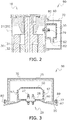
FIG. 2 is a cross-sectional view of a main part of thecompressor 10. -
FIG. 3 is a cross-sectional view of aterminal protection structure 90. -
FIG. 4 is a schematic view of theterminal protection structure 90. -
FIG. 5 is a schematic view of aterminal protection structure 90A of acompressor 10 according to a first modification of the first embodiment of the present invention. -
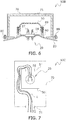
FIG. 6 is a cross-sectional view of aterminal protection structure 90B of acompressor 10 according to a second modification of the first embodiment of the present invention. -
FIG. 7 is a schematic view of aterminal protection structure 90C of acompressor 10 according to a third modification of the first embodiment of the present invention. -
FIG. 8 is a schematic view of aterminal protection structure 90D of acompressor 10 according to a fourth modification of the first embodiment of the present invention. -
FIG. 9 is a schematic view of theterminal protection structure 90D of thecompressor 10 according to the fourth modification of the first embodiment of the present invention. -
FIG. 10 is a cross-sectional view of a terminal protection structure 90' of a compressor according to a second embodiment of the present invention. -
FIG. 11 is a perspective view of the terminal protection structure 90' of the compressor according to the second embodiment of the present invention. -
FIG. 1 illustrates acompressor 10 according to a first embodiment of the present invention. Thecompressor 10 is mounted in a refrigeration machine such as an air conditioner in order to compress refrigerant which is a fluid. Thecompressor 10 is a scroll compressor. Thecompressor 10 includes acasing 20, amotor 30, acrankshaft 35, and acompression mechanism 40. Thecasing 20 includes abody portion 21, anupper portion 22, and alower portion 23. Thecompression mechanism 40 includes a fixedscroll 41 and amovable scroll 42, and definescompression chambers 43. - Power supplied from the outside excites a coil installed in a
stator 31 of themotor 30, whereby arotor 32 rotates. The rotation of therotor 32 is transmitted to amain shaft portion 36 of thecrankshaft 35. Themovable scroll 42 revolves with respect to the fixedscroll 41 by the power transmitted from aneccentric portion 37 of thecrankshaft 35. Low-pressure gas refrigerant sucked through asuction pipe 15 enters thecompression chamber 43 on the outer peripheral side of thecompression mechanism 40. As themovable scroll 42 revolves, thecompression chamber 43 moves toward the center of thecompression mechanism 40 while reducing the volume of thecompression chamber 43. During this process, the low-pressure gas refrigerant is compressed to turn into high-pressure gas refrigerant. The high-pressure gas refrigerant is discharged to the outside of thecompression mechanism 40 through adischarge port 44, and moves to a space inside the casing. Then, the high-pressure gas refrigerant is discharged to the outside of thecasing 20 through adischarge pipe 16. -
FIG. 2 is a cross-sectional view of thecompressor 10 taken along a cross section different from that ofFIG. 1 . Thecompressor 10 further includes a terminal 29 and aterminal protection structure 90 for preventing an object or user from contacting the terminal 29.FIG. 3 is a schematic cross-sectional view of theterminal protection structure 90 on a horizontal plane. Theterminal protection structure 90 includes afirst cover 50, afirst cover support 60, asecond cover 70, and asecond cover support 80. Each element will be described in detail below. - The terminal 29 is for supplying power to the
motor 30. As illustrated inFIG. 3 , the terminal 29 includes terminal pins 27 and aterminal base 28 that supports the terminal pins 27. A lead wire (not illustrated) for power supply is connected to the terminal pins 27. The terminal 29 is installed while protruding from thecasing 20. - The
first cover support 60 is provided on thecasing 20 while surrounding the terminal 29. Thefirst cover support 60 is, for example, a metal member welded to thecasing 20. As illustrated inFIG. 2 , thefirst cover support 60 is provided with a firstcover support opening 62 through which the lead wire passes. - The
first cover 50 illustrated inFIG. 3 is a resin cover configured to cover the terminal 29. Thefirst cover 50 is configured to fit on the inner side of thefirst cover support 60. Thefirst cover 50 is attachable to and detachable from thefirst cover support 60. Thefirst cover 50 includesclaw portions 57. Thefirst cover 50 is attached to thefirst cover support 60 by theclaw portions 57 engaging withholes 67 provided at thefirst cover support 60. The volume of a space formed by thefirst cover 50 is a first volume C1. As illustrated inFIG. 2 , thefirst cover 50 is provided with afirst opening 52 through which the lead wire passes. With thefirst cover 50 attached to thefirst cover support 60, thefirst opening 52 overlaps the firstcover support opening 62, thereby allowing the lead wire to pass therethrough. - The
second cover support 80 illustrated inFIG. 3 is a metal member welded to thecasing 20. Thesecond cover support 80 is provided with ascrew hole 87 for afastener 89 such as a bolt or a screw. - The
second cover 70 is a metal cover configured to cover thefirst cover 50. Thesecond cover 70 is attachable to and detachable from thesecond cover support 80 independently of thefirst cover 50. Thesecond cover 70 has throughholes 77 through which thefasteners 89 pass. Thesecond cover 70 is fastened to thesecond cover support 80 by thefasteners 89. - For example, a flame-extinguishing
member 75 may be provided on the inner surface of thesecond cover 70. In an unlikely event where refrigeration oil or flammable refrigerant spouts from an opening such as a crack generated in thecasing 20 due to removal of the terminal 29 and the spouted material ignites, the flame-extinguishingmember 75 lowers the temperature of the spouted material and restrains the flame from spreading to the outside. Examples of the flame-extinguishingmember 75 include a metal mesh, a metal honeycomb, and a metal porous plate. - The volume of a space formed by the
second cover 70 is a second volume C2. A differential volume CD obtained by subtracting the first volume C1 from the second volume C2 is set to be larger than the first volume C1. -
FIG. 4 is a schematic view of theterminal protection structure 90. Thefirst opening 52 is formed in a firstopening side surface 51 of thefirst cover 50. Asecond opening 72 is formed in a secondopening side surface 71 of thesecond cover 70. With thesecond cover 70 attached to thesecond cover support 80, a lead wire L can pass through thesecond opening 72. The lead wire L extends from the terminal 29 through thefirst opening 52 and thesecond opening 72 to the outside of theterminal protection structure 90. - As illustrated in
FIG. 4 , the firstopening side surface 51 is a lower surface of the first cover. The secondopening side surface 71 is a left surface of the second cover. The firstopening side surface 51 and the secondopening side surface 71 do not face each other. The firstopening side surface 51 and the secondopening side surface 71 are not parallel to each other but, for example, perpendicular to each other. - The
first cover 50 is covered by thesecond cover 70. Therefore, even if thefirst cover 50 is damaged and broken due to the refrigerant leaking from a broken part of the terminal 29, scattered matters such as fragments of the terminal 29 and thefirst cover 50 are blocked by thesecond cover 70. This restrains occurrence of an accident such as injury of a user. - The
first cover 50 located close to the terminal 29 is made of resin. Therefore, the fragments of thefirst cover 50 do not cause undesirable conduction between the terminal pins 27. Thesecond cover 70 disposed on the outer side is made of metal, and therefore can withstand the collision of scattered matters. - The differential volume CD is larger than the first volume C1. This configuration is suitable for reducing the force of the refrigerant or scattered matters spouting from a broken part of the terminal 29.
- The leaked refrigerant collides with the metal flame-extinguishing
member 75. Therefore, the flame-extinguishingmember 75 restrains the ignition even if there is an ignition cause such as refrigerant, droplets of refrigeration oil, or an electric spark. - The flame-extinguishing
member 75 is formed of a metal structure. Therefore, the flame-extinguishingmember 75 absorbs heat upon contact with the refrigerant or droplets of the refrigeration oil, for example. This configuration further restrains the ignition. - The first
opening side surface 51 and the secondopening side surface 71 do not face each other. When ignition occurs at a broken part of the terminal, therefore, the flame is less likely to go out of thesecond cover 70. - The first
opening side surface 51 and the secondopening side surface 71 are not parallel to each other. Therefore, the flame ejected from a broken part of the terminal toward thefirst opening 52 is less likely to go out of thesecond cover 70 through thesecond opening 72. - The
first cover 50 and thesecond cover 70 are attached independently of each other. This structure restrains scattering of thesecond cover 70 caused by scattering of thefirst cover 50. - The
second cover 70 is fastened to thesecond cover support 80 by thefasteners 89 such as bolts. Therefore, the second cover is firmly fixed. - Modifications of the above embodiment will be described below. For example, a plurality of modifications may be combined.
-
FIG. 5 illustrates aterminal protection structure 90A according to a first modification. Theterminal protection structure 90A is different from that of the above embodiment in that aseal material 73 is installed around a lead wire L at asecond opening 72. Examples of theseal material 73 that can be used include a silicone foam sheet. - According to this configuration, the
seal material 73 fills a gap around the lead wire L. This restrains oxygen supply to the inside of thesecond cover 70. Flame inside thesecond cover 70 is less likely to spread to the outside through thesecond opening 72. -
FIG. 6 illustrates aterminal protection structure 90B according to the first modification. Theterminal protection structure 90B is different from that of the above embodiment in that afirst cover 50 is attached to afirst cover support 60 byfasteners 69, not by the engaging claw portions. Thefasteners 69 are bolts or screws, for example. - According to this configuration, the
first cover 50 is fastened to thefirst cover support 60 by thefasteners 69. Therefore, thefirst cover 50 is firmly fixed. -
FIG. 7 illustrates aterminal protection structure 90C according to a second modification. Theterminal protection structure 90C is different from that of the above embodiment in the positional relationship between afirst opening 52 and asecond opening 72. - A first
opening side surface 51 having thefirst opening 52 is an upper surface of afirst cover 50. A secondopening side surface 71 having thesecond opening 72 is a lower surface of asecond cover 70. - According to this configuration, the first
opening side surface 51 and the secondopening side surface 71 do not face each other. When ignition occurs at a broken part of the terminal, therefore, the flame is less likely to go out of thesecond cover 70. -
FIGS. 8 and 9 illustrate aterminal protection structure 90D according to a third modification. Theterminal protection structure 90D is different from that of the above embodiment in the positional relationship between afirst opening 52 and asecond opening 72. - As illustrated in
FIG. 8 , a firstopening side surface 51 having thefirst opening 52 is a lower surface of afirst cover 50. A secondopening side surface 71 having thesecond opening 72 is a lower surface of asecond cover 70. That is, the firstopening side surface 51 and the secondopening side surface 71 face each other. - The first
opening side surface 51 and the surface of thesecond cover 70 facing the first opening side surface 51 (the secondopening side surface 71 in this modification) are separated by a distance S. The distance S is, for example, 20 mm or more. - The relationship between the
first opening 52 and thesecond opening 72 can be understood fromFIG. 9 . The area of thefirst opening 52 is larger than the area of thesecond opening 72. The center of thefirst opening 52 is separated from thecasing 20 by a first distance D1. The center of thesecond opening 72 is separated from thecasing 20 by a second distance D2. The first distance D1 is different from the second distance D2. The first distance D1 is larger than the second distance D2. - According to this configuration, the first
opening side surface 51 and the secondopening side surface 71 face each other. This makes it easy to route the lead wire L such that the lead wire L passes through both thefirst opening 52 and thesecond opening 72. - Since the area of the
second opening 72 is small, flame is less likely to go out of the second opening at the time of ignition. The misalignment between the center of thefirst opening 52 and the center of thesecond opening 72 also helps to restrain the flame leaking outside. - Since the first
opening side surface 51 of thefirst cover 50 and the surface of thesecond cover 70 facing the firstopening side surface 51 are separated by 20 mm or more, a space is generated between thefirst cover 50 and thesecond cover 70. Therefore, the force of the flame can be weakened in that space. - In the embodiment and modifications described above, the first
opening side surface 51 is the lower or upper surface of thefirst cover 50 and the secondopening side surface 71 is the left or lower surface of thesecond cover 70. Alternatively, the firstopening side surface 51 may be other than the lower or upper surface of thefirst cover 50 and the secondopening side surface 71 may be other than the left or lower surface of thesecond cover 70. - This configuration makes it possible to implement a design that meets various design constraints.
- In the embodiment described above, the
first cover 50 is configured to fit on the inner side of thefirst cover support 60. Alternatively, thefirst cover 50 may be configured to fit on the outer side of thefirst cover support 60. - This configuration may facilitate the work of attaching the
first cover 50 to thefirst cover support 60. - In the above embodiment, the
compressor 10, in which theterminal protection structure 90 of the present application is mounted, is a scroll compressor. Alternatively, theterminal protection structure 90 may be mounted in another type of compressor, such as a rotary compressor. -
FIGS. 10 and 11 illustrate a terminal protection structure 90' of a compressor according to a second embodiment of the present invention. In the terminal protection structure 90', a first cover 50' is fixed to a second cover 70'. Specifically, the first cover 50' is an insulating sheet. The first cover 50' is attached to the second cover 70'. - The first cover 50' and the second cover 70' are fastened to a cover support 60' by common fasteners 69'. The cover support 60' has a structure similar to that of the
first cover support 60 according to the first modification of the first embodiment. That is, the cover support 60' can independently fasten, with the fasteners 69', thefirst cover 50 according to the first modification of the first embodiment in place of the first cover 50' and the second cover 70' according to the present embodiment. - The first cover 50' is fixed to the second cover 70'. In addition, both the first cover 50' and the second cover 70' are fastened to the cover support 60' by the common fasteners 69'. This facilitates the attachment of the first cover 50' and the second cover 70' to a
casing 20. - A first space Q1 is formed on the inner side of the cover support 60', while a second space Q2 is formed on the outer side of the cover support 60'. When flame is ejected from the first space Q1, the ejected flame is attenuated in the second space Q2. This restrains the flame going out of the second cover 70'.
- In the embodiment described above, the
first cover 50 is an insulating sheet attached to thesecond cover 70. Alternatively, thefirst cover 50 may be an insulating paint applied to thesecond cover 70. - For example, each modification of the first embodiment may be applied to the second embodiment.
-
- 10
- Compressor
- 20
- Casing
- 29
- Terminal
- 50, 50'
- First cover
- 60
- First cover support
- 60'
- Cover support
- 69, 69'
- Fastener
- 70, 70'
- Second cover
- 80
- Second cover support
- 89
- Fastener
- 90, 90A, 90B, 90C, 90D, 90'
- Terminal protection structure
- [Patent Document 1]
JP 2007-146728 A
Claims (21)
- A compressor (10) comprising:a casing (20);a terminal (29) protruding from the casing;a first cover (50) covering the terminal; anda second cover (70) covering the first cover.
- The compressor according to claim 1,
wherein the first cover includes resin, and the second cover includes metal. - The compressor according to claim 1 or 2,
wherein a differential volume (CD) obtained by subtracting a first volume (C1), which is a volume of the first cover, from a second volume (C2), which is a volume of the second cover, is larger than the first volume. - The compressor according to any one of claims 1 to 3,
wherein a flame-extinguishing member (75) is provided on an inner surface of the second cover. - The compressor according to any one of claims 1 to 4,wherein the first cover includes a first opening side surface (51) in which a first opening (52) for passing a lead wire is formed, andthe second cover includes a second opening side surface (71) in which a second opening (72) for passing the lead wire is formed.
- The compressor according to claim 5,
wherein the second opening is provided with a seal material (73) that restrains flow of air passing through the second opening. - The compressor according to claim 5 or 6,
wherein the first opening side surface and the second opening side surface do not face each other. - The compressor according to claim 7,
wherein the first opening side surface and the second opening side surface are not parallel to each other. - The compressor according to claim 5 or 6,
wherein the first opening side surface and the second opening side surface face each other. - The compressor according to any one of claims 5 to 9,
wherein the first opening has an area larger than an area of the second opening. - The compressor according to any one of claims 5 to 10,wherein the first opening has a center separated from the casing by a first distance (D1),the second opening has a center separated from the casing by a second distance (D2), andthe first distance is different from the second distance.
- The compressor according to claim 11,
wherein the first distance is larger than the second distance. - The compressor according to any one of claims 5 to 12,
wherein the first opening side surface and a surface of the second cover facing the first opening side surface are separated by 20 mm or more. - The compressor according to any one of claims 1 to 13,wherein the casing is provided with a first cover support (60) and a second cover support (80),the first cover is attachable to and detachable from the first cover support, andthe second cover is attachable to and detachable from the second cover support independently of the first cover.
- The compressor according to claim 14,
wherein the second cover is fastened to the second cover support by a bolt. - The compressor according to claim 14 or 15,
wherein the first cover is fastened to the first cover support by a bolt. - The compressor according to any one of claims 1 to 13,
wherein the first cover is fixed to the second cover. - The compressor according to claim 17,
wherein the first cover is a sheet attached to the second cover. - The compressor according to claim 17,
wherein the first cover is a paint applied to the second cover. - The compressor according to any one of claims 17 to 19,wherein the casing is provided with a cover support (69'), andboth the first cover and the second cover are fastened to the cover support by a common fastener.
- The compressor according to claim 20,
wherein the second cover is configured to be independently fastened to the cover support by a fastener.
Applications Claiming Priority (2)
| Application Number | Priority Date | Filing Date | Title |
|---|---|---|---|
| JP2017082517 | 2017-04-19 | ||
| PCT/JP2018/016044 WO2018194106A1 (en) | 2017-04-19 | 2018-04-18 | Compressor having terminal protection structure |
Publications (3)
| Publication Number | Publication Date |
|---|---|
| EP3587816A1 true EP3587816A1 (en) | 2020-01-01 |
| EP3587816A4 EP3587816A4 (en) | 2020-01-22 |
| EP3587816B1 EP3587816B1 (en) | 2021-07-07 |
Family
ID=63855915
Family Applications (1)
| Application Number | Title | Priority Date | Filing Date |
|---|---|---|---|
| EP18787893.9A Active EP3587816B1 (en) | 2017-04-19 | 2018-04-18 | Compressor having terminal protection structure |
Country Status (6)
| Country | Link |
|---|---|
| US (1) | US11085443B2 (en) |
| EP (1) | EP3587816B1 (en) |
| JP (2) | JP6555383B2 (en) |
| CN (1) | CN110431307B (en) |
| ES (1) | ES2884793T3 (en) |
| WO (1) | WO2018194106A1 (en) |
Families Citing this family (5)
| Publication number | Priority date | Publication date | Assignee | Title |
|---|---|---|---|---|
| CN209948088U (en) * | 2019-07-15 | 2020-01-14 | 上海海立电器有限公司 | Wiring device and compressor |
| JP7269829B2 (en) * | 2019-08-23 | 2023-05-09 | 東芝キヤリア株式会社 | Compressor and refrigeration cycle equipment |
| JP7484646B2 (en) * | 2019-12-13 | 2024-05-16 | 日本精工株式会社 | Motor unit and electric power steering device |
| JP2022124314A (en) * | 2021-02-15 | 2022-08-25 | パナソニックIpマネジメント株式会社 | air conditioner |
| JP7689305B2 (en) * | 2021-06-29 | 2025-06-06 | パナソニックIpマネジメント株式会社 | Compressor |
Family Cites Families (14)
| Publication number | Priority date | Publication date | Assignee | Title |
|---|---|---|---|---|
| JPS51126408U (en) | 1975-04-09 | 1976-10-13 | ||
| JPS6110060U (en) | 1984-06-20 | 1986-01-21 | 松下電器産業株式会社 | Compressor terminal protection device |
| JPH01144477U (en) | 1988-03-29 | 1989-10-04 | ||
| JP2599027B2 (en) | 1990-10-30 | 1997-04-09 | 三洋電機株式会社 | Compressor terminal waterproof device |
| JP3128892B2 (en) | 1991-10-11 | 2001-01-29 | 松下電器産業株式会社 | Power terminal protection device for compressor |
| JPH09158838A (en) | 1995-12-05 | 1997-06-17 | Matsushita Electric Ind Co Ltd | Refrigerating air conditioner and hermetic compressor |
| JP2001020861A (en) | 1999-07-08 | 2001-01-23 | Daikin Ind Ltd | Compressor |
| JP4171321B2 (en) | 2003-02-14 | 2008-10-22 | 三洋電機株式会社 | Multistage compression compressor |
| JP3995013B2 (en) | 2005-11-25 | 2007-10-24 | ダイキン工業株式会社 | Terminal protection structure |
| JP2007170252A (en) * | 2005-12-21 | 2007-07-05 | Daikin Ind Ltd | Terminal structure and compressor |
| JP5029491B2 (en) | 2008-05-22 | 2012-09-19 | パナソニック株式会社 | Electrical component cover and method of manufacturing the same |
| JP2010024940A (en) | 2008-07-18 | 2010-02-04 | Panasonic Corp | Electrical apparatus cover |
| JP5990454B2 (en) * | 2012-12-25 | 2016-09-14 | 矢崎総業株式会社 | Shield connector structure |
| CN103615383B (en) * | 2013-12-04 | 2016-04-06 | Tcl空调器(中山)有限公司 | Compressor, Wiring protection device and overload protective device that tool wiring is protected |
-
2018
- 2018-04-18 WO PCT/JP2018/016044 patent/WO2018194106A1/en not_active Ceased
- 2018-04-18 JP JP2018080019A patent/JP6555383B2/en active Active
- 2018-04-18 CN CN201880013618.8A patent/CN110431307B/en active Active
- 2018-04-18 US US16/491,016 patent/US11085443B2/en active Active
- 2018-04-18 ES ES18787893T patent/ES2884793T3/en active Active
- 2018-04-18 EP EP18787893.9A patent/EP3587816B1/en active Active
- 2018-09-18 JP JP2018173874A patent/JP6766852B2/en active Active
Also Published As
| Publication number | Publication date |
|---|---|
| WO2018194106A1 (en) | 2018-10-25 |
| EP3587816A4 (en) | 2020-01-22 |
| US20200032792A1 (en) | 2020-01-30 |
| CN110431307A (en) | 2019-11-08 |
| JP2019002408A (en) | 2019-01-10 |
| JP6766852B2 (en) | 2020-10-14 |
| JP2018179006A (en) | 2018-11-15 |
| JP6555383B2 (en) | 2019-08-07 |
| ES2884793T3 (en) | 2021-12-13 |
| CN110431307B (en) | 2021-07-13 |
| US11085443B2 (en) | 2021-08-10 |
| EP3587816B1 (en) | 2021-07-07 |
Similar Documents
| Publication | Publication Date | Title |
|---|---|---|
| EP3587816B1 (en) | Compressor having terminal protection structure | |
| KR101494084B1 (en) | Motor-driven compressor | |
| EP2527654B1 (en) | Compressor | |
| US20110223010A1 (en) | Device for sealing a bearing housing of an exhaust gas turbocharger | |
| CN107534354B (en) | Motor housing for electric compressor and vehicle-mounted electric compressor using same | |
| US20160190894A1 (en) | Electric compressor | |
| US20150352477A1 (en) | Mist separator | |
| JP2009092000A (en) | Compressor for on-vehicle air-conditioner | |
| JP2009103100A (en) | Electric compressor for vehicles | |
| EP2103808B1 (en) | Scroll compressor | |
| EP2196672A1 (en) | Electrically driven compressor used for vehicle | |
| JP2010158991A (en) | Arrangement structure of electric compressor | |
| CN108691787A (en) | Vacuum pump | |
| EP3795390A1 (en) | Air conditioning device for vehicle | |
| KR20180076305A (en) | Electric compressor | |
| JP4839581B2 (en) | Fuel cell case structure | |
| JP2010121449A (en) | Inverter integrated type electric compressor | |
| EP1775179A2 (en) | Gas generator for airbag | |
| JP2017078334A (en) | Motor compressor | |
| CN113048037B (en) | Compressors and refrigeration equipment | |
| CN211202297U (en) | Compressor and vehicle | |
| KR100892524B1 (en) | Inlet for cooling internal batteries and high voltage components | |
| CN219304580U (en) | Driving motor respirator protective structure and automobile driving motor | |
| CN113048038B (en) | Compressors and refrigeration equipment | |
| KR20180018647A (en) | Scroll compressor |
Legal Events
| Date | Code | Title | Description |
|---|---|---|---|
| STAA | Information on the status of an ep patent application or granted ep patent |
Free format text: STATUS: THE INTERNATIONAL PUBLICATION HAS BEEN MADE |
|
| PUAI | Public reference made under article 153(3) epc to a published international application that has entered the european phase |
Free format text: ORIGINAL CODE: 0009012 |
|
| STAA | Information on the status of an ep patent application or granted ep patent |
Free format text: STATUS: REQUEST FOR EXAMINATION WAS MADE |
|
| 17P | Request for examination filed |
Effective date: 20190904 |
|
| AK | Designated contracting states |
Kind code of ref document: A1 Designated state(s): AL AT BE BG CH CY CZ DE DK EE ES FI FR GB GR HR HU IE IS IT LI LT LU LV MC MK MT NL NO PL PT RO RS SE SI SK SM TR |
|
| AX | Request for extension of the european patent |
Extension state: BA ME |
|
| A4 | Supplementary search report drawn up and despatched |
Effective date: 20200103 |
|
| RIC1 | Information provided on ipc code assigned before grant |
Ipc: F04B 39/00 20060101AFI20191218BHEP Ipc: H02K 5/22 20060101ALI20191218BHEP Ipc: F04B 35/04 20060101ALI20191218BHEP Ipc: F04B 39/12 20060101ALI20191218BHEP |
|
| DAV | Request for validation of the european patent (deleted) | ||
| DAX | Request for extension of the european patent (deleted) | ||
| STAA | Information on the status of an ep patent application or granted ep patent |
Free format text: STATUS: EXAMINATION IS IN PROGRESS |
|
| 17Q | First examination report despatched |
Effective date: 20200924 |
|
| GRAJ | Information related to disapproval of communication of intention to grant by the applicant or resumption of examination proceedings by the epo deleted |
Free format text: ORIGINAL CODE: EPIDOSDIGR1 |
|
| STAA | Information on the status of an ep patent application or granted ep patent |
Free format text: STATUS: GRANT OF PATENT IS INTENDED |
|
| GRAP | Despatch of communication of intention to grant a patent |
Free format text: ORIGINAL CODE: EPIDOSNIGR1 |
|
| INTG | Intention to grant announced |
Effective date: 20210224 |
|
| GRAS | Grant fee paid |
Free format text: ORIGINAL CODE: EPIDOSNIGR3 |
|
| GRAA | (expected) grant |
Free format text: ORIGINAL CODE: 0009210 |
|
| STAA | Information on the status of an ep patent application or granted ep patent |
Free format text: STATUS: THE PATENT HAS BEEN GRANTED |
|
| AK | Designated contracting states |
Kind code of ref document: B1 Designated state(s): AL AT BE BG CH CY CZ DE DK EE ES FI FR GB GR HR HU IE IS IT LI LT LU LV MC MK MT NL NO PL PT RO RS SE SI SK SM TR |
|
| REG | Reference to a national code |
Ref country code: GB Ref legal event code: FG4D |
|
| REG | Reference to a national code |
Ref country code: AT Ref legal event code: REF Ref document number: 1408830 Country of ref document: AT Kind code of ref document: T Effective date: 20210715 |
|
| REG | Reference to a national code |
Ref country code: DE Ref legal event code: R096 Ref document number: 602018019848 Country of ref document: DE |
|
| REG | Reference to a national code |
Ref country code: IE Ref legal event code: FG4D |
|
| REG | Reference to a national code |
Ref country code: LT Ref legal event code: MG9D |
|
| REG | Reference to a national code |
Ref country code: NL Ref legal event code: MP Effective date: 20210707 |
|
| REG | Reference to a national code |
Ref country code: ES Ref legal event code: FG2A Ref document number: 2884793 Country of ref document: ES Kind code of ref document: T3 Effective date: 20211213 |
|
| REG | Reference to a national code |
Ref country code: AT Ref legal event code: MK05 Ref document number: 1408830 Country of ref document: AT Kind code of ref document: T Effective date: 20210707 |
|
| PG25 | Lapsed in a contracting state [announced via postgrant information from national office to epo] |
Ref country code: FI Free format text: LAPSE BECAUSE OF FAILURE TO SUBMIT A TRANSLATION OF THE DESCRIPTION OR TO PAY THE FEE WITHIN THE PRESCRIBED TIME-LIMIT Effective date: 20210707 Ref country code: HR Free format text: LAPSE BECAUSE OF FAILURE TO SUBMIT A TRANSLATION OF THE DESCRIPTION OR TO PAY THE FEE WITHIN THE PRESCRIBED TIME-LIMIT Effective date: 20210707 Ref country code: SE Free format text: LAPSE BECAUSE OF FAILURE TO SUBMIT A TRANSLATION OF THE DESCRIPTION OR TO PAY THE FEE WITHIN THE PRESCRIBED TIME-LIMIT Effective date: 20210707 Ref country code: RS Free format text: LAPSE BECAUSE OF FAILURE TO SUBMIT A TRANSLATION OF THE DESCRIPTION OR TO PAY THE FEE WITHIN THE PRESCRIBED TIME-LIMIT Effective date: 20210707 Ref country code: LT Free format text: LAPSE BECAUSE OF FAILURE TO SUBMIT A TRANSLATION OF THE DESCRIPTION OR TO PAY THE FEE WITHIN THE PRESCRIBED TIME-LIMIT Effective date: 20210707 Ref country code: BG Free format text: LAPSE BECAUSE OF FAILURE TO SUBMIT A TRANSLATION OF THE DESCRIPTION OR TO PAY THE FEE WITHIN THE PRESCRIBED TIME-LIMIT Effective date: 20211007 Ref country code: AT Free format text: LAPSE BECAUSE OF FAILURE TO SUBMIT A TRANSLATION OF THE DESCRIPTION OR TO PAY THE FEE WITHIN THE PRESCRIBED TIME-LIMIT Effective date: 20210707 Ref country code: PT Free format text: LAPSE BECAUSE OF FAILURE TO SUBMIT A TRANSLATION OF THE DESCRIPTION OR TO PAY THE FEE WITHIN THE PRESCRIBED TIME-LIMIT Effective date: 20211108 Ref country code: NL Free format text: LAPSE BECAUSE OF FAILURE TO SUBMIT A TRANSLATION OF THE DESCRIPTION OR TO PAY THE FEE WITHIN THE PRESCRIBED TIME-LIMIT Effective date: 20210707 Ref country code: NO Free format text: LAPSE BECAUSE OF FAILURE TO SUBMIT A TRANSLATION OF THE DESCRIPTION OR TO PAY THE FEE WITHIN THE PRESCRIBED TIME-LIMIT Effective date: 20211007 |
|
| PG25 | Lapsed in a contracting state [announced via postgrant information from national office to epo] |
Ref country code: PL Free format text: LAPSE BECAUSE OF FAILURE TO SUBMIT A TRANSLATION OF THE DESCRIPTION OR TO PAY THE FEE WITHIN THE PRESCRIBED TIME-LIMIT Effective date: 20210707 Ref country code: LV Free format text: LAPSE BECAUSE OF FAILURE TO SUBMIT A TRANSLATION OF THE DESCRIPTION OR TO PAY THE FEE WITHIN THE PRESCRIBED TIME-LIMIT Effective date: 20210707 Ref country code: GR Free format text: LAPSE BECAUSE OF FAILURE TO SUBMIT A TRANSLATION OF THE DESCRIPTION OR TO PAY THE FEE WITHIN THE PRESCRIBED TIME-LIMIT Effective date: 20211008 |
|
| REG | Reference to a national code |
Ref country code: DE Ref legal event code: R097 Ref document number: 602018019848 Country of ref document: DE |
|
| PG25 | Lapsed in a contracting state [announced via postgrant information from national office to epo] |
Ref country code: DK Free format text: LAPSE BECAUSE OF FAILURE TO SUBMIT A TRANSLATION OF THE DESCRIPTION OR TO PAY THE FEE WITHIN THE PRESCRIBED TIME-LIMIT Effective date: 20210707 |
|
| PLBE | No opposition filed within time limit |
Free format text: ORIGINAL CODE: 0009261 |
|
| STAA | Information on the status of an ep patent application or granted ep patent |
Free format text: STATUS: NO OPPOSITION FILED WITHIN TIME LIMIT |
|
| PG25 | Lapsed in a contracting state [announced via postgrant information from national office to epo] |
Ref country code: SM Free format text: LAPSE BECAUSE OF FAILURE TO SUBMIT A TRANSLATION OF THE DESCRIPTION OR TO PAY THE FEE WITHIN THE PRESCRIBED TIME-LIMIT Effective date: 20210707 Ref country code: SK Free format text: LAPSE BECAUSE OF FAILURE TO SUBMIT A TRANSLATION OF THE DESCRIPTION OR TO PAY THE FEE WITHIN THE PRESCRIBED TIME-LIMIT Effective date: 20210707 Ref country code: RO Free format text: LAPSE BECAUSE OF FAILURE TO SUBMIT A TRANSLATION OF THE DESCRIPTION OR TO PAY THE FEE WITHIN THE PRESCRIBED TIME-LIMIT Effective date: 20210707 Ref country code: EE Free format text: LAPSE BECAUSE OF FAILURE TO SUBMIT A TRANSLATION OF THE DESCRIPTION OR TO PAY THE FEE WITHIN THE PRESCRIBED TIME-LIMIT Effective date: 20210707 Ref country code: CZ Free format text: LAPSE BECAUSE OF FAILURE TO SUBMIT A TRANSLATION OF THE DESCRIPTION OR TO PAY THE FEE WITHIN THE PRESCRIBED TIME-LIMIT Effective date: 20210707 Ref country code: AL Free format text: LAPSE BECAUSE OF FAILURE TO SUBMIT A TRANSLATION OF THE DESCRIPTION OR TO PAY THE FEE WITHIN THE PRESCRIBED TIME-LIMIT Effective date: 20210707 |
|
| 26N | No opposition filed |
Effective date: 20220408 |
|
| REG | Reference to a national code |
Ref country code: CH Ref legal event code: PL |
|
| REG | Reference to a national code |
Ref country code: BE Ref legal event code: MM Effective date: 20220430 |
|
| PG25 | Lapsed in a contracting state [announced via postgrant information from national office to epo] |
Ref country code: MC Free format text: LAPSE BECAUSE OF FAILURE TO SUBMIT A TRANSLATION OF THE DESCRIPTION OR TO PAY THE FEE WITHIN THE PRESCRIBED TIME-LIMIT Effective date: 20210707 Ref country code: LU Free format text: LAPSE BECAUSE OF NON-PAYMENT OF DUE FEES Effective date: 20220418 Ref country code: LI Free format text: LAPSE BECAUSE OF NON-PAYMENT OF DUE FEES Effective date: 20220430 Ref country code: CH Free format text: LAPSE BECAUSE OF NON-PAYMENT OF DUE FEES Effective date: 20220430 |
|
| PG25 | Lapsed in a contracting state [announced via postgrant information from national office to epo] |
Ref country code: BE Free format text: LAPSE BECAUSE OF NON-PAYMENT OF DUE FEES Effective date: 20220430 |
|
| PG25 | Lapsed in a contracting state [announced via postgrant information from national office to epo] |
Ref country code: IE Free format text: LAPSE BECAUSE OF NON-PAYMENT OF DUE FEES Effective date: 20220418 |
|
| P01 | Opt-out of the competence of the unified patent court (upc) registered |
Effective date: 20230525 |
|
| PG25 | Lapsed in a contracting state [announced via postgrant information from national office to epo] |
Ref country code: MK Free format text: LAPSE BECAUSE OF FAILURE TO SUBMIT A TRANSLATION OF THE DESCRIPTION OR TO PAY THE FEE WITHIN THE PRESCRIBED TIME-LIMIT Effective date: 20210707 Ref country code: CY Free format text: LAPSE BECAUSE OF FAILURE TO SUBMIT A TRANSLATION OF THE DESCRIPTION OR TO PAY THE FEE WITHIN THE PRESCRIBED TIME-LIMIT Effective date: 20210707 |
|
| PG25 | Lapsed in a contracting state [announced via postgrant information from national office to epo] |
Ref country code: HU Free format text: LAPSE BECAUSE OF FAILURE TO SUBMIT A TRANSLATION OF THE DESCRIPTION OR TO PAY THE FEE WITHIN THE PRESCRIBED TIME-LIMIT; INVALID AB INITIO Effective date: 20180418 |
|
| PG25 | Lapsed in a contracting state [announced via postgrant information from national office to epo] |
Ref country code: MT Free format text: LAPSE BECAUSE OF FAILURE TO SUBMIT A TRANSLATION OF THE DESCRIPTION OR TO PAY THE FEE WITHIN THE PRESCRIBED TIME-LIMIT Effective date: 20210707 |
|
| PGFP | Annual fee paid to national office [announced via postgrant information from national office to epo] |
Ref country code: DE Payment date: 20250305 Year of fee payment: 8 |
|
| PGFP | Annual fee paid to national office [announced via postgrant information from national office to epo] |
Ref country code: ES Payment date: 20250506 Year of fee payment: 8 |
|
| PG25 | Lapsed in a contracting state [announced via postgrant information from national office to epo] |
Ref country code: TR Free format text: LAPSE BECAUSE OF FAILURE TO SUBMIT A TRANSLATION OF THE DESCRIPTION OR TO PAY THE FEE WITHIN THE PRESCRIBED TIME-LIMIT Effective date: 20210707 |
|
| PGFP | Annual fee paid to national office [announced via postgrant information from national office to epo] |
Ref country code: GB Payment date: 20260313 Year of fee payment: 9 |
|
| PGFP | Annual fee paid to national office [announced via postgrant information from national office to epo] |
Ref country code: IT Payment date: 20260320 Year of fee payment: 9 |
|
| PGFP | Annual fee paid to national office [announced via postgrant information from national office to epo] |
Ref country code: FR Payment date: 20260309 Year of fee payment: 9 |