EP3587802B1 - Method and device for noise control of a plurality of wind turbine generator systems - Google Patents
Method and device for noise control of a plurality of wind turbine generator systems Download PDFInfo
- Publication number
- EP3587802B1 EP3587802B1 EP18893345.1A EP18893345A EP3587802B1 EP 3587802 B1 EP3587802 B1 EP 3587802B1 EP 18893345 A EP18893345 A EP 18893345A EP 3587802 B1 EP3587802 B1 EP 3587802B1
- Authority
- EP
- European Patent Office
- Prior art keywords
- wind turbine
- noise
- wind
- power
- influencing
- Prior art date
- Legal status (The legal status is an assumption and is not a legal conclusion. Google has not performed a legal analysis and makes no representation as to the accuracy of the status listed.)
- Active
Links
- 238000000034 method Methods 0.000 title claims description 32
- 238000004590 computer program Methods 0.000 claims description 8
- 230000003247 decreasing effect Effects 0.000 claims description 4
- 238000010248 power generation Methods 0.000 description 8
- 238000010586 diagram Methods 0.000 description 7
- 230000003287 optical effect Effects 0.000 description 3
- 238000012545 processing Methods 0.000 description 3
- 238000007796 conventional method Methods 0.000 description 2
- 238000001816 cooling Methods 0.000 description 2
- 230000006870 function Effects 0.000 description 2
- 238000004891 communication Methods 0.000 description 1
- 238000010276 construction Methods 0.000 description 1
- 238000011217 control strategy Methods 0.000 description 1
- 238000013461 design Methods 0.000 description 1
- 238000011161 development Methods 0.000 description 1
- 230000007613 environmental effect Effects 0.000 description 1
- 230000002093 peripheral effect Effects 0.000 description 1
- 230000004044 response Effects 0.000 description 1
- 230000003584 silencer Effects 0.000 description 1
Images


Classifications
-
- F—MECHANICAL ENGINEERING; LIGHTING; HEATING; WEAPONS; BLASTING
- F03—MACHINES OR ENGINES FOR LIQUIDS; WIND, SPRING, OR WEIGHT MOTORS; PRODUCING MECHANICAL POWER OR A REACTIVE PROPULSIVE THRUST, NOT OTHERWISE PROVIDED FOR
- F03D—WIND MOTORS
- F03D7/00—Controlling wind motors
- F03D7/02—Controlling wind motors the wind motors having rotation axis substantially parallel to the air flow entering the rotor
- F03D7/0296—Controlling wind motors the wind motors having rotation axis substantially parallel to the air flow entering the rotor to prevent, counteract or reduce noise emissions
-
- F—MECHANICAL ENGINEERING; LIGHTING; HEATING; WEAPONS; BLASTING
- F03—MACHINES OR ENGINES FOR LIQUIDS; WIND, SPRING, OR WEIGHT MOTORS; PRODUCING MECHANICAL POWER OR A REACTIVE PROPULSIVE THRUST, NOT OTHERWISE PROVIDED FOR
- F03D—WIND MOTORS
- F03D7/00—Controlling wind motors
-
- F—MECHANICAL ENGINEERING; LIGHTING; HEATING; WEAPONS; BLASTING
- F03—MACHINES OR ENGINES FOR LIQUIDS; WIND, SPRING, OR WEIGHT MOTORS; PRODUCING MECHANICAL POWER OR A REACTIVE PROPULSIVE THRUST, NOT OTHERWISE PROVIDED FOR
- F03D—WIND MOTORS
- F03D7/00—Controlling wind motors
- F03D7/02—Controlling wind motors the wind motors having rotation axis substantially parallel to the air flow entering the rotor
- F03D7/022—Adjusting aerodynamic properties of the blades
- F03D7/0224—Adjusting blade pitch
-
- F—MECHANICAL ENGINEERING; LIGHTING; HEATING; WEAPONS; BLASTING
- F03—MACHINES OR ENGINES FOR LIQUIDS; WIND, SPRING, OR WEIGHT MOTORS; PRODUCING MECHANICAL POWER OR A REACTIVE PROPULSIVE THRUST, NOT OTHERWISE PROVIDED FOR
- F03D—WIND MOTORS
- F03D7/00—Controlling wind motors
- F03D7/02—Controlling wind motors the wind motors having rotation axis substantially parallel to the air flow entering the rotor
- F03D7/0276—Controlling wind motors the wind motors having rotation axis substantially parallel to the air flow entering the rotor controlling rotor speed, e.g. variable speed
-
- F—MECHANICAL ENGINEERING; LIGHTING; HEATING; WEAPONS; BLASTING
- F03—MACHINES OR ENGINES FOR LIQUIDS; WIND, SPRING, OR WEIGHT MOTORS; PRODUCING MECHANICAL POWER OR A REACTIVE PROPULSIVE THRUST, NOT OTHERWISE PROVIDED FOR
- F03D—WIND MOTORS
- F03D7/00—Controlling wind motors
- F03D7/02—Controlling wind motors the wind motors having rotation axis substantially parallel to the air flow entering the rotor
- F03D7/028—Controlling wind motors the wind motors having rotation axis substantially parallel to the air flow entering the rotor controlling wind motor output power
-
- F—MECHANICAL ENGINEERING; LIGHTING; HEATING; WEAPONS; BLASTING
- F03—MACHINES OR ENGINES FOR LIQUIDS; WIND, SPRING, OR WEIGHT MOTORS; PRODUCING MECHANICAL POWER OR A REACTIVE PROPULSIVE THRUST, NOT OTHERWISE PROVIDED FOR
- F03D—WIND MOTORS
- F03D7/00—Controlling wind motors
- F03D7/02—Controlling wind motors the wind motors having rotation axis substantially parallel to the air flow entering the rotor
- F03D7/04—Automatic control; Regulation
- F03D7/042—Automatic control; Regulation by means of an electrical or electronic controller
- F03D7/048—Automatic control; Regulation by means of an electrical or electronic controller controlling wind farms
-
- F—MECHANICAL ENGINEERING; LIGHTING; HEATING; WEAPONS; BLASTING
- F05—INDEXING SCHEMES RELATING TO ENGINES OR PUMPS IN VARIOUS SUBCLASSES OF CLASSES F01-F04
- F05B—INDEXING SCHEME RELATING TO WIND, SPRING, WEIGHT, INERTIA OR LIKE MOTORS, TO MACHINES OR ENGINES FOR LIQUIDS COVERED BY SUBCLASSES F03B, F03D AND F03G
- F05B2260/00—Function
- F05B2260/82—Forecasts
- F05B2260/821—Parameter estimation or prediction
- F05B2260/8211—Parameter estimation or prediction of the weather
-
- F—MECHANICAL ENGINEERING; LIGHTING; HEATING; WEAPONS; BLASTING
- F05—INDEXING SCHEMES RELATING TO ENGINES OR PUMPS IN VARIOUS SUBCLASSES OF CLASSES F01-F04
- F05B—INDEXING SCHEME RELATING TO WIND, SPRING, WEIGHT, INERTIA OR LIKE MOTORS, TO MACHINES OR ENGINES FOR LIQUIDS COVERED BY SUBCLASSES F03B, F03D AND F03G
- F05B2260/00—Function
- F05B2260/96—Preventing, counteracting or reducing vibration or noise
-
- F—MECHANICAL ENGINEERING; LIGHTING; HEATING; WEAPONS; BLASTING
- F05—INDEXING SCHEMES RELATING TO ENGINES OR PUMPS IN VARIOUS SUBCLASSES OF CLASSES F01-F04
- F05B—INDEXING SCHEME RELATING TO WIND, SPRING, WEIGHT, INERTIA OR LIKE MOTORS, TO MACHINES OR ENGINES FOR LIQUIDS COVERED BY SUBCLASSES F03B, F03D AND F03G
- F05B2270/00—Control
- F05B2270/10—Purpose of the control system
- F05B2270/101—Purpose of the control system to control rotational speed (n)
-
- F—MECHANICAL ENGINEERING; LIGHTING; HEATING; WEAPONS; BLASTING
- F05—INDEXING SCHEMES RELATING TO ENGINES OR PUMPS IN VARIOUS SUBCLASSES OF CLASSES F01-F04
- F05B—INDEXING SCHEME RELATING TO WIND, SPRING, WEIGHT, INERTIA OR LIKE MOTORS, TO MACHINES OR ENGINES FOR LIQUIDS COVERED BY SUBCLASSES F03B, F03D AND F03G
- F05B2270/00—Control
- F05B2270/10—Purpose of the control system
- F05B2270/103—Purpose of the control system to affect the output of the engine
- F05B2270/1033—Power (if explicitly mentioned)
-
- F—MECHANICAL ENGINEERING; LIGHTING; HEATING; WEAPONS; BLASTING
- F05—INDEXING SCHEMES RELATING TO ENGINES OR PUMPS IN VARIOUS SUBCLASSES OF CLASSES F01-F04
- F05B—INDEXING SCHEME RELATING TO WIND, SPRING, WEIGHT, INERTIA OR LIKE MOTORS, TO MACHINES OR ENGINES FOR LIQUIDS COVERED BY SUBCLASSES F03B, F03D AND F03G
- F05B2270/00—Control
- F05B2270/30—Control parameters, e.g. input parameters
- F05B2270/301—Pressure
-
- F—MECHANICAL ENGINEERING; LIGHTING; HEATING; WEAPONS; BLASTING
- F05—INDEXING SCHEMES RELATING TO ENGINES OR PUMPS IN VARIOUS SUBCLASSES OF CLASSES F01-F04
- F05B—INDEXING SCHEME RELATING TO WIND, SPRING, WEIGHT, INERTIA OR LIKE MOTORS, TO MACHINES OR ENGINES FOR LIQUIDS COVERED BY SUBCLASSES F03B, F03D AND F03G
- F05B2270/00—Control
- F05B2270/30—Control parameters, e.g. input parameters
- F05B2270/32—Wind speeds
-
- F—MECHANICAL ENGINEERING; LIGHTING; HEATING; WEAPONS; BLASTING
- F05—INDEXING SCHEMES RELATING TO ENGINES OR PUMPS IN VARIOUS SUBCLASSES OF CLASSES F01-F04
- F05B—INDEXING SCHEME RELATING TO WIND, SPRING, WEIGHT, INERTIA OR LIKE MOTORS, TO MACHINES OR ENGINES FOR LIQUIDS COVERED BY SUBCLASSES F03B, F03D AND F03G
- F05B2270/00—Control
- F05B2270/30—Control parameters, e.g. input parameters
- F05B2270/321—Wind directions
-
- F—MECHANICAL ENGINEERING; LIGHTING; HEATING; WEAPONS; BLASTING
- F05—INDEXING SCHEMES RELATING TO ENGINES OR PUMPS IN VARIOUS SUBCLASSES OF CLASSES F01-F04
- F05B—INDEXING SCHEME RELATING TO WIND, SPRING, WEIGHT, INERTIA OR LIKE MOTORS, TO MACHINES OR ENGINES FOR LIQUIDS COVERED BY SUBCLASSES F03B, F03D AND F03G
- F05B2270/00—Control
- F05B2270/30—Control parameters, e.g. input parameters
- F05B2270/327—Rotor or generator speeds
-
- F—MECHANICAL ENGINEERING; LIGHTING; HEATING; WEAPONS; BLASTING
- F05—INDEXING SCHEMES RELATING TO ENGINES OR PUMPS IN VARIOUS SUBCLASSES OF CLASSES F01-F04
- F05B—INDEXING SCHEME RELATING TO WIND, SPRING, WEIGHT, INERTIA OR LIKE MOTORS, TO MACHINES OR ENGINES FOR LIQUIDS COVERED BY SUBCLASSES F03B, F03D AND F03G
- F05B2270/00—Control
- F05B2270/30—Control parameters, e.g. input parameters
- F05B2270/328—Blade pitch angle
-
- F—MECHANICAL ENGINEERING; LIGHTING; HEATING; WEAPONS; BLASTING
- F05—INDEXING SCHEMES RELATING TO ENGINES OR PUMPS IN VARIOUS SUBCLASSES OF CLASSES F01-F04
- F05B—INDEXING SCHEME RELATING TO WIND, SPRING, WEIGHT, INERTIA OR LIKE MOTORS, TO MACHINES OR ENGINES FOR LIQUIDS COVERED BY SUBCLASSES F03B, F03D AND F03G
- F05B2270/00—Control
- F05B2270/30—Control parameters, e.g. input parameters
- F05B2270/333—Noise or sound levels
-
- F—MECHANICAL ENGINEERING; LIGHTING; HEATING; WEAPONS; BLASTING
- F05—INDEXING SCHEMES RELATING TO ENGINES OR PUMPS IN VARIOUS SUBCLASSES OF CLASSES F01-F04
- F05B—INDEXING SCHEME RELATING TO WIND, SPRING, WEIGHT, INERTIA OR LIKE MOTORS, TO MACHINES OR ENGINES FOR LIQUIDS COVERED BY SUBCLASSES F03B, F03D AND F03G
- F05B2270/00—Control
- F05B2270/30—Control parameters, e.g. input parameters
- F05B2270/335—Output power or torque
-
- Y—GENERAL TAGGING OF NEW TECHNOLOGICAL DEVELOPMENTS; GENERAL TAGGING OF CROSS-SECTIONAL TECHNOLOGIES SPANNING OVER SEVERAL SECTIONS OF THE IPC; TECHNICAL SUBJECTS COVERED BY FORMER USPC CROSS-REFERENCE ART COLLECTIONS [XRACs] AND DIGESTS
- Y02—TECHNOLOGIES OR APPLICATIONS FOR MITIGATION OR ADAPTATION AGAINST CLIMATE CHANGE
- Y02E—REDUCTION OF GREENHOUSE GAS [GHG] EMISSIONS, RELATED TO ENERGY GENERATION, TRANSMISSION OR DISTRIBUTION
- Y02E10/00—Energy generation through renewable energy sources
- Y02E10/70—Wind energy
- Y02E10/72—Wind turbines with rotation axis in wind direction
Definitions
- the noise-influencing site refers to a referential site (for example, a settlement) affected by the noise of the wind turbine.
- a noise influence on the noise-influencing site may be a superposed result of noise influences from two or more wind turbines on the noise-influencing site.
- the output power of all the multiple wind turbine may be limited, in a case that it is determined that the current time after the predetermined period is within the time period for controlling noise.
- the step of limiting the output power may be similar to the aforementioned.
- the noise-influencing site refers to a referential site (for example, a settlement) affected by the noise of the wind turbine.
- a noise influence on the noise-influencing site may be a superposed result of noise influences from two or more wind turbines on the noise-influencing site.
- the noise-influencing sector may be a sector region.
- a vertex of the sector region is the position of the wind turbine.
- a central angle of the sector region has a predetermined angle, and is formed with an angular bisector in a direction from the wind turbine to the noise-influencing site.
Description
- The present disclosure relates generally to the technical field of wind power generation, and in particular, to a method and an apparatus for controlling noise of multiple wind turbines.
- In recent years, construction of wind farms is getting more and more close to residential areas with development of wind power industry. As a result, an impact of noise generated in operation of a wind turbine on residents cannot be ignored.
- There are two main kinds of the noise generated in operation of wind turbine. One is mechanical noise generated in the operation of wind turbine, for example, yaw noise and cooling fan noise of a converter. The other is aerodynamic noise of blades of the wind turbine, that is, noise due to high-speed airflow around the blades in rotation. To deal with the above two kinds of noise generated by the wind turbine that has been built, following methods are generally utilized. For the mechanical noise, seal of the wind turbine is strengthened, a brake of the yaw system is reformed, or a silencer is installed on a cooling fan of a converter. For the aerodynamic noise of blades, a saw-tooth tailing edge may be installed on the blades, or output power of the wind turbine may be reduced from a control perspective.
- The conventional method for controlling noise from the control perspective is inflexible, apt to result in a great loss in power generation, and hard to meet requirements on various customizations.
-
WO2017/000956A1 discloses a method of operating a wind power plant comprising a plurality of wind turbines. The method comprises: identifying operation of the wind power plant in a reduced noise regime; determining that at least one of the wind turbines in the wind power plant is non-operational; and increasing the power output of one or more wind turbines in response to the determination. The invention also resides in a wind power plant control system, wherein a controller is configured to: identify when the power plant is in a reduced noise regime; determine that at least one of the wind turbines in the wind power plant is non-operational, and increase the power output of one or more of the wind turbines based on the results of the determination. - A method for controlling noise of multiple wind turbines is provided according to one aspect of an embodiment of the present disclosure. The method may include: determining a noise-influencing sector of each of the multiple wind turbines respectively, based on a position of each of the multiple wind turbines and a position of a noise-influencing site; acquiring a current wind direction; determining whether at least one wind turbine of the multiple wind turbines under the current wind direction operates in the noise-influencing sector of the at least one wind turbine; limiting output power of the at least one wind turbine, in a case that the determination is positive; and continuing to acquire the current wind direction again, in a case that the determination is negative; where the output power of the at least one wind turbine reaches a rated power and is then increased, after limiting the output power of the at least one wind turbine, or output power of another wind turbine of the multiple wind turbines which is not limited reaches a rated power and is then increased, while limiting the output power of the at least one wind turbine, so as to compensate a power loss in limiting the output power of the at least one wind turbine; and the noise-influencing site is a referential site affected by noise of the plurality of wind turbines; wherein the noise-influencing sector is a sector region; a vertex of the sector region is the position of the wind turbines; and a central angle of the sector region has a predetermined angle, and an angular bisector of the central angle is in a direction from the wind turbine to the noise-influencing site.
- An apparatus for controlling noise of multiple wind turbines is provided according to another aspect of an embodiment of the present disclosure. The apparatus may include: a sector determination module, configured to determine a noise-influencing sector of each of the multiple wind turbines respectively based on a position of each of the multiple wind turbines and a position of a noise-influencing site; a first acquisition module, configured to acquire a current wind direction; a sector judgment module, configured to determine whether there is at least one wind turbine of the multiple wind turbines under the current wind direction operating in the noise-influencing sector; and a power regulation module, configured to limit output power of the wind turbine, in a case that there is the at least one wind turbine operating in the noise-influencing sector of the at least one wind turbine; where the first acquisition module acquires the current wind direction again, in a case that there is none of the multiple wind turbines operating in the noise-influencing sector; and where the output power of the at least one wind turbine reaches a rated power and then is increases by the power regulation module after limiting the output power of the at least one wind turbine, or output power of another wind turbine of the multiple wind turbines, which is not limited, reaches a rated power and then is increased by the power regulation module while limiting the output power of the at least one wind turbine, so as to compensate a power loss in limiting the output power of the at least one wind turbine; and the noise-influencing site is a referential site affected by noise of the plurality of wind turbines; wherein the noise-influencing sector is a sector region; a vertex of the sector region is the position of the wind turbine; and a central angle of the sector region has a predetermined angle, and an angular bisector of the central angle is in a direction from the wind turbine to the noise-influencing site.
- A controller of a wind turbine is provided according to another aspect of an embodiment of the present disclosure. The controller includes a processor, and a memory storing a computer program, where the computer program when executed by the processor performs the aforementioned method for controlling noise of the multiple wind turbines.
- A system for controlling noise of wind turbines is provided according to another aspect of the present disclosure, including multiple wind turbines and a farm-level controller, where the farm-level controller performs the aforementioned method, so that at least one of the multiple wind turbines performs corresponding noise control.
- Based on the method and the apparatus for controlling noise of the multiple wind turbines according to the embodiments of the present disclosure, operation modes of the multiple wind turbines can be reasonably switched by delimiting the noise-influencing sectors of the multiple wind turbines. Thereby, the multiple wind turbines are controlled to meet the requirement on the noise while timely compensating a loss in power generation, and requirements on various customizations are met.
- Hereinafter drawings of embodiments are illustratively shown for detailed description. The aforementioned and other objectives, features and advantages of the embodiments of the present disclosure would be clear and characterized as follows.
-
Figure 1 is a flowchart of a method for controlling noise of multiple wind turbines according to an embodiment of the present disclosure; -
Figure 2 is a schematic diagram for determining a noise-influencing sector of a wind turbine based on a position of the wind turbine and a position of a noise-influencing site according to an embodiment of the present disclosure; -
Figure 3 is a flowchart of a method for controlling noise of multiple wind turbines according to another embodiment of the present disclosure; -
Figure 4 is a flowchart of a method for controlling noise of multiple wind turbines according to another embodiment of the present disclosure; -
Figure 5 is a structural block diagram of an apparatus for controlling noise of multiple wind turbines according to an embodiment of the present disclosure; and -
Figure 6 is a schematic diagram of a system for controlling noise of wind turbines according to an exemplary embodiment of the present disclosure. - Hereinafter different exemplary embodiments are described more thoroughly with reference to the drawings.
-
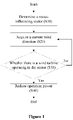
Figure 1 is a flowchart of a method for controlling noise of multiple wind turbines according to an embodiment of the present disclosure. - Reference is made to
Figure 1 . In step S10, a noise-influencing sector of each of the multiple wind turbines may be determined based on positions of the multiple wind turbines and a position of a noise-influencing site. - The noise-influencing site refers to a referential site (for example, a settlement) affected by the noise of the wind turbine. Generally, a noise influence on the noise-influencing site may be a superposed result of noise influences from two or more wind turbines on the noise-influencing site.
- Hereinafter determination of the noise-influencing sector is described in detail with reference to
Figure 2 . -
Figure 2 is a schematic diagram for determining a noise-influencing sector of a wind turbine based on a position of the wind turbine and a position of the noise-influencing site according to an embodiment of the present disclosure. - Based on a noise propagation theory of a wind turbine (hereinafter may be abbreviated as a turbine), a referential site in an upwind direction of the wind turbine is subjected to a minimum influence of noise, and a referential site in a downwind direction of the wind turbine is subjected to a maximum influence of noise. For example, as shown in
Figure 2 , the settlement 3 is more affected by the noise of a turbine T1 under the current wind direction (as indicated by 1 inFigure 2 ), in a case that the residential point 3 is located within the downwind direction of the turbine T1 (namely, the wind goes in a direction from the turbine T1 to the settlement 3). Additionally, as shown inFigure 2 , the settlement 3 is more affected by the noise of a turbine T2 under the current wind direction (as indicated by 2 inFigure 2 ), in a case that the residential point 3 is located within the downwind direction of the turbine T2 (namely, the wind goes in a direction from the turbine T2 to the settlement 3). Therefore, for wind turbines and a noise-influencing site that have been determined, each noise-influencing sector for each turbine on the noise-influencing site may be determined based on the positions of each turbine and the position of the noise-influencing site. - In some embodiments, the noise-influencing sector may be a sector region. A vertex of the sector region is the position of the wind turbine. A central angle of the sector region has a predetermined angle, and is formed with an angular bisector in a direction from the wind turbine to the noise-influencing site. Namely, the position of the wind turbine is an end point of the angular bisector, which is a ray, and a direction of the ray is along a connection line starting from the position of the wind turbine to the noise-influencing site.
- Reference is made to
Figure 2 . A sector region S1 may be formed by taking the position of the turbine T1 as the vertex, a connection line to the residential point 3 (as line L1 shown inFigure 2 ) as the angular bisector, and a predetermined angle θ1 as the central angle. The formed sector region S1 is the noise-influencing sector of the turbine T1. For example, the predetermined angle θ1 may be 60° or 90°, but is not limited thereto. - Similarly, a sector region S2 may be formed by taking the position of the turbine T2 as the vertex, a connection line to the residential point 3 (as line L2 shown in
Figure 2 ) as the angular bisector, and a predetermined angle θ2 as the central angle. The formed sector region S2 is the noise-influencing sector of the turbine T2. The predetermined angle θ1 and the predetermined angle θ2 may be identical or different. - Therefore, for different wind directions, in a case that each turbine operates within a range of the determined noise-influencing sector thereof (that is, a region in the downwind direction of the turbine is included in the noise-influencing sector of the turbine), noise of the corresponding turbine has a greater influence on a referential site in the range of the noise-influencing sector than a referential site out of the range of the noise-influencing sector.
- Reference is made to
Figure 1 again. In step S20, the current wind direction may be acquired. - For example, a referential direction of at least one wind turbine of the multiple turbines may be acquired via a satellite positioning-and-orientation system installed on the at least one wind turbine, and the current wind direction may be acquired in real time via the satellite positioning-and-orientation system and a yaw system of the turbine.
- Specifically, the referential direction of the at least one turbine (such as due north) may be acquired via the satellite positioning-and-orientation system, and the current wind direction may be acquired via the yaw system of the turbine based on the acquired referential direction. It should be noted that the above is an example, and embodiments of the present disclosure are not limited thereto.
- In step S30, it may be determined whether there is at least one wind turbine of the multiple wind turbines under the current wind direction operating in the noise-influencing sector of the at least one wind turbine. For example, as described above, it may be determined whether the downwind region of the turbines is included in the respective determined noise-influencing sector under the current wind direction.
- In a case that it is determined in the step S30 that the at least one wind turbine of the multiple wind turbines under the current wind direction operates in the noise-influencing sector thereof, output power of the at least one wind turbine may be limited in step S40. For example, in a case that five wind turbines of the multiple wind turbines operate in their respective noise-influencing sectors, the output power of the five wind turbines may be limited.
- In a case that it is determined in the step S30 that there is none of the multiple wind turbines operating in the noise-influencing sector, the method returns to step S20 and continues to acquire the current wind direction.
- In some embodiments, that the output power is limited may include following steps. A requirement on noise control at the noise-influencing site is acquired, and the requirement on noise control includes a level of a sound pressure at the noise-influencing site. The at least one wind turbine is operated in a power-limited mode corresponding to the requirement on noise control, so as to control the noise.
- Specifically, aerodynamic noise of the wind turbine in operation may be represented by a level Lω of sound power (in decibels (dB)). For a specific noise-influencing site, a noise level sensed at the noise-influencing site due to the aerodynamic noise of the turbine may be represented by the level Lρ (in decibels (dB)) of the sound pressure. For example, the maximum level of the bearable sound pressure at the noise-influencing site can be obtained by acquiring the requirement on noise control at the noise-influencing site.
- Magnitude of the level of the sound pressure is related to a distance to a sound source (for example, the turbine). Generally, for the turbine and the noise-influencing site with determined positions while neglecting complex terrain factors, the higher the level of the sound power of the turbine is, the higher the level of the sound pressure at the noise-influencing site is. Therefore, the level of the sound power of the turbine may be reduced by operating the turbine in the power-limited mode, and thereby the level of the sound pressure level at the noise-influencing site is reduced.
- In some embodiments, in a case that the at least one wind turbine operates in the power-limited mode, an impeller speed of the at least one wind turbine may be reduced and/or a minimum pitch angle may be increased, so that the measured level of the sound pressure at the noise-influencing site is less than or equal to a required level of the sound pressure. Those skilled in the art should appreciate that a specific power-limited mode of the present disclosure is not limited to the aforementioned manner that is determined according to the requirement on noise control. For example, the power-limited mode of the turbine may be set in advance.
- In some embodiments, a degree of reducing the impeller speed and/or increasing the minimum pitch angle may be determined based on a distance between the noise-influencing site and each of the at least one wind turbine. Namely, the farther the noise-influencing site is to the wind turbine, the less the impeller speed of the wind turbine is reduced and/or the minimum pitch angle of the wind turbine is increased. Therefore, a loss in overall power generation of the multiple wind turbines is reduced as much as possible, by reducing power of the wind turbine that is farther to the noise-influencing site less.
- After adjusting the impeller speed and/or the minimum pitch angel of each of the at least one wind turbine, the level of the sound pressure at the noise-influencing site may be measured, so as to determine whether a measured level of the sound pressure is less than or equal to the required level of the sound pressure at the noise-influencing site. In case of a positive determination, each turbine operates at the adjusted impeller speed and the adjusted minimum pitch angle, so as to ensure that the level of the sound pressure at the noise-influencing site in the noise-influencing sector meets the requirement.
- In a case that the measured level of the sound pressure is greater than the required level of the sound pressure level, the step of reducing the impeller speed and increasing the minimum pitch angle may be repeated on the at least one wind turbine, and the level of the sound pressure at the noise-influencing site may be measured again, until the level of the sound pressure is less than or equal to the required level of the sound pressure.
- In some embodiments, the output power of the at least one wind turbine reaches a rated power and is then increased, after the output power of the at least one wind turbine is limited. Or, output power of another wind turbine of the multiple wind turbines, which is not limited, reaches a rated power and is then increased, while the output power of the at least one wind turbine is limited. Thereby, a power loss in limiting the output power of the at least one wind turbine is compensated.
- Herein, being after the output power of the turbine is limited may refer to that the turbine goes out of the noise-influencing sector, or does not operate in the noise-influencing sector. Namely, a downwind region of the turbine is not included in the noise-influencing sector.
- For example, in a case that five wind turbines of the multiple wind turbines operate in the respective noise-influencing sector, the output power of the five wind turbines may reach a rated power and then be increased, after the five wind turbines go out of the respective noise-influencing sector. Or, output power of other wind turbines than the five wind turbines of the multiple wind turbines may reach a rated power and then be increased, while the output power of the five wind turbines is limited.
- In some embodiments, that the output power is increased may include a following step. The at least one wind turbine or the another wind turbine is operated in a power-boosted mode for power compensation.
- In a case that the wind turbine operates in the power-boosted mode, the impeller speed and/or the minimum pitch angle of the at least one wind turbine or the another wind turbine may be restored to a default value, and torque of a generator of the at least one wind turbine or the another wind turbine is set within a range between a respective rated value for the torque and a respective preset value for the torque, respectively, after the output power of the at least one wind turbine or the another wind turbine reaches the rated power. The respective preset value for the torque may be greater than the respective rated value for the torque.
- Specifically, the impeller speed and the minimum pitch angle of each of the at least one wind turbine or the another wind turbine may be firstly reset from a current value to the default value. The default value may refer to values of the impeller speed value and the minimum pitch angle of each turbine during normal operation that is prior to performing the method for controlling noise according to the present disclosure, namely, a design value of each turbine.
- In a case that the output power of each turbine reaches the rated power, since output power is directly proportional to the torque of the generator for each turbine, the torque of the generator may be increased to increase the output power of the turbine, consequently the output power can be above the rated power, so that supernumerary output power can be used to compensate for a loss in power generation during noise control in the corresponding noise-influencing sector. The preset value for the torque may be a value of the torque that enables the turbine to output the maximum power while ensuring safe operation, and the value may be set in advance. The preset value may be different for different turbines.
- For example, based on an amount of the loss in power generation during the turbine operates in the power-limited mode, it may be determined which value in the range between the rated value for the torque and the preset value for the torque is to be set. Those skilled in the art can understand that a manner of compensating the amount of power generation is not limited thereto. For example, the torque of the generator may be set to be any value in the range between the rated value for the torque and the preset value for the torque, or a length of time for operating in the power-boosted mode may be set.
- In some embodiments, the requirement on noise control may further include a length of time for operating in the power-limited mode and/or a time period for controlling noise. The time period for controlling noise refers to a time period in which the aerodynamic noise of the wind turbine is required to be controlled. For example, in a case that the requirement on noise control includes the time period for controlling noise, the output power of all the multiple wind turbines may be limited during the time period for controlling noise, until the time period for controlling noise ends. The step of limiting the output power may be similar to the step S40 in
Figure 1 . For example, the time period for controlling noise may be a time period from 21 p.m. to next 6 a.m., but is not limited thereto. -
Figure 3 is a flowchart of a method for controlling noise of multiple wind turbines according to another embodiment of the present disclosure. - Reference is made to
Figure 3 . According to another embodiment, step S310 is similar to step S10 ofFigure 1 , and the noise-influencing sector of each of the multiple wind turbines may be determined based on the positions of the multiple wind turbines and the position of the noise-influencing site. - In step S320, the current wind direction may be predicted by a predetermined period in advance. For example, a prediction model may be established in advance by using history data, and the determined prediction model may be used to predict the current wind direction by a predetermined period (such as 5 minutes) in advance.
- The step S330 is similar to the step S30 in
Figure 1 . It may be determined in advance whether there is at least one wind turbine of the multiple wind turbines under the current wind direction operating in the noise-influencing sector of the at least one wind turbine. - In a case that it is determined that the at least one turbine operates in the noise-influencing sector thereof, output power of the at least one wind turbine may be limited (namely, the at least one wind turbine operates in a power-limited mode) in step S340. In case of operating in the power-limited mode, an impeller speed of the at least one wind turbine is gradually decreased in advance and/or a minimum pitch angle of the at least one wind turbine is gradually increased in advance within the predetermined period. Thereby, the measured level of the sound pressure at the noise-influencing site is less than or equal to the required level of the sound pressure level, at a current time when the predetermined period ends.
- In addition, the output power of the at least one wind turbine or another wind turbine of the multiple wind turbines may further be increased (namely, the at least one wind turbine or the another wind turbine operates in a power-boosted mode) after reaching a rated power. In case of operating in the power-boosted mode, the impeller speed and/or the minimum pitch angle of the at least one wind turbine or the another wind turbine may be gradually restored in advance within the predetermined period. Thereby, the impeller speed and the minimum pitch angel are default values, at the current time when the predetermined period ends.
- Therefore, smooth switching between the power-limited operation and the power-boosted operation of the wind turbine can be realized. Instability due to an instant sudden switching can be prevented, and safe operation of the turbine can be further guaranteed.
- In addition, in a case that it is determined in the step S330 that there is no turbine operating in the noise-influencing sector, the method may return to the step S320 to continue predicting the current wind direction.
- In addition, a corresponding turbine may be set based on a prediction result to operate in one of the power-limited operation mode and the power-boosted operation mode, in a case that the predicted wind directions shows that fluctuations of the wind directions in the future would make the turbine operate unsteadily at a border of the noise-influencing sector (for example, alternating frequently between two conditions of operating and not operating in the noise-influencing sector). Thereby, it is prevented that stability and safety of the turbine are affected by adjusting parameters back and forth within a short period of time.
- In addition, it may be determined whether the current time after the predetermined period (such as 5 minutes, 10 minutes, or 60 minutes) would be within the controlling noise time period, in a case that the requirement on noise control includes the time period for controlling noise.
- The output power of all the multiple wind turbine may be limited, in a case that it is determined that the current time after the predetermined period is within the time period for controlling noise. The step of limiting the output power may be similar to the aforementioned.
-
Figure 4 is a flowchart of a method for controlling noise of multiple wind turbines according to another embodiment of the present disclosure. - Reference is made to
Figure 4 . A current wind speed may be acquired in step S401 before the noise-influencing sector is determined in step S410. For example, a variety of conventional methods can be used to acquire the current wind speed. - In step S402, it may be determined whether the acquired current wind speed is out of a predetermined range of a wind speed.
- For example, the predetermined range of the wind speed may be a wind speed range between a first wind speed and a second wind speed. The turbine is in a variable-rotor-speed control stage in a case that the wind speed is less than the first wind speed (for example, 6 m/s). In such case, the impeller speed is low, the generated aerodynamic noise is low, and there is no need to control the noise of the turbine. Environmental noise is generally much larger than the noise generated by the turbine in a case that the wind speed is greater than the second wind speed (for example, 12 m/s), and there is no practical significance in controlling noise of the turbine.
- Therefore, the wind turbine may normally operate without performing noise control in a case that it is determined in the step S402 that the current wind speed is out of the predetermined range of the wind speed. Otherwise, the method continues to perform steps S410 to S440. Herein steps S410 to S440 are similar to the steps S10 to S40 in
Figure 1 , respectively. - In some embodiments, in the step S401, the predetermined prediction model as described in
Figure 3 may be used to predict the current wind speed by the predetermined period in advance. - It should be noted that no noise control is performed on the multiple wind turbines, in a case that it is determined in the step S402 that the acquired current wind speed is out of the predetermined range of the wind speed. Namely, the multiple wind turbines operate normally and a method for controlling noise is not performed, regardless whether the current time is within the time period for controlling noise and whether the wind turbine operates in the noise-influencing sector.
-
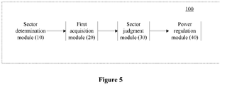
Figure 5 is a structural block diagram of an apparatus for controlling noise of multiple wind turbines according to an embodiment of the present disclosure. - Reference is made to
Figure 5 . Theapparatus 100 according to the embodiment may include asector determination module 10, afirst acquisition module 20, a sector judgment module 30, and apower regulation module 40. - The
sector determination module 10 may determine a noise-influencing sector of the each of the multiple wind turbines based on positions of the multiple wind turbines and a position of the noise-influencing site. - The noise-influencing site refers to a referential site (for example, a settlement) affected by the noise of the wind turbine. Generally, a noise influence on the noise-influencing site may be a superposed result of noise influences from two or more wind turbines on the noise-influencing site. The noise-influencing sector may be a sector region. A vertex of the sector region is the position of the wind turbine. A central angle of the sector region has a predetermined angle, and is formed with an angular bisector in a direction from the wind turbine to the noise-influencing site.
- The
first acquisition module 20 may acquire a current wind direction. - For example, the
first acquisition module 20 may acquire a referential direction of the at least one wind turbine via a satellite positioning-and-orientation system installed on the al least one wind turbine of the multiple wind turbines, and acquire the current wind direction via the satellite positioning-and-orientation system and a yaw system of the turbine. - Specifically, the
first acquisition module 20 may acquire the referential direction (such as due north) of the at least one wind turbine via the satellite positioning-and-orientation system, and acquire the current wind direction via the yaw system of the turbine based on the acquired referential direction. It should be noted the above is an example, and embodiments of the present disclosure are not limited thereto. - The sector judgment module 30 may determine whether there is at least one wind turbine of the multiple wind turbines under the current wind direction operating in the noise-influencing sector of the at least one wind turbine. For example, the sector judgment module 30 may determine whether a downwind region of the turbine is included in the noise-influencing sector of the turbine under the current wind direction.
- In a case that the sector judgment module 30 determines that there is at least one wind turbine of the multiple wind turbines operating in the noise-influencing sector of the at least one wind turbine, the
power regulation module 40 may limit the output power of the at least one wind turbine. - In a case that the sector judgment module 30 determines that there is no wind turbine operating in the noise-influencing sector, the
first acquisition module 20 may continue acquiring the current wind direction. - In some embodiments, limiting the output power may include following steps. A requirement on noise control at the noise-influencing site is acquired, and the requirement on noise control includes a level of a sound pressure at the noise-influencing site. The at least one wind turbine is operated in a power-limited mode corresponding to the requirement on noise control, so as to control the noise.
- In some embodiments, the
power regulation module 40 may reduce an impeller speed and/or increase a minimum pitch angle of the at least one wind turbine, in a case that the at least one wind turbine operates in the power-limited mode, so that a measured level of the sound pressure is less than or equal to a required level of the sound pressure at the noise-influencing site. A degree of reducing the impeller speed and/or increasing the minimum pitch angle may be determined based on a distance between the noise-influencing site and each of the at least one wind turbine. The farther the noise-influencing site is to the wind turbine, the less the impeller speed of the wind turbine is reduced and/or the minimum pitch angle of the wind turbine is increased. A specific description of limiting the output power has been provided in the above description and is not repeated herein. - In some embodiments, the output power of the at least one wind turbine reaches a rated power and then is increased by the
power regulation module 40, after limiting the output power of the at least one wind turbine. Or, output power of another wind turbine of the multiple wind turbines, which is not limited, reaches a rated power and then is increased by thepower regulation module 40, while limiting the output power of the at least one wind turbine. Thereby, a power loss in limiting the output power of the at least one wind turbine is compensated. - Herein, being after the output power of the turbine is limited may refer to that the turbine goes out of the noise-influencing sector, or does not operate in the noise-influencing sector. Namely, a downwind region of the turbine is not included in the noise-influencing sector.
- In some embodiments, increasing the output power may include a following step. The at least one wind turbine or the another wind turbine is operated in a power-boosted mode for power compensation.
- The power regulation module may restore the impeller speed and/or the minimum pitch angle of the at least one wind turbine or the another wind turbine to a default value, and set torque of a generator of the at least one wind turbine or the another wind turbine within a range between a respective rated value for the torque and a respective preset value for the torque, respectively, after the at least one wind turbine or the another wind turbine reaches the rated power, in a case that the at least one wind turbine or the another wind turbine operates in the power-boosted mode. The respective preset value for the torque may be greater than the respective rated value for the torque. A specific description of increasing the output power has been provided in the above description and is not repeated herein.
- The requirement on noise control may further include a length of time for operating in the power-limited mode and/or a time period for controlling noise.
- In some embodiments, the step of acquiring the current wind direction by the
first acquisition module 20 may include a following step. The current wind direction is predicted by a predetermined period in advance. - The sector judgment module 30 may determine in advance whether there is at least one wind turbine of the multiple wind turbines under the predicted wind direction operates in the noise-influencing sector thereof determined by the
sector determination module 10. - In a case that the determination is positive, the
power regulation module 40 may limit the output power of the at least one wind turbine (namely, the at least one wind turbine operates in a power-limited mode). In case of operating in the power-limited mode, an impeller speed of the at least one wind turbine may be gradually decreased in advance and/or a minimum pitch angle of the at least one wind turbine may be gradually increased in advance within the predetermined period. Thereby, the measured level of the sound pressure at the noise-influencing site is less than or equal to the required level of the sound pressure level, at a current time when the predetermined period ends. - The
power regulation module 40 may increase the output power of the at least one wind turbine or another wind turbine of the multiple wind turbines, after the output power reaches the rated power (namely, the at least one wind turbine or the another wind turbine operates in a power-boosted mode). In case of operating in the power-boosted mode, the impeller speed and/or the minimum pitch angle of the at least one wind turbine or the another wind turbine may be gradually restored in advance within the predetermined period. Thereby, the impeller speed and the minimum pitch angel are default values, at the current time when the predetermined period ends. - Therefore, smooth switching between the power-limited operation and the power-boosted operation of the turbine can be realized. Instability due to an instant sudden switching can be prevented, and safe operation of the turbine can be further guaranteed.
- In addition, the
first acquisition module 20 may continue acquiring (predicting) the current wind direction, in a case that there is no turbine operating in the noise-influencing sector. - In some embodiments, the
apparatus 100 may further include a time period judgment module (not shown in the figure). The time period judgment module may determine whether the current time after the predetermined period (such as 5 minutes, 10 minutes, or 60 minutes) would be within a time period for controlling noise, in a case that the requirement on noise control includes the time period for controlling noise. - For example, the
power regulation module 40 reduces the output power of all the multiple wind turbines until the time period for controlling noise ends, in a case that the time period judgment module determines that the current time after the predetermined period is within the time period for controlling noise. - In some embodiments, the
power regulation module 40 may reduce the impeller speed and/or increase the minimum pitch angle of each of the multiple wind turbine, so that a measured level of the sound pressure is less than or equal to a required level of sound power in the time period for controlling noise at the noise-influencing site. - In some embodiments, the
apparatus 100 may further include a second acquisition module (not shown in the figure) and an operation control module (not shown in the figure). The second acquisition module may acquire a current wind speed before thesector determination module 10 determines the noise-influencing sector. An operation control module may operate all the multiple wind turbines normally and theapparatus 100 does not control the noise, in a case that the current wind speed acquired by the second acquisition module is out of a predetermined range of a wind speed. -
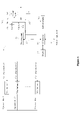
Figure 6 is a schematic diagram of a system for controlling noise of wind turbines according to an exemplary embodiment of the present application. - As shown in
Figure 6 , the system for controlling noise of wind turbines may include multiple wind turbines (namely,wind turbine 1,wind turbine 2,. , wind turbine n) and a farm-level controller 50 (such as a field-group controller). In some embodiments, components of the farm-level controller 50 may include but are not limited to: one or more processors orprocessing units 501, asystem memory 502, and abus 503 connecting different system components (including thesystem memory 502 and the processing unit 501). - The
bus 503 represents one or more of multiple bus structures. For example, the bus structures include but are not limited to: an Industry Standard Architecture (ISA) bus, a Micro Channel architecture (MCA) bus, an enhanced ISA bus, a Video Electronics Standards Association (VESA) local area bus, and a Peripheral Component Interconnect (PCI) bus. - In some embodiments, the farm-
level controller 50 may further include one or more computer-system-readable media. The media may be any available media accessible to the fieldgroup control device 50, including volatile and non-volatile media, removable or immovable media. - The
system memory 502 may include the computer-system-readable medium in the form of a volatile memory, such as a random access memory (RAM) 504 and/or acache memory 505. Thesystem memory 502 may further include other removable or immovable, volatile or non-volatile computer system storage media. For example, thesystem memory 502 may further include astorage system 506, and thestorage system 506 may be used to read and write immovable, non-volatile magnetic media (not shown inFigure 6 , commonly called a "hard disk drive"). Although not shown inFigure 6 , thesystem memory 502 may further include a disk drive for reading and writing a removable non-volatile disk (such as a floppy disk), and an optical disk drive for reading and writing a removable non-volatile optical disc (such as a CD-ROM, DVD-ROM, or another optical medium). In such cases, each drive may be connected to thebus 503 via one or more data media interfaces. Thesystem memory 502 may include at least one program product, and the program product is provided with at least oneprogram module 507 configured to perform multiple functions according to embodiments of the present disclosure. - A program/
utility 508 provided with the at least oneprogram module 507 may be stored in, for example, thesystem memory 502. Theprogram module 507 includes but is not limited to: an operating system, one or more applications, other program modules and program data. In addition, each or a combination of the examples may include an implementation of a network environment. Generally, theprogram module 507 performs the functions and/or methods according to the embodiments described herein, so that at least one of the multiple wind turbines executes a noise control strategy determined for it. - The farm-
level controller 50 may communicate with adisplay 60 and one or more other external devices 70 (such as a keyboard and a pointing device), and may communicate with one or more devices that enable a user to interact with the farm-level controller 50 and/or with any device that enables the farm-level controller 50 to communicate with one or more other computing devices (for example, a network card and a modem). Such communication may be realized via an input/output (I/O)interface 509. In addition, the farm-level controller 50 may communicate with one or more networks (such as a local area network (LAN), a wide area network (WAN) and/or a public network (such as the Internet)) via anetwork adapter 510. As shown inFigure 6 , thenetwork adapter 510 may communicate with other modules of the farm-level controller 50 via thebus 503. It should be understood that, although not shown inFigure 6 , other hardware and/or software modules may be used in conjunction with the computer system, which include but are not limited to: a microcode, a device driver, a redundant processing unit, an external disk drive array, a RAID system, a tape drive, and a data backup storage system. - It should be noted that
Figure 6 illustratively shows a schematic diagram of a farm-level controller 50 that may be configured to implement the various embodiments of the present application. It can be appreciated by those skilled in the art that the farm-level controller 50 may be implemented by a control device that exists in a control system of a current wind turbine, may be implemented by an additional control device that is introduced, or may be implemented together by the control device that exists in the control system of the wind turbine and the additional device. - Based on the method and the apparatus for controlling noise of the multiple wind turbines according to the embodiments of the present disclosure, an operation mode of the wind turbine can be reasonably switched by delimiting the noise-influencing sector of each of the multiple wind turbines. The wind turbine is controlled to meet a restraint on the noise while compensating a loss in power generation due to the noise control. Thereby, benefits of wind farms are improved, and requirements on various customizations are met.
- Although the present disclosure has been shown and described in detail with reference to the exemplary embodiments of the present disclosure, those skilled in the art should understand that the present disclosure can be modified in forms and details without departing from the scope of the present disclosure as defined by the claim
Claims (15)
- A method for controlling noise of a plurality of wind turbines, comprising:determining (S10) a noise-influencing sector of each of the plurality of wind turbines respectively, based on a position of each of the plurality of wind turbines and a position of a noise-influencing site;acquiring (S20) a current wind direction;determining (S30) whether there is at least one wind turbine of the plurality of wind turbines under the current wind direction operating in the noise-influencing sector of the at least one wind turbine;limiting (S40) output power of the at least one wind turbine, in a case that the determination is positive; andcontinuing to acquire (S20) the current wind direction again, in a case (S30) that the determination is negative;wherein the output power of the at least one wind turbine reaches a rated power and is then increased after limiting (S40) the output power of the at least one wind turbine, or output power of another wind turbine of the plurality of wind turbines which is not limited reaches the rated power and is then increased while limiting (S40) the output power of the at least one wind turbine, so as to compensate a power loss in limiting (S40) the output power of the at least one wind turbine;and the noise-influencing site is a referential site affected by noise of the plurality of wind turbines;wherein the noise-influencing sector is a sector region (S1, S2);a vertex of the sector region (S1, S2) is the position of the wind turbines; anda central angle of the sector region (S1, S2) has a predetermined angle (θ1, θ2), and an angular bisector of the central angle is in a direction from the wind turbine to the noise-influencing site.
- The method according to claim 1, wherein limiting (S40) the output power comprises:acquiring a requirement on noise control at the noise-influencing site, wherein the requirement on noise control comprises a level of a sound pressure at the noise-influencing site; andoperating the at least one wind turbine in a power-limited mode corresponding to the requirement on noise control, so as to the control the noise.
- The method according to claim 2, wherein:an impeller speed of the at least one wind turbine is reduced and/or a minimum pitch angle of the at least one wind turbine is increased in a case that the wind turbine operates in the power-limited mode, so that a measured level of the sound pressure at the noise-influencing site is less than or equal to a required level of the sound pressure at the noise-influencing site; anda degree of reducing the impeller speed and/or increasing the minimum pitch angle for each of the at least one wind turbine is determined based on a distance between the noise-influencing site and the corresponding wind turbine of the at least one wind turbine.
- The method according to claim 1, wherein increasing the output power comprises:
operating the at least one or the another wind turbine in a power-boosted mode for power compensation. - The method according to claim 4, wherein in a case that the at least one wind turbine or the another wind turbine operates in the power-boosted mode:the impeller speed and/or the minimum pitch angle of the at least one wind turbine or the another wind turbine is restored to a default value; andthe torque of a generator of the at least one wind turbine or the another wind turbine is set within a range between a respective rated value for the torque and a respective preset value for the torque, respectively, after the output power of the at least one wind turbine or the another wind turbine reaches the rated power, wherein the respective preset value for the torque is greater than the respective rated value for the torque.
- The method according to claims 3 or 5, wherein acquiring (S20) the current wind direction comprises:predicting (S320) the current wind direction by a predetermined period in advance; andwherein:the impeller speed of the at least one wind turbine is gradually decreased in advance within the predetermined period and/or the minimum pitch angle of the at least one wind turbine is gradually increased in advance within the predetermined period, in a case that the wind turbine operates in the power-limited mode, so that the measured level of the sound pressure at the noise-influencing site is less than or equal to the required level of the sound pressure level at the noise-influencing site at a current time when the predetermined period ends; andthe impeller speed and/or the minimum pitch angle of the at least one wind turbine or the another wind turbine is gradually restored in advance within the predetermined period, in a case that the wind turbine operates in the power-boosted mode, so that the impeller speed and the minimum pitch angle of the at least one wind turbine or the another wind turbine are default values at the current time when the predetermined period ends.
- The method according to claim 1, further comprising:acquiring (S401) a current wind speed, before determining (S410) the noise-influencing sector; andoperating the plurality of wind turbines normally without controlling the noise, in a case (S402) that the current wind speed is out of a predetermined range of a wind speed.
- An apparatus (100) for controlling noise of a plurality of wind turbines, comprising:a sector determination module (10), configured to determine a noise-influencing sector of each of the plurality of wind turbines respectively based on a position of each of the plurality of wind turbines and a position of a noise-influencing site;a first acquisition module (20), configured to acquire a current wind direction;a sector judgment module (30), configured to determine whether there is at least one wind turbine of the plurality of wind turbines under the current wind direction operating in the noise-influencing sector of the at least one wind turbine; anda power regulation module (40), configured to limit output power of the wind turbine, in a case that the at least one wind turbine of the plurality of wind turbines operates in the noise-influencing sector of the at least one wind turbine;wherein first acquisition module (20) acquires the current wind direction again, in a case that there is none of the plurality of wind turbines operating in the noise-influencing sector; andwherein the output power of the at least one wind turbine reaches a rated power and then is increased by the power regulation module (40) after limiting the output power of the at least one wind turbine, or output power of another wind turbine of the plurality of wind turbines, which is not limited, reaches the rated power and then is increased by the power regulation module (40) while limiting the output power of the at least one wind turbine, so as to compensate a power loss in limiting the output power of the at least one wind turbine;and the noise-influencing site is a referential site affected by noise of the plurality of wind turbines;wherein the noise-influencing sector is a sector region (S1, S2);a vertex of the sector region (S1, S2) is the position of the wind turbine; anda central angle of the sector region (S1, S2) has a predetermined angle (θ1, θ2), and an angular bisector of the central angle is in a direction from the wind turbine to the noise-influencing site.
- The apparatus (100) according to claim 8, wherein limiting the output power comprises:acquiring a requirement on noise control at the noise-influencing site, wherein the requirement on noise control comprises a level of a sound pressure at the noise-influencing site; andoperating the at least one wind turbine in a power-limited mode corresponding to the requirement on noise control, so as to control the noise.
- The apparatus (100) according to claim 9, wherein:an impeller speed of the at least one wind turbine is reduced and/or a minimum pitch angle of the at least one wind turbine is increased, in a case that the wind turbine operates in the power-limited mode, so that a measured level of the sound pressure at the noise-influencing site is less than or equal to a required level of the sound pressure at the noise-influencing site; anda degree of reducing the impeller speed and/or increasing the minimum pitch angle for each of the at least one wind turbine is determined based on a distance between the noise-influencing site and the corresponding wind turbine of the at least one wind turbine.
- The apparatus (100) according to claim 8, wherein increasing the output power comprises:operating the at least one wind turbine or the another wind turbine in a power-boosted mode for power compensation; andwherein in a case that the at least one wind turbine or the another wind turbine operates in the power-boosted mode:the impeller speed and/or the minimum pitch angle of the wind turbine of the at least one wind turbine or the another wind turbine is restored to a default value; andthe torque of a generator of the at least one wind turbine or the another wind turbine is set within a range between a respective rated value for the torque and a respective preset value for the torque, respectively, after the at least one wind turbine or the another wind turbine reaches the rated power, wherein the respective preset value for the torque is greater than the respective rated value for the torque.
- The apparatus (100) according to claims 10 or 11, wherein acquiring (S20) the current wind direction comprises:Predicting (S320) the current wind direction by a predetermined period in advance; andwherein:the impeller speed of the at least one wind turbine is gradually decreased in advance within the predetermined period and/or the minimum pitch angle of the at least one wind turbine is gradually increased in advance within the predetermined period, in a case that the wind turbine operates in the power-limited mode, so that the measured level of the sound pressure at the noise-influencing site is less than or equal to the required level of the sound pressure level at the noise-influencing site at a current time when the predetermined period ends; andthe impeller speed and/or the minimum pitch angle of the at least one wind turbine or the another wind turbine is gradually restored in advance within the predetermined period, in a case that the wind turbine operates in the power-boosted mode, so that the impeller speed and the minimum pitch angle of the at least one wind turbine or the another wind turbine are default values at the current time when the predetermined period ends.
- The apparatus (100) according to claim 8, further comprising:a second acquisition module, configured to acquire (S401) a current wind speed before the sector determination module (10) determines (S410) the noise-influencing sector; andan operation control module, configured to operate the plurality of wind turbines normally without controlling the noise, in a case (S402) that the current wind speed acquired by the second acquisition module is out of a predetermined range of a wind speed.
- A computer-readable storage medium, storing a computer program, wherein:
the computer program comprises instructions which, when the computer program is executed by a processor, causes a computer to perform the method for controlling noise of the plurality of wind turbines according to any one of claims 1 to 5 and 7. - A controller (50) of a wind turbine, comprising:a processor (501); anda memory (502) storing a computer program (508), wherein:
the computer program (508) comprises instructions which, when the computer program (508) is executed by a processor (501), causes a computer to perform the method for controlling noise of the plurality of wind turbines according to any one of claims 1 to 5 and 7.
Applications Claiming Priority (2)
| Application Number | Priority Date | Filing Date | Title |
|---|---|---|---|
| CN201810482517.7A CN110500233B (en) | 2018-05-18 | 2018-05-18 | Method and device for noise control of a plurality of wind energy installations |
| PCT/CN2018/108668 WO2019218575A1 (en) | 2018-05-18 | 2018-09-29 | Method and device for noise control of a plurality of wind turbine generator systems |
Publications (3)
| Publication Number | Publication Date |
|---|---|
| EP3587802A1 EP3587802A1 (en) | 2020-01-01 |
| EP3587802A4 EP3587802A4 (en) | 2021-01-20 |
| EP3587802B1 true EP3587802B1 (en) | 2022-06-22 |
Family
ID=67437557
Family Applications (1)
| Application Number | Title | Priority Date | Filing Date |
|---|---|---|---|
| EP18893345.1A Active EP3587802B1 (en) | 2018-05-18 | 2018-09-29 | Method and device for noise control of a plurality of wind turbine generator systems |
Country Status (5)
| Country | Link |
|---|---|
| US (1) | US11566602B2 (en) |
| EP (1) | EP3587802B1 (en) |
| CN (1) | CN110500233B (en) |
| AU (1) | AU2018400527B2 (en) |
| WO (1) | WO2019218575A1 (en) |
Families Citing this family (2)
| Publication number | Priority date | Publication date | Assignee | Title |
|---|---|---|---|---|
| CN113027675B (en) * | 2019-12-24 | 2022-11-25 | 北京金风科创风电设备有限公司 | Control method and control device for wind power plant and wind generating set |
| CN113757050B (en) * | 2021-09-08 | 2023-05-02 | 浙江运达风电股份有限公司 | Wind farm noise monitoring control system and method |
Citations (8)
| Publication number | Priority date | Publication date | Assignee | Title |
|---|---|---|---|---|
| JP2005036749A (en) | 2003-07-17 | 2005-02-10 | Fuji Heavy Ind Ltd | Horizontal axis windmill and its control method |
| EP2216549A2 (en) | 2009-02-10 | 2010-08-11 | General Electric Company | Wind turbine noise control |
| WO2013044925A1 (en) | 2011-09-30 | 2013-04-04 | Vestas Wind Systems A/S | Control of wind turbines |
| EP2599996A1 (en) | 2011-12-02 | 2013-06-05 | Vestas Wind Systems A/S | Controlling of noise emission of a wind park |
| US20130154263A1 (en) | 2011-12-20 | 2013-06-20 | Sid Ahmed ATTIA | Method and system for noise-controlled operation of a wind turbine |
| WO2016082838A1 (en) | 2014-11-24 | 2016-06-02 | Vestas Wind Systems A/S | Determination of wind turbine configuration |
| WO2017000956A1 (en) | 2015-06-30 | 2017-01-05 | Vestas Wind Systems A/S | Control of a wind park to optimise power production during reduced noise operation |
| WO2017054822A1 (en) | 2015-09-29 | 2017-04-06 | Vestas Wind Systems A/S | Boost and regulation groups for wind power plant |
Family Cites Families (28)
| Publication number | Priority date | Publication date | Assignee | Title |
|---|---|---|---|---|
| EP1192355B2 (en) * | 1999-06-10 | 2015-10-21 | Aloys Wobben | Wind energy system with adjustment of the sound level |
| JP4637419B2 (en) | 2001-09-21 | 2011-02-23 | 富士重工業株式会社 | Wind generator operation control method |
| ES2261100B1 (en) * | 2006-03-29 | 2007-08-01 | Gamesa Corporacion Tecnologica, S.A. | ANTI-NOISE AEROGENERATOR. |
| ES2357077T3 (en) * | 2007-05-31 | 2011-04-18 | Vestas Wind Systems A/S | PROCEDURE FOR THE OPERATION OF A WIND TURBINE, WIND TURBINE AND USE OF THE PROCEDURE. |
| US8050899B2 (en) * | 2008-05-30 | 2011-11-01 | General Electric Company | Method for wind turbine placement in a wind power plant |
| WO2010037387A2 (en) * | 2008-09-30 | 2010-04-08 | Vestas Wind Systems A/S | Control of wind park noise emission |
| US8128361B2 (en) * | 2008-12-19 | 2012-03-06 | Frontier Wind, Llc | Control modes for extendable rotor blades |
| US7896613B2 (en) | 2009-06-03 | 2011-03-01 | General Electric Company | System and method for wind turbine noise control and damage detection |
| US7902689B2 (en) * | 2009-07-07 | 2011-03-08 | General Electric Company | Method and system for noise controlled operation of a wind turbine |
| US8215907B2 (en) * | 2009-09-30 | 2012-07-10 | General Electric Company | Method and apparatus for controlling acoustic emissions of a wind turbine |
| KR101180347B1 (en) * | 2010-10-29 | 2012-09-06 | (주)하이레벤 | a system to reduce vibration-noise of wind turbine |
| US20110223006A1 (en) * | 2010-12-06 | 2011-09-15 | Friedrich Loh | System, device, and method for noise-based operation of wind turbines |
| US8232663B2 (en) * | 2011-06-30 | 2012-07-31 | General Electric Company | Controlling noise generated by wind turbines in a wind farm by de-synchronization of wind turbine rotors |
| US8287228B2 (en) * | 2011-06-30 | 2012-10-16 | General Electric Company | System and methods for controlling the amplitude modulation of noise generated by wind turbines |
| US8304926B2 (en) * | 2011-09-16 | 2012-11-06 | General Electric Company | Wind turbine sound management |
| EP2610484A1 (en) | 2011-12-26 | 2013-07-03 | Vestas Wind Systems A/S | Method for controlling a wind turbine |
| EP2626550B1 (en) | 2012-02-10 | 2016-04-27 | Siemens Aktiengesellschaft | Improved noise reduction control for wind turbines |
| CA2898915C (en) * | 2014-07-31 | 2022-10-25 | General Electric Company | System and method for optimal operation of wind farms |
| US9347432B2 (en) * | 2014-07-31 | 2016-05-24 | General Electric Company | System and method for enhanced operation of wind parks |
| US9995277B2 (en) * | 2014-07-31 | 2018-06-12 | General Electric Company | System and method for controlling the operation of wind turbines |
| DK3073108T3 (en) * | 2015-03-27 | 2020-01-06 | Siemens Gamesa Renewable Energy As | Steering for a wind turbine |
| US10024304B2 (en) * | 2015-05-21 | 2018-07-17 | General Electric Company | System and methods for controlling noise propagation of wind turbines |
| DE102015114958A1 (en) * | 2015-09-07 | 2017-03-09 | Wobben Properties Gmbh | Method for operating a wind farm |
| AT15428U1 (en) * | 2016-03-16 | 2017-08-15 | Uptime Holding Gmbh | Method for determining the wind speed and installation for carrying it out |
| CN109312714B (en) * | 2016-04-07 | 2021-05-04 | 维斯塔斯风力系统集团公司 | Control of a wind turbine taking noise into account |
| WO2017198271A1 (en) * | 2016-05-18 | 2017-11-23 | Vestas Wind Systems A/S | Controlling wind turbine noise |
| US10247171B2 (en) | 2016-06-14 | 2019-04-02 | General Electric Company | System and method for coordinating wake and noise control systems of a wind farm |
| CN114757420A (en) * | 2018-10-31 | 2022-07-15 | 北京金风科创风电设备有限公司 | Wind power plant noise prediction method, device and system |
-
2018
- 2018-05-18 CN CN201810482517.7A patent/CN110500233B/en active Active
- 2018-09-29 WO PCT/CN2018/108668 patent/WO2019218575A1/en unknown
- 2018-09-29 US US16/477,384 patent/US11566602B2/en active Active
- 2018-09-29 EP EP18893345.1A patent/EP3587802B1/en active Active
- 2018-09-29 AU AU2018400527A patent/AU2018400527B2/en active Active
Patent Citations (8)
| Publication number | Priority date | Publication date | Assignee | Title |
|---|---|---|---|---|
| JP2005036749A (en) | 2003-07-17 | 2005-02-10 | Fuji Heavy Ind Ltd | Horizontal axis windmill and its control method |
| EP2216549A2 (en) | 2009-02-10 | 2010-08-11 | General Electric Company | Wind turbine noise control |
| WO2013044925A1 (en) | 2011-09-30 | 2013-04-04 | Vestas Wind Systems A/S | Control of wind turbines |
| EP2599996A1 (en) | 2011-12-02 | 2013-06-05 | Vestas Wind Systems A/S | Controlling of noise emission of a wind park |
| US20130154263A1 (en) | 2011-12-20 | 2013-06-20 | Sid Ahmed ATTIA | Method and system for noise-controlled operation of a wind turbine |
| WO2016082838A1 (en) | 2014-11-24 | 2016-06-02 | Vestas Wind Systems A/S | Determination of wind turbine configuration |
| WO2017000956A1 (en) | 2015-06-30 | 2017-01-05 | Vestas Wind Systems A/S | Control of a wind park to optimise power production during reduced noise operation |
| WO2017054822A1 (en) | 2015-09-29 | 2017-04-06 | Vestas Wind Systems A/S | Boost and regulation groups for wind power plant |
Non-Patent Citations (2)
| Title |
|---|
| ANONYMOUS: "Technische Beschreibung ENERCON Windenergieanlagen Schalloptimierung", ENERCON, 26 November 2012 (2012-11-26), pages 1 - 7, XP093085244 |
| ANONYMOUS: "Wind farms noise impact: theory and regulations", SIXENSE ENVIOMENT, 8 March 2017 (2017-03-08), pages 1 - 13, XP093085925 |
Also Published As
| Publication number | Publication date |
|---|---|
| CN110500233A (en) | 2019-11-26 |
| AU2018400527A1 (en) | 2019-12-05 |
| US20210332793A1 (en) | 2021-10-28 |
| WO2019218575A1 (en) | 2019-11-21 |
| EP3587802A4 (en) | 2021-01-20 |
| EP3587802A1 (en) | 2020-01-01 |
| US11566602B2 (en) | 2023-01-31 |
| CN110500233B (en) | 2020-07-07 |
| AU2018400527B2 (en) | 2020-09-10 |
Similar Documents
| Publication | Publication Date | Title |
|---|---|---|
| US11002249B2 (en) | Primary frequency modulation method and device for wind turbine | |
| EP3779184B1 (en) | Yaw control method, device and system for wind turbine | |
| EP3587802B1 (en) | Method and device for noise control of a plurality of wind turbine generator systems | |
| CN107559144B (en) | Method and system for feed-forward control of a wind turbine | |
| EP3594489B1 (en) | Noise control method and device for wind power generator set | |
| Jiang et al. | A comparative study of shutdown procedures on the dynamic responses of wind turbines | |
| CN109958576B (en) | Method and device for controlling rotating speed of wind generating set | |
| CN109185208B (en) | Fan speed regulation method and related device | |
| CN111472931B (en) | Wind power generator, control method and device thereof, and computer readable storage medium | |
| JP2010127235A (en) | Windmill arrangement determining device, windmill arrangement determining program, and recording medium | |
| CN111577542A (en) | Noise control method, device, equipment and medium for wind turbine generator | |
| CN111456899A (en) | Minimum headroom control system, method, electronic device, and storage medium | |
| CN115370429A (en) | High-temperature gas cooled reactor steam turbine control method and device and storage medium | |
| AU2022352515A1 (en) | Wind-storage combined frequency regulation method and wind-storage combined frequency regulation apparatus | |
| CN110943480A (en) | Power system frequency modulation method and device, computer equipment and storage medium | |
| Louazel et al. | Impact of a wind turbine blade pitch rate on a floating wind turbine during an emergency shutdown operation | |
| CN117231418A (en) | Method and system for limiting load reduction of My (My) of fixed hub of wind generating set | |
| CN116345569A (en) | Frequency modulation performance index optimization method and device of hydroelectric generating set and electronic equipment | |
| CN116642268A (en) | Control method, system, equipment and storage medium of water heater | |
| CN116164424A (en) | Water heater and combustion control method, system and storage medium thereof | |
| CN115898760A (en) | Wind turbine generator load control method and device, computer readable medium and equipment | |
| CN116205690A (en) | Block chain-based power transaction quotation method and device and electronic equipment | |
| CN117869221A (en) | Wind generating set safety control method, system and equipment based on blade tip clearance | |
| CN114439681A (en) | Power improving method and device for wind generating set | |
| CN116154818A (en) | Cooperative control method and device for energy storage system and wind turbine generator set and electronic equipment |
Legal Events
| Date | Code | Title | Description |
|---|---|---|---|
| STAA | Information on the status of an ep patent application or granted ep patent |
Free format text: STATUS: UNKNOWN |
|
| STAA | Information on the status of an ep patent application or granted ep patent |
Free format text: STATUS: THE INTERNATIONAL PUBLICATION HAS BEEN MADE |
|
| PUAI | Public reference made under article 153(3) epc to a published international application that has entered the european phase |
Free format text: ORIGINAL CODE: 0009012 |
|
| STAA | Information on the status of an ep patent application or granted ep patent |
Free format text: STATUS: REQUEST FOR EXAMINATION WAS MADE |
|
| 17P | Request for examination filed |
Effective date: 20190705 |
|
| AK | Designated contracting states |
Kind code of ref document: A1 Designated state(s): AL AT BE BG CH CY CZ DE DK EE ES FI FR GB GR HR HU IE IS IT LI LT LU LV MC MK MT NL NO PL PT RO RS SE SI SK SM TR |
|
| STAA | Information on the status of an ep patent application or granted ep patent |
Free format text: STATUS: REQUEST FOR EXAMINATION WAS MADE |
|
| R17P | Request for examination filed (corrected) |
Effective date: 20190705 |
|
| A4 | Supplementary search report drawn up and despatched |
Effective date: 20201221 |
|
| RIC1 | Information provided on ipc code assigned before grant |
Ipc: F03D 7/00 20060101AFI20201215BHEP |
|
| STAA | Information on the status of an ep patent application or granted ep patent |
Free format text: STATUS: EXAMINATION IS IN PROGRESS |
|
| 17Q | First examination report despatched |
Effective date: 20210507 |
|
| GRAP | Despatch of communication of intention to grant a patent |
Free format text: ORIGINAL CODE: EPIDOSNIGR1 |
|
| STAA | Information on the status of an ep patent application or granted ep patent |
Free format text: STATUS: GRANT OF PATENT IS INTENDED |
|
| INTG | Intention to grant announced |
Effective date: 20220215 |
|
| GRAS | Grant fee paid |
Free format text: ORIGINAL CODE: EPIDOSNIGR3 |
|
| GRAA | (expected) grant |
Free format text: ORIGINAL CODE: 0009210 |
|
| STAA | Information on the status of an ep patent application or granted ep patent |
Free format text: STATUS: THE PATENT HAS BEEN GRANTED |
|
| AK | Designated contracting states |
Kind code of ref document: B1 Designated state(s): AL AT BE BG CH CY CZ DE DK EE ES FI FR GB GR HR HU IE IS IT LI LT LU LV MC MK MT NL NO PL PT RO RS SE SI SK SM TR |
|
| RAP3 | Party data changed (applicant data changed or rights of an application transferred) |
Owner name: BEIJING GOLDWIND SCIENCE & CREATION WINDPOWER EQUIPMENT CO. LTD. |
|
| REG | Reference to a national code |
Ref country code: GB Ref legal event code: FG4D |
|
| REG | Reference to a national code |
Ref country code: CH Ref legal event code: EP |
|
| REG | Reference to a national code |
Ref country code: DE Ref legal event code: R096 Ref document number: 602018037172 Country of ref document: DE |
|
| REG | Reference to a national code |
Ref country code: AT Ref legal event code: REF Ref document number: 1499918 Country of ref document: AT Kind code of ref document: T Effective date: 20220715 |
|
| REG | Reference to a national code |
Ref country code: IE Ref legal event code: FG4D |
|
| REG | Reference to a national code |
Ref country code: LT Ref legal event code: MG9D |
|
| REG | Reference to a national code |
Ref country code: NL Ref legal event code: MP Effective date: 20220622 Ref country code: GR Ref legal event code: EP Ref document number: 20220401666 Country of ref document: GR Effective date: 20221010 |
|
| PG25 | Lapsed in a contracting state [announced via postgrant information from national office to epo] |
Ref country code: SE Free format text: LAPSE BECAUSE OF FAILURE TO SUBMIT A TRANSLATION OF THE DESCRIPTION OR TO PAY THE FEE WITHIN THE PRESCRIBED TIME-LIMIT Effective date: 20220622 Ref country code: NO Free format text: LAPSE BECAUSE OF FAILURE TO SUBMIT A TRANSLATION OF THE DESCRIPTION OR TO PAY THE FEE WITHIN THE PRESCRIBED TIME-LIMIT Effective date: 20220922 Ref country code: LT Free format text: LAPSE BECAUSE OF FAILURE TO SUBMIT A TRANSLATION OF THE DESCRIPTION OR TO PAY THE FEE WITHIN THE PRESCRIBED TIME-LIMIT Effective date: 20220622 Ref country code: HR Free format text: LAPSE BECAUSE OF FAILURE TO SUBMIT A TRANSLATION OF THE DESCRIPTION OR TO PAY THE FEE WITHIN THE PRESCRIBED TIME-LIMIT Effective date: 20220622 Ref country code: FI Free format text: LAPSE BECAUSE OF FAILURE TO SUBMIT A TRANSLATION OF THE DESCRIPTION OR TO PAY THE FEE WITHIN THE PRESCRIBED TIME-LIMIT Effective date: 20220622 Ref country code: BG Free format text: LAPSE BECAUSE OF FAILURE TO SUBMIT A TRANSLATION OF THE DESCRIPTION OR TO PAY THE FEE WITHIN THE PRESCRIBED TIME-LIMIT Effective date: 20220922 |
|
| REG | Reference to a national code |
Ref country code: AT Ref legal event code: MK05 Ref document number: 1499918 Country of ref document: AT Kind code of ref document: T Effective date: 20220622 |
|
| PG25 | Lapsed in a contracting state [announced via postgrant information from national office to epo] |
Ref country code: RS Free format text: LAPSE BECAUSE OF FAILURE TO SUBMIT A TRANSLATION OF THE DESCRIPTION OR TO PAY THE FEE WITHIN THE PRESCRIBED TIME-LIMIT Effective date: 20220622 Ref country code: LV Free format text: LAPSE BECAUSE OF FAILURE TO SUBMIT A TRANSLATION OF THE DESCRIPTION OR TO PAY THE FEE WITHIN THE PRESCRIBED TIME-LIMIT Effective date: 20220622 |
|
| PG25 | Lapsed in a contracting state [announced via postgrant information from national office to epo] |
Ref country code: NL Free format text: LAPSE BECAUSE OF FAILURE TO SUBMIT A TRANSLATION OF THE DESCRIPTION OR TO PAY THE FEE WITHIN THE PRESCRIBED TIME-LIMIT Effective date: 20220622 |
|
| PG25 | Lapsed in a contracting state [announced via postgrant information from national office to epo] |
Ref country code: SM Free format text: LAPSE BECAUSE OF FAILURE TO SUBMIT A TRANSLATION OF THE DESCRIPTION OR TO PAY THE FEE WITHIN THE PRESCRIBED TIME-LIMIT Effective date: 20220622 Ref country code: SK Free format text: LAPSE BECAUSE OF FAILURE TO SUBMIT A TRANSLATION OF THE DESCRIPTION OR TO PAY THE FEE WITHIN THE PRESCRIBED TIME-LIMIT Effective date: 20220622 Ref country code: RO Free format text: LAPSE BECAUSE OF FAILURE TO SUBMIT A TRANSLATION OF THE DESCRIPTION OR TO PAY THE FEE WITHIN THE PRESCRIBED TIME-LIMIT Effective date: 20220622 Ref country code: PT Free format text: LAPSE BECAUSE OF FAILURE TO SUBMIT A TRANSLATION OF THE DESCRIPTION OR TO PAY THE FEE WITHIN THE PRESCRIBED TIME-LIMIT Effective date: 20221024 Ref country code: ES Free format text: LAPSE BECAUSE OF FAILURE TO SUBMIT A TRANSLATION OF THE DESCRIPTION OR TO PAY THE FEE WITHIN THE PRESCRIBED TIME-LIMIT Effective date: 20220622 Ref country code: EE Free format text: LAPSE BECAUSE OF FAILURE TO SUBMIT A TRANSLATION OF THE DESCRIPTION OR TO PAY THE FEE WITHIN THE PRESCRIBED TIME-LIMIT Effective date: 20220622 Ref country code: CZ Free format text: LAPSE BECAUSE OF FAILURE TO SUBMIT A TRANSLATION OF THE DESCRIPTION OR TO PAY THE FEE WITHIN THE PRESCRIBED TIME-LIMIT Effective date: 20220622 Ref country code: AT Free format text: LAPSE BECAUSE OF FAILURE TO SUBMIT A TRANSLATION OF THE DESCRIPTION OR TO PAY THE FEE WITHIN THE PRESCRIBED TIME-LIMIT Effective date: 20220622 |
|
| PG25 | Lapsed in a contracting state [announced via postgrant information from national office to epo] |
Ref country code: PL Free format text: LAPSE BECAUSE OF FAILURE TO SUBMIT A TRANSLATION OF THE DESCRIPTION OR TO PAY THE FEE WITHIN THE PRESCRIBED TIME-LIMIT Effective date: 20220622 Ref country code: IS Free format text: LAPSE BECAUSE OF FAILURE TO SUBMIT A TRANSLATION OF THE DESCRIPTION OR TO PAY THE FEE WITHIN THE PRESCRIBED TIME-LIMIT Effective date: 20221022 |
|
| REG | Reference to a national code |
Ref country code: DE Ref legal event code: R026 Ref document number: 602018037172 Country of ref document: DE |
|
| PLBI | Opposition filed |
Free format text: ORIGINAL CODE: 0009260 |
|
| PG25 | Lapsed in a contracting state [announced via postgrant information from national office to epo] |
Ref country code: AL Free format text: LAPSE BECAUSE OF FAILURE TO SUBMIT A TRANSLATION OF THE DESCRIPTION OR TO PAY THE FEE WITHIN THE PRESCRIBED TIME-LIMIT Effective date: 20220622 |
|
| PLAN | Information deleted related to communication of a notice of opposition and request to file observations + time limit |
Free format text: ORIGINAL CODE: EPIDOSDOBS2 |
|
| PLAX | Notice of opposition and request to file observation + time limit sent |
Free format text: ORIGINAL CODE: EPIDOSNOBS2 |
|
| PLAB | Opposition data, opponent's data or that of the opponent's representative modified |
Free format text: ORIGINAL CODE: 0009299OPPO |
|
| PLAX | Notice of opposition and request to file observation + time limit sent |
Free format text: ORIGINAL CODE: EPIDOSNOBS2 |
|
| 26 | Opposition filed |
Opponent name: ENERCON GMBH Effective date: 20230322 Opponent name: VESTAS WIND SYSTEMS A/S Effective date: 20230322 |
|
| PG25 | Lapsed in a contracting state [announced via postgrant information from national office to epo] |
Ref country code: MC Free format text: LAPSE BECAUSE OF FAILURE TO SUBMIT A TRANSLATION OF THE DESCRIPTION OR TO PAY THE FEE WITHIN THE PRESCRIBED TIME-LIMIT Effective date: 20220622 Ref country code: DK Free format text: LAPSE BECAUSE OF FAILURE TO SUBMIT A TRANSLATION OF THE DESCRIPTION OR TO PAY THE FEE WITHIN THE PRESCRIBED TIME-LIMIT Effective date: 20220622 |
|
| REG | Reference to a national code |
Ref country code: CH Ref legal event code: PL |
|
| R26 | Opposition filed (corrected) |
Opponent name: ENERCON GMBH Effective date: 20230322 |
|
| GBPC | Gb: european patent ceased through non-payment of renewal fee |
Effective date: 20220929 |
|
| REG | Reference to a national code |
Ref country code: BE Ref legal event code: MM Effective date: 20220930 |
|
| PG25 | Lapsed in a contracting state [announced via postgrant information from national office to epo] |
Ref country code: LU Free format text: LAPSE BECAUSE OF NON-PAYMENT OF DUE FEES Effective date: 20220929 |
|
| PG25 | Lapsed in a contracting state [announced via postgrant information from national office to epo] |
Ref country code: LI Free format text: LAPSE BECAUSE OF NON-PAYMENT OF DUE FEES Effective date: 20220930 Ref country code: IE Free format text: LAPSE BECAUSE OF NON-PAYMENT OF DUE FEES Effective date: 20220929 Ref country code: CH Free format text: LAPSE BECAUSE OF NON-PAYMENT OF DUE FEES Effective date: 20220930 |
|
| PLBB | Reply of patent proprietor to notice(s) of opposition received |
Free format text: ORIGINAL CODE: EPIDOSNOBS3 |
|
| PG25 | Lapsed in a contracting state [announced via postgrant information from national office to epo] |
Ref country code: SI Free format text: LAPSE BECAUSE OF FAILURE TO SUBMIT A TRANSLATION OF THE DESCRIPTION OR TO PAY THE FEE WITHIN THE PRESCRIBED TIME-LIMIT Effective date: 20220622 |
|
| PG25 | Lapsed in a contracting state [announced via postgrant information from national office to epo] |
Ref country code: BE Free format text: LAPSE BECAUSE OF NON-PAYMENT OF DUE FEES Effective date: 20220930 |
|
| PG25 | Lapsed in a contracting state [announced via postgrant information from national office to epo] |
Ref country code: GB Free format text: LAPSE BECAUSE OF NON-PAYMENT OF DUE FEES Effective date: 20220929 |
|
| PGFP | Annual fee paid to national office [announced via postgrant information from national office to epo] |
Ref country code: IT Payment date: 20230810 Year of fee payment: 6 |
|
| PGFP | Annual fee paid to national office [announced via postgrant information from national office to epo] |
Ref country code: GR Payment date: 20230811 Year of fee payment: 6 Ref country code: FR Payment date: 20230808 Year of fee payment: 6 Ref country code: DE Payment date: 20230802 Year of fee payment: 6 |
|
| PG25 | Lapsed in a contracting state [announced via postgrant information from national office to epo] |
Ref country code: HU Free format text: LAPSE BECAUSE OF FAILURE TO SUBMIT A TRANSLATION OF THE DESCRIPTION OR TO PAY THE FEE WITHIN THE PRESCRIBED TIME-LIMIT; INVALID AB INITIO Effective date: 20180929 |