EP3587766A1 - Air nozzle arrangement - Google Patents
Air nozzle arrangement Download PDFInfo
- Publication number
- EP3587766A1 EP3587766A1 EP19179926.1A EP19179926A EP3587766A1 EP 3587766 A1 EP3587766 A1 EP 3587766A1 EP 19179926 A EP19179926 A EP 19179926A EP 3587766 A1 EP3587766 A1 EP 3587766A1
- Authority
- EP
- European Patent Office
- Prior art keywords
- wall
- nozzles
- rih
- air
- nozzle
- Prior art date
- Legal status (The legal status is an assumption and is not a legal conclusion. Google has not performed a legal analysis and makes no representation as to the accuracy of the status listed.)
- Granted
Links
Images



Classifications
-
- B—PERFORMING OPERATIONS; TRANSPORTING
- B64—AIRCRAFT; AVIATION; COSMONAUTICS
- B64D—EQUIPMENT FOR FITTING IN OR TO AIRCRAFT; FLIGHT SUITS; PARACHUTES; ARRANGEMENT OR MOUNTING OF POWER PLANTS OR PROPULSION TRANSMISSIONS IN AIRCRAFT
- B64D13/00—Arrangements or adaptations of air-treatment apparatus for aircraft crew or passengers, or freight space
- B64D13/06—Arrangements or adaptations of air-treatment apparatus for aircraft crew or passengers, or freight space the air being conditioned
- B64D13/08—Arrangements or adaptations of air-treatment apparatus for aircraft crew or passengers, or freight space the air being conditioned the air being heated or cooled
-
- F—MECHANICAL ENGINEERING; LIGHTING; HEATING; WEAPONS; BLASTING
- F02—COMBUSTION ENGINES; HOT-GAS OR COMBUSTION-PRODUCT ENGINE PLANTS
- F02C—GAS-TURBINE PLANTS; AIR INTAKES FOR JET-PROPULSION PLANTS; CONTROLLING FUEL SUPPLY IN AIR-BREATHING JET-PROPULSION PLANTS
- F02C6/00—Plural gas-turbine plants; Combinations of gas-turbine plants with other apparatus; Adaptations of gas-turbine plants for special use
- F02C6/04—Gas-turbine plants providing heated or pressurised working fluid for other apparatus, e.g. without mechanical power output
- F02C6/06—Gas-turbine plants providing heated or pressurised working fluid for other apparatus, e.g. without mechanical power output providing compressed gas
- F02C6/08—Gas-turbine plants providing heated or pressurised working fluid for other apparatus, e.g. without mechanical power output providing compressed gas the gas being bled from the gas-turbine compressor
-
- F—MECHANICAL ENGINEERING; LIGHTING; HEATING; WEAPONS; BLASTING
- F02—COMBUSTION ENGINES; HOT-GAS OR COMBUSTION-PRODUCT ENGINE PLANTS
- F02C—GAS-TURBINE PLANTS; AIR INTAKES FOR JET-PROPULSION PLANTS; CONTROLLING FUEL SUPPLY IN AIR-BREATHING JET-PROPULSION PLANTS
- F02C7/00—Features, components parts, details or accessories, not provided for in, or of interest apart form groups F02C1/00 - F02C6/00; Air intakes for jet-propulsion plants
- F02C7/12—Cooling of plants
- F02C7/14—Cooling of plants of fluids in the plant, e.g. lubricant or fuel
- F02C7/141—Cooling of plants of fluids in the plant, e.g. lubricant or fuel of working fluid
-
- F—MECHANICAL ENGINEERING; LIGHTING; HEATING; WEAPONS; BLASTING
- F28—HEAT EXCHANGE IN GENERAL
- F28C—HEAT-EXCHANGE APPARATUS, NOT PROVIDED FOR IN ANOTHER SUBCLASS, IN WHICH THE HEAT-EXCHANGE MEDIA COME INTO DIRECT CONTACT WITHOUT CHEMICAL INTERACTION
- F28C3/00—Other direct-contact heat-exchange apparatus
- F28C3/02—Other direct-contact heat-exchange apparatus the heat-exchange media both being gases or vapours
-
- B—PERFORMING OPERATIONS; TRANSPORTING
- B64—AIRCRAFT; AVIATION; COSMONAUTICS
- B64D—EQUIPMENT FOR FITTING IN OR TO AIRCRAFT; FLIGHT SUITS; PARACHUTES; ARRANGEMENT OR MOUNTING OF POWER PLANTS OR PROPULSION TRANSMISSIONS IN AIRCRAFT
- B64D13/00—Arrangements or adaptations of air-treatment apparatus for aircraft crew or passengers, or freight space
- B64D13/06—Arrangements or adaptations of air-treatment apparatus for aircraft crew or passengers, or freight space the air being conditioned
- B64D2013/0603—Environmental Control Systems
- B64D2013/0618—Environmental Control Systems with arrangements for reducing or managing bleed air, using another air source, e.g. ram air
-
- Y—GENERAL TAGGING OF NEW TECHNOLOGICAL DEVELOPMENTS; GENERAL TAGGING OF CROSS-SECTIONAL TECHNOLOGIES SPANNING OVER SEVERAL SECTIONS OF THE IPC; TECHNICAL SUBJECTS COVERED BY FORMER USPC CROSS-REFERENCE ART COLLECTIONS [XRACs] AND DIGESTS
- Y02—TECHNOLOGIES OR APPLICATIONS FOR MITIGATION OR ADAPTATION AGAINST CLIMATE CHANGE
- Y02T—CLIMATE CHANGE MITIGATION TECHNOLOGIES RELATED TO TRANSPORTATION
- Y02T50/00—Aeronautics or air transport
- Y02T50/50—On board measures aiming to increase energy efficiency
Definitions
- the following description relates to air nozzle arrangements and, more specifically, to multiple air nozzle arrangements and to slotted air nozzle arrangements for use with environmental control systems (ECSs).
- ECSs environmental control systems
- RAM air is often used to exchange heat with fluids used by various systems, such an ECS.
- RAM air enters the RAM air circuit at an inlet and is sprayed with water for cooling purposes.
- the cooled RAM continues through the RAM air circuit and comes into contact with a chiller heat exchanger, a fresh air heat exchanger and finally a bleed air heat exchanger before being output overboard through an outlet of the RAM air circuit. While this configuration provides for cooling effects, the cooling effects are often limited by the incoming temperature of the RAM air especially on hot days.
- cool air into the RAM air circuit at a location defined upstream from the chiller heat exchanger in order to achieve improved cooling effects.
- the cool air can be drawn from a supply of excess pack turbine cooled air produced by fresh and power turbines.
- the excess pack turbine cooled air is often cooler than the RAM air entering the inlet of the RAM air inlet (e.g., the excess pack turbine cooled air may be 70°F versus 90°F for the RAM air on especially warm days) the improved cooling effects can be substantial.
- a RAM inlet header includes a body through which RAM air flows from an inlet toward a heat exchanger and a nozzle body arranged along a wall of the body to direct a curtain of cooled air into flows of the RAM air and toward the heat exchanger.
- the body has a curvature parallel to a plane of the wall.
- the nozzle body is proximate to a cold-cold corner of the heat exchanger.
- the curtain is formed along a plane of the wall.
- the nozzle body includes at least one of metallic, molded and composite materials.
- the nozzle body is electro-magnetically, hydraulically or pneumatically extendable and retractable.
- a RAM inlet header includes a body through which RAM air flows from an inlet toward a heat exchanger and a plurality of nozzles arranged along a wall of the body to direct cooled air into flows of the RAM air and toward the heat exchanger.
- Each nozzle is displaced from a neighboring nozzle and includes a first body, which is formed to define a first flowpath and which is extendable in a first direction from the wall of the body, a second body, which is formed to define a second flowpath and which is extendable in a second direction along a plane of the wall of the body and a curved body interposed between the first and second bodies and by which the second flowpath is receptive of fluid from the first flowpath.
- the body has a curvature parallel to a plane of the wall, the wall is formed to define holes and the RIH further includes a manifold disposed at an exterior of the body and configured to distribute the cooled air to each nozzle via the holes and a tubular body to transport the cooled air to an intake of the manifold.
- a predominant flow direction of the cooled air leaving the second body of each nozzle opposes a predominant flow direction of the cooled air in the tubular body.
- each of the nozzles has a substantially uniform shape and size.
- the plurality of nozzles is arranged in a linear formation with substantially uniform spacing along the wall.
- a height of each of the nozzles is substantially less than a distance between the wall and an opposite wall of the body.
- a height of each of the nozzles as measured from the wall is variable.
- each nozzle is electro-magnetically, hydraulically or pneumatically extendable and retractable.
- a RAM inlet header includes a body through which RAM air flows from an inlet toward a heat exchanger and one or more nozzles arranged along a wall of the body to direct cooled air into flows of the RAM air and toward the heat exchanger.
- the one or more nozzles are displaced from one or more neighboring nozzles and respectively include a first body, which is formed to define a first flowpath and which is extendable in a first direction from the wall of the body, a second body, which is formed to define a second flowpath and which is extendable in a second direction along a plane of the wall of the body and a curved body interposed between the first and second bodies and by which the second flowpath is receptive of fluid from the first flowpath.
- the body has a curvature parallel to a plane of the wall, the wall is formed to define one or more holes and the RIH further includes a manifold disposed at an exterior of the body and configured to distribute the cooled air to each of the one or more nozzles via the one or more holes and a tubular body to transport the cooled air to an intake of the manifold.
- a predominant flow direction of the cooled air leaving the second body of each of the one or more nozzles opposes a predominant flow direction of the cooled air in the tubular body.
- a height of each of the one or more nozzles is substantially less than a distance between the wall and an opposite wall of the body.
- a height of each of the one or more nozzles as measured from the wall is variable.
- each of the one or more nozzles is electro-magnetically, hydraulically or pneumatically extendable and retractable.
- air exhaust nozzle features are provided to a RAM inlet header (RIH).
- RIH RAM inlet header
- multiple turbine air exhaust nozzles are added to the RIH. These nozzles direct excess pack turbine cooled air towards the RAM heat exchanger cold-cold corner in order to achieve additional system performance during certain operating modes.
- the nozzle quantities, positions and sizes are optimized to maximize system performance in terms of cooling and water removal.
- a distance from outlets of the nozzles is provided to allow cooling flows to distribute along the heat exchanger cold-cold corner.
- the nozzles are configured to avoid obstructing internal header flows and spaces between the nozzles minimize risk of obstructing flows to the cold-cold corner of the heat exchanger.
- a slotted turbine air exhaust nozzle is added to the RIH.
- the slotted air nozzle directs excess pack turbine cooled air towards the RAM heat exchanger cold-cold corner in order to achieve additional system performance during certain operating modes.
- the slotted air nozzle provides a curtain of air directed towards the cold-cold corner of the heat exchanger.
- the slotted air nozzle is positioned and sized to be optimized to maximize system performance in terms of cooling and water removal.
- the slot height can be varied to enhance flow distribution and a distance from the slotted air nozzle outlet may be provided to distribute cooled air along the heat exchanger cold-cold corner without obstructing internal header flows.
- an environmental control system (ECS) 10 of an aircraft includes at least one of first and second sources 11 and 12 of excess cooled air and an RIH 20.
- the first source 11 may be provided, for example, as a fresh air turbine and the second source 12 may be provided, for example, as a power turbine.
- the first source 11 is coupled to a first passageway 110 through which excess cooled air is transported from the first source 11 to the RIH 20 and the second source 12 is coupled to a second passageway 120 through which excess cooled air is transported from the second source 12 to the RIH 20.
- the RIH 20 includes an inlet 21, an outlet 22 and a body 23, which is formed to define a passage 230 from the inlet 21 to the outlet 22.
- RAM air can be drawn into the inlet 21 during flight operations and is then directed through the body 23 toward the outlet 22.
- the RAM air thermally interacts with coolant, which is sprayed into the RAM air by one or more spray nozzles 231, and first, second and third heat exchangers 31, 32 and 33.
- the RAM air As the RAM air proceeds through the inlet 21, the RAM air is directed around a corner 232 at which point the RAM air thermally interacts with the coolant. Subsequently, the RAM air thermally interacts with the first heat exchanger 31, such as a chiller heat exchanger. Once the RAM air passes through the first heat exchanger 31, the RAM air subsequently passes through the second and third heat exchangers 32 and 33, which may be provided as a fresh air heat exchanger and a bleed air heat exchanger, respectively, prior to exiting through the outlet 22.
- the first heat exchanger 31 such as a chiller heat exchanger.
- the body 23 includes a first body wall 40, a second body wall 41 disposed at a distance from the first body wall 40 and sidewalls 42 and 43.
- the sidewalls 42 and 43 are disposed at a distance from one another and extend between corresponding edges of the first body wall 40 and the second body wall 41.
- the first body wall 40, the second body wall 41 and the sidewalls 42 and 43 thus form an interior 44 through which the RAM air passes as the RAM air proceeds toward the first heat exchanger 31.
- the corner 232 is formed from a curvature of the sidewall 42, which curves along a plane P of the first body wall 40 about an edge of the sidewall 43.
- the corner 232 may be provided as a cold-cold corner of the first heat exchanger 31 as heated air moving through the first heat exchanger 31 is cooled by thermal interaction with the RAM air upon reaching the corner 232 at the first body wall 40.
- the cold-cold corner of the first heat exchanger 31 can extend across a span of the first body wall 40.
- the RIH 20 further includes features by which the excess cooled air can be provided from the first and second sources 11 and 12 and thus directed into the flows of the RAM air and toward the first heat exchanger 31.
- the features include a nozzle body 50 that is arranged along the first body wall 40 and configured to direct a curtain of cooled air into the flows of the RAM air and toward the first heat exchanger 31.
- the cooled air can be provided at a temperature of around 70°F or lower and the RAM air can be provided at a temperature of around 90°F or higher and, in such cases, the presence of the cooled air provides for substantially improved cooling capability at least at the first heat exchanger 31.
- the nozzle body 50 can be provided as a plurality of nozzles 60 arranged along the first body wall 40 to direct the cooled air into the flows of the RAM air and toward the first heat exchanger 31.
- each nozzle 60 is displaced from a neighboring nozzle 60 and includes a first body 61, a second body 62 and a curved body 63.
- the first body 61 is formed to define a first flowpath and is extendable in a first direction D1 from the first body wall 40.
- the first direction D1 is transversely oriented relative to the plane P of the first body wall 40 and may be perpendicularly oriented relative to the plane P.
- the second body 62 is formed to define a second flowpath and is extendable in a second direction D2.
- the second direction D2 may be transversely oriented relative to the first direction D1 and may be substantially parallel with the plane P.
- the curved body 63 forms a smooth, low-profile and aerodynamic surface that minimally inhibits the flows of the RAM air.
- the curved body 63 is fluidly interposed between the first and second bodies 61 and 62 such that the second flowpath is receptive of fluid from the first flowpath.
- the first body wall 40 is formed to define holes 401 (see FIG. 5 ) which are respectively communicative with interiors of each of the nozzles 60.
- the RIH 20 further includes a manifold 70 and a tubular body 80.
- the manifold 70 includes a manifold intake 71 (see FIG. 2 ) and is disposed at an exterior surface of the first body wall 40 at an exterior of the body 23.
- the manifold 70 is configured to distribute the cooled air to each nozzle 60 via the holes 401.
- the tubular body 80 is configured to transport the cooled air from the intake 71.
- cooled air provided from the first and second sources 11 and 12 is transported through the first and second passageways 110 and 120 to the tubular body 80, which in turn transports the cooled air to the nozzles 60 via the holes 401.
- the cooled air moves through the first flowpaths and then the second flowpaths and is exhausted into the flows of the RAM air and toward the first heat exchanger 31.
- the manifold 70 and the nozzles 60 may each be configured such that a predominant flow direction of the cooled air leaving the second body 62 of each nozzle 60 opposes a predominant flow direction of the cooled air in the tubular body 80.
- each of the nozzles 60 may have a substantially uniform shape and size although it is to be understood that some of the nozzles 60 may be differently configured from others or otherwise unique.
- the nozzles 60 in a central region of the body 23 maybe larger than the nozzles 60 proximate to the sidewalls 42 and 43.
- the nozzles 60 are respectively sized and shaped to provide the curtain of the cooled air as a substantially uniform curtain along the first body wall 40.
- the plurality of nozzles 60 may be arranged in a linear formation with substantially uniform spacing between neighboring nozzles 60 along the first body wall 40 although it is to be understood that some of the nozzles 60 may be arranged differently.
- the nozzles 60 may be concentrated more in a central region of the body 23 than the nozzles 60 proximate to the sidewalls 42 and 43.
- the nozzles 60 are respectively arranged to provide the curtain of the cooled air as a substantially uniform curtain along the first body wall 40.
- a height H of each of the nozzles 60 may be substantially less than a distance DS between the first body wall 40 and the second body wall 41 (see FIG. 2 ). In this way, the curtain of cooled air is provided at or proximate to the first body wall 40.
- the height H of each of the nozzles 60 as measured from the first body wall 40 may be variable (the variability of the height H may be provided by electro-magnetic, hydraulic or pneumatic mechanisms as will be described below).
- the plurality of the nozzles 60 can be configured as a whole to provide the curtain of cooled air with varying characteristics.
- the nozzles 60 in a central region of the body 23 can have different heights H as compared to the nozzles 60 proximate to the sidewalls 42 and 43 such that the curtain of cooled air is has a convex or concave shape.
- each nozzle 60 may be independently or dependently extendable or retractable electro-magnetically, hydraulically or pneumatically.
- a controller 601 may be provided with a servo control unit 602 that is coupled to one or more of the nozzles 60.
- the controller 601 determines when the cooled air from the sources 11 and 12 should be provided into the flows of the RAM air and toward the first heat exchanger 31 (i.e., when the cooled air is colder than the RAM air) and accordingly instructs the servo control unit 602 as to when to activate the one or more of the nozzles 60.
- the servo control unit 602 engages to move the one or more of the nozzles 60 from stowed positions (see FIG. 6A ) at an exterior of the body 23 to active positions within the body 23 (see FIG. 6B ).
- a controller 701 may be provided with a servo control unit 702 that is coupled to a valve 703 in the tubular body 80.
- the controller 701 determines when the cooled air from the sources 11 and 12 should be provided into the flows of the RAM air and toward the first heat exchanger 31 (i.e., when the cooled air is colder than the RAM air) and accordingly instructs the servo control unit 702 as to when to open the valve 703.
- the servo control unit 702 engages to open the valve 703 which results in the nozzles 60 inflating from uninflated conditions (see FIG. 7A ) to inflated conditions (see FIG. 7B ).
- the nozzles 60 are illustrated in FIG. 2 and FIGS. 4-7B as being provided as a plurality of nozzles 60, it is to be understood that the nozzles 60 may be provided as one or more nozzles 60.
- a single nozzle 60 may be provided in a central region of the body 23. This single nozzle 60 may be configured to provide for the formation of the curtain of cooled air by an outward tapering of at least the second body 62.
- the nozzle body 50 can be provided as a slotted air nozzle 90 disposed along the first body wall 40 to direct the cooled air into the flows of the RAM air and toward the first heat exchanger 31.
- the slotted air nozzle 90 includes a first nozzle wall 91 and a second nozzle wall 92 (see FIG. 10 ).
- the first nozzle wall 91 is extendable in a first direction D1 (see FIG. 10 ) from the first body wall 40.
- the first direction D1 is transversely oriented relative to the plane P of the first body wall 40 and may be perpendicularly oriented relative to the plane P.
- the first nozzle wall 91 is formed to define a slot 93 (see FIG. 3 ).
- the slot 93 extends above and along the plane P of the first body wall 40 along substantially an entire length of the slotted air nozzle 90 (i.e., the slot 93 may be slightly shorter than the first and second nozzle walls 91 and 92).
- the second nozzle wall 92 is displaced, at the plane P of the first body wall 40, aft from the first nozzle wall 91 relative to a predominant direction of the RAM air flows through the body 23.
- the second nozzle wall 92 is curvi-linearly extendable from the first body wall 40 toward a distal edge of the first nozzle wall 91 so as to form a smooth, low-profile and aerodynamic surface that minimally inhibits the flows of the RAM air.
- the first body wall 40 is formed to define holes 401 (see FIG. 10 ) which are respectively communicative with an interior of the slotted air nozzle 90.
- the RIH 20 further includes the manifold 70 and the tubular body 80.
- the manifold 70 includes the manifold intake 71 (see FIG. 3 ) and is disposed at the exterior surface of the first body wall 40 at the exterior of the body 23.
- the manifold 70 is configured to distribute the cooled air to the slotted air nozzle 90 via the holes 401.
- the tubular body 80 is configured to transport the cooled air to the intake 71.
- the cooled air provided from the first and second sources 11 and 12 is transported through the first and second passageways 110 and 120 to the tubular body 80, which in turn transports the cooled air to the slotted air nozzle 90 via the holes 401.
- the cooled air moves between the first and second nozzle walls 91 and 92 and is exhausted into the flows of the RAM air and toward the first heat exchanger 31 via the slot 93.
- the manifold 70 and the slotted air nozzle 90 may each be configured such that a predominant flow direction of the cooled air flowing through the slot 93 opposes a predominant flow direction of the cooled air in the tubular body 80.
- the slotted air nozzle 90 may have a substantially uniform linear shape that extends along the first body wall 40 although it is to be understood that alternate configurations are possible.
- the slotted air nozzle 90 may be curved forwardly or aft from a central region of the body 23 toward the sidewalls 42 and 43.
- the slotted air nozzle 90 is sized and shaped to provide the curtain of the cooled air as a substantially uniform curtain along the first body wall 40.
- a height H of the slotted air nozzle 90 may be substantially less than the distance DS between the first body wall 40 and the second body wall 41 (see FIG. 3 ). In this way, the curtain of cooled air is provided at or proximate to the first body wall 40.
- the height H of the slotted air nozzle 90 may be variable as a whole or along its length (the variability of the height H may be provided by electro-magnetic, hydraulic or pneumatic mechanisms as will be described below).
- the slotted air nozzle 90 can be configured as a whole to provide the curtain of cooled air with varying characteristics.
- portion of the slotted air nozzle 90 in the central region of the body 23 can have a different height H as compared to the portions of the slotted air nozzle 90 proximate to the sidewalls 42 and 43 such that the curtain of cooled air is has a convex or concave shape.
- the slotted air nozzle 90 may be extendable or retractable electro-magnetically, hydraulically or pneumatically.
- a controller 1101 may be provided with a servo control unit 1102 coupled to the slotted air nozzle 90.
- the controller 1101 determines when the cooled air from the sources 11 and 12 should be provided into the flows of the RAM air and toward the first heat exchanger 31 (i.e., when the cooled air is colder than the RAM air) and accordingly instructs the servo control unit 1102 as to when to activate the slotted air nozzle 90.
- the servo control unit 1102 engages to move the slotted air nozzle 90 from the stowed position (see FIG. 11A ) at an exterior of the body 23 to an active position within the body 23 (see FIG. 11B ).
- a controller 1201 may be provided with a servo control unit 1202 that is coupled to a valve 1203 in the tubular body 80.
- the controller 1201 determines when the cooled air from the sources 11 and 12 should be provided into the flows of the RAM air and toward the first heat exchanger 31 (i.e., when the cooled air is colder than the RAM air) and accordingly instructs the servo control unit 1202 as to when to open the valve 1203.
- the servo control unit 1202 engages to open the valve 1203 which results in the slotted air nozzle 90 inflating from an uninflated condition (see FIG. 12A ) to an inflated condition (see FIG. 12B ).
- slotted air nozzle 90 is illustrated in FIG. 3 and FIGS. 8-12B as being provided as a singular element, it is to be understood that one or more slotted air nozzles 90 may be provided.
- two slotted air nozzles 90 may be provided at opposite sides of the body 23.
- the two slotted air nozzles 90 may be respectively configured to cooperatively provide for the formation of the curtain of cooled air by being similarly curved along the first body wall 40.
- each of the nozzles 60 may be combined with the slotted air nozzle 90 to provide for the formation of the curtain of cooled air.
- each of the nozzles 60 and the slotted air nozzle 90 can be formed of metallic, molded or composite (e.g., carbon-fiber) materials.
- the nozzles 60 and the slotted air nozzle 90 may be formed of elastomeric and/or compliant materials (e.g., rubber).
- a method of operating an RIH as described above includes determining a temperature of RAM air flows in a body through which RAM air flows from an inlet toward a heat exchanger (1401) and determining a temperature of excess air for use in an environmental control system (ECS) (1402).
- ECS environmental control system
- the method further includes directing a curtain of the excess air from a nozzle body, which is disposed proximate to a cold-cold corner of the heat exchanger, and along a plane of a wall of the body into flows of the RAM air and toward the heat exchanger (1404).
- the method may further include electro-magnetically, hydraulically or pneumatically extending the nozzle body in the event the temperature of the excess air is less than the temperature of the RAM air flows and electro-magnetically, hydraulically or pneumatically retracting the nozzle body in the event the temperature of the excess air is greater than the temperature of the RAM air flows.
Landscapes
- Engineering & Computer Science (AREA)
- Chemical & Material Sciences (AREA)
- Combustion & Propulsion (AREA)
- Mechanical Engineering (AREA)
- General Engineering & Computer Science (AREA)
- Health & Medical Sciences (AREA)
- General Health & Medical Sciences (AREA)
- Pulmonology (AREA)
- Aviation & Aerospace Engineering (AREA)
- Heat-Exchange Devices With Radiators And Conduit Assemblies (AREA)
- Cooling Or The Like Of Electrical Apparatus (AREA)
Abstract
Description
- The following description relates to air nozzle arrangements and, more specifically, to multiple air nozzle arrangements and to slotted air nozzle arrangements for use with environmental control systems (ECSs).
- In aircraft, RAM air is often used to exchange heat with fluids used by various systems, such an ECS. In some cases, for example, RAM air enters the RAM air circuit at an inlet and is sprayed with water for cooling purposes. The cooled RAM continues through the RAM air circuit and comes into contact with a chiller heat exchanger, a fresh air heat exchanger and finally a bleed air heat exchanger before being output overboard through an outlet of the RAM air circuit. While this configuration provides for cooling effects, the cooling effects are often limited by the incoming temperature of the RAM air especially on hot days.
- Therefore, it has been proposed to direct cool air into the RAM air circuit at a location defined upstream from the chiller heat exchanger in order to achieve improved cooling effects. The cool air can be drawn from a supply of excess pack turbine cooled air produced by fresh and power turbines. As the excess pack turbine cooled air is often cooler than the RAM air entering the inlet of the RAM air inlet (e.g., the excess pack turbine cooled air may be 70°F versus 90°F for the RAM air on especially warm days) the improved cooling effects can be substantial.
- According to an aspect of the present disclosure, a RAM inlet header (RIH) is provided and includes a body through which RAM air flows from an inlet toward a heat exchanger and a nozzle body arranged along a wall of the body to direct a curtain of cooled air into flows of the RAM air and toward the heat exchanger.
- In accordance with additional or alternative embodiments, the body has a curvature parallel to a plane of the wall.
- In accordance with additional or alternative embodiments, the nozzle body is proximate to a cold-cold corner of the heat exchanger.
- In accordance with additional or alternative embodiments, the curtain is formed along a plane of the wall.
- In accordance with additional or alternative embodiments, the nozzle body includes at least one of metallic, molded and composite materials.
- In accordance with additional or alternative embodiments, the nozzle body is electro-magnetically, hydraulically or pneumatically extendable and retractable.
- According to an aspect of the present disclosure, a RAM inlet header (RIH) is provided and includes a body through which RAM air flows from an inlet toward a heat exchanger and a plurality of nozzles arranged along a wall of the body to direct cooled air into flows of the RAM air and toward the heat exchanger. Each nozzle is displaced from a neighboring nozzle and includes a first body, which is formed to define a first flowpath and which is extendable in a first direction from the wall of the body, a second body, which is formed to define a second flowpath and which is extendable in a second direction along a plane of the wall of the body and a curved body interposed between the first and second bodies and by which the second flowpath is receptive of fluid from the first flowpath.
- In accordance with additional or alternative embodiments, the body has a curvature parallel to a plane of the wall, the wall is formed to define holes and the RIH further includes a manifold disposed at an exterior of the body and configured to distribute the cooled air to each nozzle via the holes and a tubular body to transport the cooled air to an intake of the manifold.
- In accordance with additional or alternative embodiments, a predominant flow direction of the cooled air leaving the second body of each nozzle opposes a predominant flow direction of the cooled air in the tubular body.
- In accordance with additional or alternative embodiments, each of the nozzles has a substantially uniform shape and size.
- In accordance with additional or alternative embodiments, the plurality of nozzles is arranged in a linear formation with substantially uniform spacing along the wall.
- In accordance with additional or alternative embodiments, a height of each of the nozzles is substantially less than a distance between the wall and an opposite wall of the body.
- In accordance with additional or alternative embodiments, a height of each of the nozzles as measured from the wall is variable.
- In accordance with additional or alternative embodiments, each nozzle is electro-magnetically, hydraulically or pneumatically extendable and retractable.
- According to an aspect of the present disclosure, a RAM inlet header (RIH) is provided and includes a body through which RAM air flows from an inlet toward a heat exchanger and one or more nozzles arranged along a wall of the body to direct cooled air into flows of the RAM air and toward the heat exchanger. The one or more nozzles are displaced from one or more neighboring nozzles and respectively include a first body, which is formed to define a first flowpath and which is extendable in a first direction from the wall of the body, a second body, which is formed to define a second flowpath and which is extendable in a second direction along a plane of the wall of the body and a curved body interposed between the first and second bodies and by which the second flowpath is receptive of fluid from the first flowpath.
- In accordance with additional or alternative embodiments, the body has a curvature parallel to a plane of the wall, the wall is formed to define one or more holes and the RIH further includes a manifold disposed at an exterior of the body and configured to distribute the cooled air to each of the one or more nozzles via the one or more holes and a tubular body to transport the cooled air to an intake of the manifold.
- In accordance with additional or alternative embodiments, a predominant flow direction of the cooled air leaving the second body of each of the one or more nozzles opposes a predominant flow direction of the cooled air in the tubular body.
- In accordance with additional or alternative embodiments, a height of each of the one or more nozzles is substantially less than a distance between the wall and an opposite wall of the body.
- In accordance with additional or alternative embodiments, a height of each of the one or more nozzles as measured from the wall is variable.
- In accordance with additional or alternative embodiments, each of the one or more nozzles is electro-magnetically, hydraulically or pneumatically extendable and retractable.
- These and other advantages and features will become more apparent from the following description taken in conjunction with the drawings.
- The subject matter, which is regarded as the disclosure, is particularly pointed out and distinctly claimed in the claims at the conclusion of the specification. The foregoing and other features and advantages of the disclosure are apparent from the following detailed description taken in conjunction with the accompanying drawings in which:
-
FIG. 1 is a schematic diagram of an environmental control system (ECS) of an aircraft in accordance with embodiments; -
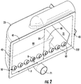
FIG. 2 is a perspective view of nozzles provided in a body of the ECS ofFIG. 1 in accordance with embodiments; -
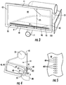
FIG. 3 is a perspective view of a slotted air nozzle provided in a body of the ECS ofFIG. 1 in accordance with embodiments; -
FIG. 4 is a side view of the nozzles ofFIG. 2 in accordance with embodiments; -
FIG. 5 is an elevation view of the nozzles ofFIG. 2 in accordance with embodiments; -
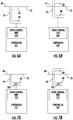
FIG. 6A is a side view of an electro-magnetic or hydraulic control of the nozzles ofFIGS. 2 ,4 and 5 ; -
FIG. 6B is a side view of the electro-magnetic or hydraulic control of the nozzles ofFIGS. 2 ,4 and 5 ; -
FIG. 7A is a side view of a hydraulic or pneumatic control of the nozzles ofFIGS. 2 ,4 and 5 ; -
FIG. 7B is a side view of the hydraulic or pneumatic control of the nozzles ofFIGS. 2 ,4 and 5 ; -
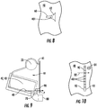
FIG. 8 is a top-down view of a single nozzle in accordance with embodiments; -
FIG. 9 is a side view of the slotted air nozzle ofFIG. 3 in accordance with embodiments; -
FIG. 10 is an elevation view of the slotted air nozzle ofFIG. 3 in accordance with embodiments; -
FIG. 11A is a side view of an electro-magnetic or hydraulic control of the slotted air nozzle ofFIGS. 3 ,9 and 10 ; -
FIG. 11B is a side view of the electro-magnetic or hydraulic control of the slotted air nozzle ofFIGS. 3 ,9 and 10 ; -
FIG. 12A is a side view of a hydraulic or pneumatic control of the slotted air nozzle ofFIGS. 3 ,9 and 10 ; -
FIG. 12B is a side view of the hydraulic or pneumatic control of the slotted air nozzle ofFIGS. 3 ,9 and 10 ; -
FIG. 13 is a top-down view of two slotted air nozzles in accordance with embodiments; and -
FIG. 14 is a flow diagram illustrating a method of operating a RAM air inlet (RIH) in accordance with embodiments. - These and other advantages and features will become more apparent from the following description taken in conjunction with the drawings.
- As will be described below, air exhaust nozzle features are provided to a RAM inlet header (RIH). In some cases, multiple turbine air exhaust nozzles are added to the RIH. These nozzles direct excess pack turbine cooled air towards the RAM heat exchanger cold-cold corner in order to achieve additional system performance during certain operating modes. The nozzle quantities, positions and sizes are optimized to maximize system performance in terms of cooling and water removal. A distance from outlets of the nozzles is provided to allow cooling flows to distribute along the heat exchanger cold-cold corner. The nozzles are configured to avoid obstructing internal header flows and spaces between the nozzles minimize risk of obstructing flows to the cold-cold corner of the heat exchanger. In other cases, a slotted turbine air exhaust nozzle is added to the RIH. The slotted air nozzle directs excess pack turbine cooled air towards the RAM heat exchanger cold-cold corner in order to achieve additional system performance during certain operating modes. The slotted air nozzle provides a curtain of air directed towards the cold-cold corner of the heat exchanger. The slotted air nozzle is positioned and sized to be optimized to maximize system performance in terms of cooling and water removal. The slot height can be varied to enhance flow distribution and a distance from the slotted air nozzle outlet may be provided to distribute cooled air along the heat exchanger cold-cold corner without obstructing internal header flows.
- With reference to
FIG. 1 , an environmental control system (ECS) 10 of an aircraft is provided and includes at least one of first andsecond sources RIH 20. Thefirst source 11 may be provided, for example, as a fresh air turbine and thesecond source 12 may be provided, for example, as a power turbine. In any case, thefirst source 11 is coupled to afirst passageway 110 through which excess cooled air is transported from thefirst source 11 to theRIH 20 and thesecond source 12 is coupled to asecond passageway 120 through which excess cooled air is transported from thesecond source 12 to theRIH 20. - The
RIH 20 includes aninlet 21, anoutlet 22 and abody 23, which is formed to define apassage 230 from theinlet 21 to theoutlet 22. RAM air can be drawn into theinlet 21 during flight operations and is then directed through thebody 23 toward theoutlet 22. Within thebody 23, the RAM air thermally interacts with coolant, which is sprayed into the RAM air by one ormore spray nozzles 231, and first, second andthird heat exchangers - As the RAM air proceeds through the
inlet 21, the RAM air is directed around acorner 232 at which point the RAM air thermally interacts with the coolant. Subsequently, the RAM air thermally interacts with thefirst heat exchanger 31, such as a chiller heat exchanger. Once the RAM air passes through thefirst heat exchanger 31, the RAM air subsequently passes through the second andthird heat exchangers outlet 22. - With reference to
FIGS. 2 and3 , thebody 23 includes afirst body wall 40, asecond body wall 41 disposed at a distance from thefirst body wall 40 andsidewalls sidewalls first body wall 40 and thesecond body wall 41. Thefirst body wall 40, thesecond body wall 41 and thesidewalls first heat exchanger 31. Thecorner 232 is formed from a curvature of thesidewall 42, which curves along a plane P of thefirst body wall 40 about an edge of thesidewall 43. At or proximate to thefirst body wall 40, thecorner 232 may be provided as a cold-cold corner of thefirst heat exchanger 31 as heated air moving through thefirst heat exchanger 31 is cooled by thermal interaction with the RAM air upon reaching thecorner 232 at thefirst body wall 40. In accordance with embodiments, the cold-cold corner of thefirst heat exchanger 31 can extend across a span of thefirst body wall 40. - To an extent that the RAM air may not be sufficiently cool, especially on hot days, the
RIH 20 further includes features by which the excess cooled air can be provided from the first andsecond sources first heat exchanger 31. As shown inFIGS. 2 and3 , the features include anozzle body 50 that is arranged along thefirst body wall 40 and configured to direct a curtain of cooled air into the flows of the RAM air and toward thefirst heat exchanger 31. In an exemplary case, the cooled air can be provided at a temperature of around 70°F or lower and the RAM air can be provided at a temperature of around 90°F or higher and, in such cases, the presence of the cooled air provides for substantially improved cooling capability at least at thefirst heat exchanger 31. - With continued reference to
FIG. 2 and with additional reference toFIGS. 4 and 5 , thenozzle body 50 can be provided as a plurality ofnozzles 60 arranged along thefirst body wall 40 to direct the cooled air into the flows of the RAM air and toward thefirst heat exchanger 31. As shown inFIGS. 2 ,4 and 5 , eachnozzle 60 is displaced from a neighboringnozzle 60 and includes afirst body 61, asecond body 62 and acurved body 63. Thefirst body 61 is formed to define a first flowpath and is extendable in a first direction D1 from thefirst body wall 40. The first direction D1 is transversely oriented relative to the plane P of thefirst body wall 40 and may be perpendicularly oriented relative to the plane P. Thesecond body 62 is formed to define a second flowpath and is extendable in a second direction D2. The second direction D2 may be transversely oriented relative to the first direction D1 and may be substantially parallel with the plane P. Thecurved body 63 forms a smooth, low-profile and aerodynamic surface that minimally inhibits the flows of the RAM air. Thecurved body 63 is fluidly interposed between the first andsecond bodies first body wall 40 is formed to define holes 401 (seeFIG. 5 ) which are respectively communicative with interiors of each of thenozzles 60. - The
RIH 20 further includes a manifold 70 and atubular body 80. The manifold 70 includes a manifold intake 71 (seeFIG. 2 ) and is disposed at an exterior surface of thefirst body wall 40 at an exterior of thebody 23. The manifold 70 is configured to distribute the cooled air to eachnozzle 60 via theholes 401. Thetubular body 80 is configured to transport the cooled air from theintake 71. - Thus, cooled air provided from the first and
second sources second passageways tubular body 80, which in turn transports the cooled air to thenozzles 60 via theholes 401. Within thenozzles 60, the cooled air moves through the first flowpaths and then the second flowpaths and is exhausted into the flows of the RAM air and toward thefirst heat exchanger 31. In accordance with embodiments, the manifold 70 and thenozzles 60 may each be configured such that a predominant flow direction of the cooled air leaving thesecond body 62 of eachnozzle 60 opposes a predominant flow direction of the cooled air in thetubular body 80. - In accordance with embodiments, each of the
nozzles 60 may have a substantially uniform shape and size although it is to be understood that some of thenozzles 60 may be differently configured from others or otherwise unique. For example, in some embodiments, thenozzles 60 in a central region of thebody 23 maybe larger than thenozzles 60 proximate to thesidewalls nozzles 60 are respectively sized and shaped to provide the curtain of the cooled air as a substantially uniform curtain along thefirst body wall 40. - In accordance with embodiments, the plurality of
nozzles 60 may be arranged in a linear formation with substantially uniform spacing between neighboringnozzles 60 along thefirst body wall 40 although it is to be understood that some of thenozzles 60 may be arranged differently. For example, in some embodiments, thenozzles 60 may be concentrated more in a central region of thebody 23 than thenozzles 60 proximate to thesidewalls nozzles 60 are respectively arranged to provide the curtain of the cooled air as a substantially uniform curtain along thefirst body wall 40. - In accordance with embodiments, a height H of each of the
nozzles 60 may be substantially less than a distance DS between thefirst body wall 40 and the second body wall 41 (seeFIG. 2 ). In this way, the curtain of cooled air is provided at or proximate to thefirst body wall 40. However, in accordance with embodiments, the height H of each of thenozzles 60 as measured from thefirst body wall 40 may be variable (the variability of the height H may be provided by electro-magnetic, hydraulic or pneumatic mechanisms as will be described below). Thus, it is possible that the plurality of thenozzles 60 can be configured as a whole to provide the curtain of cooled air with varying characteristics. For example, thenozzles 60 in a central region of thebody 23 can have different heights H as compared to thenozzles 60 proximate to thesidewalls - With reference to
FIGS. 6A and 6B and toFIGS. 7A and 7B , eachnozzle 60 may be independently or dependently extendable or retractable electro-magnetically, hydraulically or pneumatically. - For the electro-magnetic and hydraulic extension and retraction, as shown in
FIGS. 6A and 6B , acontroller 601 may be provided with aservo control unit 602 that is coupled to one or more of thenozzles 60. Thecontroller 601 determines when the cooled air from thesources servo control unit 602 as to when to activate the one or more of thenozzles 60. Upon receiving such instruction, theservo control unit 602 engages to move the one or more of thenozzles 60 from stowed positions (seeFIG. 6A ) at an exterior of thebody 23 to active positions within the body 23 (seeFIG. 6B ). - For the hydraulic and pneumatic extension and retraction, as shown in
FIGS. 7A and 7B , acontroller 701 may be provided with aservo control unit 702 that is coupled to avalve 703 in thetubular body 80. Thecontroller 701 determines when the cooled air from thesources servo control unit 702 as to when to open thevalve 703. Upon receiving such instruction, theservo control unit 702 engages to open thevalve 703 which results in thenozzles 60 inflating from uninflated conditions (seeFIG. 7A ) to inflated conditions (seeFIG. 7B ). - With reference to
FIG. 8 and, in accordance with further embodiments, while thenozzles 60 are illustrated inFIG. 2 andFIGS. 4-7B as being provided as a plurality ofnozzles 60, it is to be understood that thenozzles 60 may be provided as one ormore nozzles 60. For example, as shown inFIG. 8 , asingle nozzle 60 may be provided in a central region of thebody 23. Thissingle nozzle 60 may be configured to provide for the formation of the curtain of cooled air by an outward tapering of at least thesecond body 62. - With reference back to
FIG. 3 and with additional reference toFIGS. 9 and 10 , thenozzle body 50 can be provided as a slottedair nozzle 90 disposed along thefirst body wall 40 to direct the cooled air into the flows of the RAM air and toward thefirst heat exchanger 31. As shown inFIGS. 3 ,9 and 10 , the slottedair nozzle 90 includes afirst nozzle wall 91 and a second nozzle wall 92 (seeFIG. 10 ). Thefirst nozzle wall 91 is extendable in a first direction D1 (seeFIG. 10 ) from thefirst body wall 40. The first direction D1 is transversely oriented relative to the plane P of thefirst body wall 40 and may be perpendicularly oriented relative to the plane P. Thefirst nozzle wall 91 is formed to define a slot 93 (seeFIG. 3 ). Theslot 93 extends above and along the plane P of thefirst body wall 40 along substantially an entire length of the slotted air nozzle 90 (i.e., theslot 93 may be slightly shorter than the first andsecond nozzle walls 91 and 92). Thesecond nozzle wall 92 is displaced, at the plane P of thefirst body wall 40, aft from thefirst nozzle wall 91 relative to a predominant direction of the RAM air flows through thebody 23. Thesecond nozzle wall 92 is curvi-linearly extendable from thefirst body wall 40 toward a distal edge of thefirst nozzle wall 91 so as to form a smooth, low-profile and aerodynamic surface that minimally inhibits the flows of the RAM air. Thefirst body wall 40 is formed to define holes 401 (seeFIG. 10 ) which are respectively communicative with an interior of the slottedair nozzle 90. - As noted above, the
RIH 20 further includes the manifold 70 and thetubular body 80. The manifold 70 includes the manifold intake 71 (seeFIG. 3 ) and is disposed at the exterior surface of thefirst body wall 40 at the exterior of thebody 23. The manifold 70 is configured to distribute the cooled air to the slottedair nozzle 90 via theholes 401. Thetubular body 80 is configured to transport the cooled air to theintake 71. - Thus, the cooled air provided from the first and
second sources second passageways tubular body 80, which in turn transports the cooled air to the slottedair nozzle 90 via theholes 401. Within the slottedair nozzle 90, the cooled air moves between the first andsecond nozzle walls first heat exchanger 31 via theslot 93. In accordance with embodiments, the manifold 70 and the slottedair nozzle 90 may each be configured such that a predominant flow direction of the cooled air flowing through theslot 93 opposes a predominant flow direction of the cooled air in thetubular body 80. - In accordance with embodiments, the slotted
air nozzle 90 may have a substantially uniform linear shape that extends along thefirst body wall 40 although it is to be understood that alternate configurations are possible. For example, in some embodiments, the slottedair nozzle 90 may be curved forwardly or aft from a central region of thebody 23 toward thesidewalls air nozzle 90 is sized and shaped to provide the curtain of the cooled air as a substantially uniform curtain along thefirst body wall 40. - In accordance with embodiments, a height H of the slotted
air nozzle 90 may be substantially less than the distance DS between thefirst body wall 40 and the second body wall 41 (seeFIG. 3 ). In this way, the curtain of cooled air is provided at or proximate to thefirst body wall 40. However, in accordance with embodiments, the height H of the slottedair nozzle 90 may be variable as a whole or along its length (the variability of the height H may be provided by electro-magnetic, hydraulic or pneumatic mechanisms as will be described below). Thus, it is possible that the slottedair nozzle 90 can be configured as a whole to provide the curtain of cooled air with varying characteristics. For example, portion of the slottedair nozzle 90 in the central region of thebody 23 can have a different height H as compared to the portions of the slottedair nozzle 90 proximate to thesidewalls - With reference to
FIGS. 11A and 11B and toFIGS. 12A and 12B , the slottedair nozzle 90 may be extendable or retractable electro-magnetically, hydraulically or pneumatically. - For the electro-magnetic and hydraulic extension and retraction, as shown in
FIGS. 11A and 11B , acontroller 1101 may be provided with aservo control unit 1102 coupled to the slottedair nozzle 90. Thecontroller 1101 determines when the cooled air from thesources servo control unit 1102 as to when to activate the slottedair nozzle 90. Upon receiving such instruction, theservo control unit 1102 engages to move the slottedair nozzle 90 from the stowed position (seeFIG. 11A ) at an exterior of thebody 23 to an active position within the body 23 (seeFIG. 11B ). - For the hydraulic and pneumatic extension and retraction, as shown in
FIGS. 12A and 12B , acontroller 1201 may be provided with aservo control unit 1202 that is coupled to avalve 1203 in thetubular body 80. Thecontroller 1201 determines when the cooled air from thesources servo control unit 1202 as to when to open thevalve 1203. Upon receiving such instruction, theservo control unit 1202 engages to open thevalve 1203 which results in the slottedair nozzle 90 inflating from an uninflated condition (seeFIG. 12A ) to an inflated condition (seeFIG. 12B ). - With reference to
FIG. 13 and, in accordance with further embodiments, while the slottedair nozzle 90 is illustrated inFIG. 3 andFIGS. 8-12B as being provided as a singular element, it is to be understood that one or more slottedair nozzles 90 may be provided. For example, as shown inFIG. 13 , two slottedair nozzles 90 may be provided at opposite sides of thebody 23. The two slottedair nozzles 90 may be respectively configured to cooperatively provide for the formation of the curtain of cooled air by being similarly curved along thefirst body wall 40. - While the various embodiments described herein are generally described separately, it is to be understood that they may be combined in various combinations and permutations. For example, one or more of the
nozzles 60 may be combined with the slottedair nozzle 90 to provide for the formation of the curtain of cooled air. In addition, each of thenozzles 60 and the slottedair nozzle 90 can be formed of metallic, molded or composite (e.g., carbon-fiber) materials. In particular, in the cases of thenozzles 60 and the slottedair nozzle 90 being inflatable as shown inFIGS. 7A and 7B and inFIGS. 12A and 12B , thenozzles 60 and the slottedair nozzle 90 may be formed of elastomeric and/or compliant materials (e.g., rubber). - With reference to
FIG. 14 , a method of operating an RIH as described above is provided and includes determining a temperature of RAM air flows in a body through which RAM air flows from an inlet toward a heat exchanger (1401) and determining a temperature of excess air for use in an environmental control system (ECS) (1402). In an event the temperature of the excess air is less than the temperature of the RAM air flows (1403), the method further includes directing a curtain of the excess air from a nozzle body, which is disposed proximate to a cold-cold corner of the heat exchanger, and along a plane of a wall of the body into flows of the RAM air and toward the heat exchanger (1404). The method may further include electro-magnetically, hydraulically or pneumatically extending the nozzle body in the event the temperature of the excess air is less than the temperature of the RAM air flows and electro-magnetically, hydraulically or pneumatically retracting the nozzle body in the event the temperature of the excess air is greater than the temperature of the RAM air flows. - Technical effects and benefits of the disclosure are the efficient direction of excess turbine cooling air towards the cold-cold corner of the RAM heat exchanger using lightweight elements without obstructing other flows or causing excessive pressure drops.
- While the disclosure is provided in detail in connection with only a limited number of embodiments, it should be readily understood that the disclosure is not limited to such disclosed embodiments. Rather, the disclosure can be modified to incorporate any number of variations, alterations, substitutions or equivalent arrangements not heretofore described, but which are commensurate with the spirit and scope of the disclosure. Additionally, while various embodiments of the disclosure have been described, it is to be understood that the exemplary embodiment(s) may include only some of the described exemplary aspects. Accordingly, the disclosure is not to be seen as limited by the foregoing description, but is only limited by the scope of the appended claims.
Claims (15)
- A RAM inlet header (RIH) (20), comprising:a body (23) through which RAM air flows from an inlet (21) toward a heat exchanger;a nozzle body (50) arranged along a wall of the body to direct a curtain of cooled air into flows of the RAM air and toward the heat exchanger.
- The RIH according to claim 1, wherein the body (23) has a curvature parallel to a plane of the wall.
- The RIH according to claim 1 or 2, wherein the nozzle body (50) is proximate to a cold-cold corner of the heat exchanger.
- The RIH according to claim 1, 2 or 3, wherein the curtain is formed along a plane of the wall.
- The RIH according to any preceding claim, wherein the nozzle body comprises at least one of metallic, molded and composite materials.
- The RIH according to any preceding claim, wherein the nozzle body (50) is electro-magnetically, hydraulically or pneumatically extendable and retractable.
- A RAM inlet header (RIH) (20), comprising:a body (23) through which RAM air flows from an inlet toward a heat exchanger;a plurality of nozzles (60) arranged along a wall (40) of the body (23) to direct cooled air into flows of the RAM air and toward the heat exchanger (31);each nozzle (60) being displaced from a neighboring nozzle and comprising:a first body (61), which is formed to define a first flowpath and which is extendable in a first direction from the wall of the body;a second body (62), which is formed to define a second flowpath and which is extendable in a second direction along a plane of the wall of the body; anda curved body (63) interposed between the first (61) and second bodies (62) and by which the second flowpath is receptive of fluid from the first flowpath.
- The RIH according to claim 7, wherein the body has a curvature parallel to a plane of the wall, the wall is formed to define holes (401) and the RIH further comprises:a manifold (70) disposed at an exterior of the body (23) and configured to distribute the cooled air to each nozzle (60) via the holes (401); anda tubular body (80) to transport the cooled air to an intake of the manifold, and optionally, wherein a predominant flow direction of the cooled air leaving the second body (62) of each nozzle (60) opposes a predominant flow direction of the cooled air in the tubular body (80).
- The RIH according to claim 7 or 8, wherein each of the nozzles (60) has a substantially uniform shape and size, or wherein the plurality of nozzles (60) is arranged in a linear formation with substantially uniform spacing along the wall.
- The RIH according to claim 7, 8 or 9, wherein a height of each of the nozzles (60) is substantially less than a distance between the wall and an opposite wall of the body, or wherein a height of each of the nozzles (60) as measured from the wall is variable.
- The RIH according to claim 7, 8, 9 or 10, wherein each nozzle (60) is electro-magnetically, hydraulically or pneumatically extendable and retractable.
- A RAM inlet header (RIH), comprising:a body (23) through which RAM air flows from an inlet toward a heat exchanger;one or more nozzles (60) arranged along a wall of the body (23) to direct cooled air into flows of the RAM air and toward the heat exchanger;the one or more nozzles (60) being displaced from one or more neighboring nozzles and respectively comprising:a first body (61), which is formed to define a first flowpath and which is extendable in a first direction from the wall of the body;a second body (62), which is formed to define a second flowpath and which is extendable in a second direction along a plane of the wall of the body; anda curved body (63) interposed between the first (61) and second bodies (62) and by which the second flowpath is receptive of fluid from the first flowpath.
- The RIH according to claim 12, wherein the body has a curvature parallel to a plane of the wall, the wall is formed to define one or more holes and the RIH further comprises:a manifold (70) disposed at an exterior of the body (23) and configured to distribute the cooled air to each of the one or more nozzles (60) via the one or more holes (401); anda tubular body (80) to transport the cooled air to an intake of the manifold (70).
- The RIH according to claim 12 or 13, wherein a predominant flow direction of the cooled air leaving the second body (62) of each of the one or more nozzles (60) opposes a predominant flow direction of the cooled air in the tubular body, and/or wherein a height of each of the one or more nozzles (60) is substantially less than a distance between the wall and an opposite wall of the body (23).
- The RIH according to claim 12, 13 or 14, wherein a height of each of the one or more nozzles (60) as measured from the wall is variable, and/or wherein each of the one or more nozzles (60) is electro-magnetically, hydraulically or pneumatically extendable and retractable.
Applications Claiming Priority (1)
| Application Number | Priority Date | Filing Date | Title |
|---|---|---|---|
| US16/014,682 US11130581B2 (en) | 2018-06-21 | 2018-06-21 | Air nozzle arrangement |
Publications (2)
| Publication Number | Publication Date |
|---|---|
| EP3587766A1 true EP3587766A1 (en) | 2020-01-01 |
| EP3587766B1 EP3587766B1 (en) | 2025-04-30 |
Family
ID=66857747
Family Applications (1)
| Application Number | Title | Priority Date | Filing Date |
|---|---|---|---|
| EP19179926.1A Active EP3587766B1 (en) | 2018-06-21 | 2019-06-13 | Ram inlet header |
Country Status (2)
| Country | Link |
|---|---|
| US (1) | US11130581B2 (en) |
| EP (1) | EP3587766B1 (en) |
Families Citing this family (1)
| Publication number | Priority date | Publication date | Assignee | Title |
|---|---|---|---|---|
| US11999490B2 (en) * | 2020-08-28 | 2024-06-04 | The Boeing Company | Air curtain systems and methods for vehicle cabins |
Citations (4)
| Publication number | Priority date | Publication date | Assignee | Title |
|---|---|---|---|---|
| US3752422A (en) * | 1971-06-30 | 1973-08-14 | Boeing Co | Jet augmented ram air scoop |
| EP2868579A1 (en) * | 2013-11-04 | 2015-05-06 | Airbus Operations GmbH | Aircraft air conditioning system and method of operating an aircraft air conditioning system |
| US20150251761A1 (en) * | 2014-03-10 | 2015-09-10 | The Boeing Company | Dry ice draw through galley cooling |
| US20170341757A1 (en) * | 2016-05-24 | 2017-11-30 | Textron Aviation Inc. | Compressor temperature control system and method |
Family Cites Families (12)
| Publication number | Priority date | Publication date | Assignee | Title |
|---|---|---|---|---|
| US2817959A (en) * | 1954-05-03 | 1957-12-31 | Rheem Mfg Co | Heat exchange system |
| GB2244098A (en) | 1990-05-17 | 1991-11-20 | Secr Defence | Variable configuration gas turbine engine |
| US6488219B1 (en) * | 1999-07-21 | 2002-12-03 | D. Scott Herr | Steam humidifier with pressure variable aperture |
| FR2823181B1 (en) * | 2001-04-06 | 2003-08-22 | Dassault Aviat | FRESH AIR SUPPLY DEVICE FOR AN AIRCRAFT |
| US7188488B2 (en) | 2003-03-12 | 2007-03-13 | Hamilton Sundstrand | Pack and a half condensing cycle pack with combined heat exchangers |
| US20110259546A1 (en) * | 2010-04-27 | 2011-10-27 | Hamilton Sundstrand Corporation | Ram flow modulation valve |
| WO2013166077A1 (en) | 2012-04-30 | 2013-11-07 | Curtiss-Wright Flow Control Corporation | Center feed system employing removable inserts in a retractable injection nozzle |
| EP2835312B1 (en) | 2013-08-09 | 2018-01-17 | Hamilton Sundstrand Corporation | Cold corner flow baffle |
| US9656756B2 (en) | 2014-03-10 | 2017-05-23 | The Boeing Company | Turbo-compressor system and method for extracting energy from an aircraft engine |
| US10144517B2 (en) | 2016-05-26 | 2018-12-04 | Hamilton Sundstrand Corporation | Mixing bleed and ram air using a two turbine architecture with an outflow heat exchanger |
| US20180058317A1 (en) | 2016-08-24 | 2018-03-01 | General Electric Company | System and method for reduced turbine degradation by chemical injection |
| US10633098B2 (en) | 2016-10-24 | 2020-04-28 | Hamilton Sundstrand Corporation | Environmental control system |
-
2018
- 2018-06-21 US US16/014,682 patent/US11130581B2/en active Active
-
2019
- 2019-06-13 EP EP19179926.1A patent/EP3587766B1/en active Active
Patent Citations (4)
| Publication number | Priority date | Publication date | Assignee | Title |
|---|---|---|---|---|
| US3752422A (en) * | 1971-06-30 | 1973-08-14 | Boeing Co | Jet augmented ram air scoop |
| EP2868579A1 (en) * | 2013-11-04 | 2015-05-06 | Airbus Operations GmbH | Aircraft air conditioning system and method of operating an aircraft air conditioning system |
| US20150251761A1 (en) * | 2014-03-10 | 2015-09-10 | The Boeing Company | Dry ice draw through galley cooling |
| US20170341757A1 (en) * | 2016-05-24 | 2017-11-30 | Textron Aviation Inc. | Compressor temperature control system and method |
Also Published As
| Publication number | Publication date |
|---|---|
| US11130581B2 (en) | 2021-09-28 |
| US20190389585A1 (en) | 2019-12-26 |
| EP3587766B1 (en) | 2025-04-30 |
Similar Documents
| Publication | Publication Date | Title |
|---|---|---|
| US9469187B1 (en) | Vehicle radiator V type layout | |
| EP3770067B1 (en) | Leading-edge thermal anti-ice systems and methods | |
| US20160332724A1 (en) | Heat exchanger for laminar-flow aircraft | |
| US11203437B2 (en) | Assembly and method for conditioning engine-heated air onboard an aircraft | |
| US9200570B2 (en) | Air-cooled oil cooler for turbofan engine | |
| US20170326950A1 (en) | Vehicle radiator v type layout | |
| US20170030265A1 (en) | Bleed air valve a turbine engine with anti-ice valve assembly and method of operating | |
| CN112298580B (en) | Vehicle Heat Exchanger Systems | |
| CN113090410B (en) | An S-curved nozzle of an adaptive cycle engine with impingement-film cooling structure | |
| US9403600B2 (en) | Integrated thermal protection and leakage reduction in a supersonic air intake system | |
| JP2009503332A (en) | An aircraft propulsion device and an aircraft equipped with at least one such propulsion device | |
| US20180118331A1 (en) | Air distribution system with drag reducing inlet | |
| EP3587976B1 (en) | Air nozzle arrangement | |
| US12498178B2 (en) | Evolutive precooler | |
| EP3587766B1 (en) | Ram inlet header | |
| US20200172252A1 (en) | Cleanout systems for use with aircraft | |
| US11199365B2 (en) | Heat exchanger | |
| CN119018358B (en) | Sweating cooling front edge heat protection structure coupled with reverse steam injection | |
| CN115492684B (en) | A composite anti-icing structure for jet pre-cooling device | |
| CN113602503A (en) | Flute venturi tube, aircraft defroster and aircraft | |
| EP3196441B1 (en) | Methods and systems for cooling a coolant airflow in a gas turbine engine | |
| US9921009B2 (en) | Dual-use ram-primary/regen hx | |
| CN112455695B (en) | Air ducts, air conditioning systems and aircraft | |
| BR102022018671A2 (en) | VEHICLE, ENVIRONMENTAL CONTROL SYSTEM AND METHOD FOR OPERATING AN ENVIRONMENTAL CONTROL SYSTEM | |
| HK1240545A1 (en) | Vehicle radiator v-type layout |
Legal Events
| Date | Code | Title | Description |
|---|---|---|---|
| PUAI | Public reference made under article 153(3) epc to a published international application that has entered the european phase |
Free format text: ORIGINAL CODE: 0009012 |
|
| STAA | Information on the status of an ep patent application or granted ep patent |
Free format text: STATUS: THE APPLICATION HAS BEEN PUBLISHED |
|
| AK | Designated contracting states |
Kind code of ref document: A1 Designated state(s): AL AT BE BG CH CY CZ DE DK EE ES FI FR GB GR HR HU IE IS IT LI LT LU LV MC MK MT NL NO PL PT RO RS SE SI SK SM TR |
|
| AX | Request for extension of the european patent |
Extension state: BA ME |
|
| STAA | Information on the status of an ep patent application or granted ep patent |
Free format text: STATUS: REQUEST FOR EXAMINATION WAS MADE |
|
| 17P | Request for examination filed |
Effective date: 20200629 |
|
| RBV | Designated contracting states (corrected) |
Designated state(s): AL AT BE BG CH CY CZ DE DK EE ES FI FR GB GR HR HU IE IS IT LI LT LU LV MC MK MT NL NO PL PT RO RS SE SI SK SM TR |
|
| STAA | Information on the status of an ep patent application or granted ep patent |
Free format text: STATUS: EXAMINATION IS IN PROGRESS |
|
| 17Q | First examination report despatched |
Effective date: 20201119 |
|
| GRAP | Despatch of communication of intention to grant a patent |
Free format text: ORIGINAL CODE: EPIDOSNIGR1 |
|
| STAA | Information on the status of an ep patent application or granted ep patent |
Free format text: STATUS: GRANT OF PATENT IS INTENDED |
|
| INTG | Intention to grant announced |
Effective date: 20241125 |
|
| GRAS | Grant fee paid |
Free format text: ORIGINAL CODE: EPIDOSNIGR3 |
|
| GRAA | (expected) grant |
Free format text: ORIGINAL CODE: 0009210 |
|
| STAA | Information on the status of an ep patent application or granted ep patent |
Free format text: STATUS: THE PATENT HAS BEEN GRANTED |
|
| AK | Designated contracting states |
Kind code of ref document: B1 Designated state(s): AL AT BE BG CH CY CZ DE DK EE ES FI FR GB GR HR HU IE IS IT LI LT LU LV MC MK MT NL NO PL PT RO RS SE SI SK SM TR |
|
| REG | Reference to a national code |
Ref country code: CH Ref legal event code: EP Ref country code: GB Ref legal event code: FG4D |
|
| REG | Reference to a national code |
Ref country code: IE Ref legal event code: FG4D |
|
| REG | Reference to a national code |
Ref country code: DE Ref legal event code: R096 Ref document number: 602019069245 Country of ref document: DE |
|
| PGFP | Annual fee paid to national office [announced via postgrant information from national office to epo] |
Ref country code: GB Payment date: 20250630 Year of fee payment: 7 |
|
| PGFP | Annual fee paid to national office [announced via postgrant information from national office to epo] |
Ref country code: FR Payment date: 20250630 Year of fee payment: 7 |
|
| REG | Reference to a national code |
Ref country code: NL Ref legal event code: MP Effective date: 20250430 |
|
| REG | Reference to a national code |
Ref country code: AT Ref legal event code: MK05 Ref document number: 1790210 Country of ref document: AT Kind code of ref document: T Effective date: 20250430 |
|
| PG25 | Lapsed in a contracting state [announced via postgrant information from national office to epo] |
Ref country code: FI Free format text: LAPSE BECAUSE OF FAILURE TO SUBMIT A TRANSLATION OF THE DESCRIPTION OR TO PAY THE FEE WITHIN THE PRESCRIBED TIME-LIMIT Effective date: 20250430 Ref country code: ES Free format text: LAPSE BECAUSE OF FAILURE TO SUBMIT A TRANSLATION OF THE DESCRIPTION OR TO PAY THE FEE WITHIN THE PRESCRIBED TIME-LIMIT Effective date: 20250430 Ref country code: PT Free format text: LAPSE BECAUSE OF FAILURE TO SUBMIT A TRANSLATION OF THE DESCRIPTION OR TO PAY THE FEE WITHIN THE PRESCRIBED TIME-LIMIT Effective date: 20250901 |
|
| PGFP | Annual fee paid to national office [announced via postgrant information from national office to epo] |
Ref country code: DE Payment date: 20250724 Year of fee payment: 7 |
|
| REG | Reference to a national code |
Ref country code: LT Ref legal event code: MG9D |
|
| PG25 | Lapsed in a contracting state [announced via postgrant information from national office to epo] |
Ref country code: NO Free format text: LAPSE BECAUSE OF FAILURE TO SUBMIT A TRANSLATION OF THE DESCRIPTION OR TO PAY THE FEE WITHIN THE PRESCRIBED TIME-LIMIT Effective date: 20250730 Ref country code: GR Free format text: LAPSE BECAUSE OF FAILURE TO SUBMIT A TRANSLATION OF THE DESCRIPTION OR TO PAY THE FEE WITHIN THE PRESCRIBED TIME-LIMIT Effective date: 20250731 |
|
| PG25 | Lapsed in a contracting state [announced via postgrant information from national office to epo] |
Ref country code: PL Free format text: LAPSE BECAUSE OF FAILURE TO SUBMIT A TRANSLATION OF THE DESCRIPTION OR TO PAY THE FEE WITHIN THE PRESCRIBED TIME-LIMIT Effective date: 20250430 Ref country code: NL Free format text: LAPSE BECAUSE OF FAILURE TO SUBMIT A TRANSLATION OF THE DESCRIPTION OR TO PAY THE FEE WITHIN THE PRESCRIBED TIME-LIMIT Effective date: 20250430 |
|
| PG25 | Lapsed in a contracting state [announced via postgrant information from national office to epo] |
Ref country code: BG Free format text: LAPSE BECAUSE OF FAILURE TO SUBMIT A TRANSLATION OF THE DESCRIPTION OR TO PAY THE FEE WITHIN THE PRESCRIBED TIME-LIMIT Effective date: 20250430 |
|
| PG25 | Lapsed in a contracting state [announced via postgrant information from national office to epo] |
Ref country code: HR Free format text: LAPSE BECAUSE OF FAILURE TO SUBMIT A TRANSLATION OF THE DESCRIPTION OR TO PAY THE FEE WITHIN THE PRESCRIBED TIME-LIMIT Effective date: 20250430 |
|
| PG25 | Lapsed in a contracting state [announced via postgrant information from national office to epo] |
Ref country code: AT Free format text: LAPSE BECAUSE OF FAILURE TO SUBMIT A TRANSLATION OF THE DESCRIPTION OR TO PAY THE FEE WITHIN THE PRESCRIBED TIME-LIMIT Effective date: 20250430 |
|
| PG25 | Lapsed in a contracting state [announced via postgrant information from national office to epo] |
Ref country code: RS Free format text: LAPSE BECAUSE OF FAILURE TO SUBMIT A TRANSLATION OF THE DESCRIPTION OR TO PAY THE FEE WITHIN THE PRESCRIBED TIME-LIMIT Effective date: 20250731 |
|
| PG25 | Lapsed in a contracting state [announced via postgrant information from national office to epo] |
Ref country code: IS Free format text: LAPSE BECAUSE OF FAILURE TO SUBMIT A TRANSLATION OF THE DESCRIPTION OR TO PAY THE FEE WITHIN THE PRESCRIBED TIME-LIMIT Effective date: 20250830 |
|
| PG25 | Lapsed in a contracting state [announced via postgrant information from national office to epo] |
Ref country code: LV Free format text: LAPSE BECAUSE OF FAILURE TO SUBMIT A TRANSLATION OF THE DESCRIPTION OR TO PAY THE FEE WITHIN THE PRESCRIBED TIME-LIMIT Effective date: 20250430 |
|
| PG25 | Lapsed in a contracting state [announced via postgrant information from national office to epo] |
Ref country code: DK Free format text: LAPSE BECAUSE OF FAILURE TO SUBMIT A TRANSLATION OF THE DESCRIPTION OR TO PAY THE FEE WITHIN THE PRESCRIBED TIME-LIMIT Effective date: 20250430 Ref country code: SM Free format text: LAPSE BECAUSE OF FAILURE TO SUBMIT A TRANSLATION OF THE DESCRIPTION OR TO PAY THE FEE WITHIN THE PRESCRIBED TIME-LIMIT Effective date: 20250430 |
|
| PG25 | Lapsed in a contracting state [announced via postgrant information from national office to epo] |
Ref country code: CZ Free format text: LAPSE BECAUSE OF FAILURE TO SUBMIT A TRANSLATION OF THE DESCRIPTION OR TO PAY THE FEE WITHIN THE PRESCRIBED TIME-LIMIT Effective date: 20250430 |
|
| PG25 | Lapsed in a contracting state [announced via postgrant information from national office to epo] |
Ref country code: EE Free format text: LAPSE BECAUSE OF FAILURE TO SUBMIT A TRANSLATION OF THE DESCRIPTION OR TO PAY THE FEE WITHIN THE PRESCRIBED TIME-LIMIT Effective date: 20250430 |
|
| PG25 | Lapsed in a contracting state [announced via postgrant information from national office to epo] |
Ref country code: RO Free format text: LAPSE BECAUSE OF FAILURE TO SUBMIT A TRANSLATION OF THE DESCRIPTION OR TO PAY THE FEE WITHIN THE PRESCRIBED TIME-LIMIT Effective date: 20250430 Ref country code: SK Free format text: LAPSE BECAUSE OF FAILURE TO SUBMIT A TRANSLATION OF THE DESCRIPTION OR TO PAY THE FEE WITHIN THE PRESCRIBED TIME-LIMIT Effective date: 20250430 |
|
| REG | Reference to a national code |
Ref country code: CH Ref legal event code: H13 Free format text: ST27 STATUS EVENT CODE: U-0-0-H10-H13 (AS PROVIDED BY THE NATIONAL OFFICE) Effective date: 20260127 |
|
| PG25 | Lapsed in a contracting state [announced via postgrant information from national office to epo] |
Ref country code: IT Free format text: LAPSE BECAUSE OF FAILURE TO SUBMIT A TRANSLATION OF THE DESCRIPTION OR TO PAY THE FEE WITHIN THE PRESCRIBED TIME-LIMIT Effective date: 20250430 |
|
| PG25 | Lapsed in a contracting state [announced via postgrant information from national office to epo] |
Ref country code: MC Free format text: LAPSE BECAUSE OF FAILURE TO SUBMIT A TRANSLATION OF THE DESCRIPTION OR TO PAY THE FEE WITHIN THE PRESCRIBED TIME-LIMIT Effective date: 20250430 |
|
| REG | Reference to a national code |
Ref country code: DE Ref legal event code: R097 Ref document number: 602019069245 Country of ref document: DE |
|
| PG25 | Lapsed in a contracting state [announced via postgrant information from national office to epo] |
Ref country code: LU Free format text: LAPSE BECAUSE OF NON-PAYMENT OF DUE FEES Effective date: 20250613 |
|
| REG | Reference to a national code |
Ref country code: BE Ref legal event code: MM Effective date: 20250630 |
|
| PLBE | No opposition filed within time limit |
Free format text: ORIGINAL CODE: 0009261 |
|
| STAA | Information on the status of an ep patent application or granted ep patent |
Free format text: STATUS: NO OPPOSITION FILED WITHIN TIME LIMIT |
|
| REG | Reference to a national code |
Ref country code: CH Ref legal event code: L10 Free format text: ST27 STATUS EVENT CODE: U-0-0-L10-L00 (AS PROVIDED BY THE NATIONAL OFFICE) Effective date: 20260311 |
|
| 26N | No opposition filed |
Effective date: 20260202 |
|
| PG25 | Lapsed in a contracting state [announced via postgrant information from national office to epo] |
Ref country code: IE Free format text: LAPSE BECAUSE OF NON-PAYMENT OF DUE FEES Effective date: 20250613 |
|
| PG25 | Lapsed in a contracting state [announced via postgrant information from national office to epo] |
Ref country code: BE Free format text: LAPSE BECAUSE OF NON-PAYMENT OF DUE FEES Effective date: 20250630 |
|
| PG25 | Lapsed in a contracting state [announced via postgrant information from national office to epo] |
Ref country code: CH Free format text: LAPSE BECAUSE OF NON-PAYMENT OF DUE FEES Effective date: 20250630 |