EP3587747A1 - Abnormality treatment apparatus for rotating machine, and rotating machine system - Google Patents
Abnormality treatment apparatus for rotating machine, and rotating machine system Download PDFInfo
- Publication number
- EP3587747A1 EP3587747A1 EP19181087.8A EP19181087A EP3587747A1 EP 3587747 A1 EP3587747 A1 EP 3587747A1 EP 19181087 A EP19181087 A EP 19181087A EP 3587747 A1 EP3587747 A1 EP 3587747A1
- Authority
- EP
- European Patent Office
- Prior art keywords
- control
- rotating machine
- rotor
- liquid injection
- control unit
- Prior art date
- Legal status (The legal status is an assumption and is not a legal conclusion. Google has not performed a legal analysis and makes no representation as to the accuracy of the status listed.)
- Granted
Links
Images



Classifications
-
- F—MECHANICAL ENGINEERING; LIGHTING; HEATING; WEAPONS; BLASTING
- F01—MACHINES OR ENGINES IN GENERAL; ENGINE PLANTS IN GENERAL; STEAM ENGINES
- F01D—NON-POSITIVE DISPLACEMENT MACHINES OR ENGINES, e.g. STEAM TURBINES
- F01D21/00—Shutting-down of machines or engines, e.g. in emergency; Regulating, controlling, or safety means not otherwise provided for
- F01D21/04—Shutting-down of machines or engines, e.g. in emergency; Regulating, controlling, or safety means not otherwise provided for responsive to undesired position of rotor relative to stator or to breaking-off of a part of the rotor, e.g. indicating such position
- F01D21/06—Shutting-down
-
- G—PHYSICS
- G01—MEASURING; TESTING
- G01H—MEASUREMENT OF MECHANICAL VIBRATIONS OR ULTRASONIC, SONIC OR INFRASONIC WAVES
- G01H17/00—Measuring mechanical vibrations or ultrasonic, sonic or infrasonic waves, not provided for in the other groups of this subclass
-
- G—PHYSICS
- G01—MEASURING; TESTING
- G01M—TESTING STATIC OR DYNAMIC BALANCE OF MACHINES OR STRUCTURES; TESTING OF STRUCTURES OR APPARATUS, NOT OTHERWISE PROVIDED FOR
- G01M13/00—Testing of machine parts
- G01M13/02—Gearings; Transmission mechanisms
- G01M13/025—Test-benches with rotational drive means and loading means; Load or drive simulation
-
- F—MECHANICAL ENGINEERING; LIGHTING; HEATING; WEAPONS; BLASTING
- F02—COMBUSTION ENGINES; HOT-GAS OR COMBUSTION-PRODUCT ENGINE PLANTS
- F02C—GAS-TURBINE PLANTS; AIR INTAKES FOR JET-PROPULSION PLANTS; CONTROLLING FUEL SUPPLY IN AIR-BREATHING JET-PROPULSION PLANTS
- F02C7/00—Features, components parts, details or accessories, not provided for in, or of interest apart form groups F02C1/00 - F02C6/00; Air intakes for jet-propulsion plants
- F02C7/12—Cooling of plants
- F02C7/14—Cooling of plants of fluids in the plant, e.g. lubricant or fuel
- F02C7/141—Cooling of plants of fluids in the plant, e.g. lubricant or fuel of working fluid
- F02C7/143—Cooling of plants of fluids in the plant, e.g. lubricant or fuel of working fluid before or between the compressor stages
- F02C7/1435—Cooling of plants of fluids in the plant, e.g. lubricant or fuel of working fluid before or between the compressor stages by water injection
-
- G—PHYSICS
- G01—MEASURING; TESTING
- G01M—TESTING STATIC OR DYNAMIC BALANCE OF MACHINES OR STRUCTURES; TESTING OF STRUCTURES OR APPARATUS, NOT OTHERWISE PROVIDED FOR
- G01M13/00—Testing of machine parts
-
- G—PHYSICS
- G01—MEASURING; TESTING
- G01N—INVESTIGATING OR ANALYSING MATERIALS BY DETERMINING THEIR CHEMICAL OR PHYSICAL PROPERTIES
- G01N29/00—Investigating or analysing materials by the use of ultrasonic, sonic or infrasonic waves; Visualisation of the interior of objects by transmitting ultrasonic or sonic waves through the object
- G01N29/44—Processing the detected response signal, e.g. electronic circuits specially adapted therefor
- G01N29/4454—Signal recognition, e.g. specific values or portions, signal events, signatures
-
- F—MECHANICAL ENGINEERING; LIGHTING; HEATING; WEAPONS; BLASTING
- F01—MACHINES OR ENGINES IN GENERAL; ENGINE PLANTS IN GENERAL; STEAM ENGINES
- F01D—NON-POSITIVE DISPLACEMENT MACHINES OR ENGINES, e.g. STEAM TURBINES
- F01D11/00—Preventing or minimising internal leakage of working-fluid, e.g. between stages
- F01D11/08—Preventing or minimising internal leakage of working-fluid, e.g. between stages for sealing space between rotor blade tips and stator
- F01D11/14—Adjusting or regulating tip-clearance, i.e. distance between rotor-blade tips and stator casing
- F01D11/20—Actively adjusting tip-clearance
- F01D11/24—Actively adjusting tip-clearance by selectively cooling-heating stator or rotor components
-
- F—MECHANICAL ENGINEERING; LIGHTING; HEATING; WEAPONS; BLASTING
- F01—MACHINES OR ENGINES IN GENERAL; ENGINE PLANTS IN GENERAL; STEAM ENGINES
- F01D—NON-POSITIVE DISPLACEMENT MACHINES OR ENGINES, e.g. STEAM TURBINES
- F01D21/00—Shutting-down of machines or engines, e.g. in emergency; Regulating, controlling, or safety means not otherwise provided for
- F01D21/04—Shutting-down of machines or engines, e.g. in emergency; Regulating, controlling, or safety means not otherwise provided for responsive to undesired position of rotor relative to stator or to breaking-off of a part of the rotor, e.g. indicating such position
- F01D21/08—Restoring position
-
- G—PHYSICS
- G01—MEASURING; TESTING
- G01M—TESTING STATIC OR DYNAMIC BALANCE OF MACHINES OR STRUCTURES; TESTING OF STRUCTURES OR APPARATUS, NOT OTHERWISE PROVIDED FOR
- G01M15/00—Testing of engines
- G01M15/14—Testing gas-turbine engines or jet-propulsion engines
Definitions
- the present invention relates to an abnormality treatment apparatus for a rotating machine, and a rotating machine system.
- an abnormality detecting apparatus for detecting contact of a rotor of a rotating machine is known.
- the abnormality detecting apparatus disclosed in Japanese Unexamined Patent Publication No. 2016-57246 has a sensor which detects an elastic wave generated when the rotor contacts something during its rotation. The sensor detects an elastic wave to specify a contact position of the rotor.
- the abnormality detecting apparatus disclosed in Japanese Unexamined Patent Publication No. 2016-57246 specifies a contact position of a rotor during its rotation
- the abnormality detecting apparatus does not take into consideration treatment to be made when contact of the rotor is detected. It is highly possible to avoid a serious failure if a rotating machine is stopped as soon as abnormality is detected. Meanwhile, if stop of the rotating machine can be prevented by taking a measure of avoiding a failure, it is more preferable, in terms of operation, to continue operation of the rotating machine than to immediately stop the operation when abnormality is detected. This enables improvement of operation efficiency.
- An object of the present invention is to enable a rotating machine to continue operation as much as possible even when rotor contact occurs.
- An abnormality treatment apparatus for a rotating machine includes: a sensor configured to output a signal upon detecting an event caused by contact of a rotor of the rotating machine during rotation of the rotor; and a control unit for executing at least one control of rotation number control of reducing the number of rotations of the rotor step by step, liquid injection control of injecting liquid into a housing chamber of the rotor step by step, and pressure control of lowering a discharge pressure of the rotating machine step by step, based on reception of the signal output from the sensor.
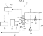
- a rotating machine system 10 is provided with a rotating machine 12, and an abnormality treatment apparatus 14 for the rotating machine 12.
- the rotating machine 12 has a casing 12a in which a rotor 12b, and a housing chamber 12c housing the rotor 12b are provided.
- the rotor 12b is connected to a driving source 21 such as a motor which generates a driving force that causes the rotor 12b to rotate via a speed reducer 23.
- the rotating machine 12 can be any of a compressor, a blower, a pump, a turbine, and the like that pressurize and depressurize gaseous fluid such as air by rotation of the rotor 12b. It is assumed that the rotating machine 12 is configured with a compressor in the present embodiment. Accordingly, the rotating machine 12 sucks air in a suction line 25 through a suction port and compresses the sucked air.
- the air compressed in the housing chamber 12c (compression chamber) in which the rotor 12b is housed is discharged from a discharge port to the discharge line 27.
- the compression chamber present in the housing chamber 12c is a space defined by an inner surface of the housing chamber 12c and the rotor 12b.
- the rotor 12b can be connected to the driving source 21 via a speed increaser, in place of the speed reducer 23.
- a liquid injection line 29 is connected to the rotating machine 12.
- the liquid injection line 29 is a line for sending cooling fluid such as water, organic solvent, or the like into the housing chamber 12c.
- the liquid injection line 29 is connected to the casing 12a so as to communicate with the housing chamber 12c.
- the liquid injection valve 31 may be constantly opened during operation of the rotating machine 12, or may be maintained in a closed state during normal operation and opened only when liquid injection control to be described later is executed.
- the liquid injection line 29 of the present embodiment does not execute liquid injection, and executes the liquid injection to the housing chamber 12c on the basis of an output of a signal indicative of abnormality from a sensor 14a to be described later.
- the liquid injection line 29 may be configured to inject liquid into the housing chamber 12c of the rotor 12b even when the signal indicative of abnormality is not output from the sensor 14a to be described later.
- the discharge line 27 is provided with a pressure detector 33 and a temperature detector 35.
- the discharge line 27 is a line through which fluid discharged from the rotating machine 12 flows.
- the pressure detector 33 detects a pressure of a gaseous fluid such as air, process gas, flare gas, or the like discharged from the rotating machine 12 and outputs a signal indicative of a detection value.
- the temperature detector 35 detects a temperature of a gaseous fluid such as air discharged from the rotating machine 12 and outputs a signal indicative of a detection value.
- a return line 37 is connected to the discharge line 27.
- a front end of the return line 37 is connected to the suction line 25.
- the return valve 39 When the return valve 39 is opened, a part of the gaseous fluid flowing through the discharge line 27 is returned to the suction line 25 through the return line 37.
- a flow rate of the gaseous fluid returned from the discharge line 27 to the suction line 25 is changed according to the opening of the return valve 39. Therefore, the larger the opening of the return valve 39 becomes, the more the gaseous fluid pressure in the discharge line 27 is reduced.
- the abnormality treatment apparatus 14 is provided with the sensor 14a which detects abnormality of the rotor 12b and a control unit 14b which executes prescribed control according to a detection result of the sensor 14a.
- the sensor 14a is attached to the casing 12a of the rotating machine 12.
- the sensor 14a is configured to output a signal indicative of abnormality (hereinafter, referred to as an abnormality signal) upon detecting an event caused by contact of the rotor 12b with the casing 12a (the inner surface of the housing chamber 12c).
- an abnormality signal a signal indicative of abnormality
- the sensor 14a is configured with an AE (Acoustic Emission) sensor, a vibration sensor, or the like to detect ultrasonic waves, vibration, or the like as an event caused by contact.
- the abnormality signal output from the sensor 14a is input to the control unit 14b.
- the sensor 14a continues outputting the abnormality signal while the event is detected.
- the control unit 14b is electrically connected to the sensor 14a, the driving source 21, the liquid injection valve 31, and the return valve 39.
- the control unit 14b is configured to execute notice control such as sounding of alarm (not shown) or lighting of a warning lamp (not shown), as well as executing control (rotation number control) of reducing the number of rotations of the rotor 12b step by step upon receiving the abnormality signal output from the sensor 14a.
- the control unit 14b is also configured to execute control (liquid injection control) of injecting liquid into the housing chamber 12c in a case where the notice control is still continued even after the rotation number control is executed.
- the control unit 14b is also configured to execute control (pressure control) of lowering a discharge pressure of the rotating machine 12 in a case where the notice control is still continued even after the liquid injection control is executed.
- control unit 14b is also configured to stop operation of the rotating machine 12 in a case where the notice control is still continued even after the pressure control is executed.
- FIG. 2 shows a flow of control executed by the control unit 14b when the sensor 14a detects an event caused by contact of the rotor 12b with the casing 12a.
- step ST1 the control unit 14b monitors whether the notice control is executed or not (step ST2).
- step ST2 the processing proceeds to step ST3. While receiving the abnormality signal, the control unit 14b continues executing the notice control.
- step ST3 the control unit 14b executes the rotation number control. This makes the number of rotations of the rotor 12b be lowered to a predetermined lower limit value step by step.
- the control unit 14b checks whether the notice control is still executed or not even during execution of the rotation number control, and even when the number of rotations of the rotor 12b is reduced to the predetermined lower limit value to end the rotation number control, the control unit 14b checks whether the notice control is still executed or not (step ST4).
- the control unit 14b executes the liquid injection control (step ST5).
- Release of the liquid injection valve 31 (or an increase in the opening) is executed to increase the opening step by step while monitoring a discharge temperature of the rotating machine 12.
- the control unit 14b checks whether the notice control is still executed or not during execution of the liquid injection control.
- step ST6 the control unit 14b executes the pressure control (step ST7).
- the control unit 14b checks whether the notice control is still executed during the execution of the pressure control or not. In a case where even after the end of the pressure control, the notice control is executed (YES in step ST8), the control unit 14b stops the operation of the rotating machine 12 (step ST9). On the other hand, when determination is made in steps ST4, ST6, and ST8 that the notice control is ended, the operation of the rotating machine 12 is continued (step ST10).
- the control unit 14b first reduces the number of rotations of the rotor 12b by the number of rotations set in advance (step ST21). Specifically, while the rotating machine 12 operates at a number of rotations set so as to obtain a prescribed discharge flow rate (or discharge pressure), when the notice control is executed (YES in step ST2 in FIG. 2 ), the control unit 14b reduces the number of rotations down to the number of rotations obtained by subtracting a prescribed number of rotations from the set number of rotations.
- the control unit 14b refers to a detected pressure of the pressure detector 33 to determine whether the discharge pressure is stabilized or not (step ST22). Specifically, since the discharge pressure is lowered as a result of reduction of the number of rotations of the rotating machine 12, the control unit 14b determines whether the discharge pressure is stabilized or not depending on whether a pressure change in a prescribed time falls within a prescribed range or not after the discharge pressure is lowered. If the pressure change is within the prescribed range, the control unit 14b determines that the discharge pressure is stable, so that the processing proceeds from step ST22 to step ST23.
- control unit 14b may refer to a detected temperature of the temperature detector 35 to determine whether the discharge temperature is stabilized or not.
- step ST23 the control unit 14b determines whether the notice control is still executed or not.
- operation at the reduced number of rotations is continued (step ST24).
- the processing proceeds from step ST23 to step ST25, so that the control unit 14b checks whether the discharge pressure is lowered to a lower limit value or not (step ST25). If the discharge pressure is not lowered to the lower limit value, the processing returns to step ST21, so that the control unit 14b reduces the number of rotations of the rotor 12b by the number of rotations set in advance. Step-by-step reduction in the number of rotations will be repeated until the discharge pressure reaches the lower limit value set in advance, and when the discharge pressure reaches the lower limit value, the rotation number control ends (step ST26).
- the liquid injection control will be more specifically described with reference to FIG. 4 .
- the notice control is still executed even after the end of the rotation number control (YES in step ST4 in FIG. 2 )
- the liquid injection control is executed.
- the control unit 14b opens the liquid injection valve 31 by an opening set in advance (step ST31). Then, after releasing the liquid injection valve 31 by a prescribed opening, the control unit 14b refers to a detected temperature of the temperature detector 35 to determine whether an discharge temperature is stabilized or not (step ST32). Specifically, since injecting liquid into the housing chamber 12c leads to reduction in the discharge temperature, whether the discharge temperature is stabilized or not is determined depending on whether a temperature change in a prescribed time after the discharge temperature is lowered is within a prescribed range or not. When the temperature change is within the prescribed range, the control unit 14b determines that the discharge temperature is stabilized. The processing thus proceeds from step ST32 to step ST33.
- step ST33 the control unit 14b determines whether the notice control is still executed or not. When the notice control is ended, the operation is continued as it is (step ST34). On the other hand, if the notice control is still executed even after the discharge temperature is stabilized after the liquid injection is executed, the processing proceeds to step ST35, so that the control unit 14b checks whether the liquid injection valve 31 has been opened to the maximum opening or not. If the valve is not fully opened, the processing returns to step ST31, so that the control unit 14b opens the liquid injection valve 31 from the current opening by the opening set in advance. Thus, control is executed of increasing the opening of the liquid injection valve 31 step by step while monitoring the discharge temperature until the opening of the liquid injection valve 31 reaches the maximum opening, and when the liquid injection valve 31 is fully opened, the liquid injection control is ended (step ST36).
- the control unit 14b first opens the return valve 39 by the opening set in advance (step ST41). Then, after opening the return valve 39 by prescribed opening, the control unit 14b refers to a detected pressure of the pressure detector 33 to determine whether the discharge pressure is stabilized or not (step ST42). In other words, since the discharge pressure is lowered by opening the return valve 39, whether the discharge pressure is stabilized or not is determined depending on whether the pressure change in a prescribed time after the reduction of the discharge pressure is within a prescribed range or not. If the pressure change of the discharge pressure is within the prescribed range, the control unit 14b determines that the discharge pressure is stabilized, so that the processing proceeds from step ST42 to step ST43.
- step ST43 the control unit 14b determines whether the notice control is still executed or not. When the notice control is ended, the operation is continued as it is (step ST44). On the other hand, if the notice control is still executed even after the discharge pressure is stabilized after the opening of the return valve 39 is increased, the processing proceeds to step ST45.
- the control unit 14b thus checks whether the return valve 39 is opened to the maximum opening or not (step ST45). If the return valve 39 is not fully opened, the processing returns to step ST41, so that the control unit 14b opens the return valve 39 from the current opening by the opening set in advance. In this manner, control is executed of increasing the opening of the return valve 39 step by step while monitoring the discharge pressure until the opening of the return valve 39 reaches the maximum opening. When the return valve 39 is fully opened, the pressure control is ended (step ST46).
- the control unit 14b executes the rotation number control. Since when the rotation number control is executed, the number of rotations of the rotor 12b is reduced, contact of the rotor 12b might be eliminated. Even if a contact state is continued even after the rotation number control, step-by-step reduction in the number of rotations of the rotor 12b can bring about a state where the contact of the rotor 12b is eliminated or a state of little contact.
- the number of rotations of the rotor 12b is reduced step by step, a harmful effect caused by the reduction in the number of rotations from an optimum state can be suppressed. Accordingly, operation can be continued while preventing the rotating machine 12 from developing a failure. Additionally, since when the liquid injection control is executed after the rotation number control, liquid is introduced into the housing chamber 12c, the temperature of the rotor 12b is lowered. In this manner, contact of the rotor 12b might be eliminated. Also in a case where the liquid injection control is executed, even if the contact state is continued, step by step liquid injection can bring about the state where the contact of the rotor 12b is eliminated or the state of little contact.
- control unit 14b is configured to execute the liquid injection control after the rotation number control. Since the liquid injection control is executed only when, even if the rotation number control is executed, the contact is not eliminated or the degree of the contact is not reduced, it is possible to eliminate the contact while maintaining the state where the temperature in the housing chamber 12c is not lowered from an optimum state as much as possible.
- control unit 14b is configured to execute the pressure control also after the execution of the rotation number control and the liquid injection control. Therefore, even in a case where the contact is not eliminated or in a case where the contact is not reduced even by the rotation number control and the liquid injection control, the pressure control might eliminate such a state, and execution of this control is therefore effective in such a case. Specifically, execution of the plurality of controls when contact occurs, even if no cause of contact is found, might eliminate the contact of the rotor 12b and is therefore effective in such a case.
- the control unit 14b waits for the discharge pressure or the discharge temperature to be stabilized. Even when the discharge pressure or the discharge temperature is stabilized, if the abnormality signal is output from the sensor 14a, the control unit 14b again reduces the number of rotations of the rotor 12b. Accordingly, it is possible to more precisely determine an effect obtained by the reduction in the number of rotations of the rotor 12b and is also possible to reduce the number of rotations by a necessary number.
- the control unit 14b after injecting liquid, the control unit 14b waits for the discharge temperature to be stabilized in the liquid injection control. Even when the discharge temperature is stabilized, if the abnormality signal is output from the sensor 14a, the control unit 14b again injects liquid. Accordingly, it is possible to more precisely determine an effect obtained by injecting the liquid and also possible to suppress excessive liquid injection because only a necessary amount of liquid can be injected.
- the control unit 14b waits for the discharge pressure or the discharge temperature to be stabilized in the pressure control. Even when the discharge pressure or the discharge temperature is stabilized, if the abnormality signal is output from the sensor 14a, the control unit 14b again lowers the discharge pressure. Accordingly, it is possible to more precisely determine an effect obtained by lowering the discharge pressure and also possible to lower the discharge pressure by a necessary amount.
- the control unit 14b executes the liquid injection control.
- the control unit 14b may be instead configured to simultaneously execute the rotation number control and the liquid injection control as shown in FIG. 6 .
- the control unit 14b simultaneously executes the rotation number control and the liquid injection control (step ST52).
- control unit 14b specifically reduces the number of rotations of the rotating machine 12 by a prescribed number of rotations and also opens the liquid injection valve 31 by a prescribed opening as shown in FIG. 7 (step ST61). Then, after checking whether the discharge temperature or the discharge pressure is stabilized after the discharge temperature is lowered or not (step ST62), the control unit 14b checks whether the notice control is continued or not (step ST63). If the notice control is ended, the operation is continued (step ST64). On the other hand, if the notice control is not ended, the control unit 14b checks whether the liquid injection valve 31 is fully opened or not and also checks whether the discharge pressure reaches a lower limit value set in advance or not (step ST65). If none of the conditions is satisfied, the processing returns to step ST61 and when any of the conditions is satisfied, the rotation number control and the liquid injection control are ended (step ST66).
- the control unit 14b checks whether the notice control continues or not (step ST53) as shown in FIG. 6 , and if the notice control is ended, the operation is continued as it is (step ST54). On the other hand, if the notice control is not ended, the control unit 14b executes the pressure control (step ST55). Then, when the notice control is still continued even after the pressure control ends (YES in step ST56), the control unit 14b stops the operation of the rotating machine 12 (step ST57).
- control unit 14b simultaneously executes the rotation number control and the liquid injection control. In other words, even if a cause of the contact of the rotor 12b is not found, a plurality of approaches is made to prevent the contact from occurring. Therefore, it is possible to quickly shift to a state where no contact will occur or a state of less contact.
- the present invention is not limited thereto, but at least one control of the rotation number control, the liquid injection control, and the pressure control may be executed.
- the control unit 14b may be configured to execute only the rotation number control, or only the pressure control.
- the control unit 14b may be configured to execute the liquid injection control or the rotation number control after the execution of the pressure control.
- control unit 14b is configured to execute the notice control
- the present invention is not limited thereto, but the notice control may be omitted.
- the control unit 14b may execute at least one of the rotation number control, the liquid injection control, and the pressure control without executing control for notifying a worker.
- the liquid injection line injects liquid into the housing chamber of the rotating machine irrespective of output of the signal from the sensor. This enables contact during the rotation of the rotor to hardly occur. Then, an amount of liquid injection is increased when the liquid injection control is executed in response to output of a signal which is output when an event caused by contact is detected, such as when contact of the rotor with the housing chamber or the like is detected. It is therefore possible to bring about a state where the contact of the rotor is avoided or a state of little contact.
- An abnormality treatment apparatus includes: a sensor which outputs a signal upon detecting an event caused by contact of a rotor of a rotating machine during rotation of the rotor; and a control unit which executes at least one of rotation number control of reducing the number of rotations of the rotor step by step, liquid injection control of injecting liquid into a housing chamber of the rotor step by step, and pressure control of lowering a discharge pressure of the rotating machine step by step based on reception of the signal output from the sensor.
Landscapes
- Engineering & Computer Science (AREA)
- General Physics & Mathematics (AREA)
- Physics & Mathematics (AREA)
- Chemical & Material Sciences (AREA)
- Combustion & Propulsion (AREA)
- General Engineering & Computer Science (AREA)
- Mechanical Engineering (AREA)
- Health & Medical Sciences (AREA)
- Biochemistry (AREA)
- General Health & Medical Sciences (AREA)
- Immunology (AREA)
- Pathology (AREA)
- Analytical Chemistry (AREA)
- Life Sciences & Earth Sciences (AREA)
- Signal Processing (AREA)
- Control Of Positive-Displacement Pumps (AREA)
- Testing Of Devices, Machine Parts, Or Other Structures Thereof (AREA)
- Injection Moulding Of Plastics Or The Like (AREA)
Abstract
Description
- The present invention relates to an abnormality treatment apparatus for a rotating machine, and a rotating machine system.
- As disclosed in Japanese Unexamined Patent Publication No.
2016-57246 2016-57246 - While the abnormality detecting apparatus disclosed in Japanese Unexamined Patent Publication No.
2016-57246 - An object of the present invention is to enable a rotating machine to continue operation as much as possible even when rotor contact occurs.
- An abnormality treatment apparatus for a rotating machine according to one aspect of the present invention includes: a sensor configured to output a signal upon detecting an event caused by contact of a rotor of the rotating machine during rotation of the rotor; and a control unit for executing at least one control of rotation number control of reducing the number of rotations of the rotor step by step, liquid injection control of injecting liquid into a housing chamber of the rotor step by step, and pressure control of lowering a discharge pressure of the rotating machine step by step, based on reception of the signal output from the sensor.
-
-
FIG. 1 is a diagram showing a schematic configuration of a rotating machine system according to an embodiment; -
FIG. 2 is a flow chart showing a flow of an abnormality treatment method executed by an abnormality treatment apparatus of the rotating machine system; -
FIG. 3 is a flow chart showing a flow of rotation number control in the abnormality treatment method; -
FIG. 4 is a flow chart showing a flow of liquid injection control in the abnormality treatment method; -
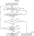
FIG. 5 is a flow chart showing a flow of pressure control in the abnormality treatment method; -
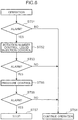
FIG. 6 is a flow chart showing a flow of an abnormality treatment method executed by an abnormality treatment apparatus of a rotating machine system according to another embodiment; and -
FIG. 7 is a flow chart showing a flow of rotation number control and liquid injection control in the abnormality treatment method inFIG. 6 . - In the following, embodiments will be described in detail with reference to the drawings.
- As shown in
FIG. 1 , arotating machine system 10 according to the present embodiment is provided with arotating machine 12, and anabnormality treatment apparatus 14 for therotating machine 12. Therotating machine 12 has acasing 12a in which arotor 12b, and ahousing chamber 12c housing therotor 12b are provided. Therotor 12b is connected to adriving source 21 such as a motor which generates a driving force that causes therotor 12b to rotate via aspeed reducer 23. - The
rotating machine 12 can be any of a compressor, a blower, a pump, a turbine, and the like that pressurize and depressurize gaseous fluid such as air by rotation of therotor 12b. It is assumed that therotating machine 12 is configured with a compressor in the present embodiment. Accordingly, therotating machine 12 sucks air in asuction line 25 through a suction port and compresses the sucked air. The air compressed in thehousing chamber 12c (compression chamber) in which therotor 12b is housed is discharged from a discharge port to thedischarge line 27. The compression chamber present in thehousing chamber 12c is a space defined by an inner surface of thehousing chamber 12c and therotor 12b. Therotor 12b can be connected to thedriving source 21 via a speed increaser, in place of thespeed reducer 23. - A
liquid injection line 29 is connected to therotating machine 12. Theliquid injection line 29 is a line for sending cooling fluid such as water, organic solvent, or the like into thehousing chamber 12c. Theliquid injection line 29 is connected to thecasing 12a so as to communicate with thehousing chamber 12c. There is arranged in the liquid injection line 29 aliquid injection valve 31 formed with an electric valve having an adjustable opening. When theliquid injection valve 31 is opened, cooling fluid flows through theliquid injection line 29 at a flow rate according to the opening of theliquid injection valve 31 and is supplied into thehousing chamber 12c. Theliquid injection valve 31 may be constantly opened during operation of the rotatingmachine 12, or may be maintained in a closed state during normal operation and opened only when liquid injection control to be described later is executed. Specifically, in a normal state where no abnormality is detected, theliquid injection line 29 of the present embodiment does not execute liquid injection, and executes the liquid injection to thehousing chamber 12c on the basis of an output of a signal indicative of abnormality from asensor 14a to be described later. However, this is not always the case. Theliquid injection line 29 may be configured to inject liquid into thehousing chamber 12c of therotor 12b even when the signal indicative of abnormality is not output from thesensor 14a to be described later. - The
discharge line 27 is provided with apressure detector 33 and atemperature detector 35. Thedischarge line 27 is a line through which fluid discharged from therotating machine 12 flows. Thepressure detector 33 detects a pressure of a gaseous fluid such as air, process gas, flare gas, or the like discharged from therotating machine 12 and outputs a signal indicative of a detection value. Thetemperature detector 35 detects a temperature of a gaseous fluid such as air discharged from therotating machine 12 and outputs a signal indicative of a detection value. - A
return line 37 is connected to thedischarge line 27. A front end of thereturn line 37 is connected to thesuction line 25. There is arranged in the return line 37 areturn valve 39 formed with an electric valve having an adjustable opening. When thereturn valve 39 is opened, a part of the gaseous fluid flowing through thedischarge line 27 is returned to thesuction line 25 through thereturn line 37. A flow rate of the gaseous fluid returned from thedischarge line 27 to thesuction line 25 is changed according to the opening of thereturn valve 39. Therefore, the larger the opening of thereturn valve 39 becomes, the more the gaseous fluid pressure in thedischarge line 27 is reduced. - The
abnormality treatment apparatus 14 is provided with thesensor 14a which detects abnormality of therotor 12b and acontrol unit 14b which executes prescribed control according to a detection result of thesensor 14a. - The
sensor 14a is attached to thecasing 12a of therotating machine 12. Thesensor 14a is configured to output a signal indicative of abnormality (hereinafter, referred to as an abnormality signal) upon detecting an event caused by contact of therotor 12b with thecasing 12a (the inner surface of thehousing chamber 12c). Specifically, when therotor 12b contacts thecasing 12a during rotation of therotor 12b, for example, ultrasonic waves, vibration, and the like are generated. Accordingly, thesensor 14a is configured with an AE (Acoustic Emission) sensor, a vibration sensor, or the like to detect ultrasonic waves, vibration, or the like as an event caused by contact. The abnormality signal output from thesensor 14a is input to thecontrol unit 14b. Thesensor 14a continues outputting the abnormality signal while the event is detected. - The
control unit 14b is electrically connected to thesensor 14a, thedriving source 21, theliquid injection valve 31, and thereturn valve 39. Thecontrol unit 14b is configured to execute notice control such as sounding of alarm (not shown) or lighting of a warning lamp (not shown), as well as executing control (rotation number control) of reducing the number of rotations of therotor 12b step by step upon receiving the abnormality signal output from thesensor 14a. Thecontrol unit 14b is also configured to execute control (liquid injection control) of injecting liquid into thehousing chamber 12c in a case where the notice control is still continued even after the rotation number control is executed. Thecontrol unit 14b is also configured to execute control (pressure control) of lowering a discharge pressure of the rotatingmachine 12 in a case where the notice control is still continued even after the liquid injection control is executed. Thecontrol unit 14b is also configured to stop operation of therotating machine 12 in a case where the notice control is still continued even after the pressure control is executed. - Here, description will be made of an abnormality treatment method executed by the
control unit 14b with reference toFIG. 2. FIG. 2 shows a flow of control executed by thecontrol unit 14b when thesensor 14a detects an event caused by contact of therotor 12b with thecasing 12a. - First, during operation of the rotating
machine 12, i.e., when therotor 12b rotates upon receiving a driving force of the driving source 21 (step ST1), thecontrol unit 14b monitors whether the notice control is executed or not (step ST2). When thecontrol unit 14b receives the abnormality signal from thesensor 14a to execute the notice control, the processing proceeds to step ST3. While receiving the abnormality signal, thecontrol unit 14b continues executing the notice control. - In step ST3, the
control unit 14b executes the rotation number control. This makes the number of rotations of therotor 12b be lowered to a predetermined lower limit value step by step. Thecontrol unit 14b checks whether the notice control is still executed or not even during execution of the rotation number control, and even when the number of rotations of therotor 12b is reduced to the predetermined lower limit value to end the rotation number control, thecontrol unit 14b checks whether the notice control is still executed or not (step ST4). - In a case where even after the rotation number control is executed, the notice control is still executed (YES in step ST4), the
control unit 14b executes the liquid injection control (step ST5). This makes theliquid injection valve 31 be opened (or theliquid injection valve 31 is controlled such that the opening of theliquid injection valve 31 becomes larger than in a normal state where no abnormality is detected). Release of the liquid injection valve 31 (or an increase in the opening) is executed to increase the opening step by step while monitoring a discharge temperature of the rotatingmachine 12. As a result of releasing of theliquid injection valve 31 to a maximum opening, when the discharge temperature is lowered to a predetermined lower limit value, the liquid injection control ends. Thecontrol unit 14b checks whether the notice control is still executed or not during execution of the liquid injection control. - In a case where even when the liquid injection control is ended, the notice control is still executed (YES in step ST6), the
control unit 14b executes the pressure control (step ST7). This makes thereturn valve 39 be opened by a prescribed opening. Release of thereturn valve 39 is executed such that the opening of the return valve is increased step by step while monitoring the discharge pressure of the rotatingmachine 12. When thereturn valve 39 is fully opened, the pressure control ends. Thecontrol unit 14b checks whether the notice control is still executed during the execution of the pressure control or not. In a case where even after the end of the pressure control, the notice control is executed (YES in step ST8), thecontrol unit 14b stops the operation of the rotating machine 12 (step ST9). On the other hand, when determination is made in steps ST4, ST6, and ST8 that the notice control is ended, the operation of the rotatingmachine 12 is continued (step ST10). - Next, the rotation number control will be more specifically described with reference to
FIG. 3 . In the rotation number control, thecontrol unit 14b first reduces the number of rotations of therotor 12b by the number of rotations set in advance (step ST21). Specifically, while the rotatingmachine 12 operates at a number of rotations set so as to obtain a prescribed discharge flow rate (or discharge pressure), when the notice control is executed (YES in step ST2 inFIG. 2 ), thecontrol unit 14b reduces the number of rotations down to the number of rotations obtained by subtracting a prescribed number of rotations from the set number of rotations. - Then, after the number of rotations is reduced, the
control unit 14b refers to a detected pressure of thepressure detector 33 to determine whether the discharge pressure is stabilized or not (step ST22). Specifically, since the discharge pressure is lowered as a result of reduction of the number of rotations of the rotatingmachine 12, thecontrol unit 14b determines whether the discharge pressure is stabilized or not depending on whether a pressure change in a prescribed time falls within a prescribed range or not after the discharge pressure is lowered. If the pressure change is within the prescribed range, thecontrol unit 14b determines that the discharge pressure is stable, so that the processing proceeds from step ST22 to step ST23. - Instead of determining whether the discharge pressure is stabilized or not in step ST22, the
control unit 14b may refer to a detected temperature of thetemperature detector 35 to determine whether the discharge temperature is stabilized or not. - In step ST23, the
control unit 14b determines whether the notice control is still executed or not. When the notice control is ended, operation at the reduced number of rotations is continued (step ST24). By contrast, if the notice control is still executed even after the discharge pressure is stabilized after the number of rotations is reduced, the processing proceeds from step ST23 to step ST25, so that thecontrol unit 14b checks whether the discharge pressure is lowered to a lower limit value or not (step ST25). If the discharge pressure is not lowered to the lower limit value, the processing returns to step ST21, so that thecontrol unit 14b reduces the number of rotations of therotor 12b by the number of rotations set in advance. Step-by-step reduction in the number of rotations will be repeated until the discharge pressure reaches the lower limit value set in advance, and when the discharge pressure reaches the lower limit value, the rotation number control ends (step ST26). - Next, the liquid injection control will be more specifically described with reference to
FIG. 4 . In a case where the notice control is still executed even after the end of the rotation number control (YES in step ST4 inFIG. 2 ), the liquid injection control is executed. - In the liquid injection control, first, the
control unit 14b opens theliquid injection valve 31 by an opening set in advance (step ST31). Then, after releasing theliquid injection valve 31 by a prescribed opening, thecontrol unit 14b refers to a detected temperature of thetemperature detector 35 to determine whether an discharge temperature is stabilized or not (step ST32). Specifically, since injecting liquid into thehousing chamber 12c leads to reduction in the discharge temperature, whether the discharge temperature is stabilized or not is determined depending on whether a temperature change in a prescribed time after the discharge temperature is lowered is within a prescribed range or not. When the temperature change is within the prescribed range, thecontrol unit 14b determines that the discharge temperature is stabilized. The processing thus proceeds from step ST32 to step ST33. - In step ST33, the
control unit 14b determines whether the notice control is still executed or not. When the notice control is ended, the operation is continued as it is (step ST34). On the other hand, if the notice control is still executed even after the discharge temperature is stabilized after the liquid injection is executed, the processing proceeds to step ST35, so that thecontrol unit 14b checks whether theliquid injection valve 31 has been opened to the maximum opening or not. If the valve is not fully opened, the processing returns to step ST31, so that thecontrol unit 14b opens theliquid injection valve 31 from the current opening by the opening set in advance. Thus, control is executed of increasing the opening of theliquid injection valve 31 step by step while monitoring the discharge temperature until the opening of theliquid injection valve 31 reaches the maximum opening, and when theliquid injection valve 31 is fully opened, the liquid injection control is ended (step ST36). - Next, the pressure control will be more specifically described with reference to
FIG. 5 . In a case where the notice control is still executed even after the end of the liquid injection control (YES in step ST6 inFIG. 2 ), the pressure control is executed. - In the pressure control, the
control unit 14b first opens thereturn valve 39 by the opening set in advance (step ST41). Then, after opening thereturn valve 39 by prescribed opening, thecontrol unit 14b refers to a detected pressure of thepressure detector 33 to determine whether the discharge pressure is stabilized or not (step ST42). In other words, since the discharge pressure is lowered by opening thereturn valve 39, whether the discharge pressure is stabilized or not is determined depending on whether the pressure change in a prescribed time after the reduction of the discharge pressure is within a prescribed range or not. If the pressure change of the discharge pressure is within the prescribed range, thecontrol unit 14b determines that the discharge pressure is stabilized, so that the processing proceeds from step ST42 to step ST43. - In step ST43, the
control unit 14b determines whether the notice control is still executed or not. When the notice control is ended, the operation is continued as it is (step ST44). On the other hand, if the notice control is still executed even after the discharge pressure is stabilized after the opening of thereturn valve 39 is increased, the processing proceeds to step ST45. Thecontrol unit 14b thus checks whether thereturn valve 39 is opened to the maximum opening or not (step ST45). If thereturn valve 39 is not fully opened, the processing returns to step ST41, so that thecontrol unit 14b opens thereturn valve 39 from the current opening by the opening set in advance. In this manner, control is executed of increasing the opening of thereturn valve 39 step by step while monitoring the discharge pressure until the opening of thereturn valve 39 reaches the maximum opening. When thereturn valve 39 is fully opened, the pressure control is ended (step ST46). - As described in the foregoing, in the present embodiment, upon detecting an event caused by contact of the
rotor 12b, thesensor 14a outputs an abnormality signal. Upon receiving the abnormality signal, thecontrol unit 14b executes the rotation number control. Since when the rotation number control is executed, the number of rotations of therotor 12b is reduced, contact of therotor 12b might be eliminated. Even if a contact state is continued even after the rotation number control, step-by-step reduction in the number of rotations of therotor 12b can bring about a state where the contact of therotor 12b is eliminated or a state of little contact. Additionally, since the number of rotations of therotor 12b is reduced step by step, a harmful effect caused by the reduction in the number of rotations from an optimum state can be suppressed. Accordingly, operation can be continued while preventing the rotatingmachine 12 from developing a failure. Additionally, since when the liquid injection control is executed after the rotation number control, liquid is introduced into thehousing chamber 12c, the temperature of therotor 12b is lowered. In this manner, contact of therotor 12b might be eliminated. Also in a case where the liquid injection control is executed, even if the contact state is continued, step by step liquid injection can bring about the state where the contact of therotor 12b is eliminated or the state of little contact. Additionally, since the liquid is injected step by step, a harmful effect caused by lowering of the temperature in thehousing chamber 12c from an optimum state can be suppressed. Accordingly, operation can be continued while preventing the rotatingmachine 12 from developing a failure. Additionally, since when the pressure control is executed after the liquid injection control, the ejection temperature is lowered, contact of therotor 12b might be eliminated due to heat contraction of therotor 12b. In a case where when the pressure control is executed, even if the contact state continues, lowering the discharge pressure step by step can bring about the state where the contact of therotor 12b is eliminated or the state of little contact. Additionally, since the discharge pressure is lowered step by step, a harmful effect caused by lowering of the discharge pressure from an optimum state can be suppressed. Accordingly, operation can be continued while preventing the rotatingmachine 12 from developing a failure. - Also in the present embodiment, the
control unit 14b is configured to execute the liquid injection control after the rotation number control. Since the liquid injection control is executed only when, even if the rotation number control is executed, the contact is not eliminated or the degree of the contact is not reduced, it is possible to eliminate the contact while maintaining the state where the temperature in thehousing chamber 12c is not lowered from an optimum state as much as possible. - Also in the present embodiment, the
control unit 14b is configured to execute the pressure control also after the execution of the rotation number control and the liquid injection control. Therefore, even in a case where the contact is not eliminated or in a case where the contact is not reduced even by the rotation number control and the liquid injection control, the pressure control might eliminate such a state, and execution of this control is therefore effective in such a case. Specifically, execution of the plurality of controls when contact occurs, even if no cause of contact is found, might eliminate the contact of therotor 12b and is therefore effective in such a case. - Also in the present embodiment, after the number of rotations of the
rotor 12b is reduced by a prescribed number of rotations in the rotation number control, thecontrol unit 14b waits for the discharge pressure or the discharge temperature to be stabilized. Even when the discharge pressure or the discharge temperature is stabilized, if the abnormality signal is output from thesensor 14a, thecontrol unit 14b again reduces the number of rotations of therotor 12b. Accordingly, it is possible to more precisely determine an effect obtained by the reduction in the number of rotations of therotor 12b and is also possible to reduce the number of rotations by a necessary number. - In the present embodiment, after injecting liquid, the
control unit 14b waits for the discharge temperature to be stabilized in the liquid injection control. Even when the discharge temperature is stabilized, if the abnormality signal is output from thesensor 14a, thecontrol unit 14b again injects liquid. Accordingly, it is possible to more precisely determine an effect obtained by injecting the liquid and also possible to suppress excessive liquid injection because only a necessary amount of liquid can be injected. - In the present embodiment, after reducing the discharge pressure, the
control unit 14b waits for the discharge pressure or the discharge temperature to be stabilized in the pressure control. Even when the discharge pressure or the discharge temperature is stabilized, if the abnormality signal is output from thesensor 14a, thecontrol unit 14b again lowers the discharge pressure. Accordingly, it is possible to more precisely determine an effect obtained by lowering the discharge pressure and also possible to lower the discharge pressure by a necessary amount. - The present invention is not limited to the above embodiment but allows for various modifications, improvement, and the like without departing from the gist of the present invention. In the embodiment, in a case where the notice control is still continued even after the rotation number control is ended, the
control unit 14b executes the liquid injection control. Thecontrol unit 14b may be instead configured to simultaneously execute the rotation number control and the liquid injection control as shown inFIG. 6 . In this case, when the notice control is executed during the operation of the rotating machine 12 (YES in step ST51), thecontrol unit 14b simultaneously executes the rotation number control and the liquid injection control (step ST52). - In this control, first, the
control unit 14b specifically reduces the number of rotations of the rotatingmachine 12 by a prescribed number of rotations and also opens theliquid injection valve 31 by a prescribed opening as shown inFIG. 7 (step ST61). Then, after checking whether the discharge temperature or the discharge pressure is stabilized after the discharge temperature is lowered or not (step ST62), thecontrol unit 14b checks whether the notice control is continued or not (step ST63). If the notice control is ended, the operation is continued (step ST64). On the other hand, if the notice control is not ended, thecontrol unit 14b checks whether theliquid injection valve 31 is fully opened or not and also checks whether the discharge pressure reaches a lower limit value set in advance or not (step ST65). If none of the conditions is satisfied, the processing returns to step ST61 and when any of the conditions is satisfied, the rotation number control and the liquid injection control are ended (step ST66). - When the rotation number control and the liquid injection control end, the
control unit 14b checks whether the notice control continues or not (step ST53) as shown inFIG. 6 , and if the notice control is ended, the operation is continued as it is (step ST54). On the other hand, if the notice control is not ended, thecontrol unit 14b executes the pressure control (step ST55). Then, when the notice control is still continued even after the pressure control ends (YES in step ST56), thecontrol unit 14b stops the operation of the rotating machine 12 (step ST57). - In this mode, the
control unit 14b simultaneously executes the rotation number control and the liquid injection control. In other words, even if a cause of the contact of therotor 12b is not found, a plurality of approaches is made to prevent the contact from occurring. Therefore, it is possible to quickly shift to a state where no contact will occur or a state of less contact. - While in the embodiment, the liquid injection control and the pressure control are executed after the execution of the rotation number control, the present invention is not limited thereto, but at least one control of the rotation number control, the liquid injection control, and the pressure control may be executed. For example, the
control unit 14b may be configured to execute only the rotation number control, or only the pressure control. Additionally, thecontrol unit 14b may be configured to execute the liquid injection control or the rotation number control after the execution of the pressure control. - While in the embodiment, the
control unit 14b is configured to execute the notice control, the present invention is not limited thereto, but the notice control may be omitted. Specifically, upon receiving the abnormality signal from thesensor 14a, thecontrol unit 14b may execute at least one of the rotation number control, the liquid injection control, and the pressure control without executing control for notifying a worker. - Here, the embodiments will be outlined.
- (1) The abnormality treatment apparatus for a rotating machine according to the above embodiment is provided with a sensor configured to output a signal upon detecting an event caused by contact of a rotor of the rotating machine during rotation of the rotor, and a control unit for executing at least one control of rotation number control of reducing the number of rotations of the rotor step by step, liquid injection control of injecting liquid into a housing chamber of the rotor step by step, and pressure control of lowering a discharge pressure of the rotating machine step by step on the basis of the reception of the signal output from the sensor.
In the abnormality treatment apparatus of the embodiment, upon detecting the event, the sensor outputs a signal. Upon receiving the signal, the control unit executes at least one control of the rotation number control, the liquid injection control, and the pressure control. When the rotation number control is executed, the number of rotations of the rotor is reduced, so that contact of the rotor might be avoided. Even if the contact state continues even after the rotation number control, by reducing the number of rotations of the rotor step-by-step, it is possible to bring about a state where contact of the rotor is avoided or a state of less contact. Additionally, step-by-step reduction in the number of rotations of the rotor enables a harmful effect to be suppressed which is caused by the reduction in the number of rotations from an optimum state. Accordingly, it is possible to continue the operation while preventing the rotating machine from developing a failure. Additionally, since when the liquid injection control is executed, liquid is introduced into the housing chamber of the rotor, the temperature of the rotor is lowered. This might bring the rotor into a non-contact state. Also in a case where the liquid injection control is executed, even if the contact state continues, step-by-step liquid injection can bring about a state where contact of the rotor is avoided or a state of less contact. Also, step-by-step liquid injection enables a harmful effect to be suppressed which is caused by the reduction of the temperature of the rotor in the housing chamber from an optimum state. Accordingly, it is possible to continue the operation while preventing the rotating machine from developing a failure. Additionally, since when the pressure control is executed, the discharge temperature is lowered, contact of the rotor might be avoided due to heat contraction of the rotor. Also, in a case where the pressure control is executed, even if the contact state continues, step-by-step reduction in the discharge pressure can bring about a state where the contact of the rotor is avoided or a state of little contact. Also, since the discharge pressure is lowered step by step, a harmful effect can be suppressed which is caused by the reduction of the discharge pressure from an optimum state. Accordingly, it is possible to continue the operation while preventing the rotating machine from developing a failure. - (2) In the abnormality treatment apparatus for a rotating machine, the control unit may be configured to simultaneously execute the rotation number control and the liquid injection control, or execute the liquid injection control after the execution of the rotation number control.
In this mode, in a case of simultaneously executing the rotation number control and the liquid injection control, even if a cause of the contact of the rotor is not found, a plurality of approaches is made to prevent the contact from occurring. Therefore, it is possible to quickly shift to a state where no contact will occur or a state of less contact. By contrast, in a case of executing the liquid injection control after the execution of the rotation number control, the liquid injection control is executed only when the contact is not eliminated or when the degree of contact is not reduced even if the rotation number control is executed. This enables contact to be eliminated while maintaining a state where the temperature of the rotor in the housing chamber is not lowered from an optimum state as much as possible. - (3) The control unit may be configured to execute the pressure control after the execution of the rotation number control and the liquid injection control.
In this mode, even in a case where the contact is not eliminated or in a case where the contact is not reduced even by the rotation number control and the liquid injection control, the pressure control might eliminate such a state, and execution of this control is therefore effective in such a case. Specifically, a plurality of controls is executed in a case where contact occurs. Therefore, even if no cause of contact is found, the contact of the rotor might be eliminated and is accordingly effective in such a case. - (4) The control unit monitors the discharge pressure or a discharge temperature of the rotating machine in the rotation number control, and may reduce the number of rotations of the rotor step by step by again reducing the number of rotations of the rotor by a prescribed number of rotations when the signal is output from the sensor even if the discharge pressure or the discharge temperature is stabilized after reducing the number of rotations of the rotor by a prescribed number of rotations.
In this mode, after reducing the number of rotations of the rotor by reducing a prescribed number of rotations in the rotation number control, the control unit waits for the discharge pressure or the discharge temperature to be stabilized. Even when the discharge pressure or the discharge temperature is stabilized, if the signal is output from the sensor, the control unit again reduces the number of rotations of the rotor. Accordingly, it is possible to more precisely determine an effect obtained by the reduction in the number of rotations and is also possible to reduce the number of rotations by a necessary number. It is accordingly possible to suppress a harmful effect caused by the reduction in the number of rotations from an optimum state. - (5) The control unit monitors the discharge temperature of the rotating machine in the liquid injection control, and may execute liquid injection into the housing chamber step by step by again executing the liquid injection into the housing chamber when the signal is output from the sensor even if the ejection temperature is stabilized after the liquid injection into the housing chamber.
In this mode, after injecting liquid, the control unit waits for the discharge temperature to be stabilized and even when the discharge temperature is stabilized, if the signal is output from the sensor, again injects liquid. Accordingly, it is possible to more precisely determine an effect obtained by injecting the liquid and also possible to suppress excessive liquid injection because only a necessary amount of liquid can be injected. - (6) The control unit monitors the discharge pressure or the discharge temperature of the rotating machine in the pressure control, and may lower the discharge pressure step by step by again executing control to lower the discharge pressure when the signal is output from the sensor even if the discharge pressure or the discharge temperature is stabilized after the execution of the control to lower the discharge pressure.
In this mode, the control unit waits for the discharge pressure or the discharge temperature to be stabilized after lowering the discharge pressure in the pressure control, and again lowers the discharge pressure when the signal is output from the sensor even if the discharge pressure or the discharge temperature is stabilized. Accordingly, it is possible to more precisely determine an effect obtained by lowering the discharge pressure and also possible to lower the discharge pressure by a necessary amount. It is accordingly possible to suppress a harmful effect caused by the reduction in the discharge pressure from an optimum state. - (7) The rotating machine system according to the embodiment is provided with a rotating machine which has a casing in which a rotor, and a housing chamber housing the rotor are provided, and an abnormality treatment apparatus for the rotating machine. The sensor of the rotating machine is attached to the casing.
- (8) The rotating machine system may be provided with a liquid injection line for injecting liquid into the housing chamber of the rotor even when the signal is not output from the sensor during operation of the rotating machine. In this case, upon receiving the signal output from the sensor, the control unit may inject more liquid than that in a case where the signal is not output from the sensor in the liquid injection control.
- In this mode, the liquid injection line injects liquid into the housing chamber of the rotating machine irrespective of output of the signal from the sensor. This enables contact during the rotation of the rotor to hardly occur. Then, an amount of liquid injection is increased when the liquid injection control is executed in response to output of a signal which is output when an event caused by contact is detected, such as when contact of the rotor with the housing chamber or the like is detected. It is therefore possible to bring about a state where the contact of the rotor is avoided or a state of little contact.
- As described in the foregoing, even when contact of the rotor occurs, the operation of the rotating machine can be continued as much as possible.
- This application is based on Japanese Patent Application No.
2018-121141 filed on June 26, 2018 - Although the present invention has been fully described by way of example with reference to the accompanying drawings, it is to be understood that various changes and modifications will be apparent to those skilled in the art. Therefore, unless otherwise such changes and modifications depart from the scope of the present invention hereinafter defined, they should be construed as being included therein.
- An abnormality treatment apparatus includes: a sensor which outputs a signal upon detecting an event caused by contact of a rotor of a rotating machine during rotation of the rotor; and a control unit which executes at least one of rotation number control of reducing the number of rotations of the rotor step by step, liquid injection control of injecting liquid into a housing chamber of the rotor step by step, and pressure control of lowering a discharge pressure of the rotating machine step by step based on reception of the signal output from the sensor.
Claims (8)
- An abnormality treatment apparatus for a rotating machine, comprising:a sensor (14a) configured to output a signal upon detecting an event caused by contact of a rotor (12b) of the rotating machine (12) during rotation of the rotor; anda control unit (14b) for executing at least one of rotation number control of reducing a number of rotations of the rotor (12b) step by step, liquid injection control of injecting liquid into a housing chamber (12c) of the rotor (12b) step by step, and pressure control of lowering an discharge pressure of the rotating machine (12) step by step, based on reception of the signal output from the sensor (14a).
- The abnormality treatment apparatus for a rotating machine according to claim 1, wherein the control unit (14b) is configured to simultaneously execute the rotation number control and the liquid injection control, or execute the liquid injection control after execution of the rotation number control.
- The abnormality treatment apparatus for a rotating machine according to claim 2, wherein the control unit (14b) is configured to execute the pressure control after execution of the rotation number control and the liquid injection control.
- The abnormality treatment apparatus for a rotating machine according to any one of claims 1 to 3, wherein the control unit (14b) monitors the discharge pressure or a discharge temperature of the rotating machine (12) in the rotation number control, and reduces the number of rotations of the rotor (12b) step by step by again reducing the number of rotations of the rotor (12b) by a prescribed number of rotations when the signal is output from the sensor (14a) even if the discharge pressure or the discharge temperature is stabilized after reducing the number of rotations of the rotor (12b) by a prescribed number of rotations.
- The abnormality treatment apparatus for a rotating machine (12) according to any one of claims 1 to 3, wherein the control unit (14b) monitors a discharge temperature of the rotating machine (12) in the liquid injection control, and executes liquid injection into the housing chamber (12c) step by step by again executing the liquid injection when the signal is output from the sensor (14a) even if the ejection temperature is stabilized after the liquid injection into the housing chamber (12c).
- The abnormality treatment apparatus for a rotating machine according to any one of claims 1 to 3, wherein the control unit (14b) monitors the discharge pressure or a discharge temperature of the rotating machine (12) in the pressure control, and lowers the discharge pressure step by step by again executing control to lower the discharge pressure when the signal is output from the sensor (14a) even if the discharge pressure or the discharge temperature is stabilized after execution of the control to lower the discharge pressure.
- A rotating machine system comprising:a rotating machine (12) which includes a casing (12a) in which a rotor (12b), and a housing chamber (12c) housing the rotor (12b) are provided; andthe abnormality treatment apparatus for the rotating machine (12) according to any one of claims 1 to 6, whereinthe sensor (14a) of the abnormality treatment apparatus for the rotating machine (12) is attached to the casing (12a).
- The rotating machine system according to claim 7, further comprising a liquid injection line (29) for injecting liquid into the housing chamber (12c) of the rotor (12b) even when the signal is not output from the sensor (14a) during operation of the rotating machine (12), wherein
upon receiving the signal output from the sensor (14a), the control unit (14b) is configured to inject more liquid than that in a case where the signal is not output from the sensor (14a) in the liquid injection control.
Applications Claiming Priority (1)
| Application Number | Priority Date | Filing Date | Title |
|---|---|---|---|
| JP2018121141A JP7051609B2 (en) | 2018-06-26 | 2018-06-26 | Rotating machine abnormality treatment device and rotating machine system |
Publications (2)
| Publication Number | Publication Date |
|---|---|
| EP3587747A1 true EP3587747A1 (en) | 2020-01-01 |
| EP3587747B1 EP3587747B1 (en) | 2022-08-31 |
Family
ID=66998252
Family Applications (1)
| Application Number | Title | Priority Date | Filing Date |
|---|---|---|---|
| EP19181087.8A Active EP3587747B1 (en) | 2018-06-26 | 2019-06-19 | Rotating machine system |
Country Status (4)
| Country | Link |
|---|---|
| US (1) | US11060902B2 (en) |
| EP (1) | EP3587747B1 (en) |
| JP (1) | JP7051609B2 (en) |
| CN (1) | CN110646197B (en) |
Citations (6)
| Publication number | Priority date | Publication date | Assignee | Title |
|---|---|---|---|---|
| JPS5289702A (en) * | 1976-01-21 | 1977-07-27 | Hitachi Ltd | Controlling device for turbine |
| JPS63295805A (en) * | 1987-05-28 | 1988-12-02 | Toshiba Corp | Rubbing check device |
| JP2001107871A (en) * | 1999-10-06 | 2001-04-17 | Hokuetsu Kogyo Co Ltd | Control method and control device for compressor |
| JP2016057246A (en) | 2014-09-12 | 2016-04-21 | 株式会社神戸製鋼所 | Rotating machine abnormality detecting device, rotating machine abnormality detecting method, and rotating machine |
| EP3225796A1 (en) * | 2014-11-24 | 2017-10-04 | Posco Energy Co. Ltd. | Turbine power generation system having emergency operation means, and emergency operation method therefor |
| JP2018121141A (en) | 2017-01-24 | 2018-08-02 | セイコーエプソン株式会社 | Circuit device, oscillation device, physical quantity measuring device, electronic device, and moving object |
Family Cites Families (16)
| Publication number | Priority date | Publication date | Assignee | Title |
|---|---|---|---|---|
| JPS6131685A (en) * | 1984-07-25 | 1986-02-14 | Toshiba Corp | Compressor |
| JPS6491033A (en) * | 1987-10-02 | 1989-04-10 | Hitachi Ltd | Method and apparatus for diagnosing sliding motion apparatus |
| DE4127395A1 (en) * | 1991-08-19 | 1993-02-25 | Siemens Ag | METHOD AND DEVICE FOR DETECTING AND LOCATING CHANGES ON A COMPONENT OF A TURBINE |
| JPH08151992A (en) * | 1994-11-30 | 1996-06-11 | Daikin Ind Ltd | Refrigerating apparatus and method for controlling the refrigerating apparatus |
| JP2003271241A (en) | 2002-03-13 | 2003-09-26 | Mitsubishi Heavy Ind Ltd | Operation supervisory and controlling system |
| JP4468047B2 (en) * | 2004-04-02 | 2010-05-26 | コベルコ建機株式会社 | Emergency turning brake device for work machines |
| US7025559B2 (en) * | 2004-06-04 | 2006-04-11 | General Electric Company | Methods and systems for operating rotary machines |
| JP4866568B2 (en) * | 2005-05-25 | 2012-02-01 | カルソニックカンセイ株式会社 | Torque calculation device for variable displacement compressor |
| CN102062700B (en) * | 2010-12-24 | 2012-09-26 | 重庆大学 | Method for detecting early faults of end-toothed disc B-axis turntable in horizontal processing center |
| CN203321601U (en) * | 2013-06-06 | 2013-12-04 | 大唐甘肃发电有限公司景泰发电厂 | Feed pump steam turbine adjusting security system for supercritical generator set |
| CN103912319B (en) * | 2014-03-28 | 2015-08-05 | 上海电力学院 | Rotating speed processing method during a kind of supercritical turbine group tach signal fault |
| JP6190343B2 (en) * | 2014-09-12 | 2017-08-30 | 株式会社神戸製鋼所 | Rotating machine abnormality diagnosis device, rotating machine abnormality diagnosis method, and rotating machine |
| JP6251658B2 (en) * | 2014-09-12 | 2017-12-20 | 株式会社神戸製鋼所 | Rotating machine abnormality detection device, method and system, and rotating machine |
| JP6523137B2 (en) | 2015-10-28 | 2019-05-29 | 株式会社神戸製鋼所 | Abnormality detection device for rotating machine, abnormality detecting method for rotating machine, and rotating machine |
| JP6826512B2 (en) * | 2017-09-06 | 2021-02-03 | 株式会社神戸製鋼所 | Compressor |
| CN107884186B (en) * | 2017-12-12 | 2023-12-05 | 上海交运汽车动力系统有限公司 | Clutch assembly fatigue test system and method |
-
2018
- 2018-06-26 JP JP2018121141A patent/JP7051609B2/en active Active
-
2019
- 2019-06-17 US US16/443,193 patent/US11060902B2/en active Active
- 2019-06-19 EP EP19181087.8A patent/EP3587747B1/en active Active
- 2019-06-24 CN CN201910549269.8A patent/CN110646197B/en active Active
Patent Citations (7)
| Publication number | Priority date | Publication date | Assignee | Title |
|---|---|---|---|---|
| JPS5289702A (en) * | 1976-01-21 | 1977-07-27 | Hitachi Ltd | Controlling device for turbine |
| JPS63295805A (en) * | 1987-05-28 | 1988-12-02 | Toshiba Corp | Rubbing check device |
| JP2001107871A (en) * | 1999-10-06 | 2001-04-17 | Hokuetsu Kogyo Co Ltd | Control method and control device for compressor |
| JP2016057246A (en) | 2014-09-12 | 2016-04-21 | 株式会社神戸製鋼所 | Rotating machine abnormality detecting device, rotating machine abnormality detecting method, and rotating machine |
| EP3193156A1 (en) * | 2014-09-12 | 2017-07-19 | Kabushiki Kaisha Kobe Seiko Sho (Kobe Steel, Ltd.) | Rotary machine malfunction detection device, rotary machine malfunction detection method, and rotary machine |
| EP3225796A1 (en) * | 2014-11-24 | 2017-10-04 | Posco Energy Co. Ltd. | Turbine power generation system having emergency operation means, and emergency operation method therefor |
| JP2018121141A (en) | 2017-01-24 | 2018-08-02 | セイコーエプソン株式会社 | Circuit device, oscillation device, physical quantity measuring device, electronic device, and moving object |
Also Published As
| Publication number | Publication date |
|---|---|
| US20190391005A1 (en) | 2019-12-26 |
| EP3587747B1 (en) | 2022-08-31 |
| US11060902B2 (en) | 2021-07-13 |
| CN110646197A (en) | 2020-01-03 |
| JP2020002823A (en) | 2020-01-09 |
| JP7051609B2 (en) | 2022-04-11 |
| CN110646197B (en) | 2022-01-04 |
Similar Documents
| Publication | Publication Date | Title |
|---|---|---|
| CN101680444A (en) | Start-up control device and method for electric scroll compressor | |
| US7963748B2 (en) | Centrifugal air compressor | |
| US10619640B2 (en) | Centrifugal pump assembly | |
| CN106257161B (en) | Cooler compressor Anti-burnout control method and air conditioner | |
| US20020085925A1 (en) | System and method for protecting turbine and compressor during shutdown | |
| EP3587747B1 (en) | Rotating machine system | |
| KR100498308B1 (en) | Apparatus for preventing superheating of scroll compressor | |
| CN100585185C (en) | Compressor and method of operation thereof | |
| JP3570884B2 (en) | Automatic water supply | |
| JP2018132134A (en) | Device and method for detecting abnormality of power transmission belt | |
| KR101465572B1 (en) | Heat pump water heater | |
| JP2023104595A (en) | air conditioner | |
| JP4246976B2 (en) | Open type compressor device and air conditioner | |
| EP3559566B1 (en) | Scroll compressor unloading detection system and method thereof | |
| JP2018159306A (en) | Turbo compressor | |
| CN102869833A (en) | Arrangement for degassing control | |
| CN116981847A (en) | Control of liquid ring pump | |
| CN118687288B (en) | Refrigerant leakage detection device, protection system and control method thereof | |
| EP3246571B1 (en) | Compressor | |
| JP7753170B2 (en) | Gas compressor | |
| CN120062824A (en) | Noise reduction device and detection method thereof | |
| JPH07259786A (en) | How to operate the pump | |
| JP2001132657A (en) | Hermetic electric compressor | |
| WO2024046122A1 (en) | Compressor system and operation method for compressor system | |
| KR20240055279A (en) | Control system and method of electric compressor |
Legal Events
| Date | Code | Title | Description |
|---|---|---|---|
| PUAI | Public reference made under article 153(3) epc to a published international application that has entered the european phase |
Free format text: ORIGINAL CODE: 0009012 |
|
| STAA | Information on the status of an ep patent application or granted ep patent |
Free format text: STATUS: THE APPLICATION HAS BEEN PUBLISHED |
|
| AK | Designated contracting states |
Kind code of ref document: A1 Designated state(s): AL AT BE BG CH CY CZ DE DK EE ES FI FR GB GR HR HU IE IS IT LI LT LU LV MC MK MT NL NO PL PT RO RS SE SI SK SM TR |
|
| AX | Request for extension of the european patent |
Extension state: BA ME |
|
| STAA | Information on the status of an ep patent application or granted ep patent |
Free format text: STATUS: REQUEST FOR EXAMINATION WAS MADE |
|
| 17P | Request for examination filed |
Effective date: 20200506 |
|
| RBV | Designated contracting states (corrected) |
Designated state(s): AL AT BE BG CH CY CZ DE DK EE ES FI FR GB GR HR HU IE IS IT LI LT LU LV MC MK MT NL NO PL PT RO RS SE SI SK SM TR |
|
| STAA | Information on the status of an ep patent application or granted ep patent |
Free format text: STATUS: EXAMINATION IS IN PROGRESS |
|
| 17Q | First examination report despatched |
Effective date: 20201221 |
|
| RIC1 | Information provided on ipc code assigned before grant |
Ipc: G01M 15/14 20060101ALN20220221BHEP Ipc: F02C 7/143 20060101ALI20220221BHEP Ipc: F01D 21/08 20060101ALI20220221BHEP Ipc: F01D 11/24 20060101ALI20220221BHEP Ipc: F01D 21/06 20060101AFI20220221BHEP |
|
| GRAP | Despatch of communication of intention to grant a patent |
Free format text: ORIGINAL CODE: EPIDOSNIGR1 |
|
| STAA | Information on the status of an ep patent application or granted ep patent |
Free format text: STATUS: GRANT OF PATENT IS INTENDED |
|
| RIC1 | Information provided on ipc code assigned before grant |
Ipc: G01M 15/14 20060101ALN20220321BHEP Ipc: F02C 7/143 20060101ALI20220321BHEP Ipc: F01D 21/08 20060101ALI20220321BHEP Ipc: F01D 11/24 20060101ALI20220321BHEP Ipc: F01D 21/06 20060101AFI20220321BHEP |
|
| INTG | Intention to grant announced |
Effective date: 20220407 |
|
| RAP3 | Party data changed (applicant data changed or rights of an application transferred) |
Owner name: KABUSHIKI KAISHA KOBE SEIKO SHO (KOBE STEEL, LTD.) |
|
| RIC1 | Information provided on ipc code assigned before grant |
Ipc: G01M 15/14 20060101ALN20220328BHEP Ipc: F02C 7/143 20060101ALI20220328BHEP Ipc: F01D 21/08 20060101ALI20220328BHEP Ipc: F01D 11/24 20060101ALI20220328BHEP Ipc: F01D 21/06 20060101AFI20220328BHEP |
|
| GRAS | Grant fee paid |
Free format text: ORIGINAL CODE: EPIDOSNIGR3 |
|
| GRAA | (expected) grant |
Free format text: ORIGINAL CODE: 0009210 |
|
| STAA | Information on the status of an ep patent application or granted ep patent |
Free format text: STATUS: THE PATENT HAS BEEN GRANTED |
|
| AK | Designated contracting states |
Kind code of ref document: B1 Designated state(s): AL AT BE BG CH CY CZ DE DK EE ES FI FR GB GR HR HU IE IS IT LI LT LU LV MC MK MT NL NO PL PT RO RS SE SI SK SM TR |
|
| REG | Reference to a national code |
Ref country code: CH Ref legal event code: EP Ref country code: GB Ref legal event code: FG4D |
|
| REG | Reference to a national code |
Ref country code: AT Ref legal event code: REF Ref document number: 1515432 Country of ref document: AT Kind code of ref document: T Effective date: 20220915 Ref country code: DE Ref legal event code: R096 Ref document number: 602019018849 Country of ref document: DE |
|
| REG | Reference to a national code |
Ref country code: IE Ref legal event code: FG4D |
|
| REG | Reference to a national code |
Ref country code: LT Ref legal event code: MG9D |
|
| REG | Reference to a national code |
Ref country code: NL Ref legal event code: MP Effective date: 20220831 |
|
| PG25 | Lapsed in a contracting state [announced via postgrant information from national office to epo] |
Ref country code: SE Free format text: LAPSE BECAUSE OF FAILURE TO SUBMIT A TRANSLATION OF THE DESCRIPTION OR TO PAY THE FEE WITHIN THE PRESCRIBED TIME-LIMIT Effective date: 20220831 Ref country code: RS Free format text: LAPSE BECAUSE OF FAILURE TO SUBMIT A TRANSLATION OF THE DESCRIPTION OR TO PAY THE FEE WITHIN THE PRESCRIBED TIME-LIMIT Effective date: 20220831 Ref country code: NO Free format text: LAPSE BECAUSE OF FAILURE TO SUBMIT A TRANSLATION OF THE DESCRIPTION OR TO PAY THE FEE WITHIN THE PRESCRIBED TIME-LIMIT Effective date: 20221130 Ref country code: LV Free format text: LAPSE BECAUSE OF FAILURE TO SUBMIT A TRANSLATION OF THE DESCRIPTION OR TO PAY THE FEE WITHIN THE PRESCRIBED TIME-LIMIT Effective date: 20220831 Ref country code: LT Free format text: LAPSE BECAUSE OF FAILURE TO SUBMIT A TRANSLATION OF THE DESCRIPTION OR TO PAY THE FEE WITHIN THE PRESCRIBED TIME-LIMIT Effective date: 20220831 Ref country code: FI Free format text: LAPSE BECAUSE OF FAILURE TO SUBMIT A TRANSLATION OF THE DESCRIPTION OR TO PAY THE FEE WITHIN THE PRESCRIBED TIME-LIMIT Effective date: 20220831 |
|
| REG | Reference to a national code |
Ref country code: AT Ref legal event code: MK05 Ref document number: 1515432 Country of ref document: AT Kind code of ref document: T Effective date: 20220831 |
|
| PG25 | Lapsed in a contracting state [announced via postgrant information from national office to epo] |
Ref country code: PL Free format text: LAPSE BECAUSE OF FAILURE TO SUBMIT A TRANSLATION OF THE DESCRIPTION OR TO PAY THE FEE WITHIN THE PRESCRIBED TIME-LIMIT Effective date: 20220831 Ref country code: IS Free format text: LAPSE BECAUSE OF FAILURE TO SUBMIT A TRANSLATION OF THE DESCRIPTION OR TO PAY THE FEE WITHIN THE PRESCRIBED TIME-LIMIT Effective date: 20221231 Ref country code: HR Free format text: LAPSE BECAUSE OF FAILURE TO SUBMIT A TRANSLATION OF THE DESCRIPTION OR TO PAY THE FEE WITHIN THE PRESCRIBED TIME-LIMIT Effective date: 20220831 Ref country code: GR Free format text: LAPSE BECAUSE OF FAILURE TO SUBMIT A TRANSLATION OF THE DESCRIPTION OR TO PAY THE FEE WITHIN THE PRESCRIBED TIME-LIMIT Effective date: 20221201 |
|
| PG25 | Lapsed in a contracting state [announced via postgrant information from national office to epo] |
Ref country code: SM Free format text: LAPSE BECAUSE OF FAILURE TO SUBMIT A TRANSLATION OF THE DESCRIPTION OR TO PAY THE FEE WITHIN THE PRESCRIBED TIME-LIMIT Effective date: 20220831 Ref country code: RO Free format text: LAPSE BECAUSE OF FAILURE TO SUBMIT A TRANSLATION OF THE DESCRIPTION OR TO PAY THE FEE WITHIN THE PRESCRIBED TIME-LIMIT Effective date: 20220831 Ref country code: PT Free format text: LAPSE BECAUSE OF FAILURE TO SUBMIT A TRANSLATION OF THE DESCRIPTION OR TO PAY THE FEE WITHIN THE PRESCRIBED TIME-LIMIT Effective date: 20230102 Ref country code: ES Free format text: LAPSE BECAUSE OF FAILURE TO SUBMIT A TRANSLATION OF THE DESCRIPTION OR TO PAY THE FEE WITHIN THE PRESCRIBED TIME-LIMIT Effective date: 20220831 Ref country code: DK Free format text: LAPSE BECAUSE OF FAILURE TO SUBMIT A TRANSLATION OF THE DESCRIPTION OR TO PAY THE FEE WITHIN THE PRESCRIBED TIME-LIMIT Effective date: 20220831 Ref country code: CZ Free format text: LAPSE BECAUSE OF FAILURE TO SUBMIT A TRANSLATION OF THE DESCRIPTION OR TO PAY THE FEE WITHIN THE PRESCRIBED TIME-LIMIT Effective date: 20220831 Ref country code: AT Free format text: LAPSE BECAUSE OF FAILURE TO SUBMIT A TRANSLATION OF THE DESCRIPTION OR TO PAY THE FEE WITHIN THE PRESCRIBED TIME-LIMIT Effective date: 20220831 |
|
| PG25 | Lapsed in a contracting state [announced via postgrant information from national office to epo] |
Ref country code: SK Free format text: LAPSE BECAUSE OF FAILURE TO SUBMIT A TRANSLATION OF THE DESCRIPTION OR TO PAY THE FEE WITHIN THE PRESCRIBED TIME-LIMIT Effective date: 20220831 Ref country code: EE Free format text: LAPSE BECAUSE OF FAILURE TO SUBMIT A TRANSLATION OF THE DESCRIPTION OR TO PAY THE FEE WITHIN THE PRESCRIBED TIME-LIMIT Effective date: 20220831 |
|
| REG | Reference to a national code |
Ref country code: DE Ref legal event code: R097 Ref document number: 602019018849 Country of ref document: DE |
|
| P01 | Opt-out of the competence of the unified patent court (upc) registered |
Effective date: 20230523 |
|
| PG25 | Lapsed in a contracting state [announced via postgrant information from national office to epo] |
Ref country code: NL Free format text: LAPSE BECAUSE OF FAILURE TO SUBMIT A TRANSLATION OF THE DESCRIPTION OR TO PAY THE FEE WITHIN THE PRESCRIBED TIME-LIMIT Effective date: 20220831 Ref country code: AL Free format text: LAPSE BECAUSE OF FAILURE TO SUBMIT A TRANSLATION OF THE DESCRIPTION OR TO PAY THE FEE WITHIN THE PRESCRIBED TIME-LIMIT Effective date: 20220831 |
|
| PLBE | No opposition filed within time limit |
Free format text: ORIGINAL CODE: 0009261 |
|
| STAA | Information on the status of an ep patent application or granted ep patent |
Free format text: STATUS: NO OPPOSITION FILED WITHIN TIME LIMIT |
|
| 26N | No opposition filed |
Effective date: 20230601 |
|
| PG25 | Lapsed in a contracting state [announced via postgrant information from national office to epo] |
Ref country code: SI Free format text: LAPSE BECAUSE OF FAILURE TO SUBMIT A TRANSLATION OF THE DESCRIPTION OR TO PAY THE FEE WITHIN THE PRESCRIBED TIME-LIMIT Effective date: 20220831 |
|
| PG25 | Lapsed in a contracting state [announced via postgrant information from national office to epo] |
Ref country code: MC Free format text: LAPSE BECAUSE OF FAILURE TO SUBMIT A TRANSLATION OF THE DESCRIPTION OR TO PAY THE FEE WITHIN THE PRESCRIBED TIME-LIMIT Effective date: 20220831 |
|
| PG25 | Lapsed in a contracting state [announced via postgrant information from national office to epo] |
Ref country code: MC Free format text: LAPSE BECAUSE OF FAILURE TO SUBMIT A TRANSLATION OF THE DESCRIPTION OR TO PAY THE FEE WITHIN THE PRESCRIBED TIME-LIMIT Effective date: 20220831 |
|
| REG | Reference to a national code |
Ref country code: CH Ref legal event code: PL |
|
| REG | Reference to a national code |
Ref country code: BE Ref legal event code: MM Effective date: 20230630 |
|
| PG25 | Lapsed in a contracting state [announced via postgrant information from national office to epo] |
Ref country code: LU Free format text: LAPSE BECAUSE OF NON-PAYMENT OF DUE FEES Effective date: 20230619 |
|
| REG | Reference to a national code |
Ref country code: IE Ref legal event code: MM4A |
|
| PG25 | Lapsed in a contracting state [announced via postgrant information from national office to epo] |
Ref country code: LU Free format text: LAPSE BECAUSE OF NON-PAYMENT OF DUE FEES Effective date: 20230619 |
|
| PG25 | Lapsed in a contracting state [announced via postgrant information from national office to epo] |
Ref country code: IE Free format text: LAPSE BECAUSE OF NON-PAYMENT OF DUE FEES Effective date: 20230619 |
|
| PG25 | Lapsed in a contracting state [announced via postgrant information from national office to epo] |
Ref country code: IE Free format text: LAPSE BECAUSE OF NON-PAYMENT OF DUE FEES Effective date: 20230619 Ref country code: CH Free format text: LAPSE BECAUSE OF NON-PAYMENT OF DUE FEES Effective date: 20230630 |
|
| PG25 | Lapsed in a contracting state [announced via postgrant information from national office to epo] |
Ref country code: IT Free format text: LAPSE BECAUSE OF FAILURE TO SUBMIT A TRANSLATION OF THE DESCRIPTION OR TO PAY THE FEE WITHIN THE PRESCRIBED TIME-LIMIT Effective date: 20220831 Ref country code: FR Free format text: LAPSE BECAUSE OF NON-PAYMENT OF DUE FEES Effective date: 20230630 Ref country code: BE Free format text: LAPSE BECAUSE OF NON-PAYMENT OF DUE FEES Effective date: 20230630 |
|
| PG25 | Lapsed in a contracting state [announced via postgrant information from national office to epo] |
Ref country code: BG Free format text: LAPSE BECAUSE OF FAILURE TO SUBMIT A TRANSLATION OF THE DESCRIPTION OR TO PAY THE FEE WITHIN THE PRESCRIBED TIME-LIMIT Effective date: 20220831 |
|
| PG25 | Lapsed in a contracting state [announced via postgrant information from national office to epo] |
Ref country code: BG Free format text: LAPSE BECAUSE OF FAILURE TO SUBMIT A TRANSLATION OF THE DESCRIPTION OR TO PAY THE FEE WITHIN THE PRESCRIBED TIME-LIMIT Effective date: 20220831 |
|
| PGFP | Annual fee paid to national office [announced via postgrant information from national office to epo] |
Ref country code: DE Payment date: 20250402 Year of fee payment: 7 |
|
| PGFP | Annual fee paid to national office [announced via postgrant information from national office to epo] |
Ref country code: GB Payment date: 20250401 Year of fee payment: 7 |
|
| PG25 | Lapsed in a contracting state [announced via postgrant information from national office to epo] |
Ref country code: CY Free format text: LAPSE BECAUSE OF FAILURE TO SUBMIT A TRANSLATION OF THE DESCRIPTION OR TO PAY THE FEE WITHIN THE PRESCRIBED TIME-LIMIT; INVALID AB INITIO Effective date: 20190619 |
|
| PG25 | Lapsed in a contracting state [announced via postgrant information from national office to epo] |
Ref country code: HU Free format text: LAPSE BECAUSE OF FAILURE TO SUBMIT A TRANSLATION OF THE DESCRIPTION OR TO PAY THE FEE WITHIN THE PRESCRIBED TIME-LIMIT; INVALID AB INITIO Effective date: 20190619 |
|
| PG25 | Lapsed in a contracting state [announced via postgrant information from national office to epo] |
Ref country code: TR Free format text: LAPSE BECAUSE OF FAILURE TO SUBMIT A TRANSLATION OF THE DESCRIPTION OR TO PAY THE FEE WITHIN THE PRESCRIBED TIME-LIMIT Effective date: 20220831 |