EP3587737B1 - Befestigungsfuss einer gebläseschaufel mit verbesserter belastungsreaktion - Google Patents
Befestigungsfuss einer gebläseschaufel mit verbesserter belastungsreaktion Download PDFInfo
- Publication number
- EP3587737B1 EP3587737B1 EP19190620.5A EP19190620A EP3587737B1 EP 3587737 B1 EP3587737 B1 EP 3587737B1 EP 19190620 A EP19190620 A EP 19190620A EP 3587737 B1 EP3587737 B1 EP 3587737B1
- Authority
- EP
- European Patent Office
- Prior art keywords
- trench
- attachment root
- root
- leading edge
- sidewall
- Prior art date
- Legal status (The legal status is an assumption and is not a legal conclusion. Google has not performed a legal analysis and makes no representation as to the accuracy of the status listed.)
- Active
Links
Images




Classifications
-
- F—MECHANICAL ENGINEERING; LIGHTING; HEATING; WEAPONS; BLASTING
- F04—POSITIVE - DISPLACEMENT MACHINES FOR LIQUIDS; PUMPS FOR LIQUIDS OR ELASTIC FLUIDS
- F04D—NON-POSITIVE-DISPLACEMENT PUMPS
- F04D29/00—Details, component parts, or accessories
- F04D29/26—Rotors specially for elastic fluids
- F04D29/32—Rotors specially for elastic fluids for axial flow pumps
- F04D29/321—Rotors specially for elastic fluids for axial flow pumps for axial flow compressors
- F04D29/322—Blade mountings
-
- F—MECHANICAL ENGINEERING; LIGHTING; HEATING; WEAPONS; BLASTING
- F04—POSITIVE - DISPLACEMENT MACHINES FOR LIQUIDS; PUMPS FOR LIQUIDS OR ELASTIC FLUIDS
- F04D—NON-POSITIVE-DISPLACEMENT PUMPS
- F04D29/00—Details, component parts, or accessories
- F04D29/26—Rotors specially for elastic fluids
- F04D29/32—Rotors specially for elastic fluids for axial flow pumps
- F04D29/34—Blade mountings
-
- F—MECHANICAL ENGINEERING; LIGHTING; HEATING; WEAPONS; BLASTING
- F01—MACHINES OR ENGINES IN GENERAL; ENGINE PLANTS IN GENERAL; STEAM ENGINES
- F01D—NON-POSITIVE DISPLACEMENT MACHINES OR ENGINES, e.g. STEAM TURBINES
- F01D21/00—Shutting-down of machines or engines, e.g. in emergency; Regulating, controlling, or safety means not otherwise provided for
- F01D21/04—Shutting-down of machines or engines, e.g. in emergency; Regulating, controlling, or safety means not otherwise provided for responsive to undesired position of rotor relative to stator or to breaking-off of a part of the rotor, e.g. indicating such position
- F01D21/045—Shutting-down of machines or engines, e.g. in emergency; Regulating, controlling, or safety means not otherwise provided for responsive to undesired position of rotor relative to stator or to breaking-off of a part of the rotor, e.g. indicating such position special arrangements in stators or in rotors dealing with breaking-off of part of rotor
-
- F—MECHANICAL ENGINEERING; LIGHTING; HEATING; WEAPONS; BLASTING
- F01—MACHINES OR ENGINES IN GENERAL; ENGINE PLANTS IN GENERAL; STEAM ENGINES
- F01D—NON-POSITIVE DISPLACEMENT MACHINES OR ENGINES, e.g. STEAM TURBINES
- F01D5/00—Blades; Blade-carrying members; Heating, heat-insulating, cooling or antivibration means on the blades or the members
- F01D5/30—Fixing blades to rotors; Blade roots ; Blade spacers
-
- F—MECHANICAL ENGINEERING; LIGHTING; HEATING; WEAPONS; BLASTING
- F02—COMBUSTION ENGINES; HOT-GAS OR COMBUSTION-PRODUCT ENGINE PLANTS
- F02C—GAS-TURBINE PLANTS; AIR INTAKES FOR JET-PROPULSION PLANTS; CONTROLLING FUEL SUPPLY IN AIR-BREATHING JET-PROPULSION PLANTS
- F02C3/00—Gas-turbine plants characterised by the use of combustion products as the working fluid
- F02C3/04—Gas-turbine plants characterised by the use of combustion products as the working fluid having a turbine driving a compressor
-
- F—MECHANICAL ENGINEERING; LIGHTING; HEATING; WEAPONS; BLASTING
- F02—COMBUSTION ENGINES; HOT-GAS OR COMBUSTION-PRODUCT ENGINE PLANTS
- F02K—JET-PROPULSION PLANTS
- F02K3/00—Plants including a gas turbine driving a compressor or a ducted fan
- F02K3/02—Plants including a gas turbine driving a compressor or a ducted fan in which part of the working fluid by-passes the turbine and combustion chamber
- F02K3/04—Plants including a gas turbine driving a compressor or a ducted fan in which part of the working fluid by-passes the turbine and combustion chamber the plant including ducted fans, i.e. fans with high volume, low pressure outputs, for augmenting the jet thrust, e.g. of double-flow type
- F02K3/06—Plants including a gas turbine driving a compressor or a ducted fan in which part of the working fluid by-passes the turbine and combustion chamber the plant including ducted fans, i.e. fans with high volume, low pressure outputs, for augmenting the jet thrust, e.g. of double-flow type with front fan
-
- F—MECHANICAL ENGINEERING; LIGHTING; HEATING; WEAPONS; BLASTING
- F04—POSITIVE - DISPLACEMENT MACHINES FOR LIQUIDS; PUMPS FOR LIQUIDS OR ELASTIC FLUIDS
- F04D—NON-POSITIVE-DISPLACEMENT PUMPS
- F04D29/00—Details, component parts, or accessories
- F04D29/26—Rotors specially for elastic fluids
- F04D29/32—Rotors specially for elastic fluids for axial flow pumps
- F04D29/38—Blades
-
- F—MECHANICAL ENGINEERING; LIGHTING; HEATING; WEAPONS; BLASTING
- F01—MACHINES OR ENGINES IN GENERAL; ENGINE PLANTS IN GENERAL; STEAM ENGINES
- F01D—NON-POSITIVE DISPLACEMENT MACHINES OR ENGINES, e.g. STEAM TURBINES
- F01D5/00—Blades; Blade-carrying members; Heating, heat-insulating, cooling or antivibration means on the blades or the members
- F01D5/30—Fixing blades to rotors; Blade roots ; Blade spacers
- F01D5/3007—Fixing blades to rotors; Blade roots ; Blade spacers of axial insertion type
-
- F—MECHANICAL ENGINEERING; LIGHTING; HEATING; WEAPONS; BLASTING
- F05—INDEXING SCHEMES RELATING TO ENGINES OR PUMPS IN VARIOUS SUBCLASSES OF CLASSES F01-F04
- F05D—INDEXING SCHEME FOR ASPECTS RELATING TO NON-POSITIVE-DISPLACEMENT MACHINES OR ENGINES, GAS-TURBINES OR JET-PROPULSION PLANTS
- F05D2220/00—Application
- F05D2220/30—Application in turbines
- F05D2220/32—Application in turbines in gas turbines
- F05D2220/323—Application in turbines in gas turbines for aircraft propulsion, e.g. jet engines
-
- F—MECHANICAL ENGINEERING; LIGHTING; HEATING; WEAPONS; BLASTING
- F05—INDEXING SCHEMES RELATING TO ENGINES OR PUMPS IN VARIOUS SUBCLASSES OF CLASSES F01-F04
- F05D—INDEXING SCHEME FOR ASPECTS RELATING TO NON-POSITIVE-DISPLACEMENT MACHINES OR ENGINES, GAS-TURBINES OR JET-PROPULSION PLANTS
- F05D2220/00—Application
- F05D2220/30—Application in turbines
- F05D2220/36—Application in turbines specially adapted for the fan of turbofan engines
-
- F—MECHANICAL ENGINEERING; LIGHTING; HEATING; WEAPONS; BLASTING
- F05—INDEXING SCHEMES RELATING TO ENGINES OR PUMPS IN VARIOUS SUBCLASSES OF CLASSES F01-F04
- F05D—INDEXING SCHEME FOR ASPECTS RELATING TO NON-POSITIVE-DISPLACEMENT MACHINES OR ENGINES, GAS-TURBINES OR JET-PROPULSION PLANTS
- F05D2230/00—Manufacture
- F05D2230/10—Manufacture by removing material
-
- F—MECHANICAL ENGINEERING; LIGHTING; HEATING; WEAPONS; BLASTING
- F05—INDEXING SCHEMES RELATING TO ENGINES OR PUMPS IN VARIOUS SUBCLASSES OF CLASSES F01-F04
- F05D—INDEXING SCHEME FOR ASPECTS RELATING TO NON-POSITIVE-DISPLACEMENT MACHINES OR ENGINES, GAS-TURBINES OR JET-PROPULSION PLANTS
- F05D2240/00—Components
- F05D2240/35—Combustors or associated equipment
-
- F—MECHANICAL ENGINEERING; LIGHTING; HEATING; WEAPONS; BLASTING
- F05—INDEXING SCHEMES RELATING TO ENGINES OR PUMPS IN VARIOUS SUBCLASSES OF CLASSES F01-F04
- F05D—INDEXING SCHEME FOR ASPECTS RELATING TO NON-POSITIVE-DISPLACEMENT MACHINES OR ENGINES, GAS-TURBINES OR JET-PROPULSION PLANTS
- F05D2250/00—Geometry
- F05D2250/20—Three-dimensional
- F05D2250/24—Three-dimensional ellipsoidal
- F05D2250/241—Three-dimensional ellipsoidal spherical
-
- F—MECHANICAL ENGINEERING; LIGHTING; HEATING; WEAPONS; BLASTING
- F05—INDEXING SCHEMES RELATING TO ENGINES OR PUMPS IN VARIOUS SUBCLASSES OF CLASSES F01-F04
- F05D—INDEXING SCHEME FOR ASPECTS RELATING TO NON-POSITIVE-DISPLACEMENT MACHINES OR ENGINES, GAS-TURBINES OR JET-PROPULSION PLANTS
- F05D2250/00—Geometry
- F05D2250/20—Three-dimensional
- F05D2250/29—Three-dimensional machined; miscellaneous
- F05D2250/291—Three-dimensional machined; miscellaneous hollowed
-
- F—MECHANICAL ENGINEERING; LIGHTING; HEATING; WEAPONS; BLASTING
- F05—INDEXING SCHEMES RELATING TO ENGINES OR PUMPS IN VARIOUS SUBCLASSES OF CLASSES F01-F04
- F05D—INDEXING SCHEME FOR ASPECTS RELATING TO NON-POSITIVE-DISPLACEMENT MACHINES OR ENGINES, GAS-TURBINES OR JET-PROPULSION PLANTS
- F05D2250/00—Geometry
- F05D2250/20—Three-dimensional
- F05D2250/29—Three-dimensional machined; miscellaneous
- F05D2250/294—Three-dimensional machined; miscellaneous grooved
-
- F—MECHANICAL ENGINEERING; LIGHTING; HEATING; WEAPONS; BLASTING
- F05—INDEXING SCHEMES RELATING TO ENGINES OR PUMPS IN VARIOUS SUBCLASSES OF CLASSES F01-F04
- F05D—INDEXING SCHEME FOR ASPECTS RELATING TO NON-POSITIVE-DISPLACEMENT MACHINES OR ENGINES, GAS-TURBINES OR JET-PROPULSION PLANTS
- F05D2260/00—Function
- F05D2260/94—Functionality given by mechanical stress related aspects such as low cycle fatigue [LCF] of high cycle fatigue [HCF]
- F05D2260/941—Functionality given by mechanical stress related aspects such as low cycle fatigue [LCF] of high cycle fatigue [HCF] particularly aimed at mechanical or thermal stress reduction
Definitions
- the present disclosure relates to gas turbine engines, and, more specifically, to a fan blade attachment root with an improved strain response to impact events.
- Aircraft may collide with birds while in flight.
- birds may collide with a gas turbine engine.
- gas turbine engines having a fan the fan blades may absorb the brunt of an impact.
- the impulse from impact may result in temporarily elevated strain in the fan blades.
- the area subjected to the increased strain may be the transition zone on the leading edge of the fan blade below the sheath.
- Stiff fan blades for example, may be susceptible to damage at such area during an impact event.
- a prior art attachment root having the features of the preamble to claim 1 is disclosed in WO 2014/204542 .
- Other prior art fan blades having root attachment troughs are disclosed in US 5,431,542 , EP 2,907,971 , US 5,435,694 and EP 1,136,654 .
- the present invention provides a fan blade attachment root in accordance with claim 1.
- the present invention provides a gas turbine engine in accordance with claim 6.
- the present invention provides a fan blade in accordance with claim 7.
- the trench may comprise a cylindrical trough and an end surface having a spherical geometry.
- a height of the trench may equal a width of the trench.
- the trench may comprise a cylindrical trough and an end surface having a spherical geometry.
- any reference to singular includes plural embodiments, and any reference to more than one component or step may include a singular embodiment or step. Also, any reference to attached, fixed, connected or the like may include permanent, removable, temporary, partial, full and/or any other possible attachment option.
- tail refers to the direction associated with the tail (e.g., the back end) of an aircraft, or generally, to the direction of exhaust of the gas turbine.
- forward refers to the direction associated with the nose (e.g., the front end) of an aircraft, or generally, to the direction of flight or motion.
- distal refers to the direction radially outward, or generally, away from the axis of rotation of a turbine engine.
- proximal refers to a direction radially inward, or generally, towards the axis of rotation of a turbine engine.
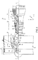
- Gas-turbine engine 20 may be a two-spool turbofan that generally incorporates a fan section 22, a compressor section 24, a combustor section 26 and a turbine section 28.
- Alternative engines may include, for example, an augmentor section among other systems or features.
- fan section 22 can drive coolant along a bypass flow-path B while compressor section 24 can drive coolant along a core flow-path C for compression and communication into combustor section 26 then expansion through turbine section 28.
- turbofan gas-turbine engine 20 depicted as a turbofan gas-turbine engine 20 herein, it should be understood that the concepts described herein are not limited to use with turbofans as the teachings may be applied to other types of turbine engines including three-spool architectures.
- Gas-turbine engine 20 may generally comprise a low speed spool 30 and a high speed spool 32 mounted for rotation about an engine central longitudinal axis A-A' relative to an engine static structure 36 via several bearing systems 38, 38-1, and 38-2.
- Engine central longitudinal axis A-A' is oriented in the z direction on the provided xyz axis.
- various bearing systems 38 at various locations may alternatively or additionally be provided, including for example, bearing system 38, bearing system 38-1, and bearing system 38-2.
- bearing system 38, bearing system 38-1, and bearing system 38-2 may be contained within a bearing housing and/or integrated into an oil delivery system, as described in further detail below.
- Low speed spool 30 may generally comprise an inner shaft 40 that interconnects a fan 42, a low pressure (or first) compressor section 44 and a low pressure (or first) turbine section 46.
- Inner shaft 40 may be connected to fan 42 through a geared architecture 48 that can drive fan 42 at a lower speed than low speed spool 30.
- Geared architecture 48 may comprise a gear assembly 60 enclosed within a gear housing 62.
- Gear assembly 60 couples inner shaft 40 to a rotating fan structure.
- High speed spool 32 may comprise an outer shaft 50 that interconnects a high pressure (or second) compressor 52 and high pressure (or second) turbine 54.
- a combustor 56 may be located between high pressure compressor 52 and high pressure turbine 54.
- a mid-turbine frame 57 of engine static structure 36 may be located generally between high pressure turbine 54 and low pressure turbine 46.
- Mid-turbine frame 57 may support one or more bearing systems 38 in turbine section 28.
- Inner shaft 40 and outer shaft 50 may be concentric and rotate via bearing systems 38 about the engine central longitudinal axis A-A', which is collinear with their longitudinal axes.
- a "high pressure" compressor or turbine experiences a higher pressure than a corresponding "low pressure” compressor or turbine.
- the core airflow C may be compressed by low pressure compressor section 44 then high pressure compressor 52, mixed and burned with fuel in combustor 56, then expanded over high pressure turbine 54 and low pressure turbine 46.
- Turbines 46, 54 rotationally drive the respective low speed spool 30 and high speed spool 32 in response to the expansion.
- Gas-turbine engine 20 may be, for example, a high-bypass ratio geared aircraft engine. In various embodiments, the bypass ratio of gas-turbine engine 20 may be greater than about six (6). In various embodiments, the bypass ratio of gas-turbine engine 20 may be greater than ten (10).
- geared architecture 48 may be an epicyclic gear train, such as a star gear system (sun gear in meshing engagement with a plurality of star gears supported by a carrier and in meshing engagement with a ring gear) or other gear system. Geared architecture 48 may have a gear reduction ratio of greater than about 2.3 and low pressure turbine 46 may have a pressure ratio that is greater than about five (5).
- the bypass ratio of gas-turbine engine 20 is greater than about ten (10:1).
- the diameter of fan 42 may be significantly larger than that of the low pressure compressor section 44, and the low pressure turbine 46 may have a pressure ratio that is greater than about five (5:1).
- Low pressure turbine 46 pressure ratio may be measured prior to inlet of low pressure turbine 46 as related to the pressure at the outlet of low pressure turbine 46 prior to an exhaust nozzle.
- Fan 42 may comprise blades that rotate about the engine central longitudinal axis A-A'.
- the blades may be airfoils coupled to a rotating hub by an attachment root.
- the attachment root of the blades have trenches or recesses that increase flexibility of the blades. In that regard, blades with trenches may absorb impact while limiting damage from any resulting strain.
- an attachment root 100 (e.g., of the blade of FIG. 1 ) is shown with a trench 104 formed in surface 102, in accordance with various embodiments.
- Attachment root 100 comprises a leading edge 106.
- Leading edge 106 may be disposed in a forward position relative to other portions of attachment root 100 when a blade is installed in an engine, with the remainder of attachment root 100 extending aft of leading edge 106.
- Trench 104 may thus be a recess extending aft from leading edge 106 in surface 102.
- Trench 104 may be a recess formed in a surface 102 of attachment root 100.
- Sidewall 112 may have a convex geometry matching the geometry of surface 102.
- sidewall 110 may have a concave geometry matching the geometry of surface 102.
- sidewall 110 and sidewall 112 may be spaced a uniform distance from the edge of surface 102.
- Trench 104 has an end surface 108 disposed at an interior area of surface 102. Trench 104 extends a length L 1 in an axial direction.
- attachment root 100 may comprise leading surface 120 at leading edge 106 of attachment root 100.
- a dovetail 122 of attachment root 100 may flare out in a circumferential direction to provide a contact surface and retain blade 43 using a dovetail-type joint.
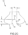
- Trench 104 may comprise a cylindrical trough 124 formed in surface 102 (i.e., the bottom surface of dovetail 122) and terminating at end surface 108 having a spherical geometry. Cylindrical trough 124 may have a width W 1 and join sidewall 110 and sidewall 112, with each sidewall extending tangentially away from cylindrical trough 124 and sidewall 110 being parallel to sidewall 112. Sidewall 112 and sidewall 110 may be oriented orthogonally to surface 102.
- Trench 104 may have a height H 1 from surface 102 into attachment root 100.
- the rounded contour of cylindrical trough 124 and the spherical contour of end surface 108 may limit stress concentrations in trench 104.
- trench 104 may be rectangular, trapezoidal, triangular, multi-radial, or any other shape to reduce strain concentrations resulting from impact events.
- height H 1 and width W 1 may be equal.
- height H 1 and width W 1 may each be a half inch (1.27 cm).
- the height H 1 , width W 1 , and length L 1 of trench 104 may be selected based on a desired flexibility. A greater height H 1 , width W 1 , and/or length L 1 will result in greater flexibility compared to a trench with smaller dimensions. In that regard, trench 104 having a greater volume may result in increased flexibility compared to a trench 104 having lower volume.
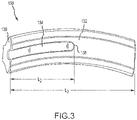
- attachment root 130 is shown with trench 134 in surface 132. Trench 134 extends from leading surface 136 to end surface 138 with the length L 2 of trench 134 being at least half length L 3 of attachment root 130.
- attachment root 150 is shown with a trench 154 offset a distance D 1 from leading edge 160 of attachment root 150.
- a full hoop of material around trench 154 with trench 154 offset from leading edge 160 may be stiffer than trench 104 (of FIG. 2A ) with an opening at the leading edge.
- a leading surface 156 of trench 154 may begin distance D 1 from leading edge 160.
- Leading surface 156 may be a spherical surface to limit stress concentrations.
- Trailing surface 158 of trench 154 may be a spherical similar to leading surface 156.
- Trench 154 may comprise a cylindrical trough extending between leading surface 156 and trailing surface 158.
- the length L 4 of trench 154 may be selected to achieve a suitable level of flexibility for attachment root 150.
- Trench 154 may have a cross section of the same shape and size as trench 104 in FIG. 2C .
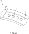
- attachment root 170 is shown with recesses 174 in surface 176.
- Recesses 174 may be disposed in a forward portion of surface 176. Recesses 174 may also be offset from leading edge 178 similar to trench 154 of FIG. 4A . Recesses 174 may further have a cross section as illustrated with reference to trench 104 in FIG. 2C .
- the walls 172 defining recess 174 are illustrated as circular and/or spherical, though a square geometry, rectangular geometry, elliptical geometry, or other shaped geometry may be effective as well.
- the circular geometries without sharp corners may experience lower stress concentrations than angular geometries.
- the numbers of and dimensions of recesses 174 may be selected to attain a suitable flexibility for attachment root 170.
- An attachment root with recesses formed in the attachment root may provide reduced strain concentrations in response to an impact event. Added flexibility may allow a fan blade to give and spread the impulse of the impact event over a greater time period at lower force. In that regard, an attachment root with a trench formed in the attachment root may be resistant to damage resulting from impact events.
- references to "various embodiments”, “one embodiment”, “an embodiment”, “an example embodiment”, etc. indicate that the embodiment described may include a particular feature, structure, or characteristic, but every embodiment may not necessarily include the particular feature, structure, or characteristic. Moreover, such phrases are not necessarily referring to the same embodiment. Further, when a particular feature, structure, or characteristic is described in connection with an embodiment, it is submitted that it is within the knowledge of one skilled in the art to affect such feature, structure, or characteristic in connection with other embodiments whether or not explicitly described. After reading the description, it will be apparent to one skilled in the relevant art(s) how to implement the disclosure in alternative embodiments.
Landscapes
- Engineering & Computer Science (AREA)
- Mechanical Engineering (AREA)
- General Engineering & Computer Science (AREA)
- Chemical & Material Sciences (AREA)
- Combustion & Propulsion (AREA)
- Structures Of Non-Positive Displacement Pumps (AREA)
Claims (7)
- Befestigungsfuß einer Gebläseschaufel (100; 130; 150) für einen Gasturbinenmotor, umfassend:eine Vorderkante (106; 160);einen Schwalbenschwanz (122), der sich hinter der Vorderkante (106; 160) erstreckt; undeine Vertiefung (104; 124; 134; 154), die in einer Bodenfläche des Schwalbenschwanzes (122) ausgebildet ist; dadurch gekennzeichnet, dass:
die Vertiefung (104; 124; 134) an einer Abschlussfläche (108; 138; 158) endet; die an einem Innenbereich der Oberfläche (102) des Schwalbenschwanzes (122) angeordnet ist, wobei eine axiale Länge (L1; L2) der Vertiefung (104; 124; 134; 154) kleiner ist als eine axiale Länge (L3) des Befestigungsfußes (100; 130; 150) und mindestens die Hälfte der axialen Länge (L3) des Befestigungsfußes (100; 130; 150). - Befestigungsfuß nach Anspruch 1, wobei die Vertiefung (104; 124; 134; 154) eine zylindrische Rinne (124) umfasst und die Abschlussfläche (108; 138; 158) eine sphärische Geometrie aufweist.
- Befestigungsfuß nach Anspruch 2, wobei die Vertiefung (104; 124; 134; 154) ferner eine erste Seitenwand (110) und eine zweite Seitenwand (112) parallel zu der ersten Seitenwand (110) umfasst, wobei die erste Seitenwand (110) und die zweite Seitenwand (112) tangential von der zylindrischen Rinne (124) ausgehen.
- Befestigungsfuß nach einem der vorhergehenden Ansprüche, wobei die Vertiefung (104; 124; 134; 154) von der Vorderkante (106; 160; 178) versetzt ist.
- Befestigungsfuß nach einem der vorhergehenden Ansprüche, wobei eine Höhe (H1) der Vertiefung (104; 124; 134; 154) gleich einer Breite (W1) der Vertiefung (104;124;134;154) ist.
- Gasturbinenmotor (20), umfassend:einen Kompressorabschnitt (24), der so konfiguriert ist, dass er sich um eine Achse (A-A') dreht;eine Brennkammer (56) hinter dem Kompressorabschnitt (24);einen Turbinenabschnitt (28) hinter der Brennkammer (56) und so konfiguriert, dass er sich um die Achse (A-A') dreht; undein Gebläse (22) vor dem Turbinenabschnitt (28), der eine Schaufel (42) und den Befestigungsfuß (100); 130; 150) nach einem der vorhergehenden Ansprüche umfasst.
- Gebläseschaufel (42), umfassend eine Vorderkante und den Befestigungsfuß (100; 130; 150) nach einem der Ansprüche 1 bis 5, wobei sich der Befestigungsfuß (100; 130) hinter der Vorderkante der Gebläseschaufel erstreckt.
Applications Claiming Priority (2)
| Application Number | Priority Date | Filing Date | Title |
|---|---|---|---|
| US201562167100P | 2015-05-27 | 2015-05-27 | |
| EP16171298.9A EP3098389B1 (de) | 2015-05-27 | 2016-05-25 | Gebläseschaufelbefestigungsfuss mit verbesserter belastungsreaktion |
Related Parent Applications (2)
| Application Number | Title | Priority Date | Filing Date |
|---|---|---|---|
| EP16171298.9A Division-Into EP3098389B1 (de) | 2015-05-27 | 2016-05-25 | Gebläseschaufelbefestigungsfuss mit verbesserter belastungsreaktion |
| EP16171298.9A Division EP3098389B1 (de) | 2015-05-27 | 2016-05-25 | Gebläseschaufelbefestigungsfuss mit verbesserter belastungsreaktion |
Publications (2)
| Publication Number | Publication Date |
|---|---|
| EP3587737A1 EP3587737A1 (de) | 2020-01-01 |
| EP3587737B1 true EP3587737B1 (de) | 2022-03-30 |
Family
ID=56080349
Family Applications (2)
| Application Number | Title | Priority Date | Filing Date |
|---|---|---|---|
| EP19190620.5A Active EP3587737B1 (de) | 2015-05-27 | 2016-05-25 | Befestigungsfuss einer gebläseschaufel mit verbesserter belastungsreaktion |
| EP16171298.9A Active EP3098389B1 (de) | 2015-05-27 | 2016-05-25 | Gebläseschaufelbefestigungsfuss mit verbesserter belastungsreaktion |
Family Applications After (1)
| Application Number | Title | Priority Date | Filing Date |
|---|---|---|---|
| EP16171298.9A Active EP3098389B1 (de) | 2015-05-27 | 2016-05-25 | Gebläseschaufelbefestigungsfuss mit verbesserter belastungsreaktion |
Country Status (2)
| Country | Link |
|---|---|
| US (3) | US10400784B2 (de) |
| EP (2) | EP3587737B1 (de) |
Families Citing this family (2)
| Publication number | Priority date | Publication date | Assignee | Title |
|---|---|---|---|---|
| FR3087479B1 (fr) * | 2018-10-23 | 2022-05-13 | Safran Aircraft Engines | Aube de turbomachine |
| KR102355521B1 (ko) | 2020-08-19 | 2022-01-24 | 두산중공업 주식회사 | 압축기 블레이드의 조립구조와 이를 포함하는 가스 터빈 및 압축기 블레이드의 조립방법 |
Citations (2)
| Publication number | Priority date | Publication date | Assignee | Title |
|---|---|---|---|---|
| US6065938A (en) * | 1996-06-21 | 2000-05-23 | Siemens Aktiengesellschaft | Rotor for a turbomachine having blades to be fitted into slots, and blade for a rotor |
| WO2014133613A2 (en) * | 2012-12-20 | 2014-09-04 | United Technologies Corporation | Fan blades for gas turbine engines with reduced stress concentration at leading edge |
Family Cites Families (21)
| Publication number | Priority date | Publication date | Assignee | Title |
|---|---|---|---|---|
| USRE33954E (en) * | 1982-02-22 | 1992-06-09 | United Technologies Corporation | Rotor blade assembly |
| US5100292A (en) * | 1990-03-19 | 1992-03-31 | General Electric Company | Gas turbine engine blade |
| US5314307A (en) * | 1992-12-18 | 1994-05-24 | Alliedsignal Inc. | Gas turbine test airfoil |
| US5435694A (en) | 1993-11-19 | 1995-07-25 | General Electric Company | Stress relieving mount for an axial blade |
| US5431542A (en) | 1994-04-29 | 1995-07-11 | United Technologies Corporation | Ramped dovetail rails for rotor blade assembly |
| EP1136654A1 (de) | 2000-03-21 | 2001-09-26 | Siemens Aktiengesellschaft | Turbinenlaufschaufel |
| US6739837B2 (en) * | 2002-04-16 | 2004-05-25 | United Technologies Corporation | Bladed rotor with a tiered blade to hub interface |
| US6786696B2 (en) * | 2002-05-06 | 2004-09-07 | General Electric Company | Root notched turbine blade |
| US6902376B2 (en) * | 2002-12-26 | 2005-06-07 | General Electric Company | Compressor blade with dovetail slotted to reduce stress on the airfoil leading edge |
| WO2006124615A1 (en) * | 2005-05-16 | 2006-11-23 | General Electric Company | Blade/disk dovetail backcut for blade/disk stress reduction (7fa+e, stage 1) |
| US7217099B2 (en) * | 2005-05-24 | 2007-05-15 | General Electric Company | Coated forward stub shaft dovetail slot |
| US7442007B2 (en) * | 2005-06-02 | 2008-10-28 | Pratt & Whitney Canada Corp. | Angled blade firtree retaining system |
| FR2889264B1 (fr) * | 2005-07-29 | 2007-11-02 | Snecma | Verrouillage des aubes dans un rotor de soufflante |
| GB2442968B (en) * | 2006-10-20 | 2009-08-19 | Rolls Royce Plc | A turbomachine rotor blade and a turbomachine rotor |
| EP2386721A1 (de) * | 2010-05-14 | 2011-11-16 | Siemens Aktiengesellschaft | Befestigungsanordnung für Schaufeln von axial durchströmbaren Turbomaschinen sowie Verfahren zum Herstellen einer solchen |
| US8727733B2 (en) * | 2011-05-26 | 2014-05-20 | General Electric Company | Gas turbine compressor last stage rotor blades with axial retention |
| US8764402B2 (en) * | 2011-06-09 | 2014-07-01 | General Electric Company | Turbomachine blade locking system |
| US9506356B2 (en) * | 2013-03-15 | 2016-11-29 | Rolls-Royce North American Technologies, Inc. | Composite retention feature |
| EP2981679B1 (de) | 2013-04-01 | 2020-08-26 | United Technologies Corporation | Rotor für einen gasturbinenmotor |
| US9765627B2 (en) | 2014-01-15 | 2017-09-19 | United Technologies Corporation | Root lightening holes with slot |
| US9777586B2 (en) * | 2014-12-31 | 2017-10-03 | General Electric Company | Flowpath boundary and rotor assemblies in gas turbines |
-
2016
- 2016-03-21 US US15/075,705 patent/US10400784B2/en active Active
- 2016-05-25 EP EP19190620.5A patent/EP3587737B1/de active Active
- 2016-05-25 EP EP16171298.9A patent/EP3098389B1/de active Active
-
2019
- 2019-01-11 US US16/245,484 patent/US10801515B2/en active Active
-
2020
- 2020-09-04 US US17/012,940 patent/US11002285B2/en active Active
Patent Citations (2)
| Publication number | Priority date | Publication date | Assignee | Title |
|---|---|---|---|---|
| US6065938A (en) * | 1996-06-21 | 2000-05-23 | Siemens Aktiengesellschaft | Rotor for a turbomachine having blades to be fitted into slots, and blade for a rotor |
| WO2014133613A2 (en) * | 2012-12-20 | 2014-09-04 | United Technologies Corporation | Fan blades for gas turbine engines with reduced stress concentration at leading edge |
Also Published As
| Publication number | Publication date |
|---|---|
| US20200025211A1 (en) | 2020-01-23 |
| US20200400159A1 (en) | 2020-12-24 |
| EP3098389B1 (de) | 2019-09-18 |
| US20160348689A1 (en) | 2016-12-01 |
| US10400784B2 (en) | 2019-09-03 |
| US10801515B2 (en) | 2020-10-13 |
| US11002285B2 (en) | 2021-05-11 |
| EP3587737A1 (de) | 2020-01-01 |
| EP3098389A1 (de) | 2016-11-30 |
Similar Documents
| Publication | Publication Date | Title |
|---|---|---|
| EP2872759B1 (de) | Mittelturbinenrahmen mit gewindespeichen | |
| EP3056740B1 (de) | Optimiertes casing treatment mit umfangsnut für axialverdichter | |
| US20140013770A1 (en) | Vane insertable tie rods with keyed connections | |
| EP3181824B1 (de) | Gasturbinenmotor | |
| EP3252271B1 (de) | Schaufelbausatz, zugehörige fanstufe und gasturbinentriebwerk | |
| US11002285B2 (en) | Fan blade attachment root with improved strain response | |
| EP2985421A1 (de) | Anordnung, verdichter und kühlsystem | |
| EP3018289A1 (de) | Gebläseschaufel mit statisch dissipativer beschichtung | |
| EP3045682B1 (de) | Zugstrebe für einen mittelturbinenrahmen | |
| EP3246517A1 (de) | Befestigungselementöffnungen zur spannungsverteilung | |
| EP3351727B1 (de) | Gasturbine | |
| EP3112615B1 (de) | Verdichterabschnitt mit einer besonderen anordnung zur haltung einer leitschaufel | |
| EP3296515B1 (de) | Statorschaufelanordnung mit einem verdrehsicheren plug | |
| EP2900980A2 (de) | Geometrie zur integration einer primären und sekundären düse eines getriebeturbolüfters | |
| EP3453835B1 (de) | Gebläseaustrittstatoranordnung | |
| EP3299587B1 (de) | Gasturbinenmotorschaufel | |
| EP2971613B1 (de) | Träger für nasenhaube | |
| US9771871B2 (en) | FBO torque reducing feature in fan shaft |
Legal Events
| Date | Code | Title | Description |
|---|---|---|---|
| PUAI | Public reference made under article 153(3) epc to a published international application that has entered the european phase |
Free format text: ORIGINAL CODE: 0009012 |
|
| STAA | Information on the status of an ep patent application or granted ep patent |
Free format text: STATUS: THE APPLICATION HAS BEEN PUBLISHED |
|
| AC | Divisional application: reference to earlier application |
Ref document number: 3098389 Country of ref document: EP Kind code of ref document: P |
|
| AK | Designated contracting states |
Kind code of ref document: A1 Designated state(s): AL AT BE BG CH CY CZ DE DK EE ES FI FR GB GR HR HU IE IS IT LI LT LU LV MC MK MT NL NO PL PT RO RS SE SI SK SM TR |
|
| STAA | Information on the status of an ep patent application or granted ep patent |
Free format text: STATUS: REQUEST FOR EXAMINATION WAS MADE |
|
| 17P | Request for examination filed |
Effective date: 20200701 |
|
| RBV | Designated contracting states (corrected) |
Designated state(s): AL AT BE BG CH CY CZ DE DK EE ES FI FR GB GR HR HU IE IS IT LI LT LU LV MC MK MT NL NO PL PT RO RS SE SI SK SM TR |
|
| STAA | Information on the status of an ep patent application or granted ep patent |
Free format text: STATUS: EXAMINATION IS IN PROGRESS |
|
| 17Q | First examination report despatched |
Effective date: 20201008 |
|
| RAP1 | Party data changed (applicant data changed or rights of an application transferred) |
Owner name: RAYTHEON TECHNOLOGIES CORPORATION |
|
| GRAP | Despatch of communication of intention to grant a patent |
Free format text: ORIGINAL CODE: EPIDOSNIGR1 |
|
| STAA | Information on the status of an ep patent application or granted ep patent |
Free format text: STATUS: GRANT OF PATENT IS INTENDED |
|
| INTG | Intention to grant announced |
Effective date: 20211008 |
|
| GRAS | Grant fee paid |
Free format text: ORIGINAL CODE: EPIDOSNIGR3 |
|
| GRAA | (expected) grant |
Free format text: ORIGINAL CODE: 0009210 |
|
| STAA | Information on the status of an ep patent application or granted ep patent |
Free format text: STATUS: THE PATENT HAS BEEN GRANTED |
|
| AC | Divisional application: reference to earlier application |
Ref document number: 3098389 Country of ref document: EP Kind code of ref document: P |
|
| AK | Designated contracting states |
Kind code of ref document: B1 Designated state(s): AL AT BE BG CH CY CZ DE DK EE ES FI FR GB GR HR HU IE IS IT LI LT LU LV MC MK MT NL NO PL PT RO RS SE SI SK SM TR |
|
| REG | Reference to a national code |
Ref country code: GB Ref legal event code: FG4D |
|
| REG | Reference to a national code |
Ref country code: CH Ref legal event code: EP |
|
| REG | Reference to a national code |
Ref country code: DE Ref legal event code: R096 Ref document number: 602016070667 Country of ref document: DE |
|
| REG | Reference to a national code |
Ref country code: AT Ref legal event code: REF Ref document number: 1479367 Country of ref document: AT Kind code of ref document: T Effective date: 20220415 |
|
| REG | Reference to a national code |
Ref country code: IE Ref legal event code: FG4D |
|
| REG | Reference to a national code |
Ref country code: LT Ref legal event code: MG9D |
|
| PG25 | Lapsed in a contracting state [announced via postgrant information from national office to epo] |
Ref country code: SE Free format text: LAPSE BECAUSE OF FAILURE TO SUBMIT A TRANSLATION OF THE DESCRIPTION OR TO PAY THE FEE WITHIN THE PRESCRIBED TIME-LIMIT Effective date: 20220330 Ref country code: RS Free format text: LAPSE BECAUSE OF FAILURE TO SUBMIT A TRANSLATION OF THE DESCRIPTION OR TO PAY THE FEE WITHIN THE PRESCRIBED TIME-LIMIT Effective date: 20220330 Ref country code: NO Free format text: LAPSE BECAUSE OF FAILURE TO SUBMIT A TRANSLATION OF THE DESCRIPTION OR TO PAY THE FEE WITHIN THE PRESCRIBED TIME-LIMIT Effective date: 20220630 Ref country code: LT Free format text: LAPSE BECAUSE OF FAILURE TO SUBMIT A TRANSLATION OF THE DESCRIPTION OR TO PAY THE FEE WITHIN THE PRESCRIBED TIME-LIMIT Effective date: 20220330 Ref country code: HR Free format text: LAPSE BECAUSE OF FAILURE TO SUBMIT A TRANSLATION OF THE DESCRIPTION OR TO PAY THE FEE WITHIN THE PRESCRIBED TIME-LIMIT Effective date: 20220330 Ref country code: BG Free format text: LAPSE BECAUSE OF FAILURE TO SUBMIT A TRANSLATION OF THE DESCRIPTION OR TO PAY THE FEE WITHIN THE PRESCRIBED TIME-LIMIT Effective date: 20220630 |
|
| REG | Reference to a national code |
Ref country code: NL Ref legal event code: MP Effective date: 20220330 |
|
| REG | Reference to a national code |
Ref country code: AT Ref legal event code: MK05 Ref document number: 1479367 Country of ref document: AT Kind code of ref document: T Effective date: 20220330 |
|
| PG25 | Lapsed in a contracting state [announced via postgrant information from national office to epo] |
Ref country code: LV Free format text: LAPSE BECAUSE OF FAILURE TO SUBMIT A TRANSLATION OF THE DESCRIPTION OR TO PAY THE FEE WITHIN THE PRESCRIBED TIME-LIMIT Effective date: 20220330 Ref country code: GR Free format text: LAPSE BECAUSE OF FAILURE TO SUBMIT A TRANSLATION OF THE DESCRIPTION OR TO PAY THE FEE WITHIN THE PRESCRIBED TIME-LIMIT Effective date: 20220701 Ref country code: FI Free format text: LAPSE BECAUSE OF FAILURE TO SUBMIT A TRANSLATION OF THE DESCRIPTION OR TO PAY THE FEE WITHIN THE PRESCRIBED TIME-LIMIT Effective date: 20220330 |
|
| PG25 | Lapsed in a contracting state [announced via postgrant information from national office to epo] |
Ref country code: NL Free format text: LAPSE BECAUSE OF FAILURE TO SUBMIT A TRANSLATION OF THE DESCRIPTION OR TO PAY THE FEE WITHIN THE PRESCRIBED TIME-LIMIT Effective date: 20220330 |
|
| PG25 | Lapsed in a contracting state [announced via postgrant information from national office to epo] |
Ref country code: SM Free format text: LAPSE BECAUSE OF FAILURE TO SUBMIT A TRANSLATION OF THE DESCRIPTION OR TO PAY THE FEE WITHIN THE PRESCRIBED TIME-LIMIT Effective date: 20220330 Ref country code: SK Free format text: LAPSE BECAUSE OF FAILURE TO SUBMIT A TRANSLATION OF THE DESCRIPTION OR TO PAY THE FEE WITHIN THE PRESCRIBED TIME-LIMIT Effective date: 20220330 Ref country code: RO Free format text: LAPSE BECAUSE OF FAILURE TO SUBMIT A TRANSLATION OF THE DESCRIPTION OR TO PAY THE FEE WITHIN THE PRESCRIBED TIME-LIMIT Effective date: 20220330 Ref country code: PT Free format text: LAPSE BECAUSE OF FAILURE TO SUBMIT A TRANSLATION OF THE DESCRIPTION OR TO PAY THE FEE WITHIN THE PRESCRIBED TIME-LIMIT Effective date: 20220801 Ref country code: ES Free format text: LAPSE BECAUSE OF FAILURE TO SUBMIT A TRANSLATION OF THE DESCRIPTION OR TO PAY THE FEE WITHIN THE PRESCRIBED TIME-LIMIT Effective date: 20220330 Ref country code: EE Free format text: LAPSE BECAUSE OF FAILURE TO SUBMIT A TRANSLATION OF THE DESCRIPTION OR TO PAY THE FEE WITHIN THE PRESCRIBED TIME-LIMIT Effective date: 20220330 Ref country code: CZ Free format text: LAPSE BECAUSE OF FAILURE TO SUBMIT A TRANSLATION OF THE DESCRIPTION OR TO PAY THE FEE WITHIN THE PRESCRIBED TIME-LIMIT Effective date: 20220330 Ref country code: AT Free format text: LAPSE BECAUSE OF FAILURE TO SUBMIT A TRANSLATION OF THE DESCRIPTION OR TO PAY THE FEE WITHIN THE PRESCRIBED TIME-LIMIT Effective date: 20220330 |
|
| PG25 | Lapsed in a contracting state [announced via postgrant information from national office to epo] |
Ref country code: PL Free format text: LAPSE BECAUSE OF FAILURE TO SUBMIT A TRANSLATION OF THE DESCRIPTION OR TO PAY THE FEE WITHIN THE PRESCRIBED TIME-LIMIT Effective date: 20220330 Ref country code: IS Free format text: LAPSE BECAUSE OF FAILURE TO SUBMIT A TRANSLATION OF THE DESCRIPTION OR TO PAY THE FEE WITHIN THE PRESCRIBED TIME-LIMIT Effective date: 20220730 Ref country code: AL Free format text: LAPSE BECAUSE OF FAILURE TO SUBMIT A TRANSLATION OF THE DESCRIPTION OR TO PAY THE FEE WITHIN THE PRESCRIBED TIME-LIMIT Effective date: 20220330 |
|
| REG | Reference to a national code |
Ref country code: CH Ref legal event code: PL |
|
| REG | Reference to a national code |
Ref country code: DE Ref legal event code: R097 Ref document number: 602016070667 Country of ref document: DE |
|
| REG | Reference to a national code |
Ref country code: BE Ref legal event code: MM Effective date: 20220531 |
|
| PG25 | Lapsed in a contracting state [announced via postgrant information from national office to epo] |
Ref country code: MC Free format text: LAPSE BECAUSE OF FAILURE TO SUBMIT A TRANSLATION OF THE DESCRIPTION OR TO PAY THE FEE WITHIN THE PRESCRIBED TIME-LIMIT Effective date: 20220330 Ref country code: LU Free format text: LAPSE BECAUSE OF NON-PAYMENT OF DUE FEES Effective date: 20220525 Ref country code: LI Free format text: LAPSE BECAUSE OF NON-PAYMENT OF DUE FEES Effective date: 20220531 Ref country code: DK Free format text: LAPSE BECAUSE OF FAILURE TO SUBMIT A TRANSLATION OF THE DESCRIPTION OR TO PAY THE FEE WITHIN THE PRESCRIBED TIME-LIMIT Effective date: 20220330 Ref country code: CH Free format text: LAPSE BECAUSE OF NON-PAYMENT OF DUE FEES Effective date: 20220531 |
|
| PLBE | No opposition filed within time limit |
Free format text: ORIGINAL CODE: 0009261 |
|
| STAA | Information on the status of an ep patent application or granted ep patent |
Free format text: STATUS: NO OPPOSITION FILED WITHIN TIME LIMIT |
|
| 26N | No opposition filed |
Effective date: 20230103 |
|
| PG25 | Lapsed in a contracting state [announced via postgrant information from national office to epo] |
Ref country code: IE Free format text: LAPSE BECAUSE OF NON-PAYMENT OF DUE FEES Effective date: 20220525 |
|
| PG25 | Lapsed in a contracting state [announced via postgrant information from national office to epo] |
Ref country code: SI Free format text: LAPSE BECAUSE OF FAILURE TO SUBMIT A TRANSLATION OF THE DESCRIPTION OR TO PAY THE FEE WITHIN THE PRESCRIBED TIME-LIMIT Effective date: 20220330 Ref country code: BE Free format text: LAPSE BECAUSE OF NON-PAYMENT OF DUE FEES Effective date: 20220531 |
|
| P01 | Opt-out of the competence of the unified patent court (upc) registered |
Effective date: 20230521 |
|
| PG25 | Lapsed in a contracting state [announced via postgrant information from national office to epo] |
Ref country code: IT Free format text: LAPSE BECAUSE OF FAILURE TO SUBMIT A TRANSLATION OF THE DESCRIPTION OR TO PAY THE FEE WITHIN THE PRESCRIBED TIME-LIMIT Effective date: 20220330 |
|
| PG25 | Lapsed in a contracting state [announced via postgrant information from national office to epo] |
Ref country code: MK Free format text: LAPSE BECAUSE OF FAILURE TO SUBMIT A TRANSLATION OF THE DESCRIPTION OR TO PAY THE FEE WITHIN THE PRESCRIBED TIME-LIMIT Effective date: 20220330 Ref country code: CY Free format text: LAPSE BECAUSE OF FAILURE TO SUBMIT A TRANSLATION OF THE DESCRIPTION OR TO PAY THE FEE WITHIN THE PRESCRIBED TIME-LIMIT Effective date: 20220330 |
|
| PG25 | Lapsed in a contracting state [announced via postgrant information from national office to epo] |
Ref country code: HU Free format text: LAPSE BECAUSE OF FAILURE TO SUBMIT A TRANSLATION OF THE DESCRIPTION OR TO PAY THE FEE WITHIN THE PRESCRIBED TIME-LIMIT; INVALID AB INITIO Effective date: 20160525 |
|
| PG25 | Lapsed in a contracting state [announced via postgrant information from national office to epo] |
Ref country code: TR Free format text: LAPSE BECAUSE OF FAILURE TO SUBMIT A TRANSLATION OF THE DESCRIPTION OR TO PAY THE FEE WITHIN THE PRESCRIBED TIME-LIMIT Effective date: 20220330 |
|
| PG25 | Lapsed in a contracting state [announced via postgrant information from national office to epo] |
Ref country code: MT Free format text: LAPSE BECAUSE OF FAILURE TO SUBMIT A TRANSLATION OF THE DESCRIPTION OR TO PAY THE FEE WITHIN THE PRESCRIBED TIME-LIMIT Effective date: 20220330 |
|
| PGFP | Annual fee paid to national office [announced via postgrant information from national office to epo] |
Ref country code: DE Payment date: 20250423 Year of fee payment: 10 |
|
| PGFP | Annual fee paid to national office [announced via postgrant information from national office to epo] |
Ref country code: GB Payment date: 20250423 Year of fee payment: 10 |
|
| PGFP | Annual fee paid to national office [announced via postgrant information from national office to epo] |
Ref country code: FR Payment date: 20250423 Year of fee payment: 10 |
|
| REG | Reference to a national code |
Ref country code: DE Ref legal event code: R081 Ref document number: 602016070667 Country of ref document: DE Owner name: RTX CORPORATION (N.D.GES.D. STAATES DELAWARE),, US Free format text: FORMER OWNER: RAYTHEON TECHNOLOGIES CORPORATION, FARMINGTON, CT, US |