EP3587193A1 - Wire harness and power supply device having the same - Google Patents
Wire harness and power supply device having the same Download PDFInfo
- Publication number
- EP3587193A1 EP3587193A1 EP19175826.7A EP19175826A EP3587193A1 EP 3587193 A1 EP3587193 A1 EP 3587193A1 EP 19175826 A EP19175826 A EP 19175826A EP 3587193 A1 EP3587193 A1 EP 3587193A1
- Authority
- EP
- European Patent Office
- Prior art keywords
- wire harness
- connecting portion
- restricting member
- sliding door
- curvature
- Prior art date
- Legal status (The legal status is an assumption and is not a legal conclusion. Google has not performed a legal analysis and makes no representation as to the accuracy of the status listed.)
- Granted
Links
Images


Classifications
-
- H—ELECTRICITY
- H02—GENERATION; CONVERSION OR DISTRIBUTION OF ELECTRIC POWER
- H02G—INSTALLATION OF ELECTRIC CABLES OR LINES, OR OF COMBINED OPTICAL AND ELECTRIC CABLES OR LINES
- H02G11/00—Arrangements of electric cables or lines between relatively-movable parts
-
- B—PERFORMING OPERATIONS; TRANSPORTING
- B60—VEHICLES IN GENERAL
- B60R—VEHICLES, VEHICLE FITTINGS, OR VEHICLE PARTS, NOT OTHERWISE PROVIDED FOR
- B60R16/00—Electric or fluid circuits specially adapted for vehicles and not otherwise provided for; Arrangement of elements of electric or fluid circuits specially adapted for vehicles and not otherwise provided for
- B60R16/02—Electric or fluid circuits specially adapted for vehicles and not otherwise provided for; Arrangement of elements of electric or fluid circuits specially adapted for vehicles and not otherwise provided for electric constitutive elements
- B60R16/0207—Wire harnesses
- B60R16/0215—Protecting, fastening and routing means therefor
-
- B—PERFORMING OPERATIONS; TRANSPORTING
- B60—VEHICLES IN GENERAL
- B60J—WINDOWS, WINDSCREENS, NON-FIXED ROOFS, DOORS, OR SIMILAR DEVICES FOR VEHICLES; REMOVABLE EXTERNAL PROTECTIVE COVERINGS SPECIALLY ADAPTED FOR VEHICLES
- B60J5/00—Doors
- B60J5/04—Doors arranged at the vehicle sides
- B60J5/06—Doors arranged at the vehicle sides slidable; foldable
-
- B—PERFORMING OPERATIONS; TRANSPORTING
- B60—VEHICLES IN GENERAL
- B60R—VEHICLES, VEHICLE FITTINGS, OR VEHICLE PARTS, NOT OTHERWISE PROVIDED FOR
- B60R16/00—Electric or fluid circuits specially adapted for vehicles and not otherwise provided for; Arrangement of elements of electric or fluid circuits specially adapted for vehicles and not otherwise provided for
- B60R16/02—Electric or fluid circuits specially adapted for vehicles and not otherwise provided for; Arrangement of elements of electric or fluid circuits specially adapted for vehicles and not otherwise provided for electric constitutive elements
- B60R16/0207—Wire harnesses
-
- B—PERFORMING OPERATIONS; TRANSPORTING
- B60—VEHICLES IN GENERAL
- B60R—VEHICLES, VEHICLE FITTINGS, OR VEHICLE PARTS, NOT OTHERWISE PROVIDED FOR
- B60R16/00—Electric or fluid circuits specially adapted for vehicles and not otherwise provided for; Arrangement of elements of electric or fluid circuits specially adapted for vehicles and not otherwise provided for
- B60R16/02—Electric or fluid circuits specially adapted for vehicles and not otherwise provided for; Arrangement of elements of electric or fluid circuits specially adapted for vehicles and not otherwise provided for electric constitutive elements
- B60R16/023—Electric or fluid circuits specially adapted for vehicles and not otherwise provided for; Arrangement of elements of electric or fluid circuits specially adapted for vehicles and not otherwise provided for electric constitutive elements for transmission of signals between vehicle parts or subsystems
- B60R16/027—Electric or fluid circuits specially adapted for vehicles and not otherwise provided for; Arrangement of elements of electric or fluid circuits specially adapted for vehicles and not otherwise provided for electric constitutive elements for transmission of signals between vehicle parts or subsystems between relatively movable parts of the vehicle, e.g. between steering wheel and column
-
- H—ELECTRICITY
- H02—GENERATION; CONVERSION OR DISTRIBUTION OF ELECTRIC POWER
- H02G—INSTALLATION OF ELECTRIC CABLES OR LINES, OR OF COMBINED OPTICAL AND ELECTRIC CABLES OR LINES
- H02G3/00—Installations of electric cables or lines or protective tubing therefor in or on buildings, equivalent structures or vehicles
- H02G3/02—Details
- H02G3/04—Protective tubing or conduits, e.g. cable ladders or cable troughs
- H02G3/0456—Ladders or other supports
Definitions
- the present invention relates to a wire harness mounted on a motor vehicle and configured to supply power and/or transmit a signal from a vehicle body to an electric component on a sliding door.
- FIG. 6 is an illustration illustrating a trajectory of a wire harness of a conventional power supply device (for example, refer to Patent Documents 1 and 2 listed below).
- a power supply device 401 shown in FIG. 6 includes a wire harness 404 wired from a vehicle body to a sliding door, a body-side unit 402 and a door-side unit 403.
- the body-side unit 402 supports a corrugated tube 51 as an exterior member of the wire harness 404 on the vehicle body side such that the corrugated tube 51 is rotatable around an axis line P1.
- the door-side unit 403 supports the corrugated tube 51 on the sliding door side such that the corrugated tube 51 is rotatable around an axis line P2.
- an arrow X is parallel to a width direction of a vehicle
- an arrow Y is parallel to a front-rear direction of the vehicle
- an arrow Z is parallel to a vertical direction of the vehicle.
- the door-side unit in a fully-closed state of the sliding door is denoted by a reference sign 403A
- the wire harness in the fully-closed state of the sliding door is denoted by a reference sign 404A.
- the door-side unit in the beginning of opening of the sliding door is denoted by a reference sign 403B
- the wire harness in the beginning of opening of the sliding door is denoted by a reference sign 404B.
- the door-side unit in a half-opened state of the sliding door is denoted by a reference sign 403C
- the wire harness in the half-opened state of the sliding door is denoted by a reference sign 404C.
- the door-side unit in a fully-opened state of the sliding door is denoted by a reference sign 403D
- the wire harness in the fully-opened state of the sliding door is denoted by a reference sign 404D.
- the power supply device 401 includes a curvature restricting member that is inserted in the corrugated tube 51 and/or includes a spring arranged in the body-side unit 402 and the door-side unit 403. As such, as shown in FIG.
- a portion of the wire harness 404C in the vicinity of the body-side unit 402 extends in the front-rear direction of the vehicle and is prevented from swelling to the vehicle body side.
- the wire harness 404C in the half-opened state of the sliding door is prevented from swelling to the vehicle body side. On the other side, however, swelling of the wire harness 404B in the beginning of the opening of the sliding door (that is a portion G in FIG. 6 ) is not prevented.
- an object of the present invention is to prevent a wire harness from swelling to a vehicle body side in the beginning of opening of a sliding door.
- the present invention provides a wire harness to be wired from a vehicle body to a sliding door of a motor vehicle, including an electric wire and a curvature restricting member, wherein the curvature restricting member includes a connecting portion extending in a strip-like fashion in a length direction of the electric wire, and a plurality of pieces upwardly extending from one widthwise end or both widthwise ends of the connecting portion and arranged in a length direction of the connecting portion, the curvature restricting member is capable of being curved in an orientation in which the connecting portion is arranged inside and the pieces are arranged outside, and in an inverse orientation, curvature of the curvature restricting member is limited by adjacent pieces being abutted onto each other, and the connecting portion includes a portion with high flexibility and a portion with low flexibility, in which a portion in vicinity of the sliding door has high flexibility.
- the connecting portion has the portion with high flexibility and the portion with low flexibility, and the portion in the vicinity of the sliding door has high flexibility.
- rigidity of the portion of the wire harness in the vicinity of the sliding door can be made smaller compared to the other portion of the wire harness, thereby preventing the wire harness from swelling to the vehicle body side in the beginning of the sliding door.
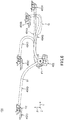
- a power supply device 1 shown in FIG. 1 is configured to be mounted on a motor vehicle and configured to supply power and/or transmit a signal from a vehicle body to an electric component on a sliding door.
- the power supply device 1 includes a wire harness 4 to be wired from the vehicle body to the sliding door, a body-side unit 2 rotatably supporting an exterior member 5 of the wire harness 4 on the vehicle body side, and a door-side unit 3 rotatably supporting the exterior member 5 on the sliding door side.
- FIG. 1 illustrates a form of the power supply device 1 in the beginning of opening of the sliding door, in which a relative position of the body-side unit 2 and the door-side unit 3 corresponds to a relative position of the body-side unit 402 and the door-side unit 403B of the conventional power supply device 4 in FIG. 6 .
- a trajectory of the door-side unit 3 from a fully-closed state of the sliding door to a fully-opened state of the sliding door is the same as the conventional example of FIG. 6 .
- a trajectory of the wire harness 4 from the fully-closed state of the sliding door to the fully-opened state of the sliding door is substantially the same as the conventional example of FIG. 6 , except for the beginning of the opening of the sliding door that is shown in FIG. 1 .
- an arrow X is parallel to a width direction of the vehicle
- an arrow Y is parallel to a front-rear direction of the vehicle
- an arrow Z is parallel to a vertical direction of the vehicle.
- the sliding door is configured to slide in the front-rear direction of the vehicle.
- the wire harness 4 includes a plurality of electric wires 7, a curvature restricting member 6 shown in FIGS. 2 and 3 , and the exterior member 5 covering the electric wires 7 and the curvature restricting member 6.
- the exterior member 5 and the curvature restricting member 6 are provided in a range from the body-side unit 2 to the door-side unit 3.
- the electric wire 7 is formed longer than the exterior member 5, and both ends of the electric wires 7 are drawn out from the exterior member 5 and are exposed.
- the curvature restricting member 6 includes a connecting portion 65 extending in a strip-like fashion in a length direction of the electric wire 7, and a plurality of pieces 61 upwardly extending from both widthwise ends of the connecting portion 65 and arranged in a length direction of the connecting portion 65.
- the connecting portion 65 and the plurality of pieces 61 are integrally formed using synthetic resin.
- a first end of the curvature restricting member 6 in the length direction is provided with a flange 69 held by the body-side unit 2.
- a second end of the curvature restricting member 6 in the length direction is a free end which is not held by the door-side unit 3.
- Each piece 61 includes a plate portion 62 formed into a rectangular plate-like shape, and a neck portion 63 projecting from an outer edge of the plate portion 62.
- An outer surface of the plate portion 62 is provided with a reinforcement rib 64.
- the neck portion 63 is a portion of the piece 61 that is connected to the connecting portion 65 and has a width smaller than that of the plate portion 62.
- the curvature restricting member 6 is capable of being curved in an orientation in which the connecting portion 65 is arranged inside and the pieces 61 are arranged outside, with the adjacent pieces 61 separating away from each other while the connecting portion 65 being elastically deformed. In an inverse orientation, curvature of the curvature restricting member 6 is limited by the plate portions 62 of the adjacent pieces 61 being abutted onto each other.
- the first end side (i.e., the body-side unit 2 side) of the curvature restricting member 6 is arranged such that a gap exists between the adjacent plate portions 62 when the connecting portion 65 is positioned in a straight line, and the remaining portion of the curvature restricting member 6 is arranged such that the adjacent plate portions 62 abut onto each other when the connecting portion 65 is positioned in a straight line.
- the first end side of the curvature restricting member 6 is capable of being slightly curved in an orientation in which the connecting portion 65 is arranged outside and the pieces 61 are arranged inside.
- the curvature restricting member 6 is arranged in an orientation in which the width direction of the connecting portion 65 corresponds to the Z direction of FIG. 1 and the connecting portion 65 is positioned outside in the vehicle width direction with respect to the pieces 61 in the fully-closed state of the sliding door.
- the electric wires 7 are positioned between the pieces 61 arranged opposed to each other in the width direction of the connecting portion 65.
- the connecting portion 65 includes a portion with high flexibility and a portion with low flexibility, in which a portion in the vicinity of the sliding door has high flexibility.
- a portion D shown in FIG. 3 located at the second end side in the length direction of the curvature restricting member 6 has flexibility higher than a portion C located at the first end side of the curvature restricting member 6.
- a thickness T2 of the connecting portion 65 in the portion D is made thinner than a thickness T1 of the connecting portion 65 in the portion C, thereby increasing the flexibility of the connecting portion 65 in the portion D compared to the connecting portion 65 in the portion C.
- the length of the connecting portion 65 in the portion D corresponds to about 20% of an entire length of the curvature restricting member 6.
- the body-side unit 2 includes a body rotor 21 attached to a first end of the exterior member 5, and a body protector 22 which is fixed to the vehicle body and to which the body rotor 21 is attached so as to rotate around an axis line P1.
- the door-side unit 3 includes a door rotor 31 attached to a second end of the exterior member 5, a door protector 32 which is fixed to the sliding door and to which the door rotor 31 is attached so as to rotate around an axis line P2, and a spring configured to bias the door rotor 31 in the counterclockwise direction in a plan view of FIG. 1 .
- the wire harness 4 since the wire harness 4 includes the curvature restricting member 6 described above, rigidity of the portion of the wire harness 4 in the vicinity of the door-side unit 3 can be made smaller compared to the other portion of the wire harness 4, thereby preventing the wire harness 4 from swelling to the vehicle body side in the beginning of opening of the sliding door. Consequently, interference between the wire harness 4 and the vehicle body can be prevented, and also, deterioration of appearance due to the swelling of the wire harness 4 can be avoided.
- a dotted line indicates a wire harness of a comparative example.
- a curvature restricting member includes a connecting portion 65 having the flexibility that is uniform across the entire length thereof. As can be seen from FIG. 1 , by using the curvature restricting member 6 of this embodiment, the swelling of the wire harness 4 in the beginning of opening of the sliding door can be reduced.
- the wire harness 4 of the above-described embodiment includes the exterior member 5
- the wire harness of the present invention may not necessarily include the exterior member.
- the curvature restricting member 6 of the above-described embodiment includes the pieces 61 extending upwardly from the both widthwise ends of the connecting portion 65
- the curvature restricting member of the present invention may include the pieces 61 extending upwardly from only one widthwise end of the connecting portion 65.
Landscapes
- Engineering & Computer Science (AREA)
- Mechanical Engineering (AREA)
- Architecture (AREA)
- Civil Engineering (AREA)
- Structural Engineering (AREA)
- Electric Cable Arrangement Between Relatively Moving Parts (AREA)
Abstract
Description
- The present invention relates to a wire harness mounted on a motor vehicle and configured to supply power and/or transmit a signal from a vehicle body to an electric component on a sliding door.
- Conventionally, a motor vehicle having a sliding door is mounted with a power supply device configured to supply power and/or transmit a signal from a vehicle body to an electric component on the sliding door.
FIG. 6 is an illustration illustrating a trajectory of a wire harness of a conventional power supply device (for example, refer toPatent Documents - A
power supply device 401 shown inFIG. 6 includes a wire harness 404 wired from a vehicle body to a sliding door, a body-side unit 402 and a door-side unit 403. The body-side unit 402 supports acorrugated tube 51 as an exterior member of the wire harness 404 on the vehicle body side such that thecorrugated tube 51 is rotatable around an axis line P1. The door-side unit 403 supports thecorrugated tube 51 on the sliding door side such that thecorrugated tube 51 is rotatable around an axis line P2. InFIG. 6 , an arrow X is parallel to a width direction of a vehicle, an arrow Y is parallel to a front-rear direction of the vehicle, and an arrow Z is parallel to a vertical direction of the vehicle. - In
FIG. 6 , the door-side unit in a fully-closed state of the sliding door is denoted by areference sign 403A, and the wire harness in the fully-closed state of the sliding door is denoted by areference sign 404A. Further, the door-side unit in the beginning of opening of the sliding door is denoted by areference sign 403B, and the wire harness in the beginning of opening of the sliding door is denoted by areference sign 404B. Further, the door-side unit in a half-opened state of the sliding door is denoted by areference sign 403C, and the wire harness in the half-opened state of the sliding door is denoted by areference sign 404C. Further, the door-side unit in a fully-opened state of the sliding door is denoted by areference sign 403D, and the wire harness in the fully-opened state of the sliding door is denoted by areference sign 404D. - In this
power supply device 401, there is a problem that the wire harness 404 curved due to the opening and closing of the sliding door is swelled to the vehicle body side, and this swelling of the wire harness needs to be prevented. This is because if the wire harness 404 is swelled to the vehicle body side, then the wire harness 404 is more likely to interfere with the vehicle body and/or appearance is deteriorated. To address this problem, thepower supply device 401 includes a curvature restricting member that is inserted in thecorrugated tube 51 and/or includes a spring arranged in the body-side unit 402 and the door-side unit 403. As such, as shown inFIG. 6 , for thewire harness 404C in the half-opened state of the sliding door, a portion of thewire harness 404C in the vicinity of the body-side unit 402 extends in the front-rear direction of the vehicle and is prevented from swelling to the vehicle body side. -
- Patent Document 1:
JP 2017-192258 A - Patent Document 2:
JP 2017-192259 A - As described above, in the conventional
power supply device 401, thewire harness 404C in the half-opened state of the sliding door is prevented from swelling to the vehicle body side. On the other side, however, swelling of thewire harness 404B in the beginning of the opening of the sliding door (that is a portion G inFIG. 6 ) is not prevented. - In view of the above-described problem, an object of the present invention is to prevent a wire harness from swelling to a vehicle body side in the beginning of opening of a sliding door. Solution to Problem
- In order to achieve the above-described object, the present invention provides a wire harness to be wired from a vehicle body to a sliding door of a motor vehicle, including an electric wire and a curvature restricting member, wherein the curvature restricting member includes a connecting portion extending in a strip-like fashion in a length direction of the electric wire, and a plurality of pieces upwardly extending from one widthwise end or both widthwise ends of the connecting portion and arranged in a length direction of the connecting portion, the curvature restricting member is capable of being curved in an orientation in which the connecting portion is arranged inside and the pieces are arranged outside, and in an inverse orientation, curvature of the curvature restricting member is limited by adjacent pieces being abutted onto each other, and the connecting portion includes a portion with high flexibility and a portion with low flexibility, in which a portion in vicinity of the sliding door has high flexibility.
- According to the present invention, the connecting portion has the portion with high flexibility and the portion with low flexibility, and the portion in the vicinity of the sliding door has high flexibility. Thus, rigidity of the portion of the wire harness in the vicinity of the sliding door can be made smaller compared to the other portion of the wire harness, thereby preventing the wire harness from swelling to the vehicle body side in the beginning of the sliding door.
-
-
FIG. 1 is a plan view of a power supply device according to one embodiment of the present invention; -
FIG. 2 is a perspective view of a curvature restricting member constituting a wire harness ofFIG. 1 ; -
FIG. 3 is a side view of the curvature restricting member ofFIG. 2 ; -
FIG. 4 is a cross-sectional view taken along a line A-A inFIG. 3 ; -
FIG. 5 is a cross-sectional view taken along a line B-B inFIG. 3 ; and -
FIG. 6 is an illustration illustrating a trajectory of a wire harness of a conventional power supply device. - In the following, "wire harness" and "power supply device" according to one embodiment of the present invention will be explained with reference to
FIGS. 1 to 5 . - A
power supply device 1 shown inFIG. 1 is configured to be mounted on a motor vehicle and configured to supply power and/or transmit a signal from a vehicle body to an electric component on a sliding door. Thepower supply device 1 includes awire harness 4 to be wired from the vehicle body to the sliding door, a body-side unit 2 rotatably supporting anexterior member 5 of thewire harness 4 on the vehicle body side, and a door-side unit 3 rotatably supporting theexterior member 5 on the sliding door side. -
FIG. 1 illustrates a form of thepower supply device 1 in the beginning of opening of the sliding door, in which a relative position of the body-side unit 2 and the door-side unit 3 corresponds to a relative position of the body-side unit 402 and the door-side unit 403B of the conventionalpower supply device 4 inFIG. 6 . A trajectory of the door-side unit 3 from a fully-closed state of the sliding door to a fully-opened state of the sliding door is the same as the conventional example ofFIG. 6 . Further, a trajectory of thewire harness 4 from the fully-closed state of the sliding door to the fully-opened state of the sliding door is substantially the same as the conventional example ofFIG. 6 , except for the beginning of the opening of the sliding door that is shown inFIG. 1 . InFIG. 1 , an arrow X is parallel to a width direction of the vehicle, an arrow Y is parallel to a front-rear direction of the vehicle, and an arrow Z is parallel to a vertical direction of the vehicle. The sliding door is configured to slide in the front-rear direction of the vehicle. - The
wire harness 4 includes a plurality ofelectric wires 7, acurvature restricting member 6 shown inFIGS. 2 and3 , and theexterior member 5 covering theelectric wires 7 and thecurvature restricting member 6. Theexterior member 5 and thecurvature restricting member 6 are provided in a range from the body-side unit 2 to the door-side unit 3. Theelectric wire 7 is formed longer than theexterior member 5, and both ends of theelectric wires 7 are drawn out from theexterior member 5 and are exposed. As theexterior member 5, a known corrugated tube formed into a concertina tube-like shape may be used. - The
curvature restricting member 6 includes a connectingportion 65 extending in a strip-like fashion in a length direction of theelectric wire 7, and a plurality ofpieces 61 upwardly extending from both widthwise ends of the connectingportion 65 and arranged in a length direction of the connectingportion 65. The connectingportion 65 and the plurality ofpieces 61 are integrally formed using synthetic resin. A first end of thecurvature restricting member 6 in the length direction is provided with aflange 69 held by the body-side unit 2. A second end of thecurvature restricting member 6 in the length direction is a free end which is not held by the door-side unit 3. - Each
piece 61 includes aplate portion 62 formed into a rectangular plate-like shape, and aneck portion 63 projecting from an outer edge of theplate portion 62. An outer surface of theplate portion 62 is provided with areinforcement rib 64. Theneck portion 63 is a portion of thepiece 61 that is connected to the connectingportion 65 and has a width smaller than that of theplate portion 62. - As shown in
FIGS. 2 and3 , thecurvature restricting member 6 is capable of being curved in an orientation in which the connectingportion 65 is arranged inside and thepieces 61 are arranged outside, with theadjacent pieces 61 separating away from each other while the connectingportion 65 being elastically deformed. In an inverse orientation, curvature of thecurvature restricting member 6 is limited by theplate portions 62 of theadjacent pieces 61 being abutted onto each other. Further, the first end side (i.e., the body-side unit 2 side) of thecurvature restricting member 6 is arranged such that a gap exists between theadjacent plate portions 62 when the connectingportion 65 is positioned in a straight line, and the remaining portion of thecurvature restricting member 6 is arranged such that theadjacent plate portions 62 abut onto each other when the connectingportion 65 is positioned in a straight line. Thus, the first end side of thecurvature restricting member 6 is capable of being slightly curved in an orientation in which the connectingportion 65 is arranged outside and thepieces 61 are arranged inside. - The
curvature restricting member 6 is arranged in an orientation in which the width direction of the connectingportion 65 corresponds to the Z direction ofFIG. 1 and the connectingportion 65 is positioned outside in the vehicle width direction with respect to thepieces 61 in the fully-closed state of the sliding door. Theelectric wires 7 are positioned between thepieces 61 arranged opposed to each other in the width direction of the connectingportion 65. - Furthermore, the connecting
portion 65 includes a portion with high flexibility and a portion with low flexibility, in which a portion in the vicinity of the sliding door has high flexibility. Specifically, in the connectingportion 65, a portion D shown inFIG. 3 located at the second end side in the length direction of thecurvature restricting member 6 has flexibility higher than a portion C located at the first end side of thecurvature restricting member 6. Further, in this example, as shown inFIGS. 4 and 5 , a thickness T2 of the connectingportion 65 in the portion D is made thinner than a thickness T1 of the connectingportion 65 in the portion C, thereby increasing the flexibility of the connectingportion 65 in the portion D compared to the connectingportion 65 in the portion C. Further, in this example, the length of the connectingportion 65 in the portion D corresponds to about 20% of an entire length of thecurvature restricting member 6. - The body-
side unit 2 includes abody rotor 21 attached to a first end of theexterior member 5, and abody protector 22 which is fixed to the vehicle body and to which thebody rotor 21 is attached so as to rotate around an axis line P1. - The door-
side unit 3 includes adoor rotor 31 attached to a second end of theexterior member 5, adoor protector 32 which is fixed to the sliding door and to which thedoor rotor 31 is attached so as to rotate around an axis line P2, and a spring configured to bias thedoor rotor 31 in the counterclockwise direction in a plan view ofFIG. 1 . - In the
power supply device 1, since thewire harness 4 includes thecurvature restricting member 6 described above, rigidity of the portion of thewire harness 4 in the vicinity of the door-side unit 3 can be made smaller compared to the other portion of thewire harness 4, thereby preventing thewire harness 4 from swelling to the vehicle body side in the beginning of opening of the sliding door. Consequently, interference between thewire harness 4 and the vehicle body can be prevented, and also, deterioration of appearance due to the swelling of thewire harness 4 can be avoided. - In
FIG. 1 , a dotted line indicates a wire harness of a comparative example. In the wire harness of this comparative example, a curvature restricting member includes a connectingportion 65 having the flexibility that is uniform across the entire length thereof. As can be seen fromFIG. 1 , by using thecurvature restricting member 6 of this embodiment, the swelling of thewire harness 4 in the beginning of opening of the sliding door can be reduced. - Although the
wire harness 4 of the above-described embodiment includes theexterior member 5, the wire harness of the present invention may not necessarily include the exterior member. Further, although thecurvature restricting member 6 of the above-described embodiment includes thepieces 61 extending upwardly from the both widthwise ends of the connectingportion 65, the curvature restricting member of the present invention may include thepieces 61 extending upwardly from only one widthwise end of the connectingportion 65. - The embodiments described above are only representative embodiments of the present invention, and the present invention is not limited to these. That is, various modifications may be made and implemented without departing from the scope of the present invention, and are within the scope of the present invention as long as they include the configuration of the present invention.
- List of Reference Signs
- 1
- power supply device
- 2
- body-side unit
- 3
- door-side unit
- 4
- wire harness
- 5
- exterior member
- 6
- curvature restricting member
- 7
- electric wire
- 61
- piece
- 65
- connecting portion
Claims (4)
- A wire harness to be wired from a vehicle body to a sliding door of a motor vehicle, comprising:an electric wire; anda curvature restricting member, whereinthe curvature restricting member includes a connecting portion extending in a strip-like fashion in a length direction of the electric wire, and a plurality of pieces upwardly extending from one widthwise end or both widthwise ends of the connecting portion and arranged in a length direction of the connecting portion,the curvature restricting member is capable of being curved in an orientation in which the connecting portion is arranged inside and the pieces are arranged outside, and in an inverse orientation, curvature of the curvature restricting member is limited by adjacent pieces being abutted onto each other, andthe connecting portion includes a portion with high flexibility and a portion with low flexibility, in which a portion in vicinity of the sliding door has high flexibility.
- The wire harness according to claim 1, wherein the portion of the connecting portion having the high flexibility has a thickness thinner than the portion with low flexibility.
- The wire harness according to claim 1 or 2, further comprising an exterior member covering the electric wire and the curvature restricting member.
- A power supply device comprising:the wire harness according to any one of claims 1 to 3;a body-side unit rotatably supporting the wire harness on a vehicle body side; anda door-side unit rotatably supporting the wire harness on a sliding door side.
Applications Claiming Priority (1)
| Application Number | Priority Date | Filing Date | Title |
|---|---|---|---|
| JP2018121813A JP6804490B2 (en) | 2018-06-27 | 2018-06-27 | Wire harness, power supply device equipped with the wire harness |
Publications (2)
| Publication Number | Publication Date |
|---|---|
| EP3587193A1 true EP3587193A1 (en) | 2020-01-01 |
| EP3587193B1 EP3587193B1 (en) | 2021-03-03 |
Family
ID=66630177
Family Applications (1)
| Application Number | Title | Priority Date | Filing Date |
|---|---|---|---|
| EP19175826.7A Active EP3587193B1 (en) | 2018-06-27 | 2019-05-22 | Wire harness and power supply device having the same |
Country Status (4)
| Country | Link |
|---|---|
| US (1) | US10811860B2 (en) |
| EP (1) | EP3587193B1 (en) |
| JP (1) | JP6804490B2 (en) |
| CN (1) | CN110641389B (en) |
Families Citing this family (1)
| Publication number | Priority date | Publication date | Assignee | Title |
|---|---|---|---|---|
| US11686370B2 (en) * | 2019-08-19 | 2023-06-27 | Mitsubishi Electric Corporation | Support apparatus |
Citations (6)
| Publication number | Priority date | Publication date | Assignee | Title |
|---|---|---|---|---|
| WO2014045630A1 (en) * | 2012-09-24 | 2014-03-27 | 住友電装株式会社 | Electric wire guide |
| US20160185308A1 (en) * | 2013-10-11 | 2016-06-30 | Yazaki Corporation | Harness bending regulation member and harness routing structure using the same |
| US20160218496A1 (en) * | 2015-01-23 | 2016-07-28 | Yazaki Corporation | Curvature restraining member and power feeding device |
| JP2017192259A (en) | 2016-04-15 | 2017-10-19 | 矢崎総業株式会社 | Bending regulation member and power supply device |
| JP2017192258A (en) | 2016-04-15 | 2017-10-19 | 矢崎総業株式会社 | Power supply device |
| DE102017219678A1 (en) * | 2016-11-08 | 2018-05-09 | Yazaki Corporation | Curvature control member and power supply device |
Family Cites Families (31)
| Publication number | Priority date | Publication date | Assignee | Title |
|---|---|---|---|---|
| DE1131480B (en) * | 1961-02-08 | 1962-06-14 | Kabelschlepp Gmbh | Link chain for guiding electrical cables or the like. |
| US3473769A (en) * | 1967-01-06 | 1969-10-21 | Ibm | Retainer for flexible leads |
| DE19544931A1 (en) * | 1995-12-01 | 1997-06-05 | Kabelschlepp Gmbh | Chain link of an energy chain with additional body |
| US5836148A (en) * | 1996-02-06 | 1998-11-17 | Kunimorikagaku Ltd. | Cable chain |
| DE19837231A1 (en) * | 1998-08-17 | 2000-02-24 | Kabelschlepp Gmbh | Conductor guide arrangement for connection of movable load, has conductor recording channel subdivided through cross separations several flexible segments |
| DE19839575A1 (en) * | 1998-08-31 | 2000-03-09 | Kabelschlepp Gmbh | Energy guiding chain for guiding cables with spatially movable chain links |
| JP3428470B2 (en) * | 1998-11-30 | 2003-07-22 | アイシン精機株式会社 | Automatic opening and closing device |
| US6189406B1 (en) * | 1999-06-29 | 2001-02-20 | Daimlerchrysler Corporation | Apparatus having improved bowden cable coupling device and method for coupling bowden cables to same |
| JP3570317B2 (en) * | 1999-12-14 | 2004-09-29 | 住友電装株式会社 | Wiring harness wiring structure for sliding doors for automobiles |
| JP3954802B2 (en) * | 2000-04-11 | 2007-08-08 | 矢崎総業株式会社 | Power supply device for automotive sliding door |
| JP4092086B2 (en) * | 2000-06-30 | 2008-05-28 | 矢崎総業株式会社 | Corrugated tube fixture |
| JP3895908B2 (en) * | 2000-06-30 | 2007-03-22 | 矢崎総業株式会社 | Routing structure for sliding door harness |
| DE10216043A1 (en) * | 2002-04-11 | 2003-10-23 | Kabelschlepp Gmbh | Line routing unit for the active routing of lines, cables or the like |
| JP4002787B2 (en) * | 2002-05-29 | 2007-11-07 | 矢崎総業株式会社 | Harness fixture |
| JP2004129479A (en) * | 2002-08-07 | 2004-04-22 | Yazaki Corp | Harness exterior member and harness wiring structure using the same |
| JP3716986B2 (en) * | 2002-11-11 | 2005-11-16 | 株式会社椿本チエイン | Guide holders for drawer cables |
| US6858797B2 (en) * | 2002-11-22 | 2005-02-22 | Gore Enterprise Holdings, Inc. | Support member for an assembly |
| JP3716989B2 (en) * | 2003-05-07 | 2005-11-16 | 株式会社椿本チエイン | Cable protection guide device |
| JP2006180621A (en) * | 2004-12-22 | 2006-07-06 | Yazaki Corp | Constant power supply device |
| US20060254797A1 (en) * | 2005-05-13 | 2006-11-16 | Lear Corporation | Electrical conductor assembly |
| JP2006327328A (en) * | 2005-05-24 | 2006-12-07 | Honda Motor Co Ltd | Harness wiring structure |
| JP4862358B2 (en) * | 2005-10-31 | 2012-01-25 | 住友電装株式会社 | Cable support device |
| JP5052073B2 (en) * | 2006-09-04 | 2012-10-17 | 株式会社椿本チエイン | Cable protection guide device |
| JP4751862B2 (en) * | 2007-08-08 | 2011-08-17 | 株式会社椿本チエイン | Cable protection guide device |
| JP5095429B2 (en) * | 2008-01-29 | 2012-12-12 | 矢崎総業株式会社 | Corrugated tube |
| JP5200954B2 (en) * | 2009-01-23 | 2013-06-05 | 住友電装株式会社 | Mounting device for wire harness for sliding door |
| JP5640940B2 (en) * | 2011-09-26 | 2014-12-17 | 住友電装株式会社 | Wiring harness wiring structure for sliding doors |
| JP6262627B2 (en) * | 2014-09-24 | 2018-01-17 | 株式会社椿本チエイン | Cable protection guide device |
| JP6276161B2 (en) * | 2014-10-27 | 2018-02-07 | 矢崎総業株式会社 | Wire harness |
| WO2017199685A1 (en) * | 2016-05-16 | 2017-11-23 | 矢崎総業株式会社 | Electric power supply device |
| US10367339B2 (en) * | 2017-05-10 | 2019-07-30 | The Boeing Company | Snag mitigating cable track apparatus |
-
2018
- 2018-06-27 JP JP2018121813A patent/JP6804490B2/en active Active
-
2019
- 2019-05-22 EP EP19175826.7A patent/EP3587193B1/en active Active
- 2019-05-23 US US16/420,545 patent/US10811860B2/en active Active
- 2019-05-27 CN CN201910445806.4A patent/CN110641389B/en active Active
Patent Citations (7)
| Publication number | Priority date | Publication date | Assignee | Title |
|---|---|---|---|---|
| WO2014045630A1 (en) * | 2012-09-24 | 2014-03-27 | 住友電装株式会社 | Electric wire guide |
| US20160185308A1 (en) * | 2013-10-11 | 2016-06-30 | Yazaki Corporation | Harness bending regulation member and harness routing structure using the same |
| US20160218496A1 (en) * | 2015-01-23 | 2016-07-28 | Yazaki Corporation | Curvature restraining member and power feeding device |
| JP2017192259A (en) | 2016-04-15 | 2017-10-19 | 矢崎総業株式会社 | Bending regulation member and power supply device |
| US20170297514A1 (en) * | 2016-04-15 | 2017-10-19 | Yazaki Corporation | Curvature restricting member and power supply device |
| JP2017192258A (en) | 2016-04-15 | 2017-10-19 | 矢崎総業株式会社 | Power supply device |
| DE102017219678A1 (en) * | 2016-11-08 | 2018-05-09 | Yazaki Corporation | Curvature control member and power supply device |
Also Published As
| Publication number | Publication date |
|---|---|
| JP6804490B2 (en) | 2020-12-23 |
| CN110641389B (en) | 2022-11-29 |
| CN110641389A (en) | 2020-01-03 |
| US20200006931A1 (en) | 2020-01-02 |
| JP2020001521A (en) | 2020-01-09 |
| EP3587193B1 (en) | 2021-03-03 |
| US10811860B2 (en) | 2020-10-20 |
Similar Documents
| Publication | Publication Date | Title |
|---|---|---|
| US8324501B2 (en) | Arm structure | |
| US7868256B2 (en) | Grommet | |
| US9925934B2 (en) | Corrugated tube and wire harness for slide door | |
| US7568723B2 (en) | Self-closing leadwire clip and airbag housing | |
| EP3587193B1 (en) | Wire harness and power supply device having the same | |
| EP2551979A1 (en) | Electricity-feeding wiring structure | |
| CN108063421B (en) | Bending restriction member, protection tube assembly having the bending restriction member, and power supply device having the protection tube assembly | |
| EP0812734A1 (en) | A wiring harness arranging construction | |
| EP2549605A1 (en) | Electricity-feeding wiring structure | |
| CN103502054A (en) | Wire harness routing structure section | |
| EP3747703B1 (en) | Slide door structure | |
| US9637061B2 (en) | External down stops for glove box | |
| JP7224718B2 (en) | power supply | |
| US10525818B2 (en) | Rear spoiler arrangement for a motor vehicle | |
| US10864864B2 (en) | Grommet and grommet-equipped wire | |
| US20110175392A1 (en) | Feeder apparatus for a slide panel | |
| WO2016068126A1 (en) | Wire harness | |
| JP7181121B2 (en) | Sliding door structure and wire harness | |
| CN118414757A (en) | Wiring | |
| JP2015042039A (en) | Harness protection member | |
| JP7262888B2 (en) | power supply | |
| JP7171263B2 (en) | power supply | |
| JP2016082752A (en) | Wire harness | |
| WO2016060251A1 (en) | Wire harness | |
| US12202417B2 (en) | Grommet |
Legal Events
| Date | Code | Title | Description |
|---|---|---|---|
| PUAI | Public reference made under article 153(3) epc to a published international application that has entered the european phase |
Free format text: ORIGINAL CODE: 0009012 |
|
| STAA | Information on the status of an ep patent application or granted ep patent |
Free format text: STATUS: REQUEST FOR EXAMINATION WAS MADE |
|
| 17P | Request for examination filed |
Effective date: 20190522 |
|
| AK | Designated contracting states |
Kind code of ref document: A1 Designated state(s): AL AT BE BG CH CY CZ DE DK EE ES FI FR GB GR HR HU IE IS IT LI LT LU LV MC MK MT NL NO PL PT RO RS SE SI SK SM TR |
|
| AX | Request for extension of the european patent |
Extension state: BA ME |
|
| RBV | Designated contracting states (corrected) |
Designated state(s): AL AT BE BG CH CY CZ DE DK EE ES FI FR GB GR HR HU IE IS IT LI LT LU LV MC MK MT NL NO PL PT RO RS SE SI SK SM TR |
|
| GRAP | Despatch of communication of intention to grant a patent |
Free format text: ORIGINAL CODE: EPIDOSNIGR1 |
|
| STAA | Information on the status of an ep patent application or granted ep patent |
Free format text: STATUS: GRANT OF PATENT IS INTENDED |
|
| INTG | Intention to grant announced |
Effective date: 20201216 |
|
| GRAS | Grant fee paid |
Free format text: ORIGINAL CODE: EPIDOSNIGR3 |
|
| GRAA | (expected) grant |
Free format text: ORIGINAL CODE: 0009210 |
|
| STAA | Information on the status of an ep patent application or granted ep patent |
Free format text: STATUS: THE PATENT HAS BEEN GRANTED |
|
| AK | Designated contracting states |
Kind code of ref document: B1 Designated state(s): AL AT BE BG CH CY CZ DE DK EE ES FI FR GB GR HR HU IE IS IT LI LT LU LV MC MK MT NL NO PL PT RO RS SE SI SK SM TR |
|
| REG | Reference to a national code |
Ref country code: GB Ref legal event code: FG4D |
|
| REG | Reference to a national code |
Ref country code: CH Ref legal event code: EP Ref country code: AT Ref legal event code: REF Ref document number: 1366869 Country of ref document: AT Kind code of ref document: T Effective date: 20210315 |
|
| REG | Reference to a national code |
Ref country code: DE Ref legal event code: R096 Ref document number: 602019002887 Country of ref document: DE |
|
| REG | Reference to a national code |
Ref country code: IE Ref legal event code: FG4D |
|
| REG | Reference to a national code |
Ref country code: LT Ref legal event code: MG9D |
|
| PG25 | Lapsed in a contracting state [announced via postgrant information from national office to epo] |
Ref country code: BG Free format text: LAPSE BECAUSE OF FAILURE TO SUBMIT A TRANSLATION OF THE DESCRIPTION OR TO PAY THE FEE WITHIN THE PRESCRIBED TIME-LIMIT Effective date: 20210603 Ref country code: HR Free format text: LAPSE BECAUSE OF FAILURE TO SUBMIT A TRANSLATION OF THE DESCRIPTION OR TO PAY THE FEE WITHIN THE PRESCRIBED TIME-LIMIT Effective date: 20210303 Ref country code: GR Free format text: LAPSE BECAUSE OF FAILURE TO SUBMIT A TRANSLATION OF THE DESCRIPTION OR TO PAY THE FEE WITHIN THE PRESCRIBED TIME-LIMIT Effective date: 20210604 Ref country code: FI Free format text: LAPSE BECAUSE OF FAILURE TO SUBMIT A TRANSLATION OF THE DESCRIPTION OR TO PAY THE FEE WITHIN THE PRESCRIBED TIME-LIMIT Effective date: 20210303 Ref country code: NO Free format text: LAPSE BECAUSE OF FAILURE TO SUBMIT A TRANSLATION OF THE DESCRIPTION OR TO PAY THE FEE WITHIN THE PRESCRIBED TIME-LIMIT Effective date: 20210603 Ref country code: LT Free format text: LAPSE BECAUSE OF FAILURE TO SUBMIT A TRANSLATION OF THE DESCRIPTION OR TO PAY THE FEE WITHIN THE PRESCRIBED TIME-LIMIT Effective date: 20210303 |
|
| REG | Reference to a national code |
Ref country code: NL Ref legal event code: MP Effective date: 20210303 |
|
| REG | Reference to a national code |
Ref country code: AT Ref legal event code: MK05 Ref document number: 1366869 Country of ref document: AT Kind code of ref document: T Effective date: 20210303 |
|
| PG25 | Lapsed in a contracting state [announced via postgrant information from national office to epo] |
Ref country code: SE Free format text: LAPSE BECAUSE OF FAILURE TO SUBMIT A TRANSLATION OF THE DESCRIPTION OR TO PAY THE FEE WITHIN THE PRESCRIBED TIME-LIMIT Effective date: 20210303 Ref country code: PL Free format text: LAPSE BECAUSE OF FAILURE TO SUBMIT A TRANSLATION OF THE DESCRIPTION OR TO PAY THE FEE WITHIN THE PRESCRIBED TIME-LIMIT Effective date: 20210303 Ref country code: LV Free format text: LAPSE BECAUSE OF FAILURE TO SUBMIT A TRANSLATION OF THE DESCRIPTION OR TO PAY THE FEE WITHIN THE PRESCRIBED TIME-LIMIT Effective date: 20210303 Ref country code: RS Free format text: LAPSE BECAUSE OF FAILURE TO SUBMIT A TRANSLATION OF THE DESCRIPTION OR TO PAY THE FEE WITHIN THE PRESCRIBED TIME-LIMIT Effective date: 20210303 |
|
| PG25 | Lapsed in a contracting state [announced via postgrant information from national office to epo] |
Ref country code: NL Free format text: LAPSE BECAUSE OF FAILURE TO SUBMIT A TRANSLATION OF THE DESCRIPTION OR TO PAY THE FEE WITHIN THE PRESCRIBED TIME-LIMIT Effective date: 20210303 |
|
| PG25 | Lapsed in a contracting state [announced via postgrant information from national office to epo] |
Ref country code: AT Free format text: LAPSE BECAUSE OF FAILURE TO SUBMIT A TRANSLATION OF THE DESCRIPTION OR TO PAY THE FEE WITHIN THE PRESCRIBED TIME-LIMIT Effective date: 20210303 Ref country code: SM Free format text: LAPSE BECAUSE OF FAILURE TO SUBMIT A TRANSLATION OF THE DESCRIPTION OR TO PAY THE FEE WITHIN THE PRESCRIBED TIME-LIMIT Effective date: 20210303 Ref country code: EE Free format text: LAPSE BECAUSE OF FAILURE TO SUBMIT A TRANSLATION OF THE DESCRIPTION OR TO PAY THE FEE WITHIN THE PRESCRIBED TIME-LIMIT Effective date: 20210303 Ref country code: CZ Free format text: LAPSE BECAUSE OF FAILURE TO SUBMIT A TRANSLATION OF THE DESCRIPTION OR TO PAY THE FEE WITHIN THE PRESCRIBED TIME-LIMIT Effective date: 20210303 |
|
| PG25 | Lapsed in a contracting state [announced via postgrant information from national office to epo] |
Ref country code: IS Free format text: LAPSE BECAUSE OF FAILURE TO SUBMIT A TRANSLATION OF THE DESCRIPTION OR TO PAY THE FEE WITHIN THE PRESCRIBED TIME-LIMIT Effective date: 20210703 Ref country code: RO Free format text: LAPSE BECAUSE OF FAILURE TO SUBMIT A TRANSLATION OF THE DESCRIPTION OR TO PAY THE FEE WITHIN THE PRESCRIBED TIME-LIMIT Effective date: 20210303 Ref country code: PT Free format text: LAPSE BECAUSE OF FAILURE TO SUBMIT A TRANSLATION OF THE DESCRIPTION OR TO PAY THE FEE WITHIN THE PRESCRIBED TIME-LIMIT Effective date: 20210705 Ref country code: SK Free format text: LAPSE BECAUSE OF FAILURE TO SUBMIT A TRANSLATION OF THE DESCRIPTION OR TO PAY THE FEE WITHIN THE PRESCRIBED TIME-LIMIT Effective date: 20210303 |
|
| REG | Reference to a national code |
Ref country code: DE Ref legal event code: R097 Ref document number: 602019002887 Country of ref document: DE |
|
| PLBE | No opposition filed within time limit |
Free format text: ORIGINAL CODE: 0009261 |
|
| STAA | Information on the status of an ep patent application or granted ep patent |
Free format text: STATUS: NO OPPOSITION FILED WITHIN TIME LIMIT |
|
| PG25 | Lapsed in a contracting state [announced via postgrant information from national office to epo] |
Ref country code: MC Free format text: LAPSE BECAUSE OF FAILURE TO SUBMIT A TRANSLATION OF THE DESCRIPTION OR TO PAY THE FEE WITHIN THE PRESCRIBED TIME-LIMIT Effective date: 20210303 Ref country code: LU Free format text: LAPSE BECAUSE OF NON-PAYMENT OF DUE FEES Effective date: 20210522 Ref country code: DK Free format text: LAPSE BECAUSE OF FAILURE TO SUBMIT A TRANSLATION OF THE DESCRIPTION OR TO PAY THE FEE WITHIN THE PRESCRIBED TIME-LIMIT Effective date: 20210303 Ref country code: AL Free format text: LAPSE BECAUSE OF FAILURE TO SUBMIT A TRANSLATION OF THE DESCRIPTION OR TO PAY THE FEE WITHIN THE PRESCRIBED TIME-LIMIT Effective date: 20210303 Ref country code: ES Free format text: LAPSE BECAUSE OF FAILURE TO SUBMIT A TRANSLATION OF THE DESCRIPTION OR TO PAY THE FEE WITHIN THE PRESCRIBED TIME-LIMIT Effective date: 20210303 |
|
| 26N | No opposition filed |
Effective date: 20211206 |
|
| REG | Reference to a national code |
Ref country code: BE Ref legal event code: MM Effective date: 20210531 |
|
| PG25 | Lapsed in a contracting state [announced via postgrant information from national office to epo] |
Ref country code: SI Free format text: LAPSE BECAUSE OF FAILURE TO SUBMIT A TRANSLATION OF THE DESCRIPTION OR TO PAY THE FEE WITHIN THE PRESCRIBED TIME-LIMIT Effective date: 20210303 |
|
| PG25 | Lapsed in a contracting state [announced via postgrant information from national office to epo] |
Ref country code: IT Free format text: LAPSE BECAUSE OF FAILURE TO SUBMIT A TRANSLATION OF THE DESCRIPTION OR TO PAY THE FEE WITHIN THE PRESCRIBED TIME-LIMIT Effective date: 20210303 Ref country code: IE Free format text: LAPSE BECAUSE OF NON-PAYMENT OF DUE FEES Effective date: 20210522 |
|
| PG25 | Lapsed in a contracting state [announced via postgrant information from national office to epo] |
Ref country code: IS Free format text: LAPSE BECAUSE OF FAILURE TO SUBMIT A TRANSLATION OF THE DESCRIPTION OR TO PAY THE FEE WITHIN THE PRESCRIBED TIME-LIMIT Effective date: 20210703 Ref country code: FR Free format text: LAPSE BECAUSE OF NON-PAYMENT OF DUE FEES Effective date: 20210531 |
|
| PG25 | Lapsed in a contracting state [announced via postgrant information from national office to epo] |
Ref country code: BE Free format text: LAPSE BECAUSE OF NON-PAYMENT OF DUE FEES Effective date: 20210531 |
|
| REG | Reference to a national code |
Ref country code: CH Ref legal event code: PL |
|
| PG25 | Lapsed in a contracting state [announced via postgrant information from national office to epo] |
Ref country code: LI Free format text: LAPSE BECAUSE OF NON-PAYMENT OF DUE FEES Effective date: 20220531 Ref country code: CH Free format text: LAPSE BECAUSE OF NON-PAYMENT OF DUE FEES Effective date: 20220531 |
|
| PG25 | Lapsed in a contracting state [announced via postgrant information from national office to epo] |
Ref country code: CY Free format text: LAPSE BECAUSE OF FAILURE TO SUBMIT A TRANSLATION OF THE DESCRIPTION OR TO PAY THE FEE WITHIN THE PRESCRIBED TIME-LIMIT Effective date: 20210303 |
|
| PG25 | Lapsed in a contracting state [announced via postgrant information from national office to epo] |
Ref country code: HU Free format text: LAPSE BECAUSE OF FAILURE TO SUBMIT A TRANSLATION OF THE DESCRIPTION OR TO PAY THE FEE WITHIN THE PRESCRIBED TIME-LIMIT; INVALID AB INITIO Effective date: 20190522 |
|
| GBPC | Gb: european patent ceased through non-payment of renewal fee |
Effective date: 20230522 |
|
| PG25 | Lapsed in a contracting state [announced via postgrant information from national office to epo] |
Ref country code: MK Free format text: LAPSE BECAUSE OF FAILURE TO SUBMIT A TRANSLATION OF THE DESCRIPTION OR TO PAY THE FEE WITHIN THE PRESCRIBED TIME-LIMIT Effective date: 20210303 Ref country code: GB Free format text: LAPSE BECAUSE OF NON-PAYMENT OF DUE FEES Effective date: 20230522 |
|
| PG25 | Lapsed in a contracting state [announced via postgrant information from national office to epo] |
Ref country code: MT Free format text: LAPSE BECAUSE OF FAILURE TO SUBMIT A TRANSLATION OF THE DESCRIPTION OR TO PAY THE FEE WITHIN THE PRESCRIBED TIME-LIMIT Effective date: 20210303 |
|
| PGFP | Annual fee paid to national office [announced via postgrant information from national office to epo] |
Ref country code: DE Payment date: 20250402 Year of fee payment: 7 |
|
| PG25 | Lapsed in a contracting state [announced via postgrant information from national office to epo] |
Ref country code: TR Free format text: LAPSE BECAUSE OF FAILURE TO SUBMIT A TRANSLATION OF THE DESCRIPTION OR TO PAY THE FEE WITHIN THE PRESCRIBED TIME-LIMIT Effective date: 20210303 |