EP3587168B1 - Vehicle control system, method and vehicle - Google Patents
Vehicle control system, method and vehicle Download PDFInfo
- Publication number
- EP3587168B1 EP3587168B1 EP17897776.5A EP17897776A EP3587168B1 EP 3587168 B1 EP3587168 B1 EP 3587168B1 EP 17897776 A EP17897776 A EP 17897776A EP 3587168 B1 EP3587168 B1 EP 3587168B1
- Authority
- EP
- European Patent Office
- Prior art keywords
- driving curve
- driving
- calculation unit
- section
- vehicle
- Prior art date
- Legal status (The legal status is an assumption and is not a legal conclusion. Google has not performed a legal analysis and makes no representation as to the accuracy of the status listed.)
- Active
Links
Images



Classifications
-
- B—PERFORMING OPERATIONS; TRANSPORTING
- B60—VEHICLES IN GENERAL
- B60L—PROPULSION OF ELECTRICALLY-PROPELLED VEHICLES; SUPPLYING ELECTRIC POWER FOR AUXILIARY EQUIPMENT OF ELECTRICALLY-PROPELLED VEHICLES; ELECTRODYNAMIC BRAKE SYSTEMS FOR VEHICLES IN GENERAL; MAGNETIC SUSPENSION OR LEVITATION FOR VEHICLES; MONITORING OPERATING VARIABLES OF ELECTRICALLY-PROPELLED VEHICLES; ELECTRIC SAFETY DEVICES FOR ELECTRICALLY-PROPELLED VEHICLES
- B60L15/00—Methods, circuits, or devices for controlling the traction-motor speed of electrically-propelled vehicles
- B60L15/32—Control or regulation of multiple-unit electrically-propelled vehicles
- B60L15/38—Control or regulation of multiple-unit electrically-propelled vehicles with automatic control
-
- B—PERFORMING OPERATIONS; TRANSPORTING
- B60—VEHICLES IN GENERAL
- B60L—PROPULSION OF ELECTRICALLY-PROPELLED VEHICLES; SUPPLYING ELECTRIC POWER FOR AUXILIARY EQUIPMENT OF ELECTRICALLY-PROPELLED VEHICLES; ELECTRODYNAMIC BRAKE SYSTEMS FOR VEHICLES IN GENERAL; MAGNETIC SUSPENSION OR LEVITATION FOR VEHICLES; MONITORING OPERATING VARIABLES OF ELECTRICALLY-PROPELLED VEHICLES; ELECTRIC SAFETY DEVICES FOR ELECTRICALLY-PROPELLED VEHICLES
- B60L15/00—Methods, circuits, or devices for controlling the traction-motor speed of electrically-propelled vehicles
- B60L15/20—Methods, circuits, or devices for controlling the traction-motor speed of electrically-propelled vehicles for control of the vehicle or its driving motor to achieve a desired performance, e.g. speed, torque, programmed variation of speed
- B60L15/2045—Methods, circuits, or devices for controlling the traction-motor speed of electrically-propelled vehicles for control of the vehicle or its driving motor to achieve a desired performance, e.g. speed, torque, programmed variation of speed for optimising the use of energy
-
- B—PERFORMING OPERATIONS; TRANSPORTING
- B60—VEHICLES IN GENERAL
- B60L—PROPULSION OF ELECTRICALLY-PROPELLED VEHICLES; SUPPLYING ELECTRIC POWER FOR AUXILIARY EQUIPMENT OF ELECTRICALLY-PROPELLED VEHICLES; ELECTRODYNAMIC BRAKE SYSTEMS FOR VEHICLES IN GENERAL; MAGNETIC SUSPENSION OR LEVITATION FOR VEHICLES; MONITORING OPERATING VARIABLES OF ELECTRICALLY-PROPELLED VEHICLES; ELECTRIC SAFETY DEVICES FOR ELECTRICALLY-PROPELLED VEHICLES
- B60L15/00—Methods, circuits, or devices for controlling the traction-motor speed of electrically-propelled vehicles
- B60L15/40—Adaptation of control equipment on vehicle for remote actuation from a stationary place
-
- B—PERFORMING OPERATIONS; TRANSPORTING
- B61—RAILWAYS
- B61L—GUIDING RAILWAY TRAFFIC; ENSURING THE SAFETY OF RAILWAY TRAFFIC
- B61L15/00—Indicators provided on the vehicle or train for signalling purposes
- B61L15/0062—On-board target speed calculation or supervision
-
- B—PERFORMING OPERATIONS; TRANSPORTING
- B61—RAILWAYS
- B61L—GUIDING RAILWAY TRAFFIC; ENSURING THE SAFETY OF RAILWAY TRAFFIC
- B61L15/00—Indicators provided on the vehicle or train for signalling purposes
- B61L15/0063—Multiple on-board control systems, e.g. "2 out of 3"-systems
-
- B—PERFORMING OPERATIONS; TRANSPORTING
- B61—RAILWAYS
- B61L—GUIDING RAILWAY TRAFFIC; ENSURING THE SAFETY OF RAILWAY TRAFFIC
- B61L15/00—Indicators provided on the vehicle or train for signalling purposes
- B61L15/0092—Memory means reproducing during the running of the vehicle or vehicle train, e.g. smart cards
-
- B—PERFORMING OPERATIONS; TRANSPORTING
- B60—VEHICLES IN GENERAL
- B60L—PROPULSION OF ELECTRICALLY-PROPELLED VEHICLES; SUPPLYING ELECTRIC POWER FOR AUXILIARY EQUIPMENT OF ELECTRICALLY-PROPELLED VEHICLES; ELECTRODYNAMIC BRAKE SYSTEMS FOR VEHICLES IN GENERAL; MAGNETIC SUSPENSION OR LEVITATION FOR VEHICLES; MONITORING OPERATING VARIABLES OF ELECTRICALLY-PROPELLED VEHICLES; ELECTRIC SAFETY DEVICES FOR ELECTRICALLY-PROPELLED VEHICLES
- B60L2200/00—Type of vehicles
- B60L2200/26—Rail vehicles
-
- B—PERFORMING OPERATIONS; TRANSPORTING
- B60—VEHICLES IN GENERAL
- B60L—PROPULSION OF ELECTRICALLY-PROPELLED VEHICLES; SUPPLYING ELECTRIC POWER FOR AUXILIARY EQUIPMENT OF ELECTRICALLY-PROPELLED VEHICLES; ELECTRODYNAMIC BRAKE SYSTEMS FOR VEHICLES IN GENERAL; MAGNETIC SUSPENSION OR LEVITATION FOR VEHICLES; MONITORING OPERATING VARIABLES OF ELECTRICALLY-PROPELLED VEHICLES; ELECTRIC SAFETY DEVICES FOR ELECTRICALLY-PROPELLED VEHICLES
- B60L2240/00—Control parameters of input or output; Target parameters
- B60L2240/10—Vehicle control parameters
- B60L2240/12—Speed
-
- B—PERFORMING OPERATIONS; TRANSPORTING
- B60—VEHICLES IN GENERAL
- B60L—PROPULSION OF ELECTRICALLY-PROPELLED VEHICLES; SUPPLYING ELECTRIC POWER FOR AUXILIARY EQUIPMENT OF ELECTRICALLY-PROPELLED VEHICLES; ELECTRODYNAMIC BRAKE SYSTEMS FOR VEHICLES IN GENERAL; MAGNETIC SUSPENSION OR LEVITATION FOR VEHICLES; MONITORING OPERATING VARIABLES OF ELECTRICALLY-PROPELLED VEHICLES; ELECTRIC SAFETY DEVICES FOR ELECTRICALLY-PROPELLED VEHICLES
- B60L2240/00—Control parameters of input or output; Target parameters
- B60L2240/80—Time limits
-
- B—PERFORMING OPERATIONS; TRANSPORTING
- B60—VEHICLES IN GENERAL
- B60L—PROPULSION OF ELECTRICALLY-PROPELLED VEHICLES; SUPPLYING ELECTRIC POWER FOR AUXILIARY EQUIPMENT OF ELECTRICALLY-PROPELLED VEHICLES; ELECTRODYNAMIC BRAKE SYSTEMS FOR VEHICLES IN GENERAL; MAGNETIC SUSPENSION OR LEVITATION FOR VEHICLES; MONITORING OPERATING VARIABLES OF ELECTRICALLY-PROPELLED VEHICLES; ELECTRIC SAFETY DEVICES FOR ELECTRICALLY-PROPELLED VEHICLES
- B60L2260/00—Operating Modes
- B60L2260/40—Control modes
- B60L2260/42—Control modes by adaptive correction
-
- B—PERFORMING OPERATIONS; TRANSPORTING
- B60—VEHICLES IN GENERAL
- B60L—PROPULSION OF ELECTRICALLY-PROPELLED VEHICLES; SUPPLYING ELECTRIC POWER FOR AUXILIARY EQUIPMENT OF ELECTRICALLY-PROPELLED VEHICLES; ELECTRODYNAMIC BRAKE SYSTEMS FOR VEHICLES IN GENERAL; MAGNETIC SUSPENSION OR LEVITATION FOR VEHICLES; MONITORING OPERATING VARIABLES OF ELECTRICALLY-PROPELLED VEHICLES; ELECTRIC SAFETY DEVICES FOR ELECTRICALLY-PROPELLED VEHICLES
- B60L2260/00—Operating Modes
- B60L2260/40—Control modes
- B60L2260/46—Control modes by self learning
-
- B—PERFORMING OPERATIONS; TRANSPORTING
- B60—VEHICLES IN GENERAL
- B60L—PROPULSION OF ELECTRICALLY-PROPELLED VEHICLES; SUPPLYING ELECTRIC POWER FOR AUXILIARY EQUIPMENT OF ELECTRICALLY-PROPELLED VEHICLES; ELECTRODYNAMIC BRAKE SYSTEMS FOR VEHICLES IN GENERAL; MAGNETIC SUSPENSION OR LEVITATION FOR VEHICLES; MONITORING OPERATING VARIABLES OF ELECTRICALLY-PROPELLED VEHICLES; ELECTRIC SAFETY DEVICES FOR ELECTRICALLY-PROPELLED VEHICLES
- B60L2260/00—Operating Modes
- B60L2260/40—Control modes
- B60L2260/48—Control modes by fuzzy logic
-
- B—PERFORMING OPERATIONS; TRANSPORTING
- B61—RAILWAYS
- B61L—GUIDING RAILWAY TRAFFIC; ENSURING THE SAFETY OF RAILWAY TRAFFIC
- B61L25/00—Recording or indicating positions or identities of vehicles or trains or setting of track apparatus
- B61L25/02—Indicating or recording positions or identities of vehicles or trains
- B61L25/021—Measuring and recording of train speed
-
- B—PERFORMING OPERATIONS; TRANSPORTING
- B61—RAILWAYS
- B61L—GUIDING RAILWAY TRAFFIC; ENSURING THE SAFETY OF RAILWAY TRAFFIC
- B61L25/00—Recording or indicating positions or identities of vehicles or trains or setting of track apparatus
- B61L25/02—Indicating or recording positions or identities of vehicles or trains
- B61L25/025—Absolute localisation, e.g. providing geodetic coordinates
-
- Y—GENERAL TAGGING OF NEW TECHNOLOGICAL DEVELOPMENTS; GENERAL TAGGING OF CROSS-SECTIONAL TECHNOLOGIES SPANNING OVER SEVERAL SECTIONS OF THE IPC; TECHNICAL SUBJECTS COVERED BY FORMER USPC CROSS-REFERENCE ART COLLECTIONS [XRACs] AND DIGESTS
- Y02—TECHNOLOGIES OR APPLICATIONS FOR MITIGATION OR ADAPTATION AGAINST CLIMATE CHANGE
- Y02T—CLIMATE CHANGE MITIGATION TECHNOLOGIES RELATED TO TRANSPORTATION
- Y02T10/00—Road transport of goods or passengers
- Y02T10/60—Other road transportation technologies with climate change mitigation effect
- Y02T10/72—Electric energy management in electromobility
Definitions
- the present invention relates to a vehicle control system for driving a vehicle with less energy.
- JP-A-2015-177695 JP-A-2015-177695
- PTL 1 JP-A-2015-177695
- the on-vehicle device 10 predicts the position and speed of the own train after n seconds and requests the ground device 20 to regenerate the energy-saving run curve from the position and speed of the own train after (for example, after n seconds) a set time has passed.
- the ground device 20 regenerates the energy-saving run curve from the position and speed of the train after n seconds.
- EP-A-2832581 proposes a train control device which sets an emergency brake pattern and a regular brake pattern as patterns of maximum speed according to the distance to a stopping point, and outputs a brake command when the train speed exceeds the maximum speed.
- the generation of an energy-saving driving curve generally involves execution of an algorithm for searching for a minimum energy consumption solution and the search takes time when a minimum energy driving curve is to be determined precisely. Conversely, when the driving curve with less energy consumption is roughly determined, the search can be completed in a short time.
- the energy saving performance in a section where a train can travel can be increased according to the driving curve, but there is a possibility that the position and speed of the train when calculation is completed may deviate from the calculated driving curve.
- the driving curve with less energy consumption is determined with less precision, the train can travel according to the determined driving curve, but the energy saving performance is lower than that of the precise solution. The problem is to generate an energy-saving driving curve considering such contradictory problems.
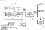
- Fig. 1 is a diagram illustrating a configuration example of a vehicle control system according to a first embodiment.
- a driving curve storage unit 101 outputs a target driving curve when a traveling device 105 causes a train to travel.
- a first driving curve calculation unit 102 and a second driving curve calculation unit 103 acquire, from a traveling device 105 and an on-vehicle storage device 108 mounted on a vehicle (hereinafter referred to as an own vehicle), the current position and speed of the own vehicle, the train weight of the own vehicle, acceleration/deceleration characteristics of the vehicle, and route information, which are information necessary to calculate a driving curve (hereinafter referred to as an energy-saving driving curve) with low energy consumption.
- the remaining traveling time for the target arrival time to the next station is acquired from a time designation unit 106.
- a method of acquiring the current position and speed of the own vehicle may be the method usually provided by a railway vehicle and, for example, it can be realized by a method of calculating the traveling distance and speed of a vehicle from the integration with a wheel system by measuring the number of rotations and angular velocity of the wheels.
- the position of the train may be acquired by a global positioning system (GPS) and the traveling distance and speed of the vehicle may be obtained by the change with time of the position.
- GPS global positioning system
- Route information is information for calculating a consumption energy driving curve and includes, for example, information such as the relationship between the position on the route and the altitude or the speed limit and the gradient.
- the driving curve calculation unit 102 calculates a driving curve satisfying the remaining traveling time with the position and speed at a point where the generation of the energy-saving driving curve is started as a starting point.
- constraints for not exceeding the speed limit are included in the driving curve generation algorithm.
- the train weight, the vehicle acceleration/deceleration characteristics, and the route information acquired from the on-vehicle storage device 108 are used.
- the driving curve calculation unit 102 the time granularity and condition of the energy-saving driving curve generation algorithm are roughly set and the energy-saving driving curve is calculated in a few seconds.
- the generated first driving curve is output to a driving curve joining unit 104 and stored in the driving curve storage unit 101.
- the driving curve calculation unit 103 Similar to the driving curve calculation unit 102, the driving curve calculation unit 103 also calculates a driving curve satisfying the remaining traveling time with the position and speed of the own vehicle at a point where generation of the energy-saving driving curves read from the on-vehicle storage device 108 is started as the starting point.
- the energy-saving driving curve generation algorithm of the driving curve calculation unit 103 is different from that of the driving curve calculation unit 102.
- the time granularity and condition of the energy-saving driving curve generation algorithm are set precisely and the driving curve with the minimum energy consumption is calculated.
- the generated second driving curve is stored in the driving curve joining unit 104.
- the driving curve joining unit 104 searches for a point (reference point) where the speeds match within a specific range at each position of the first driving curve and the second driving curve. This search is started even in the middle of the calculation of the second operating curve. If in the middle of the calculation, the reference point is searched in a section up to the point where the calculation is completed at that time. Then, every time the calculation completion section of the second driving curve increases, this search is sequentially performed.
- the calculation of the second driving curve may start from the end point, which is the point at which the generation of the energy-saving driving curve is finished, and proceed in the direction of the starting point.
- the reference point is searched every time the calculation completion section of the second driving curve increases.
- a point (reference point) at which the speeds matches in a specified range is found, it is possible to complete the generation of the driving curve in the section where the driving curve is generated.
- the calculation of the driving curve further on the end point side than the reference point is not completed and there is no driving curve to be followed by the vehicle.
- the driving curve joining unit 104 calculates a joint driving curve for switching from the first driving curve to the second driving curve after the reference point and outputs the joint driving curve to a driving curve joint determination unit 107.
- the time designation unit 106 outputs the arrival time to the driving curve joint determination unit 107.
- the driving curve joint determination unit 107 determines whether the arrival time output from the time designation unit 106 is satisfied and stores the joint driving curve in the driving curve storage unit 101 if satisfied.
- the driving curve storage unit 101 outputs the stored driving curve to the traveling device 105 and the traveling device 105 instructs the train to travel according to the driving curve.
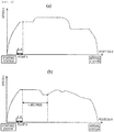
- Fig. 2 is a diagram illustrating a state in which an energy-saving driving curve from a point A to a destination station is generated (a) when the driving curve, the time granularity and condition are roughly calculated and (b) when the driving curve, the time granularity and condition are precisely calculated.
- the driving curve is calculated immediately (in fact, calculating time is sufficiently smaller than the response speed of a drive system of the vehicle, such as about one second) with the rough time granularity and condition, as illustrated in Fig. 2(a)
- the vehicle can be traveled in a state where the position and speed of the vehicle do not deviate from the calculated driving curve .
- the driving curve is calculated with the precise time granularity and condition as illustrated in Fig.
- n seconds which are the time required to generate the driving curve increase. Therefore, although the driving curve after n seconds is precise and the energy saving property is higher than in the case of (a), the possibility that the position and speed of the train deviate from the calculated driving curve at the time of n seconds is increased. As a result, during the n seconds and after n seconds, it takes extra energy to travel during return from the deviation, and thus, compared to the calculation accuracy of the driving curve, the total energy consumption from the departure station to the arrival station may be larger in the case of Fig. 2(b) .
- Fig. 3 is a diagram illustrating a state where the driving curve from the point A to the arrival station is calculated by two calculation units by the method according to the embodiment.
- the first driving curve which is an energy-saving driving curve with roughly calculated time granularity and condition
- the second driving curve which is an energy-saving driving curve with precisely calculated time granularity and condition
- the vehicle travels according to the first driving curve and, among the points (a1 to a3 in the drawing) at which the positions and speeds match in the first and second driving curves, a reference point which can switch a tracking destination of the vehicle from the previous driving curve to the other driving curve is searched, and then, when the reference point is present, the vehicle travels from the position according to the second driving curve. Therefore, the vehicle can travel up to the reference point without deviation from the first driving curve and can travel along the second driving curve which is more energy-saving than the first driving curve beyond the reference point. As a result, the total energy consumption from the departure station to the arrival station can be smaller than when the vehicle follows only one of the first driving curve and the second driving curve.
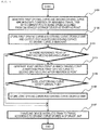
- Fig. 4 is a flowchart illustrating a procedure of processing of a train control system of the embodiment.
- Step S101 The first driving curve calculation unit 102 and the second driving curve calculation unit 103 acquire the current position and speed of the own vehicle, which is information necessary for generating a driving curve, from the traveling device 105 and the on-vehicle storage device 108 and the remaining traveling time to the next station from the time designation unit 106 and start generation of a driving curve satisfying the condition of the remaining traveling time with the current position and speed as the starting point.
- Step S102 First, the first driving curve calculation unit 102 stores the obtained first driving curve in the driving curve storage unit 101 and at the same time outputs the obtained first driving curve to the driving curve joining unit 104.
- the second driving curve calculation unit 103 also outputs the obtained second driving curve to the driving curve joining unit 104 at the time the second driving curve calculation unit 103 calculated part or all of the second driving curve.
- Step S103 The driving curve joining unit 104 determines whether, between the first and second driving curves, there is the reference point where positions and speeds match in a specific range.
- the specific range related to the determination of match refers to the width of a range for allowing calculation errors at least when the process is implemented by a computer. In practical terms, considering the drive characteristics of the vehicle, it is sufficient to be set to allow for a gap of the following target speed at which rapid acceleration or deceleration does not occur such that the ride quality deteriorates.
- Step S103 When a negative result (No) is obtained in the determination of Step S103, the process proceeds to Step S107, and when a positive result (Yes) is obtained, the process proceeds to Step S104.
- Step S104 A joint driving curve is generated by joining the first and second driving curves at the reference point and is output to the driving curve joint determination unit 107.
- Step S105 The driving curve joint determination unit 107 determines whether the input joint driving curve satisfies the arrival time output from the time designation unit.
- Step S105 When a negative result is obtained in the determination of Step S105, the process proceeds to Step S107, and when a positive result is obtained, the driving curve joint determination unit 107 outputs the joint driving curve to the driving curve storage unit 101 and the process proceeds to Step S106.
- Step S106 The driving curve storage unit 101 rewrites, to the joint driving curve, the first driving curve stored in Step S102 in the driving curve storage unit 101.
- Step S107 The traveling device 105 travels the train according to the driving curve stored in the driving curve storage unit 101.
- Step S103 when there is a plurality of reference points in Step S103, among those reference points for which a positive result is obtained by the determination of Step S105 when the processing of Step S104 and the determination of Step S105 are applied to, the reference point located closest to the front side (closer to the vehicle) is used and the process of Step S106 is applied. Therefore, it is possible to secure more sections in which the vehicle travels along the second driving curve, and as a result, it is possible to reduce the energy consumption required for total travel.
- the condition when searching whether there is a joinable position, at each position, the terms that the speeds and the remaining traveling times match within a specific range are used as the condition.
- the condition may be determined by the punctuality required for the train.
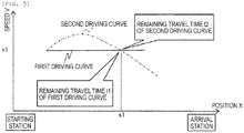
- Fig. 5 is a diagram illustrating a state in which the remaining traveling times do not match at the point where the positions and speeds in the first and second driving curves match.
- the first and second driving curves match with each other at a position X1 and a velocity V1, but the remaining traveling times do not match with t1 and t2 respectively.
- the point is taken as a position where joining can be performed.
- the time that may be delayed may be set as the allowable value.
- the calculation of the first driving curve with the roughly calculated time granularity and the and the calculation of the second driving curve with the precisely calculated time granularity and condition are generated, the vehicle travels according to the first driving curve at first, and the vehicle travels according to the second driving curve from the switchable points when there is a point at which the first and second driving curves can be switched, in such a manner that a train can travel according to the driving curves with low energy consumption.
- a method will be described where a second driving curve with the time granularity and condition precisely calculated considering energy consumption is generated with the position and speed of the reference point in the middle of a first driving curve with the time granularity and condition roughly calculated considering energy consumption as the starting point.
- the same components as those of the first embodiment are denoted by the same reference numerals and the description thereof will be omitted.
- the starting point of the second driving curve is set to the current position and speed of the vehicle.
- the second embodiment differs from the first embodiment in that the starting point of the second driving curve is set to the position and speed of a reference point in the middle of the first driving curve.
- Fig. 6 is a diagram illustrating a state in which the second driving curve is generated with the position and speed (point b) of the reference point in the middle of the first driving curve as a starting point in the method according to the present embodiment.
- the two driving curves can be reliably connected by generating the second driving curve with the certain position and speed of the first driving curve as the starting point.
- Fig. 7 is a diagram illustrating a configuration example of a train control system in the second embodiment.
- a driving curve storage unit 201 outputs a driving curve to be followed when the vehicle travels.
- a first driving curve calculation unit 202 acquires the current position and speed of the own vehicle, which is the information necessary to calculate the driving curve, from a traveling device and an on-vehicle storage device of the own vehicle, the train weight of the own vehicle, acceleration/deceleration characteristics of the vehicle, and route information from the on-vehicle storage device, and the arrival time from a time designation unit 206.
- the remaining traveling time to a next station can be calculated from the difference between the current time and the arrival time.
- the first driving curve calculation unit 202 calculates a driving curve satisfying the remaining traveling time with the position and speed at a point where the generation of the energy-saving driving curve is started as the starting point.
- the time granularity and condition of the energy-saving driving curve generation algorithm are roughly set and the energy-saving driving curve is calculated in a few seconds, and then the generated first driving curve is output to a second driving curve calculation unit 203 and a driving curve joining unit 204 and stored in the driving curve storage unit 201.
- the second driving curve calculation unit 203 generates a second driving curve with the position and speed of the reference point in the middle of the section in the first driving curve output from the first driving curve calculation unit 202 as the starting point.
- the energy-saving driving curve generation algorithm of the second driving curve calculation unit 203 is more precise in setting the time granularity and condition than the algorithm of the first driving curve calculation unit 202.
- the second driving curve calculation unit 203 also stores the generated second driving curve in the driving curve joining unit 204.
- the reference point in the middle of the section is a point at which the vehicle reached at the time the second driving curve calculation unit 203 finishes the calculation of the second driving curve, when the first driving curve calculation unit 202 calculates the first driving curve at first.
- the method of determining the reference point is not limited to here and the embodiment can be implemented when the reference point is a point (end station side) beyond the point determined by the present method.
- the time until the calculation of the second driving curve is finished cannot be precisely estimated considering that the time varies depending on the load condition of a computer, or the like. It is desirable from a practical point of view to set the time a little on the end point side as a margin considering fluctuation.
- the driving curve joining unit 204 calculates a joint driving curve for switching the driving curve from the first driving curve to the second driving curve at the reference point and outputs the joint driving curve to a driving curve joint determination unit 207.
- the time designation unit 206 outputs the arrival time to a driving curve joint determination unit 207.
- the driving curve joint determination unit 207 determines whether the arrival time output from the time designation unit 206 is satisfied when traveling according to the joint driving curve output from the driving curve joining unit 204 and, when arrival time is satisfied, the joint driving curve is stored in the driving curve storage unit 201.
- the driving curve storage unit 201 outputs the stored driving curve to a traveling device 205 and the traveling device 205 travels the train according to the driving curve.
- Fig. 8 is a flowchart illustrating a procedure of processing of the train control system of the embodiment.
- Step S201 The first driving curve calculation unit 202 acquires the current position and speed of the own vehicle, which is information necessary for generating a driving curve, from the traveling device 205 and the on-vehicle storage device and the remaining traveling time to the next station from the time designation unit 206 and generates a first driving curve satisfying the condition of the remaining traveling time with the current position and speed as the starting point.
- Step S202 The first driving curve calculation unit 202 stores the obtained first driving curve in the driving curve storage unit 201 and at the same time outputs the obtained first driving curve to the driving curve joining unit 204 and the second driving curve calculation unit 203.
- Step S203 The second driving curve calculation unit 203 starts generating a second driving curve with the position and speed of the reference point in the middle of the first driving curve as the starting point.
- Step S204 The driving curve joining unit 204 generates a joint driving curve in which the first driving curve is switched to the second driving curve after the reference point and outputs the joint driving curve to the driving curve joint determination unit 207.
- Step S205 The driving curve joint determination unit 207 determines whether the input joint driving curve satisfies the arrival time output from time designation unit.
- Step S205 When a negative result (No) is obtained in the determination of Step S205, the process proceeds to Step S207, and when a positive result (Yes) is obtained, the process proceeds to Step S206.
- Step S206 The driving curve storage unit 201 rewrites the first driving curve stored in the driving curve storage unit 201 in Step S202 to the joint driving curve and stores the first driving curve.
- Step S207 The traveling device 205 instructs the vehicle to travel according to the driving curve stored in the driving curve storage unit 201.
- the train by generating the second driving curve with the position and speed at the reference point in the middle of the first driving curve as the starting point, the train can travel according to the driving curve with less energy consumption by surely switching the driving curve from the first driving curve to the second driving curve.
Landscapes
- Engineering & Computer Science (AREA)
- Mechanical Engineering (AREA)
- Power Engineering (AREA)
- Transportation (AREA)
- Electric Propulsion And Braking For Vehicles (AREA)
Description
- The present invention relates to a vehicle control system for driving a vehicle with less energy.
- When a railway vehicle travels from a certain point to a target point according to a given target travel time, operations such as acceleration, constant speed running, coasting, and braking are performed. However, the relationship between a position and a speed of the vehicle at that time can be represented by a position-speed trajectory called a driving curve. Even when the target travel time is the same, if a driving curve to be followed by the vehicle is different, the energy required for traveling is also different. Therefore, determining a driving curve (energy-saving driving curve) with less energy consumption and controlling the vehicle according to the driving curve are effective for reducing the energy required for traveling.
- There is a delay corresponding to the calculation time and the transmission time until the energy-saving driving curve is calculated and reflected in the vehicle control. When a train travels during this delay time, the calculated energy-saving driving curve will deviate from the actual position and speed of the train. When the train is accelerated or decelerated to follow the diverging driving curve, the energy saving performance and riding comfort will be reduced.
- In order to reduce deviation between the calculated driving curve and the actual driving curve, a method of estimating the position and speed of the train after n seconds and calculating the driving curve after n seconds from the position and speed as a starting point is described in
JP-A-2015-177695 PTL 1, it is described that "In thetraffic management system 1, when the current traveling condition of the train deviates from the target run curve (energy-saving run curve) having the energy saving effect, the on-vehicle device 10 predicts the position and speed of the own train after n seconds and requests the ground device 20 to regenerate the energy-saving run curve from the position and speed of the own train after (for example, after n seconds) a set time has passed. The ground device 20 regenerates the energy-saving run curve from the position and speed of the train after n seconds." -
EP-A-2832581 (PTL 2) proposes a train control device which sets an emergency brake pattern and a regular brake pattern as patterns of maximum speed according to the distance to a stopping point, and outputs a brake command when the train speed exceeds the maximum speed. -
- PTL 1:
JP-A-2015-177695 - PTL 2:
EP-A-2832581 - The generation of an energy-saving driving curve generally involves execution of an algorithm for searching for a minimum energy consumption solution and the search takes time when a minimum energy driving curve is to be determined precisely. Conversely, when the driving curve with less energy consumption is roughly determined, the search can be completed in a short time.
- In other words, when the driving curve with the lowest energy consumption is accurately determined, the energy saving performance in a section where a train can travel can be increased according to the driving curve, but there is a possibility that the position and speed of the train when calculation is completed may deviate from the calculated driving curve. On the other hand, when the driving curve with less energy consumption is determined with less precision, the train can travel according to the determined driving curve, but the energy saving performance is lower than that of the precise solution. The problem is to generate an energy-saving driving curve considering such contradictory problems.
- In order to solve the problems described above, the invention adopts the configuration described in the claims.
- That is, according to the invention, there is provided a vehicle control system according to
claim 1. - According to the invention, there is also provided a vehicle control system according to claim 3.
- According to the invention, there is provided a vehicle control method according to claim 5.
- According to the invention, there is also provided a vehicle control method according to claim 7.
- According to the invention, it is possible to make a vehicle travel according to a driving curve with less energy consumption.
-
- [
Fig. 1] Fig. 1 is a diagram illustrating an example of a functional configuration of a driving curve calculation unit according to a first embodiment. - [
Fig. 2] Fig. 2 is a diagram illustrating an example of a task of n seconds determination in the document of the related art. - [
Fig. 3] Fig. 3 is a diagram illustrating an example of a relationship between a vehicle speed and a position when switching between a first driving curve and a second driving curve in the first embodiment. - [
Fig. 4] Fig. 4 is a flowchart illustrating an example of driving curve generation to be output to a traveling device in the first embodiment. - [
Fig. 5] Fig. 5 is a diagram illustrating an example of a state in which remaining traveling times do not match at a point where positions and speeds in the first and second driving curves match. - [
Fig. 6] Fig. 6 is a diagram illustrating an example of a relationship between a vehicle speed and a position when switching between the first driving curve and the second driving curve in a second embodiment. - [
Fig. 7] Fig. 7 is a diagram illustrating an example of a functional configuration of a driving curve calculation unit in the second embodiment. - [
Fig. 8] Fig. 8 is a flowchart illustrating an example of driving curve determination in the second embodiment. - Hereinafter, embodiments of the present invention will be described based on the drawings.
- In the embodiment, a case will be described where a railway vehicle travels between stations along a driving curve formed by joining two energy-saving driving curves with different precision at a certain point.
-
Fig. 1 is a diagram illustrating a configuration example of a vehicle control system according to a first embodiment. - A driving
curve storage unit 101 outputs a target driving curve when atraveling device 105 causes a train to travel. - A first driving
curve calculation unit 102 and a second drivingcurve calculation unit 103 acquire, from atraveling device 105 and an on-vehicle storage device 108 mounted on a vehicle (hereinafter referred to as an own vehicle), the current position and speed of the own vehicle, the train weight of the own vehicle, acceleration/deceleration characteristics of the vehicle, and route information, which are information necessary to calculate a driving curve (hereinafter referred to as an energy-saving driving curve) with low energy consumption. The remaining traveling time for the target arrival time to the next station is acquired from atime designation unit 106. - Here, a method of acquiring the current position and speed of the own vehicle may be the method usually provided by a railway vehicle and, for example, it can be realized by a method of calculating the traveling distance and speed of a vehicle from the integration with a wheel system by measuring the number of rotations and angular velocity of the wheels. The position of the train may be acquired by a global positioning system (GPS) and the traveling distance and speed of the vehicle may be obtained by the change with time of the position.
- Route information is information for calculating a consumption energy driving curve and includes, for example, information such as the relationship between the position on the route and the altitude or the speed limit and the gradient.
- The driving
curve calculation unit 102 calculates a driving curve satisfying the remaining traveling time with the position and speed at a point where the generation of the energy-saving driving curve is started as a starting point. Here, constraints for not exceeding the speed limit are included in the driving curve generation algorithm. In order to calculate the acceleration/deceleration at the time of power running, constant speed running, coasting, and braking of the vehicle at each position, the train weight, the vehicle acceleration/deceleration characteristics, and the route information acquired from the on-vehicle storage device 108 are used. In the drivingcurve calculation unit 102, the time granularity and condition of the energy-saving driving curve generation algorithm are roughly set and the energy-saving driving curve is calculated in a few seconds. The generated first driving curve is output to a drivingcurve joining unit 104 and stored in the drivingcurve storage unit 101. - Similar to the driving
curve calculation unit 102, the drivingcurve calculation unit 103 also calculates a driving curve satisfying the remaining traveling time with the position and speed of the own vehicle at a point where generation of the energy-saving driving curves read from the on-vehicle storage device 108 is started as the starting point. However, the energy-saving driving curve generation algorithm of the drivingcurve calculation unit 103 is different from that of the drivingcurve calculation unit 102. The time granularity and condition of the energy-saving driving curve generation algorithm are set precisely and the driving curve with the minimum energy consumption is calculated. The generated second driving curve is stored in the drivingcurve joining unit 104. - The driving
curve joining unit 104 searches for a point (reference point) where the speeds match within a specific range at each position of the first driving curve and the second driving curve. This search is started even in the middle of the calculation of the second operating curve. If in the middle of the calculation, the reference point is searched in a section up to the point where the calculation is completed at that time. Then, every time the calculation completion section of the second driving curve increases, this search is sequentially performed. - The calculation of the second driving curve may start from the end point, which is the point at which the generation of the energy-saving driving curve is finished, and proceed in the direction of the starting point. Here, the reference point is searched every time the calculation completion section of the second driving curve increases. However, when a point (reference point) at which the speeds matches in a specified range is found, it is possible to complete the generation of the driving curve in the section where the driving curve is generated. As a result, it is possible to avoid the situation where, although the reference point is found, the calculation of the driving curve further on the end point side than the reference point is not completed and there is no driving curve to be followed by the vehicle. Naturally, it is not necessary to stop the calculation of the second driving curve when one reference point is found and it may be possible to calculate until the calculation reaches the starting point and find a plurality of reference points. Here, by joining the first driving curve and the second driving curve at the closest reference point among the reference points located further on the end point side than the own vehicle, it is possible to secure more sections where the vehicle travels along the second driving curve, and as a result, it is possible to reduce the energy consumption for total travel.
- If there is a reference point, the driving
curve joining unit 104 calculates a joint driving curve for switching from the first driving curve to the second driving curve after the reference point and outputs the joint driving curve to a driving curvejoint determination unit 107. Thetime designation unit 106 outputs the arrival time to the driving curvejoint determination unit 107. When the vehicle travels following the joint driving curve output from the drivingcurve joining unit 104, the driving curvejoint determination unit 107 determines whether the arrival time output from thetime designation unit 106 is satisfied and stores the joint driving curve in the drivingcurve storage unit 101 if satisfied. - The driving
curve storage unit 101 outputs the stored driving curve to the travelingdevice 105 and the travelingdevice 105 instructs the train to travel according to the driving curve. -
Fig. 2 is a diagram illustrating a state in which an energy-saving driving curve from a point A to a destination station is generated (a) when the driving curve, the time granularity and condition are roughly calculated and (b) when the driving curve, the time granularity and condition are precisely calculated. Here, when the driving curve is calculated immediately (in fact, calculating time is sufficiently smaller than the response speed of a drive system of the vehicle, such as about one second) with the rough time granularity and condition, as illustrated inFig. 2(a) , the vehicle can be traveled in a state where the position and speed of the vehicle do not deviate from the calculated driving curve . On the other hand, when the driving curve is calculated with the precise time granularity and condition as illustrated inFig. 2(b) , n seconds which are the time required to generate the driving curve increase. Therefore, although the driving curve after n seconds is precise and the energy saving property is higher than in the case of (a), the possibility that the position and speed of the train deviate from the calculated driving curve at the time of n seconds is increased. As a result, during the n seconds and after n seconds, it takes extra energy to travel during return from the deviation, and thus, compared to the calculation accuracy of the driving curve, the total energy consumption from the departure station to the arrival station may be larger in the case ofFig. 2(b) . -
Fig. 3 is a diagram illustrating a state where the driving curve from the point A to the arrival station is calculated by two calculation units by the method according to the embodiment. In the embodiment, the first driving curve, which is an energy-saving driving curve with roughly calculated time granularity and condition, and the second driving curve, which is an energy-saving driving curve with precisely calculated time granularity and condition, are started to be generated. First, the vehicle travels according to the first driving curve and, among the points (a1 to a3 in the drawing) at which the positions and speeds match in the first and second driving curves, a reference point which can switch a tracking destination of the vehicle from the previous driving curve to the other driving curve is searched, and then, when the reference point is present, the vehicle travels from the position according to the second driving curve. Therefore, the vehicle can travel up to the reference point without deviation from the first driving curve and can travel along the second driving curve which is more energy-saving than the first driving curve beyond the reference point. As a result, the total energy consumption from the departure station to the arrival station can be smaller than when the vehicle follows only one of the first driving curve and the second driving curve. - Next, a flow of the process where, in the vehicle control system of the example, the calculation of the first driving curve and the second driving curve is started, the vehicle travels according to the first driving curve at first and, after the calculation of the second driving curve, the vehicle travels according to the second driving curve from the point where the first and second driving curves can be switched will be described.
-
Fig. 4 is a flowchart illustrating a procedure of processing of a train control system of the embodiment. - Step S101: The first driving
curve calculation unit 102 and the second drivingcurve calculation unit 103 acquire the current position and speed of the own vehicle, which is information necessary for generating a driving curve, from the travelingdevice 105 and the on-vehicle storage device 108 and the remaining traveling time to the next station from thetime designation unit 106 and start generation of a driving curve satisfying the condition of the remaining traveling time with the current position and speed as the starting point. - Step S102: First, the first driving
curve calculation unit 102 stores the obtained first driving curve in the drivingcurve storage unit 101 and at the same time outputs the obtained first driving curve to the drivingcurve joining unit 104. Next, the second drivingcurve calculation unit 103 also outputs the obtained second driving curve to the drivingcurve joining unit 104 at the time the second drivingcurve calculation unit 103 calculated part or all of the second driving curve. - Step S103: The driving
curve joining unit 104 determines whether, between the first and second driving curves, there is the reference point where positions and speeds match in a specific range. Here, the specific range related to the determination of match refers to the width of a range for allowing calculation errors at least when the process is implemented by a computer. In practical terms, considering the drive characteristics of the vehicle, it is sufficient to be set to allow for a gap of the following target speed at which rapid acceleration or deceleration does not occur such that the ride quality deteriorates. - When a negative result (No) is obtained in the determination of Step S103, the process proceeds to Step S107, and when a positive result (Yes) is obtained, the process proceeds to Step S104.
- Step S104: A joint driving curve is generated by joining the first and second driving curves at the reference point and is output to the driving curve
joint determination unit 107. - Step S105: The driving curve
joint determination unit 107 determines whether the input joint driving curve satisfies the arrival time output from the time designation unit. - When a negative result is obtained in the determination of Step S105, the process proceeds to Step S107, and when a positive result is obtained, the driving curve
joint determination unit 107 outputs the joint driving curve to the drivingcurve storage unit 101 and the process proceeds to Step S106. - Step S106: The driving
curve storage unit 101 rewrites, to the joint driving curve, the first driving curve stored in Step S102 in the drivingcurve storage unit 101. - Step S107: The traveling
device 105 travels the train according to the driving curve stored in the drivingcurve storage unit 101. - In the flow of processing, when there is a plurality of reference points in Step S103, among those reference points for which a positive result is obtained by the determination of Step S105 when the processing of Step S104 and the determination of Step S105 are applied to, the reference point located closest to the front side (closer to the vehicle) is used and the process of Step S106 is applied. Therefore, it is possible to secure more sections in which the vehicle travels along the second driving curve, and as a result, it is possible to reduce the energy consumption required for total travel.
- In the driving
curve joining unit 104, when searching whether there is a joinable position, at each position, the terms that the speeds and the remaining traveling times match within a specific range are used as the condition. However, the condition may be determined by the punctuality required for the train. - For example,
Fig. 5 is a diagram illustrating a state in which the remaining traveling times do not match at the point where the positions and speeds in the first and second driving curves match. The first and second driving curves match with each other at a position X1 and a velocity V1, but the remaining traveling times do not match with t1 and t2 respectively. Here, when a difference (t1-t2) second is permitted from the viewpoint of punctuality, the point is taken as a position where joining can be performed. When it is possible to delay the station arrival time of the own vehicle due to the delay of a preceding train, the time that may be delayed may be set as the allowable value. - As described above, according to the embodiment, the calculation of the first driving curve with the roughly calculated time granularity and the and the calculation of the second driving curve with the precisely calculated time granularity and condition are generated, the vehicle travels according to the first driving curve at first, and the vehicle travels according to the second driving curve from the switchable points when there is a point at which the first and second driving curves can be switched, in such a manner that a train can travel according to the driving curves with low energy consumption.
- In the present embodiment, a method will be described where a second driving curve with the time granularity and condition precisely calculated considering energy consumption is generated with the position and speed of the reference point in the middle of a first driving curve with the time granularity and condition roughly calculated considering energy consumption as the starting point. The same components as those of the first embodiment are denoted by the same reference numerals and the description thereof will be omitted.
- In the first embodiment, the starting point of the second driving curve is set to the current position and speed of the vehicle. However, the second embodiment differs from the first embodiment in that the starting point of the second driving curve is set to the position and speed of a reference point in the middle of the first driving curve.
-
Fig. 6 is a diagram illustrating a state in which the second driving curve is generated with the position and speed (point b) of the reference point in the middle of the first driving curve as a starting point in the method according to the present embodiment. In the present embodiment, the two driving curves can be reliably connected by generating the second driving curve with the certain position and speed of the first driving curve as the starting point. -
Fig. 7 is a diagram illustrating a configuration example of a train control system in the second embodiment. - A driving
curve storage unit 201 outputs a driving curve to be followed when the vehicle travels. - Similar to that of the first embodiment, a first driving
curve calculation unit 202 acquires the current position and speed of the own vehicle, which is the information necessary to calculate the driving curve, from a traveling device and an on-vehicle storage device of the own vehicle, the train weight of the own vehicle, acceleration/deceleration characteristics of the vehicle, and route information from the on-vehicle storage device, and the arrival time from atime designation unit 206. The remaining traveling time to a next station can be calculated from the difference between the current time and the arrival time. - The first driving
curve calculation unit 202 calculates a driving curve satisfying the remaining traveling time with the position and speed at a point where the generation of the energy-saving driving curve is started as the starting point. In the first drivingcurve calculation unit 202, the time granularity and condition of the energy-saving driving curve generation algorithm are roughly set and the energy-saving driving curve is calculated in a few seconds, and then the generated first driving curve is output to a second drivingcurve calculation unit 203 and a drivingcurve joining unit 204 and stored in the drivingcurve storage unit 201. - The second driving
curve calculation unit 203 generates a second driving curve with the position and speed of the reference point in the middle of the section in the first driving curve output from the first drivingcurve calculation unit 202 as the starting point. The energy-saving driving curve generation algorithm of the second drivingcurve calculation unit 203 is more precise in setting the time granularity and condition than the algorithm of the first drivingcurve calculation unit 202. The second drivingcurve calculation unit 203 also stores the generated second driving curve in the drivingcurve joining unit 204. - Here, the reference point in the middle of the section is a point at which the vehicle reached at the time the second driving
curve calculation unit 203 finishes the calculation of the second driving curve, when the first drivingcurve calculation unit 202 calculates the first driving curve at first. The method of determining the reference point is not limited to here and the embodiment can be implemented when the reference point is a point (end station side) beyond the point determined by the present method. The time until the calculation of the second driving curve is finished cannot be precisely estimated considering that the time varies depending on the load condition of a computer, or the like. It is desirable from a practical point of view to set the time a little on the end point side as a margin considering fluctuation. - The driving
curve joining unit 204 calculates a joint driving curve for switching the driving curve from the first driving curve to the second driving curve at the reference point and outputs the joint driving curve to a driving curvejoint determination unit 207. Thetime designation unit 206 outputs the arrival time to a driving curvejoint determination unit 207. The driving curvejoint determination unit 207 determines whether the arrival time output from thetime designation unit 206 is satisfied when traveling according to the joint driving curve output from the drivingcurve joining unit 204 and, when arrival time is satisfied, the joint driving curve is stored in the drivingcurve storage unit 201. - The driving
curve storage unit 201 outputs the stored driving curve to a travelingdevice 205 and the travelingdevice 205 travels the train according to the driving curve. -
Fig. 8 is a flowchart illustrating a procedure of processing of the train control system of the embodiment. - Step S201: The first driving
curve calculation unit 202 acquires the current position and speed of the own vehicle, which is information necessary for generating a driving curve, from the travelingdevice 205 and the on-vehicle storage device and the remaining traveling time to the next station from thetime designation unit 206 and generates a first driving curve satisfying the condition of the remaining traveling time with the current position and speed as the starting point. - Step S202: The first driving
curve calculation unit 202 stores the obtained first driving curve in the drivingcurve storage unit 201 and at the same time outputs the obtained first driving curve to the drivingcurve joining unit 204 and the second drivingcurve calculation unit 203. - Step S203: The second driving
curve calculation unit 203 starts generating a second driving curve with the position and speed of the reference point in the middle of the first driving curve as the starting point. - Step S204: The driving
curve joining unit 204 generates a joint driving curve in which the first driving curve is switched to the second driving curve after the reference point and outputs the joint driving curve to the driving curvejoint determination unit 207. - Step S205: The driving curve
joint determination unit 207 determines whether the input joint driving curve satisfies the arrival time output from time designation unit. - When a negative result (No) is obtained in the determination of Step S205, the process proceeds to Step S207, and when a positive result (Yes) is obtained, the process proceeds to Step S206.
- Step S206: The driving
curve storage unit 201 rewrites the first driving curve stored in the drivingcurve storage unit 201 in Step S202 to the joint driving curve and stores the first driving curve. - Step S207: The traveling
device 205 instructs the vehicle to travel according to the driving curve stored in the drivingcurve storage unit 201. - As described above, according to the second embodiment, by generating the second driving curve with the position and speed at the reference point in the middle of the first driving curve as the starting point, the train can travel according to the driving curve with less energy consumption by surely switching the driving curve from the first driving curve to the second driving curve.
-
- 101:
- vehicle curve storage unit
- 102:
- first driving curve calculation unit
- 103:
- second driving curve calculation unit
- 104:
- driving curve joining unit
- 105:
- traveling device
- 106:
- time designation unit
- 107:
- driving curve joint determination unit
- 108:
- on-vehicle storage device
- 201:
- vehicle curve storage unit
- 202:
- first driving curve calculation unit
- 203:
- second driving curve calculation unit
- 204:
- driving curve joining unit
- 205:
- traveling device
- 206:
- time designation unit
- 207:
- driving curve joint determination unit
- 208:
- on-vehicle storage device
Claims (7)
- A vehicle control system, comprising:a driving curve storage unit (101) which is configured to store a driving curve representing a position and speed relationship in a section on a predetermined orbit;a traveling device (105) which is configured to instruct a vehicle to travel the section according to the driving curve read out from the driving curve storage unit;a time designation unit (106) which is configured to define time when the vehicle arrives at an end point of the section;a first driving curve calculation unit (102) which is configured to calculate a driving curve of the section and to store the driving curve into the driving curve storage unit; anda second driving curve calculation unit (103) which is also configured to calculate a driving curve of the section,characterized in that:the driving curve of the section is calculated by the second driving curve calculation unit at a finer time granularity and to provide a higher energy saving compared to the driving curve of the section calculated by the first driving curve calculation unit;and in that the vehicle control system further comprises:a driving curve joining unit (104) which is configured to search for a reference point at which positions and speeds match within a specific range determined in advance between the driving curve calculated by the first driving curve calculation unit and the driving curve calculated by the second driving curve calculation unit and to generate a joint driving curve obtained by joining both driving curves at the reference point when the reference point is found; anda driving curve joint determination unit (107) which is configured to determine whether the time determined by the time designation unit is satisfied when the vehicle travels the section according to the joint driving curve and to store the joint driving curve into the driving curve storage unit when it is determined that the time is satisfied.
- The vehicle control system according to claim 1, wherein
the second driving curve calculation unit is configured to calculate the driving curve in a direction from the end point of the section toward a starting point of the section. - A vehicle control system, comprising:a driving curve storage unit (201) which is configured to store a driving curve representing a position and speed relationship in a section on a predetermined orbit;a traveling device (205) which is configured to instruct a vehicle to travel the section according to the driving curve read out from the driving curve storage unit;a time designation unit (206) which is configured to define time when the vehicle arrives at an end point of the section;a first driving curve calculation unit (202) which is configured to calculate a driving curve including a starting point of the section and a reference point in the middle and to store the driving curve into the driving curve storage unit; anda second driving curve calculation unit (203) which is also configured to calculate a driving curve ,characterized in that:the driving curve is calculated by the second driving curve calculation unit at a finer time granularity and to provide a higher energy saving compared to the driving curve calculated by the first driving curve calculation unit; andthe driving curve is calculated by the second driving curve calculation unit to satisfy a speed at the reference point of the driving curve calculated by the first driving curve calculation unit at the reference point and to include the end point of the section; andin that the vehicle control system further comprises:a driving curve joining unit (204) which is configured to generate a joint driving curve obtained by joining the driving curve calculated by the first driving curve calculation unit and the driving curve calculated by the second driving curve calculation unit at the reference point; anda driving curve joint determination unit (207) which is configured to determine whether the time determined by the time designation unit is satisfied when the vehicle travels the section according to the joint driving curve and to store the joint driving curve into the driving curve storage unit when it is determined that the time is satisfied.
- A vehicle which is mounted with the vehicle control system according to any one of claims 1 to 3.
- A vehicle control method to be executed ina vehicle control system,the vehicle control system including:a driving curve storage unit (101) which is configured to store a driving curve representing a position and speed relationship in a section on a predetermined orbit;a traveling device (105) which is configured to instruct a vehicle to travel the section according to the driving curve read out from the driving curve storage unit;a time designation unit (106) which is configured todefines time when the vehicle arrives at an end point of the section;a first driving curve calculation unit (102) which is configured to calculate a driving curve of the section and to store the driving curve into the driving curve storage unit; anda second driving curve calculation unit (103) which is also configured to calculate a driving curve of the section,characterized in that:the driving curve of the section is calculated by the second driving curve calculation unit at a finer time granularity and to provide a higher energy saving compared to the driving curve of the section calculated by the first driving curve calculation unitand in that the method comprises:searching for a reference point at which positions and speeds match within a specific range determined in advance between the driving curve calculated by the first driving curve calculation unit and the driving curve calculated by the second driving curve calculation unit;generating a joint driving curve obtained by joining both driving curves at the reference point when the reference point is found;determining whether the time determined by the time designation unit is satisfied when the vehicle travels the section according to the joint driving curve; andstoring the joint driving curve into the driving curve storage unit when it is determined that the time is satisfied.
- The vehicle control method according to claim 5, wherein
the second driving curve calculation unit calculates the driving curve in a direction from the end point of the section toward a starting point of the section. - A vehicle control method to be executed ina vehicle control systemthe vehicle control system including:a driving curve storage unit (201) which is configured to store a driving curve representing a position and speed relationship in a section on a predetermined orbit;a traveling device (205) which is configured to instruct a vehicle to travel the section according to the driving curve read out from the driving curve storage unit;a time designation unit (206) which is configured to define time when the vehicle arrives at an end point of the section;a first driving curve calculation unit (202) which is configured to calculate a driving curve including a starting point of the section and a reference point in the middle and to store the driving curve into the driving curve storage unit; anda second driving curve calculation unit (203) which is configured to calculate a driving curve,characterized in that:the driving curve is calculated by the second driving curve calculation unit at a finer time granularity and to provide a higher energy saving compared to the driving curve calculated by the first driving curve calculation unit; andthe driving curve is calculated by the second driving curve calculation unit to satisfy a speed at the reference point of the driving curve calculated by the first driving curve calculation unit at the reference point and to include the end point of the section; andin that the method comprises:generating a joint driving curve obtained by joining the driving curve calculated by the first driving curve calculation unit and the driving curve calculated by the second driving curve calculation unit at the reference point;determining whether the time determined by the time designation unit is satisfied when the vehicle travels the section according to the joint driving curve; andstoring the joint driving curve into the driving curve storage unit when it is determined that the time is satisfied.
Applications Claiming Priority (2)
| Application Number | Priority Date | Filing Date | Title |
|---|---|---|---|
| JP2017031664A JP6707041B2 (en) | 2017-02-23 | 2017-02-23 | Vehicle control system, method and vehicle |
| PCT/JP2017/046046 WO2018154951A1 (en) | 2017-02-23 | 2017-12-21 | Vehicle control system, method and vehicle |
Publications (3)
| Publication Number | Publication Date |
|---|---|
| EP3587168A1 EP3587168A1 (en) | 2020-01-01 |
| EP3587168A4 EP3587168A4 (en) | 2020-12-30 |
| EP3587168B1 true EP3587168B1 (en) | 2021-11-10 |
Family
ID=63253621
Family Applications (1)
| Application Number | Title | Priority Date | Filing Date |
|---|---|---|---|
| EP17897776.5A Active EP3587168B1 (en) | 2017-02-23 | 2017-12-21 | Vehicle control system, method and vehicle |
Country Status (3)
| Country | Link |
|---|---|
| EP (1) | EP3587168B1 (en) |
| JP (1) | JP6707041B2 (en) |
| WO (1) | WO2018154951A1 (en) |
Families Citing this family (2)
| Publication number | Priority date | Publication date | Assignee | Title |
|---|---|---|---|---|
| CN112776835B (en) * | 2021-01-28 | 2022-03-22 | 株洲中车时代电气股份有限公司 | Method and system for controlling automatic trailer of locomotive |
| CN114987576B (en) * | 2022-06-20 | 2024-07-02 | 卡斯柯信号有限公司 | Method for generating braking curve by ITCS train control system |
Family Cites Families (9)
| Publication number | Priority date | Publication date | Assignee | Title |
|---|---|---|---|---|
| JPH07132828A (en) * | 1993-11-11 | 1995-05-23 | Hitachi Ltd | Simulation system |
| KR101079903B1 (en) * | 2009-08-24 | 2011-11-04 | 엘에스산전 주식회사 | Apparatus and method for controlling speed in Automatic Train Operation |
| JP5847596B2 (en) * | 2012-01-16 | 2016-01-27 | 株式会社東芝 | Vehicle travel control device and vehicle travel support device |
| JP5859365B2 (en) * | 2012-03-30 | 2016-02-10 | 日本信号株式会社 | Train control device |
| US8660723B2 (en) * | 2012-06-29 | 2014-02-25 | Mitsubishi Electric Research Laboratories, Inc. | Method for determining run-curves for vehicles in real-time subject to dynamic travel time and speed limit constraint |
| JP6296716B2 (en) * | 2013-07-19 | 2018-03-20 | 株式会社東芝 | Operation curve creation device, control method and control program for operation curve creation device |
| JP6215032B2 (en) * | 2013-12-17 | 2017-10-18 | 株式会社東芝 | Operation plan creation device |
| JP6087805B2 (en) * | 2013-12-26 | 2017-03-01 | 株式会社東芝 | Driving curve making device, driving support device, driving control device and driving curve making method |
| JP6289187B2 (en) * | 2014-03-17 | 2018-03-07 | 三菱電機株式会社 | Train operation control system, on-board device, and train operation control method |
-
2017
- 2017-02-23 JP JP2017031664A patent/JP6707041B2/en active Active
- 2017-12-21 EP EP17897776.5A patent/EP3587168B1/en active Active
- 2017-12-21 WO PCT/JP2017/046046 patent/WO2018154951A1/en not_active Ceased
Also Published As
| Publication number | Publication date |
|---|---|
| JP2018137930A (en) | 2018-08-30 |
| EP3587168A4 (en) | 2020-12-30 |
| WO2018154951A1 (en) | 2018-08-30 |
| JP6707041B2 (en) | 2020-06-10 |
| EP3587168A1 (en) | 2020-01-01 |
Similar Documents
| Publication | Publication Date | Title |
|---|---|---|
| CN106740868B (en) | A kind of method, apparatus and equipment of speed planning | |
| CN110979327A (en) | Longitudinal control method and system for automatic driving vehicle | |
| US9352740B2 (en) | Vehicle energy-management device for controlling energy consumption along a travel route | |
| WO2018121691A1 (en) | Train automatic control method and apparatus, and vehicle-mounted automatic train operation system | |
| JP4793886B2 (en) | Vehicle travel control method | |
| WO2014003151A2 (en) | Method for determining an optimal run-curve for a vehicle | |
| US20230019462A1 (en) | MPC-Based Trajectory Tracking of a First Vehicle Using Trajectory Information on a Second Vehicle | |
| CN114599564B (en) | Determining a trajectory of a first vehicle taking into account the driving behavior of a second vehicle | |
| JP5041071B2 (en) | Vehicle group control method and vehicle | |
| CN114115215B (en) | Platoon driving control method and system | |
| US20140005876A1 (en) | Method for Determining Run-Curves for Vehicles Based on Travel Time | |
| JP5716336B2 (en) | Vehicle group traveling control device, program, and vehicle group traffic flow control system | |
| EP3587168B1 (en) | Vehicle control system, method and vehicle | |
| JP3919553B2 (en) | Automatic train driving device | |
| WO2022130842A1 (en) | Vehicle motion control device and vehicle motion control method | |
| CN101607559A (en) | A kind of method of searching train traction calculation operation curve and device | |
| US11364909B2 (en) | Vehicle control device | |
| US20170210405A1 (en) | Train control device | |
| JP2006006030A (en) | Driving pattern creation device, vehicle speed control device, and vehicle driving support device. | |
| KR101394146B1 (en) | Method for speed control in curved road | |
| JP6599775B2 (en) | Train storage battery control device, method and program | |
| US10030983B2 (en) | Support point management system, method, and program | |
| CN115476898B (en) | Magnetic levitation line operation and control partition dividing method | |
| EP4350663B1 (en) | Vehicle motion control device and vehicle motion control method | |
| JP6802091B2 (en) | Train control system, train control method and on-board equipment of train |
Legal Events
| Date | Code | Title | Description |
|---|---|---|---|
| STAA | Information on the status of an ep patent application or granted ep patent |
Free format text: STATUS: THE INTERNATIONAL PUBLICATION HAS BEEN MADE |
|
| PUAI | Public reference made under article 153(3) epc to a published international application that has entered the european phase |
Free format text: ORIGINAL CODE: 0009012 |
|
| STAA | Information on the status of an ep patent application or granted ep patent |
Free format text: STATUS: REQUEST FOR EXAMINATION WAS MADE |
|
| 17P | Request for examination filed |
Effective date: 20190820 |
|
| AK | Designated contracting states |
Kind code of ref document: A1 Designated state(s): AL AT BE BG CH CY CZ DE DK EE ES FI FR GB GR HR HU IE IS IT LI LT LU LV MC MK MT NL NO PL PT RO RS SE SI SK SM TR |
|
| AX | Request for extension of the european patent |
Extension state: BA ME |
|
| DAV | Request for validation of the european patent (deleted) | ||
| DAX | Request for extension of the european patent (deleted) | ||
| A4 | Supplementary search report drawn up and despatched |
Effective date: 20201201 |
|
| RIC1 | Information provided on ipc code assigned before grant |
Ipc: B61L 27/00 20060101ALI20201125BHEP Ipc: B61L 3/00 20060101ALI20201125BHEP Ipc: B61C 17/12 20060101ALI20201125BHEP Ipc: B61L 25/02 20060101ALI20201125BHEP Ipc: B61L 27/04 20060101ALI20201125BHEP Ipc: B60L 15/40 20060101AFI20201125BHEP Ipc: B60L 15/38 20060101ALI20201125BHEP Ipc: G06F 17/11 20060101ALI20201125BHEP Ipc: B60L 15/20 20060101ALI20201125BHEP |
|
| GRAP | Despatch of communication of intention to grant a patent |
Free format text: ORIGINAL CODE: EPIDOSNIGR1 |
|
| RIC1 | Information provided on ipc code assigned before grant |
Ipc: B60L 15/40 20060101AFI20210503BHEP Ipc: B60L 15/38 20060101ALI20210503BHEP Ipc: B60L 15/20 20060101ALI20210503BHEP Ipc: B61L 15/00 20060101ALI20210503BHEP Ipc: B61L 3/00 20060101ALI20210503BHEP Ipc: B61L 25/02 20060101ALI20210503BHEP Ipc: B61L 27/04 20060101ALI20210503BHEP Ipc: G06F 17/11 20060101ALI20210503BHEP Ipc: B61C 17/12 20060101ALI20210503BHEP Ipc: B61L 27/00 20060101ALI20210503BHEP |
|
| STAA | Information on the status of an ep patent application or granted ep patent |
Free format text: STATUS: GRANT OF PATENT IS INTENDED |
|
| INTG | Intention to grant announced |
Effective date: 20210610 |
|
| GRAS | Grant fee paid |
Free format text: ORIGINAL CODE: EPIDOSNIGR3 |
|
| GRAA | (expected) grant |
Free format text: ORIGINAL CODE: 0009210 |
|
| STAA | Information on the status of an ep patent application or granted ep patent |
Free format text: STATUS: THE PATENT HAS BEEN GRANTED |
|
| AK | Designated contracting states |
Kind code of ref document: B1 Designated state(s): AL AT BE BG CH CY CZ DE DK EE ES FI FR GB GR HR HU IE IS IT LI LT LU LV MC MK MT NL NO PL PT RO RS SE SI SK SM TR |
|
| REG | Reference to a national code |
Ref country code: GB Ref legal event code: FG4D |
|
| REG | Reference to a national code |
Ref country code: AT Ref legal event code: REF Ref document number: 1445780 Country of ref document: AT Kind code of ref document: T Effective date: 20211115 Ref country code: CH Ref legal event code: EP |
|
| REG | Reference to a national code |
Ref country code: DE Ref legal event code: R096 Ref document number: 602017049287 Country of ref document: DE |
|
| REG | Reference to a national code |
Ref country code: IE Ref legal event code: FG4D |
|
| REG | Reference to a national code |
Ref country code: LT Ref legal event code: MG9D |
|
| REG | Reference to a national code |
Ref country code: NL Ref legal event code: MP Effective date: 20211110 |
|
| REG | Reference to a national code |
Ref country code: AT Ref legal event code: MK05 Ref document number: 1445780 Country of ref document: AT Kind code of ref document: T Effective date: 20211110 |
|
| PG25 | Lapsed in a contracting state [announced via postgrant information from national office to epo] |
Ref country code: RS Free format text: LAPSE BECAUSE OF FAILURE TO SUBMIT A TRANSLATION OF THE DESCRIPTION OR TO PAY THE FEE WITHIN THE PRESCRIBED TIME-LIMIT Effective date: 20211110 Ref country code: LT Free format text: LAPSE BECAUSE OF FAILURE TO SUBMIT A TRANSLATION OF THE DESCRIPTION OR TO PAY THE FEE WITHIN THE PRESCRIBED TIME-LIMIT Effective date: 20211110 Ref country code: FI Free format text: LAPSE BECAUSE OF FAILURE TO SUBMIT A TRANSLATION OF THE DESCRIPTION OR TO PAY THE FEE WITHIN THE PRESCRIBED TIME-LIMIT Effective date: 20211110 Ref country code: BG Free format text: LAPSE BECAUSE OF FAILURE TO SUBMIT A TRANSLATION OF THE DESCRIPTION OR TO PAY THE FEE WITHIN THE PRESCRIBED TIME-LIMIT Effective date: 20220210 Ref country code: AT Free format text: LAPSE BECAUSE OF FAILURE TO SUBMIT A TRANSLATION OF THE DESCRIPTION OR TO PAY THE FEE WITHIN THE PRESCRIBED TIME-LIMIT Effective date: 20211110 |
|
| PG25 | Lapsed in a contracting state [announced via postgrant information from national office to epo] |
Ref country code: IS Free format text: LAPSE BECAUSE OF FAILURE TO SUBMIT A TRANSLATION OF THE DESCRIPTION OR TO PAY THE FEE WITHIN THE PRESCRIBED TIME-LIMIT Effective date: 20220310 Ref country code: SE Free format text: LAPSE BECAUSE OF FAILURE TO SUBMIT A TRANSLATION OF THE DESCRIPTION OR TO PAY THE FEE WITHIN THE PRESCRIBED TIME-LIMIT Effective date: 20211110 Ref country code: PT Free format text: LAPSE BECAUSE OF FAILURE TO SUBMIT A TRANSLATION OF THE DESCRIPTION OR TO PAY THE FEE WITHIN THE PRESCRIBED TIME-LIMIT Effective date: 20220310 Ref country code: PL Free format text: LAPSE BECAUSE OF FAILURE TO SUBMIT A TRANSLATION OF THE DESCRIPTION OR TO PAY THE FEE WITHIN THE PRESCRIBED TIME-LIMIT Effective date: 20211110 Ref country code: NO Free format text: LAPSE BECAUSE OF FAILURE TO SUBMIT A TRANSLATION OF THE DESCRIPTION OR TO PAY THE FEE WITHIN THE PRESCRIBED TIME-LIMIT Effective date: 20220210 Ref country code: NL Free format text: LAPSE BECAUSE OF FAILURE TO SUBMIT A TRANSLATION OF THE DESCRIPTION OR TO PAY THE FEE WITHIN THE PRESCRIBED TIME-LIMIT Effective date: 20211110 Ref country code: LV Free format text: LAPSE BECAUSE OF FAILURE TO SUBMIT A TRANSLATION OF THE DESCRIPTION OR TO PAY THE FEE WITHIN THE PRESCRIBED TIME-LIMIT Effective date: 20211110 Ref country code: HR Free format text: LAPSE BECAUSE OF FAILURE TO SUBMIT A TRANSLATION OF THE DESCRIPTION OR TO PAY THE FEE WITHIN THE PRESCRIBED TIME-LIMIT Effective date: 20211110 Ref country code: GR Free format text: LAPSE BECAUSE OF FAILURE TO SUBMIT A TRANSLATION OF THE DESCRIPTION OR TO PAY THE FEE WITHIN THE PRESCRIBED TIME-LIMIT Effective date: 20220211 Ref country code: ES Free format text: LAPSE BECAUSE OF FAILURE TO SUBMIT A TRANSLATION OF THE DESCRIPTION OR TO PAY THE FEE WITHIN THE PRESCRIBED TIME-LIMIT Effective date: 20211110 |
|
| PG25 | Lapsed in a contracting state [announced via postgrant information from national office to epo] |
Ref country code: SM Free format text: LAPSE BECAUSE OF FAILURE TO SUBMIT A TRANSLATION OF THE DESCRIPTION OR TO PAY THE FEE WITHIN THE PRESCRIBED TIME-LIMIT Effective date: 20211110 Ref country code: SK Free format text: LAPSE BECAUSE OF FAILURE TO SUBMIT A TRANSLATION OF THE DESCRIPTION OR TO PAY THE FEE WITHIN THE PRESCRIBED TIME-LIMIT Effective date: 20211110 Ref country code: RO Free format text: LAPSE BECAUSE OF FAILURE TO SUBMIT A TRANSLATION OF THE DESCRIPTION OR TO PAY THE FEE WITHIN THE PRESCRIBED TIME-LIMIT Effective date: 20211110 Ref country code: EE Free format text: LAPSE BECAUSE OF FAILURE TO SUBMIT A TRANSLATION OF THE DESCRIPTION OR TO PAY THE FEE WITHIN THE PRESCRIBED TIME-LIMIT Effective date: 20211110 Ref country code: DK Free format text: LAPSE BECAUSE OF FAILURE TO SUBMIT A TRANSLATION OF THE DESCRIPTION OR TO PAY THE FEE WITHIN THE PRESCRIBED TIME-LIMIT Effective date: 20211110 Ref country code: CZ Free format text: LAPSE BECAUSE OF FAILURE TO SUBMIT A TRANSLATION OF THE DESCRIPTION OR TO PAY THE FEE WITHIN THE PRESCRIBED TIME-LIMIT Effective date: 20211110 |
|
| REG | Reference to a national code |
Ref country code: CH Ref legal event code: PL |
|
| REG | Reference to a national code |
Ref country code: DE Ref legal event code: R097 Ref document number: 602017049287 Country of ref document: DE |
|
| PG25 | Lapsed in a contracting state [announced via postgrant information from national office to epo] |
Ref country code: MC Free format text: LAPSE BECAUSE OF FAILURE TO SUBMIT A TRANSLATION OF THE DESCRIPTION OR TO PAY THE FEE WITHIN THE PRESCRIBED TIME-LIMIT Effective date: 20211110 |
|
| PLBE | No opposition filed within time limit |
Free format text: ORIGINAL CODE: 0009261 |
|
| STAA | Information on the status of an ep patent application or granted ep patent |
Free format text: STATUS: NO OPPOSITION FILED WITHIN TIME LIMIT |
|
| REG | Reference to a national code |
Ref country code: BE Ref legal event code: MM Effective date: 20211231 |
|
| 26N | No opposition filed |
Effective date: 20220811 |
|
| PG25 | Lapsed in a contracting state [announced via postgrant information from national office to epo] |
Ref country code: LU Free format text: LAPSE BECAUSE OF NON-PAYMENT OF DUE FEES Effective date: 20211221 Ref country code: AL Free format text: LAPSE BECAUSE OF FAILURE TO SUBMIT A TRANSLATION OF THE DESCRIPTION OR TO PAY THE FEE WITHIN THE PRESCRIBED TIME-LIMIT Effective date: 20211110 Ref country code: IE Free format text: LAPSE BECAUSE OF NON-PAYMENT OF DUE FEES Effective date: 20211221 |
|
| PG25 | Lapsed in a contracting state [announced via postgrant information from national office to epo] |
Ref country code: SI Free format text: LAPSE BECAUSE OF FAILURE TO SUBMIT A TRANSLATION OF THE DESCRIPTION OR TO PAY THE FEE WITHIN THE PRESCRIBED TIME-LIMIT Effective date: 20211110 Ref country code: FR Free format text: LAPSE BECAUSE OF NON-PAYMENT OF DUE FEES Effective date: 20220110 Ref country code: BE Free format text: LAPSE BECAUSE OF NON-PAYMENT OF DUE FEES Effective date: 20211231 |
|
| PG25 | Lapsed in a contracting state [announced via postgrant information from national office to epo] |
Ref country code: LI Free format text: LAPSE BECAUSE OF NON-PAYMENT OF DUE FEES Effective date: 20211231 Ref country code: CH Free format text: LAPSE BECAUSE OF NON-PAYMENT OF DUE FEES Effective date: 20211231 |
|
| PG25 | Lapsed in a contracting state [announced via postgrant information from national office to epo] |
Ref country code: CY Free format text: LAPSE BECAUSE OF FAILURE TO SUBMIT A TRANSLATION OF THE DESCRIPTION OR TO PAY THE FEE WITHIN THE PRESCRIBED TIME-LIMIT Effective date: 20211110 |
|
| PG25 | Lapsed in a contracting state [announced via postgrant information from national office to epo] |
Ref country code: HU Free format text: LAPSE BECAUSE OF FAILURE TO SUBMIT A TRANSLATION OF THE DESCRIPTION OR TO PAY THE FEE WITHIN THE PRESCRIBED TIME-LIMIT; INVALID AB INITIO Effective date: 20171221 |
|
| PG25 | Lapsed in a contracting state [announced via postgrant information from national office to epo] |
Ref country code: MK Free format text: LAPSE BECAUSE OF FAILURE TO SUBMIT A TRANSLATION OF THE DESCRIPTION OR TO PAY THE FEE WITHIN THE PRESCRIBED TIME-LIMIT Effective date: 20211110 |
|
| PG25 | Lapsed in a contracting state [announced via postgrant information from national office to epo] |
Ref country code: MT Free format text: LAPSE BECAUSE OF FAILURE TO SUBMIT A TRANSLATION OF THE DESCRIPTION OR TO PAY THE FEE WITHIN THE PRESCRIBED TIME-LIMIT Effective date: 20211110 |
|
| PG25 | Lapsed in a contracting state [announced via postgrant information from national office to epo] |
Ref country code: TR Free format text: LAPSE BECAUSE OF FAILURE TO SUBMIT A TRANSLATION OF THE DESCRIPTION OR TO PAY THE FEE WITHIN THE PRESCRIBED TIME-LIMIT Effective date: 20211110 |
|
| PGFP | Annual fee paid to national office [announced via postgrant information from national office to epo] |
Ref country code: DE Payment date: 20251126 Year of fee payment: 9 |
|
| PGFP | Annual fee paid to national office [announced via postgrant information from national office to epo] |
Ref country code: GB Payment date: 20251119 Year of fee payment: 9 |
|
| PGFP | Annual fee paid to national office [announced via postgrant information from national office to epo] |
Ref country code: IT Payment date: 20251119 Year of fee payment: 9 |