EP3587155A1 - Vehicle side structure and vehicle - Google Patents
Vehicle side structure and vehicle Download PDFInfo
- Publication number
- EP3587155A1 EP3587155A1 EP19180517.5A EP19180517A EP3587155A1 EP 3587155 A1 EP3587155 A1 EP 3587155A1 EP 19180517 A EP19180517 A EP 19180517A EP 3587155 A1 EP3587155 A1 EP 3587155A1
- Authority
- EP
- European Patent Office
- Prior art keywords
- door
- engaging pin
- vehicle
- engaging
- receiving portion
- Prior art date
- Legal status (The legal status is an assumption and is not a legal conclusion. Google has not performed a legal analysis and makes no representation as to the accuracy of the status listed.)
- Withdrawn
Links
Images



Classifications
-
- E—FIXED CONSTRUCTIONS
- E05—LOCKS; KEYS; WINDOW OR DOOR FITTINGS; SAFES
- E05B—LOCKS; ACCESSORIES THEREFOR; HANDCUFFS
- E05B77/00—Vehicle locks characterised by special functions or purposes
- E05B77/02—Vehicle locks characterised by special functions or purposes for accident situations
-
- B—PERFORMING OPERATIONS; TRANSPORTING
- B60—VEHICLES IN GENERAL
- B60J—WINDOWS, WINDSCREENS, NON-FIXED ROOFS, DOORS, OR SIMILAR DEVICES FOR VEHICLES; REMOVABLE EXTERNAL PROTECTIVE COVERINGS SPECIALLY ADAPTED FOR VEHICLES
- B60J5/00—Doors
- B60J5/04—Doors arranged at the vehicle sides
- B60J5/042—Reinforcement elements
- B60J5/0422—Elongated type elements, e.g. beams, cables, belts or wires
- B60J5/0423—Elongated type elements, e.g. beams, cables, belts or wires characterised by position in the lower door structure
- B60J5/0427—Elongated type elements, e.g. beams, cables, belts or wires characterised by position in the lower door structure the elements being arranged along the lower edge of door
-
- B—PERFORMING OPERATIONS; TRANSPORTING
- B60—VEHICLES IN GENERAL
- B60J—WINDOWS, WINDSCREENS, NON-FIXED ROOFS, DOORS, OR SIMILAR DEVICES FOR VEHICLES; REMOVABLE EXTERNAL PROTECTIVE COVERINGS SPECIALLY ADAPTED FOR VEHICLES
- B60J5/00—Doors
- B60J5/04—Doors arranged at the vehicle sides
- B60J5/042—Reinforcement elements
- B60J5/0456—Behaviour during impact
- B60J5/0458—Passive coupling of the reinforcement elements to the door or to the vehicle body
-
- B—PERFORMING OPERATIONS; TRANSPORTING
- B60—VEHICLES IN GENERAL
- B60J—WINDOWS, WINDSCREENS, NON-FIXED ROOFS, DOORS, OR SIMILAR DEVICES FOR VEHICLES; REMOVABLE EXTERNAL PROTECTIVE COVERINGS SPECIALLY ADAPTED FOR VEHICLES
- B60J5/00—Doors
- B60J5/04—Doors arranged at the vehicle sides
- B60J5/047—Doors arranged at the vehicle sides characterised by the opening or closing movement
- B60J5/0477—Doors arranged at the vehicle sides characterised by the opening or closing movement with two doors opening in opposite direction
- B60J5/0479—Doors arranged at the vehicle sides characterised by the opening or closing movement with two doors opening in opposite direction without B-pillar or releasable B-pillar, i.e. the pillar is moving with door
-
- E—FIXED CONSTRUCTIONS
- E05—LOCKS; KEYS; WINDOW OR DOOR FITTINGS; SAFES
- E05B—LOCKS; ACCESSORIES THEREFOR; HANDCUFFS
- E05B79/00—Mounting or connecting vehicle locks or parts thereof
- E05B79/02—Mounting of vehicle locks or parts thereof
- E05B79/04—Mounting of lock casings to the vehicle, e.g. to the wing
-
- E—FIXED CONSTRUCTIONS
- E05—LOCKS; KEYS; WINDOW OR DOOR FITTINGS; SAFES
- E05B—LOCKS; ACCESSORIES THEREFOR; HANDCUFFS
- E05B83/00—Vehicle locks specially adapted for particular types of wing or vehicle
- E05B83/36—Locks for passenger or like doors
- E05B83/38—Locks for passenger or like doors for pillar-less vehicles, i.e. vehicles where a front and a back door engage each other in the closed position
-
- E—FIXED CONSTRUCTIONS
- E05—LOCKS; KEYS; WINDOW OR DOOR FITTINGS; SAFES
- E05B—LOCKS; ACCESSORIES THEREFOR; HANDCUFFS
- E05B85/00—Details of vehicle locks not provided for in groups E05B77/00 - E05B83/00
- E05B85/04—Strikers
- E05B85/045—Strikers for bifurcated bolts
-
- E—FIXED CONSTRUCTIONS
- E05—LOCKS; KEYS; WINDOW OR DOOR FITTINGS; SAFES
- E05C—BOLTS OR FASTENING DEVICES FOR WINGS, SPECIALLY FOR DOORS OR WINDOWS
- E05C19/00—Other devices specially designed for securing wings, e.g. with suction cups
-
- E—FIXED CONSTRUCTIONS
- E05—LOCKS; KEYS; WINDOW OR DOOR FITTINGS; SAFES
- E05C—BOLTS OR FASTENING DEVICES FOR WINGS, SPECIALLY FOR DOORS OR WINDOWS
- E05C3/00—Fastening devices with bolts moving pivotally or rotatively
- E05C3/004—Fastening devices with bolts moving pivotally or rotatively about an axis perpendicular to the surface on which the fastener is mounted
-
- B—PERFORMING OPERATIONS; TRANSPORTING
- B62—LAND VEHICLES FOR TRAVELLING OTHERWISE THAN ON RAILS
- B62D—MOTOR VEHICLES; TRAILERS
- B62D25/00—Superstructure or monocoque structure sub-units; Parts or details thereof not otherwise provided for
- B62D25/02—Side panels
- B62D25/025—Side sills thereof
-
- B—PERFORMING OPERATIONS; TRANSPORTING
- B62—LAND VEHICLES FOR TRAVELLING OTHERWISE THAN ON RAILS
- B62D—MOTOR VEHICLES; TRAILERS
- B62D25/00—Superstructure or monocoque structure sub-units; Parts or details thereof not otherwise provided for
- B62D25/04—Door pillars ; windshield pillars
Definitions
- the present invention relates to a vehicle side structure and a vehicle, particularly a vehicle side structure provided between a lower part of a side door and a side sill and including an engaging portion that provides engagement between the lower part and the side sill.
- An engaging portion includes an engaging pin and an engaging pin receiving portion that receives the engaging pin and engages a tip of the engaging pin.
- an engaging portion is known in which an engaging pin is provided to protrude downward from a side door lower surface, an engaging pin receiving portion is provided on a side sill upper surface, and the engaging pin receiving portion and the tip of the engaging pin are engaged between the side door lower surface and the side sill upper surface when the door is closed to ensure support rigidity of a seat belt provided on a front door (see FIG. 3 in Japanese Patent Laid-Open No. 2003-11778 ).
- an engaging portion is also known provided to prevent a side door from entering a vehicle interior at the time of lateral collision of a vehicle.
- the conventional engaging portions are configured so that the engaging pin provided to protrude downward from the side door lower surface and the engaging pin receiving portion provided on the side sill upper surface are engaged between the side door lower surface and the side sill upper surface.
- the tip of the engaging pin may interfere with the side sill upper surface to damage the side sill upper surface or the engaging pin receiving portion may interfere with the side door lower surface to damage the side door lower surface when the door is closed.
- a rising portion rising from the side sill upper surface on which the engaging pin receiving portion is disposed needs to have a large height so as to close the gap from an inner side in a vehicle width direction (vehicle interior side). This may require an occupant's effort to step over the side sill when getting into the vehicle.
- the present invention has been made in view of such problems, and has an object to prevent the engaging pin or the engaging pin receiving portion from damaging the side sill upper surface or the side door lower surface when the door is closed, and reduce a height of the side sill over which the occupant steps when getting into the vehicle.
- the present invention provides a vehicle side structure including: a side door; a side sill located below the side door; and an engaging portion that provides engagement between a lower part of the side door and the side sill, the engaging portion including: an engaging pin provided to protrude upward from an upper surface of the side sill and having a tip or a tip with an increased diameter; and an engaging pin receiving portion that is provided in the lower part of the side door and receives the engaging pin brought into a space above the lower part of the side door, the engaging pin receiving portion being adapted to receive the engaging pin brought into the space above the lower part of the side door without interference when the door is closed, and to release the engaging pin without interference when the door is opened, the tip of the engaging pin engaging the engaging pin receiving portion at least at the time of lateral collision.
- the side door can be prevented from entering a vehicle interior at the time of lateral collision without any influence on opening and closing the door. Further, at that time, the engaging pin can be prevented from damaging the upper surface of the side sill or the engaging pin receiving portion can be prevented from damaging a lower surface of the side door, and the lower surface of the side door can be lowered.
- a striker is provided adjacent to the engaging portion to protrude upward from the upper surface of the side sill, and a door latch is provided in the lower part of the side door, the door latch being adapted to engage the striker when the door is closed.
- the engaging portion brought into pin engagement and a door latch engaging portion brought into latch engagement at the time of lateral collision of the vehicle can be provided adjacent to each other and cooperate to receive a lateral collision load.
- the door latch engaging portion including the door latch and the striker is provided farther from a door hinge of the side door than the engaging portion.
- positioning performance of the side door can be improved by latch engagement of the door latch engaging portion when the door is closed.
- the vehicle side structure further includes a base plate for mounting a latch body partially including the door latch to the lower part of the side door, the base plate is expanded to the engaging pin receiving portion, and the engaging pin receiving portion is mounted to the base plate.
- the door latch and the engaging pin receiving portion can behave in the same manner at the time of lateral collision.
- a vertical space between the door latch and the striker is set to be equal to a vertical space between the engaging pin and the engaging pin receiving portion.
- a load can be simultaneously applied to the engaging pin and the striker when the lower part of the side door moves upward at the time of lateral collision of the vehicle.
- the striker and the engaging pin are provided on the upper surface via a mounting bracket.
- the mounting bracket is assembled to the upper surface by a reinforcing panel provided under the upper surface.
- the reinforcing panel has a raised portion raised upward from a peripheral edge in a plan view.
- the raised portion is formed to be flat so as to abut against the upper surface from below.
- the engaging pin receiving portion includes a groove.
- the engaging pin is configured to enter into the groove.
- the tip of the engaging pin is configured to engage with the engaging pin receiving portion as the lower part of the side door is displaced inward in the vehicle width direction and/or upward.
- a hinge reinforcement is mounted to a rear end of the side door.
- the tip has an increased diameter.
- the engaging pin includes a cylindrical shaft extending vertically, and the tip.
- the tip has a larger diameter than a diameter of the cylindrical shaft.
- a vehicle includes the above vehicle side structure.
- the present invention can prevent the engaging pin or the engaging pin receiving portion from damaging the upper surface of the side sill or the lower surface of the side door when the door is closed, and reduce a height of the side sill over which an occupant steps when getting into the vehicle.
- an arrow F indicates a front side of a vehicle
- an arrow R indicates a right side of the vehicle
- an arrow L indicates a left side of the vehicle
- an arrow U indicates an upper side of the vehicle
- an arrow OUT indicates an outer side in a vehicle width direction
- an arrow IN indicates an inner side in the vehicle width direction.
- a side door is not shown
- FIGS. 6 , 8 , and 9 a door outer panel and a center pillar are not shown.
- a vehicle side structure of this embodiment is particularly symmetrical, and a configuration on the right side of the vehicle will be described unless otherwise specified.
- the vehicle side structure of this embodiment particularly includes a door opening 15 surrounded by a roof side rail 11, a rear pillar 12, a rear body 13 extending downward continuously with the rear pillar 12, a side sill 7, and a hinge pillar and a front pillar (not shown) on the front side of the vehicle, and including no center pillar.
- the door opening 15 is an entrance through which an occupant gets into and out of the vehicle, and particularly includes a side door 6 including a front door 6F openably/closably mounted to a hinge pillar (not shown) on the front side of the vehicle via one or more, particularly a pair of upper and lower door hinges (not shown), and a rear door 6R openably/closably mounted to the rear body 13 via one or more, particularly a pair of upper and lower door hinges 16 (see FIG. 1 ).
- the side door 6 (6F, 6R) includes the front door 6F, which is a front-hinged door, and the rear door 6R, which is a rear-hinged door.
- the side door may be or be referred to as a biparting door.
- the side sill 7 is a vehicle body rigidity member that particularly includes a side sill inner 71 having a substantially hat-shaped section protruding inward in the vehicle width direction in a section perpendicular to a front-rear direction of the vehicle (section taken in the direction of arrows A-A in FIG.
- a side sill reinforcement 72 having a substantially hat-shaped section protruding outward in the vehicle width direction, and a side sill outer 73 provided on the outer side of the side sill reinforcement 72 in the vehicle width direction, forming an appearance design surface of the vehicle, and also having a substantially hat-shaped section protruding outward in the vehicle width direction, and has a side sill closed section 7s extending in the front-rear direction of the vehicle between the side sill inner 71 and the side sill reinforcement 72.
- a floor panel 17 that forms a floor surface of a vehicle interior is particularly laid between side sill inners 71 of a pair of left and right side sills 7 (see FIG. 4 ).
- the side sill inner 71 integrally includes an inner side wall 71a extending substantially vertically in the section perpendicular to the front-rear direction of the vehicle, an inner upper wall 71b extending substantially outward in the vehicle width direction from an upper end of the inner side wall 71a, an inner upper end flange 71c extending substantially upward from an outer end of the inner upper wall 71b in the vehicle width direction, an inner lower wall 71d extending substantially outward in the vehicle width direction from a lower end of the inner side wall 71a, and an inner lower end flange 71e extending substantially downward from an outer end of the inner lower wall 71d in the vehicle width direction.
- the side sill reinforcement 72 integrally includes a side wall 72a extending substantially vertically in the section perpendicular to the front-rear direction of the vehicle, a upper wall 72b extending substantially inward in the vehicle width direction from an upper end of the side wall 72a, a upper end flange 72c extending substantially upward from an inner end of the upper wall 72b in the vehicle width direction, a lower wall 72d extending substantially inward in the vehicle width direction from a lower end of the side wall 72a, and a lower end flange 72e extending substantially downward from an inner end of the lower wall 72d in the vehicle width direction.
- the side sill outer 73 integrally includes an outer side wall 73a extending substantially vertically in the section perpendicular to the front-rear direction of the vehicle, an outer upper wall 73b extending substantially inward in the vehicle width direction from an upper end of the outer side wall 73a, an outer upper end flange 73c extending substantially upward from an inner end of the outer upper wall 73b in the vehicle width direction, and an outer lower wall 73d extending substantially inward in the vehicle width direction from a lower end of the outer side wall 73a.
- the inner upper end flange 71c, the upper end flange 72c, and the outer upper end flange 73c are integrally joined by spot welding or the like so that the inner upper end flange 71c and the outer upper end flange 73c hold the upper end flange 72c therebetween, and the upper end flanges 71c, 72c, 73c constitute an upper flange 7u of the side sill 7.
- a weather strip (not shown) is particularly fitted into the upper flange 7u from above.
- a part of the weather strip provided between the upper flange 7u and a door inner panel body 61 described later is pressed against the upper flange 7u and a lower part of the rear door 6R (specifically, the door inner panel body 61) that faces the upper flange 7u on the outer side in the vehicle width direction when the door is closed, thereby sealing between the upper flange 7u and the door inner panel body 61 (not shown).
- the inner lower end flange 71e and the lower end flange 72e are integrally joined by spot welding or the like, and the two lower end flanges 71e, 72e constitute a lower flange 7d of the side sill 7.
- the outer lower wall 73d is integrally joined to the lower wall 72d.
- the rear door 6R particularly includes a door inner panel 6i that is a panel member covering a rear part of the door opening 15, a door outer panel 6o (see FIG. 4 ) located on the outer side of the door inner panel 6i in the vehicle width direction and forming an appearance design surface of the vehicle, and a center pillar 60 built in the door and joined to the door inner panel 6i.
- the door inner panel 6i integrally includes the door inner panel body 61 like a vertical wall extending vertically and in the front-rear direction of the vehicle so as to cover the door opening 15, a door lower wall 62 extending substantially outward in the vehicle width direction from a lower end of the door inner panel body 61, and a door downward extending portion 63 extending substantially downward from an outer end of the door lower wall 62 in the vehicle width direction (see FIG. 4 ) .
- a door internal space 6s is formed in the rear door 6R, specifically, between the door inner panel 6i and the door outer panel 6o and above the door lower wall 62 that forms a part of a bottom surface of the rear door 6R.
- a hinge reinforcement 18 extending vertically is mounted to a rear end of the door inner panel body 61 of the rear door 6R.
- the pair of upper and lower door hinges 16 (see FIG. 2 ) coupling the rear door 6R and the rear body 13 are mounted to the rear end of the door inner panel body 61 via a door side hinge bracket 19 (see FIG. 1 ) provided on the rear door 6R.
- the hinge reinforcement 18 particularly reinforces a mounted part and therearound of the door side hinge bracket 19 at the rear end of the door inner panel body 61.
- the lower part of the door inner panel body 61 faces the upper flange 7u of the side sill 7 with a gap da in the vehicle width direction therebetween, and the door lower wall 62 faces the outer upper wall 73b of the side sill 7 with a vertical gap db therebetween.
- the upper flange 7u of the side sill 7 is provided to protrude upward from the outer upper wall 73b with such a height as to substantially close the vertical gap db between the outer upper wall 73b of the side sill 7 and the door lower wall 62 from the inner side in the vehicle width direction in a side view of the vehicle (view in the direction of arrow D in FIG. 4 ).
- the center pillar 60 particularly extends vertically in a front position of the door inner panel body 61 of the rear door 6R with an increasing front-to-rear width toward a lower side along a front edge of the rear door 6R.
- the center pillar 60 particularly has a substantially hat-shaped section protruding outward in the vehicle width direction in the section perpendicular to the vertical direction of the vehicle, and is joined to a surface of the door inner panel body 61 on the outer side in the vehicle width direction (see FIG. 1 ), thereby forming a center pillar closed section 60s extending vertically between the center pillar 60 and the door inner panel body 61 (see FIGS. 4 and 5 ).
- a lower end of the center pillar 60 is particularly joined to the door downward extending portion 63 of the door inner panel 6i of the rear door 6R from the outer side in the vehicle width direction via a reinforcing panel 45 described later.
- a door engaging portion 20 and a stopper 40 that engage each other between the door lower wall 62 and the side sill 7 when the door is closed are provided adjacent to each other on the front and rear sides of the vehicle.
- the door engaging portion 20 includes, as shown in FIGS. 2 , 4 , 5 , 7 to 9 , a striker 21 provided to protrude from an upper surface of the outer upper wall 73b (hereinafter also referred to as “side sill upper surface 73b") of the side sill 7 of the vehicle body, and, as shown in FIGS. 5 and 8 , a door latch 22 that is provided on an upper surface of the door lower wall 62 (hereinafter referred to as "door inner panel lower part upper surface 62a”) at the lower part of the door inner panel 6i of the rear door 6R and engages the striker 21 when the door is closed.
- a striker 21 provided to protrude from an upper surface of the outer upper wall 73b (hereinafter also referred to as "side sill upper surface 73b") of the side sill 7 of the vehicle body
- a door latch 22 that is provided on an upper surface of the door lower wall 62 (hereinafter referred to as "door inner panel lower part upper surface 62a
- the striker 21 on the side sill 7 integrally includes a pair of cylindrical shafts 21a, 21b (inner cylindrical shaft 21a and outer cylindrical shaft 21b) extending vertically from inner and outer sides in the vehicle width direction and a coupling shaft 21c that couples upper ends of the cylindrical shafts 21a, 21b in the vehicle width direction to form a substantially gate shape in a front view.
- the door latch 22 on the rear door 6R forms a part of a latch unit 23 (see FIG. 8 ).
- the stopper 40 is an example of an engaging portion of the present invention, and includes, as shown in FIGS. 2 , 5 , 7 to 9 , an engaging pin 41 provided to protrude from a position adjacent to and on the rear side of the striker 21 provided to protrude from the side sill upper surface 73b, and as shown in FIGS. 5 , 6 , and 8 , an engaging pin receiving portion 42 that receives the engaging pin 41 brought into the door internal space 6s of the rear door 6R when the door is closed and engages a tip (increased diameter portion 41a described later) of the engaging pin 41 at the time of lateral collision of the vehicle.
- the stopper 40 is configured so that the tip of the engaging pin 41 engages the engaging pin receiving portion 42 as the lower part of the rear door 6R is displaced inward in the vehicle width direction and upward at the time of lateral collision of the vehicle, thereby preventing the rear door 6R from further entering inside in the vehicle width direction (vehicle interior).
- the engaging pin 41 on the side sill 7 includes a cylindrical shaft extending vertically, and the increased diameter portion 41a having a larger diameter than the cylindrical shaft is integrally formed on a tip (upper end) of the cylindrical shaft.
- the engaging pin receiving portion 42 on the rear door 6R forms a part of a pin receiving member 43.
- the striker 21 and the engaging pin 41 are provided on the side sill upper surface 73b via a mounting bracket 30 and adjacent to each other on the front and rear sides of the vehicle.
- the latch unit 23 and the pin receiving member 43 are provided on the door inner panel lower part upper surface 62a via the base plate 50 and the rear door side reinforcing panel 45 (hereinafter referred to as "reinforcing panel 45") and adjacent to each other on the front and rear sides of the vehicle.
- the base plate 50 to which the latch unit 23 is mounted is expanded (extended) rearward of the vehicle up to the pin receiving member 43, and the pin receiving member 43 is also mounted to the base plate 50.
- the latch unit 23 and the pin receiving member 43 are supported on the base plate 50 and integrated (modularized) so that they can be together assembled to an upper surface of the reinforcing panel 45.
- an opening 61a is particularly formed in a region in a front lower part of the door inner panel body 61 and facing the center pillar 60.
- the latch unit 23 and the pin receiving member 43 together mounted to the base plate 50 are inserted through the opening 61a into the center pillar closed section 60s from the inner side of the door inner panel body 61 in the vehicle width direction, and assembled to the upper surface of the reinforcing panel 45 as shown in FIGS. 3 to 5 .
- a center pillar lower part opening 60a having such a size as to avoid interference with the base plate 50 assembled to the upper surface of the reinforcing panel 45 described above or the latch unit 23 and the pin receiving member 43 integrated with the base plate 50 is particularly formed in an outer wall lower part of the center pillar 60 in the vehicle width direction.
- the mounting bracket 30 extends in the front-rear direction of the vehicle with a length extending over at least the door engaging portion 20 and the stopper 40.
- the mounting bracket 30 includes a front mounting portion 31, a middle mounting portion 32, and a rear mounting portion 33 in front, middle, and rear parts in the front-rear direction (longitudinal direction) of the vehicle.
- the mounting portions 31, 32, 33 are particularly formed to be flat so as to be placed on the side sill upper surface 73b, and as shown in FIG. 4 , have bolt insertion holes 30h through which bolts B1 or the like can be used to mount the mounting portions 31, 32, 33 to the side sill upper surface 73b (only a bolt and a bolt insertion hole for mounting the front mounting portion 31 are shown).
- FIG. 7 does not show the side sill outer 73, that is, the side sill upper surface 73b (see FIGS. 4 and 8 ) provided between the mounting bracket 30 and a side sill side reinforcing panel 25 described later.
- the mounting bracket 30 particularly includes a striker seat 34 between the front mounting portion 31 and the middle mounting portion 32 in the front-rear direction of the vehicle, and a pin seat 35 between the middle mounting portion 32 and the rear mounting portion 33, and is generally formed into a substantially M shape in a side view of the vehicle.
- the striker seat 34 and the pin seat 35 are particularly formed to be raised upward from the mounting portions 31, 32, 33 so that upper surfaces of the striker seat 34 and the pin seat 35 are slightly lower than a lower surface of the door lower wall 62 of the door inner panel 6i of the rear door 6R when the door is closed.
- the striker 21 is provided to protrude from the striker seat 34 by a base 21d of the striker 21 being mounted and supported on an upper surface (seat surface) of the striker seat 34 using a mounting member such as a rivet.
- the engaging pin 41 is particularly provided to protrude from the pin seat 35 by a base 41b of the engaging pin 41 being mounted and supported on an upper surface (seat surface) of the pin seat 35 using a mounting member such as a rivet.
- the striker 21 and the engaging pin 41 are supported on the mounting bracket 30 and integrated (modularized) so that they can be together assembled to the side sill upper surface 73b.
- the striker 21 and the engaging pin 41 both have such a height as to protrude upward of the upper surface of the base plate 50 assembled to the door inner panel lower part upper surface 62a when the door is closed.
- the mounting bracket 30 assembled to the side sill upper surface 73b is particularly supported by the side sill side reinforcing panel 25 (hereinafter referred to as "reinforcing panel 25") provided under the side sill upper surface 73b via the side sill upper surface 73b.
- the reinforcing panel 25 is mainly provided between the outer upper wall 73b of the side sill outer 73 and the upper wall 72b of the side sill reinforcement 72.
- a raised portion 25a raised upward like a step from a peripheral edge in a plan view is formed at the middle, and an upper surface of the raised portion 25a is formed to be flat so as to abut against the side sill upper surface 73b from below.
- the peripheral edge of the reinforcing panel 25 particularly includes an upper edge flange 25b extending upward from an upper edge of the raised portion 25a, a lower edge flange 25c extending downward from a lower edge, and a front edge flange 25d and a rear edge flange 25e extending forward and rearward from front and rear edges.
- the upper edge flange 25b and the lower edge flange 25c of the reinforcing panel 25 are particularly joined to the upper end flange 72c and the side wall 72a of the side sill reinforcement 72, respectively, from the outer side in the vehicle width direction by spot welding or the like (see FIGS. 4 and 7 ), and the front edge flange 25d and the rear edge flange 25e of the reinforcing panel 25 are joined to the upper wall 72b on the front and rear sides of the raised portion 25a by spot welding or the like (see FIGS. 7 and 8 ) .
- the raised portion 25a of the reinforcing panel 25 is spaced above the upper wall 72b so as to extend over the upper wall 72b in the vehicle width direction (see FIG. 4 ), and the upper surface of the raised portion 25a abuts against the upper surface of the outer upper wall 73b from the lower side (see FIGS. 4 and 8 ).
- the front mounting portion 31, the middle mounting portion 32, and the rear mounting portion 33 are fastened to the raised portion 25a of the reinforcing panel 25 so as to hold the outer upper wall 73b therebetween by the bolts B1 or the like.
- the raised portion 25a of the reinforcing panel 25 supports the mounting bracket 30 via the outer upper wall 73b (see FIGS. 4 and 8 ).
- the base plate 50 extends in the front-rear direction of the vehicle with the length extending over at least the door engaging portion 20 and the stopper 40.
- the base plate 50A particularly includes a front mounting portion 51 and a rear mounting portion 52 mounted to the door inner panel lower part upper surface 62a via the reinforcing panel 45 on the front and rear parts, and an inclined seat 53 on which the latch unit 23 and the pin receiving member 43 can be disposed next to each other on the front and rear sides between the front and rear mounting portions 51, 52.
- the front mounting portion 51 and the rear mounting portion 52 have bolt insertion holes 50h (see FIG. 5 ) through which bolts B2 or the like can be used to mount the front mounting portion 51 and the rear mounting portion 52 to the reinforcing panel 45.
- the inclined seat 53 is particularly raised upward from the front and rear mounting portions 51, 52, and as shown in FIGS. 5 , 6 , and 8 , a latch unit mounting part 53a to which the latch unit 23 is mounted is formed in a front position of an upper surface of the inclined seat 53.
- a groove 55 particularly extends through the base plate 50.
- the groove 55 extends in the vehicle width direction from the latch unit mounting part 53a to the inner end in the vehicle width direction and opens inward in the vehicle width direction correspondingly to an entering trajectory along which the striker 21 is brought into the door internal space 6s of the rear door 6R when the rear door 6R is closed.
- the groove 55 has a front-to-rear width gradually increasing inward in the vehicle width direction.
- the groove 55 also extends through a bottom surface of a housing 24a of the latch body 24, the reinforcing panel 45, and the door inner panel 6i correspondingly to the entering trajectory along which the striker 21 is brought into the door internal space 6s of the rear door 6R when the rear door 6R is closed.
- the striker 21 protruding from the mounting bracket 30 provided on the side sill 7 enters the groove 55 from the inner side in the vehicle width direction until the outer cylindrical shaft 21b of the striker 21 reaches a deep part of the groove 55 (outer end in the vehicle width direction) when the door is closed.
- the latch unit 23 includes, as shown in FIGS. 3 to 5 and 8 , the latch body 24, and, as shown in FIGS. 3 , 4 , and 6 , a vehicle width inside vertical wall 26 protruding upward, like a vertical wall, from the outer end of the latch body 24 in the vehicle width direction so as to close the center pillar lower part opening 60a (see FIGS. 3 to 5 ) from the inner side in the vehicle width direction.
- FIGS. 5 and 8 diagrammatically show portions of an inner structure of the latch body 24.
- the latch body 24 includes the door latch 22 of a fork shape in the plan view, and the housing 24a that houses the door latch 22.
- a base of the door latch 22 is journaled on a shaft 24b swingably between an engagement position P1 and a disengagement position P2 relative to the striker 21 in the plan view.
- the door latch 22 is particularly located at the engagement position P1 when the door is closed, and crosses the groove 55 so as to enter between the cylindrical shafts 21a, 21b on the inner and outer sides of the striker 21 to engage the outer cylindrical shaft 21b of the striker 21 at the deep part of the groove 55 and hold a door closing state.
- the coupling shaft 21c of the striker 21 is particularly located above the door latch 22.
- a vertical gap (dc) is ensured between the door latch 22 and the coupling shaft 21c of the striker 21.
- the latch unit 23 is coupled to a door handle via a coupling member such as a cable (not shown). As shown in FIG. 5 , the door handle is operated so that the door latch 22 pivots from the engagement position P1 to the disengagement position P2 and is disengaged from the striker 21, allowing the rear door 6R to be opened.
- a coupling member such as a cable
- the vehicle width inside vertical wall 26 of the latch unit 23 particularly has, in its inner surface in the vehicle width direction, a cable holding portion 26a (see FIG. 4 and 6 ) that holds a coupling member (not shown) such as a cable extending from the latch body 24 to the door handle (not shown).
- a pin receiving member mounting part 53b to which the pin receiving member 43 is mounted is formed on a rear position of the upper surface of the inclined seat 53.
- the pin receiving member 43 particularly includes the flat engaging pin receiving portion 42 at its bottom, and a lower surface of the engaging pin receiving portion 42 is integrally joined to the pin receiving member mounting part 53b of the inclined seat 53.
- a groove 56 particularly extends through the base plate 50.
- the groove 56 extends in the vehicle width direction from the pin receiving member mounting part 53b to the inner end in the vehicle width direction and opens inward in the vehicle width direction correspondingly to an entering trajectory along which the engaging pin 41 is brought into (enters) the door internal space 6s of the rear door 6R when the rear door 6R is closed.
- the groove 56 has a front-to-rear width gradually increasing inward in the vehicle width direction.
- the groove 56 also extends through the engaging pin receiving portion 42 of the pin receiving member 43, the reinforcing panel 45, and the door inner panel 6i correspondingly to the entering trajectory along which the engaging pin 41 is brought into the door internal space 6s of the rear door 6R when the rear door 6R is closed.
- the engaging pin 41 protruding from the mounting bracket 30 provided on the side sill 7 enters the groove 56 from the inner side in the vehicle width direction until the engaging pin 41 reaches a deep part of the groove 56 (outer end in the vehicle width direction) when the door is closed.
- the increased diameter portion 41a is located above the upper surface of the engaging pin receiving portion 42.
- the increased diameter portion 41a of the engaging pin 41 engages a peripheral edge at the deep part of the groove 56, that is, the engaging pin receiving portion 42 to prevent the lower part of the rear door 6R from being deformed upward.
- the pin receiving member mounting part 53b of the base plate 50 corresponds to the peripheral edge at the deep part of the groove 56, and as described above, the pin receiving member 43 is integrally joined to the pin receiving member mounting part 53b, and thus the flat engaging pin receiving portion 42 surrounds, particularly, the deep part of the groove 56 in the plan view to reinforce the peripheral edge at the deep part of the groove 56 against a lateral collision load.
- the vertical space (dc) between the door latch 22 and the striker 21 is particularly set to be equal to the vertical space (dd) between the increased diameter portion 41a of the engaging pin 41 and the engaging pin receiving portion 42 when the door is closed.
- the door engaging portion 20 and the stopper 40 described above are disposed in an orientation corresponding to an opening/closing trajectory of the rear door 6R.
- the upper surface of the inclined seat 53 is particularly inclined so that the front side of the vehicle is higher than the rear side of the vehicle in the plan view of the vehicle and the outer side in the vehicle width direction is higher than the inner side in the vehicle width direction in a front view of the vehicle.
- the striker 21 is particularly supported on the seat surface of the striker seat 34 slightly inclined rearward toward the inner side in the vehicle width direction relative to the vehicle width direction (see FIG. 5 ).
- the striker 21 and the engaging pin 41 can be smoothly guided without interfering with or scraping the latch body 24 and the pin receiving member 43, respectively, when the rear door 6R is opened/closed.
- the upper surface of the inclined seat 53 is particularly inclined so that the front side of the vehicle is higher than the rear side of the vehicle in the plan view of the vehicle.
- the door lower wall 62 of the door inner panel 6i of the rear door 6R and the reinforcing panel 45 are formed so that an upper surface 45f (hereinafter referred to as "step-up portion 45f") on the front side of the latch unit mounting part 53a in the front-rear direction of the vehicle is higher, via a step 45a, than an upper surface 45r (hereinafter referred to as "step-down portion 45r”) on the rear side of the latch unit mounting part 53a.
- the base plate 50 is assembled to the upper surface of the reinforcing panel 45 so that the inclined seat 53 extends over the step 45a.
- the front mounting portion 51 and the rear mounting portion 52 are formed to be flat and substantially horizontal so as to be placed in surface contact with the horizontal and flat step-up portion 45f and step-down portion 45r on the upper surface of the reinforcing panel 45 (see FIG. 8 ) .
- the base plate 50 that supports the latch unit 23 and the pin receiving member 43 is assembled to the upper surface of the reinforcing panel 45, thereby allowing the latch unit 23 and the pin receiving member 43 to be easily assembled in the orientation corresponding to the opening/closing trajectory of the rear door 6R without requiring precise adjustment of assembling angles or the like.
- the door engaging portion 20 and the stopper 40 are particularly disposed in the front lower part of the door inner panel 6i of the rear door 6R (see FIGS. 1 to 9 , particularly FIG. 2 ).
- the door engaging portion 20 and the stopper 40 are disposed in positions spaced apart from the door hinge 16 at the rear end of the door inner panel 6i of the rear door 6R as much as possible in the front-rear direction of the vehicle, that is, in the front position of the door inner panel 6i.
- the door engaging portion 20 is disposed on the front side of the stopper 40, and thus disposed in a position (La>Lb) spaced further forward from the door hinge 16 at the rear end of the rear door 6R.
- the door engaging portion 20 and the stopper 40 particularly the door engaging portion 20 is provided on the front side of the rear door 6R as close as possible to a boundary with the front door 6F in the front-rear direction of the vehicle, thereby allowing stable engagement of the door engaging portion 20 and minimizing displacement of the rear door 6R relative to the front door 6F when the door is closed.
- the vehicle side structure of this embodiment described above includes the stopper 40 as an engaging portion that is at least partially provided between the door lower wall 62 (lower part of the rear door 6R) of the door inner panel 6i of the rear door 6R of the side door 6 and the side sill 7 and provides engagement between the door lower wall 62 and the side sill 7.
- the stopper 40 includes the engaging pin 41 (see FIGS.
- the increased diameter portion 41a of the engaging pin 41 provided on the side sill upper surface 73b engages the engaging pin receiving portion 42 provided in the lower part of the rear door 6R at the time of lateral collision of the vehicle, thereby preventing the rear door 6R from entering the vehicle interior.
- the engaging pin 41 or the engaging pin receiving portion 42 can be prevented from damaging the side sill upper surface 73b or the lower surface of the door lower wall 62, and the lower surface of the door lower wall 62 of the rear door 6R can be lowered to reduce the height of the side sill 7 (particularly, the upper flange 7u) over which the occupant steps when getting into the vehicle.
- a conventional engaging portion including an engaging pin provided to protrude downward from a door lower surface, and an engaging pin receiving portion provided on a side sill upper surface so as to be engageable with the engaging pin
- a conventional engaging portion including an engaging pin provided to protrude downward from a door lower surface, and an engaging pin receiving portion provided on a side sill upper surface so as to be engageable with the engaging pin
- the engaging pin receiving portion provided on the side sill upper surface is introduced (brought) into a door lower part when a door is closed and that the engaging pin is received in the engaging pin receiving portion for engagement in the door lower part.
- the engaging pin protruding downward may damage the side sill upper surface or the engaging pin receiving portion provided on the side sill upper surface may damage a side door lower surface when the door is closed.
- an upper flange (rising portion) of the side sill rising that rises from the side sill upper surface on which the engaging pin receiving portion is provided on an inner side in a vehicle width direction (vehicle interior side) needs to have a large height so as to close the gap from the inner side in the vehicle width direction. This may prevent the occupant from smoothly stepping over the side sill and getting into the vehicle.
- the engaging pin 41 is provided to protrude from the side sill upper surface 73b, and the engaging pin receiving portion 42 is provided in the lower part of the rear door 6R.
- the door internal space 6s accommodates the height of the engaging pin receiving portion 42, and the engaging pin 41 brought into the door internal space 6s of the rear door 6R can be received by the engaging pin receiving portion 42 provided on the door inner panel lower part upper surface 62a, that is, on the side of the door internal space 6s of the rear door 6R to provide engagement between the increased diameter portion 41a at the tip of the engaging pin 41 and the engaging pin receiving portion 42.
- the engaging pin receiving portion 42 can be prevented from damaging the side sill upper surface 73b, or the engaging pin 41 can be prevented from damaging the lower surface of the rear door 6R. Also, there is no need to ensure a gap in which the engaging pin receiving portion 42 is disposed between the side sill upper surface 73b and the lower surface of the rear door 6R, and thus the lower surface of the rear door 6R (the lower surface of the door lower wall 62) can be lowered, thereby reducing the height of the side sill 7 (particularly the upper flange 7u) over which the occupant steps when getting into the vehicle.
- the striker 21 is provided adjacent to the stopper 40 to protrude from the side sill upper surface 73b (see FIGS. 2 , 5 , 7 , and 9 ), and the latch unit 23 including the door latch 22 that engages the striker 21 when the door is closed is provided in the lower part of the rear door 6R, that is, on the door inner panel lower part upper surface 62a (see FIGS. 4 to 6 , and 8 ).
- the stopper 40 including the engaging pin 41 and the engaging pin receiving portion 42 and the door engaging portion 20 including the striker 21 and the door latch 22 can be provided adjacent to each other and cooperate to receive a lateral collision load at the time of lateral collision of the vehicle.
- the door engaging portion 2 including the door latch 22 and the striker 21 is provided farther from the door hinge 16 of the rear door 6R than the stopper 40 (La>Lb) (see FIGS. 1 to 3 , particularly FIG. 2 ).
- positioning performance of the rear door 6R can be improved by latch engagement of the door engaging portion 20 when the door is closed.
- the base plate 50 for mounting the latch body 24 partially including the door latch 22 to the door inner panel lower part upper surface 62a is provided (see FIGS. 3 to 6 , and 8), the base plate 50 is expanded to the engaging pin receiving portion 42, and the engaging pin receiving portion 42 is mounted to the base plate 50 (see FIGS. 5 , 6 , and 8 ).
- the latch body 24 and the engaging pin receiving portion 42 can be mounted to the door inner panel lower part upper surface 62a via the base plate 50 as a common member. This facilitates control of relative heights of the latch body 24 and the engaging pin receiving portion 42, and allows the door latch 22 and the engaging pin receiving portion 42 to behave in the same manner at the time of lateral collision of the vehicle.
- the vertical space (dc) between the door latch 22 and the striker 21 is set to be equal to the vertical space (dd) between the engaging pin 41 and the engaging pin receiving portion 42 (see FIG. 8 ).
- the door latch 22 when the lower part of the rear door 6R moves upward at the time of lateral collision of the vehicle, the door latch 22 can engage the striker 21 and the engaging pin 41 can engage the engaging pin receiving portion 42 at the same timing.
- a load can be simultaneously applied to the striker 21 and the engaging pin 41 at the time of lateral collision of the vehicle, and the striker 21 and the engaging pin 41 can cooperate to efficiently receive the lateral collision load.
- the engaging pin 41 is provided to protrude from the side sill upper surface 73b, and the engaging pin receiving portion 42 is provided on the door inner panel lower part upper surface 62a so as to receive the engaging pin 41 brought into the door internal space 6s of the rear door 6R to be engageable with the increased diameter portion 41a of the engaging pin 41 when the door is closed.
- the engaging pin 41 or the engaging pin receiving portion 42 can be prevented from damaging the side sill upper surface 73b or the lower surface of the door lower wall 62 when the door is closed, and the lower surface of the door lower wall 62 of the rear door 6R can be lowered.
- the engaging pin is provided to protrude downward from the rear door lower surface, and the engaging pin receiving portion is provided on the side sill upper surface
- the engaging pin is formed to protrude downward (toward the side sill) so that the gap between the door latch and the striker is set to be equal to the gap between the tip of the engaging pin and the engaging pin receiving portion, the pin may damage the side sill upper surface.
- a position of the engaging pin receiving portion may be raised on the side of the side door.
- the side door lower surface may be raised so as to prevent interference with the side door lower surface.
- the position of the door latch provided in the lower part of the side door becomes higher, and thus the striker provided to protrude from the side sill upper surface needs to be formed to further protrude upward.
- the gap between the side door lower surface and the side sill upper surface increases as the height of the striker or the engaging pin receiving portion increases.
- the rising portion (upper flange) which is provided to protrude from the surface of the side sill on which the engaging pin receiving portion is provided, needs to have a larger height so as to close the gap from the inner side in the vehicle width direction (vehicle interior side). This may prevent the occupant from stepping over the side sill and smoothly getting into the vehicle.
- the engaging pin 41 is provided to protrude from the side sill upper surface 73b, and the engaging pin receiving portion 42 is provided on the door inner panel lower part upper surface 62a so as to receive the engaging pin 41 brought into the door internal space 6s of the rear door 6R to be engageable with the increased diameter portion 41a of the engaging pin 41 when the door is closed.
- the engaging pin 41 or the engaging pin receiving portion 42 can be prevented from damaging the side sill upper surface 73b or the lower surface of the door lower wall 62 when the door is closed, and the lower surface of the door lower wall 62 of the rear door 6R can be lowered.
- the present invention is not limited to the configuration of the above described embodiment, but is susceptible of various embodiments.
- the stopper 40 and the door engaging portion 20 can be applied between the lower part of the rear door 6R and the side sill 7, but not limited to this, may be applied to the front door 6F or both the doors 6F, 6R.
- the engaging portion of the present invention is not limited to the stopper 40 that prevents the rear door 6R from entering the vehicle interior at the time of lateral collision of the vehicle as described above, but may include, for example, a configuration in which an engaging pin engages an engaging pin receiving portion to guide and position the rear door 6R to and in a predetermined position relative to the side sill 7 when door is closed, or to ensure support rigidity of the seat belt provided on the side door.
Landscapes
- Engineering & Computer Science (AREA)
- Mechanical Engineering (AREA)
- Body Structure For Vehicles (AREA)
- Lock And Its Accessories (AREA)
Abstract
Description
- The present invention relates to a vehicle side structure and a vehicle, particularly a vehicle side structure provided between a lower part of a side door and a side sill and including an engaging portion that provides engagement between the lower part and the side sill.
- An engaging portion includes an engaging pin and an engaging pin receiving portion that receives the engaging pin and engages a tip of the engaging pin. For example, as exemplified in Japanese Patent Laid-Open No.
2003-11778 FIG. 3 in Japanese Patent Laid-Open No.2003-11778 - Besides the engaging portion provided to ensure support rigidity of the seat belt on the front door as in Japanese Patent Laid-Open No.
2003-11778 - In either case, the conventional engaging portions are configured so that the engaging pin provided to protrude downward from the side door lower surface and the engaging pin receiving portion provided on the side sill upper surface are engaged between the side door lower surface and the side sill upper surface.
- However, with such a configuration, if a gap between the side door lower surface and the side sill upper surface is too small, the tip of the engaging pin may interfere with the side sill upper surface to damage the side sill upper surface or the engaging pin receiving portion may interfere with the side door lower surface to damage the side door lower surface when the door is closed.
- On the other hand, if the gap between the side door lower surface and the side sill upper surface is large, a rising portion rising from the side sill upper surface on which the engaging pin receiving portion is disposed needs to have a large height so as to close the gap from an inner side in a vehicle width direction (vehicle interior side). This may require an occupant's effort to step over the side sill when getting into the vehicle.
- The present invention has been made in view of such problems, and has an object to prevent the engaging pin or the engaging pin receiving portion from damaging the side sill upper surface or the side door lower surface when the door is closed, and reduce a height of the side sill over which the occupant steps when getting into the vehicle.
- The present invention provides a vehicle side structure including: a side door; a side sill located below the side door; and an engaging portion that provides engagement between a lower part of the side door and the side sill, the engaging portion including: an engaging pin provided to protrude upward from an upper surface of the side sill and having a tip or a tip with an increased diameter; and an engaging pin receiving portion that is provided in the lower part of the side door and receives the engaging pin brought into a space above the lower part of the side door, the engaging pin receiving portion being adapted to receive the engaging pin brought into the space above the lower part of the side door without interference when the door is closed, and to release the engaging pin without interference when the door is opened, the tip of the engaging pin engaging the engaging pin receiving portion at least at the time of lateral collision.
- According to the above described configuration, the side door can be prevented from entering a vehicle interior at the time of lateral collision without any influence on opening and closing the door. Further, at that time, the engaging pin can be prevented from damaging the upper surface of the side sill or the engaging pin receiving portion can be prevented from damaging a lower surface of the side door, and the lower surface of the side door can be lowered.
- As an aspect of the present invention, a striker is provided adjacent to the engaging portion to protrude upward from the upper surface of the side sill, and a door latch is provided in the lower part of the side door, the door latch being adapted to engage the striker when the door is closed.
- According to the above described configuration, the engaging portion brought into pin engagement and a door latch engaging portion brought into latch engagement at the time of lateral collision of the vehicle can be provided adjacent to each other and cooperate to receive a lateral collision load.
- As an aspect of the present invention, the door latch engaging portion including the door latch and the striker is provided farther from a door hinge of the side door than the engaging portion.
- According to the above described configuration, positioning performance of the side door can be improved by latch engagement of the door latch engaging portion when the door is closed.
- As an aspect of the present invention, the vehicle side structure further includes a base plate for mounting a latch body partially including the door latch to the lower part of the side door, the base plate is expanded to the engaging pin receiving portion, and the engaging pin receiving portion is mounted to the base plate.
- According to the above described configuration, the door latch and the engaging pin receiving portion can behave in the same manner at the time of lateral collision.
- As an aspect of the present invention, a vertical space between the door latch and the striker is set to be equal to a vertical space between the engaging pin and the engaging pin receiving portion.
- According to the above described configuration, a load can be simultaneously applied to the engaging pin and the striker when the lower part of the side door moves upward at the time of lateral collision of the vehicle.
- Particularly, the striker and the engaging pin are provided on the upper surface via a mounting bracket.
- Further particularly, the mounting bracket is assembled to the upper surface by a reinforcing panel provided under the upper surface.
- Further particularly, the reinforcing panel has a raised portion raised upward from a peripheral edge in a plan view.
- Further particularly, the raised portion is formed to be flat so as to abut against the upper surface from below.
- Further particularly, the engaging pin receiving portion includes a groove. The engaging pin is configured to enter into the groove.
- Further particularly, the tip of the engaging pin is configured to engage with the engaging pin receiving portion as the lower part of the side door is displaced inward in the vehicle width direction and/or upward.
- Further particularly, a hinge reinforcement is mounted to a rear end of the side door.
- Further particularly, the tip has an increased diameter.
- Further particularly, the engaging pin includes a cylindrical shaft extending vertically, and the tip. The tip has a larger diameter than a diameter of the cylindrical shaft.
- Further particularly, a vehicle includes the above vehicle side structure.
- The present invention can prevent the engaging pin or the engaging pin receiving portion from damaging the upper surface of the side sill or the lower surface of the side door when the door is closed, and reduce a height of the side sill over which an occupant steps when getting into the vehicle.
-
-
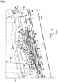
FIG. 1 is a right side view of a vehicle with a door outer panel being removed; -
FIG. 2 is a right side view of the vehicle with a side door being removed; -
FIG. 3 is an enlarged view of essential portions inFIG. 1 ; -
FIG. 4 is a sectional view of essential portions taken in the direction of arrows A-A inFIG. 3 ; -
FIG. 5 is a sectional view of essential portions taken in the direction of arrows B-B inFIG. 3 ; -
FIG. 6 is an enlarged perspective view of essential portions of a door engaging portion and a stopper seen from a rear upper side and an outer side in a vehicle width direction; -
FIG. 7 is an enlarged perspective view of essential portions of an engaging pin and a striker seen from a front upper side and the outer side in the vehicle width direction; -
FIG. 8 is a sectional view taken in the direction of arrows C-C inFIG. 6 ; and -
FIG. 9 is a perspective view ofFIG. 6 with a latchet, an engaging pin receiving portion, and a base plate being omitted, and a reinforcing panel on a rear door being shown by a phantom line. - An embodiment of the present invention will be described in detail with reference to the drawings.
- In the drawings, an arrow F indicates a front side of a vehicle, an arrow R indicates a right side of the vehicle, an arrow L indicates a left side of the vehicle, an arrow U indicates an upper side of the vehicle, an arrow OUT indicates an outer side in a vehicle width direction, and an arrow IN indicates an inner side in the vehicle width direction. In
FIGS. 2 and7 , a side door is not shown, inFIGS. 6 ,8 , and9 , a door outer panel and a center pillar are not shown. - A vehicle side structure of this embodiment is particularly symmetrical, and a configuration on the right side of the vehicle will be described unless otherwise specified.
- As shown in
FIGS. 1 and2 , the vehicle side structure of this embodiment particularly includes adoor opening 15 surrounded by aroof side rail 11, arear pillar 12, arear body 13 extending downward continuously with therear pillar 12, aside sill 7, and a hinge pillar and a front pillar (not shown) on the front side of the vehicle, and including no center pillar. - The door opening 15 is an entrance through which an occupant gets into and out of the vehicle, and particularly includes a side door 6 including a
front door 6F openably/closably mounted to a hinge pillar (not shown) on the front side of the vehicle via one or more, particularly a pair of upper and lower door hinges (not shown), and arear door 6R openably/closably mounted to therear body 13 via one or more, particularly a pair of upper and lower door hinges 16 (seeFIG. 1 ). The side door 6 (6F, 6R) includes thefront door 6F, which is a front-hinged door, and therear door 6R, which is a rear-hinged door. The side door may be or be referred to as a biparting door. - As shown in
FIG. 4 , theside sill 7 is a vehicle body rigidity member that particularly includes a side sill inner 71 having a substantially hat-shaped section protruding inward in the vehicle width direction in a section perpendicular to a front-rear direction of the vehicle (section taken in the direction of arrows A-A inFIG. 3 ), aside sill reinforcement 72 having a substantially hat-shaped section protruding outward in the vehicle width direction, and a side sill outer 73 provided on the outer side of theside sill reinforcement 72 in the vehicle width direction, forming an appearance design surface of the vehicle, and also having a substantially hat-shaped section protruding outward in the vehicle width direction, and has a side sill closedsection 7s extending in the front-rear direction of the vehicle between the side sill inner 71 and theside sill reinforcement 72. - A
floor panel 17 that forms a floor surface of a vehicle interior is particularly laid betweenside sill inners 71 of a pair of left and right side sills 7 (seeFIG. 4 ). - Describing the
side sill 7 in detail, the side sill inner 71 integrally includes aninner side wall 71a extending substantially vertically in the section perpendicular to the front-rear direction of the vehicle, an innerupper wall 71b extending substantially outward in the vehicle width direction from an upper end of theinner side wall 71a, an innerupper end flange 71c extending substantially upward from an outer end of the innerupper wall 71b in the vehicle width direction, an innerlower wall 71d extending substantially outward in the vehicle width direction from a lower end of theinner side wall 71a, and an innerlower end flange 71e extending substantially downward from an outer end of the innerlower wall 71d in the vehicle width direction. - The
side sill reinforcement 72 integrally includes aside wall 72a extending substantially vertically in the section perpendicular to the front-rear direction of the vehicle, aupper wall 72b extending substantially inward in the vehicle width direction from an upper end of theside wall 72a, aupper end flange 72c extending substantially upward from an inner end of theupper wall 72b in the vehicle width direction, alower wall 72d extending substantially inward in the vehicle width direction from a lower end of theside wall 72a, and alower end flange 72e extending substantially downward from an inner end of thelower wall 72d in the vehicle width direction. - The side sill outer 73 integrally includes an
outer side wall 73a extending substantially vertically in the section perpendicular to the front-rear direction of the vehicle, an outerupper wall 73b extending substantially inward in the vehicle width direction from an upper end of theouter side wall 73a, an outerupper end flange 73c extending substantially upward from an inner end of the outerupper wall 73b in the vehicle width direction, and an outerlower wall 73d extending substantially inward in the vehicle width direction from a lower end of theouter side wall 73a. - The inner
upper end flange 71c, theupper end flange 72c, and the outerupper end flange 73c are integrally joined by spot welding or the like so that the innerupper end flange 71c and the outerupper end flange 73c hold theupper end flange 72c therebetween, and theupper end flanges upper flange 7u of theside sill 7. - In a region of the
side sill 7 corresponding to the door opening 15 in the front-rear direction of the vehicle, a weather strip (not shown) is particularly fitted into theupper flange 7u from above. In a region corresponding to, for example, therear door 6R in the front-rear direction of the vehicle, a part of the weather strip provided between theupper flange 7u and a doorinner panel body 61 described later is pressed against theupper flange 7u and a lower part of therear door 6R (specifically, the door inner panel body 61) that faces theupper flange 7u on the outer side in the vehicle width direction when the door is closed, thereby sealing between theupper flange 7u and the door inner panel body 61 (not shown). - As shown in
FIG. 4 , the innerlower end flange 71e and thelower end flange 72e are integrally joined by spot welding or the like, and the twolower end flanges lower flange 7d of theside sill 7. The outerlower wall 73d is integrally joined to thelower wall 72d. - As shown in
FIGS. 1 and4 , therear door 6R particularly includes a doorinner panel 6i that is a panel member covering a rear part of thedoor opening 15, a door outer panel 6o (seeFIG. 4 ) located on the outer side of the doorinner panel 6i in the vehicle width direction and forming an appearance design surface of the vehicle, and acenter pillar 60 built in the door and joined to the doorinner panel 6i. - The door
inner panel 6i integrally includes the doorinner panel body 61 like a vertical wall extending vertically and in the front-rear direction of the vehicle so as to cover thedoor opening 15, a doorlower wall 62 extending substantially outward in the vehicle width direction from a lower end of the doorinner panel body 61, and a door downward extendingportion 63 extending substantially downward from an outer end of the doorlower wall 62 in the vehicle width direction (seeFIG. 4 ) . - Lower ends of the door downward extending
portion 63 and the door outer panel 6o are integrated by hemming or the like. - As shown in
FIGS. 4 and5 , a doorinternal space 6s is formed in therear door 6R, specifically, between the doorinner panel 6i and the door outer panel 6o and above the doorlower wall 62 that forms a part of a bottom surface of therear door 6R. - As shown in
FIG. 1 , ahinge reinforcement 18 extending vertically is mounted to a rear end of the doorinner panel body 61 of therear door 6R. The pair of upper and lower door hinges 16 (seeFIG. 2 ) coupling therear door 6R and therear body 13 are mounted to the rear end of the doorinner panel body 61 via a door side hinge bracket 19 (seeFIG. 1 ) provided on therear door 6R. Thehinge reinforcement 18 particularly reinforces a mounted part and therearound of the doorside hinge bracket 19 at the rear end of the doorinner panel body 61. - As shown in
FIG. 4 , when the door is closed, the lower part of the doorinner panel body 61 faces theupper flange 7u of theside sill 7 with a gap da in the vehicle width direction therebetween, and the doorlower wall 62 faces the outerupper wall 73b of theside sill 7 with a vertical gap db therebetween. - The
upper flange 7u of theside sill 7 is provided to protrude upward from the outerupper wall 73b with such a height as to substantially close the vertical gap db between the outerupper wall 73b of theside sill 7 and the doorlower wall 62 from the inner side in the vehicle width direction in a side view of the vehicle (view in the direction of arrow D inFIG. 4 ). - As shown in
FIG. 1 , thecenter pillar 60 particularly extends vertically in a front position of the doorinner panel body 61 of therear door 6R with an increasing front-to-rear width toward a lower side along a front edge of therear door 6R. Further, as shown inFIG. 5 , thecenter pillar 60 particularly has a substantially hat-shaped section protruding outward in the vehicle width direction in the section perpendicular to the vertical direction of the vehicle, and is joined to a surface of the doorinner panel body 61 on the outer side in the vehicle width direction (seeFIG. 1 ), thereby forming a center pillar closedsection 60s extending vertically between thecenter pillar 60 and the door inner panel body 61 (seeFIGS. 4 and5 ). - As shown in
FIGS. 1 ,2 , and4 , a lower end of thecenter pillar 60 is particularly joined to the door downward extendingportion 63 of the doorinner panel 6i of therear door 6R from the outer side in the vehicle width direction via a reinforcingpanel 45 described later. - As shown in
FIGS. 6 and8 , in the lower part (on the door lower wall 62) of therear door 6R and on theside sill 7 facing the lower part on the lower side, adoor engaging portion 20 and astopper 40 that engage each other between the doorlower wall 62 and theside sill 7 when the door is closed are provided adjacent to each other on the front and rear sides of the vehicle. - The
door engaging portion 20 includes, as shown inFIGS. 2 ,4 ,5 ,7 to 9 , astriker 21 provided to protrude from an upper surface of the outerupper wall 73b (hereinafter also referred to as "side sillupper surface 73b") of theside sill 7 of the vehicle body, and, as shown inFIGS. 5 and8 , adoor latch 22 that is provided on an upper surface of the door lower wall 62 (hereinafter referred to as "door inner panel lower partupper surface 62a") at the lower part of the doorinner panel 6i of therear door 6R and engages thestriker 21 when the door is closed. - Particularly as shown in
FIGS. 7 and9 , thestriker 21 on theside sill 7 integrally includes a pair ofcylindrical shafts cylindrical shaft 21a and outercylindrical shaft 21b) extending vertically from inner and outer sides in the vehicle width direction and acoupling shaft 21c that couples upper ends of thecylindrical shafts FIGS. 5 and8 , thedoor latch 22 on therear door 6R forms a part of a latch unit 23 (seeFIG. 8 ). - The
stopper 40 is an example of an engaging portion of the present invention, and includes, as shown inFIGS. 2 ,5 ,7 to 9 , an engagingpin 41 provided to protrude from a position adjacent to and on the rear side of thestriker 21 provided to protrude from the side sillupper surface 73b, and as shown inFIGS. 5 ,6 , and8 , an engagingpin receiving portion 42 that receives the engagingpin 41 brought into the doorinternal space 6s of therear door 6R when the door is closed and engages a tip (increaseddiameter portion 41a described later) of the engagingpin 41 at the time of lateral collision of the vehicle. - Specifically, the
stopper 40 is configured so that the tip of the engagingpin 41 engages the engagingpin receiving portion 42 as the lower part of therear door 6R is displaced inward in the vehicle width direction and upward at the time of lateral collision of the vehicle, thereby preventing therear door 6R from further entering inside in the vehicle width direction (vehicle interior). - As shown in
FIGS. 2 ,5 to 9 , the engagingpin 41 on theside sill 7 includes a cylindrical shaft extending vertically, and the increaseddiameter portion 41a having a larger diameter than the cylindrical shaft is integrally formed on a tip (upper end) of the cylindrical shaft. As shown inFIGS. 5 ,6 , and8 , the engagingpin receiving portion 42 on therear door 6R forms a part of apin receiving member 43. - As shown in
FIGS. 2 ,8 , and9 , thestriker 21 and the engagingpin 41 are provided on the side sillupper surface 73b via a mountingbracket 30 and adjacent to each other on the front and rear sides of the vehicle. - As shown in
FIGS. 6 and8 , thelatch unit 23 and thepin receiving member 43 are provided on the door inner panel lower partupper surface 62a via thebase plate 50 and the rear door side reinforcing panel 45 (hereinafter referred to as "reinforcingpanel 45") and adjacent to each other on the front and rear sides of the vehicle. - Specifically, the
base plate 50 to which thelatch unit 23 is mounted is expanded (extended) rearward of the vehicle up to thepin receiving member 43, and thepin receiving member 43 is also mounted to thebase plate 50. Thus, thelatch unit 23 and thepin receiving member 43 are supported on thebase plate 50 and integrated (modularized) so that they can be together assembled to an upper surface of the reinforcingpanel 45. - As shown in
FIG. 1 , anopening 61a is particularly formed in a region in a front lower part of the doorinner panel body 61 and facing thecenter pillar 60. Thelatch unit 23 and thepin receiving member 43 together mounted to thebase plate 50 are inserted through theopening 61a into the center pillar closedsection 60s from the inner side of the doorinner panel body 61 in the vehicle width direction, and assembled to the upper surface of the reinforcingpanel 45 as shown inFIGS. 3 to 5 . - As shown in
FIGS. 1 ,3 to 5 , a center pillarlower part opening 60a having such a size as to avoid interference with thebase plate 50 assembled to the upper surface of the reinforcingpanel 45 described above or thelatch unit 23 and thepin receiving member 43 integrated with thebase plate 50 is particularly formed in an outer wall lower part of thecenter pillar 60 in the vehicle width direction. - Next, the
striker 21 and the engagingpin 41 provided to protrude from the side sillupper surface 73b via the mountingbracket 30 will be described. - As shown in
FIG. 8 , the mountingbracket 30 extends in the front-rear direction of the vehicle with a length extending over at least thedoor engaging portion 20 and thestopper 40. As shown inFIGS. 7 and8 , the mountingbracket 30 includes a front mountingportion 31, amiddle mounting portion 32, and arear mounting portion 33 in front, middle, and rear parts in the front-rear direction (longitudinal direction) of the vehicle. The mountingportions upper surface 73b, and as shown inFIG. 4 , havebolt insertion holes 30h through which bolts B1 or the like can be used to mount the mountingportions upper surface 73b (only a bolt and a bolt insertion hole for mounting thefront mounting portion 31 are shown). -
FIG. 7 does not show the side sill outer 73, that is, the side sillupper surface 73b (seeFIGS. 4 and8 ) provided between the mountingbracket 30 and a side sillside reinforcing panel 25 described later. - Further, as shown in
FIGS. 7 and8 , the mountingbracket 30 particularly includes astriker seat 34 between the front mountingportion 31 and themiddle mounting portion 32 in the front-rear direction of the vehicle, and apin seat 35 between the middle mountingportion 32 and therear mounting portion 33, and is generally formed into a substantially M shape in a side view of the vehicle. - As shown in
FIG. 8 , thestriker seat 34 and thepin seat 35 are particularly formed to be raised upward from the mountingportions striker seat 34 and thepin seat 35 are slightly lower than a lower surface of the doorlower wall 62 of the doorinner panel 6i of therear door 6R when the door is closed. - As shown in
FIGS. 7 and9 , thestriker 21 is provided to protrude from thestriker seat 34 by abase 21d of thestriker 21 being mounted and supported on an upper surface (seat surface) of thestriker seat 34 using a mounting member such as a rivet. The engagingpin 41 is particularly provided to protrude from thepin seat 35 by a base 41b of the engagingpin 41 being mounted and supported on an upper surface (seat surface) of thepin seat 35 using a mounting member such as a rivet. - Thus, the
striker 21 and the engagingpin 41 are supported on the mountingbracket 30 and integrated (modularized) so that they can be together assembled to the side sillupper surface 73b. - As shown in
FIG. 8 , thestriker 21 and the engagingpin 41 both have such a height as to protrude upward of the upper surface of thebase plate 50 assembled to the door inner panel lower partupper surface 62a when the door is closed. - As shown in
FIGS. 4 ,7 , and8 , the mountingbracket 30 assembled to the side sillupper surface 73b is particularly supported by the side sill side reinforcing panel 25 (hereinafter referred to as "reinforcingpanel 25") provided under the side sillupper surface 73b via the side sillupper surface 73b. - As shown in
FIG. 8 , the reinforcingpanel 25 is mainly provided between the outerupper wall 73b of the side sill outer 73 and theupper wall 72b of theside sill reinforcement 72. As shown inFIG. 7 , a raisedportion 25a raised upward like a step from a peripheral edge in a plan view is formed at the middle, and an upper surface of the raisedportion 25a is formed to be flat so as to abut against the side sillupper surface 73b from below. - As show in
FIG. 7 , the peripheral edge of the reinforcingpanel 25 particularly includes anupper edge flange 25b extending upward from an upper edge of the raisedportion 25a, alower edge flange 25c extending downward from a lower edge, and afront edge flange 25d and arear edge flange 25e extending forward and rearward from front and rear edges. - As shown in
FIGS. 4 ,7 , and8 , theupper edge flange 25b and thelower edge flange 25c of the reinforcingpanel 25 are particularly joined to theupper end flange 72c and theside wall 72a of theside sill reinforcement 72, respectively, from the outer side in the vehicle width direction by spot welding or the like (seeFIGS. 4 and7 ), and thefront edge flange 25d and therear edge flange 25e of the reinforcingpanel 25 are joined to theupper wall 72b on the front and rear sides of the raisedportion 25a by spot welding or the like (seeFIGS. 7 and8 ) . - The raised
portion 25a of the reinforcingpanel 25 is spaced above theupper wall 72b so as to extend over theupper wall 72b in the vehicle width direction (seeFIG. 4 ), and the upper surface of the raisedportion 25a abuts against the upper surface of the outerupper wall 73b from the lower side (seeFIGS. 4 and8 ). - Further, as shown in
FIG. 4 , thefront mounting portion 31, themiddle mounting portion 32, and therear mounting portion 33 are fastened to the raisedportion 25a of the reinforcingpanel 25 so as to hold the outerupper wall 73b therebetween by the bolts B1 or the like. Thus, the raisedportion 25a of the reinforcingpanel 25 supports the mountingbracket 30 via the outerupper wall 73b (seeFIGS. 4 and8 ). - As shown in
FIGS. 5 ,6 and8 , thebase plate 50 extends in the front-rear direction of the vehicle with the length extending over at least thedoor engaging portion 20 and thestopper 40. The base plate 50A particularly includes a front mountingportion 51 and arear mounting portion 52 mounted to the door inner panel lower partupper surface 62a via the reinforcingpanel 45 on the front and rear parts, and aninclined seat 53 on which thelatch unit 23 and thepin receiving member 43 can be disposed next to each other on the front and rear sides between the front and rear mountingportions - The front mounting
portion 51 and therear mounting portion 52 havebolt insertion holes 50h (seeFIG. 5 ) through which bolts B2 or the like can be used to mount thefront mounting portion 51 and therear mounting portion 52 to the reinforcingpanel 45. - As shown in
FIGS. 6 and8 , theinclined seat 53 is particularly raised upward from the front and rear mountingportions FIGS. 5 ,6 , and8 , a latchunit mounting part 53a to which thelatch unit 23 is mounted is formed in a front position of an upper surface of theinclined seat 53. - As shown in
FIG. 5 , agroove 55 particularly extends through thebase plate 50. Thegroove 55 extends in the vehicle width direction from the latchunit mounting part 53a to the inner end in the vehicle width direction and opens inward in the vehicle width direction correspondingly to an entering trajectory along which thestriker 21 is brought into the doorinternal space 6s of therear door 6R when therear door 6R is closed. Thegroove 55 has a front-to-rear width gradually increasing inward in the vehicle width direction. - As shown in
FIGS. 5 and9 , thegroove 55 also extends through a bottom surface of ahousing 24a of thelatch body 24, the reinforcingpanel 45, and the doorinner panel 6i correspondingly to the entering trajectory along which thestriker 21 is brought into the doorinternal space 6s of therear door 6R when therear door 6R is closed. - Thus, as shown in
FIGS. 5 ,7 , and8 , thestriker 21 protruding from the mountingbracket 30 provided on theside sill 7 enters thegroove 55 from the inner side in the vehicle width direction until the outercylindrical shaft 21b of thestriker 21 reaches a deep part of the groove 55 (outer end in the vehicle width direction) when the door is closed. - The
latch unit 23 includes, as shown inFIGS. 3 to 5 and8 , thelatch body 24, and, as shown inFIGS. 3 ,4 , and6 , a vehicle width insidevertical wall 26 protruding upward, like a vertical wall, from the outer end of thelatch body 24 in the vehicle width direction so as to close the center pillarlower part opening 60a (seeFIGS. 3 to 5 ) from the inner side in the vehicle width direction. -
FIGS. 5 and8 diagrammatically show portions of an inner structure of thelatch body 24. - Particularly as shown in
FIGS. 5 and8 , thelatch body 24 includes thedoor latch 22 of a fork shape in the plan view, and thehousing 24a that houses thedoor latch 22. As shown inFIG. 5 , a base of thedoor latch 22 is journaled on ashaft 24b swingably between an engagement position P1 and a disengagement position P2 relative to thestriker 21 in the plan view. - As shown in
FIGS. 5 and8 , thedoor latch 22 is particularly located at the engagement position P1 when the door is closed, and crosses thegroove 55 so as to enter between thecylindrical shafts striker 21 to engage the outercylindrical shaft 21b of thestriker 21 at the deep part of thegroove 55 and hold a door closing state. - At this time, as shown in
FIG. 8 , thecoupling shaft 21c of thestriker 21 is particularly located above thedoor latch 22. In this example, a vertical gap (dc) is ensured between thedoor latch 22 and thecoupling shaft 21c of thestriker 21. - The
latch unit 23 is coupled to a door handle via a coupling member such as a cable (not shown). As shown inFIG. 5 , the door handle is operated so that thedoor latch 22 pivots from the engagement position P1 to the disengagement position P2 and is disengaged from thestriker 21, allowing therear door 6R to be opened. - The vehicle width inside
vertical wall 26 of thelatch unit 23 particularly has, in its inner surface in the vehicle width direction, acable holding portion 26a (seeFIG. 4 and6 ) that holds a coupling member (not shown) such as a cable extending from thelatch body 24 to the door handle (not shown). - As shown in
FIGS. 5 ,6 , and8 , a pin receivingmember mounting part 53b to which thepin receiving member 43 is mounted is formed on a rear position of the upper surface of theinclined seat 53. - The
pin receiving member 43 particularly includes the flat engagingpin receiving portion 42 at its bottom, and a lower surface of the engagingpin receiving portion 42 is integrally joined to the pin receivingmember mounting part 53b of theinclined seat 53. - As shown in
FIG. 5 , agroove 56 particularly extends through thebase plate 50. Thegroove 56 extends in the vehicle width direction from the pin receivingmember mounting part 53b to the inner end in the vehicle width direction and opens inward in the vehicle width direction correspondingly to an entering trajectory along which the engagingpin 41 is brought into (enters) the doorinternal space 6s of therear door 6R when therear door 6R is closed. Thegroove 56 has a front-to-rear width gradually increasing inward in the vehicle width direction. - As shown in
FIGS. 5 and9 , thegroove 56 also extends through the engagingpin receiving portion 42 of thepin receiving member 43, the reinforcingpanel 45, and the doorinner panel 6i correspondingly to the entering trajectory along which the engagingpin 41 is brought into the doorinternal space 6s of therear door 6R when therear door 6R is closed. - Thus, as shown in
FIGS. 5 ,7 , and8 , the engagingpin 41 protruding from the mountingbracket 30 provided on theside sill 7 enters thegroove 56 from the inner side in the vehicle width direction until the engagingpin 41 reaches a deep part of the groove 56 (outer end in the vehicle width direction) when the door is closed. - As shown in
FIGS. 6 to 8 , with the engagingpin 41 having entered the deep part of thegroove 56 when the door is closed being inserted into thegroove 56 from below, the increaseddiameter portion 41a is located above the upper surface of the engagingpin receiving portion 42. Thus, at the time of lateral collision of the vehicle, the increaseddiameter portion 41a of the engagingpin 41 engages a peripheral edge at the deep part of thegroove 56, that is, the engagingpin receiving portion 42 to prevent the lower part of therear door 6R from being deformed upward. - Specifically, as shown in
FIGS. 5 ,6 , and8 , the pin receivingmember mounting part 53b of thebase plate 50 corresponds to the peripheral edge at the deep part of thegroove 56, and as described above, thepin receiving member 43 is integrally joined to the pin receivingmember mounting part 53b, and thus the flat engagingpin receiving portion 42 surrounds, particularly, the deep part of thegroove 56 in the plan view to reinforce the peripheral edge at the deep part of thegroove 56 against a lateral collision load. - As shown in
FIG. 8 , the vertical space (dc) between thedoor latch 22 and thestriker 21 is particularly set to be equal to the vertical space (dd) between the increaseddiameter portion 41a of the engagingpin 41 and the engagingpin receiving portion 42 when the door is closed. - Specifically, as described above, the
coupling shaft 21c of thestriker 21 and thedoor latch 22 ensures the vertical gap therebetween and the increaseddiameter portion 41a of the engagingpin 41 and the engagingpin receiving portion 42 ensures the vertical gap therebetween when the door is closed, and particularly in this example, the vertical spaces dc, dd are set to be equal (dc = dd (seeFIG. 8 )). - The
door engaging portion 20 and thestopper 40 described above are disposed in an orientation corresponding to an opening/closing trajectory of therear door 6R. - Specifically, as shown in
FIG. 8 , the upper surface of theinclined seat 53 is particularly inclined so that the front side of the vehicle is higher than the rear side of the vehicle in the plan view of the vehicle and the outer side in the vehicle width direction is higher than the inner side in the vehicle width direction in a front view of the vehicle. - Further, as shown in
FIGS. 5 and9 , correspondingly to the door opening/closing trajectory, thegroove 55 that thestriker 21 can enter and thegroove 56 that is provided in the lower part of therear door 6R and that the engagingpin 41 can enter open slightly inclined rearward toward the inner side in the vehicle width direction relative to the vehicle width direction. - Similarly, correspondingly to the door opening/closing trajectory, the
striker 21 is particularly supported on the seat surface of thestriker seat 34 slightly inclined rearward toward the inner side in the vehicle width direction relative to the vehicle width direction (seeFIG. 5 ). - From the above, the
striker 21 and the engagingpin 41 can be smoothly guided without interfering with or scraping thelatch body 24 and thepin receiving member 43, respectively, when therear door 6R is opened/closed. - As described above, the upper surface of the
inclined seat 53 is particularly inclined so that the front side of the vehicle is higher than the rear side of the vehicle in the plan view of the vehicle. Besides, as shown inFIGS. 6 ,8 , and9 , the doorlower wall 62 of the doorinner panel 6i of therear door 6R and the reinforcingpanel 45 are formed so that anupper surface 45f (hereinafter referred to as "step-upportion 45f") on the front side of the latchunit mounting part 53a in the front-rear direction of the vehicle is higher, via astep 45a, than anupper surface 45r (hereinafter referred to as "step-downportion 45r") on the rear side of the latchunit mounting part 53a. - The
base plate 50 is assembled to the upper surface of the reinforcingpanel 45 so that theinclined seat 53 extends over thestep 45a. - Further, even with the
base plate 50 being assembled to the upper surface of the reinforcingpanel 45 so as to extend over thestep 45a of the reinforcingpanel 45, thefront mounting portion 51 and therear mounting portion 52 are formed to be flat and substantially horizontal so as to be placed in surface contact with the horizontal and flat step-upportion 45f and step-downportion 45r on the upper surface of the reinforcing panel 45 (seeFIG. 8 ) . - Thus, the
base plate 50 that supports thelatch unit 23 and thepin receiving member 43 is assembled to the upper surface of the reinforcingpanel 45, thereby allowing thelatch unit 23 and thepin receiving member 43 to be easily assembled in the orientation corresponding to the opening/closing trajectory of therear door 6R without requiring precise adjustment of assembling angles or the like. - As described above, the
door engaging portion 20 and thestopper 40 are particularly disposed in the front lower part of the doorinner panel 6i of therear door 6R (seeFIGS. 1 to 9 , particularlyFIG. 2 ). - In other words, as shown in
FIG. 2 , thedoor engaging portion 20 and thestopper 40 are disposed in positions spaced apart from thedoor hinge 16 at the rear end of the doorinner panel 6i of therear door 6R as much as possible in the front-rear direction of the vehicle, that is, in the front position of the doorinner panel 6i. - Further, in this embodiment, as shown in
FIG. 2 , for thedoor engaging portion 20 and thestopper 40 disposed adjacent to each other in the front-rear direction of the vehicle, thedoor engaging portion 20 is disposed on the front side of thestopper 40, and thus disposed in a position (La>Lb) spaced further forward from thedoor hinge 16 at the rear end of therear door 6R. - As such, for the
door engaging portion 20 and thestopper 40, particularly thedoor engaging portion 20 is provided on the front side of therear door 6R as close as possible to a boundary with thefront door 6F in the front-rear direction of the vehicle, thereby allowing stable engagement of thedoor engaging portion 20 and minimizing displacement of therear door 6R relative to thefront door 6F when the door is closed. - As shown in
FIGS. 1 to 9 , the vehicle side structure of this embodiment described above includes thestopper 40 as an engaging portion that is at least partially provided between the door lower wall 62 (lower part of therear door 6R) of the doorinner panel 6i of therear door 6R of the side door 6 and theside sill 7 and provides engagement between the doorlower wall 62 and theside sill 7. Thestopper 40 includes the engaging pin 41 (seeFIGS. 2 ,7 to 9 ) provided to protrude from the side sillupper surface 73b, and the engagingpin receiving portion 42 that is provided on the doorlower wall 62, receives the engagingpin 41 brought into the doorinternal space 6s above the doorlower wall 62, and engages the increaseddiameter portion 41a (tip) of the engaging pin 41 (seeFIGS. 5 ,6 , and8 ). - According to the above described configuration, the increased
diameter portion 41a of the engagingpin 41 provided on the side sillupper surface 73b engages the engagingpin receiving portion 42 provided in the lower part of therear door 6R at the time of lateral collision of the vehicle, thereby preventing therear door 6R from entering the vehicle interior. - According to the above described configuration, the engaging
pin 41 or the engagingpin receiving portion 42 can be prevented from damaging the side sillupper surface 73b or the lower surface of the doorlower wall 62, and the lower surface of the doorlower wall 62 of therear door 6R can be lowered to reduce the height of the side sill 7 (particularly, theupper flange 7u) over which the occupant steps when getting into the vehicle. - Specifically, for example, a conventional engaging portion (stopper) (not shown) including an engaging pin provided to protrude downward from a door lower surface, and an engaging pin receiving portion provided on a side sill upper surface so as to be engageable with the engaging pin may be configured so that the engaging pin receiving portion provided on the side sill upper surface is introduced (brought) into a door lower part when a door is closed and that the engaging pin is received in the engaging pin receiving portion for engagement in the door lower part.
- However, such a conventional configuration requires providing, in the door lower part, a space into which the engaging pin receiving portion larger than the engaging pin can be introduced when the door is closed, and also providing the engaging pin protruding downward in the same position as the space, which may provide a complex configuration of the door lower part and hinder formability of a door inner panel.
- Specifically, with the conventional configuration including the engaging pin provided to protrude downward from the door lower surface, and the engaging pin receiving portion that is provided in the side sill upper surface and receives the engaging pin, it is difficult to accommodate a height of the engaging pin receiving portion by introducing the engaging pin receiving portion into the door for engagement between a tip of the engaging pin and the engaging pin receiving portion
- Thus, a conventional configuration is found in which an engaging pin receiving portion is not introduced into a door when the door is closed, but a gap in which the engaging pin receiving portion is placed is provided between a door lower surface and a side sill upper surface, and the engaging pin receiving portion placed in the gap receives an engaging pin provided to protrude from the door lower surface (see, for example, Japanese Patent Laid-Open No.
2003-11778 - However, in an attempt to engage a tip of the engaging pin with the engaging pin receiving portion in the slight vertical gap between the door lower surface and the side sill upper surface, the engaging pin protruding downward may damage the side sill upper surface or the engaging pin receiving portion provided on the side sill upper surface may damage a side door lower surface when the door is closed.
- If a gap between the door lower surface and the side sill upper surface is ensured by increasing a height of the door lower surface, an upper flange (rising portion) of the side sill rising that rises from the side sill upper surface on which the engaging pin receiving portion is provided on an inner side in a vehicle width direction (vehicle interior side) needs to have a large height so as to close the gap from the inner side in the vehicle width direction. This may prevent the occupant from smoothly stepping over the side sill and getting into the vehicle.
- On the other hand, as described above, in this embodiment, the engaging
pin 41 is provided to protrude from the side sillupper surface 73b, and the engagingpin receiving portion 42 is provided in the lower part of therear door 6R. Thus, the doorinternal space 6s accommodates the height of the engagingpin receiving portion 42, and the engagingpin 41 brought into the doorinternal space 6s of therear door 6R can be received by the engagingpin receiving portion 42 provided on the door inner panel lower partupper surface 62a, that is, on the side of the doorinternal space 6s of therear door 6R to provide engagement between the increaseddiameter portion 41a at the tip of the engagingpin 41 and the engagingpin receiving portion 42. - Thus, according to the above described configuration, the engaging
pin receiving portion 42 can be prevented from damaging the side sillupper surface 73b, or the engagingpin 41 can be prevented from damaging the lower surface of therear door 6R. Also, there is no need to ensure a gap in which the engagingpin receiving portion 42 is disposed between the side sillupper surface 73b and the lower surface of therear door 6R, and thus the lower surface of therear door 6R (the lower surface of the door lower wall 62) can be lowered, thereby reducing the height of the side sill 7 (particularly theupper flange 7u) over which the occupant steps when getting into the vehicle. - As an aspect of the present invention, the
striker 21 is provided adjacent to thestopper 40 to protrude from the side sillupper surface 73b (seeFIGS. 2 ,5 ,7 , and9 ), and thelatch unit 23 including thedoor latch 22 that engages thestriker 21 when the door is closed is provided in the lower part of therear door 6R, that is, on the door inner panel lower partupper surface 62a (seeFIGS. 4 to 6 , and8 ). - According to the above described configuration, the
stopper 40 including the engagingpin 41 and the engagingpin receiving portion 42 and thedoor engaging portion 20 including thestriker 21 and thedoor latch 22 can be provided adjacent to each other and cooperate to receive a lateral collision load at the time of lateral collision of the vehicle. - As an aspect of the present invention, the
door engaging portion 2 including thedoor latch 22 and thestriker 21 is provided farther from thedoor hinge 16 of therear door 6R than the stopper 40 (La>Lb) (seeFIGS. 1 to 3 , particularlyFIG. 2 ). - According to the above described configuration, positioning performance of the
rear door 6R can be improved by latch engagement of thedoor engaging portion 20 when the door is closed. - As an aspect of the present invention, the
base plate 50 for mounting thelatch body 24 partially including thedoor latch 22 to the door inner panel lower partupper surface 62a is provided (seeFIGS. 3 to 6 , and 8), thebase plate 50 is expanded to the engagingpin receiving portion 42, and the engagingpin receiving portion 42 is mounted to the base plate 50 (seeFIGS. 5 ,6 , and8 ). - According to the above described configuration, the
latch body 24 and the engagingpin receiving portion 42 can be mounted to the door inner panel lower partupper surface 62a via thebase plate 50 as a common member. This facilitates control of relative heights of thelatch body 24 and the engagingpin receiving portion 42, and allows thedoor latch 22 and the engagingpin receiving portion 42 to behave in the same manner at the time of lateral collision of the vehicle. - As an aspect of the present invention, the vertical space (dc) between the
door latch 22 and thestriker 21 is set to be equal to the vertical space (dd) between the engagingpin 41 and the engaging pin receiving portion 42 (seeFIG. 8 ). - According to the above described configuration, when the lower part of the
rear door 6R moves upward at the time of lateral collision of the vehicle, thedoor latch 22 can engage thestriker 21 and the engagingpin 41 can engage the engagingpin receiving portion 42 at the same timing. Thus, a load can be simultaneously applied to thestriker 21 and the engagingpin 41 at the time of lateral collision of the vehicle, and thestriker 21 and the engagingpin 41 can cooperate to efficiently receive the lateral collision load. - As described above, for setting the vertical space (dc) between the
door latch 22 and thestriker 21 to be equal to the vertical space (dd) between the engagingpin 41 and the engagingpin receiving portion 42, the engagingpin 41 is provided to protrude from the side sillupper surface 73b, and the engagingpin receiving portion 42 is provided on the door inner panel lower partupper surface 62a so as to receive the engagingpin 41 brought into the doorinternal space 6s of therear door 6R to be engageable with the increaseddiameter portion 41a of the engagingpin 41 when the door is closed. Thus, particularly more remarkably, the engagingpin 41 or the engagingpin receiving portion 42 can be prevented from damaging the side sillupper surface 73b or the lower surface of the doorlower wall 62 when the door is closed, and the lower surface of the doorlower wall 62 of therear door 6R can be lowered. - Specifically, in the conventional configuration in which, for example, the engaging pin is provided to protrude downward from the rear door lower surface, and the engaging pin receiving portion is provided on the side sill upper surface, if, for example, the engaging pin is formed to protrude downward (toward the side sill) so that the gap between the door latch and the striker is set to be equal to the gap between the tip of the engaging pin and the engaging pin receiving portion, the pin may damage the side sill upper surface.
- Thus, for example, a position of the engaging pin receiving portion may be raised on the side of the side door.
- However, in the conventional configuration in which the engaging pin is provided to protrude downward from the rear door lower surface, and the engaging pin receiving portion is provided on the side sill upper surface, as described above, there is a need to introduce the engaging pin receiving portion into the side door and also to support the pin protruding downward in the same region in the lower part of the side door when the door is closed, which is disadvantageous in terms of formability of the door inner panel or the like. Specifically, simply raising the position of the engaging pin receiving portion on the side of the side door as described above makes it difficult for the inside of the lower part of the side door to accommodate the height of the engaging pin receiving portion when the door is closed.
- For raising the position of the engaging pin receiving portion on the side of the side door, the side door lower surface may be raised so as to prevent interference with the side door lower surface. However, in that case, with increasing height of the side door lower surface, the position of the door latch provided in the lower part of the side door becomes higher, and thus the striker provided to protrude from the side sill upper surface needs to be formed to further protrude upward.
- The gap between the side door lower surface and the side sill upper surface increases as the height of the striker or the engaging pin receiving portion increases. Thus, as described above, the rising portion (upper flange), which is provided to protrude from the surface of the side sill on which the engaging pin receiving portion is provided, needs to have a larger height so as to close the gap from the inner side in the vehicle width direction (vehicle interior side). This may prevent the occupant from stepping over the side sill and smoothly getting into the vehicle.
- On the other hand, in this embodiment, as described above, for setting the vertical space (dc) between the
door latch 22 and thestriker 21 to be equal to the vertical space (dd) between the engagingpin 41 and the engaging pin receiving portion 42 (seeFIG. 8 ), the engagingpin 41 is provided to protrude from the side sillupper surface 73b, and the engagingpin receiving portion 42 is provided on the door inner panel lower partupper surface 62a so as to receive the engagingpin 41 brought into the doorinternal space 6s of therear door 6R to be engageable with the increaseddiameter portion 41a of the engagingpin 41 when the door is closed. Thus, particularly more remarkably, the engagingpin 41 or the engagingpin receiving portion 42 can be prevented from damaging the side sillupper surface 73b or the lower surface of the doorlower wall 62 when the door is closed, and the lower surface of the doorlower wall 62 of therear door 6R can be lowered. - The present invention is not limited to the configuration of the above described embodiment, but is susceptible of various embodiments.
- In the present invention, as in the above described embodiment, the
stopper 40 and thedoor engaging portion 20 can be applied between the lower part of therear door 6R and theside sill 7, but not limited to this, may be applied to thefront door 6F or both thedoors - The engaging portion of the present invention is not limited to the
stopper 40 that prevents therear door 6R from entering the vehicle interior at the time of lateral collision of the vehicle as described above, but may include, for example, a configuration in which an engaging pin engages an engaging pin receiving portion to guide and position therear door 6R to and in a predetermined position relative to theside sill 7 when door is closed, or to ensure support rigidity of the seat belt provided on the side door. -
- 6R rear door (side door)
- 6s door internal space (space above lower part of side door)
- 7 side sill
- 16 door hinge
- 20 door latch engaging portion
- 21 striker
- 22 door latch
- 24 latch body
- 40 stopper (engaging portion)
- 41 engaging pin
- 41a increased diameter portion (tip of engaging pin)
- 42 engaging pin receiving portion
- 50 base plate
- 62 door lower wall (lower part of side door)
- 73b outer upper wall, side sill upper surface
- db vertical gap between door lower wall and outer upper wall (between lower part of side door and side sill)
- dc vertical space between door latch and striker
- dd vertical space between engaging pin and engaging pin receiving portion
Claims (15)
- A vehicle side structure comprising:a side door (6R);a side sill (7) located below the side door (6R); andan engaging portion (40) configured to provide engagement between a lower part (62) of the side door (6R) and the side sill (7), the engaging portion (40) including:an engaging pin (41) provided to protrude upward from an upper surface (73b) of the side sill (7) and having a tip (41a); andan engaging pin receiving portion (42) that is provided in the lower part (62) of the side door (6R) and configured to receive the engaging pin (41) brought into a space (6s) above the lower part (62) of the side door (6R), the engaging pin receiving portion (42) being adapted to receive the engaging pin (41) brought into the space (6s) above the lower part (62) of the side door (6R) without interference when the side door (6R) is closed, and to release the engaging pin (41) without interference when the side door (6R) is opened,wherein the tip (41a) of the engaging pin (41) is configured to engage the engaging pin receiving portion (42) at least at the time of lateral collision.
- The vehicle side structure according to claim 1, wherein a striker (21) is provided adjacent to the engaging portion (40) to protrude upward from the upper surface (73b) of the side sill (7), and a door latch (22) is provided in the lower part (62) of the side door (6R), the door latch (22) being adapted to engage the striker (21) when the side door (6R) is closed.
- The vehicle side structure according to claim 2, wherein a door latch engaging portion (20) including the door latch (22) and the striker (21) is provided farther from a door hinge (16) of the side door (6R) than the engaging portion (40).
- The vehicle side structure according to claim 2 or 3, further comprising a base plate (50) configured to mount a latch body (24) partially including the door latch (22) to the lower part (62) of the side door (6R), wherein
the base plate (50) is expanded to the engaging pin receiving portion (42), and the engaging pin receiving portion (42) is mounted to the base plate (50). - The vehicle side structure according to any one of claims 2 to 4, wherein a vertical space (dc) between the door latch (22) and the striker (21) is set to be equal to a vertical space (dd) between the engaging pin (41) and the engaging pin receiving portion (42).
- The vehicle side structure according to any one of claims 2 to 5, wherein
the striker (21) and the engaging pin (41) are provided on the upper surface (73b) via a mounting bracket (30). - The vehicle side structure according to claim 6, wherein
the mounting bracket (30) is assembled to the upper surface (73b) by a reinforcing panel (25) provided under the upper surface (73b). - The vehicle side structure according to claim 7, wherein
the reinforcing panel (25) has a raised portion (25a) raised upward from a peripheral edge in a plan view. - The vehicle side structure according to claim 8, wherein
the raised portion (25a) is formed to be flat so as to abut against the upper surface (73b) from below. - The vehicle side structure according to any one of the preceding claims, wherein
the engaging pin receiving portion (42) includes a groove (56), and
the engaging pin (41) is configured to enter into the groove (56). - The vehicle side structure according to any one of the preceding claims, wherein
the tip (41a) of the engaging pin (41) is configured to engage with the engaging pin receiving portion (42) as the lower part of the side door (6R) is displaced inward in the vehicle width direction and/or upward. - The vehicle side structure according to any one of the preceding claims, wherein
a hinge reinforcement (18) is mounted to a rear end of the side door (6R). - The vehicle side structure according to any one of the preceding claims, wherein
the tip (41a) has an increased diameter. - The vehicle side structure according to any one of the preceding claims, wherein
the engaging pin (41) includes a cylindrical shaft extending vertically, and the tip (41a), and
the tip (41a) has a larger diameter than a diameter of the cylindrical shaft. - A vehicle comprising a vehicle side structure according to any one of the preceding claims.
Applications Claiming Priority (1)
| Application Number | Priority Date | Filing Date | Title |
|---|---|---|---|
| JP2018119697A JP7234516B2 (en) | 2018-06-25 | 2018-06-25 | vehicle side structure |
Publications (1)
| Publication Number | Publication Date |
|---|---|
| EP3587155A1 true EP3587155A1 (en) | 2020-01-01 |
Family
ID=66912681
Family Applications (1)
| Application Number | Title | Priority Date | Filing Date |
|---|---|---|---|
| EP19180517.5A Withdrawn EP3587155A1 (en) | 2018-06-25 | 2019-06-17 | Vehicle side structure and vehicle |
Country Status (3)
| Country | Link |
|---|---|
| US (1) | US11383588B2 (en) |
| EP (1) | EP3587155A1 (en) |
| JP (1) | JP7234516B2 (en) |
Cited By (5)
| Publication number | Priority date | Publication date | Assignee | Title |
|---|---|---|---|---|
| DE102020210819A1 (en) | 2020-08-27 | 2022-03-03 | Volkswagen Aktiengesellschaft | Arrangement for a vehicle, vehicle |
| EP4137341A1 (en) * | 2021-08-19 | 2023-02-22 | Audi AG | Wheeled vehicle |
| EP4273357A1 (en) * | 2022-05-04 | 2023-11-08 | Ningbo Geely Automobile Research & Development Co. Ltd. | Striker system, vehicle comprising a striker system and method for assembling a striker system |
| US11839754B2 (en) | 2016-10-25 | 2023-12-12 | Magenta Medical Ltd | Ventricular assist device |
| EP4259897A4 (en) * | 2020-12-09 | 2024-10-30 | Magna International Inc. | MODULAR, INDIVIDUALLY OPERATED VEHICLE DOOR |
Families Citing this family (5)
| Publication number | Priority date | Publication date | Assignee | Title |
|---|---|---|---|---|
| FR3069004B1 (en) * | 2017-07-13 | 2021-04-09 | Lisi Aerospace | LOCK AND AIRCRAFT STRIKE WITH SUCH STRIKE |
| SE541218C2 (en) * | 2017-09-20 | 2019-05-07 | Gestamp Hardtech Ab | A vehicle side structure |
| JP7070068B2 (en) * | 2018-05-14 | 2022-05-18 | マツダ株式会社 | Vehicle side body structure |
| JP7159638B2 (en) * | 2018-06-25 | 2022-10-25 | マツダ株式会社 | vehicle door structure |
| DE102021111208A1 (en) * | 2020-05-28 | 2021-12-02 | Magna Closures Inc. | Main and secondary locks for locks on motor vehicles |
Citations (6)
| Publication number | Priority date | Publication date | Assignee | Title |
|---|---|---|---|---|
| FR1511947A (en) * | 1966-02-23 | 1968-02-02 | Mecanismes Comp Ind De | Improvements to door maintenance means |
| DE2028249B1 (en) * | 1970-06-09 | 1972-03-09 | Audi Nsu Auto Union Ag, 7107 Neckarsulm | Protection device against side impact in accidents on motor vehicles |
| DE3103580A1 (en) * | 1980-02-04 | 1982-01-07 | The Budd Co., 48084 Troy, Mich. | REINFORCEMENT DEVICE FOR A DOOR IN A MOTOR VEHICLE |
| US5306067A (en) * | 1993-01-25 | 1994-04-26 | Ford Motor Company | Rear door assembly for automobiles |
| JP2003011778A (en) | 2001-07-04 | 2003-01-15 | Mazda Motor Corp | Seat belt structure for vehicle |
| FR2996171A1 (en) * | 2012-10-02 | 2014-04-04 | Peugeot Citroen Automobiles Sa | Device for centering and retaining sliding side door of car during impact, has retaining hook deformed during impact of car to prevent opening of side door, where centering finger and retaining hook are integrated as single part |
Family Cites Families (5)
| Publication number | Priority date | Publication date | Assignee | Title |
|---|---|---|---|---|
| JPS57192817U (en) * | 1981-06-03 | 1982-12-07 | ||
| JPS59151819U (en) * | 1983-03-31 | 1984-10-11 | 三菱自動車工業株式会社 | door device |
| DE3942522C2 (en) * | 1989-12-22 | 1994-12-08 | Wagener Gmbh Fritz | Model vehicle with side door |
| JP4055186B2 (en) | 2002-10-28 | 2008-03-05 | 関東自動車工業株式会社 | Side-pillar load adjustment structure for center pillarless vehicles |
| US7819465B2 (en) * | 2008-12-22 | 2010-10-26 | Ford Global Technologies, Llc | Transferable B-pillar for facilitating ingress/egress |
-
2018
- 2018-06-25 JP JP2018119697A patent/JP7234516B2/en active Active
-
2019
- 2019-06-17 EP EP19180517.5A patent/EP3587155A1/en not_active Withdrawn
- 2019-06-19 US US16/446,182 patent/US11383588B2/en active Active
Patent Citations (6)
| Publication number | Priority date | Publication date | Assignee | Title |
|---|---|---|---|---|
| FR1511947A (en) * | 1966-02-23 | 1968-02-02 | Mecanismes Comp Ind De | Improvements to door maintenance means |
| DE2028249B1 (en) * | 1970-06-09 | 1972-03-09 | Audi Nsu Auto Union Ag, 7107 Neckarsulm | Protection device against side impact in accidents on motor vehicles |
| DE3103580A1 (en) * | 1980-02-04 | 1982-01-07 | The Budd Co., 48084 Troy, Mich. | REINFORCEMENT DEVICE FOR A DOOR IN A MOTOR VEHICLE |
| US5306067A (en) * | 1993-01-25 | 1994-04-26 | Ford Motor Company | Rear door assembly for automobiles |
| JP2003011778A (en) | 2001-07-04 | 2003-01-15 | Mazda Motor Corp | Seat belt structure for vehicle |
| FR2996171A1 (en) * | 2012-10-02 | 2014-04-04 | Peugeot Citroen Automobiles Sa | Device for centering and retaining sliding side door of car during impact, has retaining hook deformed during impact of car to prevent opening of side door, where centering finger and retaining hook are integrated as single part |
Cited By (8)
| Publication number | Priority date | Publication date | Assignee | Title |
|---|---|---|---|---|
| US11839754B2 (en) | 2016-10-25 | 2023-12-12 | Magenta Medical Ltd | Ventricular assist device |
| DE102020210819A1 (en) | 2020-08-27 | 2022-03-03 | Volkswagen Aktiengesellschaft | Arrangement for a vehicle, vehicle |
| EP4259897A4 (en) * | 2020-12-09 | 2024-10-30 | Magna International Inc. | MODULAR, INDIVIDUALLY OPERATED VEHICLE DOOR |
| US12331565B2 (en) | 2020-12-09 | 2025-06-17 | Magna International Inc. | Modular individually operable vehicle door |
| EP4137341A1 (en) * | 2021-08-19 | 2023-02-22 | Audi AG | Wheeled vehicle |
| US12122223B2 (en) | 2021-08-19 | 2024-10-22 | Audi Ag | Vehicle |
| EP4273357A1 (en) * | 2022-05-04 | 2023-11-08 | Ningbo Geely Automobile Research & Development Co. Ltd. | Striker system, vehicle comprising a striker system and method for assembling a striker system |
| WO2023213212A1 (en) * | 2022-05-04 | 2023-11-09 | Ningbo Geely Automobile Research & Development Co., Ltd. | Striker system, vehicle comprising a striker system and method for assembling a striker system |
Also Published As
| Publication number | Publication date |
|---|---|
| JP2020001429A (en) | 2020-01-09 |
| US20190390491A1 (en) | 2019-12-26 |
| JP7234516B2 (en) | 2023-03-08 |
| US11383588B2 (en) | 2022-07-12 |
Similar Documents
| Publication | Publication Date | Title |
|---|---|---|
| US11383588B2 (en) | Vehicle side structure | |
| US8414038B2 (en) | Vehicle door latch structure | |
| US7520557B2 (en) | Side structure of vehicle | |
| EP2397352B1 (en) | Vehicle door structure | |
| CN113276640B (en) | door structure | |
| US20060181107A1 (en) | Vehicle door | |
| JP4800030B2 (en) | Window glass lifting device | |
| JP2010083167A (en) | Slide door structure of vehicle | |
| JP2004291958A (en) | C pillar and rear door hinge structure of vehicle without B pillar | |
| JPH02225130A (en) | Sunshine roof construction of automobile | |
| JP4526359B2 (en) | Vehicle door | |
| JP3907117B2 (en) | Vehicle tailgate structure | |
| US5890755A (en) | Glove box door latch assembly | |
| JP2006226042A (en) | Stopper structure of slide door | |
| JP3818890B2 (en) | Automobile beltline structure | |
| JP7415375B2 (en) | Vehicle side structure | |
| JPH0737957Y2 (en) | Rail mounting structure for automobile sliding doors | |
| JP3991965B2 (en) | Car sliding door structure | |
| CN108146195B (en) | Vehicle door structure | |
| JP4602245B2 (en) | Door handle structure | |
| JP7716654B2 (en) | Vehicle door structure | |
| JP3818868B2 (en) | Belt line structure for automobile doors | |
| JP7803255B2 (en) | Vehicle undercarriage | |
| JP5621731B2 (en) | Sash assembly structure for vehicle doors | |
| JPH0687014U (en) | Door glass guide structure |
Legal Events
| Date | Code | Title | Description |
|---|---|---|---|
| PUAI | Public reference made under article 153(3) epc to a published international application that has entered the european phase |
Free format text: ORIGINAL CODE: 0009012 |
|
| STAA | Information on the status of an ep patent application or granted ep patent |
Free format text: STATUS: THE APPLICATION HAS BEEN PUBLISHED |
|
| AK | Designated contracting states |
Kind code of ref document: A1 Designated state(s): AL AT BE BG CH CY CZ DE DK EE ES FI FR GB GR HR HU IE IS IT LI LT LU LV MC MK MT NL NO PL PT RO RS SE SI SK SM TR |
|
| AX | Request for extension of the european patent |
Extension state: BA ME |
|
| STAA | Information on the status of an ep patent application or granted ep patent |
Free format text: STATUS: REQUEST FOR EXAMINATION WAS MADE |
|
| 17P | Request for examination filed |
Effective date: 20200625 |
|
| RBV | Designated contracting states (corrected) |
Designated state(s): AL AT BE BG CH CY CZ DE DK EE ES FI FR GB GR HR HU IE IS IT LI LT LU LV MC MK MT NL NO PL PT RO RS SE SI SK SM TR |
|
| GRAP | Despatch of communication of intention to grant a patent |
Free format text: ORIGINAL CODE: EPIDOSNIGR1 |
|
| STAA | Information on the status of an ep patent application or granted ep patent |
Free format text: STATUS: GRANT OF PATENT IS INTENDED |
|
| INTG | Intention to grant announced |
Effective date: 20210330 |
|
| RIN1 | Information on inventor provided before grant (corrected) |
Inventor name: YOKOGAWA, JUNYA Inventor name: HORITA, YOSHIHIKO Inventor name: NAKAZATO, DAISUKE Inventor name: TAKAHASHI, TOMOKI Inventor name: SHOKI, ISHII |
|
| STAA | Information on the status of an ep patent application or granted ep patent |
Free format text: STATUS: THE APPLICATION IS DEEMED TO BE WITHDRAWN |
|
| 18D | Application deemed to be withdrawn |
Effective date: 20210810 |