EP3587148A1 - Method and system for preventing instability in a vehicle-trailer combination - Google Patents
Method and system for preventing instability in a vehicle-trailer combination Download PDFInfo
- Publication number
- EP3587148A1 EP3587148A1 EP19188625.8A EP19188625A EP3587148A1 EP 3587148 A1 EP3587148 A1 EP 3587148A1 EP 19188625 A EP19188625 A EP 19188625A EP 3587148 A1 EP3587148 A1 EP 3587148A1
- Authority
- EP
- European Patent Office
- Prior art keywords
- trailer
- vehicle
- sensing means
- yaw
- determining
- Prior art date
- Legal status (The legal status is an assumption and is not a legal conclusion. Google has not performed a legal analysis and makes no representation as to the accuracy of the status listed.)
- Granted
Links
- 238000000034 method Methods 0.000 title claims abstract description 75
- 230000003287 optical effect Effects 0.000 claims abstract description 29
- 230000033001 locomotion Effects 0.000 claims abstract description 22
- 238000012544 monitoring process Methods 0.000 claims abstract description 11
- 230000007935 neutral effect Effects 0.000 claims description 20
- 238000004590 computer program Methods 0.000 claims description 15
- 238000004458 analytical method Methods 0.000 claims description 8
- 230000010355 oscillation Effects 0.000 description 9
- 239000002131 composite material Substances 0.000 description 6
- 238000005259 measurement Methods 0.000 description 6
- 238000013459 approach Methods 0.000 description 3
- 238000001514 detection method Methods 0.000 description 3
- 238000010586 diagram Methods 0.000 description 3
- 230000000694 effects Effects 0.000 description 3
- 230000002411 adverse Effects 0.000 description 2
- 238000013016 damping Methods 0.000 description 2
- 239000000428 dust Substances 0.000 description 2
- 238000001914 filtration Methods 0.000 description 2
- 238000012545 processing Methods 0.000 description 2
- 230000000007 visual effect Effects 0.000 description 2
- 201000009482 yaws Diseases 0.000 description 2
- 230000033228 biological regulation Effects 0.000 description 1
- 230000002596 correlated effect Effects 0.000 description 1
- 230000000875 corresponding effect Effects 0.000 description 1
- 238000006073 displacement reaction Methods 0.000 description 1
Images


Classifications
-
- B—PERFORMING OPERATIONS; TRANSPORTING
- B60—VEHICLES IN GENERAL
- B60D—VEHICLE CONNECTIONS
- B60D1/00—Traction couplings; Hitches; Draw-gear; Towing devices
- B60D1/24—Traction couplings; Hitches; Draw-gear; Towing devices characterised by arrangements for particular functions
- B60D1/30—Traction couplings; Hitches; Draw-gear; Towing devices characterised by arrangements for particular functions for sway control, e.g. stabilising or anti-fishtail devices; Sway alarm means
- B60D1/305—Sway alarm means
-
- B—PERFORMING OPERATIONS; TRANSPORTING
- B60—VEHICLES IN GENERAL
- B60W—CONJOINT CONTROL OF VEHICLE SUB-UNITS OF DIFFERENT TYPE OR DIFFERENT FUNCTION; CONTROL SYSTEMS SPECIALLY ADAPTED FOR HYBRID VEHICLES; ROAD VEHICLE DRIVE CONTROL SYSTEMS FOR PURPOSES NOT RELATED TO THE CONTROL OF A PARTICULAR SUB-UNIT
- B60W50/00—Details of control systems for road vehicle drive control not related to the control of a particular sub-unit, e.g. process diagnostic or vehicle driver interfaces
- B60W50/08—Interaction between the driver and the control system
- B60W50/14—Means for informing the driver, warning the driver or prompting a driver intervention
-
- B—PERFORMING OPERATIONS; TRANSPORTING
- B60—VEHICLES IN GENERAL
- B60D—VEHICLE CONNECTIONS
- B60D1/00—Traction couplings; Hitches; Draw-gear; Towing devices
- B60D1/24—Traction couplings; Hitches; Draw-gear; Towing devices characterised by arrangements for particular functions
- B60D1/30—Traction couplings; Hitches; Draw-gear; Towing devices characterised by arrangements for particular functions for sway control, e.g. stabilising or anti-fishtail devices; Sway alarm means
-
- B—PERFORMING OPERATIONS; TRANSPORTING
- B60—VEHICLES IN GENERAL
- B60D—VEHICLE CONNECTIONS
- B60D1/00—Traction couplings; Hitches; Draw-gear; Towing devices
- B60D1/58—Auxiliary devices
- B60D1/62—Auxiliary devices involving supply lines, electric circuits, or the like
-
- B—PERFORMING OPERATIONS; TRANSPORTING
- B60—VEHICLES IN GENERAL
- B60R—VEHICLES, VEHICLE FITTINGS, OR VEHICLE PARTS, NOT OTHERWISE PROVIDED FOR
- B60R1/00—Optical viewing arrangements; Real-time viewing arrangements for drivers or passengers using optical image capturing systems, e.g. cameras or video systems specially adapted for use in or on vehicles
- B60R1/002—Optical viewing arrangements; Real-time viewing arrangements for drivers or passengers using optical image capturing systems, e.g. cameras or video systems specially adapted for use in or on vehicles specially adapted for covering the peripheral part of the vehicle, e.g. for viewing tyres, bumpers or the like
- B60R1/003—Optical viewing arrangements; Real-time viewing arrangements for drivers or passengers using optical image capturing systems, e.g. cameras or video systems specially adapted for use in or on vehicles specially adapted for covering the peripheral part of the vehicle, e.g. for viewing tyres, bumpers or the like for viewing trailer hitches
-
- B—PERFORMING OPERATIONS; TRANSPORTING
- B60—VEHICLES IN GENERAL
- B60W—CONJOINT CONTROL OF VEHICLE SUB-UNITS OF DIFFERENT TYPE OR DIFFERENT FUNCTION; CONTROL SYSTEMS SPECIALLY ADAPTED FOR HYBRID VEHICLES; ROAD VEHICLE DRIVE CONTROL SYSTEMS FOR PURPOSES NOT RELATED TO THE CONTROL OF A PARTICULAR SUB-UNIT
- B60W30/00—Purposes of road vehicle drive control systems not related to the control of a particular sub-unit, e.g. of systems using conjoint control of vehicle sub-units, or advanced driver assistance systems for ensuring comfort, stability and safety or drive control systems for propelling or retarding the vehicle
- B60W30/02—Control of vehicle driving stability
Landscapes
- Engineering & Computer Science (AREA)
- Mechanical Engineering (AREA)
- Transportation (AREA)
- Automation & Control Theory (AREA)
- Human Computer Interaction (AREA)
- Multimedia (AREA)
- Traffic Control Systems (AREA)
- Regulating Braking Force (AREA)
Abstract
Description
- The present invention relates to a method and a system for preventing instability in a vehicle-trailer combination and, particularly, but not exclusively to a vehicle-trailer combination comprising a motor vehicle towing a trailer attached to the vehicle at a hitch point.
- When a vehicle, such as a car, van or truck, tows a trailer there is a tendency for the trailer to oscillate or "fish-tail" behind the vehicle. This can be particularly problematic at high road speeds and during critical manoeuvres such as lane changes and sharp cornering. If left unchecked such oscillations can be dangerous and are a common source of road accidents.
- Vehicle-trailer combinations typically act like damped systems in which the magnitude of a damping co-efficient associated with the system dictates the rate at which oscillations of the trailer decay after it has been displaced from a neutral position behind the towing vehicle, e.g. by a gust of wind, etc. With such a system, the greater the vehicle's road speed, the lower the damping co-efficient of the vehicle-trailer system becomes. Thus, the system becomes increasingly unstable as velocity increases. This means that the faster the vehicle travels, the greater the tendency for dangerous and uncontrollable trailer oscillations to occur. This problem is exacerbated by the fact that, in recent years, increasingly stringent vehicle emission regulations have resulted in a decrease in average vehicle weight and studies have shown that this decrease in vehicle weight has had an adverse effect of vehicle stability, particularly when towing a trailer.
- Many vehicles are provided with Electronic Stability Control (ESC) (also known as Electronic Stability Programs (ESP) and Dynamic Stability Control (DSC)) which help improve vehicle stability. Such systems typically detect excessive vehicle yaw using gyroscopic sensors or similar arrangements and then counteract this by selectively braking individual wheels of the vehicle. When such a vehicle tows a trailer, ESC can help to improve the stability of the vehicle-trailer system in a similar fashion. However, due to the greatly increased instability and weight of the vehicle-trailer system (relative to the vehicle on its own), a greater magnitude and frequency of braking must be applied to maintain stability, which has a tendency to prematurely wear and overheat the vehicle's brakes. Furthermore, at high road speeds, by the time the oscillations of the trailer reach such a magnitude that they induce sufficient vehicle yaw so as to cause the ESC to apply the vehicle's brakes, it may be too late to take sufficient corrective action with the result that a critical instability in the vehicle-trailer system develops, causing a road accident.
- It is an aim of the present invention to substantially overcome or mitigate at least some of the above-mentioned problems.
- According to one aspect of the present invention, there is provided a method of preventing instability in a vehicle-trailer combination, the method comprising;
- monitoring relative movement between the vehicle and the trailer using optical sensing means;
- determining a trailer yaw condition in dependence on a signal output from the optical sensing means;
- comparing the determined trailer yaw condition to a predetermined threshold yaw condition; and
- when the determined trailer yaw condition is equal to or greater than the predetermined threshold yaw condition, outputting an alert signal indicative of the onset of instability in the vehicle-trailer combination.
- The above-described approach advantageously allows for the early detection of instability in the vehicle-trailer combination such that corrective action may be taken before a critical instability has developed. In particular, by employing optical sensing means to monitor relative movement of the trailer, it is possible to detect the onset of instability before the trailer exerts sufficient yaw forces on the vehicle to cause a critical instability.
- Advantageously, the method may comprise outputting the alert signal directly to the driver of a vehicle in order to allow the driver to take corrective measures.
- Furthermore, the threshold condition at which the alert signal is output may be set such that an alert may be issued before the forces exerted on the towing vehicle by the swaying trailer are sufficient to trigger operation of an Electronic Stability Program of the towing vehicle. In this way, corrective measures may be taken by the driver to reduce trailer sway and undesirable brake wear caused by repeated intervention of the ESP when towing a trailer may be avoided. The alert signal may be provided to a human-machine interface (HMI) of the vehicle to warn the driver of the vehicle or provide the driver with advice on how to reduce trailer sway. The alert signal may result in an audible and/or a visual warning or instruction being provided to the driver.
- Alternatively, the alert signal may be output to an electronic stability system of the vehicle in order to allow the electronic stability system to take corrective measures.
- The corrective measures taken, either by the driver or automatically under the control of the electronic stability system, may comprise reducing a throttle input so as to slow the vehicle and trailer without the need to apply the vehicle brakes.
- Optionally, the step of determining a trailer yaw condition comprises determining one or both of a trailer yaw angle and a trailer yaw frequency.
- Advantageously, the method comprises determining the trailer yaw condition in dependence on a signal output from at least one further sensing means.
- Optionally, determining the trailer yaw condition comprises performing a Fourier Transform analysis of the respective signals output from said optical sensing means and said at least one further sensing means.
- Advantageously, the method comprises determining the trailer yaw condition in dependence on a weighting factor associated with each of the optical sensing means and said at least one further sensing means, the weighting factor being indicative of the expected accuracy with which the trailer yaw condition can be determined using the optical sensing means and the at least one further sensing means, respectively, a higher weighting factor being associated with a greater expected accuracy.
- Advantageously, said at least one further sensing means may comprise a contactless sensor, optionally an ultrasonic sensor or a radar sensor.
- Alternatively, said at least one further sensing means may comprise an encoder arrangement. Preferably, the encoder arrangement comprises a rotary encoder disposed at a trailer hitch point.
- The optical sensing means may comprise a camera.
- Conveniently, the method may comprise capturing a reference image of the trailer using the camera, monitoring the trailer during towing using the camera, and determining the trailer yaw condition based on differences between a monitored image of the trailer and the reference image.
- Optionally, determining the trailer yaw condition comprises registering the relative dimensions of at least a portion of the trailer, as viewed by the camera in a neutral condition, and comparing those registered relative dimensions to those viewed by the camera during towing of the trailer in order to determine the yaw condition.
- In another aspect, the present invention provides a computer program stored in a memory, such that when a processor of a vehicle is programmed by the computer program, the processor is adapted to perform any of the methods set out above.
- In a further aspect, the present invention provides a system for preventing instability in a vehicle-trailer combination, the system comprising;
- optical sensing means disposed on the vehicle for sensing relative movement between the vehicle and the trailer;
- a controller having a processor and a memory;
- wherein the memory contains a computer program as set out above, and wherein the processor is programmed to control the system to perform any of the methods as set out above.
- According to another aspect of the present invention, there is provided a method of preventing instability in a vehicle-trailer combination, the method comprising;
- sensing relative movement between the vehicle and the trailer using first and second sensors;
- outputting a signal from each of the first and second sensors;
- determining first and second trailer yaw conditions in dependence on respective signals from the first and second sensors;
- applying a weighting factor to each of the first and second trailer yaw conditions in dependence on the expected accuracy of the respective first and second sensors, a higher weighting factor being associated with a greater expected accuracy; and
- determining a composite trailer yaw condition in dependence on the weighted first and second trailer yaw conditions;
- comparing the determined composite trailer yaw condition to a predetermined threshold yaw condition; and
- when the determined composite trailer yaw condition is equal to or greater than the predetermined threshold yaw condition, outputting an alert signal indicative of the onset of instability in the vehicle-trailer combination.
- The above-described approach advantageously allows for the early detection of instability in the vehicle-trailer combination such that corrective action may be taken before a critical instability has developed. In particular, monitoring relative movement of the trailer using first and second sensors wherein a weighting factor is applied to the trailer yaw conditions associated with each of the signals output from the respective sensors provides the versatility to detect trailer instability in a range of conditions. For example, depending on driving conditions such as fog, dust darkness, etc. weighting factors may be applied such that a higher weighting is given to the sensor which is best suited to the conditions.
- Advantageously, the method may comprise outputting the alert signal directly to the driver of a vehicle in order to allow the driver to take corrective measures.
- Alternatively, the alert signal may be output to an electronic stability system of the vehicle in order to allow the electronic stability system to take corrective measures.
- Optionally, the step of determining the first and second trailer yaw conditions comprises determining one or both of a trailer yaw angle and a trailer yaw frequency.
- Conveniently, determining the first and second trailer yaw conditions comprises performing a Fourier Transform analysis of the respective signals output from the first and second sensors.
- Conveniently, the first and second sensors may comprise one of an optical sensor, an ultrasonic sensor, a radar sensor and an encoder arrangement.
- The first sensor may comprise a camera.
- Conveniently, the method comprises capturing a reference image of the trailer using the camera, monitoring the trailer during towing using the camera, and determining the trailer yaw condition based on differences between a monitored image of the trailer and the reference image.
- Conveniently, determining the trailer yaw condition comprises registering the relative dimensions of at least a portion of the trailer, as viewed by the camera in a neutral condition, and comparing those registered relative dimensions to those viewed by the camera during towing of the trailer in order to determine the yaw condition.
- In aspects, the present invention provides a computer program stored in a memory, such that when a processor of a vehicle is programmed by the computer program, the processor is adapted to perform the any of the methods as set out above.
- In another aspect, the invention provides system for preventing instability in a vehicle-trailer combination, the system comprising;
- first and second sensors disposed on the vehicle for sensing relative movement between the vehicle and the trailer;
- a controller having a processor and a memory;
- wherein the memory contains a computer program as set out above, and wherein the processor is programmed to control the system to perform any of the methods as set out above.
- In aspects, the present invention provides a vehicle operating in accordance with any of the methods as set out above or having any of the systems as set out above.
- Within the scope of this application it is expressly envisaged that the various aspects, embodiments, examples and alternatives set out in the preceding paragraphs, in the claims and/or in the following description and drawings, and in particular the individual features thereof, may be taken independently or in any combination. Features described in connection with one embodiment are applicable to all embodiments, unless such features are incompatible.
- Embodiments of the present invention will now be described, by way of example only, with reference to the accompanying drawings, in which:-
-
Fig. 1A is a schematic plan view diagram of a vehicle-trailer combination in a neutral position; -
Fig. 1B is a schematic plan view diagram of the vehicle-trailer combination ofFig. 1A in a trailer yaw position; -
Fig. 2A is a schematic illustration of an image viewed by a rearward facing vehicle-mounted camera where the trailer is in a neutral position; -
Fig. 2B is a schematic illustration of an image viewed by the rearward facing camera where the trailer is in a yawed position; -
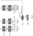
Fig. 3 is a flow diagram illustrating a method of analysing and filtering the data output from an array of sensors in accordance with an embodiment of the present invention; and -
Fig. 4 shows a system for preventing instability in a vehicle-trailer combination according to an embodiment of the present invention. - Referring to
Fig. 1A , a vehicle-trailer combination 10 comprises avehicle 20 towing an attachedtrailer 30. InFig. 1A , the vehicle-trailer combination 10 is in a neutral state where the longitudinal axis Lv of thevehicle 20 is substantially aligned with the longitudinal axis LT of thetrailer 30. In this condition the yaw angle, θ, of thetrailer 30 relative to thevehicle 20 is at or near 0°. - Referring to
Fig. 1B , as thevehicle 20 tows thetrailer 30, there may be a tendency for thetrailer 30 to yaw away from the neutral position represented inFig. 1A thereby resulting in a yaw angle θ which is greater than 0°. This tendency to yaw may result from many factors, for example, the dynamics of lane-change manoeuvres, wind gusts, sharp cornering, adverse cambers etc. Furthermore, in such damped systems, once thetrailer 30 has departed from its neutral position, it will normally tend to return back towards the neutral position; however, once it reaches the neutral position its momentum will also cause it to pass through the neutral position in a pendulum effect which results in a swaying motion of thetrailer 30 relative to thevehicle 20. The rate at which thetrailer 30 moves between a yawed position on one side of thevehicle 20 to an opposite yaw position on the other side of thevehicle 20 is the yaw frequency. - In the presently described embodiment, movement of the
trailer 30 relative to the towingvehicle 20 is sensed by optical sensing means and, more specifically, by an optical sensor such as a rearward facing camera mounted on thevehicle 20. In the case that thevehicle 20 is provided with one or more rearward facing parking assist cameras, these may be employed for the purpose of sensing movement of the trailer, advantageously obviating the need for an additional camera. Additionally, in the present embodiment, the relative movement of the trailer is also detected using ultrasonic sensors, which may conveniently be existing park-assist sensors mounted on the rear of thevehicle 20. Thus, advantageously, the trailer yaw angle θ, i.e. the deviation of thetrailer 30 away from the neutral position, is detected by contactless sensors on-board the vehicle. This has the advantage that the sensors are not subjected to any mechanical wear and tear. In further embodiments of the present invention, other types of sensing means may be employed to detect the relative movement between thevehicle 20 andtrailer 30 e.g. radar and/or a mechanical arrangement provided at the trailer hitch point such as an encoder wheel arrangement. - Referring to
Figs. 2A and 2B , a method of determining the yaw angle of the trailer's longitudinal axis LT relative to the vehicle's longitudinal axis Lv using a rearward facing camera mounted on the vehicle will now be described. - As shown in
Fig. 2A , a registration process may be first undertaken by the driver in order to ascertain the dimensions of the trailer edges as viewed by the camera. Although these relative dimensions may be input manually into the system by the driver if desired, the camera can instead be used to register these dimensions automatically based on the image viewed. In the embodiment shown, the dimensions registered are edges A, B, C and D of thetrailer 30; however, it will be appreciated that any other dimensions oftrailer 30 could instead be registered as desired. - As shown in
Fig. 2B , as thetrailer 30 departs from the neutral position in a yawing movement, the dimensions of edges A', B', C', D' of thetrailer 30 viewed by the camera will change relative to those that were viewed by the camera when the trailer was in the neutral position. This change in the relative dimensions viewed by the camera can be readily correlated to the change in yaw angle θ of the trailer relative to the vehicle. This effect is amplified by the proximity of the rearward facing camera to the trailer since even relatively small angular movements will result in significant changes in the relative dimensions of the trailer perceived by the camera. For example, as the yaw angle of thetrailer 30 increases, the upper and lower side edges B', D' on the right-hand side of the trailer (as viewed by the camera) appear to be lengthened as compared to how they appear inFig. 2A . Similarly, the corresponding upper and lower side edges on the left-hand side of thetrailer 30, appear shortened inFig. 2B compared to how they appear inFig. 2A . - The above method of determining the trailer yaw angle is based upon a comparison of relative perceived dimensions of the
trailer 30. Therefore, it may not be necessary to perform the registration when thetrailer 30 is in the neutral position but may instead be possible to perform the registration procedure when thetrailer 30 is at any initial angle relative to thevehicle 20. - In the present embodiment, more than one camera may be provided, and in addition to the camera(s), the
vehicle 20 is also provided with additional sensors, such as ultrasonic sensors, which also detect a value for the yaw angle θ of thetrailer 30. In the case that the ultrasonic sensors are existing park-assist sensors mounted on the vehicle, such sensors are typically deployed at spaced locations across the rear of the vehicle, e.g. at respective positions along a rear bumper of the vehicle. Each ultrasonic sensor may therefore be used to detect changes in the distance to an adjacent portion of thetrailer 30 as the trailer oscillates from side to side about the neutral position. In more detail, as thetrailer 30 yaws to one side, an ultrasonic sensor disposed on one side of the hitch point detects that an adjacent portion of the trailer is getting closer to the vehicle, whereas an ultrasonic sensor disposed on the opposite side of the hitch point detects thetrailer 30 is getting further away. When thetrailer 30 yaws in the opposite direction, the reverse is true. - The respective signals output from the camera and the ultrasonic sensors each provide a means for measuring the yaw angle of the trailer and these measurements of the yaw angle are input to processing means which performs the filtering and analysis method of
Fig. 3 . - Referring to
Figure 4 , a system for preventing instability in a vehicle-trailer combination comprises processing means in the form of aprocessor 50, a rearward facingcamera 60 mounted on the vehicle,ultrasonic sensors processor 50 may be incorporated in an electronic control unit (ECU) of thevehicle 20 or it may be a separate processor. Each of thecamera 60 and theultrasonic sensors processor 50 such that the signals output from each of thesensors processor 50, and theprocessor 50 is operable to convert the received signals into respective measurements of the yaw angle of thetrailer 30. As explained above, the signal from thecamera 60 can be used to determine the yaw angle of thetrailer 30 by means of the measured change in dimensions of thetrailer 30 compared to a reference image. The signals from theultrasonic sensors sensor - As shown in
Fig. 3 , the raw yaw reading output from a first sensor, i.e. thecamera 60, is provided to theprocessor 50 as θr1. The raw yaw reading output from a second sensor, i.e. the ultrasonic sensor/s 70a, 70b, is provided as θr2. It should be noted that the method and system of the present invention may utilise/include any number of sensors suitable for measuring relative movement between thevehicle 20 andtrailer 30 such that a measurement of the trailer yaw angle can be derived from the signal output therefrom. This is represented by θrN inFig. 3 . - Although a number of methods may be used to process the raw yaw outputs from the various sensors, referring to step A in
Fig. 3 , in the present embodiment this is achieved by performing a Fourier Transform analysis in order to isolate the element of interest in the received signal. In more detail, the yaw angle measured by, for example, thecamera 60, will typically comprise a sinusoidal wavetrace which is characteristic of thetrailer 30 repeatedly swaying to one side of the neutral position and then the other. However, the signal may also comprise unwanted elements, such as noise. Accordingly, the Fourier Transform analysis of the signal allows the various components which make up the signal to be isolated. This then allows any noise components to be filtered out so as to provide a sinusoidal waveform with the noise elements filtered out. The result is output from Step A as filtered yaw readings θ1, θ2, θN. - At step B, the resulting filtered yaw readings are input into a weighting step where sensor weight factors W1, W2, ... WN are calculated. The combined weightings for each sensor all add to 1, i.e. W1 + W2 .... + Wn = 1. For example, in the presently described system having one yaw angle measurement based on the camera signal and one measurement based on the ultrasonic sensors this would be determined as Wcamera + Wultrasonic = 1.
- In a variation of the above-described method, the signal/noise ratio of the received sensor signals may be compared in order to identify which signal is to be given the higher weighting, i.e. a signal with a lesser s/n ratio may be given a lower weighting than a less 'noisy' signal.
- Furthermore, an example of where one reading may be given a higher weighting than another would be where there is a large discrepancy in the returned signals from the various sensors. This might occur when the input from the camera is obscured by fog, dust or darkness etc. in which case the camera will be given a relatively lower weighting than the ultrasonic sensor.
- The yaw angle θt at any given time is then calculated as

- The resulting filtered and weighted yaw angle measured θt is then compared at Step C with a predetermined critical yaw angle θc. If θt is less than θc the system is determined as being stable and no warning is given; however, if θt is greater than θc the system has identified the onset of an unstable condition which could lead to an oscillation. In this scenario an appropriate warning is issued to the driver via the
HMI 80 at Step D to take corrective action. The warning sent to the driver at Step D could be an audible or visual warning such as a warning light on the instrument dashboard. The decision on what form of corrective action is required may be left to the driver; however, it will normally involve easing off the accelerator or gently applying the brakes. Indeed, different types of warning may be provided depending upon the severity of the situation and these warnings may include suggestions to the driver on the best course of action. For example, a warning sign or symbol could be displayed recommending that the driver applies the brakes or that the driver releases the accelerator, and/or steers the vehicle in a particular direction. - In the above-described example, the yaw condition of the
trailer 30 which is determined from the signal output by the various sensors is the yaw angle. However, other parameters may be monitored by the system in a similar way. One particular variable which could also be simultaneously detected by the same sensors is the yaw frequency of the trailer. This can further facilitate early detection of an instability condition. This is because particular frequency modes can mean an increased likelihood of critical instability developing regardless of the magnitude of angular displacement of thetrailer 30 relative thevehicle 20. In other words, a small angular sway at the correct frequency can be dangerous even if the magnitude of the sway is not. Accordingly, in a variation of the above-described embodiment, theprocessor 50 is operable to determine the yaw frequency of thetrailer 30 based on each of the signals output from the respective sensors. A weighted yaw frequency may be calculated by applying weightings to the measurements from each of the various sensors in the same way as described previously. The weighted yaw frequency may then be compared to a threshold frequency, which is characteristic of the onset of instability in the vehicle-trailer combination and, in the event that the threshold is exceeded, an alert signal may be output to theHMI 80 to warn the driver to take corrective measures. In a yet further embodiment of the present invention, theprocessor 50 may be operable to determine both a weighted yaw angle and a weighted yaw frequency from the sensor signals and to compared the determined angle and frequency values to respective thresholds, the alert signal being output in dependence on one or both of the thresholds being exceeded by the determined values. - The previously described system detects the onset of oscillations in the vehicle-trailer system at a very early stage thereby allowing action to be taken by the driver to prevent the oscillation developing further. Furthermore, this can be used to allow the driver to determine an optimum driving speed (one at which the warning does not activate) thereby minimising the need for braking.
- In the embodiment of the invention described above, the primary output from the system is a warning given directly to the driver in order to allow the driver to take the required corrective action; however, in an alternative embodiment of the invention, the alert signal output from the system may be input into the vehicle's existing ESC system. This allows the ESC to automatically take corrective action on behalf of the driver. This approach has an advantage over existing systems in that over-braking of the vehicle wheels may be avoided. This is because a system operating in accordance with this embodiment of the invention directly monitors the movement of the trailer such that the alert signal is output to the ESC at a much earlier stage and therefore corrective action may be taken earlier to prevent instability from occurring. For example, this could mean that upon detecting the early onset of oscillation, the ESC system automatically eases off the accelerator without having to apply the vehicle's brakes in order to regulate the vehicle-trailer road speed.
- In contrast, with a system in which the ESC is responsive to the output of gyroscopic yaw sensors disposed on the vehicle, it may be the case that, by the time the yaw sensors detect significant yaw of the vehicle for the ESC to instigate corrective measures, the oscillations of the trailer are such that it is too late to stop a critical instability from developing.
- The following numbered clauses define various further aspects and features of the present technique:
- 1. A method of preventing instability in a vehicle-trailer combination, the method comprising;
monitoring relative movement between the vehicle and the trailer using optical sensing means;
determining a trailer yaw condition in dependence on a signal output from the optical sensing means;
comparing the determined trailer yaw condition to a predetermined threshold yaw condition; and
when the determined trailer yaw condition is equal to or greater than the predetermined threshold yaw condition, outputting an alert signal indicative of the onset of instability in the vehicle-trailer combination. - 2. A method according to
clause 1, comprising outputting the alert signal directly to the driver of a vehicle in order to allow the driver to take corrective measures. - 3. A method according to
clause 1, comprising outputting the alert signal to an electronic stability system of the vehicle in order to allow the electronic stability system to take corrective measures. - 4. A method according to any preceding clause, wherein the step of determining a trailer yaw condition comprises determining one or both of a trailer yaw angle and a trailer yaw frequency.
- 5. A method according to any preceding clause, comprising determining the trailer yaw condition in dependence on a signal output from at least one further sensing means.
- 6. A method according to clause 5, wherein determining the trailer yaw condition comprises performing a Fourier Transform analysis of the respective signals output from said optical sensing means and said at least one further sensing means.
- 7. A method according to clause 5 or clause 6, comprising determining the trailer yaw condition in dependence on a weighting factor associated with each of the optical sensing means and said at least one further sensing means, the weighting factor being indicative of the expected accuracy with which the trailer yaw condition can be determined using the optical sensing means and the at least one further sensing means, respectively, a higher weighting factor being associated with a greater expected accuracy.
- 8. A method according to any one of clauses 5 to 7, wherein said at least one further sensing means is a contactless sensor.
- 9. A method according to clause 8, wherein said at least one further sensing means comprises an ultrasonic sensor or a radar sensor.
- 10. A method according to any one of clauses, 5 to 7, wherein said at least one further sensing means comprises an encoder arrangement.
- 11. A method according to
clause 10, wherein the encoder arrangement comprises a rotary encoder disposed at a trailer hitch point. - 12. A method according to any preceding clause, wherein the optical sensing means comprises a camera.
- 13. A method according to clause 12, comprising capturing a reference image of the trailer using the camera, monitoring the trailer during towing using the camera, and determining the trailer yaw condition based on differences between a monitored image of the trailer and the reference image.
- 14. A method according to clause 13, wherein determining the trailer yaw condition comprises registering the relative dimensions of at least a portion of the trailer, as viewed by the camera in a neutral condition, and comparing those registered relative dimensions to those viewed by the camera during towing of the trailer in order to determine the yaw condition.
- 15. A method of preventing instability in a vehicle-trailer combination, the method comprising;
sensing relative movement between the vehicle and the trailer using first and second sensors;
outputting a signal from each of the first and second sensors;
determining first and second trailer yaw conditions in dependence on respective signals from the first and second sensors;
applying a weighting factor to each of the first and second trailer yaw conditions in dependence on the expected accuracy of the respective first and second sensors, a higher weighting factor being associated with a greater expected accuracy; and
determining a composite trailer yaw condition in dependence on the weighted first and second trailer yaw conditions;
comparing the determined composite trailer yaw condition to a predetermined threshold yaw condition; and
when the determined composite trailer yaw condition is equal to or greater than the predetermined threshold yaw condition, outputting an alert signal indicative of the onset of instability in the vehicle-trailer combination. - 16. A method according to clause 15, comprising outputting the alert signal directly to the driver of a vehicle in order to allow the driver to take corrective measures.
- 17. A method according to clause 15, comprising outputting the alert signal to an electronic stability system of the vehicle in order to allow the electronic stability system to take corrective measures.
- 18. A method according to any one of clauses 15 to 17, wherein the step of determining the first and second trailer yaw conditions comprises determining one or both of a trailer yaw angle and a trailer yaw frequency.
- 19. A method according to any one of clauses 15 to 18, wherein determining the first and second trailer yaw conditions comprises performing a Fourier Transform analysis of the respective signals output from the first and second sensors.
- 20. A method according to any one of clauses 15 to 19, wherein the first and second sensors are one of an optical sensor, an ultrasonic sensor, a radar sensor and an encoder arrangement.
- 21. A method according to any
clause 20, wherein the first sensor comprises a camera. - 22. A method according to clause 21, comprising capturing a reference image of the trailer using the camera, monitoring the trailer during towing using the camera, and determining the trailer yaw condition based on differences between a monitored image of the trailer and the reference image.
- 23. A method according to clause 22, wherein determining the trailer yaw condition comprises registering the relative dimensions of at least a portion of the trailer, as viewed by the camera in a neutral condition, and comparing those registered relative dimensions to those viewed by the camera during towing of the trailer in order to determine the yaw condition.
- 24. A computer program stored in a memory, such that when a processor of a vehicle is programmed by the computer program, the processor is adapted to perform the method of any one of
clauses 1 to 14. - 25. A system for preventing instability in a vehicle-trailer combination, the system comprising;
optical sensing means disposed on the vehicle for sensing relative movement between the vehicle and the trailer;
a controller having a processor and a memory;
wherein the memory contains a computer program according to clause 24, and wherein the processor is programmed to control the system to perform the method of any one ofclauses 1 to 14. - 26. A computer program stored in a memory, such that when a processor of a vehicle is programmed by the computer program, the processor is adapted to perform the method of any one of clauses 15 to 23.
- 27. A system for preventing instability in a vehicle-trailer combination, the system comprising;
first and second sensors disposed on the vehicle for sensing relative movement between the vehicle and the trailer;
a controller having a processor and a memory;
wherein the memory contains a computer program according to clause 26, and wherein the processor is programmed to control the system to perform the method of any one of clauses 15 to 23. - 28. A vehicle operating in accordance with the method of any one of
clauses 1 to 23 or having the system of clause 25 or clause 27.
Claims (13)
- A method of preventing instability in a vehicle-trailer combination, the method comprising;
monitoring relative movement between the vehicle and the trailer using optical sensing means, wherein the optical sensing means comprises a camera;
determining a trailer yaw condition in dependence on a signal output from the optical sensing means;
comparing the determined trailer yaw condition to a predetermined threshold yaw condition; and
when the determined trailer yaw condition is equal to or greater than the predetermined threshold yaw condition, outputting an alert signal indicative of the onset of instability in the vehicle-trailer combination directly to a driver of the vehicle in order to allow the driver to take corrective measures, wherein the method comprises capturing a reference image of the trailer using the camera, monitoring the trailer during towing using the camera, and determining the trailer yaw condition based on differences between a monitored image of the trailer and the reference image. - A method according to claim 1, wherein the step of determining a trailer yaw condition comprises determining one or both of a trailer yaw angle and a trailer yaw frequency.
- A method according to claim 1 or claim 2, comprising determining the trailer yaw condition in dependence on a signal output from at least one further sensing means.
- A method according to claim 3, wherein determining the trailer yaw condition comprises performing a Fourier Transform analysis of the respective signals output from said optical sensing means and said at least one further sensing means.
- A method according to claim 3 or claim 4, comprising determining the trailer yaw condition in dependence on a weighting factor associated with each of the optical sensing means and said at least one further sensing means, the weighting factor being indicative of the expected accuracy with which the trailer yaw condition can be determined using the optical sensing means and the at least one further sensing means, respectively, a higher weighting factor being associated with a greater expected accuracy.
- A method according to any one of claims 3 to 5, wherein said at least one further sensing means is a contactless sensor.
- A method according to claim 6, wherein said at least one further sensing means comprises an ultrasonic sensor or a radar sensor.
- A method according to any one of claims 3 to 5, wherein said at least one further sensing means comprises an encoder arrangement.
- A method according to claim 8, wherein the encoder arrangement comprises a rotary encoder disposed at a trailer hitch point.
- A method according to any preceding claim, wherein determining the trailer yaw condition comprises registering the relative dimensions of at least a portion of the trailer, as viewed by the camera in a neutral condition, and comparing those registered relative dimensions to those viewed by the camera during towing of the trailer in order to determine the yaw condition.
- A computer program stored in a memory, such that when a processor of a vehicle is programmed by the computer program, the processor is adapted to perform the method of any one of claims 1 to 10.
- A system for preventing instability in a vehicle-trailer combination, the system comprising;
optical sensing means disposed on the vehicle for sensing relative movement between the vehicle and the trailer;
a controller having a processor and a memory;
wherein the memory contains a computer program as claimed in claim 11, and wherein the processor is programmed to control the system to perform the method of any one of claims 1 to 10. - A vehicle operating in accordance with the method of any one of claims 1 to 10 or having the system of claim 12.
Applications Claiming Priority (3)
| Application Number | Priority Date | Filing Date | Title |
|---|---|---|---|
| GB1215900.0A GB2505666B (en) | 2012-09-06 | 2012-09-06 | Method and system for preventing instability in a vehicle-trailer combination |
| PCT/EP2013/068465 WO2014037500A1 (en) | 2012-09-06 | 2013-09-06 | Method and system for preventing instability in a vehicle-trailer combination |
| EP13760020.1A EP2892738B1 (en) | 2012-09-06 | 2013-09-06 | Method and system for preventing instability in a vehicle-trailer combination |
Related Parent Applications (1)
| Application Number | Title | Priority Date | Filing Date |
|---|---|---|---|
| EP13760020.1A Division EP2892738B1 (en) | 2012-09-06 | 2013-09-06 | Method and system for preventing instability in a vehicle-trailer combination |
Publications (2)
| Publication Number | Publication Date |
|---|---|
| EP3587148A1 true EP3587148A1 (en) | 2020-01-01 |
| EP3587148B1 EP3587148B1 (en) | 2022-04-06 |
Family
ID=47137021
Family Applications (2)
| Application Number | Title | Priority Date | Filing Date |
|---|---|---|---|
| EP19188625.8A Active EP3587148B1 (en) | 2012-09-06 | 2013-09-06 | Method and system for preventing instability in a vehicle-trailer combination |
| EP13760020.1A Active EP2892738B1 (en) | 2012-09-06 | 2013-09-06 | Method and system for preventing instability in a vehicle-trailer combination |
Family Applications After (1)
| Application Number | Title | Priority Date | Filing Date |
|---|---|---|---|
| EP13760020.1A Active EP2892738B1 (en) | 2012-09-06 | 2013-09-06 | Method and system for preventing instability in a vehicle-trailer combination |
Country Status (4)
| Country | Link |
|---|---|
| US (1) | US9555813B2 (en) |
| EP (2) | EP3587148B1 (en) |
| GB (2) | GB2522105B (en) |
| WO (1) | WO2014037500A1 (en) |
Families Citing this family (77)
| Publication number | Priority date | Publication date | Assignee | Title |
|---|---|---|---|---|
| GB2447672B (en) | 2007-03-21 | 2011-12-14 | Ford Global Tech Llc | Vehicle manoeuvring aids |
| US9434414B2 (en) | 2011-04-19 | 2016-09-06 | Ford Global Technologies, Llc | System and method for determining a hitch angle offset |
| US9555832B2 (en) | 2011-04-19 | 2017-01-31 | Ford Global Technologies, Llc | Display system utilizing vehicle and trailer dynamics |
| US10196088B2 (en) | 2011-04-19 | 2019-02-05 | Ford Global Technologies, Llc | Target monitoring system and method |
| US9969428B2 (en) | 2011-04-19 | 2018-05-15 | Ford Global Technologies, Llc | Trailer backup assist system with waypoint selection |
| US9937953B2 (en) | 2011-04-19 | 2018-04-10 | Ford Global Technologies, Llc | Trailer backup offset determination |
| US9335163B2 (en) | 2011-04-19 | 2016-05-10 | Ford Global Technologies, Llc | Trailer length estimation in hitch angle applications |
| US9854209B2 (en) | 2011-04-19 | 2017-12-26 | Ford Global Technologies, Llc | Display system utilizing vehicle and trailer dynamics |
| US9290203B2 (en) | 2011-04-19 | 2016-03-22 | Ford Global Technologies, Llc | Trailer length estimation in hitch angle applications |
| US9513103B2 (en) | 2011-04-19 | 2016-12-06 | Ford Global Technologies, Llc | Hitch angle sensor assembly |
| US9500497B2 (en) | 2011-04-19 | 2016-11-22 | Ford Global Technologies, Llc | System and method of inputting an intended backing path |
| US9683848B2 (en) | 2011-04-19 | 2017-06-20 | Ford Global Technologies, Llc | System for determining hitch angle |
| US9926008B2 (en) | 2011-04-19 | 2018-03-27 | Ford Global Technologies, Llc | Trailer backup assist system with waypoint selection |
| US9290204B2 (en) | 2011-04-19 | 2016-03-22 | Ford Global Technologies, Llc | Hitch angle monitoring system and method |
| US9290202B2 (en) | 2011-04-19 | 2016-03-22 | Ford Global Technologies, Llc | System and method of calibrating a trailer backup assist system |
| US9506774B2 (en) | 2011-04-19 | 2016-11-29 | Ford Global Technologies, Llc | Method of inputting a path for a vehicle and trailer |
| US9374562B2 (en) | 2011-04-19 | 2016-06-21 | Ford Global Technologies, Llc | System and method for calculating a horizontal camera to target distance |
| US9373044B2 (en) | 2011-07-25 | 2016-06-21 | Ford Global Technologies, Llc | Trailer lane departure warning system |
| US9187124B2 (en) * | 2012-04-10 | 2015-11-17 | Ford Global Technologies | Steering input apparatus for trailer backup assist system |
| US9511799B2 (en) | 2013-02-04 | 2016-12-06 | Ford Global Technologies, Llc | Object avoidance for a trailer backup assist system |
| US9592851B2 (en) | 2013-02-04 | 2017-03-14 | Ford Global Technologies, Llc | Control modes for a trailer backup assist system |
| US9352777B2 (en) | 2013-10-31 | 2016-05-31 | Ford Global Technologies, Llc | Methods and systems for configuring of a trailer maneuvering system |
| GB2523097B (en) * | 2014-02-12 | 2016-09-28 | Jaguar Land Rover Ltd | Vehicle terrain profiling system with image enhancement |
| US9233710B2 (en) | 2014-03-06 | 2016-01-12 | Ford Global Technologies, Llc | Trailer backup assist system using gesture commands and method |
| US9440627B2 (en) * | 2014-05-28 | 2016-09-13 | Toyota Motor Engineering & Manufacturing North America, Inc. | Systems and methods for calculating trailer brake control parameters |
| US9517668B2 (en) | 2014-07-28 | 2016-12-13 | Ford Global Technologies, Llc | Hitch angle warning system and method |
| US9963004B2 (en) | 2014-07-28 | 2018-05-08 | Ford Global Technologies, Llc | Trailer sway warning system and method |
| US9315212B1 (en) | 2014-10-13 | 2016-04-19 | Ford Global Technologies, Llc | Trailer sensor module and associated method of wireless trailer identification and motion estimation |
| US9340228B2 (en) | 2014-10-13 | 2016-05-17 | Ford Global Technologies, Llc | Trailer motion and parameter estimation system |
| US9522677B2 (en) | 2014-12-05 | 2016-12-20 | Ford Global Technologies, Llc | Mitigation of input device failure and mode management |
| US9533683B2 (en) | 2014-12-05 | 2017-01-03 | Ford Global Technologies, Llc | Sensor failure mitigation system and mode management |
| US9607242B2 (en) | 2015-01-16 | 2017-03-28 | Ford Global Technologies, Llc | Target monitoring system with lens cleaning device |
| US9522699B2 (en) | 2015-02-05 | 2016-12-20 | Ford Global Technologies, Llc | Trailer backup assist system with adaptive steering angle limits |
| GB2535789B (en) | 2015-02-27 | 2019-05-29 | Jaguar Land Rover Ltd | Trailer tracking apparatus and method |
| US9616923B2 (en) | 2015-03-03 | 2017-04-11 | Ford Global Technologies, Llc | Topographical integration for trailer backup assist system |
| US9804022B2 (en) | 2015-03-24 | 2017-10-31 | Ford Global Technologies, Llc | System and method for hitch angle detection |
| US9896130B2 (en) | 2015-09-11 | 2018-02-20 | Ford Global Technologies, Llc | Guidance system for a vehicle reversing a trailer along an intended backing path |
| US10611407B2 (en) | 2015-10-19 | 2020-04-07 | Ford Global Technologies, Llc | Speed control for motor vehicles |
| US10384607B2 (en) | 2015-10-19 | 2019-08-20 | Ford Global Technologies, Llc | Trailer backup assist system with hitch angle offset estimation |
| US9836060B2 (en) | 2015-10-28 | 2017-12-05 | Ford Global Technologies, Llc | Trailer backup assist system with target management |
| US10017115B2 (en) | 2015-11-11 | 2018-07-10 | Ford Global Technologies, Llc | Trailer monitoring system and method |
| US10155478B2 (en) | 2015-12-17 | 2018-12-18 | Ford Global Technologies, Llc | Centerline method for trailer hitch angle detection |
| US9827818B2 (en) | 2015-12-17 | 2017-11-28 | Ford Global Technologies, Llc | Multi-stage solution for trailer hitch angle initialization |
| US9610975B1 (en) | 2015-12-17 | 2017-04-04 | Ford Global Technologies, Llc | Hitch angle detection for trailer backup assist system |
| US9798953B2 (en) | 2015-12-17 | 2017-10-24 | Ford Global Technologies, Llc | Template matching solution for locating trailer hitch point |
| US10011228B2 (en) | 2015-12-17 | 2018-07-03 | Ford Global Technologies, Llc | Hitch angle detection for trailer backup assist system using multiple imaging devices |
| US9796228B2 (en) | 2015-12-17 | 2017-10-24 | Ford Global Technologies, Llc | Hitch angle detection for trailer backup assist system |
| US10005492B2 (en) | 2016-02-18 | 2018-06-26 | Ford Global Technologies, Llc | Trailer length and hitch angle bias estimation |
| US10112646B2 (en) | 2016-05-05 | 2018-10-30 | Ford Global Technologies, Llc | Turn recovery human machine interface for trailer backup assist |
| US10106193B2 (en) | 2016-07-01 | 2018-10-23 | Ford Global Technologies, Llc | Enhanced yaw rate trailer angle detection initialization |
| US10046800B2 (en) | 2016-08-10 | 2018-08-14 | Ford Global Technologies, Llc | Trailer wheel targetless trailer angle detection |
| US20180068566A1 (en) * | 2016-09-08 | 2018-03-08 | Delphi Technologies, Inc. | Trailer lane departure warning and sway alert |
| US10222804B2 (en) | 2016-10-21 | 2019-03-05 | Ford Global Technologies, Llc | Inertial reference for TBA speed limiting |
| EP3379222B1 (en) | 2017-03-22 | 2020-12-30 | Methode Electronics Malta Ltd. | Magnetoelastic based sensor assembly |
| US10710585B2 (en) | 2017-09-01 | 2020-07-14 | Ford Global Technologies, Llc | Trailer backup assist system with predictive hitch angle functionality |
| DE102017123328B4 (en) * | 2017-10-09 | 2020-07-23 | Saf-Holland Gmbh | Yaw angle measuring device |
| US10955540B2 (en) | 2017-12-01 | 2021-03-23 | Aptiv Technologies Limited | Detection system |
| WO2019168565A1 (en) | 2018-02-27 | 2019-09-06 | Methode Electronics,Inc. | Towing systems and methods using magnetic field sensing |
| US11135882B2 (en) | 2018-02-27 | 2021-10-05 | Methode Electronics, Inc. | Towing systems and methods using magnetic field sensing |
| US11014417B2 (en) | 2018-02-27 | 2021-05-25 | Methode Electronics, Inc. | Towing systems and methods using magnetic field sensing |
| US11221262B2 (en) | 2018-02-27 | 2022-01-11 | Methode Electronics, Inc. | Towing systems and methods using magnetic field sensing |
| US11491832B2 (en) | 2018-02-27 | 2022-11-08 | Methode Electronics, Inc. | Towing systems and methods using magnetic field sensing |
| US11084342B2 (en) | 2018-02-27 | 2021-08-10 | Methode Electronics, Inc. | Towing systems and methods using magnetic field sensing |
| US11731471B2 (en) * | 2018-04-27 | 2023-08-22 | Fontaine Fifth Wheel Company | Methods and systems for monitoring coupling of fifth wheels to kingpins |
| JP7147300B2 (en) | 2018-07-05 | 2022-10-05 | 株式会社アイシン | Traction support device |
| US10838054B2 (en) | 2018-10-08 | 2020-11-17 | Aptiv Technologies Limited | Detection system and method |
| US11077795B2 (en) | 2018-11-26 | 2021-08-03 | Ford Global Technologies, Llc | Trailer angle detection using end-to-end learning |
| US11092668B2 (en) | 2019-02-07 | 2021-08-17 | Aptiv Technologies Limited | Trailer detection system and method |
| US11524536B2 (en) | 2019-02-14 | 2022-12-13 | Fontaine Fifth Wheel Company | Apparatuses, systems, and methods for determining and verifying operational states of fifth wheels |
| US10829046B2 (en) | 2019-03-06 | 2020-11-10 | Ford Global Technologies, Llc | Trailer angle detection using end-to-end learning |
| DE102019205321A1 (en) | 2019-04-12 | 2020-10-15 | Deere & Company | Method for controlling the operation of an attachment |
| DE102019003207A1 (en) | 2019-05-07 | 2020-11-12 | Deere & Company | Coupling device for a power lift |
| US11285768B2 (en) * | 2019-08-07 | 2022-03-29 | Ford Global Technologies, Llc | Vehicle system and method for detecting trailer connection |
| DE102019213746A1 (en) | 2019-09-10 | 2021-03-11 | Deere & Company | Method for controlling the operation of an attachment |
| FR3106432B1 (en) * | 2020-01-21 | 2021-12-10 | Continental Automotive | System for determining the angular position of a trailer |
| US11408995B2 (en) | 2020-02-24 | 2022-08-09 | Aptiv Technologies Limited | Lateral-bin monitoring for radar target detection |
| EP4177122A1 (en) * | 2021-11-08 | 2023-05-10 | Volvo Truck Corporation | A system and a method for probing properties of a trailer towed by a towing vehicle in a heavy-duty vehicle combination |
Citations (5)
| Publication number | Priority date | Publication date | Assignee | Title |
|---|---|---|---|---|
| EP1593552A1 (en) * | 2004-05-05 | 2005-11-09 | Robert Bosch Gmbh | System and method for monitoring a car trailer |
| GB2447672A (en) * | 2007-03-21 | 2008-09-24 | Ford Global Tech Llc | Vehicle manoeuvring aids |
| EP2045155A1 (en) * | 2007-10-05 | 2009-04-08 | Ford Global Technologies, LLC | A control system for a vehicle and trailer combination |
| US20090198425A1 (en) * | 2008-02-06 | 2009-08-06 | Ford Global Technologies, Llc | Trailer sway control with reverse sensors |
| EP2436540A1 (en) * | 2010-10-04 | 2012-04-04 | Jtekt Europe | Assembly for determining the angular position of a towed vehicle relative to a towing vehicle |
Family Cites Families (7)
| Publication number | Priority date | Publication date | Assignee | Title |
|---|---|---|---|---|
| DE19901953B4 (en) * | 1999-01-20 | 2014-02-06 | Robert Bosch Gmbh | Device and method for stabilizing a vehicle combination |
| US6959970B2 (en) * | 2004-03-18 | 2005-11-01 | Ford Global Technologies, Llc | Method and apparatus for controlling a trailer and an automotive vehicle with a yaw stability control system |
| US7904222B2 (en) * | 2007-06-27 | 2011-03-08 | GM Global Technology Operations LLC | Trailer articulation angle estimation |
| US7917274B2 (en) * | 2007-10-19 | 2011-03-29 | Advics Co., Ltd. | Method and apparatus for vehicle sway detection and reduction |
| US8060288B2 (en) * | 2009-03-20 | 2011-11-15 | Toyota Motor Engineering & Manufacturing North America, Inc. | Control system and method to inhibit automatic transmission downshifting during trailer sway |
| US20110087402A1 (en) * | 2009-10-14 | 2011-04-14 | Continental Teves, Inc. | Detection of Trailer Sway Utilizing Park Assist Sensors |
| US8532897B2 (en) * | 2011-12-15 | 2013-09-10 | Bendix Commercial Vehicle Systems Llc | Controller and method for detecting vehicle pull |
-
2012
- 2012-09-06 GB GB1419825.3A patent/GB2522105B/en not_active Expired - Fee Related
- 2012-09-06 GB GB1215900.0A patent/GB2505666B/en active Active
-
2013
- 2013-09-06 US US14/426,190 patent/US9555813B2/en active Active
- 2013-09-06 EP EP19188625.8A patent/EP3587148B1/en active Active
- 2013-09-06 WO PCT/EP2013/068465 patent/WO2014037500A1/en active Application Filing
- 2013-09-06 EP EP13760020.1A patent/EP2892738B1/en active Active
Patent Citations (5)
| Publication number | Priority date | Publication date | Assignee | Title |
|---|---|---|---|---|
| EP1593552A1 (en) * | 2004-05-05 | 2005-11-09 | Robert Bosch Gmbh | System and method for monitoring a car trailer |
| GB2447672A (en) * | 2007-03-21 | 2008-09-24 | Ford Global Tech Llc | Vehicle manoeuvring aids |
| EP2045155A1 (en) * | 2007-10-05 | 2009-04-08 | Ford Global Technologies, LLC | A control system for a vehicle and trailer combination |
| US20090198425A1 (en) * | 2008-02-06 | 2009-08-06 | Ford Global Technologies, Llc | Trailer sway control with reverse sensors |
| EP2436540A1 (en) * | 2010-10-04 | 2012-04-04 | Jtekt Europe | Assembly for determining the angular position of a towed vehicle relative to a towing vehicle |
Also Published As
| Publication number | Publication date |
|---|---|
| GB2522105A (en) | 2015-07-15 |
| GB201419825D0 (en) | 2014-12-24 |
| EP2892738B1 (en) | 2019-08-28 |
| GB2522105B (en) | 2016-09-14 |
| GB2505666A (en) | 2014-03-12 |
| EP3587148B1 (en) | 2022-04-06 |
| US9555813B2 (en) | 2017-01-31 |
| EP2892738A1 (en) | 2015-07-15 |
| GB2505666B (en) | 2015-07-01 |
| US20150203128A1 (en) | 2015-07-23 |
| GB201215900D0 (en) | 2012-10-24 |
| WO2014037500A1 (en) | 2014-03-13 |
Similar Documents
| Publication | Publication Date | Title |
|---|---|---|
| EP2892738B1 (en) | Method and system for preventing instability in a vehicle-trailer combination | |
| JP6577480B2 (en) | Method of operating autonomous driving type traveling safety system or driver assistance system of automobile | |
| CN108674412B (en) | Vehicle active collision avoidance method adopting sensor fusion | |
| EP1965993B1 (en) | Method and system for assisting a driver when parking or manoeuvring a motor vehicle | |
| US9310484B2 (en) | Device for detecting a moving object | |
| CN105799617B (en) | Method for the misalignment for determining object sensor | |
| US7904222B2 (en) | Trailer articulation angle estimation | |
| US8930063B2 (en) | Method for determining object sensor misalignment | |
| EP2618108B1 (en) | Driver assisting system | |
| US8280586B2 (en) | Determination of the actual yaw angle and the actual slip angle of a land vehicle | |
| US20060244579A1 (en) | Device and method for determining an orientation of a semitrailer or trailer | |
| US20130124061A1 (en) | System and method for determining a speed of a vehicle | |
| US20130057397A1 (en) | Method of operating a vehicle safety system | |
| US10328933B2 (en) | Cognitive reverse speed limiting | |
| CN111469850A (en) | Method for determining driving dynamics of a commercial vehicle and driver assistance system | |
| CN110576862A (en) | Trailer-based roll control vehicle | |
| US20170263127A1 (en) | Vehicle collision system and method of using the same | |
| GB2543656A (en) | Method for assisting a vehicle-trailer combination and system | |
| CN109070858B (en) | Method and device for determining a safety-critical yaw movement of a vehicle | |
| US20160121892A1 (en) | Method and device for determining a driving state of an external motor vehicle | |
| WO2014177380A1 (en) | Method for predicting instability in a vehicle-trailer combination | |
| JP2017531268A5 (en) | ||
| US8285477B2 (en) | Detection method for preventing automobile from colliding | |
| CN112313140B (en) | Method and system for controlling steering of vehicle | |
| SE1050980A1 (en) | Safety system for a vehicle and method for a safety system |
Legal Events
| Date | Code | Title | Description |
|---|---|---|---|
| STAA | Information on the status of an ep patent application or granted ep patent |
Free format text: STATUS: EXAMINATION IS IN PROGRESS |
|
| PUAI | Public reference made under article 153(3) epc to a published international application that has entered the european phase |
Free format text: ORIGINAL CODE: 0009012 |
|
| 17P | Request for examination filed |
Effective date: 20190726 |
|
| AC | Divisional application: reference to earlier application |
Ref document number: 2892738 Country of ref document: EP Kind code of ref document: P |
|
| AK | Designated contracting states |
Kind code of ref document: A1 Designated state(s): AL AT BE BG CH CY CZ DE DK EE ES FI FR GB GR HR HU IE IS IT LI LT LU LV MC MK MT NL NO PL PT RO RS SE SI SK SM TR |
|
| STAA | Information on the status of an ep patent application or granted ep patent |
Free format text: STATUS: EXAMINATION IS IN PROGRESS |
|
| GRAP | Despatch of communication of intention to grant a patent |
Free format text: ORIGINAL CODE: EPIDOSNIGR1 |
|
| STAA | Information on the status of an ep patent application or granted ep patent |
Free format text: STATUS: GRANT OF PATENT IS INTENDED |
|
| INTG | Intention to grant announced |
Effective date: 20210430 |
|
| GRAS | Grant fee paid |
Free format text: ORIGINAL CODE: EPIDOSNIGR3 |
|
| GRAA | (expected) grant |
Free format text: ORIGINAL CODE: 0009210 |
|
| STAA | Information on the status of an ep patent application or granted ep patent |
Free format text: STATUS: THE PATENT HAS BEEN GRANTED |
|
| AC | Divisional application: reference to earlier application |
Ref document number: 2892738 Country of ref document: EP Kind code of ref document: P |
|
| AK | Designated contracting states |
Kind code of ref document: B1 Designated state(s): AL AT BE BG CH CY CZ DE DK EE ES FI FR GB GR HR HU IE IS IT LI LT LU LV MC MK MT NL NO PL PT RO RS SE SI SK SM TR |
|
| REG | Reference to a national code |
Ref country code: GB Ref legal event code: FG4D |
|
| REG | Reference to a national code |
Ref country code: CH Ref legal event code: EP |
|
| REG | Reference to a national code |
Ref country code: AT Ref legal event code: REF Ref document number: 1481006 Country of ref document: AT Kind code of ref document: T Effective date: 20220415 |
|
| REG | Reference to a national code |
Ref country code: IE Ref legal event code: FG4D |
|
| REG | Reference to a national code |
Ref country code: DE Ref legal event code: R096 Ref document number: 602013081370 Country of ref document: DE |
|
| REG | Reference to a national code |
Ref country code: LT Ref legal event code: MG9D |
|
| REG | Reference to a national code |
Ref country code: NL Ref legal event code: MP Effective date: 20220406 |
|
| REG | Reference to a national code |
Ref country code: AT Ref legal event code: MK05 Ref document number: 1481006 Country of ref document: AT Kind code of ref document: T Effective date: 20220406 |
|
| PG25 | Lapsed in a contracting state [announced via postgrant information from national office to epo] |
Ref country code: NL Free format text: LAPSE BECAUSE OF FAILURE TO SUBMIT A TRANSLATION OF THE DESCRIPTION OR TO PAY THE FEE WITHIN THE PRESCRIBED TIME-LIMIT Effective date: 20220406 |
|
| PG25 | Lapsed in a contracting state [announced via postgrant information from national office to epo] |
Ref country code: SE Free format text: LAPSE BECAUSE OF FAILURE TO SUBMIT A TRANSLATION OF THE DESCRIPTION OR TO PAY THE FEE WITHIN THE PRESCRIBED TIME-LIMIT Effective date: 20220406 Ref country code: PT Free format text: LAPSE BECAUSE OF FAILURE TO SUBMIT A TRANSLATION OF THE DESCRIPTION OR TO PAY THE FEE WITHIN THE PRESCRIBED TIME-LIMIT Effective date: 20220808 Ref country code: NO Free format text: LAPSE BECAUSE OF FAILURE TO SUBMIT A TRANSLATION OF THE DESCRIPTION OR TO PAY THE FEE WITHIN THE PRESCRIBED TIME-LIMIT Effective date: 20220706 Ref country code: LT Free format text: LAPSE BECAUSE OF FAILURE TO SUBMIT A TRANSLATION OF THE DESCRIPTION OR TO PAY THE FEE WITHIN THE PRESCRIBED TIME-LIMIT Effective date: 20220406 Ref country code: HR Free format text: LAPSE BECAUSE OF FAILURE TO SUBMIT A TRANSLATION OF THE DESCRIPTION OR TO PAY THE FEE WITHIN THE PRESCRIBED TIME-LIMIT Effective date: 20220406 Ref country code: GR Free format text: LAPSE BECAUSE OF FAILURE TO SUBMIT A TRANSLATION OF THE DESCRIPTION OR TO PAY THE FEE WITHIN THE PRESCRIBED TIME-LIMIT Effective date: 20220707 Ref country code: FI Free format text: LAPSE BECAUSE OF FAILURE TO SUBMIT A TRANSLATION OF THE DESCRIPTION OR TO PAY THE FEE WITHIN THE PRESCRIBED TIME-LIMIT Effective date: 20220406 Ref country code: ES Free format text: LAPSE BECAUSE OF FAILURE TO SUBMIT A TRANSLATION OF THE DESCRIPTION OR TO PAY THE FEE WITHIN THE PRESCRIBED TIME-LIMIT Effective date: 20220406 Ref country code: BG Free format text: LAPSE BECAUSE OF FAILURE TO SUBMIT A TRANSLATION OF THE DESCRIPTION OR TO PAY THE FEE WITHIN THE PRESCRIBED TIME-LIMIT Effective date: 20220706 Ref country code: AT Free format text: LAPSE BECAUSE OF FAILURE TO SUBMIT A TRANSLATION OF THE DESCRIPTION OR TO PAY THE FEE WITHIN THE PRESCRIBED TIME-LIMIT Effective date: 20220406 |
|
| PG25 | Lapsed in a contracting state [announced via postgrant information from national office to epo] |
Ref country code: RS Free format text: LAPSE BECAUSE OF FAILURE TO SUBMIT A TRANSLATION OF THE DESCRIPTION OR TO PAY THE FEE WITHIN THE PRESCRIBED TIME-LIMIT Effective date: 20220406 Ref country code: PL Free format text: LAPSE BECAUSE OF FAILURE TO SUBMIT A TRANSLATION OF THE DESCRIPTION OR TO PAY THE FEE WITHIN THE PRESCRIBED TIME-LIMIT Effective date: 20220406 Ref country code: LV Free format text: LAPSE BECAUSE OF FAILURE TO SUBMIT A TRANSLATION OF THE DESCRIPTION OR TO PAY THE FEE WITHIN THE PRESCRIBED TIME-LIMIT Effective date: 20220406 Ref country code: IS Free format text: LAPSE BECAUSE OF FAILURE TO SUBMIT A TRANSLATION OF THE DESCRIPTION OR TO PAY THE FEE WITHIN THE PRESCRIBED TIME-LIMIT Effective date: 20220806 |
|
| REG | Reference to a national code |
Ref country code: DE Ref legal event code: R097 Ref document number: 602013081370 Country of ref document: DE |
|
| PG25 | Lapsed in a contracting state [announced via postgrant information from national office to epo] |
Ref country code: SM Free format text: LAPSE BECAUSE OF FAILURE TO SUBMIT A TRANSLATION OF THE DESCRIPTION OR TO PAY THE FEE WITHIN THE PRESCRIBED TIME-LIMIT Effective date: 20220406 Ref country code: SK Free format text: LAPSE BECAUSE OF FAILURE TO SUBMIT A TRANSLATION OF THE DESCRIPTION OR TO PAY THE FEE WITHIN THE PRESCRIBED TIME-LIMIT Effective date: 20220406 Ref country code: RO Free format text: LAPSE BECAUSE OF FAILURE TO SUBMIT A TRANSLATION OF THE DESCRIPTION OR TO PAY THE FEE WITHIN THE PRESCRIBED TIME-LIMIT Effective date: 20220406 Ref country code: EE Free format text: LAPSE BECAUSE OF FAILURE TO SUBMIT A TRANSLATION OF THE DESCRIPTION OR TO PAY THE FEE WITHIN THE PRESCRIBED TIME-LIMIT Effective date: 20220406 Ref country code: DK Free format text: LAPSE BECAUSE OF FAILURE TO SUBMIT A TRANSLATION OF THE DESCRIPTION OR TO PAY THE FEE WITHIN THE PRESCRIBED TIME-LIMIT Effective date: 20220406 Ref country code: CZ Free format text: LAPSE BECAUSE OF FAILURE TO SUBMIT A TRANSLATION OF THE DESCRIPTION OR TO PAY THE FEE WITHIN THE PRESCRIBED TIME-LIMIT Effective date: 20220406 |
|
| PLBE | No opposition filed within time limit |
Free format text: ORIGINAL CODE: 0009261 |
|
| STAA | Information on the status of an ep patent application or granted ep patent |
Free format text: STATUS: NO OPPOSITION FILED WITHIN TIME LIMIT |
|
| 26N | No opposition filed |
Effective date: 20230110 |
|
| PG25 | Lapsed in a contracting state [announced via postgrant information from national office to epo] |
Ref country code: AL Free format text: LAPSE BECAUSE OF FAILURE TO SUBMIT A TRANSLATION OF THE DESCRIPTION OR TO PAY THE FEE WITHIN THE PRESCRIBED TIME-LIMIT Effective date: 20220406 |
|
| PG25 | Lapsed in a contracting state [announced via postgrant information from national office to epo] |
Ref country code: MC Free format text: LAPSE BECAUSE OF FAILURE TO SUBMIT A TRANSLATION OF THE DESCRIPTION OR TO PAY THE FEE WITHIN THE PRESCRIBED TIME-LIMIT Effective date: 20220406 |
|
| REG | Reference to a national code |
Ref country code: CH Ref legal event code: PL |
|
| REG | Reference to a national code |
Ref country code: BE Ref legal event code: MM Effective date: 20220930 |
|
| PG25 | Lapsed in a contracting state [announced via postgrant information from national office to epo] |
Ref country code: SI Free format text: LAPSE BECAUSE OF FAILURE TO SUBMIT A TRANSLATION OF THE DESCRIPTION OR TO PAY THE FEE WITHIN THE PRESCRIBED TIME-LIMIT Effective date: 20220406 |
|
| PG25 | Lapsed in a contracting state [announced via postgrant information from national office to epo] |
Ref country code: LU Free format text: LAPSE BECAUSE OF NON-PAYMENT OF DUE FEES Effective date: 20220906 |
|
| P01 | Opt-out of the competence of the unified patent court (upc) registered |
Effective date: 20230528 |
|
| PG25 | Lapsed in a contracting state [announced via postgrant information from national office to epo] |
Ref country code: LI Free format text: LAPSE BECAUSE OF NON-PAYMENT OF DUE FEES Effective date: 20220930 Ref country code: IE Free format text: LAPSE BECAUSE OF NON-PAYMENT OF DUE FEES Effective date: 20220906 Ref country code: CH Free format text: LAPSE BECAUSE OF NON-PAYMENT OF DUE FEES Effective date: 20220930 |
|
| PG25 | Lapsed in a contracting state [announced via postgrant information from national office to epo] |
Ref country code: BE Free format text: LAPSE BECAUSE OF NON-PAYMENT OF DUE FEES Effective date: 20220930 |
|
| PGFP | Annual fee paid to national office [announced via postgrant information from national office to epo] |
Ref country code: GB Payment date: 20230823 Year of fee payment: 11 |
|
| PGFP | Annual fee paid to national office [announced via postgrant information from national office to epo] |
Ref country code: FR Payment date: 20230822 Year of fee payment: 11 Ref country code: DE Payment date: 20230822 Year of fee payment: 11 |
|
| PG25 | Lapsed in a contracting state [announced via postgrant information from national office to epo] |
Ref country code: IT Free format text: LAPSE BECAUSE OF FAILURE TO SUBMIT A TRANSLATION OF THE DESCRIPTION OR TO PAY THE FEE WITHIN THE PRESCRIBED TIME-LIMIT Effective date: 20220406 |
|
| PG25 | Lapsed in a contracting state [announced via postgrant information from national office to epo] |
Ref country code: HU Free format text: LAPSE BECAUSE OF FAILURE TO SUBMIT A TRANSLATION OF THE DESCRIPTION OR TO PAY THE FEE WITHIN THE PRESCRIBED TIME-LIMIT; INVALID AB INITIO Effective date: 20130906 |