EP3587130A1 - Method for determining a distance in a printer - Google Patents
Method for determining a distance in a printer Download PDFInfo
- Publication number
- EP3587130A1 EP3587130A1 EP18180765.2A EP18180765A EP3587130A1 EP 3587130 A1 EP3587130 A1 EP 3587130A1 EP 18180765 A EP18180765 A EP 18180765A EP 3587130 A1 EP3587130 A1 EP 3587130A1
- Authority
- EP
- European Patent Office
- Prior art keywords
- reference mark
- axis
- printed
- along
- carriage
- Prior art date
- Legal status (The legal status is an assumption and is not a legal conclusion. Google has not performed a legal analysis and makes no representation as to the accuracy of the status listed.)
- Withdrawn
Links
- 238000000034 method Methods 0.000 title claims abstract description 24
- 238000003491 array Methods 0.000 description 21
- 230000003287 optical effect Effects 0.000 description 7
- 238000012935 Averaging Methods 0.000 description 2
- 230000000712 assembly Effects 0.000 description 2
- 238000000429 assembly Methods 0.000 description 2
- 230000003247 decreasing effect Effects 0.000 description 2
- 238000005259 measurement Methods 0.000 description 2
- 230000001419 dependent effect Effects 0.000 description 1
- 238000012986 modification Methods 0.000 description 1
- 230000004048 modification Effects 0.000 description 1
Images

Classifications
-
- B—PERFORMING OPERATIONS; TRANSPORTING
- B41—PRINTING; LINING MACHINES; TYPEWRITERS; STAMPS
- B41J—TYPEWRITERS; SELECTIVE PRINTING MECHANISMS, i.e. MECHANISMS PRINTING OTHERWISE THAN FROM A FORME; CORRECTION OF TYPOGRAPHICAL ERRORS
- B41J19/00—Character- or line-spacing mechanisms
- B41J19/14—Character- or line-spacing mechanisms with means for effecting line or character spacing in either direction
- B41J19/142—Character- or line-spacing mechanisms with means for effecting line or character spacing in either direction with a reciprocating print head printing in both directions across the paper width
-
- B—PERFORMING OPERATIONS; TRANSPORTING
- B41—PRINTING; LINING MACHINES; TYPEWRITERS; STAMPS
- B41J—TYPEWRITERS; SELECTIVE PRINTING MECHANISMS, i.e. MECHANISMS PRINTING OTHERWISE THAN FROM A FORME; CORRECTION OF TYPOGRAPHICAL ERRORS
- B41J11/00—Devices or arrangements of selective printing mechanisms, e.g. ink-jet printers or thermal printers, for supporting or handling copy material in sheet or web form
- B41J11/36—Blanking or long feeds; Feeding to a particular line, e.g. by rotation of platen or feed roller
- B41J11/42—Controlling printing material conveyance for accurate alignment of the printing material with the printhead; Print registering
- B41J11/46—Controlling printing material conveyance for accurate alignment of the printing material with the printhead; Print registering by marks or formations on the paper being fed
-
- B—PERFORMING OPERATIONS; TRANSPORTING
- B41—PRINTING; LINING MACHINES; TYPEWRITERS; STAMPS
- B41J—TYPEWRITERS; SELECTIVE PRINTING MECHANISMS, i.e. MECHANISMS PRINTING OTHERWISE THAN FROM A FORME; CORRECTION OF TYPOGRAPHICAL ERRORS
- B41J13/00—Devices or arrangements of selective printing mechanisms, e.g. ink-jet printers or thermal printers, specially adapted for supporting or handling copy material in short lengths, e.g. sheets
- B41J13/0009—Devices or arrangements of selective printing mechanisms, e.g. ink-jet printers or thermal printers, specially adapted for supporting or handling copy material in short lengths, e.g. sheets control of the transport of the copy material
- B41J13/0027—Devices or arrangements of selective printing mechanisms, e.g. ink-jet printers or thermal printers, specially adapted for supporting or handling copy material in short lengths, e.g. sheets control of the transport of the copy material in the printing section of automatic paper handling systems
Definitions
- the present invention relates to a method for determining a distance in a printer.
- a scanning-type inkjet printer comprises an inkjet print head mounted on a carriage arranged to move relative to a recording medium along an axis of carriage motion while being guided by a guiding structure.
- a swath of information can be printed onto a recording medium by an array of jetting nozzles of the print head ejecting sequences of ink droplets towards the recording medium while the carriage is moving.
- a driving device is provided for driving a recording medium to move relative to the guiding structure along an axis of medium advance normal to the axis of carriage motion.
- multiple swaths of information can be printed side by side onto a recording medium such that the multiple swaths of information together form a complete printed image.
- the advance of the recording medium can be measured, and compared to an advance as expected based on a prescribed motion of the driving device.
- the driving device can then be controlled such that the recording medium in a next advancing step advances over a distance larger or smaller than in a previous step, depending on a determined difference between the advance as measured and the advance as expected.
- a known method for measuring medium advance in a printer as described comprises the steps of including a first reference mark in a first swath of printed information, including a second reference mark in a second swath of printed information, and optically scanning the two reference marks as printed to determine their relative position on a recording medium along the axis of medium advance, wherein the two reference marks are each printed using a different sub-array of jetting nozzles within the same one nozzle array, the different sub-arrays of jetting nozzles spaced apart within the nozzle array along the axis of medium advance.
- the two sub-arrays of jetting nozzles being spaced apart along the axis of medium advance allows the two reference marks to end up printed in the vicinity of each other on a recording medium despite being included in different swaths. This allows both reference marks to reach the field of view of an optical scanner during a specific pass relative to a recording medium of a carriage carrying such a scanner. Given that the relative position of the different sub-arrays of jetting nozzles within the nozzle array is known, the relative position along the axis of medium advance of the two reference marks on a recording medium, as determined with the help of an optical scanner, is indicative of the advance made by the recording medium in between the printing of the first swath and the printing of the second swath.
- a known reference mark comprises an array of individually recognizable dot sequences each printed with an individual nozzle of a nozzle array, each dot sequence extending along the axis of carriage motion, the different dot sequences spaced apart along the axis of medium advance.
- a relative position of two reference marks of this type can be determined by averaging the positions along the axis of medium advance of all dots within a dot sequence; then determining a center of a reference mark along the axis of medium advance based on the average positions of all dot sequences within the reference mark, and then comparing the centers of the two reference marks.
- a reference mark assembly in every swath printed, can be included, comprising one reference mark printed with a first sub-array of jetting nozzles within a nozzle array, and another reference mark printed with a second sub-array of jetting nozzles within a nozzle array, the two sub-arrays of jetting nozzles spaced apart within the nozzle array along the axis of media advance.
- the one reference mark as included in a later swath is printed in the vicinity of the other reference mark as included in an earlier swath.
- a reference mark assembly as described is known to be printed in the left and right margins of a print, so that during the printing of an image, the medium advance can be continuously monitored and the motion of a driving device can be repeatedly adjusted if necessary.
- the width of each reference mark included in the reference mark assembly can be chosen small, depending on the length of a dot sequence required for reliable measurement of a position of each dot sequence along the axis of medium advance.
- the reference mark assembly is preferably printed in yellow, allowing the reference mark assembly to be virtually invisible to a viewer of a finished print.
- the accuracy of a distance determined based on a relative position of two reference marks depends to a large degree on the extent to which the position of each reference mark as printed corresponds with a position of the reference mark as expected.
- a distance derived from the relative position of two reference marks can be calculated wrong.
- this may lead to decreased print quality due to inaccurate alignment of consecutive swaths of printed information on a recording medium.
- An objective of the present invention is to provide an improved method for determining a distance in a printer by printing and scanning a pair of reference marks.
- the present invention aims to provide a method which is more accurate than known methods.
- a method for determining a distance in a printer by printing and scanning a pair of reference marks as described is characterized by the step of printing specific portions of each reference mark at a mutual distance along the axis of carriage motion, wherein the specific portions are off-set in opposite directions along the axis of carriage motion for the first reference mark and the second reference mark.
- the invention is based on the insight that the guidance of the carriage as provided by the guiding structure and any intermediate bearings may be subject to imperfections, which may lead to the carriage moving to some extent also along the axis of medium advance while moving along the axis of carriage motion. This may lead to a reference mark being printed at an off-set position, which, in turn, will cause a distance determined based on a relative position of the reference mark and a further reference mark to be calculated wrong. In the case of medium advance, this leads to decreased print quality due to inaccurate alignment of consecutive swaths of printed information on a recording medium.
- a reference mark By specific portions of a reference mark being printed at a mutual distance along the axis of carriage motion, a reference mark can be printed with different portions of the reference mark extending along different parts of the guiding structure. By the specific portions being off-set in opposite directions along the axis of carriage motion for the first reference mark and the second reference mark, the first reference mark and the second reference mark can furthermore be printed with each reference mark extending along the same two parts of the guiding structure with relatively little chance of dot sequences of the two reference marks overlapping. This enables a first reference mark and a second reference mark to be printed such that each reference mark is to the same extent influenced by a certain imperfection present in the guidance.
- any influence of such an imperfection on the position of any part of a reference mark is cancelled out, and any determined distance, such as the advance of a recording medium, is relatively accurate.
- a scanning-type inkjet printer 100 comprises a plurality of inkjet print heads 110, 120, 130, 140 mounted on a print head carriage 150 arranged to move relative to a recording medium 200 along an axis of carriage motion Y while being guided by a guiding structure 160.
- the printer 100 comprises a driving roller 170 for driving the recording medium 200 to move relative to the guiding structure 160 along an axis of medium advance X normal to the axis of carriage motion Y.
- Each print head 110, 120, 130, 140 has an array 111, 121, 131, 141 of jetting nozzles 180 for jetting out droplets of ink, each nozzle array 111, 121, 131, 141 oriented along the axis of medium advance X.
- the carriage 150 carries a scanner 190 having a field of view 191 extending along the axis of medium advance X.
- a swath of information is printed onto the recording medium 200 by jetting nozzles 180 of the print heads 110, 120, 130, 140 ejecting sequences of ink droplets towards the recording medium 200 while the carriage 150 is moving along the axis of carriage motion Y.
- the recording medium 200 In between consecutive swaths, the recording medium 200 is moved along the axis of medium advance X by the driving roller 170, so that multiple swaths of information can be printed side by side on the recording medium 200.
- the advance of the recording medium 200 is measured, and compared to an advance as expected based on a prescribed motion of the driving roller 170.
- two reference marks printed with different sub-arrays of jetting nozzles 180 within the same one nozzle array 111, 121, 131, 141 are included in each swath of printed information, and a first reference mark and a second reference mark as included in different swaths of printed information are scanned by the scanner 190 to determine their relative position along the axis of medium advance X once the pair of reference marks, by transport of the recording medium 200, has reached an area which is covered by the field of view 191 of the scanner 190 during a certain pass of the carriage 150 relative to the recording medium 200.
- a reference mark assembly 50a i , 50b i is included, comprising one reference mark 50a i and another reference mark 50b i .
- Each reference mark 50a i , 50b i comprises an array 51a, 51b of individually recognizable dot sequences 53a, 53b each printed with an individual nozzle 180 of a specific nozzle array 111, 121, 131, 141 used for printing the reference mark assembly 50a i , 50b i .
- Each dot sequence 53a, 53b extends along the axis of carriage motion Y, the different dot sequences 53a, 53b spaced apart along the axis of medium advance X.
- the one reference mark 50a i and the other reference mark 50b i are each printed using a different one of two sub-arrays of jetting nozzles 180 spaced apart within the nozzle array 111, 121, 131, 141 used for printing the reference mark assembly 50a i , 50b i , resulting in the reference marks 50a i , 50b i to be printed at a mutual distance dX along the axis of medium advance X.
- the reference marks 50a i , 50b i within a certain reference mark assembly 50a i , 50b i furthermore are printed at a mutual distance dY along the axis of carriage motion Y.
- a reference mark assembly 60a i , 60b i is included, comprising one reference mark 60a i and another reference mark 60b i .
- Each reference mark 60a i , 60b i again comprises a set 61a, 62a; 61b, 62b of individually recognizable dot sequences 63a, 63b each printed with an individual nozzle 180 of a specific nozzle array 111, 121, 131, 141 used for printing the reference mark assembly 60a i , 60b i .
- Each dot sequence 63a, 63b again extends along the axis of carriage motion Y, the different dot sequences 63a, 63b spaced apart along the axis of medium advance X.
- each reference mark 60a i , 60b i in this case comprises two arrays 61a, 62a; 61b, 62b each of at least two dot sequences 63a; 63b, which arrays 61a, 62a; 61b, 62b, by appropriate control of the print head 110, 120, 130, 140 comprising the respective nozzle array 111, 121, 131, 141, are printed at a mutual distance dY along the axis of carriage motion Y.
- the respective arrays 61a, 62a; 61b, 62b are off-set in opposite directions along the axis of carriage motion Y for the one reference mark 60a i and the other reference mark 60b i .
- An array 61a located at a specific end of the one reference mark 60a i such as the front end or the back end of the one reference mark 60a i when seen along the axis of medium advance X, is off-set in a certain direction along the axis of carriage motion Y with respect to the other array 62a of the one reference mark 60a i .
- An array 61b located at a corresponding end of the other reference mark 60b i meaning also the front end or the back end of the other reference mark 60b i when seen along the axis of medium advance X, respectively, is off-set in the opposite direction with respect to the other array 62b of the other reference mark 60b i .
- the one reference mark 60a i and the other reference mark 60b i are each printed using a different one of two sub-arrays of jetting nozzles 180 spaced apart within the nozzle array 111, 121, 131, 141 used for printing the reference mark assembly 60a i , 60b i , resulting in the two reference marks 60a i , 60b i to be printed at a mutual distance dX along the axis of medium advance X.
- the two reference marks 60a i , 60b'within a certain reference mark assembly 60a i , 60b i in this case are printed at the same position along the axis of carriage motion Y.
- each reference mark 60a 4 as included in a later swath S 4 is printed at around the same position along the axis of medium advance X as the other reference mark 60b 1 as included in an earlier swath S 1
- each reference mark 60a 4 , 60b 1 extends along the same two parts of the guiding structure 160 with relatively little chance of dot sequences of the two reference marks 60a 4 , 60b 1 overlapping.
- Having the one reference mark 60a 4 as included in a later swath S 4 and the other reference mark 60b 1 as included in an earlier swath S 1 extend along the same two parts of the guiding structure 160 provides for the two reference marks 60a 4 , 60b 1 to be influenced to the same extent by a certain imperfection present in the guidance provided by the guiding structure 160.
- a relative position of two reference marks 60a 4 , 60b 1 along the axis of medium advance X can be determined by averaging the positions along the axis of medium advance X of all dots within a dot sequence 63a, 63b; then determining a center of a reference mark 60a 4 , 60b 1 along the axis of medium advance X based on the average positions of all dot sequences 63a, 63b within the reference mark 60a 4 , 60b 1 , and then comparing the centers of the two reference marks 60a 4 , 60b 1 .
- a method as described may also be used for determining a print-process related distance other than the advance of a recording medium 200.
- a distance could include any distance along the axis of medium advance X measurable via the printing and scanning of a pair of reference marks, such as a difference in position along said axis X of a first and a second print head within a print head carriage, or a distance of travel of a guiding structure moving relative to a supporting table for supporting a stationary recording medium.
- different reference marks 60a i , 60b i need not necessarily be printed using different groups of nozzles 180 within one and the same array 111, 121, 131, 141 of nozzles 180.
- the principle also works with groups of nozzles 180 of different nozzle arrays 111, 121, 131, 141, or of different print heads 110, 120, 130, 140.
- a reference mark 60a i , 60b i or a portion 61a, 61b; 62a, 62b of a reference mark 60a i , 60b i printed at a certain position along a certain axis X, Y is centered about that certain position along said certain axis X, Y.
- Each one of different arrays 61a, 62a; 61b, 62b of dot sequences 63a; 63b within a reference mark 60a i , 60b i , printed at a mutual distance dY along the axis of carriage motion Y preferably comprises at least two dot sequences 63a; 63b to enable at least some of the dot sequences 63a; 63b of the respective arrays 61a, 62a; 61b, 62b to still be individually recognizable by an optical scanner 190 in case the arrays 61a, 62a; 61b, 62b of different reference marks 60b 1 , 60a 4 printed at around the same position are printed overlapping to some extent along the axis of medium advance X for a certain amount of medium advance.
- Each of the dot sequences 63a, 63b within a reference mark 60a i , 60b i may be printed to comprise a unique recognizable code, so that each dot sequence 63a, 63b within a reference mark 60a i , 60b i can be distinguished from the other dot sequences 63a, 63b, in order to account for dot sequences 63a, 63b that are overlapping, or missing in case of a nozzle failure. Then, in a respective case, the measuring of a distance can still proceed based on a determined position of the remaining dot sequences 63a, 63b.
- Each one of two arrays 61a, 62a; 61b, 62b of dot sequences 63a; 63b within each reference mark 60a i , 60b i may comprise half the set of all dot sequences 63a, 63b within the reference mark 60a i , 60b i , so that each one of different reference marks 60b 1 , 60a 4 is to the same extent influenced by certain imperfections in the guidance.
- Different arrays 61a, 62a; 61b, 62b of dot sequences 63a; 63b within a reference mark 60a i , 60b i , printed at a mutual distance dY along the axis of carriage motion Y may also be printed at a mutual distance along the axis of medium of advance X which is larger than the distance in between individual dot sequences, to decrease the chance of overlap at a certain amount of medium advance between arrays 61a, 62a; 61b, 62b of different reference marks 60b 1 , 60a 4 printed at the same position along the axis of carriage motion Y.
- the larger distance could be obtained by skipping one or more nozzles 180 in a certain sub-array of nozzles 180 when printing a reference mark 60a i , 60b i with such a sub-array.
- Whether the different dot sequences 63a; 63b within a reference mark 60a i , 60b i are individually recognizable is noted to depend on the distance between the individual dot sequences 63a; 63b.
- neighboring dot sequences 63a; 63b within a reference mark 60a i , 60b i are arranged at such a distance, that no other dot sequence 63a; 63b would fit in between.
- This allows a relatively large number of dot sequences 63a; 63b to fit in the field of view 191 of an optical scanner 190, which provides for a relatively accurate measurement of a position of a reference mark 60a i , 60b i along the axis of medium advance X.
- the number of dot sequences 63a; 63b within a reference mark 60a i , 60b i equals at least the number of dot sequences 53a; 53b of previously known reference marks 50a i , 50b i (eight, for the embodiment shown in Figures 2a-2d ), so that at least a same degree of accuracy can be obtained as with known methods for a given size of a field of view 191 of an optical scanner 190.
Landscapes
- Ink Jet (AREA)
Abstract
Description
- The present invention relates to a method for determining a distance in a printer.
- A scanning-type inkjet printer comprises an inkjet print head mounted on a carriage arranged to move relative to a recording medium along an axis of carriage motion while being guided by a guiding structure. A swath of information can be printed onto a recording medium by an array of jetting nozzles of the print head ejecting sequences of ink droplets towards the recording medium while the carriage is moving. A driving device is provided for driving a recording medium to move relative to the guiding structure along an axis of medium advance normal to the axis of carriage motion. By a recording medium being moved to advance over a certain distance in between the printing of a first swath and the printing of a second swath, multiple swaths of information can be printed side by side onto a recording medium such that the multiple swaths of information together form a complete printed image.
- For optimal print quality, it is important for adjacent swaths of information not to overlap, or be spaced apart on a recording medium. To that end, each time when a recording medium moves relative to the guiding structure in between the printing of a first swath and the printing of a second swath, the advance of the recording medium can be measured, and compared to an advance as expected based on a prescribed motion of the driving device. The driving device can then be controlled such that the recording medium in a next advancing step advances over a distance larger or smaller than in a previous step, depending on a determined difference between the advance as measured and the advance as expected.
- A known method for measuring medium advance in a printer as described comprises the steps of including a first reference mark in a first swath of printed information, including a second reference mark in a second swath of printed information, and optically scanning the two reference marks as printed to determine their relative position on a recording medium along the axis of medium advance, wherein the two reference marks are each printed using a different sub-array of jetting nozzles within the same one nozzle array, the different sub-arrays of jetting nozzles spaced apart within the nozzle array along the axis of medium advance.
- The two sub-arrays of jetting nozzles being spaced apart along the axis of medium advance allows the two reference marks to end up printed in the vicinity of each other on a recording medium despite being included in different swaths. This allows both reference marks to reach the field of view of an optical scanner during a specific pass relative to a recording medium of a carriage carrying such a scanner. Given that the relative position of the different sub-arrays of jetting nozzles within the nozzle array is known, the relative position along the axis of medium advance of the two reference marks on a recording medium, as determined with the help of an optical scanner, is indicative of the advance made by the recording medium in between the printing of the first swath and the printing of the second swath.
- A known reference mark comprises an array of individually recognizable dot sequences each printed with an individual nozzle of a nozzle array, each dot sequence extending along the axis of carriage motion, the different dot sequences spaced apart along the axis of medium advance. A relative position of two reference marks of this type can be determined by averaging the positions along the axis of medium advance of all dots within a dot sequence; then determining a center of a reference mark along the axis of medium advance based on the average positions of all dot sequences within the reference mark, and then comparing the centers of the two reference marks.
- According to a known implementation, in every swath printed, a reference mark assembly can be included, comprising one reference mark printed with a first sub-array of jetting nozzles within a nozzle array, and another reference mark printed with a second sub-array of jetting nozzles within a nozzle array, the two sub-arrays of jetting nozzles spaced apart within the nozzle array along the axis of media advance. Depending on the distance between the two sub-arrays within the nozzle array, after a certain number of swaths printed, the one reference mark as included in a later swath is printed in the vicinity of the other reference mark as included in an earlier swath. This allows the reference marks to be optically scanned in the same one pass of a carriage-mounted optical scanner, such that the relative position along the axis of medium advance of the two reference marks can be checked, and the advance made by a recording medium in between the printing of the earlier swath and the printing of the later swath can be determined.
- A reference mark assembly as described is known to be printed in the left and right margins of a print, so that during the printing of an image, the medium advance can be continuously monitored and the motion of a driving device can be repeatedly adjusted if necessary. The width of each reference mark included in the reference mark assembly can be chosen small, depending on the length of a dot sequence required for reliable measurement of a position of each dot sequence along the axis of medium advance. The reference mark assembly is preferably printed in yellow, allowing the reference mark assembly to be virtually invisible to a viewer of a finished print.
- The accuracy of a distance determined based on a relative position of two reference marks depends to a large degree on the extent to which the position of each reference mark as printed corresponds with a position of the reference mark as expected. In case a reference mark is printed at a position which is off-set with respect to an expected position, a distance derived from the relative position of two reference marks can be calculated wrong. In the case of medium advance, this may lead to decreased print quality due to inaccurate alignment of consecutive swaths of printed information on a recording medium.
- An objective of the present invention is to provide an improved method for determining a distance in a printer by printing and scanning a pair of reference marks. In particular, the present invention aims to provide a method which is more accurate than known methods.
- According to an aspect of the invention, a method for determining a distance in a printer by printing and scanning a pair of reference marks as described is characterized by the step of printing specific portions of each reference mark at a mutual distance along the axis of carriage motion, wherein the specific portions are off-set in opposite directions along the axis of carriage motion for the first reference mark and the second reference mark.
- The invention is based on the insight that the guidance of the carriage as provided by the guiding structure and any intermediate bearings may be subject to imperfections, which may lead to the carriage moving to some extent also along the axis of medium advance while moving along the axis of carriage motion. This may lead to a reference mark being printed at an off-set position, which, in turn, will cause a distance determined based on a relative position of the reference mark and a further reference mark to be calculated wrong. In the case of medium advance, this leads to decreased print quality due to inaccurate alignment of consecutive swaths of printed information on a recording medium.
- By specific portions of a reference mark being printed at a mutual distance along the axis of carriage motion, a reference mark can be printed with different portions of the reference mark extending along different parts of the guiding structure. By the specific portions being off-set in opposite directions along the axis of carriage motion for the first reference mark and the second reference mark, the first reference mark and the second reference mark can furthermore be printed with each reference mark extending along the same two parts of the guiding structure with relatively little chance of dot sequences of the two reference marks overlapping. This enables a first reference mark and a second reference mark to be printed such that each reference mark is to the same extent influenced by a certain imperfection present in the guidance. As a result, in determining a distance based on a relative position of two reference marks, any influence of such an imperfection on the position of any part of a reference mark is cancelled out, and any determined distance, such as the advance of a recording medium, is relatively accurate.
- Other objects, features, and advantages of the present invention will become more apparent from the following detailed description when read in conjunction with the accompanying drawings, in which:
-
Figure 1a shows a schematic perspective view of a scanning-type printer comprising a carriage arranged to move relative to a recording medium along an axis of carriage motion, a guiding structure for guiding the carriage while the carriage is moving, and a roller for driving a recording medium to move relative to the guiding structure along an axis of medium advance normal to the axis of carriage motion; -
Figure 1b shows a schematic bottom view of a carriage carrying a plurality of print heads, each print head having a nozzle array, the carriage further carrying an optical scanner; -
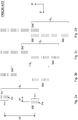
Figures 2a to 2d schematically show pairs of reference marks as included in consecutive swaths of printed information in a known method for measuring medium advance in a printer; -
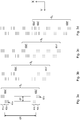
Figures 3a to 3d schematically show pairs of reference marks as included in consecutive swaths of printed information in a method for measuring medium advance in a printer according to the invention. - With reference to
Figures 1a and 1b , a scanning-type inkjet printer 100 comprises a plurality ofinkjet print heads print head carriage 150 arranged to move relative to arecording medium 200 along an axis of carriage motion Y while being guided by a guidingstructure 160. - The
printer 100 comprises adriving roller 170 for driving therecording medium 200 to move relative to the guidingstructure 160 along an axis of medium advance X normal to the axis of carriage motion Y. - Each
print head array jetting nozzles 180 for jetting out droplets of ink, eachnozzle array - The
carriage 150 carries ascanner 190 having a field ofview 191 extending along the axis of medium advance X. - In operation, a swath of information is printed onto the
recording medium 200 byjetting nozzles 180 of theprint heads recording medium 200 while thecarriage 150 is moving along the axis of carriage motion Y. - In between consecutive swaths, the
recording medium 200 is moved along the axis of medium advance X by thedriving roller 170, so that multiple swaths of information can be printed side by side on therecording medium 200. - Each time when the
recording medium 200 moves relative to the guidingstructure 160, the advance of therecording medium 200 is measured, and compared to an advance as expected based on a prescribed motion of thedriving roller 170. - For measuring the medium advance, two reference marks printed with different sub-arrays of
jetting nozzles 180 within the same onenozzle array scanner 190 to determine their relative position along the axis of medium advance X once the pair of reference marks, by transport of therecording medium 200, has reached an area which is covered by the field ofview 191 of thescanner 190 during a certain pass of thecarriage 150 relative to therecording medium 200. - With reference to
Figures 2a to 2d , in a method for measuring medium advance according to the prior art, in every swath of information Si printed, a reference mark assembly 50ai, 50bi is included, comprising one reference mark 50ai and another reference mark 50bi. - Each reference mark 50ai, 50bi comprises an
array recognizable dot sequences individual nozzle 180 of aspecific nozzle array dot sequence different dot sequences - The one reference mark 50ai and the other reference mark 50bi are each printed using a different one of two sub-arrays of
jetting nozzles 180 spaced apart within thenozzle array - By appropriate control of the
print head respective nozzle array - As a result of the distances dX, dY between the reference marks 50ai, 50bi within a certain reference mark assembly 50ai, 50bi, and as illustrated by the reference mark assemblies 50a1, 50b1; 50a2, 50b2; 50a3, 50b3; 50a4, 50b4 included in consecutive swaths of printed information S1 to S4 shown in
Figures 2a to 2d , after a certain number of swaths printed (four, in the shown example), the one reference mark 50a4 as included in a later swath S4 is printed in the vicinity of the other reference mark 50b1 as included in an earlier swath S1 (seeFigure 2d ). This allows the two reference marks 50a4, 50b1 to be scanned by thescanner 190 in the same one pass of thecarriage 150 relative to therecording medium 200, such that the relative position along the axis of medium advance X of the two reference marks 50a4, 50b1 can be checked, and the advance made by themedium 200 in between the printing of the earlier swath S1 and the printing of the later swath S4 can be determined. - With reference to
Figures 3a to 3d , in an embodiment of a method for measuring medium advance according to the invention, again, in every swath of information Si printed, a reference mark assembly 60ai, 60bi is included, comprising one reference mark 60ai and another reference mark 60bi. - Each reference mark 60ai, 60bi again comprises a
set recognizable dot sequences individual nozzle 180 of aspecific nozzle array dot sequence different dot sequences - Rather than a single array of dot sequences printed at a certain position along the axis of carriage motion Y, each reference mark 60ai, 60bi in this case comprises two
arrays dot sequences 63a; 63b, whicharrays print head respective nozzle array - The
respective arrays array 61a located at a specific end of the one reference mark 60ai, such as the front end or the back end of the one reference mark 60ai when seen along the axis of medium advance X, is off-set in a certain direction along the axis of carriage motion Y with respect to theother array 62a of the one reference mark 60ai. Anarray 61b located at a corresponding end of the other reference mark 60bi, meaning also the front end or the back end of the other reference mark 60bi when seen along the axis of medium advance X, respectively, is off-set in the opposite direction with respect to theother array 62b of the other reference mark 60bi. - Again, the one reference mark 60ai and the other reference mark 60bi are each printed using a different one of two sub-arrays of jetting
nozzles 180 spaced apart within thenozzle array - By appropriate control of the
print head respective nozzle array - As a result of the distance dX along the axis of medium advance X between the reference marks 60ai, 60bi included in a reference mark assembly 60ai, 60bi, and as illustrated by the reference mark assemblies 60a1, 60b1; 60a2, 60b2; 60a3, 60b3; 60a4, 60b4 included in consecutive swaths of printed information S1 to S4 shown in
Figures 3a to 3d , after a certain number of swaths printed (four, in the shown example), the one reference mark 60a4 as included in a later swath S4 is printed at around the same position along the axis of medium advance X as the other reference mark 60b1 as included in an earlier swath S1 (seeFigure 3d ). This allows the two reference marks 60a4, 60b1 to be scanned by thescanner 190 in the same one pass of thecarriage 150 relative to therecording medium 200, such that the relative position along the axis of medium advance X of the two reference marks 60a4, 60b1 can be checked, and the advance made by the medium 200 in between the printing of the earlier swath S1 and the printing of the later swath S4 can be determined. - As a result of the distance dY along the axis of carriage motion Y between the two
arrays dot sequences respective arrays structure 160 with relatively little chance of dot sequences of the two reference marks 60a4, 60b1 overlapping. - Having the one reference mark 60a4 as included in a later swath S4 and the other reference mark 60b1 as included in an earlier swath S1 extend along the same two parts of the guiding
structure 160 provides for the two reference marks 60a4, 60b1 to be influenced to the same extent by a certain imperfection present in the guidance provided by the guidingstructure 160. As a result, any influence of such an imperfection on the position of any of thearrays dot sequences printer 100. - A relative position of two reference marks 60a4, 60b1 along the axis of medium advance X can be determined by averaging the positions along the axis of medium advance X of all dots within a
dot sequence dot sequences - A method as described may also be used for determining a print-process related distance other than the advance of a
recording medium 200. Such a distance could include any distance along the axis of medium advance X measurable via the printing and scanning of a pair of reference marks, such as a difference in position along said axis X of a first and a second print head within a print head carriage, or a distance of travel of a guiding structure moving relative to a supporting table for supporting a stationary recording medium. - It is noted that for measuring a distance using the described method, different reference marks 60ai, 60bi need not necessarily be printed using different groups of
nozzles 180 within one and thesame array nozzles 180. The principle also works with groups ofnozzles 180 ofdifferent nozzle arrays different print heads - For sake of completeness, it is noted that a reference mark 60ai, 60bi or a
portion - Each one of
different arrays dot sequences 63a; 63b within a reference mark 60ai, 60bi, printed at a mutual distance dY along the axis of carriage motion Y, preferably comprises at least twodot sequences 63a; 63b to enable at least some of thedot sequences 63a; 63b of therespective arrays optical scanner 190 in case thearrays - Each of the
dot sequences dot sequence other dot sequences dot sequences dot sequences - Each one of two
arrays dot sequences 63a; 63b within each reference mark 60ai, 60bi may comprise half the set of alldot sequences -
Different arrays dot sequences 63a; 63b within a reference mark 60ai, 60bi, printed at a mutual distance dY along the axis of carriage motion Y, may also be printed at a mutual distance along the axis of medium of advance X which is larger than the distance in between individual dot sequences, to decrease the chance of overlap at a certain amount of medium advance betweenarrays more nozzles 180 in a certain sub-array ofnozzles 180 when printing a reference mark 60ai, 60bi with such a sub-array. - Whether the
different dot sequences 63a; 63b within a reference mark 60ai, 60bi are individually recognizable is noted to depend on the distance between theindividual dot sequences 63a; 63b. Preferably, neighboringdot sequences 63a; 63b within a reference mark 60ai, 60bi are arranged at such a distance, that noother dot sequence 63a; 63b would fit in between. This allows a relatively large number ofdot sequences 63a; 63b to fit in the field ofview 191 of anoptical scanner 190, which provides for a relatively accurate measurement of a position of a reference mark 60ai, 60bi along the axis of medium advance X. - Preferably, the number of
dot sequences 63a; 63b within a reference mark 60ai, 60bi equals at least the number ofdot sequences 53a; 53b of previously known reference marks 50ai, 50bi (eight, for the embodiment shown inFigures 2a-2d ), so that at least a same degree of accuracy can be obtained as with known methods for a given size of a field ofview 191 of anoptical scanner 190. - It is to be understood that the disclosed embodiments are merely exemplary of the invention, which can be embodied in various forms. Specific structural and functional details are not to be interpreted as limiting, but merely as a basis for the claims and as a teaching for one skilled in the art to variously employ the present invention in virtually any appropriately detailed structure. In particular, features presented and described in separate dependent claims may be applied in combination, and any advantageous combination of such claims is herewith disclosed.
- The invention being thus described, it will be obvious that the same may be varied in many ways. Such variations are not to be regarded as a departure from the spirit and scope of the invention, and all such modifications as would be obvious to one skilled in the art are intended to be included within the scope of the following claims.
Claims (5)
- Method for determining a distance in a printer (100) comprising one or more print heads (110, 120, 130, 140) mounted on a carriage (150) arranged to move relative to a recording medium (200) along an axis of carriage motion (Y), the one or more print heads (110, 120, 130, 140) having at least one array (111, 121, 131, 141) of printing elements (180), wherein a swath of information (S1, S2, S3, S4) can be printed onto a recording medium (200) by an array (111, 121, 131, 141) of printing elements (180) of a print head (110, 120, 130, 140) printing information onto the recording medium (200) while the carriage (150) is moving, the method comprising the steps of:- including in a first swath of printed information (S1) a first reference mark (60b1) printed with one array (111, 121, 131, 141) of printing elements (180);- including in a second swath of printed information (S4) a second reference mark (60a4) printed with the one array (111, 121, 131, 141) of printing elements (180), and- determining a relative position of the two reference marks (60b1, 60a4), characterized by the step of printing specific portions (61a, 62a; 61b, 62b) of each reference mark (60b1, 60a4) at a mutual distance (dY) along the axis of carriage motion (Y), wherein the specific portions (61a, 61b; 62a, 62b) are off-set in opposite directions along the axis of carriage motion (Y) for the first reference mark (60b1) and the second reference mark (60a4).
- Method according to claim 1, wherein each reference mark (60b1, 60a4) comprises a set (61a, 62a; 61b, 62b) of individually recognizable dot sequences (63a, 63b) spaced apart along a certain axis (X), wherein each specific portion (61a, 62a; 61b, 62b) of a reference mark (60b1, 60a4) comprises an array (61a, 62a, 61b, 62b) of at least two dot sequences (63a; 63b) consecutively arranged along said axis (X).
- Method according to claim 1 or 2, wherein each reference mark (60b1, 60a4) comprises a set (61a, 62a; 61b, 62b) of individually recognizable dot sequences (63a, 63b) spaced apart along a certain axis (X), wherein each specific portion (61a, 62a; 61b, 62b) of a reference mark (60b1, 60a4) comprises half the set of all dot sequences (63a, 63b) within the reference mark (60b1, 60a4).
- Method according to one of the preceding claims, wherein each reference mark (60b1, 60a4) comprises a set (61a, 62a; 61b, 62b) of individually recognizable dot sequences (63a, 63b) spaced apart along a certain axis (X), wherein the specific portions (61a, 62a; 61b, 62b) of each reference mark (60b1, 60a4) are printed at a mutual distance along said axis (X) larger than the distance in between individual dot sequences (63a, 63b) along said axis (X).
- Method for measuring medium advance in a printer (100), wherein the medium advance is determined using a method according to one of the preceding claims.
Priority Applications (1)
| Application Number | Priority Date | Filing Date | Title |
|---|---|---|---|
| EP18180765.2A EP3587130A1 (en) | 2018-06-29 | 2018-06-29 | Method for determining a distance in a printer |
Applications Claiming Priority (1)
| Application Number | Priority Date | Filing Date | Title |
|---|---|---|---|
| EP18180765.2A EP3587130A1 (en) | 2018-06-29 | 2018-06-29 | Method for determining a distance in a printer |
Publications (1)
| Publication Number | Publication Date |
|---|---|
| EP3587130A1 true EP3587130A1 (en) | 2020-01-01 |
Family
ID=62837718
Family Applications (1)
| Application Number | Title | Priority Date | Filing Date |
|---|---|---|---|
| EP18180765.2A Withdrawn EP3587130A1 (en) | 2018-06-29 | 2018-06-29 | Method for determining a distance in a printer |
Country Status (1)
| Country | Link |
|---|---|
| EP (1) | EP3587130A1 (en) |
Citations (5)
| Publication number | Priority date | Publication date | Assignee | Title |
|---|---|---|---|---|
| US20020130915A1 (en) * | 2001-03-16 | 2002-09-19 | Olympus Optical Co., Ltd. | Image recording apparatus |
| EP2960062A1 (en) * | 2014-06-26 | 2015-12-30 | OCE-Technologies B.V. | Method for calibrating accurate paper steps |
| US20160089883A1 (en) * | 2014-09-26 | 2016-03-31 | Seiko Epson Corporation | Liquid discharging apparatus and transport amount adjustment method |
| US20170072715A1 (en) * | 2015-09-11 | 2017-03-16 | Seiko Epson Corporation | Liquid ejecting apparatus and transport amount adjusting method |
| EP3323619A1 (en) * | 2016-11-22 | 2018-05-23 | Ricoh Company Ltd. | Image forming apparatus, method for calculating actual distance of deviation, and computer program product storing same |
-
2018
- 2018-06-29 EP EP18180765.2A patent/EP3587130A1/en not_active Withdrawn
Patent Citations (5)
| Publication number | Priority date | Publication date | Assignee | Title |
|---|---|---|---|---|
| US20020130915A1 (en) * | 2001-03-16 | 2002-09-19 | Olympus Optical Co., Ltd. | Image recording apparatus |
| EP2960062A1 (en) * | 2014-06-26 | 2015-12-30 | OCE-Technologies B.V. | Method for calibrating accurate paper steps |
| US20160089883A1 (en) * | 2014-09-26 | 2016-03-31 | Seiko Epson Corporation | Liquid discharging apparatus and transport amount adjustment method |
| US20170072715A1 (en) * | 2015-09-11 | 2017-03-16 | Seiko Epson Corporation | Liquid ejecting apparatus and transport amount adjusting method |
| EP3323619A1 (en) * | 2016-11-22 | 2018-05-23 | Ricoh Company Ltd. | Image forming apparatus, method for calculating actual distance of deviation, and computer program product storing same |
Similar Documents
| Publication | Publication Date | Title |
|---|---|---|
| JP5620878B2 (en) | Method and system for aligning a print head to compensate for dimensional changes in a medium in an ink jet printer | |
| US6076915A (en) | Inkjet printhead calibration | |
| US6364447B1 (en) | Correction system for droplet placement errors in the scan axis in inkjet printers | |
| JP4434325B2 (en) | Printing method to compensate for minute strip pattern | |
| JP3417657B2 (en) | Apparatus and method for offset correction of multicolor ink jet print cartridge | |
| JP5063327B2 (en) | Inkjet recording apparatus and adjustment value acquisition method | |
| US6623096B1 (en) | Techniques for measuring the position of marks on media and for aligning inkjet devices | |
| EP2093066B1 (en) | A method for identifying misdirecting nozzles in an inkjet printing apparatus | |
| US9358790B2 (en) | Printing apparatus and landing position determination method | |
| EP1029692B1 (en) | Printing apparatus | |
| JPH071726A (en) | Device for alignment of ink jet cartridge | |
| JPH071725A (en) | Device for alignment of ink jet cartridge | |
| EP2062734B1 (en) | Method for calibrating an inkjet printhead and inkjet printing apparatus | |
| CN101905576A (en) | Recording equipment and method for adjusting recording position | |
| US6568784B2 (en) | Image recording apparatus | |
| US7407251B2 (en) | Printing method, computer-readable medium, printing apparatus, printing system, and pattern for correction | |
| CN102991157A (en) | Method and system of in-document detection of weak or missing inkjets in an inkjet printer | |
| US8974034B2 (en) | Ink-jet recording apparatus and method of detecting inclination of nozzle row of ink-jet head | |
| US7891757B2 (en) | Marking element registration | |
| CN105799343A (en) | Ink-jet printing apparatus and printing medium stepping error detection method | |
| JP2008536706A (en) | Color registration test pattern | |
| US8708444B2 (en) | Inkjet printer and ejection timing correction method | |
| JP6319948B2 (en) | Recording device | |
| JPH06340065A (en) | Ink jet cartridge arranging method | |
| EP1413444B1 (en) | Media skew compensation in printer device |
Legal Events
| Date | Code | Title | Description |
|---|---|---|---|
| PUAI | Public reference made under article 153(3) epc to a published international application that has entered the european phase |
Free format text: ORIGINAL CODE: 0009012 |
|
| STAA | Information on the status of an ep patent application or granted ep patent |
Free format text: STATUS: THE APPLICATION HAS BEEN PUBLISHED |
|
| AK | Designated contracting states |
Kind code of ref document: A1 Designated state(s): AL AT BE BG CH CY CZ DE DK EE ES FI FR GB GR HR HU IE IS IT LI LT LU LV MC MK MT NL NO PL PT RO RS SE SI SK SM TR |
|
| AX | Request for extension of the european patent |
Extension state: BA ME |
|
| STAA | Information on the status of an ep patent application or granted ep patent |
Free format text: STATUS: THE APPLICATION HAS BEEN WITHDRAWN |
|
| 18W | Application withdrawn |
Effective date: 20200217 |
|
| RAP1 | Party data changed (applicant data changed or rights of an application transferred) |
Owner name: CANON PRODUCTION PRINTING HOLDING B.V. |