EP3587127A1 - Electronic hand stamp - Google Patents
Electronic hand stamp Download PDFInfo
- Publication number
- EP3587127A1 EP3587127A1 EP18179493.4A EP18179493A EP3587127A1 EP 3587127 A1 EP3587127 A1 EP 3587127A1 EP 18179493 A EP18179493 A EP 18179493A EP 3587127 A1 EP3587127 A1 EP 3587127A1
- Authority
- EP
- European Patent Office
- Prior art keywords
- electronic hand
- hand stamp
- leds
- indicator leds
- control circuit
- Prior art date
- Legal status (The legal status is an assumption and is not a legal conclusion. Google has not performed a legal analysis and makes no representation as to the accuracy of the status listed.)
- Withdrawn
Links
Images


Classifications
-
- B—PERFORMING OPERATIONS; TRANSPORTING
- B41—PRINTING; LINING MACHINES; TYPEWRITERS; STAMPS
- B41K—STAMPS; STAMPING OR NUMBERING APPARATUS OR DEVICES
- B41K1/00—Portable hand-operated devices without means for supporting or locating the articles to be stamped, i.e. hand stamps; Inking devices or other accessories therefor
- B41K1/36—Details
-
- B—PERFORMING OPERATIONS; TRANSPORTING
- B41—PRINTING; LINING MACHINES; TYPEWRITERS; STAMPS
- B41J—TYPEWRITERS; SELECTIVE PRINTING MECHANISMS, i.e. MECHANISMS PRINTING OTHERWISE THAN FROM A FORME; CORRECTION OF TYPOGRAPHICAL ERRORS
- B41J3/00—Typewriters or selective printing or marking mechanisms characterised by the purpose for which they are constructed
- B41J3/36—Typewriters or selective printing or marking mechanisms characterised by the purpose for which they are constructed for portability, i.e. hand-held printers or laptop printers
-
- B—PERFORMING OPERATIONS; TRANSPORTING
- B41—PRINTING; LINING MACHINES; TYPEWRITERS; STAMPS
- B41J—TYPEWRITERS; SELECTIVE PRINTING MECHANISMS, i.e. MECHANISMS PRINTING OTHERWISE THAN FROM A FORME; CORRECTION OF TYPOGRAPHICAL ERRORS
- B41J29/00—Details of, or accessories for, typewriters or selective printing mechanisms not otherwise provided for
- B41J29/38—Drives, motors, controls or automatic cut-off devices for the entire printing mechanism
- B41J29/393—Devices for controlling or analysing the entire machine ; Controlling or analysing mechanical parameters involving printing of test patterns
-
- B—PERFORMING OPERATIONS; TRANSPORTING
- B41—PRINTING; LINING MACHINES; TYPEWRITERS; STAMPS
- B41K—STAMPS; STAMPING OR NUMBERING APPARATUS OR DEVICES
- B41K1/00—Portable hand-operated devices without means for supporting or locating the articles to be stamped, i.e. hand stamps; Inking devices or other accessories therefor
- B41K1/006—Pocket stamps
Definitions
- An electronic hand stamp generally is a portable electronic device for producing stamp marks by printing on a substrate (e.g. a document or other object to be stamped).
- An electronic hand stamp of the present type comprises an inkjet printhead with nozzles directed toward a bottom side of the electronic hand stamp, a control circuit and a motion detector, wherein the control circuit is connected to the motion detector and to the inkjet printhead and configured to control the inkjet printhead in response to readings received from the motion detector, thereby producing a printed image when the electronic hand stamp is manually moved over the substrate.
- the present electronic hand stamp can be used as an electronic replacement for traditional (mechanical) hand stamps with rubber stamp plates and ink pads. It transfers a pre-defined image (the motif) to a substrate, which typically already holds information. The information in the motif augments the information already present on the substrate.
- US 4,947,262 A shows a hand-held manually sweeping printing apparatus.
- the apparatus has a thermal printer head and a roll of a thermal-transfer ink ribbon.
- the apparatus comprises three LEDs (light-emitting diodes): a power-supply pilot lamp, a memory pilot lamp and an alarm lamp.
- Each LED indicates only one binary status. Therefore, each status indicated by one of the LEDs is visible only from one side of the apparatus.
- error states or warnings concerning the printer operation might not be recognizable by the user during the printer operation, depending on how the apparatus is positioned and held.
- portable electronic devices with the ability to print are known, albeit for a different purpose.
- portable printer-scanner devices which serve as a means for replicating existing documents. Such devices typically operate on a first substrate holding information by scanning said information without modifying the first substrate; subsequently they operate on a second substrate that is empty (does not hold information) and print a copy of the scanned information on the second substrate.
- the invention proposes an electronic hand stamp of the kind stated in the outset, wherein the electronic hand stamp comprises at least four indicator LEDs connected to the control circuit, wherein at least one of the at least four indicator LEDs is arranged on every side perpendicular to the bottom side of the electronic hand stamp.
- the indicator LEDs are visible from every side or angle. Thus, the information indicated by the indicator LEDs is visible irrespective of the current position of the electronic hand stamp or the grasp thereon.
- the invention proposes a method for controlling an electronic hand stamp as defined above, wherein the at least four indicator LEDs are controlled in an interdependent fashion.
- the indicator LEDs are not configured to indicate operationally independent signals, but to cooperate in order to together indicate the same one or more signals concerning the operating status of the electronic hand stamp.
- the electronic hand stamp comprises at least six indicator LEDs, preferably at least eight indicator LEDs, connected to the control circuit.
- a larger number of indicator LEDs increases the visibility of the indicator LEDs and thus - because they all basically indicate the same information - of the indicated operating status.
- the indicator LEDs are multicolour LEDs (e.g. RGB LEDs), wherein the control circuit is configured to control the indicator LEDs to glow in the same colour, in particular either simultaneously or time-delayed (in an animation).
- multicolour LEDs the number and arrangement of LEDs can be improved compared to a corresponding larger number of single-color LEDs.
- a smaller number of LEDs can indicate a comparably larger number of operating statuses by colour-encoding.
- the electronic hand stamp may further comprise a diffuser, wherein at least two indicator LEDs are optically connected with the diffuser.
- the diffuser blurs the gap or limit between two adjacent LEDs; the diffuser typically includes a light guide and a scattering surface.
- the scattering surface might be formed by a diffusion filter (e.g. milk glass or similar plastics material).
- the distance between the indicator LEDs is small enough that the brightness of the LED-light through the diffuser is essentially homogeneous.
- Essentially homogeneous means that the brightness of the emitted light does not drop below 70 % of the maximum brightness under full-power conditions, optionally the brightness of the emitted light does not drop below 90 % of the maximum brightness under full-power conditions.
- a continuous light strip can be formed.
- the light strip may be arranged to surround the outer side walls of the electronic hand stamp.
- the at least four indicator LEDs are arranged on two or more printed circuit boards (PCBs).
- PCBs printed circuit boards
- Two or more printed circuit boards may preferably be arranged perpendicular to the bottom side of the electronic stamp (i.e. in a vertical arrangement, short "vertical PCB").
- Using printed circuit boards as supports for the LEDs has several advantages: they provide a cost effective surface mount process and an easy connection to a control circuit. Rigid PCBs as well as flexible PCBs can be used.
- At least one of the PCBs can be a horizontal PCB, wherein the one or more indicator LEDs arranged thereon are right angle LEDs. Moreover, at least one indicator LED can be arranged on a flexible PCB, wherein the flexible PCB is preferably extending from and connected to a vertical PCB.
- the electronic hand stamp comprises at least one target LED (or substrate-lightning LED) for illuminating a print area adjacent the printhead, said at least one target LED being connected to the control circuit.
- at least two target LEDs are foreseen, e.g. one on each of opposite sides of the printhead. Illumination of the print area helps in aligning the electronic hand stamp with respect to the substrate, in particular with respect to an existing layout of the substrate (e.g. form fields indicated on a pre-printed paper form).
- the at least two target LEDs are preferably connected to the control circuit, wherein the control circuit is configured to switch on at least one target LED on one of the sides of the printhead, preferably the side corresponding to the direction in which the printhead is being moved.
- This control of the target LEDs helps to avoid ambiguities concerning the alignment of one of the two sides of the printhead with respect to the substrate. Also, it provides feedback to the user concerning the motion detection performed by the electronic hand stamp by indicating the direction in which the stamp assumes it is moved.
- the at least one target LED is optically connected to a prism for deflecting light emitted by the at least one target LED to the print area.
- a prism allows for the target LED to be supported on the same PCB as one or more of the indicator LEDs, which are configured to emit light not at the print area (facing the bottom side) but to the vertical sides of the electronic hand stamp.
- the method comprises controlling the at least four indicator LEDs to simultaneously glow in a predefined colour to indicate an operating status of the stamp.
- the operating status is a member selected from a group consisting of: power-on, battery weak/empty, ink empty, other error, connection established, and transfer finished.
- the control of the electronic hand stamp can be configured to use different predefined colours, each associated with one of the operating statuses.
- the indicator LEDs are controlled to all glow in the predefined colour associated with said operating status (e.g. all glowing green upon power-on).
- the method may particularly comprise controlling the at least four indicator LEDs to glow in a time-delayed fashion and in order of their circumferential arrangement, preferably for at least one turn, to indicate an ongoing operation.
- the LEDs are controlled to flash at a common frequency and with a phase shift that is larger between more distant LEDs than between adjacent LEDs.
- the ongoing operation can be a member selected from a group consisting of: transfer in progress, and printing in progress.
- the indicator LEDs may be controlled to signal a rotating blue light that stops once the transfer is finished.
- the present method may preferably comprise switching on at least one target LED on one of the sides of the printhead, preferably the side corresponding to the direction in which the printhead is being moved when a direction of movement of the electronic hand stamp is detected, and switching off the other target LEDs.
- Fig. 1 shows an electronic hand stamp 1 having a generally opaque cover 2 with a windowed portion 3 and a bottom side 4.
- the windowed portion 3 is made of a transparent material.
- the electronic hand stamp 1 In the operating position shown in fig. 1 , the electronic hand stamp 1 is positioned with its bottom side 4 flat on a plane substrate 5.
- an inkjet printhead (not shown) has its nozzles directed toward the bottom side 4 and the substrate 5 in order to print thereon.
- the inkjet printhead is controlled by a control circuit 30 (see fig. 2 ) integrated in the electronic hand stamp 1.
- the control circuit 30 is connected to a motion detector, for example an optical sensor directed at the substrate 5, a gyroscope and/or an accelerometer, and configured to received readings from the motion detector and control the inkjet printhead in response to those readings. Specifically, the control is configured to produce an undistorted print image irrespective of a speed of movement of the electronic hand stamp 1 relative to the substrate 5 or variations in said speed.
- the windowed portion 3 allows a user to supervise the printing process immediately next to the printhead. Extending from the windowed portion 3 of the cover 2, the electronic hand stamp 1 comprises indicator projections 6 on each side (compare fig. 3 ).
- the indicator projections 6 have a central notch 7 marking the centre of the arrangement of nozzles of the inkjet printhead, i.e. on a line connecting the notches 7 of the two indicator projections 6.
- the electronic hand stamp 1 Embedded in the cover 2, the electronic hand stamp 1 comprises a light strip 8 (also "light pipe”).
- the part of the light strip 8 visible on the outside of the assembled electronic hand stamp 1 is a diffuser 9 that circumferentially surrounds the electronic hand stamp 1.
- the diffuser 9 comprises a diffusion filter 9' having a light scattering surface.
- Figures 2 and 3 show the other components of the light strip 8.
- the electronic hand stamp 1 comprises eight indicator LEDs 10, 11, 12, 13, 14, 15, 16, 17.
- Two indicator LEDs 10, 11; 12, 13; 14, 15; 16, 17 are arranged on every side of the electronic hand stamp 1 perpendicular to the bottom side 4.
- All eight indicator LEDs 10-17 are optically connected with a light guide 18 of the diffuser 9.
- the light guide 18 comprises four segments 19-22, each connected to one or more of the indicator LEDs 10-17. More specifically, the segments 19-22 of the light guide 18 together define a continuous outer surface 23, on which the diffusion filter 9' of the diffuser 9 is attached.
- the diffusion filter 9' may be for example a scattering foil adhered to the continuous outer surface 23.
- the segments 19-22 comprise a main portion that is parallel to the continuous outer surface 23 and from which legs 24 extend to each of the connected indicator LEDs 10-17.
- Each leg 24 at its end facing the respective indicator LED 10-17 has a flat end surface 25 that is perpendicular to the principal direction of light emitted from the respective indicator LED 10-17. This arrangement provides for an efficient coupling of light into the light guide 18.
- the distance between the indicator LEDs 10-17 is small enough that the brightness of the LED-light through the diffuser 9 is essentially homogeneous.
- the homogeneous distribution of light is achieved by total internal reflection in the light guide 18 and partial back scattering from the diffusion filter 9' into the light guide 18.
- the scattering of the light can optionally be improved by using a material which contains scattering particles for the light guide 18.
- a homogeneous distribution can also be achieved without scattering, a scattering surface or scattering particles.
- the indicator LEDs 10-17 are arranged on two vertical printed circuit boards (PCBs) 26, 27, one horizontal PCB 28 and one flexible PCB 29 extending from one of the vertical PCBs 27. All indicator LEDs 10-17 are connected to a common control circuit 30 arranged on one or more of the PCBs 26. Accordingly, all PCBs 26-29 are electronically connected, e.g. with a common bus system.
- the indicator LEDs 12, 13 arranged on the horizontal PCB 28 are right angle LEDs, i.e. having a principal light emission direction parallel to the principal plane of the horizontal PCB 28. All eight indicator LEDs 10-17 are multicolour LEDs.
- the control circuit 30 is configured to control the indicator LEDs 10-17 in an interdependent fashion, for example to glow in the same colour, in particular either simultaneously or time-delayed.
- the electronic hand stamp 1 comprises two target LEDs 31, 32, one on each of the vertical PCBs 26, 27.
- the target LEDs 31, 32 are bright white-light LEDs that are each optically connected to a respective prism 33, 34 for deflecting light emitted by the associated target LED 31, 32 to the print area on the substrate 5 adjacent the printhead, thereby illuminating the print area.
- the target LEDs 31, 32 are connected to the control circuit 30 of the electronic hand stamp 1.
- the control circuit 30 is configured to switch on the target LED 31; 32 on the side of the printhead corresponding to the direction in which the printhead is being moved (according to the reading of the motion sensor).
- Fig. 4 shows a view from below onto the bottom side 4 of the electronic hand stamp 1.
- the printhead 36 is positioned essentially centred between the prisms 33, 34 of the target LEDs 31, 32.
- Motion of the electronic hand stamp 1 is detected with an optical motion detector 35, which is in principle similar to detectors used for optical computer mice.
- the electronic hand stamp 1 is moved in one or the other direction along an essentially linear axis of motion 37.
- a row of inkjet nozzles of the printhead 36 is arranged perpendicular to the axis of motion 37.
- the rollers 38 guide and help to maintain a straight path of movement during printing, i.e. along the axis of motion 37.
Abstract
Electronic hand stamp (1) comprising:an inkjet printhead with nozzles directed toward a bottom side (4) of the electronic hand stamp (1),a control circuit (30) anda motion detector,wherein the control circuit (30) is connected to the motion detector and to the inkjet printhead and configured to control the inkjet printhead in response to readings received from the motion detector,wherein the electronic hand stamp (1) comprises at least four indicator LEDs (10-17) connected to the control circuit (30), wherein at least one of the at least four indicator LEDs (10-17) is arranged on every side perpendicular to the bottom side (4) of the electronic hand stamp (1).
Description
- The invention concerns an electronic hand stamp and a method for controlling the same. An electronic hand stamp generally is a portable electronic device for producing stamp marks by printing on a substrate (e.g. a document or other object to be stamped). An electronic hand stamp of the present type comprises an inkjet printhead with nozzles directed toward a bottom side of the electronic hand stamp, a control circuit and a motion detector, wherein the control circuit is connected to the motion detector and to the inkjet printhead and configured to control the inkjet printhead in response to readings received from the motion detector, thereby producing a printed image when the electronic hand stamp is manually moved over the substrate.
- The present electronic hand stamp can be used as an electronic replacement for traditional (mechanical) hand stamps with rubber stamp plates and ink pads. It transfers a pre-defined image (the motif) to a substrate, which typically already holds information. The information in the motif augments the information already present on the substrate.
- For a similar purpose,
US 4,947,262 A shows a hand-held manually sweeping printing apparatus. The apparatus has a thermal printer head and a roll of a thermal-transfer ink ribbon. The apparatus comprises three LEDs (light-emitting diodes): a power-supply pilot lamp, a memory pilot lamp and an alarm lamp. Each LED indicates only one binary status. Therefore, each status indicated by one of the LEDs is visible only from one side of the apparatus. In particular, error states or warnings concerning the printer operation might not be recognizable by the user during the printer operation, depending on how the apparatus is positioned and held. - Other portable electronic devices with the ability to print are known, albeit for a different purpose. Specifically, portable printer-scanner devices are known, which serve as a means for replicating existing documents. Such devices typically operate on a first substrate holding information by scanning said information without modifying the first substrate; subsequently they operate on a second substrate that is empty (does not hold information) and print a copy of the scanned information on the second substrate.
- Examples of such devices are shown in
US 7,426,050 B2 , inDE 103 53 875 A1 and inDE 10 2005 014 227 B4 . - It is an object of the present invention, to provide for a reliable user feedback means that can be noticed during operation, thereby facilitating error-free use of the electronic hand stamp.
- The invention proposes an electronic hand stamp of the kind stated in the outset, wherein the electronic hand stamp comprises at least four indicator LEDs connected to the control circuit, wherein at least one of the at least four indicator LEDs is arranged on every side perpendicular to the bottom side of the electronic hand stamp. The indicator LEDs are visible from every side or angle. Thus, the information indicated by the indicator LEDs is visible irrespective of the current position of the electronic hand stamp or the grasp thereon.
- Correspondingly, the invention proposes a method for controlling an electronic hand stamp as defined above, wherein the at least four indicator LEDs are controlled in an interdependent fashion. In other words, the indicator LEDs are not configured to indicate operationally independent signals, but to cooperate in order to together indicate the same one or more signals concerning the operating status of the electronic hand stamp.
- In a preferred embodiment, the electronic hand stamp comprises at least six indicator LEDs, preferably at least eight indicator LEDs, connected to the control circuit. A larger number of indicator LEDs increases the visibility of the indicator LEDs and thus - because they all basically indicate the same information - of the indicated operating status.
- Advantageously, the indicator LEDs are multicolour LEDs (e.g. RGB LEDs), wherein the control circuit is configured to control the indicator LEDs to glow in the same colour, in particular either simultaneously or time-delayed (in an animation). By using multicolour LEDs, the number and arrangement of LEDs can be improved compared to a corresponding larger number of single-color LEDs. In particular, a smaller number of LEDs can indicate a comparably larger number of operating statuses by colour-encoding.
- The electronic hand stamp may further comprise a diffuser, wherein at least two indicator LEDs are optically connected with the diffuser. The diffuser blurs the gap or limit between two adjacent LEDs; the diffuser typically includes a light guide and a scattering surface. The scattering surface might be formed by a diffusion filter (e.g. milk glass or similar plastics material).
- In this context, it is advantageous, if the distance between the indicator LEDs is small enough that the brightness of the LED-light through the diffuser is essentially homogeneous. Essentially homogeneous here means that the brightness of the emitted light does not drop below 70 % of the maximum brightness under full-power conditions, optionally the brightness of the emitted light does not drop below 90 % of the maximum brightness under full-power conditions.
- When all of the at least four indicator LEDs are optically connected with the diffuser, and in particular the diffuser circumferentially surrounds the electronic hand stamp, a continuous light strip can be formed. The light strip may be arranged to surround the outer side walls of the electronic hand stamp.
- It has turned out beneficial, if the at least four indicator LEDs are arranged on two or more printed circuit boards (PCBs). Two or more printed circuit boards may preferably be arranged perpendicular to the bottom side of the electronic stamp (i.e. in a vertical arrangement, short "vertical PCB"). Using printed circuit boards as supports for the LEDs has several advantages: they provide a cost effective surface mount process and an easy connection to a control circuit. Rigid PCBs as well as flexible PCBs can be used.
- At least one of the PCBs can be a horizontal PCB, wherein the one or more indicator LEDs arranged thereon are right angle LEDs. Moreover, at least one indicator LED can be arranged on a flexible PCB, wherein the flexible PCB is preferably extending from and connected to a vertical PCB.
- In a particularly preferred embodiment, the electronic hand stamp comprises at least one target LED (or substrate-lightning LED) for illuminating a print area adjacent the printhead, said at least one target LED being connected to the control circuit. Preferably at least two target LEDs are foreseen, e.g. one on each of opposite sides of the printhead. Illumination of the print area helps in aligning the electronic hand stamp with respect to the substrate, in particular with respect to an existing layout of the substrate (e.g. form fields indicated on a pre-printed paper form).
- In this context, the at least two target LEDs are preferably connected to the control circuit, wherein the control circuit is configured to switch on at least one target LED on one of the sides of the printhead, preferably the side corresponding to the direction in which the printhead is being moved. This control of the target LEDs helps to avoid ambiguities concerning the alignment of one of the two sides of the printhead with respect to the substrate. Also, it provides feedback to the user concerning the motion detection performed by the electronic hand stamp by indicating the direction in which the stamp assumes it is moved.
- Advantageously, the at least one target LED is optically connected to a prism for deflecting light emitted by the at least one target LED to the print area. The use of a prism allows for the target LED to be supported on the same PCB as one or more of the indicator LEDs, which are configured to emit light not at the print area (facing the bottom side) but to the vertical sides of the electronic hand stamp.
- With regard to the inventive method, it is preferred, that the method comprises controlling the at least four indicator LEDs to simultaneously glow in a predefined colour to indicate an operating status of the stamp. For example, the operating status is a member selected from a group consisting of: power-on, battery weak/empty, ink empty, other error, connection established, and transfer finished. The control of the electronic hand stamp can be configured to use different predefined colours, each associated with one of the operating statuses. When the electronic hand stamp reaches an operating status associated with an indication by the indicator LEDs, the indicator LEDs are controlled to all glow in the predefined colour associated with said operating status (e.g. all glowing green upon power-on).
- With further regard to the inventive method, the method may particularly comprise controlling the at least four indicator LEDs to glow in a time-delayed fashion and in order of their circumferential arrangement, preferably for at least one turn, to indicate an ongoing operation. For example, the LEDs are controlled to flash at a common frequency and with a phase shift that is larger between more distant LEDs than between adjacent LEDs. To provide an indication that is readily understandable from any side of the electronic hand stamp, it is advantageous, if the flashing of the LEDs and the time delay are configured such that the appearance of a rotating light is created. The ongoing operation can be a member selected from a group consisting of: transfer in progress, and printing in progress. For example, during a transfer of image data from a host device to the electronic hand stamp, the indicator LEDs may be controlled to signal a rotating blue light that stops once the transfer is finished.
- With respect to the use of target LEDs, the present method may preferably comprise switching on at least one target LED on one of the sides of the printhead, preferably the side corresponding to the direction in which the printhead is being moved when a direction of movement of the electronic hand stamp is detected, and switching off the other target LEDs.
- Referring now to the drawings, wherein the figures are for purposes of illustrating the present invention and not for purposes of limiting the same,
-
fig. 1 schematically shows a figurative view of an electronic hand stamp according to the present invention, -
fig. 2 schematically shows a partial figurative view of the electronic hand stamp according tofig. 1 in an opened configuration, -
fig. 3 schematically shows a horizontal cut of the electronic hand stamp according tofigures 1 and2 , and -
fig. 4 shows a bottom view of the electronic hand stamp according to the previous figures. -
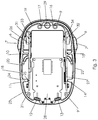
Fig. 1 shows an electronic hand stamp 1 having a generallyopaque cover 2 with a windowedportion 3 and a bottom side 4. The windowedportion 3 is made of a transparent material. In the operating position shown infig. 1 , the electronic hand stamp 1 is positioned with its bottom side 4 flat on aplane substrate 5. In this position, an inkjet printhead (not shown) has its nozzles directed toward the bottom side 4 and thesubstrate 5 in order to print thereon. The inkjet printhead is controlled by a control circuit 30 (seefig. 2 ) integrated in the electronic hand stamp 1. Thecontrol circuit 30 is connected to a motion detector, for example an optical sensor directed at thesubstrate 5, a gyroscope and/or an accelerometer, and configured to received readings from the motion detector and control the inkjet printhead in response to those readings. Specifically, the control is configured to produce an undistorted print image irrespective of a speed of movement of the electronic hand stamp 1 relative to thesubstrate 5 or variations in said speed. Thewindowed portion 3 allows a user to supervise the printing process immediately next to the printhead. Extending from thewindowed portion 3 of thecover 2, the electronic hand stamp 1 comprises indicator projections 6 on each side (comparefig. 3 ). The indicator projections 6 have a central notch 7 marking the centre of the arrangement of nozzles of the inkjet printhead, i.e. on a line connecting the notches 7 of the two indicator projections 6. - Embedded in the
cover 2, the electronic hand stamp 1 comprises a light strip 8 (also "light pipe"). The part of thelight strip 8 visible on the outside of the assembled electronic hand stamp 1 is adiffuser 9 that circumferentially surrounds the electronic hand stamp 1. Thediffuser 9 comprises a diffusion filter 9' having a light scattering surface. -
Figures 2 and3 show the other components of thelight strip 8. As can be seen, the electronic hand stamp 1 comprises eightindicator LEDs indicator LEDs 10, 11; 12, 13; 14, 15; 16, 17 are arranged on every side of the electronic hand stamp 1 perpendicular to the bottom side 4. All eight indicator LEDs 10-17 are optically connected with alight guide 18 of thediffuser 9. Thelight guide 18 comprises four segments 19-22, each connected to one or more of the indicator LEDs 10-17. More specifically, the segments 19-22 of thelight guide 18 together define a continuousouter surface 23, on which the diffusion filter 9' of thediffuser 9 is attached. The diffusion filter 9' may be for example a scattering foil adhered to the continuousouter surface 23. The segments 19-22 comprise a main portion that is parallel to the continuousouter surface 23 and from whichlegs 24 extend to each of the connected indicator LEDs 10-17. Eachleg 24 at its end facing the respective indicator LED 10-17 has aflat end surface 25 that is perpendicular to the principal direction of light emitted from the respective indicator LED 10-17. This arrangement provides for an efficient coupling of light into thelight guide 18. - The distance between the indicator LEDs 10-17 is small enough that the brightness of the LED-light through the
diffuser 9 is essentially homogeneous. The homogeneous distribution of light is achieved by total internal reflection in thelight guide 18 and partial back scattering from the diffusion filter 9' into thelight guide 18. The scattering of the light can optionally be improved by using a material which contains scattering particles for thelight guide 18. However, a homogeneous distribution can also be achieved without scattering, a scattering surface or scattering particles. Hence, it is those two elements and their respective optical properties that define the number of indicator LEDs required to homogeneously illuminate or "supply" a given length of thelight strip 8. Another influence is the optical coupling between adjacent segments 19-22 of thelight guide 18 parallel to the continuousouter surface 23. - The indicator LEDs 10-17 are arranged on two vertical printed circuit boards (PCBs) 26, 27, one
horizontal PCB 28 and oneflexible PCB 29 extending from one of thevertical PCBs 27. All indicator LEDs 10-17 are connected to acommon control circuit 30 arranged on one or more of thePCBs 26. Accordingly, all PCBs 26-29 are electronically connected, e.g. with a common bus system. Theindicator LEDs horizontal PCB 28 are right angle LEDs, i.e. having a principal light emission direction parallel to the principal plane of thehorizontal PCB 28. All eight indicator LEDs 10-17 are multicolour LEDs. Thecontrol circuit 30 is configured to control the indicator LEDs 10-17 in an interdependent fashion, for example to glow in the same colour, in particular either simultaneously or time-delayed. - In addition to the indicator LEDs 10-17, the electronic hand stamp 1 comprises two
target LEDs vertical PCBs target LEDs respective prism target LED substrate 5 adjacent the printhead, thereby illuminating the print area. Thetarget LEDs control circuit 30 of the electronic hand stamp 1. Thecontrol circuit 30 is configured to switch on thetarget LED 31; 32 on the side of the printhead corresponding to the direction in which the printhead is being moved (according to the reading of the motion sensor). -
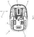
Fig. 4 shows a view from below onto the bottom side 4 of the electronic hand stamp 1. Theprinthead 36 is positioned essentially centred between theprisms target LEDs optical motion detector 35, which is in principle similar to detectors used for optical computer mice. During printing, the electronic hand stamp 1 is moved in one or the other direction along an essentially linear axis ofmotion 37. A row of inkjet nozzles of theprinthead 36 is arranged perpendicular to the axis ofmotion 37. Therollers 38 guide and help to maintain a straight path of movement during printing, i.e. along the axis ofmotion 37.
Claims (14)
- Electronic hand stamp (1) comprising:an inkjet printhead with nozzles directed toward a bottom side (4) of the electronic hand stamp (1),a control circuit (30) anda motion detector,wherein the control circuit (30) is connected to the motion detector and to the inkjet printhead and configured to control the inkjet printhead in response to readings received from the motion detector,characterized in that the electronic hand stamp (1) comprises at least four indicator LEDs (10-17) connected to the control circuit (30), wherein at least one of the at least four indicator LEDs (10-17) is arranged on every side perpendicular to the bottom side (4) of the electronic hand stamp (1).
- Electronic hand stamp (1) according to claim 1, characterized in that the electronic hand stamp (1) comprises at least six indicator LEDs (10-17), preferably at least eight indicator LEDs (10-17), connected to the control circuit (30).
- Electronic hand stamp (1) according to claim 1 or 2, characterized in that the indicator LEDs (10-17) are multicolour LEDs, wherein the control circuit (30) is configured to control the indicator LEDs (10-17) to glow in the same colour, in particular either simultaneously or time-delayed.
- Electronic hand stamp (1) according to one of the preceding claims, characterized in that the electronic hand stamp (1) comprises a diffuser (9), wherein at least two indicator LEDs (10-17) are optically connected with the diffuser (9).
- Electronic hand stamp (1) according to claim 4, characterized in that the distance between the indicator LEDs (10-17) is small enough that the brightness of the LED-light through the diffuser (9) is essentially homogeneous.
- Electronic hand stamp (1) according to claim 4 or 5, characterized in that all of the at least four indicator LEDs (10-17) are optically connected with the diffuser (9), in particular the diffuser (9) circumferentially surrounds the electronic hand stamp (1).
- Electronic hand stamp (1) according to one of the preceding claims, characterized in that the at least four indicator LEDs (10-17) are arranged on two or more printed circuit boards (26-29) .
- Electronic hand stamp (1) according to one of the preceding claims, characterized in that at least one target LED (31, 32) for illuminating a print area adjacent the printhead is connected to the control circuit (30), preferably at least two target LEDs (31, 32).
- Electronic hand stamp (1) according to claim 8, characterized in that the at least two target LEDs (31, 32) are connected to the control circuit (30), wherein the control circuit (30) is configured to switch on at least one target LED (31; 32) on one of the sides of the printhead, preferably the side corresponding to the direction in which the printhead is being moved.
- Electronic hand stamp (1) according to claim 8 or 9, characterized in that the at least one target LED (31, 32) is optically connected to a prism (33, 34) for deflecting light emitted by the at least one target LED (31, 32) to the print area.
- Method for controlling an electronic hand stamp (1) according to claim 1, characterized by controlling the at least four indicator LEDs (10-17) in an interdependent fashion.
- Method according to claim 11, characterized by controlling the at least four indicator LEDs (10-17) to simultaneously glow in a predefined colour to indicate an operating status of the electronic hand stamp (1).
- Method according to claim 11, characterized by controlling the at least four indicator LEDs (10-17) to glow in a time-delayed fashion and in order of their circumferential arrangement, preferably for at least one turn, to indicate an ongoing operation.
- Method for controlling an electronic hand stamp (1) according to claim 9, characterized by switching on at least one target LED (31; 32) on one of the sides of the printhead, preferably the side corresponding to the direction in which the printhead is being moved, when a direction of movement of the electronic hand stamp (1) is detected, and switching off the other target LEDs (32; 32).
Priority Applications (13)
| Application Number | Priority Date | Filing Date | Title |
|---|---|---|---|
| EP18179493.4A EP3587127A1 (en) | 2018-06-25 | 2018-06-25 | Electronic hand stamp |
| MX2020013180A MX2020013180A (en) | 2018-06-25 | 2019-06-25 | Electronic hand stamp. |
| CA3099829A CA3099829A1 (en) | 2018-06-25 | 2019-06-25 | Electronic hand stamp |
| ARP190101760A AR115622A1 (en) | 2018-06-25 | 2019-06-25 | ELECTRONIC MANUAL SEAL |
| US17/254,184 US11642904B2 (en) | 2018-06-25 | 2019-06-25 | Electronic hand stamp |
| CN201980040296.0A CN112313082B (en) | 2018-06-25 | 2019-06-25 | Electronic fingerprint |
| AU2019294966A AU2019294966A1 (en) | 2018-06-25 | 2019-06-25 | Electronic hand stamp |
| EP19732059.1A EP3810428B1 (en) | 2018-06-25 | 2019-06-25 | Electronic hand stamp |
| KR1020207036236A KR20210024466A (en) | 2018-06-25 | 2019-06-25 | Electronic hand stamp |
| JP2020570884A JP7338837B2 (en) | 2018-06-25 | 2019-06-25 | electronic hand stamp |
| BR112020026158-0A BR112020026158A2 (en) | 2018-06-25 | 2019-06-25 | ELECTRONIC HAND STAMP |
| PCT/EP2019/066805 WO2020002319A1 (en) | 2018-06-25 | 2019-06-25 | Electronic hand stamp |
| ES19732059T ES2940587T3 (en) | 2018-06-25 | 2019-06-25 | electronic hand stamp |
Applications Claiming Priority (1)
| Application Number | Priority Date | Filing Date | Title |
|---|---|---|---|
| EP18179493.4A EP3587127A1 (en) | 2018-06-25 | 2018-06-25 | Electronic hand stamp |
Publications (1)
| Publication Number | Publication Date |
|---|---|
| EP3587127A1 true EP3587127A1 (en) | 2020-01-01 |
Family
ID=62778755
Family Applications (2)
| Application Number | Title | Priority Date | Filing Date |
|---|---|---|---|
| EP18179493.4A Withdrawn EP3587127A1 (en) | 2018-06-25 | 2018-06-25 | Electronic hand stamp |
| EP19732059.1A Active EP3810428B1 (en) | 2018-06-25 | 2019-06-25 | Electronic hand stamp |
Family Applications After (1)
| Application Number | Title | Priority Date | Filing Date |
|---|---|---|---|
| EP19732059.1A Active EP3810428B1 (en) | 2018-06-25 | 2019-06-25 | Electronic hand stamp |
Country Status (12)
| Country | Link |
|---|---|
| US (1) | US11642904B2 (en) |
| EP (2) | EP3587127A1 (en) |
| JP (1) | JP7338837B2 (en) |
| KR (1) | KR20210024466A (en) |
| CN (1) | CN112313082B (en) |
| AR (1) | AR115622A1 (en) |
| AU (1) | AU2019294966A1 (en) |
| BR (1) | BR112020026158A2 (en) |
| CA (1) | CA3099829A1 (en) |
| ES (1) | ES2940587T3 (en) |
| MX (1) | MX2020013180A (en) |
| WO (1) | WO2020002319A1 (en) |
Families Citing this family (2)
| Publication number | Priority date | Publication date | Assignee | Title |
|---|---|---|---|---|
| JP2021021052A (en) * | 2019-07-30 | 2021-02-18 | 日本ポリエチレン株式会社 | Resin composition, easily tearable film, and packaging material |
| CN110525023B (en) * | 2019-09-26 | 2021-01-22 | 义乌泰乐机械设备有限公司 | High-frequency suspension thermal transfer printer without pressure |
Citations (7)
| Publication number | Priority date | Publication date | Assignee | Title |
|---|---|---|---|---|
| US4947262A (en) | 1986-06-11 | 1990-08-07 | Casio Computer Co., Ltd. | Hand-held manually sweeping printing apparatus |
| US20030106447A1 (en) * | 2000-07-06 | 2003-06-12 | Alex Walling | Electronic stamp |
| DE10353875A1 (en) | 2002-11-28 | 2004-09-23 | Konrad, Hilmar, Dipl.-Ing. | Hand operated printing device for labels, with scan unit to read existing text, symbol and/or bar-code to copy onto labels for similar items |
| US20050088683A1 (en) * | 2002-02-13 | 2005-04-28 | Kia Silverbrook | Manually operable printer-scanner |
| US20070147930A1 (en) * | 2005-12-27 | 2007-06-28 | Sogra Nishath | Light guides to assist in movement of a handheld printing device |
| DE102005014227B4 (en) | 2005-03-30 | 2007-09-06 | Ernst Reiner Gmbh & Co. Kg, Feinmechanik Und Apparatebau | printing device |
| US7481528B2 (en) * | 2003-05-02 | 2009-01-27 | Rd & Ip, L.L.C. | Digital printing toy |
Family Cites Families (16)
| Publication number | Priority date | Publication date | Assignee | Title |
|---|---|---|---|---|
| NL8902699A (en) * | 1989-11-01 | 1991-06-03 | Product Partners | SEALING MACHINE. |
| JPH09118048A (en) * | 1995-10-25 | 1997-05-06 | Brother Ind Ltd | Manual printing apparatus |
| US5634730A (en) * | 1995-11-06 | 1997-06-03 | Bobry; Howard H. | Hand-held electronic printer |
| JP2001014570A (en) | 1999-04-28 | 2001-01-19 | Nittan Co Ltd | Fire sensor |
| JP2002264396A (en) * | 2001-03-06 | 2002-09-18 | Sony Corp | Imaging apparatus |
| AUPS048402A0 (en) | 2002-02-13 | 2002-03-07 | Silverbrook Research Pty. Ltd. | Methods and systems (ap43) |
| US7682017B2 (en) * | 2006-05-10 | 2010-03-23 | Lexmark International, Inc. | Handheld printer minimizing printing defects |
| US7787145B2 (en) * | 2006-06-29 | 2010-08-31 | Lexmark International, Inc. | Methods for improving print quality in a hand-held printer |
| CN202195364U (en) | 2011-07-25 | 2012-04-18 | 松下电工·万宝电器(广州)有限公司 | Indication lamp |
| CN103371718A (en) | 2012-04-13 | 2013-10-30 | 东莞市时唛特电器有限公司 | Water boiler used for indicating working conditions in multidirectional manner |
| CN202698893U (en) | 2012-04-13 | 2013-01-30 | 东莞市时唛特电器有限公司 | Toaster for indicating working conditions in multiple directions |
| CN103697388B (en) * | 2012-09-28 | 2016-02-03 | 重庆长安汽车股份有限公司 | A kind of light guide lamp for automobile |
| WO2014087278A1 (en) | 2012-12-03 | 2014-06-12 | Koninklijke Philips N.V. | Light emitting arrangement using light guides. |
| JP6155240B2 (en) * | 2014-09-22 | 2017-06-28 | 富士フイルム株式会社 | Electronic cassette and electronic cassette system |
| JP6506080B2 (en) * | 2015-04-02 | 2019-04-24 | 富士通コンポーネント株式会社 | Portable printing device |
| CN206259180U (en) * | 2016-11-15 | 2017-06-16 | 宁夏银星吴忠仪表流体控制有限公司 | YE housing with indicator lamp |
-
2018
- 2018-06-25 EP EP18179493.4A patent/EP3587127A1/en not_active Withdrawn
-
2019
- 2019-06-25 WO PCT/EP2019/066805 patent/WO2020002319A1/en unknown
- 2019-06-25 JP JP2020570884A patent/JP7338837B2/en active Active
- 2019-06-25 KR KR1020207036236A patent/KR20210024466A/en unknown
- 2019-06-25 US US17/254,184 patent/US11642904B2/en active Active
- 2019-06-25 CA CA3099829A patent/CA3099829A1/en not_active Abandoned
- 2019-06-25 ES ES19732059T patent/ES2940587T3/en active Active
- 2019-06-25 MX MX2020013180A patent/MX2020013180A/en unknown
- 2019-06-25 AU AU2019294966A patent/AU2019294966A1/en not_active Abandoned
- 2019-06-25 AR ARP190101760A patent/AR115622A1/en unknown
- 2019-06-25 EP EP19732059.1A patent/EP3810428B1/en active Active
- 2019-06-25 CN CN201980040296.0A patent/CN112313082B/en active Active
- 2019-06-25 BR BR112020026158-0A patent/BR112020026158A2/en unknown
Patent Citations (8)
| Publication number | Priority date | Publication date | Assignee | Title |
|---|---|---|---|---|
| US4947262A (en) | 1986-06-11 | 1990-08-07 | Casio Computer Co., Ltd. | Hand-held manually sweeping printing apparatus |
| US20030106447A1 (en) * | 2000-07-06 | 2003-06-12 | Alex Walling | Electronic stamp |
| US20050088683A1 (en) * | 2002-02-13 | 2005-04-28 | Kia Silverbrook | Manually operable printer-scanner |
| US7426050B2 (en) | 2002-02-13 | 2008-09-16 | Silverbrook Research Pty Ltd | Manually operable printer-scanner |
| DE10353875A1 (en) | 2002-11-28 | 2004-09-23 | Konrad, Hilmar, Dipl.-Ing. | Hand operated printing device for labels, with scan unit to read existing text, symbol and/or bar-code to copy onto labels for similar items |
| US7481528B2 (en) * | 2003-05-02 | 2009-01-27 | Rd & Ip, L.L.C. | Digital printing toy |
| DE102005014227B4 (en) | 2005-03-30 | 2007-09-06 | Ernst Reiner Gmbh & Co. Kg, Feinmechanik Und Apparatebau | printing device |
| US20070147930A1 (en) * | 2005-12-27 | 2007-06-28 | Sogra Nishath | Light guides to assist in movement of a handheld printing device |
Also Published As
| Publication number | Publication date |
|---|---|
| BR112020026158A2 (en) | 2021-03-16 |
| JP2021528284A (en) | 2021-10-21 |
| KR20210024466A (en) | 2021-03-05 |
| EP3810428B1 (en) | 2023-03-08 |
| WO2020002319A1 (en) | 2020-01-02 |
| EP3810428A1 (en) | 2021-04-28 |
| US20210122176A1 (en) | 2021-04-29 |
| JP7338837B2 (en) | 2023-09-05 |
| AU2019294966A1 (en) | 2020-12-03 |
| CN112313082B (en) | 2022-11-22 |
| CA3099829A1 (en) | 2020-01-02 |
| MX2020013180A (en) | 2021-05-27 |
| AR115622A1 (en) | 2021-02-10 |
| CN112313082A (en) | 2021-02-02 |
| US11642904B2 (en) | 2023-05-09 |
| ES2940587T3 (en) | 2023-05-09 |
Similar Documents
| Publication | Publication Date | Title |
|---|---|---|
| EP3810428B1 (en) | Electronic hand stamp | |
| US6422675B1 (en) | Printing apparatus | |
| EP0898412B1 (en) | Image reading apparatus | |
| US8829481B2 (en) | Top of form sensor | |
| US7766452B2 (en) | Ink jet recording head, liquid storage container and ink jet recording apparatus | |
| US7285771B2 (en) | Optical sensor | |
| RU2786360C2 (en) | Electronic hand stamp | |
| JP2008012748A (en) | Guide member of manual type recorder and recording method of manual type recorder | |
| US20020089554A1 (en) | System and method for conveying printer status information | |
| JP7336837B2 (en) | Printer inspection method and printer | |
| JP4994050B2 (en) | Encoder sheet, position detection device, image forming device | |
| JP2006116787A (en) | Ink tank, apparatus for mounting ink tank and inkjet recording apparatus | |
| KR101173609B1 (en) | Indicator using light guide plate | |
| CN103770470B (en) | There is optical pickocff to identify the ink loader of solid ink stick | |
| CN110293776B (en) | Printing unit, printing device, and capping device | |
| JP5750292B2 (en) | Electronic blackboard equipment | |
| JP2017170761A (en) | Printing device, printing method and program | |
| JPWO2020002319A5 (en) | ||
| JP2004336502A (en) | Automatic contract device | |
| WO2019017948A1 (en) | Print cartridges with light pipes and touch sensitive circuits | |
| JP2004268300A (en) | Ink jet recorder | |
| JP2014024263A (en) | Tape cassette | |
| JP2005178059A (en) | Image forming apparatus | |
| JP2006007540A (en) | Thermal transfer printer |
Legal Events
| Date | Code | Title | Description |
|---|---|---|---|
| PUAI | Public reference made under article 153(3) epc to a published international application that has entered the european phase |
Free format text: ORIGINAL CODE: 0009012 |
|
| STAA | Information on the status of an ep patent application or granted ep patent |
Free format text: STATUS: THE APPLICATION HAS BEEN PUBLISHED |
|
| AK | Designated contracting states |
Kind code of ref document: A1 Designated state(s): AL AT BE BG CH CY CZ DE DK EE ES FI FR GB GR HR HU IE IS IT LI LT LU LV MC MK MT NL NO PL PT RO RS SE SI SK SM TR |
|
| AX | Request for extension of the european patent |
Extension state: BA ME |
|
| STAA | Information on the status of an ep patent application or granted ep patent |
Free format text: STATUS: THE APPLICATION IS DEEMED TO BE WITHDRAWN |
|
| 18D | Application deemed to be withdrawn |
Effective date: 20200702 |