EP3587042A1 - Method, apparatus and system for determining a trajectory of a robot's end effector - Google Patents
Method, apparatus and system for determining a trajectory of a robot's end effector Download PDFInfo
- Publication number
- EP3587042A1 EP3587042A1 EP18179535.2A EP18179535A EP3587042A1 EP 3587042 A1 EP3587042 A1 EP 3587042A1 EP 18179535 A EP18179535 A EP 18179535A EP 3587042 A1 EP3587042 A1 EP 3587042A1
- Authority
- EP
- European Patent Office
- Prior art keywords
- trajectory
- end effector
- collision
- point
- vector
- Prior art date
- Legal status (The legal status is an assumption and is not a legal conclusion. Google has not performed a legal analysis and makes no representation as to the accuracy of the status listed.)
- Granted
Links
Images



Classifications
-
- B—PERFORMING OPERATIONS; TRANSPORTING
- B25—HAND TOOLS; PORTABLE POWER-DRIVEN TOOLS; MANIPULATORS
- B25J—MANIPULATORS; CHAMBERS PROVIDED WITH MANIPULATION DEVICES
- B25J9/00—Program-controlled manipulators
- B25J9/16—Program controls
- B25J9/1674—Program controls characterised by safety, monitoring, diagnostic
- B25J9/1676—Avoiding collision or forbidden zones
-
- B—PERFORMING OPERATIONS; TRANSPORTING
- B25—HAND TOOLS; PORTABLE POWER-DRIVEN TOOLS; MANIPULATORS
- B25J—MANIPULATORS; CHAMBERS PROVIDED WITH MANIPULATION DEVICES
- B25J9/00—Program-controlled manipulators
- B25J9/16—Program controls
- B25J9/1628—Program controls characterised by the control loop
- B25J9/1653—Program controls characterised by the control loop parameters identification, estimation, stiffness, accuracy, error analysis
-
- B—PERFORMING OPERATIONS; TRANSPORTING
- B25—HAND TOOLS; PORTABLE POWER-DRIVEN TOOLS; MANIPULATORS
- B25J—MANIPULATORS; CHAMBERS PROVIDED WITH MANIPULATION DEVICES
- B25J9/00—Program-controlled manipulators
- B25J9/16—Program controls
- B25J9/1656—Program controls characterised by programming, planning systems for manipulators
- B25J9/1664—Program controls characterised by programming, planning systems for manipulators characterised by motion, path, trajectory planning
- B25J9/1666—Avoiding collision or forbidden zones
-
- G—PHYSICS
- G05—CONTROLLING; REGULATING
- G05B—CONTROL OR REGULATING SYSTEMS IN GENERAL; FUNCTIONAL ELEMENTS OF SUCH SYSTEMS; MONITORING OR TESTING ARRANGEMENTS FOR SUCH SYSTEMS OR ELEMENTS
- G05B19/00—Program-control systems
- G05B19/02—Program-control systems electric
- G05B19/18—Numerical control [NC], i.e. automatically operating machines, in particular machine tools, e.g. in a manufacturing environment, so as to execute positioning, movement or co-ordinated operations by means of program data in numerical form
- G05B19/406—Numerical control [NC], i.e. automatically operating machines, in particular machine tools, e.g. in a manufacturing environment, so as to execute positioning, movement or co-ordinated operations by means of program data in numerical form characterised by monitoring or safety
- G05B19/4061—Avoiding collision or forbidden zones
-
- G—PHYSICS
- G05—CONTROLLING; REGULATING
- G05B—CONTROL OR REGULATING SYSTEMS IN GENERAL; FUNCTIONAL ELEMENTS OF SUCH SYSTEMS; MONITORING OR TESTING ARRANGEMENTS FOR SUCH SYSTEMS OR ELEMENTS
- G05B2219/00—Program-control systems
- G05B2219/30—Nc systems
- G05B2219/49—Nc machine tool, till multiple
- G05B2219/49147—Retract on collision with moving object, tool follows, yields to object
-
- G—PHYSICS
- G05—CONTROLLING; REGULATING
- G05B—CONTROL OR REGULATING SYSTEMS IN GENERAL; FUNCTIONAL ELEMENTS OF SUCH SYSTEMS; MONITORING OR TESTING ARRANGEMENTS FOR SUCH SYSTEMS OR ELEMENTS
- G05B2219/00—Program-control systems
- G05B2219/30—Nc systems
- G05B2219/50—Machine tool, machine tool null till machine tool work handling
- G05B2219/50108—Retract tool stepwise, same path, until safe boundary reached, then quick retract
-
- G—PHYSICS
- G05—CONTROLLING; REGULATING
- G05B—CONTROL OR REGULATING SYSTEMS IN GENERAL; FUNCTIONAL ELEMENTS OF SUCH SYSTEMS; MONITORING OR TESTING ARRANGEMENTS FOR SUCH SYSTEMS OR ELEMENTS
- G05B2219/00—Program-control systems
- G05B2219/30—Nc systems
- G05B2219/50—Machine tool, machine tool null till machine tool work handling
- G05B2219/50109—Soft approach, engage, retract, escape, withdraw path for tool to workpiece
Definitions
- the disclosure relates to robot field, and more particularly, to a method, apparatus and system for determining a trajectory of a robot's end effector.
- the provided robot collision processing solutions are collision detection solutions based on current or torque, and the work performed by the robot is stopped after a collision is detected. These solutions do not fundamentally address potential losses due to collisions.
- the present application provides a method and apparatus for determining a trajectory of a robot's end effector.
- a trajectory of the end effector after the collision is determined based on a collision force of the end effector caused by the collision and a recorded trajectory of the end effector before the collision, and the end effector is controlled to move based on the determined trajectory, so that an efficient protection of the robot may be achieved.
- a method of determining a trajectory of a robot's end effector comprises: obtaining a collision force of a robot's end effector caused by a collision of the end effector when the collision is detected; and determining a second trajectory of the end effector based on the obtained collision force of the end effector and a recorded first trajectory of the end effector, wherein the first trajectory is a trajectory before the collision, and the second trajectory is a trajectory after the collision.
- the end effector is modeled as an impedance control model, and determining a second trajectory of the end effector based on the obtained collision force of the end effector and a recorded first trajectory of the end effector may comprise: determining the second trajectory of the end effector using the impedance control model, based on the obtained collision force and the recorded first trajectory of the end effector.
- each trajectory point of the trajectory has trajectory information including a position vector, a velocity vector of each trajectory point, and an acceleration vector of the trajectory point
- the method may further comprise: configuring the inertia matrix, the damping matrix, and the stiffness matrix of the end effector under the impedance control model.
- the first trajectory is composed of discrete trajectory points (P 1 , P 2 , together., P M ), and determining a second trajectory of the end effector based on the obtained collision force of the end effector and a recorded first trajectory of the end effector may comprise: obtaining the trajectory information of each discrete trajectory point (P 1 , P 2 , ........, P M ) on the recorded first trajectory; determining a displacement vector, a velocity vector and an acceleration vector of the end effector caused by the collision force using the impedance control model, based on the obtained collision force; and determining trajectory information of each discrete trajectory point (P 1 ', P 2 ', . «, P N ') on the second trajectory, based on the obtained trajectory information of each discrete trajectory point (P 1 , P 2 , . «,P M ) on the first trajectory and the displacement vector, the velocity vector and the acceleration vector of the end effector caused by the collision force.
- determining trajectory information of each discrete trajectory point on the second trajectory may comprise: obtaining an inverse discrete trajectory point arrangement (P M , P M-1 ,... P 1 ) of the first motion trajectory by inversely arranging the discrete trajectory points (P 1 , P 2 , ........, P M ) on the first trajectory; and determining the trajectory information of each discrete trajectory point (P 1 ', P 2 ', . «, P N ') on the second trajectory one by one, based on the trajectory information of each discrete trajectory point (P M , P M-1 ,...
- the method may comprise: controlling the end effector to move based on the determined second trajectory.
- the second trajectory is composed of discrete trajectory points
- controlling the end effector to move based on the determined second trajectory may comprise: controlling the end effector to move according to the determined trajectory information of each discrete trajectory point on the second trajectory.
- an apparatus for determining a trajectory of a robot's end effector may comprise: a force obtaining unit for obtaining a collision force of a robot's end effector caused by a collision of the end effector when the collision is detected; and a trajectory determining unit for determining a second trajectory of the end effector based on the obtained collision force of the end effector and a recorded first trajectory of the end effector, wherein the first trajectory is a trajectory before the collision, and the second trajectory is a trajectory after the collision.
- the end effector is modeled as an impedance control model
- the trajectory determining unit may be configured to: determine the second trajectory of the end effector using the impedance control model, based on the obtained collision force and the recorded first trajectory of the impedance control model.
- each trajectory point of the trajectory has trajectory information including a position vector, a velocity vector of the trajectory point, and an acceleration vector of the trajectory point
- the apparatus may further comprise: a configuring unit for configuring the inertia matrix, the damping matrix, and the stiffness matrix of the end effector under the impedance control model.
- the first trajectory is composed of discrete trajectory points (P 1 , P 2 , ........, P M ), and the trajectory determining unit may comprise: an obtaining module for obtaining the trajectory information of each discrete trajectory point (P 1 , P 2 , . «, P M ) on the recorded first trajectory; a first determining module for determining a displacement vector, a velocity vector and an acceleration vector of the end effector caused by the collision force using the impedance control model, based on the obtained collision force; and a second determining module for determining trajectory information of each discrete trajectory point (P 1 ', P 2 ', . «, P N ') on the second trajectory, based on the obtained trajectory information of each discrete trajectory point (P 1 , P 2 , . «, P M ) on the first trajectory and the displacement vector, the velocity vector and the acceleration vector of the end effector caused by the collision force.
- the second determining module may be configured to: obtain an inverse discrete trajectory point arrangement (P M , P M-2 ,.... P 1 ) of the first motion trajectory by inversely arranging the discrete trajectory points (P 1 , P 2 , ........, P M ) on the first trajectory; and determine the trajectory information of each discrete trajectory point (P 1 ', P 2 ', . «, P N ') on the second trajectory one by one, based on the trajectory information of each discrete trajectory point (P M , P M-1 ,...
- the apparatus may comprise: a controlling unit for controlling the end effector to move based on the determined second trajectory.
- a computer device for determining a trajectory of a robot's end effector comprising: one or more processors; and a memory coupled to the one or more processors, for storing computer-executable instructions that, when executed, cause the one or more processors to perform the method for determining a trajectory of a robot's end effector as above.
- a non-transitory machine-readable medium having computer-executable instructions to cause a machine to perform the method for determining a trajectory of a robot's end effector as above.
- a system for determining a trajectory of a robot's end effector may comprise: a collision force detecting apparatus for detecting a collision force of a robot's end effector caused by a collision of the end effector when the collision is detected; and an apparatus for determining a trajectory of a robot's end effector as above.
- a trajectory of the end effector after the collision is determined based on a detected collision force of the end effector caused by the collision and a recorded trajectory of the end effector before the collision, and thus protection of the robot and its work environment may be significantly improved.
- the movement of the robot after the collision may be controllable.
- impedance control model means a dynamic mathematical model between the robot's external force and the robot's position, velocity, and acceleration.
- the impedance represents the resistance trend of the robot when the robot is subjected to external forces.
- a solution for determining the following trajectory of a robot's end effector after a collision is provided, and thus the deviation of the trajectory due to the collision may be minimized and the robot may restore to the original trajectory as soon as possible, by controlling the trajectory of the end effector after collision.
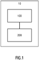
- FIG. 1 illustrates a block diagram of a system for determining a trajectory of a robot's end effector (Hereinafter referred to simply as a trajectory determining system 10) according to an embodiment of the subject matter.
- the trajectory determining system 10 includes a collision force detecting apparatus 100 for detecting a collision force of a robot's end effector caused by a collision of the end effector when the collision is detected, that is, the collision between the end effector and other robots, operators, obstacle, or processed objects (e.g., processed workpieces) in the robot's environment.
- the detected collision force is a vector having a direction and a magnitude.
- the collision force detecting device 100 may be any type of force detecting device, such as a force sensor or the like.
- the trajectory determining system 10 further includes an apparatus 200 (hereinafter simply referred to as a "trajectory determining apparatus 200") for determining a trajectory of a robot's end effector, so that the robot is caused to move along the determined trajectory through a robot controller.
- the trajectory determining system 10 may be a part of the robot controller, or a separate system.
- the trajectory determining apparatus 200 is coupled or otherwise connected or communicated to the collision force detecting apparatus 100 in a wired or wireless manner, and is used to determine the trajectory of the end effector after the collision, based on the subjected collision force of the end effector detected by the collision force detecting device 100 and the recorded trajectory of the end effector before the collision.
- FIG. 2 illustrates an example block diagram of a trajectory determining apparatus 200 according to an embodiment of the subject matter.
- trajectory determining apparatus 200 may include a force obtaining unit 210.
- the force obtaining unit 210 is configured to obtain the detected collision force of the end effector from the collision force detecting apparatus 100.
- the force obtaining unit 210 may communicate with the collision force detecting apparatus 100 by means of active acquisition or passive reception to obtain the collision force suffered by the end effector.
- the communication between the force obtaining unit 210 and the collision force detecting apparatus 100 may be a wired communication or a wireless communication.
- the trajectory determining apparatus 200 may further include a trajectory determining unit 220.
- the trajectory determining unit 220 is configured to determine a second trajectory of the end effector based on the obtained collision force and the recorded first trajectory of the end effector.
- the first trajectory is the trajectory of the end effector before the collision
- the second trajectory is the trajectory of the end effector after the collision, that is, the planned trajectory of the end effector after the collision.
- the second trajectory is a controllable trajectory along which the robot is desired to move after the collision, rather than an uncontrollable spontaneous trajectory.
- Each trajectory point of the first and second trajectory has trajectory information including a position vector, a velocity vector, and an acceleration vector of the trajectory point.
- the trajectory determining apparatus 200 may further include a recording unit 230.
- the recording unit 230 is configured to record the first trajectory of the end effector.
- the recording unit 230 records trajectory information of the first trajectory.
- the end effector is modeled as an impedance control model.
- the trajectory determining apparatus 200 may further include a configuration unit 240.
- the configuration unit 240 configured to configure the inertia matrix, the damping matrix, and the stiffness matrix of the end effector under the impedance control model.
- the trajectory determining unit 220 determines the second trajectory of the end effector using the impedance control model, based on the obtained collision force and the recorded first trajectory of the end effector.
- the first trajectory and the second trajectory may be a set of discrete trajectory points.
- the first trajectory is composed of discrete trajectory points P 1 , P 2 , whil, P M , where PI is the start trajectory point, and P M is the end trajectory point.
- the second trajectory is composed of discrete trajectory points P 1 ', P 2 ', whil, P N ', where P 1 ' is the start trajectory point and P N ' is the end trajectory point.
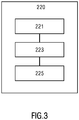
- the trajectory determining unit 220 may include an obtaining module 221, a first determining module 223, and a second determining module 225.
- the second determining module 225 determines trajectory information of each discrete trajectory point (P 1 ', P 2 ', administrat., P N ') on the second trajectory, based on the obtained trajectory information of each discrete trajectory point (P 1 , P 2 , . «, P M ) on the first trajectory and the displacement vector, the velocity vector and the acceleration vector of the end effector caused by the collision force.
- the second determining module 225 in determination of trajectory information of each discrete trajectory point (P 1 ', P 2 ', whil., P N ') on the second trajectory, the second determining module 225 first obtains an inverse discrete trajectory point arrangement (P M , P M-1 ,... P 1 ) of the first trajectory by inversely arranging the discrete trajectory points (P 1 , P 2 , ........, P M ) on the first trajectory. Then, the second determining unit 225 determines the trajectory information of each discrete trajectory point (P 1 ', P 2 ', ........, P N ') on the second trajectory one by one, based on the trajectory information of each discrete trajectory point (P M , P M-1 ,...
- the end trajectory point on the second trajectory is determined by calculating the trajectory distance between the current trajectory point and the start trajectory point P 1 ' (i.e., the end trajectory point P M of the first motion trajectory) of the second trajectory, and then further calculating the difference between the calculated trajectory distance and the displacement distance
- the trajectory distance between the current trajectory point Pi' of the second trajectory and the start trajectory point P 1 ' (i.e., the end trajectory point P M of the first motion trajectory) of the second trajectory is obtained by summing the vector distances between all two adjacent trajectory points of the trajectory points P 1 ', P 2 ', ..., Pi'.
- the calculation starts by taking the trajectory point P 1 ' as the current trajectory point. At this time, the trajectory distance is 0, which does not satisfy the determination condition that the aforementioned difference is smaller than the predetermined threshold. Then, the current trajectory point is moved to the trajectory point P 2 ', and then the vector distance ⁇ P 2 between P 1 ' and P 2 ' is calculated as the trajectory distance between the trajectory points P 2 ' and P 1 ' as above, and then the calculated trajectory distance is compared with the displacement distance
- the current trajectory point is moved to the trajectory point P 3 ', and then the vector distance ⁇ P 3 between the trajectory points P 2 ' and P 3 ' is calculated as above. Then, the sum of the vector distances ⁇ P 2 and ⁇ P 3 is taken as the trajectory distance between the trajectory points P 3 'and P 1 '. If the difference is smaller than the predetermined threshold ⁇ , the trajectory point P 3 ' is the end trajectory point of the second trajectory. Otherwise, the current trajectory point is moved to the trajectory point P 4 ', as similarly calculated and compared as above, until the end trajectory point of the second trajectory is determined.
- the second determining module 225 determines the trajectory information of each discrete trajectory point on the second trajectory one by one, the position vector of each discrete trajectory point is determined to be same as the position vector of the corresponding discrete trajectory point in the reverse discrete trajectory point arrangement, and the directions of the velocity vector and the acceleration vector of each discrete trajectory point on the second trajectory are determined to be opposite to the directions of the velocity vector and the acceleration vector of the corresponding discrete trajectory point in the reverse discrete trajectory point arrangement. In this way, when the movement of the robot along the second trajectory is finished (i.e., the movement along the second trajectory is stopped), there is no need to perform additional trajectory planning again, and the movement may be quickly restored based on the original collision-free trajectory. Further, the second determining module 225 set the velocity vector and the acceleration vector of the end trajectory point of the second trajectory to be zero.
- V i ′ ⁇ X ⁇ i + X ⁇ M ⁇ i + 1 X ⁇ i + X ⁇ M ⁇ i + 1 ⁇ V lim it V lim it X ⁇ i + X ⁇ M ⁇ i + 1 ⁇ V lim it ,
- a i ′ ⁇ X ⁇ i + X ⁇ M ⁇ i + 1 X ⁇ i + X ⁇ M ⁇ i + 1 ⁇ A lim it A lim it X ⁇ i + X ⁇ M ⁇ i + 1 ⁇ A lim it wherein V lim it is a velocity threshold, and A lim it is an acceleration threshold.
- V lim it and A lim it are factory setting. Once V lim it and A lim it are set, the values thereof are usually invariable.
- the trajectory (i.e., the first trajectory) of the end effector is a trajectory composed of discrete trajectory points P 1 , P 2 , whil, P M .
- the trajectory information i.e., a position vector, a velocity vector, and an acceleration vector
- the second determining module 225 in the trajectory determining apparatus 200 determines the trajectory information of each trajectory point on the second trajectory one by one, based on trajectory information of each discrete trajectory point P 1 , P 2 ,..., P M and the obtained displacement vector X, velocity vector ⁇ and acceleration vector ⁇ .
- the second determining module 225 determines that the position vector of a start trajectory point P 1 ' of the second trajectory is same as the position vector of the end trajectory point P M on the first trajectory, and the directions of the velocity vector and the acceleration vector of the start trajectory point P 1 ' of the second trajectory are opposite to the directions of the velocity vector and the acceleration vector of the end trajectory point P M on the first trajectory.
- V 1 ′ ⁇ X ⁇ + X ⁇ M X ⁇ + X ⁇ M ⁇ V lim it V lim it X ⁇ + X ⁇ M ⁇ V lim it
- a 1 ′ ⁇ X ⁇ + X ⁇ M X ⁇ + X ⁇ M ⁇ A lim it A lim it X ⁇ + X ⁇ M ⁇ A lim it , wherein V lim it is a velocity threshold, and A lim it is an acceleration threshold.
- the second trajectory point of the second trajectory is then determined.
- the second determining module 225 determines that the position vector of the second trajectory point P 2 ' of the second trajectory is same as the position vector of the trajectory point P M-1 on the first trajectory, and the directions of the velocity vector and the acceleration vector of the second trajectory point P 2 ' of the second trajectory are opposite to the directions of the velocity vector and the acceleration vector of the trajectory point P M-1 on the first trajectory.
- V 2 ′ ⁇ X ⁇ 2 + X ⁇ M ⁇ 1 X ⁇ 2 + X ⁇ M ⁇ 1 ⁇ V lim it V lim it X ⁇ 2 + X ⁇ M ⁇ 1 ⁇ V lim it
- a 2 ′ ⁇ X ⁇ 2 + X ⁇ M ⁇ 1 X ⁇ 2 + X ⁇ M ⁇ 1 ⁇ A lim it A lim it X ⁇ 2 + X ⁇ M ⁇ 1 ⁇ A lim it , wherein V lim it is a velocity threshold, and A lim it is an acceleration threshold.
- the second determining module 225 determines that the position vector of the trajectory point Pi' of the second trajectory is same as the position vector of the trajectory point P M-i+1 on the first trajectory, and the directions of the velocity vector and the acceleration vector of the second trajectory point P 1 ' of the second trajectory are opposite to the directions of the velocity vector and the acceleration vector of the trajectory point P M-i+1 on the first trajectory.
- V i ′ ⁇ X ⁇ i + X ⁇ M ⁇ i + 1 X ⁇ i + X ⁇ M ⁇ i + 1 ⁇ V lim it V lim it X ⁇ i + X ⁇ M ⁇ i + 1 ⁇ V lim it ,
- a i ′ ⁇ X ⁇ i + X ⁇ M ⁇ i + 1 X ⁇ i + X ⁇ M ⁇ i + 1 ⁇ A lim it A lim it X ⁇ i + X ⁇ M ⁇ i + 1 ⁇ A lim it , wherein V lim it is a velocity threshold, and A lim it is an acceleration threshold.
- the trajectory determining apparatus 200 may further include a controlling unit 250.
- the controlling unit 250 is configured to control the end effector to move based on the determined second trajectory after the second motion trajectory of the end effector is obtained as above.
- the controlling unit 250 may control the end effector to move according to the determined trajectory information of the discrete trajectory point on the second trajectory.
- FIGS. 1 to 4 The apparatus and system for determining a trajectory of a robot's end effector according to an embodiment of the subject matter are described above with reference to FIGS. 1 to 4 , and a method for determining a trajectory of a robot's end effector according to an embodiment of the subject matter will be described below with reference to FIGS. 5 to 6 .
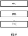
- FIG. 5 illustrates a flowchart of a method for determining a trajectory of a robot's end effector according to an embodiment of the subject matter.
- a force obtaining unit 210 in the trajectory determining apparatus 200 obtains the collision force suffered by the end effector from the collision force detecting apparatus 100.
- the operation in block 510 is similar to the operation of the force obtaining unit 210 described as above with reference to FIG. 2 .
- the trajectory determining unit 220 in the trajectory determining apparatus 200 determines a second trajectory of the end effector based on the obtained collision force of the end effector and a recorded first trajectory of the end effector.
- the operation in block 530 is similar to the operation of the trajectory determining unit 220 described as above with reference to FIG. 2 .
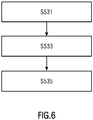
- FIG. 6 illustrates a flowchart of an example process for determining a second trajectory of the end effector based on the obtained collision force and the recorded first trajectory of the end effector in Fig.5 .
- block 531 the trajectory information of each discrete trajectory point on the recorded first trajectory is obtained.
- the operation of block 531 is similar to the operation of the obtaining module 221 described with reference to FIG 3 .
- the trajectory information (i.e., the displacement vector, the velocity vector, and the acceleration vector) of the end effector caused by the collision force is determined using an impedance control model, based on the obtained impact force.
- the operation of block 533 is similar to the operation of the first determining module 223 described as above with reference to FIG 3 .
- the trajectory information of each discrete trajectory point P 1 ', P 2 ', ..., P N ' of the second trajectory is determined based on the obtained trajectory information of each discrete trajectory points P 1 , P 2 , whil, P M on the first trajectory and the determined trajectory information of end effector corresponding to the collision force.
- the operation of block 535 is similar to the operation of the second determining module 225 described as above with reference to FIG.
- controlling the end effector to move based on the determined second trajectory may comprise: after the trajectory information of each discrete trajectory point on the second trajectory are determined, controlling the end effector to move according to the determined trajectory information of the discrete trajectory point on the second trajectory.
- Embodiments of a method, apparatus, and system for determining a trajectory of a robot's end effector according to the present disclosure have been described as above with reference to FIGS. 1 to 6 .
- the above trajectory determining apparatus may be implemented in hardware, software or a combination of hardware and software.
- the trajectory determining apparatus 200 may be implemented using a computing device.
- FIG. 7 illustrates a block diagram of a computer device 700 for determining a trajectory of a robot's end effector according to an embodiment of the subject matter.
- the computing device 700 may include one or more processors 710 that executes one or more computer-readable instructions (i.e., the above elements implemented in software) stored or encoded in a computer-readable storage medium (i.e., memory 720).
- the computer-executable instructions stored in the memory 720 when executed, may cause the one or more processors to: obtain a collision force of a robot's end effector caused by a collision of the end effector when the collision is detected; and determine a second trajectory of the end effector based on the obtained collision force of the end effector and a recorded first trajectory of the end effector, and wherein the first trajectory is a trajectory before the collision, and the second trajectory is a trajectory after the collision.
- the computer-executable instructions stored in the memory 720 when executed, may cause the one or more processors 710 to perform the respective operations or functions as described above with reference to FIGs. 1 to 6 in various embodiments of the subject matter.
- a program product such as a non-transitory machine-readable medium.
- the machine-readable medium may have instructions (i.e., the above elements implemented in software) thereon which, when executed by a machine, cause the machine to perform the operations or functions as described above with reference to FIGs. 1 to 6 in various embodiments of the subject matter.
- a system or apparatus configured with a readable storage medium may be provided, and a software program code for realizing the functions of any of the above embodiments may be stored on the readable storage medium and may be read out and executed by the machine.
- the program code itself read from the readable storage medium may realize the functions of any of the above embodiments, and thus the machine readable code and the readable storage medium storing the machine readable code form part of the present disclosure.
- Examples of the readable storage media may include floppy disks, hard disks, magneto-optical disks, optical disks (such as CD-ROM, CD-R, CD-RW, DVD-ROM, DVD-RAM, DVD-RW, DVD-RW), magnetic tape, non-volatile memory card, and ROM.
- a program code may be downloaded from a server computer or cloud via a communication network.
- the structures of the apparatus described in the foregoing embodiments may be physical structures or logical structures, that is, some units may be implemented by the same physical entity, or some units may be implemented by a plurality of different physical entities, respectively, or may be implemented by some components of a plurality of standalone device together.
- the hardware unit or module may be implemented by mechanical or electrical means.
- a hardware unit, module, or processor may include a permanently dedicated circuitry or logic (e.g., a specialized processor, FPGA, or ASIC) to perform the corresponding operations.
- a hardware unit or processor may also include a programmable logic or circuitry (such as a general-purpose processor or other programmable processor) that may be temporarily set by software to perform the corresponding operations. Specific implementations (mechanical, or dedicated, permanent circuits, or temporarily set up circuits) may be determined based on cost and time considerations.
Landscapes
- Engineering & Computer Science (AREA)
- Robotics (AREA)
- Mechanical Engineering (AREA)
- Human Computer Interaction (AREA)
- Manufacturing & Machinery (AREA)
- Physics & Mathematics (AREA)
- General Physics & Mathematics (AREA)
- Automation & Control Theory (AREA)
- Manipulator (AREA)
- Numerical Control (AREA)
Abstract
Description
- The disclosure relates to robot field, and more particularly, to a method, apparatus and system for determining a trajectory of a robot's end effector.
- With the advancement of robot technology, more and more industries have introduced industrial robots, such as six-axis industrial robots. In the field of industrial robots, in order to achieve a high work efficiency, the robot's moving speed is usually relatively fast, and thus the robot easily collides with its working environment (for example, other robots, operators, objects, processed workpieces). Once a collision occurs, such as a collision between robots or a collision between a robot and a processing object (for example, a processed workpiece), the robot or the processing object may be damaged. An efficient robot collision processing solution will protect the robot and its working environment to the maximum extent, thereby reducing a cost loss caused by the shutdown or component replacement due to the collision.
- So far, the provided robot collision processing solutions are collision detection solutions based on current or torque, and the work performed by the robot is stopped after a collision is detected. These solutions do not fundamentally address potential losses due to collisions.
- In view of the foregoing, the present application provides a method and apparatus for determining a trajectory of a robot's end effector. With the method and apparatus, after a collision of the end effector is detected, a trajectory of the end effector after the collision is determined based on a collision force of the end effector caused by the collision and a recorded trajectory of the end effector before the collision, and the end effector is controlled to move based on the determined trajectory, so that an efficient protection of the robot may be achieved.
- According to an aspect of the subject matter described herein, a method of determining a trajectory of a robot's end effector is provided. The method comprises: obtaining a collision force of a robot's end effector caused by a collision of the end effector when the collision is detected; and determining a second trajectory of the end effector based on the obtained collision force of the end effector and a recorded first trajectory of the end effector, wherein the first trajectory is a trajectory before the collision, and the second trajectory is a trajectory after the collision.
- Preferably, in an example of the above aspect, the end effector is modeled as an impedance control model, and determining a second trajectory of the end effector based on the obtained collision force of the end effector and a recorded first trajectory of the end effector may comprise: determining the second trajectory of the end effector using the impedance control model, based on the obtained collision force and the recorded first trajectory of the end effector.
- Preferably, in an example of the above aspect, each trajectory point of the trajectory has trajectory information including a position vector, a velocity vector of each trajectory point, and an acceleration vector of the trajectory point, and the impedance control model is fcollision = MẌ + BẊ + KK, where f collision is a collision force of the end effector caused by the collision, and X is a displacement vector of the end effector caused by the collision force, Ẋ and Ẍ are the velocity vector and the acceleration vector of the end effector caused by the collision force, respectively, M is an inertia matrix of the end effector, B is a damping matrix of the end effector, and K is a stiffness matrix of the end effector.
- Preferably, in an example of the above aspect, the method may further comprise: configuring the inertia matrix, the damping matrix, and the stiffness matrix of the end effector under the impedance control model.
- Preferably, in an example of the above aspect, the first trajectory is composed of discrete trajectory points (P1, P2, ......., PM), and determining a second trajectory of the end effector based on the obtained collision force of the end effector and a recorded first trajectory of the end effector may comprise: obtaining the trajectory information of each discrete trajectory point (P1, P2, ........, PM) on the recorded first trajectory; determining a displacement vector, a velocity vector and an acceleration vector of the end effector caused by the collision force using the impedance control model, based on the obtained collision force; and determining trajectory information of each discrete trajectory point (P1', P2', ......., PN') on the second trajectory, based on the obtained trajectory information of each discrete trajectory point (P1, P2, .......,PM) on the first trajectory and the displacement vector, the velocity vector and the acceleration vector of the end effector caused by the collision force.
- Preferably, in an example of the above aspect, determining trajectory information of each discrete trajectory point on the second trajectory (P1', P2', ......., PN') may comprise: obtaining an inverse discrete trajectory point arrangement (PM, PM-1,... P1) of the first motion trajectory by inversely arranging the discrete trajectory points (P1, P2, ........, PM) on the first trajectory; and determining the trajectory information of each discrete trajectory point (P1', P2', ......., PN') on the second trajectory one by one, based on the trajectory information of each discrete trajectory point (PM, PM-1,... P1) in the inverse discrete trajectory point arrangement and the displacement vector, the velocity vector and the acceleration vector of the end effector caused by the collision force, until the trajectory information of the end trajectory point of the second trajectory is determined, wherein the trajectory distance between the end trajectory point (PN') and the start trajectory point (P1') of the second trajectory is closest to the displacement distance of the end effector caused by the collision force, wherein the position vector of each discrete trajectory point is determined to be same as the position vector of the corresponding discrete trajectory point in the reverse discrete trajectory point arrangement, the directions of the velocity vector and the acceleration vector of each discrete trajectory point on the second trajectory are determined to be opposite to the directions of the velocity vector and the acceleration vector of the corresponding discrete trajectory point in the reverse discrete trajectory point arrangement, and the velocity vector and the acceleration vector of the end trajectory point of the second trajectory are set to zero, wherein the velocity value and the acceleration value of each other trajectory point Pi' (i=1,..., N-1) of the second trajectory other than the end trajectory point are determined according to the following formula:


- Preferably, in an example of the above aspect, the method may comprise: controlling the end effector to move based on the determined second trajectory.
- Preferably, in an example of the above aspect, the second trajectory is composed of discrete trajectory points, and controlling the end effector to move based on the determined second trajectory may comprise: controlling the end effector to move according to the determined trajectory information of each discrete trajectory point on the second trajectory.
- According to an aspect of the subject matter, an apparatus for determining a trajectory of a robot's end effector is provided. The apparatus may comprise: a force obtaining unit for obtaining a collision force of a robot's end effector caused by a collision of the end effector when the collision is detected; and a trajectory determining unit for determining a second trajectory of the end effector based on the obtained collision force of the end effector and a recorded first trajectory of the end effector, wherein the first trajectory is a trajectory before the collision, and the second trajectory is a trajectory after the collision.
- Preferably, in an example of the above aspect, the end effector is modeled as an impedance control model, and the trajectory determining unit may be configured to: determine the second trajectory of the end effector using the impedance control model, based on the obtained collision force and the recorded first trajectory of the impedance control model.
- Preferably, in an example of the above aspect, each trajectory point of the trajectory has trajectory information including a position vector, a velocity vector of the trajectory point, and an acceleration vector of the trajectory point, and the impedance control model is fcollision = MẌ + BẊ + KX, where f collision is a collision force of the end effector caused by the collision, and X is a displacement vector of the end effector caused by the collision force, Ẋ and Ẍ are the velocity vector and the acceleration vector of the end effector caused by the collision force, respectively, M is an inertia matrix of the end effector, B is a damping matrix of the end effector, and K is a stiffness matrix of the end effector.
- Preferably, in an example of the above aspect, the apparatus may further comprise: a configuring unit for configuring the inertia matrix, the damping matrix, and the stiffness matrix of the end effector under the impedance control model.
- Preferably, in an example of the above aspect, the first trajectory is composed of discrete trajectory points (P1, P2, ........, PM), and the trajectory determining unit may comprise: an obtaining module for obtaining the trajectory information of each discrete trajectory point (P1, P2, ......., PM) on the recorded first trajectory; a first determining module for determining a displacement vector, a velocity vector and an acceleration vector of the end effector caused by the collision force using the impedance control model, based on the obtained collision force; and a second determining module for determining trajectory information of each discrete trajectory point (P1', P2', ......., PN') on the second trajectory, based on the obtained trajectory information of each discrete trajectory point (P1, P2, ......., PM) on the first trajectory and the displacement vector, the velocity vector and the acceleration vector of the end effector caused by the collision force.
- Preferably, in an example of the above aspect, the second determining module may be configured to: obtain an inverse discrete trajectory point arrangement (PM, PM-2,.... P1) of the first motion trajectory by inversely arranging the discrete trajectory points (P1, P2, ........, PM) on the first trajectory; and determine the trajectory information of each discrete trajectory point (P1', P2', ......., PN') on the second trajectory one by one, based on the trajectory information of each discrete trajectory point (PM, PM-1,... P1) in the inverse discrete trajectory point arrangement and the displacement vector, the velocity vector and the acceleration vector of the end effector caused by the collision force, until the trajectory information of the end trajectory point of the second trajectory is determined, wherein the trajectory distance between the end trajectory point (PN') and the start trajectory point (P1') of the second trajectory is closest to the displacement distance of the end effector caused by the collision force, wherein the position vector of each discrete trajectory point is determined to be same as the position vector of the corresponding discrete trajectory point in the reverse discrete trajectory point arrangement, the directions of the velocity vector and the acceleration vector of each discrete trajectory point on the second trajectory are determined to be opposite to the directions of the velocity vector and the acceleration vector of the corresponding discrete trajectory point in the reverse discrete trajectory point arrangement, and the velocity vector and the acceleration vector of the end trajectory point of the second trajectory are set to zero, wherein the velocity value and the acceleration value of each other trajectory point Pi' (i=1,..., N-1) of the second trajectory other than the end trajectory point are determined according to the following formula:


- Preferably, in an example of the above aspect, the apparatus may comprise: a controlling unit for controlling the end effector to move based on the determined second trajectory.
- According to an aspect of the subject matter, a computer device for determining a trajectory of a robot's end effector is provided, the computer device comprising: one or more processors; and a memory coupled to the one or more processors, for storing computer-executable instructions that, when executed, cause the one or more processors to perform the method for determining a trajectory of a robot's end effector as above.
- According to an aspect of the subject matter, a non-transitory machine-readable medium having computer-executable instructions to cause a machine to perform the method for determining a trajectory of a robot's end effector as above.
- According to an aspect of the subject matter, a system for determining a trajectory of a robot's end effector is provided. The system may comprise: a collision force detecting apparatus for detecting a collision force of a robot's end effector caused by a collision of the end effector when the collision is detected; and an apparatus for determining a trajectory of a robot's end effector as above.
- With the above method, apparatus and system, after a collision of the end effector is detected, a trajectory of the end effector after the collision is determined based on a detected collision force of the end effector caused by the collision and a recorded trajectory of the end effector before the collision, and thus protection of the robot and its work environment may be significantly improved.
- With the above method, apparatus and system, by introducing an impedance control mechanism in determination of the end effector's trajectory after collision, a secondary collision between the robot and the working environment may be avoided to occur after the collision to the utmost extent, thereby avoiding the secondary damage of the robot itself and its working environment.
- With the above method, apparatus and system, by configuring the inertia matrix, the damping matrix, and the stiffness matrix of the impedance control model, the movement of the robot after the collision may be controllable.
- With the above method, apparatus and system, by setting the position of the trajectory point of the trajectory of the end effector (i.e., the second motion trajectory) after collision to be same as the position of the trajectory point of the original trajectory (i.e., the first motion trajectory), when the movement of the robot along the second trajectory is finished (i.e., the movement along the second trajectory is stopped), there is no need to perform additional trajectory planning again, and the movement may be quickly restored based on the original collision-free trajectory.
- Various aspects, features and advantages of the subject matter will be more apparent from the detailed description set forth below when taken in conjunction with the drawings, in which use of the same reference number in different figures indicates similar or identical items.
-
FIG. 1 illustrates a block diagram of a system for determining a trajectory of a robot's end effector according to an embodiment of the subject matter; -
FIG. 2 illustrates a block diagram of an apparatus for determining a trajectory of a robot's end effector according to an embodiment of the subject matter; -
FIG. 3 illustrates an example block diagram of a trajectory determining unit ofFig.2 according to an embodiment of the subject matter; -
FIG. 4 illustrates an example trajectory of the end effector according to an embodiment of the subject matter; -
FIG. 5 illustrates a flowchart of a method for determining a trajectory of a robot's end effector according to an embodiment of the subject matter; -
FIG. 6 illustrates a flowchart of an example process for determining a second trajectory of the end effector based on the obtained collision force and the recorded first trajectory of the end effector inFig.5 ; and -
FIG. 7 illustrates a block diagram of a computer device for determining a trajectory of a robot's end effector according to an embodiment of the subject matter. - 10 trajectory determining system
- 100 collision force detecting apparatus
- 200 trajectory determining apparatus
- 210 force obtaining unit
- 220 trajectory determining unit
- 230 recording unit
- 240 configuring unit
- 250 controlling unit
- 221 obtaining module
- 223 first determining module
- 225 second determining module
- S510 obtain a collision force on the end effector
- S530 determine a second trajectory of the end effector based on the obtained collision force of the end effector and a recorded first trajectory of the end effector
- S550 control the end effector to move based on the determined second trajectory
- S531 obtain trajectory information of each trajectory point on the first trajectory
- S533 determine a displacement vector, a velocity vector and an acceleration vector of the end effector caused by the collision force
- S535 determine trajectory information of each trajectory point on the second trajectory
- 700 computer device
- 710 one and more processors
- 720 memory
- The subject matter described herein will now be discussed with reference to example embodiments. It should be understood that these embodiments are discussed only for the purpose of enabling those skilled persons in the art to better understand and thus implement the subject matter described herein, rather than suggesting a limitation on the scope of protection, applicability, or examples set forth in the claims. Changes may be made in the function and arrangement of the elements discussed without departing from the scope of the disclosure. Each embodiment may omit, substitute, or add various procedures or components as needed. For example, the methods described may be performed in a different order than described, and various steps may be added, omitted, or combined. In addition, features described with respect to some embodiments may also be combined in other embodiments.
- As used herein, term "comprise/include" and its variants refer to open terms that mean "comprises/includes, but is not limited to". The term "based on" refers to "based at least in part on". The terms "one embodiment" and "an embodiment" refer to "at least one implementation". The term "another embodiment" refers to "at least one other embodiment". The term "a" or "an" is to be read as "at least one". The terms "first", "second", and the like may refer to different or same objects. Other definitions, explicit and implicit, may be included below. A definition of a term is consistent throughout the description unless the context clearly indicates otherwise.
- As used herein, term "impedance control model" means a dynamic mathematical model between the robot's external force and the robot's position, velocity, and acceleration. Here, the impedance represents the resistance trend of the robot when the robot is subjected to external forces.
- In the event of a robot collision, it is usually that the robot's end effector collides with other robots, operators, objects or work pieces in the work environment. Therefore, the handling for the robot's end effector's further trajectory is a key issue when the collision of the robot occurs. In the present disclosure, a solution for determining the following trajectory of a robot's end effector after a collision is provided, and thus the deviation of the trajectory due to the collision may be minimized and the robot may restore to the original trajectory as soon as possible, by controlling the trajectory of the end effector after collision.
-
FIG. 1 illustrates a block diagram of a system for determining a trajectory of a robot's end effector (Hereinafter referred to simply as a trajectory determining system 10) according to an embodiment of the subject matter. - As shown in
Fig.1 , thetrajectory determining system 10 includes a collisionforce detecting apparatus 100 for detecting a collision force of a robot's end effector caused by a collision of the end effector when the collision is detected, that is, the collision between the end effector and other robots, operators, obstacle, or processed objects (e.g., processed workpieces) in the robot's environment. Here, the detected collision force is a vector having a direction and a magnitude. The collisionforce detecting device 100 may be any type of force detecting device, such as a force sensor or the like. - The
trajectory determining system 10 further includes an apparatus 200 (hereinafter simply referred to as a "trajectory determining apparatus 200") for determining a trajectory of a robot's end effector, so that the robot is caused to move along the determined trajectory through a robot controller. Thetrajectory determining system 10 may be a part of the robot controller, or a separate system. Thetrajectory determining apparatus 200 is coupled or otherwise connected or communicated to the collisionforce detecting apparatus 100 in a wired or wireless manner, and is used to determine the trajectory of the end effector after the collision, based on the subjected collision force of the end effector detected by the collisionforce detecting device 100 and the recorded trajectory of the end effector before the collision. -
FIG. 2 illustrates an example block diagram of atrajectory determining apparatus 200 according to an embodiment of the subject matter. As shown inFig.2 ,trajectory determining apparatus 200 may include aforce obtaining unit 210. Theforce obtaining unit 210 is configured to obtain the detected collision force of the end effector from the collisionforce detecting apparatus 100. Theforce obtaining unit 210 may communicate with the collisionforce detecting apparatus 100 by means of active acquisition or passive reception to obtain the collision force suffered by the end effector. The communication between theforce obtaining unit 210 and the collisionforce detecting apparatus 100 may be a wired communication or a wireless communication. - The
trajectory determining apparatus 200 may further include atrajectory determining unit 220. Thetrajectory determining unit 220 is configured to determine a second trajectory of the end effector based on the obtained collision force and the recorded first trajectory of the end effector. Here, the first trajectory is the trajectory of the end effector before the collision, and the second trajectory is the trajectory of the end effector after the collision, that is, the planned trajectory of the end effector after the collision. The second trajectory is a controllable trajectory along which the robot is desired to move after the collision, rather than an uncontrollable spontaneous trajectory. Each trajectory point of the first and second trajectory has trajectory information including a position vector, a velocity vector, and an acceleration vector of the trajectory point. - Preferably, in an example, the
trajectory determining apparatus 200 may further include arecording unit 230. Therecording unit 230 is configured to record the first trajectory of the end effector. For example, therecording unit 230 records trajectory information of the first trajectory. - Further, in an example of the disclosure, during the determination of the second trajectory of the end effector, the end effector is modeled as an impedance control model. In special, the impedance control model is fcollision = MẌ + BẊ + KX, where collision is a collision force of the end effector caused by the collision, X is a displacement vector of the end effector caused by the collision force, for example, X = [x, y, z] T , x, y and z represent the X-axis, Y-axis, and Z-axis coordinates of the collision position, respectively, T represent transposition fucntion, Ẋ and Ẍ are the velocity vector and the acceleration vector of the end effector caused by the collision force, respectively, M is an inertia matrix of the end effector, B is a damping matrix of the end effector, and K is a stiffness matrix of the end effector. Here, it is noted that, M, B, and K are pre-configured parameter quantities that may be set based on actual conditions or experiences. In this case, the
trajectory determining apparatus 200 may further include aconfiguration unit 240. Theconfiguration unit 240 configured to configure the inertia matrix, the damping matrix, and the stiffness matrix of the end effector under the impedance control model. - In the case where the end effector is modeled as an impedance control model, the
trajectory determining unit 220 determines the second trajectory of the end effector using the impedance control model, based on the obtained collision force and the recorded first trajectory of the end effector. - In addition, alternatively, the first trajectory and the second trajectory may be a set of discrete trajectory points. For example, as shown in
FIG. 4 , the first trajectory is composed of discrete trajectory points P1, P2,......, PM, where PI is the start trajectory point, and PM is the end trajectory point. The second trajectory is composed of discrete trajectory points P1', P2',......, PN', where P1' is the start trajectory point and PN' is the end trajectory point. In this case, as shown inFIG. 3 , thetrajectory determining unit 220 may include an obtainingmodule 221, a first determiningmodule 223, and a second determiningmodule 225. - The obtaining
module 221 is configured to obtain, from therecording unit 230, trajectory information of each discrete trajectory point on the recorded first trajectory, i.e., a position vector, a velocity vector, and an acceleration vector of each discrete trajectory point. Then, the first determiningmodule 223 determines a displacement vector, a velocity vector and an acceleration vector of the end effector caused by the collision force using the impedance control model, based on the obtained collision force, i.e., a displacement vector of the end effector from the collision position, a velocity vector and an acceleration vector of the end effector at the collision position corresponding to the collision force, which are computed based on the impedance control model. Specifically, the kinematics equation fcollision = MẌ + BẊ + KX is solved to obtain the displacement vector, the velocity vector, and the acceleration vector of the end effector caused by the collision force f collision. - Then, the second determining
module 225 determines trajectory information of each discrete trajectory point (P1', P2', ......., PN') on the second trajectory, based on the obtained trajectory information of each discrete trajectory point (P1, P2, ......., PM) on the first trajectory and the displacement vector, the velocity vector and the acceleration vector of the end effector caused by the collision force. - In an example of the disclosure, in determination of trajectory information of each discrete trajectory point (P1', P2', ......., PN') on the second trajectory, the second determining
module 225 first obtains an inverse discrete trajectory point arrangement (PM, PM-1,... P1) of the first trajectory by inversely arranging the discrete trajectory points (P1, P2, ........, PM) on the first trajectory. Then, the second determiningunit 225 determines the trajectory information of each discrete trajectory point (P1', P2', ........, PN') on the second trajectory one by one, based on the trajectory information of each discrete trajectory point (PM, PM-1,... P1) in the inverse discrete trajectory point arrangement and the displacement vector, the velocity vector and the acceleration vector of the end effector caused by the collision force, until the trajectory information of the end trajectory point of the second trajectory is determined, wherein the trajectory distance between the end trajectory point PN' and the start trajectory point P1' (that is, the end trajectory point PM of the first trajectory) of the second trajectory is closest to the displacement distance |x| of the end effector caused by the collision force. Here, the corresponding relationship between the inverse discrete trajectory point arrangement PM, PM-1,....., P1 and the discrete trajectory points on the second trajectory is: PM corresponds to P1', and PM-1 corresponds to P2' ,......, and so on. - In the disclosure, the end trajectory point on the second trajectory is determined by calculating the trajectory distance between the current trajectory point and the start trajectory point P1' (i.e., the end trajectory point PM of the first motion trajectory) of the second trajectory, and then further calculating the difference between the calculated trajectory distance and the displacement distance |x| of the end effector caused by the collision force, determining whether the difference is smaller than a predetermined threshold δ, wherein the predetermined threshold δ is a set minimum value.
- Further, in the disclosure, the trajectory distance between the current trajectory point Pi' of the second trajectory and the start trajectory point P1' (i.e., the end trajectory point PM of the first motion trajectory) of the second trajectory is obtained by summing the vector distances between all two adjacent trajectory points of the trajectory points P1', P2', ..., Pi'. For the second trajectory, the vector distance between two adjacent trajectory points is calculated using the formula

P i is the position vector of the trajectory point Pi'. - The determination process of the end trajectory point of the second trajectory will be described below using an example. First, the calculation starts by taking the trajectory point P1' as the current trajectory point. At this time, the trajectory distance is 0, which does not satisfy the determination condition that the aforementioned difference is smaller than the predetermined threshold. Then, the current trajectory point is moved to the trajectory point P2', and then the vector distance Δ
P 2 between P1' and P2' is calculated as the trajectory distance between the trajectory points P2' and P1' as above, and then the calculated trajectory distance is compared with the displacement distance |x| of the end effector caused by the collision force. If the difference is smaller than the predetermined threshold δ, the trajectory point P2' is the end trajectory point of the second trajectory. Otherwise, the current trajectory point is moved to the trajectory point P3', and then the vector distance ΔP 3 between the trajectory points P2' and P3' is calculated as above. Then, the sum of the vector distances ΔP 2 and ΔP 3 is taken as the trajectory distance between the trajectory points P3'and P1'. If the difference is smaller than the predetermined threshold δ, the trajectory point P3' is the end trajectory point of the second trajectory. Otherwise, the current trajectory point is moved to the trajectory point P4', as similarly calculated and compared as above, until the end trajectory point of the second trajectory is determined. - Further, when the second determining
module 225 determines the trajectory information of each discrete trajectory point on the second trajectory one by one, the position vector of each discrete trajectory point is determined to be same as the position vector of the corresponding discrete trajectory point in the reverse discrete trajectory point arrangement, and the directions of the velocity vector and the acceleration vector of each discrete trajectory point on the second trajectory are determined to be opposite to the directions of the velocity vector and the acceleration vector of the corresponding discrete trajectory point in the reverse discrete trajectory point arrangement. In this way, when the movement of the robot along the second trajectory is finished (i.e., the movement along the second trajectory is stopped), there is no need to perform additional trajectory planning again, and the movement may be quickly restored based on the original collision-free trajectory. Further, the second determiningmodule 225 set the velocity vector and the acceleration vector of the end trajectory point of the second trajectory to be zero. - Moreover, the velocity value and the acceleration value of each other trajectory point Pi' (i=1,..., N-1) of the second trajectory other than the end trajectory point are determined according to the following formula:


- Here, Vlimit and A limit are factory setting. Once Vlimit and A limit are set, the values thereof are usually invariable.
- The determination process of the second motion trajectory as above will be described with reference to
FIG. 4 as an example. As shown inFIG. 4 , before a collision of the end effector occurs, the trajectory (i.e., the first trajectory) of the end effector is a trajectory composed of discrete trajectory points P1, P2,......, PM. As the end effector moves, the trajectory information (i.e., a position vector, a velocity vector, and an acceleration vector) of each trajectory point for the end effector is recorded simultaneously. - After it is detected that a collision of the end effector occurs at the point PM, the collision
force detecting apparatus 100 detects the collision force suffered by the end effector at this time. Then, the first determiningmodule 223 in thetrajectory determining apparatus 200 obtains the displacement vector, the velocity vector, and the acceleration vector of the end effector caused by the detected collision force f collision, by solving kinematics equation f collision = MẌ + BẊ + KX. - Then, the second determining
module 225 in thetrajectory determining apparatus 200 determines the trajectory information of each trajectory point on the second trajectory one by one, based on trajectory information of each discrete trajectory point P1, P2,..., PM and the obtained displacement vector X, velocity vector Ẋ and acceleration vector Ẍ. - In specially, the second determining
module 225 determines that the position vector of a start trajectory point P1' of the second trajectory is same as the position vector of the end trajectory point PM on the first trajectory, and the directions of the velocity vector and the acceleration vector of the start trajectory point P1' of the second trajectory are opposite to the directions of the velocity vector and the acceleration vector of the end trajectory point PM on the first trajectory. Further, the velocity value and the acceleration value of the start trajectory point P1' of the second trajectory are determined according to the following formula:

- After obtaining the start trajectory point P1' of the second trajectory as above, the second trajectory point of the second trajectory is then determined. At this time, the second determining
module 225 determines that the position vector of the second trajectory point P2' of the second trajectory is same as the position vector of the trajectory point PM-1 on the first trajectory, and the directions of the velocity vector and the acceleration vector of the second trajectory point P2' of the second trajectory are opposite to the directions of the velocity vector and the acceleration vector of the trajectory point PM-1 on the first trajectory. Further, the velocity value and the acceleration value of the second trajectory point P2' of the second trajectory are determined according to the following formula:

- Next, in the similar manner as the second trajectory point P2', subsequent trajectory points Pi' on the second motion trajectory are sequentially obtained until the end trajectory point PN' of the second motion trajectory is obtained. As for the trajectory points Pi', the second determining
module 225 determines that the position vector of the trajectory point Pi' of the second trajectory is same as the position vector of the trajectory point PM-i+1 on the first trajectory, and the directions of the velocity vector and the acceleration vector of the second trajectory point P1' of the second trajectory are opposite to the directions of the velocity vector and the acceleration vector of the trajectory point PM-i+1 on the first trajectory. Further, the velocity value and the acceleration value of the second trajectory point P1' (i=1,......,N-1) of the second trajectory are determined according to the following formula:

- In addition, the
trajectory determining apparatus 200 may further include a controllingunit 250. The controllingunit 250 is configured to control the end effector to move based on the determined second trajectory after the second motion trajectory of the end effector is obtained as above. In addition, alternatively, when the second trajectory is composed of discrete trajectory points, after the trajectory information of each discrete trajectory point on the second trajectory are determined, the controllingunit 250 may control the end effector to move according to the determined trajectory information of the discrete trajectory point on the second trajectory. - The apparatus and system for determining a trajectory of a robot's end effector according to an embodiment of the subject matter are described above with reference to
FIGS. 1 to 4 , and a method for determining a trajectory of a robot's end effector according to an embodiment of the subject matter will be described below with reference toFIGS. 5 to 6 . -
FIG. 5 illustrates a flowchart of a method for determining a trajectory of a robot's end effector according to an embodiment of the subject matter. As shown inFIG. 5 , first, atblock 510, after a collision of the robot's end effector is detected and the collision force suffered by the end effector is detected by the collisionforce detecting apparatus 100, aforce obtaining unit 210 in thetrajectory determining apparatus 200 obtains the collision force suffered by the end effector from the collisionforce detecting apparatus 100. The operation inblock 510 is similar to the operation of theforce obtaining unit 210 described as above with reference toFIG. 2 . - Then, at block 530, the
trajectory determining unit 220 in thetrajectory determining apparatus 200 determines a second trajectory of the end effector based on the obtained collision force of the end effector and a recorded first trajectory of the end effector. The operation in block 530 is similar to the operation of thetrajectory determining unit 220 described as above with reference toFIG. 2 . -
FIG. 6 illustrates a flowchart of an example process for determining a second trajectory of the end effector based on the obtained collision force and the recorded first trajectory of the end effector inFig.5 . - As shown in
FIG. 6 , at block 531, the trajectory information of each discrete trajectory point on the recorded first trajectory is obtained. The operation of block 531 is similar to the operation of the obtainingmodule 221 described with reference toFIG 3 . - At block 533, the trajectory information (i.e., the displacement vector, the velocity vector, and the acceleration vector) of the end effector caused by the collision force is determined using an impedance control model, based on the obtained impact force. The operation of block 533 is similar to the operation of the first determining
module 223 described as above with reference toFIG 3 . - At
block 535, the trajectory information of each discrete trajectory point P1', P2', ..., PN' of the second trajectory is determined based on the obtained trajectory information of each discrete trajectory points P1, P2,......, PM on the first trajectory and the determined trajectory information of end effector corresponding to the collision force. The operation ofblock 535 is similar to the operation of the second determiningmodule 225 described as above with reference to FIG. - In addition, alternatively, after the second trajectory of the end effector is determined as above, at block S550, the end effector is controlled to move based on the determined second trajectory. Additionally, in another example, when the second trajectory is composed of discrete trajectory points, controlling the end effector to move based on the determined second trajectory may comprise: after the trajectory information of each discrete trajectory point on the second trajectory are determined, controlling the end effector to move according to the determined trajectory information of the discrete trajectory point on the second trajectory.
- Embodiments of a method, apparatus, and system for determining a trajectory of a robot's end effector according to the present disclosure have been described as above with reference to
FIGS. 1 to 6 . The above trajectory determining apparatus may be implemented in hardware, software or a combination of hardware and software. - In the present disclosure, the
trajectory determining apparatus 200 may be implemented using a computing device.FIG. 7 illustrates a block diagram of acomputer device 700 for determining a trajectory of a robot's end effector according to an embodiment of the subject matter. According to one embodiment, thecomputing device 700 may include one ormore processors 710 that executes one or more computer-readable instructions (i.e., the above elements implemented in software) stored or encoded in a computer-readable storage medium (i.e., memory 720). - In an embodiment, the computer-executable instructions stored in the
memory 720, when executed, may cause the one or more processors to: obtain a collision force of a robot's end effector caused by a collision of the end effector when the collision is detected; and determine a second trajectory of the end effector based on the obtained collision force of the end effector and a recorded first trajectory of the end effector, and wherein the first trajectory is a trajectory before the collision, and the second trajectory is a trajectory after the collision. - It should be appreciated that the computer-executable instructions stored in the
memory 720, when executed, may cause the one ormore processors 710 to perform the respective operations or functions as described above with reference toFIGs. 1 to 6 in various embodiments of the subject matter. - According to an embodiment, a program product such as a non-transitory machine-readable medium is provided. The machine-readable medium may have instructions (i.e., the above elements implemented in software) thereon which, when executed by a machine, cause the machine to perform the operations or functions as described above with reference to
FIGs. 1 to 6 in various embodiments of the subject matter. Specifically, a system or apparatus configured with a readable storage medium may be provided, and a software program code for realizing the functions of any of the above embodiments may be stored on the readable storage medium and may be read out and executed by the machine. - In this case, the program code itself read from the readable storage medium may realize the functions of any of the above embodiments, and thus the machine readable code and the readable storage medium storing the machine readable code form part of the present disclosure.
- Examples of the readable storage media may include floppy disks, hard disks, magneto-optical disks, optical disks (such as CD-ROM, CD-R, CD-RW, DVD-ROM, DVD-RAM, DVD-RW, DVD-RW), magnetic tape, non-volatile memory card, and ROM. Alternatively, a program code may be downloaded from a server computer or cloud via a communication network.
- It should be noted that not all steps and units in the above-mentioned processes and system architecture diagrams are necessary, and certain steps or units may be omitted as needed. The execution order of each step is not fixed and may be adjusted as needed. The structures of the apparatus described in the foregoing embodiments may be physical structures or logical structures, that is, some units may be implemented by the same physical entity, or some units may be implemented by a plurality of different physical entities, respectively, or may be implemented by some components of a plurality of standalone device together.
- In the above embodiments, the hardware unit or module may be implemented by mechanical or electrical means. For example, a hardware unit, module, or processor may include a permanently dedicated circuitry or logic (e.g., a specialized processor, FPGA, or ASIC) to perform the corresponding operations. A hardware unit or processor may also include a programmable logic or circuitry (such as a general-purpose processor or other programmable processor) that may be temporarily set by software to perform the corresponding operations. Specific implementations (mechanical, or dedicated, permanent circuits, or temporarily set up circuits) may be determined based on cost and time considerations.
- The description set forth herein, in connection with the appended drawings, describes example configurations and does not represent all the examples that may be implemented or that are within the scope of the claims. The term "exemplary" used herein means "serving as an example, instance, or illustration," and not "preferred" or "advantageous over other examples." The detailed description includes specific details for the purpose of providing an understanding of the described techniques. These techniques, however, may be practiced without these specific details. In some instances, well-known structures and devices are shown in block diagram form in order to avoid obscuring the concepts of the described examples.
- The description herein is provided to enable a person skilled in the art to make or use the disclosure. Various modifications to the disclosure will be readily apparent to those skilled in the art, and the generic principles defined herein may be applied to other variations without departing from the scope of the disclosure. Thus, the disclosure is not limited to the examples and designs described herein, but is to be accorded the broadest scope consistent with the principles and novel features disclosed herein.
Claims (19)
- A method (S500) of determining a trajectory of a robot's end effector, comprising:obtaining (S510) a collision force of a robot's end effector caused by a collision of the end effector when the collision is detected; anddetermining (S530) a second trajectory of the end effector based on the obtained collision force of the end effector and a recorded first trajectory of the end effector,wherein the first trajectory is a trajectory before the collision, and the second trajectory is a trajectory after the collision.
- The method (S500)of claim 1, wherein the end effector is modeled as an impedance control model, and
determining (S530) a second trajectory of the end effector based on the obtained collision force of the end effector and a recorded first trajectory of the end effector comprises:
determining the second trajectory of the end effector using the impedance control model, based on the obtained collision force and the recorded first trajectory of the end effector.. - The method (S500)of claim 2, wherein each trajectory point of the trajectory has trajectory information including a position vector, a velocity vector, and an acceleration vector of the trajectory point, and the impedance control model is fcollision = MẌ + BẊ + KX, where f collision is a collision force of the end effector caused by the collision, and X is a displacement vector of the end effector caused by the collision force, Ẋ and Ẍ are the velocity vector and the acceleration vector of the end effector caused by the collision force, respectively, M is an inertia matrix of the end effector, B is a damping matrix of the end effector, and K is a stiffness matrix of the end effector.
- The method (S500)of claim 3, further comprising:
configuring the inertia matrix, the damping matrix, and the stiffness matrix of the end effector under the impedance control model. - The method (S500)of claim 4, wherein the first trajectory is composed of discrete trajectory points (P1, P2, ........, PM), and
determining (S530) a second trajectory of the end effector based on the obtained collision force of the end effector and a recorded first trajectory of the end effector comprises:obtaining (S531) the trajectory information of each discrete trajectory point (P1, P2, ........, PM) on the recorded first trajectory;determining (S533) a displacement vector, a velocity vector and an acceleration vector of the end effector caused by the collision force using the impedance control model, based on the obtained collision force; anddetermining (S535) trajectory information of each discrete trajectory point (P1', P2', ......., PN') on the second trajectory, based on the obtained trajectory information of each discrete trajectory point (P1, P2, ......., PM) on the first trajectory and the displacement vector, the velocity vector and the acceleration vector of the end effector caused by the collision force. - The method (S500)of claim 5, wherein determining (S535) trajectory information of each discrete trajectory point on the second trajectory (P1', P2', ......., PN') comprises:obtaining an inverse discrete trajectory point arrangement (PM, PM-1,... P1) of the first motion trajectory by inversely arranging the discrete trajectory points (P1, P2, ........, PM) on the first trajectory; anddetermining the trajectory information of each discrete trajectory point (P1', P2', ......., PN') on the second trajectory one by one, based on the trajectory information of each discrete trajectory point (PM, PM-1,... P1) in the inverse discrete trajectory point arrangement and the displacement vector, the velocity vector and the acceleration vector of the end effector caused by the collision force, until the end trajectory point of the second trajectory is determined,wherein the trajectory distance between the end trajectory point (PN') and the start trajectory point (P1') of the second trajectory is closest to the displacement distance of the end effector caused by the collision force, wherein the position vector of each discrete trajectory point is determined to be same as the position vector of the corresponding discrete trajectory point in the reverse discrete trajectory point arrangement, the directions of the velocity vector and the acceleration vector of each discrete trajectory point on the second trajectory are determined to be opposite to the directions of the velocity vector and the acceleration vector of the corresponding discrete trajectory point in the reverse discrete trajectory point arrangement, and the velocity vector and the acceleration vector of the end trajectory point of the second trajectory are set to zero, wherein the velocity value and the acceleration value of each other trajectory point Pi' (i=1,..., N-1) of the second trajectory other than the end trajectory point are determined according to the following formula:


- The method (S500)of any one of claims 1 to 6, further comprising:
controlling (S550)the end effector to move based on the determined second trajectory. - The method (S500)of claim 7, wherein the second trajectory is composed of discrete trajectory points, and
controlling (S550)the end effector to move based on the determined second trajectory comprises:
controlling the end effector to move according to the determined velocity vector and the determined acceleration vector of each discrete trajectory point on the second trajectory. - An apparatus (200) for determining a trajectory of a robot's end effector, comprising:a force obtaining unit (210) for obtaining a collision force of a robot's end effector caused by a collision of the end effector when the collision is detected; anda trajectory determining unit (220) for determining a second trajectory of the end effector based on the obtained collision force of the end effector and a recorded first trajectory of the end effector,wherein the first trajectory is a trajectory before the collision, and the second trajectory is a trajectory after the collision.
- The apparatus (200) of claim 9, further comprising:
a recording unit (230) for recording trajectory information of the first trajectory of the end effector.. - The apparatus (200) of claim 9 or 10, wherein the end effector is modeled as an impedance control model, and
the trajectory determining unit (220) is configured to: determine the second trajectory of the end effector using the impedance control model, based on the obtained collision force and the recorded first trajectory of the impedance control model. - The apparatus (200) of claim 11, wherein each trajectory point of the trajectory has trajectory information including a position vector, a velocity vector of each trajectory point, and an acceleration vector of the trajectory point, and the impedance control model is fcollision = MẌ + BẊ + KX, where f collision is a collision force of the end effector caused by the collision, and X is a displacement vector of the end effector caused by the collision force, Ẋ and Ẍ are the velocity vector and the acceleration vector of the end effector caused by the collision force, respectively, M is an inertia matrix of the end effector, B is a damping matrix of the end effector, and K is a stiffness matrix of the end effector.
- The apparatus (200) of claim 12, further comprising:
a configuring unit (240) for configuring the inertia matrix, the damping matrix, and the stiffness matrix of the end effector under the impedance control model. - The apparatus (200) of claim 12, wherein the first trajectory is composed of discrete trajectory points (P1, P2, ........, PM), and
the trajectory determining unit (220) comprises:an obtaining module (221) for obtaining the trajectory information of each discrete trajectory point (P1, P2, ......., PM) on the recorded first trajectory;a first determining module (223) for determining a displacement vector, a velocity vector and an acceleration vector of the end effector caused by the collision force using the impedance control model, based on the obtained collision force; anda second determining module (225) for determining trajectory information of each discrete trajectory point (P1', P2', ......., PN') on the second trajectory, based on the obtained trajectory information of each discrete trajectory point (P1, P2, ......., PM) on the first trajectory and the displacement vector, the velocity vector and the acceleration vector of the end effector caused by the collision force. - The apparatus (200) of claim 14, wherein the second determining module (225) is configured to:obtain an inverse discrete trajectory point arrangement (PM, PM-1,... P1) of the first motion trajectory by inversely arranging the discrete trajectory points (P1, P2, ........, PM) on the first trajectory; anddetermine the trajectory information of each discrete trajectory point (P1', P2', ....... , PN') on the second trajectory one by one, based on the trajectory information of each discrete trajectory point (PM, PM-1,... P1) in the inverse discrete trajectory point arrangement and the displacement vector, the velocity vector and the acceleration vector of the end effector caused by the collision force, until the end trajectory point of the second trajectory is determined,wherein the trajectory distance between the end trajectory point (PN') and the start trajectory point (P1') of the second trajectory is closest to the displacement distance of the end effector caused by the collision force, wherein the position vector of each discrete trajectory point is determined to be same as the position vector of the corresponding discrete trajectory point in the reverse discrete trajectory point arrangement, the directions of the velocity vector and the acceleration vector of each discrete trajectory point on the second trajectory are determined to be opposite to the directions of the velocity vector and the acceleration vector of the corresponding discrete trajectory point in the reverse discrete trajectory point arrangement, and the velocity vector and the acceleration vector of the end trajectory point of the second trajectory are set to zero, wherein the velocity value and the acceleration value of each other trajectory point Pi' (i=1,..., N-1) of the second trajectory other than the end trajectory point are determined according to the following formula:


- The apparatus (200) of any one of claims 9 to 15, further comprising:
a controlling unit (250) for controlling the end effector to move based on the determined second trajectory. - A computer device (700) , comprising:one or more processors (710) ; anda memory (720) coupled to the one or more processors (710), for storing computer-executable instructions that, when executed, cause the one or more processors (710) to perform the method of any one of claims 1 to 8.
- A non-transitory machine-readable medium having machine-executable instructions to cause a machine to perform the method of any one of claims 1 to 8.
- A system (10) for determining a trajectory of a robot's end effector, comprising:a collision force detecting apparatus (100) for detecting a collision force of a robot's end effector caused by a collision of the end effector when the collision is detected; andan apparatus (200) for determining a trajectory of a robot's end effector.
Priority Applications (3)
| Application Number | Priority Date | Filing Date | Title |
|---|---|---|---|
| EP18179535.2A EP3587042B1 (en) | 2018-06-25 | 2018-06-25 | Method, apparatus and system for determining a trajectory of a robot's end effector |
| US16/449,524 US11559890B2 (en) | 2018-06-25 | 2019-06-24 | Method, apparatus and system for determining a trajectory of a robot's end effector |
| CN201910552905.2A CN110625610B (en) | 2018-06-25 | 2019-06-24 | Method, device and system for determining motion trail of end effector of robot |
Applications Claiming Priority (1)
| Application Number | Priority Date | Filing Date | Title |
|---|---|---|---|
| EP18179535.2A EP3587042B1 (en) | 2018-06-25 | 2018-06-25 | Method, apparatus and system for determining a trajectory of a robot's end effector |
Publications (3)
| Publication Number | Publication Date |
|---|---|
| EP3587042A1 true EP3587042A1 (en) | 2020-01-01 |
| EP3587042C0 EP3587042C0 (en) | 2025-10-22 |
| EP3587042B1 EP3587042B1 (en) | 2025-10-22 |
Family
ID=62778775
Family Applications (1)
| Application Number | Title | Priority Date | Filing Date |
|---|---|---|---|
| EP18179535.2A Active EP3587042B1 (en) | 2018-06-25 | 2018-06-25 | Method, apparatus and system for determining a trajectory of a robot's end effector |
Country Status (3)
| Country | Link |
|---|---|
| US (1) | US11559890B2 (en) |
| EP (1) | EP3587042B1 (en) |
| CN (1) | CN110625610B (en) |
Cited By (1)
| Publication number | Priority date | Publication date | Assignee | Title |
|---|---|---|---|---|
| CN113370210A (en) * | 2021-06-23 | 2021-09-10 | 华北科技学院(中国煤矿安全技术培训中心) | Robot active collision avoidance system and method |
Families Citing this family (15)
| Publication number | Priority date | Publication date | Assignee | Title |
|---|---|---|---|---|
| WO2021138691A1 (en) * | 2020-01-05 | 2021-07-08 | Mujin, Inc. | Robotic system with dynamic motion adjustment mechanism and methods of operating the same |
| CN111230867B (en) * | 2020-01-16 | 2022-12-16 | 腾讯科技(深圳)有限公司 | Robot motion control method, motion control equipment and robot |
| CN111539977B (en) * | 2020-04-23 | 2023-06-27 | 抖音视界有限公司 | Method, apparatus, electronic device and medium for generating prediction information |
| US11548150B2 (en) * | 2020-05-29 | 2023-01-10 | Mitsubishi Electric Research Laboratories, Inc. | Apparatus and method for planning contact-interaction trajectories |
| CN111906778B (en) * | 2020-06-24 | 2023-04-28 | 深圳市越疆科技有限公司 | Robot safety control method and device based on multiple perceptions |
| CN112720460B (en) * | 2020-12-07 | 2022-06-10 | 深圳市优必选科技股份有限公司 | Robot control method, device, computer readable storage medium and robot |
| CN114603599A (en) * | 2020-12-08 | 2022-06-10 | 山东新松工业软件研究院股份有限公司 | Robot collision detection method and device, computer equipment and storage medium |
| CN113524190B (en) * | 2021-07-26 | 2022-07-29 | 深圳市优必选科技股份有限公司 | Robot foot end collision stability control method and device and foot type robot |
| CN114083533B (en) * | 2021-11-09 | 2024-04-09 | 广州富港生活智能科技有限公司 | Data processing method and device based on mechanical arm |
| CN114029936A (en) * | 2021-11-30 | 2022-02-11 | 上海交通大学 | Safe grasping system in complex environment based on snake-like robot and soft gripper |
| CN114193454B (en) * | 2021-12-31 | 2024-01-30 | 佛山智能装备技术研究院 | Collision response control method, device and medium |
| CN117086617B (en) * | 2023-07-31 | 2026-03-31 | 南京航空航天大学苏州研究院 | An adaptive ball head positioning method based on impedance parameter optimization |
| CN119897856B (en) * | 2025-02-06 | 2026-02-24 | 香港科技大学(广州) | Safe navigation and operation methods, devices and electronic equipment for robots |
| CN121245867B (en) * | 2025-12-05 | 2026-03-06 | 湖南大学 | Double-arm robot impact-resistant tracking control method and system based on quadratic programming |
| CN121733116A (en) * | 2026-02-28 | 2026-03-27 | 深圳市正运动技术有限公司 | Industrial robot no-teach weld seam positioning method, device, equipment, storage medium and program products |
Citations (1)
| Publication number | Priority date | Publication date | Assignee | Title |
|---|---|---|---|---|
| US20150148958A1 (en) * | 2013-11-27 | 2015-05-28 | Infineon Technologies Ag | Method and Apparatus for Failure Handling of a Robot |
Family Cites Families (2)
| Publication number | Priority date | Publication date | Assignee | Title |
|---|---|---|---|---|
| US9272417B2 (en) * | 2014-07-16 | 2016-03-01 | Google Inc. | Real-time determination of object metrics for trajectory planning |
| CN106625671B (en) | 2016-12-27 | 2019-02-19 | 西北工业大学 | An optimal trajectory planning method for space robots to capture rolling targets |
-
2018
- 2018-06-25 EP EP18179535.2A patent/EP3587042B1/en active Active
-
2019
- 2019-06-24 CN CN201910552905.2A patent/CN110625610B/en active Active
- 2019-06-24 US US16/449,524 patent/US11559890B2/en active Active
Patent Citations (1)
| Publication number | Priority date | Publication date | Assignee | Title |
|---|---|---|---|---|
| US20150148958A1 (en) * | 2013-11-27 | 2015-05-28 | Infineon Technologies Ag | Method and Apparatus for Failure Handling of a Robot |
Non-Patent Citations (3)
| Title |
|---|
| JIANBIN H ET AL: "Adaptive Impedance-controlled Manipulator Based on Collision Detection", CHINESE JOURNAL OF AERONAUTICS, ELSEVIER, AMSTERDAM, NL, vol. 22, no. 1, 1 February 2009 (2009-02-01), pages 105 - 112, XP025995757, ISSN: 1000-9361, [retrieved on 20090201], DOI: 10.1016/S1000-9361(08)60075-8 * |
| NEVILLE HOGAN: "Impedance Control: An Approach to Manipulation", JOURNAL OF DYNAMIC SYSTEMS, MEASUREMENT, AND CONTROL, 1 March 1985 (1985-03-01), XP055146122, Retrieved from the Internet <URL:http://dynamicsystems.asmedigitalcollection.asme.org/article.aspx?articleid=1403621> [retrieved on 20141013], DOI: 10.1115/1.3140702 * |
| YE BOSHENG ET AL: "A Study of Force and Position Tracking Control for Robot Contact with an Arbitrarily Inclined Plane", INTERNATIONAL JOURNAL OF ADVANCED ROBOTIC SYSTEMS, vol. 10, no. 1, 1 January 2013 (2013-01-01), CR, pages 69, XP055527413, ISSN: 1729-8814, DOI: 10.5772/55086 * |
Cited By (1)
| Publication number | Priority date | Publication date | Assignee | Title |
|---|---|---|---|---|
| CN113370210A (en) * | 2021-06-23 | 2021-09-10 | 华北科技学院(中国煤矿安全技术培训中心) | Robot active collision avoidance system and method |
Also Published As
| Publication number | Publication date |
|---|---|
| US11559890B2 (en) | 2023-01-24 |
| CN110625610B (en) | 2022-11-29 |
| US20190389063A1 (en) | 2019-12-26 |
| CN110625610A (en) | 2019-12-31 |
| EP3587042C0 (en) | 2025-10-22 |
| EP3587042B1 (en) | 2025-10-22 |
Similar Documents
| Publication | Publication Date | Title |
|---|---|---|
| EP3587042B1 (en) | Method, apparatus and system for determining a trajectory of a robot's end effector | |
| CN103080859B (en) | Trajectory control device | |
| KR102026490B1 (en) | Method and control means for controlling a robot | |
| US11040449B2 (en) | Robot control system and method of controlling a robot | |
| US12090666B2 (en) | Path generation device, path generation method, and recording medium storing path generation program | |
| JP2010092161A (en) | Collision preventing device incorporated in numerical control apparatus | |
| US20190061159A1 (en) | Object manipulation apparatus and object manipulation method for automatic machine that picks up and manipulates an object | |
| US12440986B2 (en) | Method and device for collision avoidance during workpiece processing by a multi-axis processing machine | |
| CN113246143A (en) | Mechanical arm dynamic obstacle avoidance trajectory planning method and device | |
| KR101976358B1 (en) | Safety improve method of robot | |
| KR20110025626A (en) | Method and apparatus for stopping the manipulator | |
| US11511429B2 (en) | Method of improving safety of robot and method of evaluating safety of robot | |
| CN110722550B (en) | Robot system | |
| US10406688B2 (en) | Offline programming apparatus and method having workpiece position detection program generation function using contact sensor | |
| CN108801255A (en) | Methods, devices and systems for avoiding robot from colliding | |
| US20180207799A1 (en) | Trajectory determination method for non-productive movements | |
| EP1862876B1 (en) | Path planning device | |
| Borum et al. | State estimation and tracking of deforming planar elastic rods | |
| JP2018062026A (en) | Robot control device with function for restricting speed and acceleration of robot | |
| CN107850892A (en) | Operating area apparatus for predicting, control device, control system, operating area estimating method and program | |
| CN116372927B (en) | Robot teaching track generation method, device, equipment and medium | |
| Lee et al. | Real-time obstacle avoidance with a virtual torque approach for a robotic tool in the end effector | |
| US11225260B2 (en) | Control method and device for automated guided vehicle, and automated guided vehicle | |
| KR20200017572A (en) | Method for detecting obstacle for autonomous navigation of mobile robot in a limitred space | |
| EP3486611A1 (en) | Method for generating a trajectory |
Legal Events
| Date | Code | Title | Description |
|---|---|---|---|
| PUAI | Public reference made under article 153(3) epc to a published international application that has entered the european phase |
Free format text: ORIGINAL CODE: 0009012 |
|
| STAA | Information on the status of an ep patent application or granted ep patent |
Free format text: STATUS: THE APPLICATION HAS BEEN PUBLISHED |
|
| AK | Designated contracting states |
Kind code of ref document: A1 Designated state(s): AL AT BE BG CH CY CZ DE DK EE ES FI FR GB GR HR HU IE IS IT LI LT LU LV MC MK MT NL NO PL PT RO RS SE SI SK SM TR |
|
| AX | Request for extension of the european patent |
Extension state: BA ME |
|
| STAA | Information on the status of an ep patent application or granted ep patent |
Free format text: STATUS: REQUEST FOR EXAMINATION WAS MADE |
|
| 17P | Request for examination filed |
Effective date: 20200701 |
|
| RBV | Designated contracting states (corrected) |
Designated state(s): AL AT BE BG CH CY CZ DE DK EE ES FI FR GB GR HR HU IE IS IT LI LT LU LV MC MK MT NL NO PL PT RO RS SE SI SK SM TR |
|
| STAA | Information on the status of an ep patent application or granted ep patent |
Free format text: STATUS: EXAMINATION IS IN PROGRESS |
|
| 17Q | First examination report despatched |
Effective date: 20211015 |
|
| GRAP | Despatch of communication of intention to grant a patent |
Free format text: ORIGINAL CODE: EPIDOSNIGR1 |
|
| STAA | Information on the status of an ep patent application or granted ep patent |
Free format text: STATUS: GRANT OF PATENT IS INTENDED |
|
| RIC1 | Information provided on ipc code assigned before grant |
Ipc: G05B 19/4061 20060101ALI20250527BHEP Ipc: B25J 9/16 20060101AFI20250527BHEP |
|
| INTG | Intention to grant announced |
Effective date: 20250611 |
|
| GRAS | Grant fee paid |
Free format text: ORIGINAL CODE: EPIDOSNIGR3 |
|
| GRAA | (expected) grant |
Free format text: ORIGINAL CODE: 0009210 |
|
| STAA | Information on the status of an ep patent application or granted ep patent |
Free format text: STATUS: THE PATENT HAS BEEN GRANTED |
|
| AK | Designated contracting states |
Kind code of ref document: B1 Designated state(s): AL AT BE BG CH CY CZ DE DK EE ES FI FR GB GR HR HU IE IS IT LI LT LU LV MC MK MT NL NO PL PT RO RS SE SI SK SM TR |
|
| REG | Reference to a national code |
Ref country code: CH Ref legal event code: F10 Free format text: ST27 STATUS EVENT CODE: U-0-0-F10-F00 (AS PROVIDED BY THE NATIONAL OFFICE) Effective date: 20251022 Ref country code: GB Ref legal event code: FG4D |
|
| REG | Reference to a national code |
Ref country code: DE Ref legal event code: R096 Ref document number: 602018086514 Country of ref document: DE |
|
| REG | Reference to a national code |
Ref country code: IE Ref legal event code: FG4D |
|
| U01 | Request for unitary effect filed |
Effective date: 20251024 |
|
| U07 | Unitary effect registered |
Designated state(s): AT BE BG DE DK EE FI FR IT LT LU LV MT NL PT RO SE SI Effective date: 20251031 |
|
| PG25 | Lapsed in a contracting state [announced via postgrant information from national office to epo] |
Ref country code: ES Free format text: LAPSE BECAUSE OF FAILURE TO SUBMIT A TRANSLATION OF THE DESCRIPTION OR TO PAY THE FEE WITHIN THE PRESCRIBED TIME-LIMIT Effective date: 20251022 |
|
| PG25 | Lapsed in a contracting state [announced via postgrant information from national office to epo] |
Ref country code: NO Free format text: LAPSE BECAUSE OF FAILURE TO SUBMIT A TRANSLATION OF THE DESCRIPTION OR TO PAY THE FEE WITHIN THE PRESCRIBED TIME-LIMIT Effective date: 20260122 |
|
| PG25 | Lapsed in a contracting state [announced via postgrant information from national office to epo] |
Ref country code: HR Free format text: LAPSE BECAUSE OF FAILURE TO SUBMIT A TRANSLATION OF THE DESCRIPTION OR TO PAY THE FEE WITHIN THE PRESCRIBED TIME-LIMIT Effective date: 20251022 |
|
| PG25 | Lapsed in a contracting state [announced via postgrant information from national office to epo] |
Ref country code: RS Free format text: LAPSE BECAUSE OF FAILURE TO SUBMIT A TRANSLATION OF THE DESCRIPTION OR TO PAY THE FEE WITHIN THE PRESCRIBED TIME-LIMIT Effective date: 20260122 |
|
| PG25 | Lapsed in a contracting state [announced via postgrant information from national office to epo] |
Ref country code: IS Free format text: LAPSE BECAUSE OF FAILURE TO SUBMIT A TRANSLATION OF THE DESCRIPTION OR TO PAY THE FEE WITHIN THE PRESCRIBED TIME-LIMIT Effective date: 20260222 |
|
| PG25 | Lapsed in a contracting state [announced via postgrant information from national office to epo] |
Ref country code: PL Free format text: LAPSE BECAUSE OF FAILURE TO SUBMIT A TRANSLATION OF THE DESCRIPTION OR TO PAY THE FEE WITHIN THE PRESCRIBED TIME-LIMIT Effective date: 20251022 |