EP3586989A1 - Stretch forming device and stretch forming method - Google Patents
Stretch forming device and stretch forming method Download PDFInfo
- Publication number
- EP3586989A1 EP3586989A1 EP17927131.7A EP17927131A EP3586989A1 EP 3586989 A1 EP3586989 A1 EP 3586989A1 EP 17927131 A EP17927131 A EP 17927131A EP 3586989 A1 EP3586989 A1 EP 3586989A1
- Authority
- EP
- European Patent Office
- Prior art keywords
- die
- forming surface
- central portion
- elongate material
- gripping parts
- Prior art date
- Legal status (The legal status is an assumption and is not a legal conclusion. Google has not performed a legal analysis and makes no representation as to the accuracy of the status listed.)
- Withdrawn
Links
- 238000000034 method Methods 0.000 title claims description 20
- 239000000463 material Substances 0.000 claims abstract description 263
- 238000010586 diagram Methods 0.000 description 6
- 238000005553 drilling Methods 0.000 description 5
- 238000005530 etching Methods 0.000 description 5
- 229910000838 Al alloy Inorganic materials 0.000 description 2
- 238000001514 detection method Methods 0.000 description 2
- 238000004519 manufacturing process Methods 0.000 description 2
- 230000000694 effects Effects 0.000 description 1
- 230000004048 modification Effects 0.000 description 1
- 238000012986 modification Methods 0.000 description 1
Images



Classifications
-
- B—PERFORMING OPERATIONS; TRANSPORTING
- B21—MECHANICAL METAL-WORKING WITHOUT ESSENTIALLY REMOVING MATERIAL; PUNCHING METAL
- B21D—WORKING OR PROCESSING OF SHEET METAL OR METAL TUBES, RODS OR PROFILES WITHOUT ESSENTIALLY REMOVING MATERIAL; PUNCHING METAL
- B21D25/00—Working sheet metal of limited length by stretching, e.g. for straightening
- B21D25/02—Working sheet metal of limited length by stretching, e.g. for straightening by pulling over a die
-
- B—PERFORMING OPERATIONS; TRANSPORTING
- B21—MECHANICAL METAL-WORKING WITHOUT ESSENTIALLY REMOVING MATERIAL; PUNCHING METAL
- B21D—WORKING OR PROCESSING OF SHEET METAL OR METAL TUBES, RODS OR PROFILES WITHOUT ESSENTIALLY REMOVING MATERIAL; PUNCHING METAL
- B21D11/00—Bending not restricted to forms of material mentioned in only one of groups B21D5/00, B21D7/00, B21D9/00; Bending not provided for in groups B21D5/00 - B21D9/00; Twisting
- B21D11/02—Bending by stretching or pulling over a die
-
- B—PERFORMING OPERATIONS; TRANSPORTING
- B21—MECHANICAL METAL-WORKING WITHOUT ESSENTIALLY REMOVING MATERIAL; PUNCHING METAL
- B21D—WORKING OR PROCESSING OF SHEET METAL OR METAL TUBES, RODS OR PROFILES WITHOUT ESSENTIALLY REMOVING MATERIAL; PUNCHING METAL
- B21D31/00—Other methods for working sheet metal, metal tubes, metal profiles
- B21D31/005—Incremental shaping or bending, e.g. stepwise moving a shaping tool along the surface of the workpiece
-
- B—PERFORMING OPERATIONS; TRANSPORTING
- B21—MECHANICAL METAL-WORKING WITHOUT ESSENTIALLY REMOVING MATERIAL; PUNCHING METAL
- B21D—WORKING OR PROCESSING OF SHEET METAL OR METAL TUBES, RODS OR PROFILES WITHOUT ESSENTIALLY REMOVING MATERIAL; PUNCHING METAL
- B21D37/00—Tools as parts of machines covered by this subclass
- B21D37/02—Die constructions enabling assembly of the die parts in different ways
-
- B—PERFORMING OPERATIONS; TRANSPORTING
- B21—MECHANICAL METAL-WORKING WITHOUT ESSENTIALLY REMOVING MATERIAL; PUNCHING METAL
- B21D—WORKING OR PROCESSING OF SHEET METAL OR METAL TUBES, RODS OR PROFILES WITHOUT ESSENTIALLY REMOVING MATERIAL; PUNCHING METAL
- B21D37/00—Tools as parts of machines covered by this subclass
- B21D37/08—Dies with different parts for several steps in a process
-
- B—PERFORMING OPERATIONS; TRANSPORTING
- B21—MECHANICAL METAL-WORKING WITHOUT ESSENTIALLY REMOVING MATERIAL; PUNCHING METAL
- B21D—WORKING OR PROCESSING OF SHEET METAL OR METAL TUBES, RODS OR PROFILES WITHOUT ESSENTIALLY REMOVING MATERIAL; PUNCHING METAL
- B21D53/00—Making other particular articles
- B21D53/92—Making other particular articles other parts for aircraft
Definitions
- the present invention relates to a stretch forming device and a stretch forming method.
- An aircraft component such as a fuselage or a main wing of an aircraft is composed of structural members such as a plate-like skin, an elongated frame, and a stringer, for example.
- the fuselage, the main wing, and the like have a curved surface shape, and therefore, the frame and the stringer have a curved surface shape curved along a longitudinal direction.
- annealed (anneal) material also referred to as an 0 material
- solution treatment is performed on the 0 material obtained by the roll-forming, thereby obtaining a W material.
- stretch forming is performed in which a curved shape is further given to the W material by applying a die to an elongate material made of the W material while pulling both ends of the elongate material. In this way, a shape which is required as a product or a curvature close to it is given to the elongate material.
- PTL 1 below discloses a forming device for performing stretch forming, in which a forming surface is formed by a plurality of blocks and the shape of the forming surface can be changed by individually moving the positions of the respective blocks in a forming direction, and good stretch forming is performed without performing relative movement with respect to a long material during forming.
- the stretch forming is performed, in the vicinity of both end portions of the elongate material that is a material to be formed, the elongate material is easily deformed and extended due to the action of a tensile force.
- the elongate material is subjected to a reduced tensile force due to the influence of friction or the like, which acts between the elongate material and the die, and thus the amount of deformation is small and extension does not easily occur.
- the stretch forming As a result of the stretch forming, the residual stress introduced in a process such as the roll-forming or the solution treatment before the stretch forming is reduced. However, the amount of deformation of the central portion is small, and therefore, in the central portion, the residual stress is not easily reduced compared to the end portion. Therefore, if etching or cutting work such as drilling is performed after the stretch forming, there is a problem in that a shape changes for each material and variation easily occurs.
- the present invention has been made in view of such circumstances and has an object to provide a stretch forming device and a stretch forming method, in which it is possible to reduce variation in the amount of deformation between a central portion and an end portion of a material to be formed having an elongated shape.
- a stretch forming device and a stretch forming method according to the present invention adopt the following means.
- a stretch forming device including a die and gripping parts which grip both end portions of a material to be formed having an elongated shape, in which a cross-sectional shape of the die has a curved shape in which a center side of a forming surface of the die bulges, and the forming surface is formed so as to give a curved shape to the material to be formed, a second die having a second forming surface in which a length thereof along a longitudinal direction of the material to be formed is shorter than a length of the forming surface and which is along the forming surface is removably installed at a central portion of the forming surface, and the stretch forming device has a first mode in which, when the second die has been installed on the forming surface, only the second die presses the material to be formed while a tensile force is applied to the material to be formed by the gripping parts, and a second mode in which, when the second die has been removed from the forming surface
- a stretch forming device including a die and gripping parts which grip both end portions of a material to be formed having an elongated shape, in which the die is divided into a plurality of pieces in a longitudinal direction of a material to be formed to have a plurality of divided dies which can be individually changed in position with respect to a side of the material to be formed, and the stretch forming device has a first mode in which, when the divided die installed at a central portion, among the plurality of divided dies, is disposed to protrude to the side of the material to be formed more than the divided dies installed at end portions, only the divided die disposed at the central portion presses the material to be formed while a tensile force is applied to the material to be formed by the gripping parts, and a second mode in which, when the plurality of divided dies disposed at the central portion and the end portions are disposed so as to give a curved shape to the material to be formed, the plurality of divided dies
- a stretch forming device including a die and gripping parts which grip both end portions of a material to be formed having an elongated shape, in which a cross-sectional shape of the die has a curved shape in which a center side of a forming surface of the die bulges, and the forming surface is formed so as to give a curved shape to the material to be formed, and the stretch forming device has a first mode in which only a central portion of the forming surface of the die presses the material to be formed while a tensile force is applied to the material to be formed by the gripping parts, and a second mode in which an entire surface of the forming surface of the die presses the material to be formed while a tensile force is applied to the material to be formed by the gripping parts.
- a stretch forming method using a stretch forming device including a die and gripping parts which grip both end portions of a material to be formed having an elongated shape, a cross-sectional shape of the die having a curved shape in which a center side of a forming surface of the die bulges, and the forming surface being formed so as to give a curved shape to the material to be formed, the method including: a step of installing a second die having a second forming surface in which a length thereof along a longitudinal direction of the material to be formed is shorter than a length of the forming surface and which is along the forming surface, at a central portion of the forming surface; a step of causing, when the second die has been installed on the forming surface, only the second die to press the material to be formed while a tensile force is applied to the material to be formed by the gripping parts; and a step of causing, when the second die has been removed from the
- a stretch forming method using a stretch forming device including a die and gripping parts which grip both end portions of a material to be formed having an elongated shape, the die being divided into a plurality of pieces in a longitudinal direction of a material to be formed to have a plurality of divided dies which can be individually changed in position with respect to a side of the material to be formed, the method including: a step of disposing the divided die installed at a central portion, among the plurality of divided dies, so as to protrude to the side of the material to be formed more than the divided dies installed at end portions; a step of causing only the divided die disposed at the central portion to press the material to be formed while a tensile force is applied to the material to be formed by the gripping parts; and a step of causing, when the plurality of divided dies disposed at the central portion and the end portions are disposed so as to give a curved shape to the material to be formed
- a stretch forming method using a stretch forming device including a die and gripping parts which grip both end portions of a material to be formed having an elongated shape, a cross-sectional shape of the die having a curved shape in which a center side of a forming surface of the die bulges, and the forming surface being formed so as to give a curved shape to the material to be formed, the method including: a step of causing only a central portion of the forming surface of the die to press the material to be formed while a tensile force is applied to the material to be formed by the gripping parts; and a step of causing an entire surface of the forming surface of the die to press the material to be formed while a tensile force is applied to the material to be formed by the gripping parts.
- the present invention it is possible to reduce variation in the amount of deformation between the central portion and the end portion of the material to be formed having an elongated shape, and also in the vicinity of the central portion, similar to the end portion, the residual stress is reduced.
- etching or cutting work such as drilling is performed after the stretch forming, it is possible to reduce a shape change occurring in the material or variation for each material.
- a stretch forming device 1 is a device that performs stretch forming on an elongate material 20 that is a material to be formed, by using a die 2.
- the elongate material 20 is made of, for example, an aluminum alloy and is a material which is manufactured as a structural member such as a frame or a stringer which configures an aircraft component such as a fuselage or a main wing of an aircraft.
- the elongate material 20 is a material (W material obtained by performing roll-forming on an annealed (anneal) material (0 material) and performing solution treatment on the 0 material obtained by the roll-forming.
- the elongate material 20 may be a material obtained by performing roll-forming on a W material obtained by performing solution treatment on an annealed material (O material).
- gripping parts 3 respectively grip both end portions of the elongate material 20, and the elongate material 20 is pressed against the die 2 (or the die 2 is pressed against the elongate material 20) while causing a tensile force to act on the elongate material 20. Then, in the stretch forming, plastic deformation is performed on the elongate material 20 formed into a curved shape by roll-forming, thereby further giving a curved shape to the elongate material 20.
- the stretch forming device 1 includes the die 2, the gripping part 3, a moving unit 4, an operation unit 5, and the like.
- the die 2 has a forming surface 6 which is long along a longitudinal direction of the elongate material 20 that is a material to be formed.
- the forming surface 6 of the die 2 is formed so as to give a curved shape to the elongate material 20 and has a curved surface.
- the cross-sectional shape of the die 2 is a curved shape in which the center side of the forming surface 6 bulges, and is a part of a circular arc or an ellipse, for example.
- the gripping part 3 is configured to grip an end portion of the elongate material 20.
- the gripping parts 3 are respectively installed at both end portions of the elongate material 20.
- the gripping part 3 is connected to the moving unit 4 and can be moved by the moving unit 4.
- a second die 7 is removably installed at the central portion of the forming surface 6 of the die 2 according to this embodiment.
- the second die 7 has a second forming surface 8 in which the length thereof along the longitudinal direction of the elongate material 20 is shorter than the length of the forming surface 6 and which is along the forming surface 6.
- the second forming surface 8 has, for example, a curved surface parallel to the forming surface 6 of the die 2.
- the length of the second die 7 is in a range of about 1/4 to 1/3 of the length of the die 2.
- the moving units 4 move the gripping parts 3 to move the elongate material 20 gripped by the gripping parts 3 to the forming surface 6 side of the die 2, and in a case where the second die 7 is not installed, the moving units 4 move the gripping parts 3 to press the elongate material 20 against the forming surface 6 of the die 2, or in a case where the second die 7 is installed, the moving units 4 move the gripping parts 3 to press the elongate material 20 against for the second forming surface 8 of the second die 7.
- the moving units 4 move the gripping parts 3 to the outside in the longitudinal direction of the elongate material 20 to apply a tensile force to the elongate material 20 pressed against the forming surface 6 of the die 2 or the second forming surface 8 of the second die 7.
- the operation unit 5 receives an input operation from a worker and transmits an operation signal to the moving units 4.
- the moving units 4 move the gripping parts 3 to move the elongate material 20 gripped by the gripping parts 3 to the forming surface 6 side of the die 2.
- the present invention is not limited thereto and the die 2 may be moved to the elongate material 20 side by a moving unit (not shown) that moves the die 2.
- a stretch forming method using the stretch forming device 1 first, as shown in Fig. 1 , the second die 7 is installed on the forming surface 6 of the die 2. Then, the elongate material 20 gripped by the gripping parts 3 is moved, so that the elongate material 20 is pressed against the second forming surface 8 of the second die 7. Further, the moving units 4 move the gripping parts 3 to the outside in the longitudinal direction of the elongate material 20, thereby applying a tensile force to the elongate material 20 pressed against the second forming surface 8 of the second die 7 (a first mode). At this time, the elongate material 20 is prevented from coming into contact with the forming surface 6 of the die 2.
- the contact area between the elongate material 20 and the second die 7 becomes smaller than the contact area between the elongate material 20 and the die 2 when the second die 7 is not installed, and therefore, when a tensile force is applied to the elongate material 20, a frictional force which acts on the vicinity of the central portion of the elongate material 20 is reduced, and thus the tensile force which is transmitted to the vicinity of the central portion increases. As a result, the amount of deformation which is generated in the vicinity of the central portion of the elongate material 20 increases.
- the elongate material 20 gripped by the gripping parts 3 is moved, so that the elongate material 20 is pressed against the forming surface 6 of the die 2, as shown in Fig. 2 .
- the moving units 4 move the gripping parts 3 to the outside in the longitudinal direction of the elongate material 20, thereby applying a tensile force to the elongate material 20 pressed against the forming surface 6 of the die 2 (a second mode).
- the movement of the moving unit 4 is stopped and the application of the tensile force to the elongate material 20 is stopped.
- the elongate material 20 gripped by the gripping parts 3 is moved, so that the elongate material 20 is separated from the forming surface 6.
- the elongate material 20 is plastically deformed along the forming surface 6 of the die 2, so that a curved shape is given to the elongate material 20.
- the elongate material 20 is pressed against the forming surface 6 of the die 2 to give a curved shape to the elongate material 20.
- the elongate material 20 is pressed against the second forming surface 8 of the second die 7 having a small contact area to reduce a frictional force which acts on the vicinity of the central portion of the elongate material 20 and increase the tensile force which is transmitted to the vicinity of the central portion, thereby increasing the amount of deformation which is generated in the vicinity of the central portion of the elongate material 20.
- the stretch forming is performed again on the elongate material 20 to which a large amount of deformation is given compared to the related art, by the die 2.
- the stretch forming is carried out in two steps in this manner, whereby it is possible to reduce residual stress in the vicinity of the central portion of the elongate material 20. As a result, it is possible to reduce a shape change which occurs when etching or cutting work such as drilling is performed after the stretch forming, or variation for each material after cutting work. Further, since the existing die 2 can be utilized, it is not necessary to newly manufacture a die.
- the die 2 has a plurality of divided dies 10. That is, the die 2 is divided into a plurality of pieces in the longitudinal direction of the elongate material 20 which is a material to be formed. Then, the plurality of divided dies 10 can be individually changed in position with respect to the elongate material 20.
- the contact portion with the elongate material 20 in each of the divided dies 10 has a curved surface, as shown in Figs. 3 and 4 .
- a moving unit 11 which moves the divided dies 10 is further provided.
- each divided die 10 first mode
- the divided dies 10 installed at the central portion, among the plurality of divided dies 10 can be disposed to protrude to the elongate material 20 side more than the divided dies 10 disposed at end portions.
- the length of the central portion in which the divided dies 10 protrude is in a range of about 1/4 to 1/3 of the entire length of the die 2.
- each of the divided dies 10 by changing the position of each of the divided dies 10 by the moving unit 11, it is possible to dispose the plurality of divided dies 10 in a curved shape in which the center side bulges (a second mode), as shown in Fig. 4 .
- the plurality of divided dies 10 can give a curved shape to the elongate material 20, like the forming surface 6 of the die 2 of the first embodiment.
- switching between the first mode and the second mode is possible.
- the switching between the first mode and the second mode may be performed manually by a worker, or may be performed by a control device so as to shift from the first mode to the second mode when, by detection of the amount of deformation of the elongate material 20, it was confirmed that a predetermined amount of deformation was given.
- the divided dies 10 may be divided into two or more divided dies at each of the central portion and the end portion to form a finely curved shape, or as shown in Fig. 5 , the divided dies 10 may include a total of three divided dies, one at the central portion and one at each of the end portions. Further, a combination of both the aspects is also possible.
- a stretch forming method using the stretch forming device 1 In a stretch forming method using the stretch forming device 1 according to this embodiment, first, as shown in Fig. 3 , the divided dies 10 installed at the central portion, among the plurality of divided dies 10, are disposed to protrude to the elongate material 20 side more than the divided dies 10 disposed at the end portions. Then, the elongate material 20 gripped by the gripping parts 3 is moved, so that the elongate material 20 is pressed against the divided dies 10 disposed to protrude at the central portion. Further, the moving units 4 move the gripping parts 3 to the outside in the longitudinal direction of the elongate material 20, thereby applying a tensile force to the elongate material 20 pressed against the divided dies 10 (a first mode). At this time, the elongate material 20 is prevented from coming into contact with the divided dies 10 disposed at the end portions.
- the contact area between the elongate material 20 and the divided dies 10 becomes smaller than the contact area between the elongate material 20 and the die 2 when being pressed against all the divided dies 10, and therefore, when a tensile force is applied to the elongate material 20, a frictional force which acts on the vicinity of the central portion of the elongate material 20 is reduced, and thus the tensile force which is transmitted to the vicinity of the central portion increases. As a result, the amount of deformation which is generated in the vicinity of the central portion of the elongate material 20 is increased.
- each divided die 10 is moved, and thus the plurality of divided dies 10 are disposed in a curved shape in which the center side bulges, so as to be able to give a curved shape to the elongate material 20 (refer to Fig. 4 ).
- the moving units 4 move the gripping parts 3 again to the outside in the longitudinal direction of the elongate material 20, thereby applying a tensile force to the elongate material 20 pressed against the divided dies 10 (a second mode).
- the movement of the moving unit 4 is stopped and the application of the tensile force to the elongate material 20 is stopped.
- the elongate material 20 gripped by the gripping parts 3 is moved, so that the elongate material 20 is separated from the divided dies 10.
- the elongate material 20 is plastically deformed along the plurality of divided dies 10 of the die 2, so that a curved shape is given to the elongate material 20.
- the elongate material 20 is pressed against all the plurality of divided dies 10 to give a curved shape to the elongate material 20.
- the elongate material 20 is pressed against only the divided dies 10 of the central portion such that a contact area is reduced, and thus a frictional force which acts on the vicinity of the central portion of the elongate material 20 is reduced, and thus the tensile force which is transmitted to the vicinity of the central portion increases, whereby the amount of deformation which is generated in the vicinity of the central portion of the elongate material 20 is increased.
- the stretch forming is performed again on the elongate material 20 to which a large amount of deformation is given, compared to the related art, by the die 2.
- the stretch forming is performed in two steps in this manner, whereby it is possible to reduce residual stress in the vicinity of the central portion of the elongate material 20. As a result, it is possible to reduce a shape change which occurs when etching or cutting work such as drilling is performed after the stretch forming, or variation for each material after cutting work. Further, unlike the first embodiment, a time which is taken to remove the second die 7 is not required, and a change of a die shape can be automatically carried out by a machine, not a manual operation.
- the stretch forming is carried out in two steps using only the die 2 without installing the second die 7 on the forming surface 6 of the die 2. That is, the stretch forming is performed on the elongate material 20 in two steps, similar to the first and second embodiments, by adjusting a moving direction of the gripping part 3 by the moving unit 4 to press the elongate material 20 against only the central portion of the forming surface 6, as shown by a solid line portion of the elongate material 20 in Fig. 6 , or to press the elongate material 20 over the entire surface in the longitudinal direction of the forming surface 6, as shown by a two-dot chain line portion of the elongate material 20 in Fig. 6 .
- the moving units 4 move the gripping parts 3 to move the elongate material 20 gripped by the gripping parts 3 to the forming surface 6 side of the die 2 and press the elongate material 20 against the forming surface 6 of the die 2. Further, the moving units 4 move the gripping parts 3 to the outside in the longitudinal direction of the elongate material 20 to apply a tensile force to the elongate material 20 pressed against the forming surface 6 of the die 2.
- the moving units 4 move the gripping parts 3 such that only the central portion of the forming surface 6 of the die 2 presses the elongate material 20 while applying a tensile force to the elongate material 20 by moving the gripping parts 3.
- the moving units 4 move the gripping parts 3 such that the entire surface of the forming surface 6 of the die 2 presses the elongate material 20 while applying a tensile force to the elongate material 20 by the gripping parts 3.
- the length of the central portion of the forming surface 6, with which the elongate material 20 is brought into contact is in a range of about 1/4 to 1/3 of the entire length of the forming surface 6.
- the switching between the first mode and the second mode may be performed manually by a worker, or may be performed by a control device to shift from the first mode to the second mode when, by detection of the amount of deformation of the elongate material 20, it was confirmed that a predetermined amount of deformation was given.
- a stretch forming method using the stretch forming device 1 using the stretch forming device 1 according to this embodiment, first, as shown by the solid line portion of the elongate material 20 in Fig. 6 , the elongate material 20 gripped by the gripping parts 3 is moved such that only the central portion of the forming surface 6 of the die 2 presses the elongate material 20, and thus the elongate material 20 is pressed against the central portion of the forming surface 6 of the die 2. Further, the moving units 4 move the gripping parts 3 to the outside in the longitudinal direction of the elongate material 20, thereby applying a tensile force to the elongate material 20 pressed against the central portion of the forming surface 6 of the die 2 (the first mode). At this time, the elongate material 20 is prevented from coming into contact with the end portions other than the central portion of the forming surface 6 of the die 2.
- the contact area between the elongate material 20 and the die 2 becomes smaller than the contact area when the elongate material 20 and the entire surface of the die 2 come into contact with each other, and therefore, when a tensile force is applied to the elongate material 20, a frictional force which acts on the vicinity of the central portion of the elongate material 20 is reduced, and thus the tensile force which is transmitted to the vicinity of the central portion increases. As a result, the amount of deformation which is generated in the vicinity of the central portion of the elongate material 20 increases.
- the moving units 4 are moved while the gripping parts 3 grip the elongate material 20, and thus the elongate material 20 is pressed against the entire surface of the forming surface 6 of the die 2, as shown by the two-dot chain line portion of the elongate material 20 in Fig. 6 . Further, the moving units 4 move the gripping parts 3 to the outside in the longitudinal direction of the elongate material 20, thereby applying a tensile force to the elongate material 20 pressed against the entire surface of the forming surface 6 of the die 2 (the second mode).
- the elongate material 20 is plastically deformed along the entire surface of the forming surface 6 of the die 2, so that a curved shape is given to the elongate material 20.
- the elongate material 20 is pressed against the entire surface of the forming surface 6 of the die 2 to give a curved shape to the elongate material 20.
- the elongate material 20 is pressed against only the central portion of the forming surface 6 of the die 2 having a small contact area, whereby a frictional force which acts on the vicinity of the central portion of the elongate material 20 is reduced, and thus the tensile force which is transmitted to the vicinity of the central portion is increased, thereby increasing the amount of deformation which is generated in the vicinity of the central portion of the elongate material 20.
- the stretch forming is performed again on the elongate material 20 to which a large amount of deformation is given compared to the related art, by the entire surface of the forming surface 6 of the die 2.
- the stretch forming is performed in two steps in this manner, whereby it is possible to reduce residual stress in the vicinity of the central portion of the elongate material 20. As a result, it is possible to reduce a shape change which occurs when etching or cutting work such as drilling is performed after the stretch forming, or variation for each material after cutting work. Further, since the existing die 2 can be utilized, it is not necessary to newly manufacture a die.
Landscapes
- Engineering & Computer Science (AREA)
- Mechanical Engineering (AREA)
- Aviation & Aerospace Engineering (AREA)
- Shaping Metal By Deep-Drawing, Or The Like (AREA)
- Mounting, Exchange, And Manufacturing Of Dies (AREA)
Abstract
Description
- The present invention relates to a stretch forming device and a stretch forming method.
- An aircraft component such as a fuselage or a main wing of an aircraft is composed of structural members such as a plate-like skin, an elongated frame, and a stringer, for example. The fuselage, the main wing, and the like have a curved surface shape, and therefore, the frame and the stringer have a curved surface shape curved along a longitudinal direction.
- In order to give a curved shape to an elongate material made of an aluminum alloy, in the related art, roll-forming is performed on an annealed (anneal) material (also referred to as an 0 material) by a roll-forming device, thereby giving an approximate shape to the 0 material. Thereafter, solution treatment is performed on the 0 material obtained by the roll-forming, thereby obtaining a W material.
- In this case, stretch forming is performed in which a curved shape is further given to the W material by applying a die to an elongate material made of the W material while pulling both ends of the elongate material. In this way, a shape which is required as a product or a curvature close to it is given to the elongate material.
- PTL 1 below discloses a forming device for performing stretch forming, in which a forming surface is formed by a plurality of blocks and the shape of the forming surface can be changed by individually moving the positions of the respective blocks in a forming direction, and good stretch forming is performed without performing relative movement with respect to a long material during forming.
- [PTL 1] Japanese Unexamined Patent Application Publication No.
2006-231380 - If the stretch forming is performed, in the vicinity of both end portions of the elongate material that is a material to be formed, the elongate material is easily deformed and extended due to the action of a tensile force. On the other hand, in a central portion which comes into contact with a die, the elongate material is subjected to a reduced tensile force due to the influence of friction or the like, which acts between the elongate material and the die, and thus the amount of deformation is small and extension does not easily occur.
- As a result of the stretch forming, the residual stress introduced in a process such as the roll-forming or the solution treatment before the stretch forming is reduced. However, the amount of deformation of the central portion is small, and therefore, in the central portion, the residual stress is not easily reduced compared to the end portion. Therefore, if etching or cutting work such as drilling is performed after the stretch forming, there is a problem in that a shape changes for each material and variation easily occurs.
- The present invention has been made in view of such circumstances and has an object to provide a stretch forming device and a stretch forming method, in which it is possible to reduce variation in the amount of deformation between a central portion and an end portion of a material to be formed having an elongated shape.
- In order to solve the above problem, a stretch forming device and a stretch forming method according to the present invention adopt the following means.
- That is, according to a first aspect of the present invention, there is provided a stretch forming device including a die and gripping parts which grip both end portions of a material to be formed having an elongated shape, in which a cross-sectional shape of the die has a curved shape in which a center side of a forming surface of the die bulges, and the forming surface is formed so as to give a curved shape to the material to be formed, a second die having a second forming surface in which a length thereof along a longitudinal direction of the material to be formed is shorter than a length of the forming surface and which is along the forming surface is removably installed at a central portion of the forming surface, and the stretch forming device has a first mode in which, when the second die has been installed on the forming surface, only the second die presses the material to be formed while a tensile force is applied to the material to be formed by the gripping parts, and a second mode in which, when the second die has been removed from the forming surface, the die presses the material to be formed while a tensile force is applied to the material to be formed by the gripping parts.
- According to a second aspect of the present invention, there is provided a stretch forming device including a die and gripping parts which grip both end portions of a material to be formed having an elongated shape, in which the die is divided into a plurality of pieces in a longitudinal direction of a material to be formed to have a plurality of divided dies which can be individually changed in position with respect to a side of the material to be formed, and the stretch forming device has a first mode in which, when the divided die installed at a central portion, among the plurality of divided dies, is disposed to protrude to the side of the material to be formed more than the divided dies installed at end portions, only the divided die disposed at the central portion presses the material to be formed while a tensile force is applied to the material to be formed by the gripping parts, and a second mode in which, when the plurality of divided dies disposed at the central portion and the end portions are disposed so as to give a curved shape to the material to be formed, the plurality of divided dies disposed at the central portion and the end portions press the material to be formed while a tensile force is applied to the material to be formed by the gripping parts.
- According to a third aspect of the present invention, there is provided a stretch forming device including a die and gripping parts which grip both end portions of a material to be formed having an elongated shape, in which a cross-sectional shape of the die has a curved shape in which a center side of a forming surface of the die bulges, and the forming surface is formed so as to give a curved shape to the material to be formed, and the stretch forming device has a first mode in which only a central portion of the forming surface of the die presses the material to be formed while a tensile force is applied to the material to be formed by the gripping parts, and a second mode in which an entire surface of the forming surface of the die presses the material to be formed while a tensile force is applied to the material to be formed by the gripping parts.
- According to a fourth aspect of the present invention, there is provided a stretch forming method using a stretch forming device, the device including a die and gripping parts which grip both end portions of a material to be formed having an elongated shape, a cross-sectional shape of the die having a curved shape in which a center side of a forming surface of the die bulges, and the forming surface being formed so as to give a curved shape to the material to be formed, the method including: a step of installing a second die having a second forming surface in which a length thereof along a longitudinal direction of the material to be formed is shorter than a length of the forming surface and which is along the forming surface, at a central portion of the forming surface; a step of causing, when the second die has been installed on the forming surface, only the second die to press the material to be formed while a tensile force is applied to the material to be formed by the gripping parts; and a step of causing, when the second die has been removed from the forming surface, the die to press the material to be formed while a tensile force is applied to the material to be formed by the gripping parts.
- According to a fifth aspect of the present invention, there is provided a stretch forming method using a stretch forming device, the device including a die and gripping parts which grip both end portions of a material to be formed having an elongated shape, the die being divided into a plurality of pieces in a longitudinal direction of a material to be formed to have a plurality of divided dies which can be individually changed in position with respect to a side of the material to be formed, the method including: a step of disposing the divided die installed at a central portion, among the plurality of divided dies, so as to protrude to the side of the material to be formed more than the divided dies installed at end portions; a step of causing only the divided die disposed at the central portion to press the material to be formed while a tensile force is applied to the material to be formed by the gripping parts; and a step of causing, when the plurality of divided dies disposed at the central portion and the end portions are disposed so as to give a curved shape to the material to be formed, the plurality of divided dies disposed at the central portion and the end portions to press the material to be formed while a tensile force is applied to the material to be formed by the gripping parts.
- According to a sixth aspect of the present invention, there is provided a stretch forming method using a stretch forming device, the device including a die and gripping parts which grip both end portions of a material to be formed having an elongated shape, a cross-sectional shape of the die having a curved shape in which a center side of a forming surface of the die bulges, and the forming surface being formed so as to give a curved shape to the material to be formed, the method including: a step of causing only a central portion of the forming surface of the die to press the material to be formed while a tensile force is applied to the material to be formed by the gripping parts; and a step of causing an entire surface of the forming surface of the die to press the material to be formed while a tensile force is applied to the material to be formed by the gripping parts.
- According to the present invention, it is possible to reduce variation in the amount of deformation between the central portion and the end portion of the material to be formed having an elongated shape, and also in the vicinity of the central portion, similar to the end portion, the residual stress is reduced. As a result, when etching or cutting work such as drilling is performed after the stretch forming, it is possible to reduce a shape change occurring in the material or variation for each material.
-
-
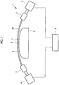
Fig. 1 is a schematic configuration diagram showing a stretch forming device according to a first embodiment of the present invention. -
Fig. 2 is a schematic configuration diagram showing the stretch forming device according to the first embodiment of the present invention. -
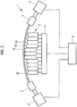
Fig. 3 is a schematic configuration diagram showing a stretch forming device according to a second embodiment of the present invention. -
Fig. 4 is a schematic configuration diagram showing the stretch forming device according to the second embodiment of the present invention. -
Fig. 5 is a schematic configuration diagram showing a modification example of the stretch forming device according to the second embodiment of the present invention. -
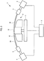
Fig. 6 is a schematic configuration diagram showing a stretch forming device according to a third embodiment of the present invention. - Hereinafter, embodiments of the present invention will be described with reference to the drawings.
- Hereinafter, a first embodiment of the present invention will be described using
Figs. 1 and2 . - A stretch forming device 1 according to this embodiment is a device that performs stretch forming on an
elongate material 20 that is a material to be formed, by using adie 2. Theelongate material 20 is made of, for example, an aluminum alloy and is a material which is manufactured as a structural member such as a frame or a stringer which configures an aircraft component such as a fuselage or a main wing of an aircraft. - The
elongate material 20 is a material (W material obtained by performing roll-forming on an annealed (anneal) material (0 material) and performing solution treatment on the 0 material obtained by the roll-forming. Alternatively, theelongate material 20 may be a material obtained by performing roll-forming on a W material obtained by performing solution treatment on an annealed material (O material). - In stretch forming, gripping
parts 3 respectively grip both end portions of theelongate material 20, and theelongate material 20 is pressed against the die 2 (or thedie 2 is pressed against the elongate material 20) while causing a tensile force to act on theelongate material 20. Then, in the stretch forming, plastic deformation is performed on theelongate material 20 formed into a curved shape by roll-forming, thereby further giving a curved shape to theelongate material 20. - The stretch forming device 1 includes the
die 2, thegripping part 3, a movingunit 4, anoperation unit 5, and the like. - The die 2 has a forming
surface 6 which is long along a longitudinal direction of theelongate material 20 that is a material to be formed. The formingsurface 6 of thedie 2 is formed so as to give a curved shape to theelongate material 20 and has a curved surface. The cross-sectional shape of thedie 2 is a curved shape in which the center side of the formingsurface 6 bulges, and is a part of a circular arc or an ellipse, for example. - The gripping
part 3 is configured to grip an end portion of theelongate material 20. The grippingparts 3 are respectively installed at both end portions of theelongate material 20. Thegripping part 3 is connected to the movingunit 4 and can be moved by themoving unit 4. - A
second die 7 is removably installed at the central portion of the formingsurface 6 of thedie 2 according to this embodiment. Thesecond die 7 has a second formingsurface 8 in which the length thereof along the longitudinal direction of theelongate material 20 is shorter than the length of the formingsurface 6 and which is along the formingsurface 6. The second formingsurface 8 has, for example, a curved surface parallel to the formingsurface 6 of thedie 2. The length of thesecond die 7 is in a range of about 1/4 to 1/3 of the length of the die 2. - The moving
units 4 move thegripping parts 3 to move theelongate material 20 gripped by thegripping parts 3 to the formingsurface 6 side of thedie 2, and in a case where thesecond die 7 is not installed, themoving units 4 move thegripping parts 3 to press theelongate material 20 against the formingsurface 6 of thedie 2, or in a case where thesecond die 7 is installed, themoving units 4 move thegripping parts 3 to press theelongate material 20 against for the second formingsurface 8 of thesecond die 7. Further, the movingunits 4 move thegripping parts 3 to the outside in the longitudinal direction of theelongate material 20 to apply a tensile force to theelongate material 20 pressed against the formingsurface 6 of thedie 2 or the second formingsurface 8 of thesecond die 7. - The
operation unit 5 receives an input operation from a worker and transmits an operation signal to the movingunits 4. - In the above description, the
moving units 4 move thegripping parts 3 to move theelongate material 20 gripped by the grippingparts 3 to the formingsurface 6 side of thedie 2. However, the present invention is not limited thereto and the die 2 may be moved to theelongate material 20 side by a moving unit (not shown) that moves thedie 2. - In a stretch forming method using the stretch forming device 1 according to this embodiment, first, as shown in
Fig. 1 , thesecond die 7 is installed on the formingsurface 6 of thedie 2. Then, theelongate material 20 gripped by thegripping parts 3 is moved, so that theelongate material 20 is pressed against the second formingsurface 8 of thesecond die 7. Further, the movingunits 4 move thegripping parts 3 to the outside in the longitudinal direction of theelongate material 20, thereby applying a tensile force to theelongate material 20 pressed against the second formingsurface 8 of the second die 7 (a first mode). At this time, theelongate material 20 is prevented from coming into contact with the formingsurface 6 of thedie 2. - In this way, the contact area between the
elongate material 20 and thesecond die 7 becomes smaller than the contact area between theelongate material 20 and thedie 2 when thesecond die 7 is not installed, and therefore, when a tensile force is applied to theelongate material 20, a frictional force which acts on the vicinity of the central portion of theelongate material 20 is reduced, and thus the tensile force which is transmitted to the vicinity of the central portion increases. As a result, the amount of deformation which is generated in the vicinity of the central portion of theelongate material 20 increases. - Next, in a case where, based on the amount of movement in a tensile direction detected at the moving
unit 4, it was confirmed that a predetermined amount of deformation was given, the movement of the movingunit 4 is stopped and the application of the tensile force to theelongate material 20 is stopped. Then, theelongate material 20 gripped by thegripping parts 3 is moved, so that theelongate material 20 is separated from the second formingsurface 8, and thesecond die 7 is removed from the formingsurface 6. - Thereafter, the
elongate material 20 gripped by thegripping parts 3 is moved, so that theelongate material 20 is pressed against the formingsurface 6 of thedie 2, as shown inFig. 2 . Further, the movingunits 4 move thegripping parts 3 to the outside in the longitudinal direction of theelongate material 20, thereby applying a tensile force to theelongate material 20 pressed against the formingsurface 6 of the die 2 (a second mode). Next, in a case where, based on the amount of movement in the tensile direction detected at the movingunit 4, it was confirmed that a predetermined amount of deformation was given, the movement of the movingunit 4 is stopped and the application of the tensile force to theelongate material 20 is stopped. Then, theelongate material 20 gripped by thegripping parts 3 is moved, so that theelongate material 20 is separated from the formingsurface 6. - In this way, the
elongate material 20 is plastically deformed along the formingsurface 6 of thedie 2, so that a curved shape is given to theelongate material 20. - In the related art, from the time of the start of stretch forming, the
elongate material 20 is pressed against the formingsurface 6 of thedie 2 to give a curved shape to theelongate material 20. However, in this embodiment, first, theelongate material 20 is pressed against the second formingsurface 8 of thesecond die 7 having a small contact area to reduce a frictional force which acts on the vicinity of the central portion of theelongate material 20 and increase the tensile force which is transmitted to the vicinity of the central portion, thereby increasing the amount of deformation which is generated in the vicinity of the central portion of theelongate material 20. Then, the stretch forming is performed again on theelongate material 20 to which a large amount of deformation is given compared to the related art, by thedie 2. - The stretch forming is carried out in two steps in this manner, whereby it is possible to reduce residual stress in the vicinity of the central portion of the
elongate material 20. As a result, it is possible to reduce a shape change which occurs when etching or cutting work such as drilling is performed after the stretch forming, or variation for each material after cutting work. Further, since the existingdie 2 can be utilized, it is not necessary to newly manufacture a die. - Next, a second embodiment of the present invention will be described using
Figs. 3 and4 . With respect to the same configurations and operation as those in the first embodiment, a detailed description thereof will be omitted. - Unlike the first embodiment, the
die 2 according to this embodiment has a plurality of divided dies 10. That is, thedie 2 is divided into a plurality of pieces in the longitudinal direction of theelongate material 20 which is a material to be formed. Then, the plurality of divided dies 10 can be individually changed in position with respect to theelongate material 20. - The contact portion with the
elongate material 20 in each of the divided dies 10 has a curved surface, as shown inFigs. 3 and4 . - In this embodiment, a moving
unit 11 which moves the divided dies 10 is further provided. By changing the position of each of the divided dies 10 by the movingunit 11, it is also possible to dispose each divided die 10 (first mode), as shown inFig. 3 . That is, like a state where thesecond die 7 is installed on the formingsurface 6 of thedie 2 of the first embodiment, the divided dies 10 installed at the central portion, among the plurality of divided dies 10, can be disposed to protrude to theelongate material 20 side more than the divided dies 10 disposed at end portions. The length of the central portion in which the divided dies 10 protrude is in a range of about 1/4 to 1/3 of the entire length of thedie 2. - Further, by changing the position of each of the divided dies 10 by the moving
unit 11, it is possible to dispose the plurality of divided dies 10 in a curved shape in which the center side bulges (a second mode), as shown inFig. 4 . In this way, the plurality of divided dies 10 can give a curved shape to theelongate material 20, like the formingsurface 6 of thedie 2 of the first embodiment. - By adjusting the disposition position of each of the divided dies 10 by the moving
unit 11, switching between the first mode and the second mode is possible. The switching between the first mode and the second mode may be performed manually by a worker, or may be performed by a control device so as to shift from the first mode to the second mode when, by detection of the amount of deformation of theelongate material 20, it was confirmed that a predetermined amount of deformation was given. - As shown in
Figs. 3 and4 , the divided dies 10 may be divided into two or more divided dies at each of the central portion and the end portion to form a finely curved shape, or as shown inFig. 5 , the divided dies 10 may include a total of three divided dies, one at the central portion and one at each of the end portions. Further, a combination of both the aspects is also possible. - In a stretch forming method using the stretch forming device 1 according to this embodiment, first, as shown in
Fig. 3 , the divided dies 10 installed at the central portion, among the plurality of divided dies 10, are disposed to protrude to theelongate material 20 side more than the divided dies 10 disposed at the end portions. Then, theelongate material 20 gripped by thegripping parts 3 is moved, so that theelongate material 20 is pressed against the divided dies 10 disposed to protrude at the central portion. Further, the movingunits 4 move thegripping parts 3 to the outside in the longitudinal direction of theelongate material 20, thereby applying a tensile force to theelongate material 20 pressed against the divided dies 10 (a first mode). At this time, theelongate material 20 is prevented from coming into contact with the divided dies 10 disposed at the end portions. - In this" way, the contact area between the
elongate material 20 and the divided dies 10 becomes smaller than the contact area between theelongate material 20 and thedie 2 when being pressed against all the divided dies 10, and therefore, when a tensile force is applied to theelongate material 20, a frictional force which acts on the vicinity of the central portion of theelongate material 20 is reduced, and thus the tensile force which is transmitted to the vicinity of the central portion increases. As a result, the amount of deformation which is generated in the vicinity of the central portion of theelongate material 20 is increased. - Next, in a case where, based on the amount of movement in the tensile direction detected at the moving
unit 4, it was confirmed that a predetermined amount of deformation was given, the movement of the movingunit 4 is stopped and the application of the tensile force to theelongate material 20 is stopped. Then, each divided die 10 is moved, and thus the plurality of divided dies 10 are disposed in a curved shape in which the center side bulges, so as to be able to give a curved shape to the elongate material 20 (refer toFig. 4 ). - Thereafter, the moving
units 4 move thegripping parts 3 again to the outside in the longitudinal direction of theelongate material 20, thereby applying a tensile force to theelongate material 20 pressed against the divided dies 10 (a second mode). Next, in a case where, based on the amount of movement in the tensile direction detected at the movingunit 4, it was confirmed that a predetermined amount of deformation was given, the movement of the movingunit 4 is stopped and the application of the tensile force to theelongate material 20 is stopped. Then, theelongate material 20 gripped by thegripping parts 3 is moved, so that theelongate material 20 is separated from the divided dies 10. - In this way, the
elongate material 20 is plastically deformed along the plurality of divided dies 10 of thedie 2, so that a curved shape is given to theelongate material 20. - In the related art, from the time of the start of stretch forming, the
elongate material 20 is pressed against all the plurality of divided dies 10 to give a curved shape to theelongate material 20. However, in this embodiment, first, theelongate material 20 is pressed against only the divided dies 10 of the central portion such that a contact area is reduced, and thus a frictional force which acts on the vicinity of the central portion of theelongate material 20 is reduced, and thus the tensile force which is transmitted to the vicinity of the central portion increases, whereby the amount of deformation which is generated in the vicinity of the central portion of theelongate material 20 is increased. Then, the stretch forming is performed again on theelongate material 20 to which a large amount of deformation is given, compared to the related art, by thedie 2. - The stretch forming is performed in two steps in this manner, whereby it is possible to reduce residual stress in the vicinity of the central portion of the
elongate material 20. As a result, it is possible to reduce a shape change which occurs when etching or cutting work such as drilling is performed after the stretch forming, or variation for each material after cutting work. Further, unlike the first embodiment, a time which is taken to remove thesecond die 7 is not required, and a change of a die shape can be automatically carried out by a machine, not a manual operation. - Next, a third embodiment of the present invention will be described using
Fig. 6 . With respect to the same configurations and operation as those in the first embodiment, a detailed description thereof will be omitted. - In this embodiment, unlike the first embodiment, the stretch forming is carried out in two steps using only the
die 2 without installing thesecond die 7 on the formingsurface 6 of thedie 2. That is, the stretch forming is performed on theelongate material 20 in two steps, similar to the first and second embodiments, by adjusting a moving direction of thegripping part 3 by the movingunit 4 to press theelongate material 20 against only the central portion of the formingsurface 6, as shown by a solid line portion of theelongate material 20 inFig. 6 , or to press theelongate material 20 over the entire surface in the longitudinal direction of the formingsurface 6, as shown by a two-dot chain line portion of theelongate material 20 inFig. 6 . - The moving
units 4 move thegripping parts 3 to move theelongate material 20 gripped by thegripping parts 3 to the formingsurface 6 side of thedie 2 and press theelongate material 20 against the formingsurface 6 of thedie 2. Further, the movingunits 4 move thegripping parts 3 to the outside in the longitudinal direction of theelongate material 20 to apply a tensile force to theelongate material 20 pressed against the formingsurface 6 of thedie 2. - In a first mode, the moving
units 4 move thegripping parts 3 such that only the central portion of the formingsurface 6 of thedie 2 presses theelongate material 20 while applying a tensile force to theelongate material 20 by moving thegripping parts 3. In a second mode, the movingunits 4 move thegripping parts 3 such that the entire surface of the formingsurface 6 of thedie 2 presses theelongate material 20 while applying a tensile force to theelongate material 20 by thegripping parts 3. In the first mode, the length of the central portion of the formingsurface 6, with which theelongate material 20 is brought into contact, is in a range of about 1/4 to 1/3 of the entire length of the formingsurface 6. - By adjusting the moving direction of the
gripping part 3 by the movingunit 4, switching between the first mode and the second mode is possible. The switching between the first mode and the second mode may be performed manually by a worker, or may be performed by a control device to shift from the first mode to the second mode when, by detection of the amount of deformation of theelongate material 20, it was confirmed that a predetermined amount of deformation was given. - In a stretch forming method using the stretch forming device 1 according to this embodiment, first, as shown by the solid line portion of the
elongate material 20 inFig. 6 , theelongate material 20 gripped by thegripping parts 3 is moved such that only the central portion of the formingsurface 6 of thedie 2 presses theelongate material 20, and thus theelongate material 20 is pressed against the central portion of the formingsurface 6 of thedie 2. Further, the movingunits 4 move thegripping parts 3 to the outside in the longitudinal direction of theelongate material 20, thereby applying a tensile force to theelongate material 20 pressed against the central portion of the formingsurface 6 of the die 2 (the first mode). At this time, theelongate material 20 is prevented from coming into contact with the end portions other than the central portion of the formingsurface 6 of thedie 2. - In this way, the contact area between the
elongate material 20 and thedie 2 becomes smaller than the contact area when theelongate material 20 and the entire surface of thedie 2 come into contact with each other, and therefore, when a tensile force is applied to theelongate material 20, a frictional force which acts on the vicinity of the central portion of theelongate material 20 is reduced, and thus the tensile force which is transmitted to the vicinity of the central portion increases. As a result, the amount of deformation which is generated in the vicinity of the central portion of theelongate material 20 increases. - Next, in a case where, based on the amount of movement in the tensile direction detected at the moving
unit 4, it was confirmed that a predetermined amount of deformation was given, the movement of the movingunit 4 is stopped and the application of the tensile force to theelongate material 20 is stopped. - Thereafter, the moving
units 4 are moved while thegripping parts 3 grip theelongate material 20, and thus theelongate material 20 is pressed against the entire surface of the formingsurface 6 of thedie 2, as shown by the two-dot chain line portion of theelongate material 20 inFig. 6 . Further, the movingunits 4 move thegripping parts 3 to the outside in the longitudinal direction of theelongate material 20, thereby applying a tensile force to theelongate material 20 pressed against the entire surface of the formingsurface 6 of the die 2 (the second mode). Next, in a case where, based on the amount of movement in the tensile direction detected at the movingunit 4, it was confirmed that a predetermined amount of deformation was given, the movement of the movingunit 4 is stopped and the application of the tensile force to theelongate material 20 is stopped. Then, theelongate material 20 gripped by thegripping parts 3 is moved, so that theelongate material 20 is separated from the formingsurface 6. - In this way, the
elongate material 20 is plastically deformed along the entire surface of the formingsurface 6 of thedie 2, so that a curved shape is given to theelongate material 20. - In the related art, from the time of the start of stretch forming, the
elongate material 20 is pressed against the entire surface of the formingsurface 6 of thedie 2 to give a curved shape to theelongate material 20. However, in this embodiment, first, theelongate material 20 is pressed against only the central portion of the formingsurface 6 of thedie 2 having a small contact area, whereby a frictional force which acts on the vicinity of the central portion of theelongate material 20 is reduced, and thus the tensile force which is transmitted to the vicinity of the central portion is increased, thereby increasing the amount of deformation which is generated in the vicinity of the central portion of theelongate material 20. Then, the stretch forming is performed again on theelongate material 20 to which a large amount of deformation is given compared to the related art, by the entire surface of the formingsurface 6 of thedie 2. - The stretch forming is performed in two steps in this manner, whereby it is possible to reduce residual stress in the vicinity of the central portion of the
elongate material 20. As a result, it is possible to reduce a shape change which occurs when etching or cutting work such as drilling is performed after the stretch forming, or variation for each material after cutting work. Further, since the existingdie 2 can be utilized, it is not necessary to newly manufacture a die. -
- 1: stretch forming device
- 2: die
- 3: gripping part
- 4: moving unit
- 5: operation unit
- 6: forming surface
- 7: second die
- 8: second forming surface
- 10: divided die
- 11: moving unit
- 20: elongate material
Claims (6)
- A stretch forming device comprising:a die; andgripping parts which grip both end portions of a material to be formed having an elongated shape,wherein a cross-sectional shape of the die has a curved shape in which a center side of a forming surface of the die bulges, and the forming surface is formed so as to give a curved shape to the material to be formed,a second die having a second forming surface in which a length thereof along a longitudinal direction of the material to be formed is shorter than a length of the forming surface and which is along the forming surface is removably installed at a central portion of the forming surface, andthe stretch forming device hasa first mode in which, when the second die has been installed on the forming surface, only the second die presses the material to be formed while a tensile force is applied to the material to be formed by the gripping parts, anda second mode in which, when the second die has been removed from the forming surface, the die presses the material to be formed while a tensile force is applied to the material to be formed by the gripping parts.
- A stretch forming device comprising:a die; andgripping parts which grip both end portions of a material to be formed having an elongated shape,wherein the die is divided into a plurality of pieces in a longitudinal direction of a material to be formed to have a plurality of divided dies which can be individually changed in position with respect to a side of the material to be formed, andthe stretch forming device hasa first mode in which, when the divided die installed at a central portion, among the plurality of divided dies, is disposed to protrude to the side of the material to be formed more than the divided dies installed at end portions, only the divided die disposed at the central portion presses the material to be formed while a tensile force is applied to the material to be formed by the gripping parts, anda second mode in which, when the plurality of divided dies disposed at the central portion and the end portions are disposed so as to give a curved shape to the material to be formed, the plurality of divided dies disposed at the central portion and the end portions press the material to be formed while a tensile force is applied to the material to be formed by the gripping parts.
- A stretch forming device comprising:a die; andgripping parts which grip both end portions of a material to be formed having an elongated shape,wherein a cross-sectional shape of the die has a curved shape in which a center side of a forming surface of the die bulges, and the forming surface is formed so as to give a curved shape to the material to be formed, andthe stretch forming device hasa first mode in which only a central portion of the forming surface of the die presses the material to be formed while a tensile force is applied to the material to be formed by the gripping parts, anda second mode in which an entire surface of the forming surface of the die presses the material to be formed while a tensile force is applied to the material to be formed by the gripping parts.
- A stretch forming method using a stretch forming device,
the device including
a die, and
gripping parts which grip both end portions of a material to be formed having an elongated shape,
a cross-sectional shape of the die having a curved shape in which a center side of a forming surface of the die bulges, and the forming surface being formed so as to give a curved shape to the material to be formed,
the method comprising:a step of installing a second die having a second forming surface in which a length thereof along a longitudinal direction of the material to be formed is shorter than a length of the forming surface and which is along the forming surface, at a central portion of the forming surface;a step of causing, when the second die has been installed on the forming surface, only the second die to press the material to be formed while a tensile force is applied to the material to be formed by the gripping parts; anda step of causing, when the second die has been removed from the forming surface, the die to press the material to be formed while a tensile force is applied to the material to be formed by the gripping parts. - A stretch forming method using a stretch forming device,
the device including
a die, and
gripping parts which grip both end portions of a material to be formed having an elongated shape,
the die being divided into a plurality of pieces in a longitudinal direction of a material to be formed to have a plurality of divided dies which can be individually changed in position with respect to a side of the material to be formed,
the method comprising:a step of disposing the divided die installed at a central portion, among the plurality of divided dies, so as to protrude to the side of the material to be formed more than the divided dies installed at end portions;a step of causing only the divided die disposed at the central portion to press the material to be formed while a tensile force is applied to the material to be formed by the gripping parts; anda step of causing, when the plurality of divided dies disposed at the central portion and the end portions are disposed so as to give a curved shape to the material to be formed, the plurality of divided dies disposed at the central portion and the end portions to press the material to be formed while a tensile force is applied to the material to be formed by the gripping parts. - A stretch forming method using a stretch forming device,
the device including
a die, and
gripping parts which grip both end portions of a material to be formed having an elongated shape,
a cross-sectional shape of the die having a curved shape in which a center side of a forming surface of the die bulges, and the forming surface being formed so as to give a curved shape to the material to be formed,
the method comprising:a step of causing only a central portion of the forming surface of the die to press the material to be formed while a tensile force is applied to the material to be formed by the gripping parts; anda step of causing an entire surface of the forming surface of the die to press the material to be formed while a tensile force is applied to the material to be formed by the gripping parts.
Applications Claiming Priority (1)
| Application Number | Priority Date | Filing Date | Title |
|---|---|---|---|
| PCT/JP2017/035357 WO2019064462A1 (en) | 2017-09-28 | 2017-09-28 | Stretch forming device and stretch forming method |
Publications (2)
| Publication Number | Publication Date |
|---|---|
| EP3586989A1 true EP3586989A1 (en) | 2020-01-01 |
| EP3586989A4 EP3586989A4 (en) | 2020-04-22 |
Family
ID=65901117
Family Applications (1)
| Application Number | Title | Priority Date | Filing Date |
|---|---|---|---|
| EP17927131.7A Withdrawn EP3586989A4 (en) | 2017-09-28 | 2017-09-28 | Stretch forming device and stretch forming method |
Country Status (4)
| Country | Link |
|---|---|
| US (1) | US20200108431A1 (en) |
| EP (1) | EP3586989A4 (en) |
| JP (1) | JP6834014B2 (en) |
| WO (1) | WO2019064462A1 (en) |
Families Citing this family (3)
| Publication number | Priority date | Publication date | Assignee | Title |
|---|---|---|---|---|
| CN114101472B (en) * | 2021-11-30 | 2023-04-21 | 内蒙古工业大学 | Aluminum alloy creep aging forming equipment |
| JP7765964B2 (en) * | 2021-12-24 | 2025-11-07 | 住友重機械工業株式会社 | Stretch molding device and stretch molding method |
| JP2024143169A (en) * | 2023-03-30 | 2024-10-11 | 三菱重工業株式会社 | Stretch molding method and stretch molding device |
Family Cites Families (11)
| Publication number | Priority date | Publication date | Assignee | Title |
|---|---|---|---|---|
| US4548065A (en) * | 1983-05-27 | 1985-10-22 | Rockwell International Corporation | Stretch-forming tool |
| JPH01154821A (en) * | 1987-12-10 | 1989-06-16 | Maru Kikai Kogyo Kk | Bending die for press brake |
| US5860314A (en) * | 1996-10-02 | 1999-01-19 | Powers, Iii; John | Stretch bend forming apparatus, method and product formed thereby |
| US6053026A (en) * | 1998-10-07 | 2000-04-25 | Northrop Grumman Corporation | Block-set form die assembly |
| JP2001137972A (en) * | 1999-11-12 | 2001-05-22 | Mitsubishi Heavy Ind Ltd | Universal forming die |
| US6272897B1 (en) * | 2000-02-25 | 2001-08-14 | Anthony D. Ciranna | Method of forming honeycomb panels into compound curved shapes |
| JP4679752B2 (en) * | 2001-04-23 | 2011-04-27 | 日本飛行機株式会社 | Mold unit and mold device |
| JP2006231380A (en) * | 2005-02-25 | 2006-09-07 | Mitsubishi Heavy Ind Ltd | Flexible stretch die and stretch forming apparatus using the same |
| CN101389420A (en) * | 2006-01-25 | 2009-03-18 | 联邦科学技术研究组织 | Actively reconfigurable stretch forming |
| KR101034593B1 (en) * | 2008-05-30 | 2011-05-12 | 부산대학교 산학협력단 | Stretch plate forming apparatus including a plurality of forming punch and stretching plate forming method using the same |
| JP5961088B2 (en) * | 2012-10-16 | 2016-08-02 | 川崎重工業株式会社 | Stretch forming system and stretch forming method |
-
2017
- 2017-09-28 EP EP17927131.7A patent/EP3586989A4/en not_active Withdrawn
- 2017-09-28 WO PCT/JP2017/035357 patent/WO2019064462A1/en not_active Ceased
- 2017-09-28 JP JP2019545517A patent/JP6834014B2/en active Active
- 2017-09-28 US US16/496,774 patent/US20200108431A1/en not_active Abandoned
Also Published As
| Publication number | Publication date |
|---|---|
| JPWO2019064462A1 (en) | 2019-12-19 |
| EP3586989A4 (en) | 2020-04-22 |
| JP6834014B2 (en) | 2021-02-24 |
| US20200108431A1 (en) | 2020-04-09 |
| WO2019064462A1 (en) | 2019-04-04 |
Similar Documents
| Publication | Publication Date | Title |
|---|---|---|
| US20200108431A1 (en) | Stretch forming device and stretch forming method | |
| KR102307443B1 (en) | Bending machine and corresponding method | |
| US10836125B2 (en) | Pultrusion of continuous sections having discontinuous cross-sectional profile | |
| JP6752545B2 (en) | Method for determining peeling parameters for stripping cables | |
| CN105006723B (en) | Method and apparatus for establishing crimping connection | |
| DE102015101715B4 (en) | Method and forming device for producing a hollow body | |
| SE1150251A1 (en) | Method of cold forming a sheet metal by bending or pressing molding | |
| KR101210889B1 (en) | Severe plastic deformation system and method for working wire rod using the same | |
| EP3112041B1 (en) | Press-forming method and press-forming device | |
| US12070783B2 (en) | Method and apparatus for axially shaping a tube | |
| CN110177633B (en) | Part of surface-treated steel sheet having cut end face and method for producing the same | |
| US20170282468A1 (en) | Pulling Device for a Pultrusion Device | |
| JP2024143169A (en) | Stretch molding method and stretch molding device | |
| US12479018B2 (en) | Workpiece processing method and processing device | |
| DE102015217015B3 (en) | Method and device for producing a sheet metal blank by means of laser cutting | |
| CN103629219B (en) | There is the axle collar of wall of variable thickness | |
| JP4988916B2 (en) | Hot rolled strip winding method and winding apparatus | |
| DE102015219757A1 (en) | Method for connecting at least two components by means of a punch riveting device | |
| RU2682736C2 (en) | Method of forming metal sheet and formed part | |
| JP2006205195A (en) | Roll forging method and roll forging equipment | |
| EP3229989B1 (en) | A method and arrangement for manufacturing of tubes by continuous hydraulic expansion | |
| KR102255626B1 (en) | Shear processing method, shear processing equipment and shear processing equipment | |
| WO2015074840A1 (en) | Blind rivet, setting method, and setting tool | |
| EP3623070A1 (en) | Electromagnetic forming device | |
| KR20160104037A (en) | Method for fastening an element to a pin |
Legal Events
| Date | Code | Title | Description |
|---|---|---|---|
| STAA | Information on the status of an ep patent application or granted ep patent |
Free format text: STATUS: THE INTERNATIONAL PUBLICATION HAS BEEN MADE |
|
| PUAI | Public reference made under article 153(3) epc to a published international application that has entered the european phase |
Free format text: ORIGINAL CODE: 0009012 |
|
| STAA | Information on the status of an ep patent application or granted ep patent |
Free format text: STATUS: REQUEST FOR EXAMINATION WAS MADE |
|
| 17P | Request for examination filed |
Effective date: 20190925 |
|
| AK | Designated contracting states |
Kind code of ref document: A1 Designated state(s): AL AT BE BG CH CY CZ DE DK EE ES FI FR GB GR HR HU IE IS IT LI LT LU LV MC MK MT NL NO PL PT RO RS SE SI SK SM TR |
|
| AX | Request for extension of the european patent |
Extension state: BA ME |
|
| A4 | Supplementary search report drawn up and despatched |
Effective date: 20200323 |
|
| RIC1 | Information provided on ipc code assigned before grant |
Ipc: B21D 53/92 20060101ALI20200317BHEP Ipc: B21D 37/08 20060101ALI20200317BHEP Ipc: B21D 25/02 20060101AFI20200317BHEP Ipc: B21D 31/00 20060101ALI20200317BHEP Ipc: B21D 11/02 20060101ALN20200317BHEP Ipc: B21D 37/02 20060101ALI20200317BHEP |
|
| DAV | Request for validation of the european patent (deleted) | ||
| DAX | Request for extension of the european patent (deleted) | ||
| STAA | Information on the status of an ep patent application or granted ep patent |
Free format text: STATUS: EXAMINATION IS IN PROGRESS |
|
| 17Q | First examination report despatched |
Effective date: 20210215 |
|
| STAA | Information on the status of an ep patent application or granted ep patent |
Free format text: STATUS: THE APPLICATION HAS BEEN WITHDRAWN |
|
| 18W | Application withdrawn |
Effective date: 20210409 |