EP3586972A1 - Zentrifugalabscheider - Google Patents
Zentrifugalabscheider Download PDFInfo
- Publication number
- EP3586972A1 EP3586972A1 EP18179557.6A EP18179557A EP3586972A1 EP 3586972 A1 EP3586972 A1 EP 3586972A1 EP 18179557 A EP18179557 A EP 18179557A EP 3586972 A1 EP3586972 A1 EP 3586972A1
- Authority
- EP
- European Patent Office
- Prior art keywords
- outlet channel
- centrifugal separator
- separator according
- outlet
- liquid
- Prior art date
- Legal status (The legal status is an assumption and is not a legal conclusion. Google has not performed a legal analysis and makes no representation as to the accuracy of the status listed.)
- Granted
Links
Images
Classifications
-
- B—PERFORMING OPERATIONS; TRANSPORTING
- B04—CENTRIFUGAL APPARATUS OR MACHINES FOR CARRYING-OUT PHYSICAL OR CHEMICAL PROCESSES
- B04B—CENTRIFUGES
- B04B11/00—Feeding, charging, or discharging bowls
- B04B11/08—Skimmers or scrapers for discharging ; Regulating thereof
- B04B11/082—Skimmers for discharging liquid
-
- B—PERFORMING OPERATIONS; TRANSPORTING
- B04—CENTRIFUGAL APPARATUS OR MACHINES FOR CARRYING-OUT PHYSICAL OR CHEMICAL PROCESSES
- B04B—CENTRIFUGES
- B04B1/00—Centrifuges with rotary bowls provided with solid jackets for separating predominantly liquid mixtures with or without solid particles
- B04B1/20—Centrifuges with rotary bowls provided with solid jackets for separating predominantly liquid mixtures with or without solid particles discharging solid particles from the bowl by a conveying screw coaxial with the bowl axis and rotating relatively to the bowl
- B04B2001/2083—Configuration of liquid outlets
Definitions
- the present invention relates to centrifugal separators having a device for the transformation of kinetic energy of a liquid rotating in an outlet chamber around a rotational axis to pressure energy.
- This device comprises an element for the discharge of liquid out of said outlet chamber, which element has a radially outer part shaped as a body of revolution about the rotational axis and arranged to be located in a rotating liquid body in said outlet chamber, at least one outlet channel formed in the element and having an inlet opening located in a surface of the body of revolution and elongated in the liquid flow direction, the inlet opening connecting to the interior of an outlet tube via said outlet channel.
- centrifugal separator which provided with an energy transformation device of the above form, parts of the rotor of the centrifugal separator form an outlet chamber, in which the liquid rotates.
- the outlet chamber is arranged to receive a separated liquid continuously from the separation chamber of the centrifugal rotor. This liquid forms a rotating liquid body in the outlet chamber.
- an outlet device is arranged, through which liquid is discharged out of the outlet chamber and further out of the centrifugal rotor.
- a centrifugal separator of this kind is shown in EP 0404923 , for instance.
- the object of the present invention is to provide a centrifugal separator having a device of the kind initially described for the transformation of kinetic energy of a rotating liquid to pressure energy, which device can recover a greater part of the static and the dynamic pressure in the rotating liquid than previously known such devices without involving an increasing risk for the admixture of air in the liquid, and with minimal pressure loss at said change from horizontal, radial to axial flow direction.
- a centrifugal separator having a device for the transformation of kinetic energy of a liquid rotating in a chamber around a rotational axis to pressure energy, comprising an element for the discharge of liquid out of the chamber, which element has a radially outer part shaped as a body of revolution about the rotational axis and arranged to be located in the rotating liquid body, at least one outlet channel formed in the element and having an inlet opening located in a surface of the body of revolution and elongated in the liquid flow direction, the inlet opening connecting to the interior of an outlet tube via said outlet channel, wherein said outlet channel having a defined axial height (h) and a defined width (w) and wherein a defined aspect ratio h/w being larger than 1 in an outer first part of said outlet channel and decreasing to smaller than 1 in an inner second part of said outlet channel and wherein the axial height (h) decreases inwardly along the length of said outlet channel
- the cross-sectional area of the outlet channel is constant or increases along the outlet channel in the direction of flow therethrough.
- the h/w is set larger >1 at entrance, preferable in the interval 1.5 to 2.
- the flow path change direction from horizontal, mainly radial to mainly axial at the connection between paring disc and the axial outlet channel.
- the radial extension of the axial channel ( ⁇ R) is for number of practical reasons kept small.
- ⁇ R radial extension of the axial channel
- h is reduced along flow path in the horizontal, radial part of the channel, while w is gradually increased in such rate that the channel cross section area is constant or gradually increasing. This allows to make the curvature of the bend from horizontal, radial to axial larger as measured relative channel heights or ⁇ R. This reduces pressure loss at bend horizontal, radial to axial.
- One execution is to extend the diffusor to the axial part of the channel.
- Said aspect ratio may decrease from between 1.25-2.00 to 0.25-0.75.
- Said aspect ratio may decrease from between 1.50-2.00 to 0.40-0.60.
- Said decrease may be in an inner second part of said outlet channel, wherein said inner second part is attached to the said outlet tube.
- the inner second part of the outlet channel attaches to the outlet tube by a bend directed upwards with a radius R 1 .
- the height (h) of the outlet channel may decrease by an upper wall of outlet channel which is sloping inwardly along the length of said outlet channel.
- Said element may have 2 to 8 outlet channels.
- Said element may have 4 to 7 outlet channels.
- the cross-sectional area of the outlet channel may gradually increase along the outlet channel in the direction of flow therethrough.
- Said cross section of the outlet channel may be substantially rectangular.
- Said inlet opening may be formed in an essentially radially facing surface of the element.
- the inlet opening may be of one of the following shapes: triangular, NACA duct profile or rectangular shape.
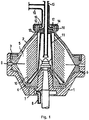
- a centrifugal separator shown in fig 1 comprises a rotor having a lower part 1 and an upper part 2 joined together axially by means of a locking ring 3 or in another suitable manner.
- This valve slide 4 delimits together with the upper part 2 a separation chamber 5 and is arranged to open and close an annular gap towards the outlet openings 6 for a component, which during operation is separated out of a mixture supplied to the rotor and is collected at the periphery of the separation chamber 5.
- the valve slide 4 delimits together with the lower part 1 a closing chamber 7, which is provided with an inlet 8 and a throttled outlet 9 for a closing liquid.
- a stationary inlet tube 15 extends axially, which delivers fluid to be separated into the separation chamber.
- a stationary coaxial outlet tube 16 for the specific lighter liquid component collected in the chamber 12.
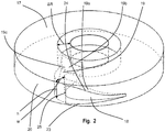
- the discharge element 17 extends radially outwards and has outside the radial level of the free liquid surface 14 of the rotating liquid body a part, which has at least one inlet opening 18.
- This inlet opening 18 is connected to the interior of the outlet tube 16 via an outlet channel 19 formed in the discharge element 17.
- the inlet opening 18 can be of a triangular, NACA duct profile, rectangular or other shape.
- the h/w is set larger >1 at entrance, preferable in the interval 1.5 to 2.
- the flow path change direction from horizontal, mainly radial to mainly axial at the connection between paring disc and the axial outlet channel.
- the radial extension of the axial channel ( ⁇ R) is for number of practical reasons kept small.
- ⁇ R radial extension of the axial channel
- h is reduced along flow path in the horizontal, radial part of the channel, while w is gradually increased in such rate that the channel cross section area is constant or gradually increasing. This allows to make the curvature of the bend from horizontal, radial to axial larger as measured relative channel heights or ⁇ R. This reduces pressure loss at bend horizontal, radial to axial.
- Said discharge element 17 may have one outlet channel 19 as is disclosed in fig. 2 but may instead have 2 to 8 outlet channels, preferably 4 to 7 outlet channels 19.
- the cross-sectional area of the outlet channel 19 may be chosen to gradually increase along the outlet channel 19 in the direction of flow therethrough.
- the cross section of the outlet channel 19 may be substantially rectangular. Other cross section configurations may be possible like triangular, multi-angled or other shapes.
- the discharge element 17 may consist of a circular cylindrical disc.
- the inlet opening 18 may have triangular, NACA duct profile or rectangular shape but other shapes may be possible.
- Said inlet opening 18 is formed in an essentially radially facing surface of the discharge element 17.
- the discharge chamber 12 is formed in a part of a rotary body 2 but embodiments where the discharge chamber 12 is formed in a stationary part is possible.
- inlet openings are formed in a circular cylindrical surface and facing radially.
- the invention is also applicable to devices having inlet openings which face in another direction, for instance axially.
Landscapes
- Centrifugal Separators (AREA)
Priority Applications (5)
| Application Number | Priority Date | Filing Date | Title |
|---|---|---|---|
| EP18179557.6A EP3586972B1 (de) | 2018-06-25 | 2018-06-25 | Zentrifugalabscheider |
| PCT/EP2019/065387 WO2020001981A1 (en) | 2018-06-25 | 2019-06-12 | Centrifugal separator |
| CN201980042494.0A CN112292210B (zh) | 2018-06-25 | 2019-06-12 | 离心分离器 |
| CA3104007A CA3104007C (en) | 2018-06-25 | 2019-06-12 | Centrifugal separator |
| US17/251,267 US11213831B2 (en) | 2018-06-25 | 2019-06-12 | Centrifugal separator having an outlet channel of varying height |
Applications Claiming Priority (1)
| Application Number | Priority Date | Filing Date | Title |
|---|---|---|---|
| EP18179557.6A EP3586972B1 (de) | 2018-06-25 | 2018-06-25 | Zentrifugalabscheider |
Publications (2)
| Publication Number | Publication Date |
|---|---|
| EP3586972A1 true EP3586972A1 (de) | 2020-01-01 |
| EP3586972B1 EP3586972B1 (de) | 2020-12-02 |
Family
ID=62778788
Family Applications (1)
| Application Number | Title | Priority Date | Filing Date |
|---|---|---|---|
| EP18179557.6A Active EP3586972B1 (de) | 2018-06-25 | 2018-06-25 | Zentrifugalabscheider |
Country Status (5)
| Country | Link |
|---|---|
| US (1) | US11213831B2 (de) |
| EP (1) | EP3586972B1 (de) |
| CN (1) | CN112292210B (de) |
| CA (1) | CA3104007C (de) |
| WO (1) | WO2020001981A1 (de) |
Citations (2)
| Publication number | Priority date | Publication date | Assignee | Title |
|---|---|---|---|---|
| EP0404923A1 (de) | 1989-01-13 | 1991-01-02 | Alfa Laval Separation Ab | Trennschleuder mit einer vorrichtung zur umwandlung von kinetischer energie in druck. |
| DE10143405A1 (de) * | 2001-09-05 | 2003-04-03 | Westfalia Separator Food Tec G | Schälscheibenvorrichtung zum Ableiten von Flüssigkeit aus einer Zentrifugentrommel |
Family Cites Families (10)
| Publication number | Priority date | Publication date | Assignee | Title |
|---|---|---|---|---|
| US2125453A (en) * | 1934-06-30 | 1938-08-02 | Laval Separater Company De | Antifroth discharging means for centrifugal separators |
| US2171136A (en) | 1934-09-01 | 1939-08-29 | Laval Separator Co De | Centrifugal separator provided with special discharges |
| US2230210A (en) | 1937-01-02 | 1941-01-28 | Laval Separator Co De | Process and apparatus for saturating fruit juices and other liquids with gas |
| SE8901254D0 (sv) | 1989-04-07 | 1989-04-07 | Alfa Laval Separation Ab | Energiomvandlingsanordning |
| US6602180B2 (en) | 2000-04-04 | 2003-08-05 | Fleetguard, Inc. | Self-driven centrifuge with vane module |
| SE530690C2 (sv) | 2006-04-04 | 2008-08-12 | Alfa Laval Corp Ab | Rotorenhet för en centrifugalseparator |
| SE536019C2 (sv) | 2009-11-06 | 2013-04-02 | Alfa Laval Corp Ab | Hermetisk centrifugalseparator |
| DE102010038195A1 (de) | 2010-10-14 | 2012-04-19 | Gea Mechanical Equipment Gmbh | Verfahren zur Phasentrennung eines Produktes mit einer Zentrifuge |
| DE102012106648A1 (de) | 2012-07-23 | 2014-01-23 | Gea Mechanical Equipment Gmbh | Separatoranordnung |
| EP2796203B1 (de) | 2013-04-23 | 2015-11-25 | Andritz Frautech S.r.l. | Vorrichtung zum Abziehen von Flüssigkeit aus einer Zentrifugiervorrichtung |
-
2018
- 2018-06-25 EP EP18179557.6A patent/EP3586972B1/de active Active
-
2019
- 2019-06-12 CA CA3104007A patent/CA3104007C/en active Active
- 2019-06-12 WO PCT/EP2019/065387 patent/WO2020001981A1/en not_active Ceased
- 2019-06-12 US US17/251,267 patent/US11213831B2/en not_active Expired - Fee Related
- 2019-06-12 CN CN201980042494.0A patent/CN112292210B/zh active Active
Patent Citations (2)
| Publication number | Priority date | Publication date | Assignee | Title |
|---|---|---|---|---|
| EP0404923A1 (de) | 1989-01-13 | 1991-01-02 | Alfa Laval Separation Ab | Trennschleuder mit einer vorrichtung zur umwandlung von kinetischer energie in druck. |
| DE10143405A1 (de) * | 2001-09-05 | 2003-04-03 | Westfalia Separator Food Tec G | Schälscheibenvorrichtung zum Ableiten von Flüssigkeit aus einer Zentrifugentrommel |
Also Published As
| Publication number | Publication date |
|---|---|
| US11213831B2 (en) | 2022-01-04 |
| EP3586972B1 (de) | 2020-12-02 |
| CN112292210B (zh) | 2022-06-03 |
| CN112292210A (zh) | 2021-01-29 |
| CA3104007A1 (en) | 2020-01-02 |
| WO2020001981A1 (en) | 2020-01-02 |
| US20210245176A1 (en) | 2021-08-12 |
| CA3104007C (en) | 2021-12-07 |
Similar Documents
| Publication | Publication Date | Title |
|---|---|---|
| US11660607B2 (en) | Separation disc for a centrifugal separator | |
| US9737835B2 (en) | Methods and apparatuses for separating liquid particles from a gas-liquid stream | |
| WO1995029013A1 (en) | Centrifugal separator | |
| US11117143B2 (en) | Centrifugal filtration device | |
| US11007542B2 (en) | Cyclone separator and methods of using same | |
| EP2628544B1 (de) | Zentrifugaltrenner mit Einlassanordnung | |
| WO2002034406A1 (en) | Pump vanes for a decanter centrifuge feed chamber | |
| EP3586972B1 (de) | Zentrifugalabscheider | |
| EP0404923B1 (de) | Trennschleuder mit einer vorrichtung zur umwandlung von kinetischer energie in druck | |
| EP0699107B1 (de) | Verfahren zur regelung des abflusses einer in einem zentrifugalabscheider abgeschiedenen flüssigkeit sowie zentrifugalabscheider zur durchführung des verfahrens | |
| AU2004200362B2 (en) | Separating cyclone and method for separating a mixture | |
| US5518494A (en) | Centrifugal separator with air entrainment suppression | |
| EP0419635B1 (de) | Zentrifugal-abschleudervorrichtung mit energieumwandlung | |
| JP6561120B2 (ja) | 最適化された配管ユニットによって連結されている2つのサイクロンを具備するサイクロン式分離装置 | |
| CN108722027B (zh) | 惯性分离装置及其集液器 | |
| MXPA04012096A (es) | Un dispositivo para un depurador ciclonico. | |
| EP1058585B1 (de) | Zentrifugalabscheider | |
| JPS63283771A (ja) | 複数相混合物の遠心分離方法および装置 | |
| WO1988002664A1 (en) | Centrifugal separator having a stationary discharge member | |
| EP0616557A1 (de) | Trennzentrifuge | |
| SE434977B (sv) | Anordning for okning av stromningshastigheten i ett vetske- eller gasformigt medium |
Legal Events
| Date | Code | Title | Description |
|---|---|---|---|
| PUAI | Public reference made under article 153(3) epc to a published international application that has entered the european phase |
Free format text: ORIGINAL CODE: 0009012 |
|
| STAA | Information on the status of an ep patent application or granted ep patent |
Free format text: STATUS: REQUEST FOR EXAMINATION WAS MADE |
|
| 17P | Request for examination filed |
Effective date: 20180625 |
|
| AK | Designated contracting states |
Kind code of ref document: A1 Designated state(s): AL AT BE BG CH CY CZ DE DK EE ES FI FR GB GR HR HU IE IS IT LI LT LU LV MC MK MT NL NO PL PT RO RS SE SI SK SM TR |
|
| AX | Request for extension of the european patent |
Extension state: BA ME |
|
| GRAP | Despatch of communication of intention to grant a patent |
Free format text: ORIGINAL CODE: EPIDOSNIGR1 |
|
| STAA | Information on the status of an ep patent application or granted ep patent |
Free format text: STATUS: GRANT OF PATENT IS INTENDED |
|
| INTG | Intention to grant announced |
Effective date: 20200814 |
|
| RAP1 | Party data changed (applicant data changed or rights of an application transferred) |
Owner name: ALFA LAVAL CORPORATE AB |
|
| GRAS | Grant fee paid |
Free format text: ORIGINAL CODE: EPIDOSNIGR3 |
|
| GRAA | (expected) grant |
Free format text: ORIGINAL CODE: 0009210 |
|
| STAA | Information on the status of an ep patent application or granted ep patent |
Free format text: STATUS: THE PATENT HAS BEEN GRANTED |
|
| AK | Designated contracting states |
Kind code of ref document: B1 Designated state(s): AL AT BE BG CH CY CZ DE DK EE ES FI FR GB GR HR HU IE IS IT LI LT LU LV MC MK MT NL NO PL PT RO RS SE SI SK SM TR |
|
| REG | Reference to a national code |
Ref country code: GB Ref legal event code: FG4D |
|
| REG | Reference to a national code |
Ref country code: AT Ref legal event code: REF Ref document number: 1340308 Country of ref document: AT Kind code of ref document: T Effective date: 20201215 Ref country code: CH Ref legal event code: EP |
|
| REG | Reference to a national code |
Ref country code: IE Ref legal event code: FG4D |
|
| REG | Reference to a national code |
Ref country code: DE Ref legal event code: R096 Ref document number: 602018010280 Country of ref document: DE |
|
| PG25 | Lapsed in a contracting state [announced via postgrant information from national office to epo] |
Ref country code: FI Free format text: LAPSE BECAUSE OF FAILURE TO SUBMIT A TRANSLATION OF THE DESCRIPTION OR TO PAY THE FEE WITHIN THE PRESCRIBED TIME-LIMIT Effective date: 20201202 Ref country code: RS Free format text: LAPSE BECAUSE OF FAILURE TO SUBMIT A TRANSLATION OF THE DESCRIPTION OR TO PAY THE FEE WITHIN THE PRESCRIBED TIME-LIMIT Effective date: 20201202 Ref country code: NO Free format text: LAPSE BECAUSE OF FAILURE TO SUBMIT A TRANSLATION OF THE DESCRIPTION OR TO PAY THE FEE WITHIN THE PRESCRIBED TIME-LIMIT Effective date: 20210302 Ref country code: GR Free format text: LAPSE BECAUSE OF FAILURE TO SUBMIT A TRANSLATION OF THE DESCRIPTION OR TO PAY THE FEE WITHIN THE PRESCRIBED TIME-LIMIT Effective date: 20210303 |
|
| REG | Reference to a national code |
Ref country code: NL Ref legal event code: MP Effective date: 20201202 |
|
| REG | Reference to a national code |
Ref country code: AT Ref legal event code: MK05 Ref document number: 1340308 Country of ref document: AT Kind code of ref document: T Effective date: 20201202 |
|
| PG25 | Lapsed in a contracting state [announced via postgrant information from national office to epo] |
Ref country code: BG Free format text: LAPSE BECAUSE OF FAILURE TO SUBMIT A TRANSLATION OF THE DESCRIPTION OR TO PAY THE FEE WITHIN THE PRESCRIBED TIME-LIMIT Effective date: 20210302 Ref country code: LV Free format text: LAPSE BECAUSE OF FAILURE TO SUBMIT A TRANSLATION OF THE DESCRIPTION OR TO PAY THE FEE WITHIN THE PRESCRIBED TIME-LIMIT Effective date: 20201202 Ref country code: PL Free format text: LAPSE BECAUSE OF FAILURE TO SUBMIT A TRANSLATION OF THE DESCRIPTION OR TO PAY THE FEE WITHIN THE PRESCRIBED TIME-LIMIT Effective date: 20201202 Ref country code: SE Free format text: LAPSE BECAUSE OF FAILURE TO SUBMIT A TRANSLATION OF THE DESCRIPTION OR TO PAY THE FEE WITHIN THE PRESCRIBED TIME-LIMIT Effective date: 20201202 |
|
| PG25 | Lapsed in a contracting state [announced via postgrant information from national office to epo] |
Ref country code: HR Free format text: LAPSE BECAUSE OF FAILURE TO SUBMIT A TRANSLATION OF THE DESCRIPTION OR TO PAY THE FEE WITHIN THE PRESCRIBED TIME-LIMIT Effective date: 20201202 Ref country code: NL Free format text: LAPSE BECAUSE OF FAILURE TO SUBMIT A TRANSLATION OF THE DESCRIPTION OR TO PAY THE FEE WITHIN THE PRESCRIBED TIME-LIMIT Effective date: 20201202 |
|
| REG | Reference to a national code |
Ref country code: LT Ref legal event code: MG9D |
|
| PG25 | Lapsed in a contracting state [announced via postgrant information from national office to epo] |
Ref country code: LT Free format text: LAPSE BECAUSE OF FAILURE TO SUBMIT A TRANSLATION OF THE DESCRIPTION OR TO PAY THE FEE WITHIN THE PRESCRIBED TIME-LIMIT Effective date: 20201202 Ref country code: PT Free format text: LAPSE BECAUSE OF FAILURE TO SUBMIT A TRANSLATION OF THE DESCRIPTION OR TO PAY THE FEE WITHIN THE PRESCRIBED TIME-LIMIT Effective date: 20210405 Ref country code: SK Free format text: LAPSE BECAUSE OF FAILURE TO SUBMIT A TRANSLATION OF THE DESCRIPTION OR TO PAY THE FEE WITHIN THE PRESCRIBED TIME-LIMIT Effective date: 20201202 Ref country code: RO Free format text: LAPSE BECAUSE OF FAILURE TO SUBMIT A TRANSLATION OF THE DESCRIPTION OR TO PAY THE FEE WITHIN THE PRESCRIBED TIME-LIMIT Effective date: 20201202 Ref country code: SM Free format text: LAPSE BECAUSE OF FAILURE TO SUBMIT A TRANSLATION OF THE DESCRIPTION OR TO PAY THE FEE WITHIN THE PRESCRIBED TIME-LIMIT Effective date: 20201202 Ref country code: CZ Free format text: LAPSE BECAUSE OF FAILURE TO SUBMIT A TRANSLATION OF THE DESCRIPTION OR TO PAY THE FEE WITHIN THE PRESCRIBED TIME-LIMIT Effective date: 20201202 Ref country code: EE Free format text: LAPSE BECAUSE OF FAILURE TO SUBMIT A TRANSLATION OF THE DESCRIPTION OR TO PAY THE FEE WITHIN THE PRESCRIBED TIME-LIMIT Effective date: 20201202 |
|
| PG25 | Lapsed in a contracting state [announced via postgrant information from national office to epo] |
Ref country code: AT Free format text: LAPSE BECAUSE OF FAILURE TO SUBMIT A TRANSLATION OF THE DESCRIPTION OR TO PAY THE FEE WITHIN THE PRESCRIBED TIME-LIMIT Effective date: 20201202 |
|
| REG | Reference to a national code |
Ref country code: DE Ref legal event code: R097 Ref document number: 602018010280 Country of ref document: DE |
|
| PG25 | Lapsed in a contracting state [announced via postgrant information from national office to epo] |
Ref country code: IS Free format text: LAPSE BECAUSE OF FAILURE TO SUBMIT A TRANSLATION OF THE DESCRIPTION OR TO PAY THE FEE WITHIN THE PRESCRIBED TIME-LIMIT Effective date: 20210402 |
|
| PLBE | No opposition filed within time limit |
Free format text: ORIGINAL CODE: 0009261 |
|
| STAA | Information on the status of an ep patent application or granted ep patent |
Free format text: STATUS: NO OPPOSITION FILED WITHIN TIME LIMIT |
|
| PG25 | Lapsed in a contracting state [announced via postgrant information from national office to epo] |
Ref country code: IT Free format text: LAPSE BECAUSE OF FAILURE TO SUBMIT A TRANSLATION OF THE DESCRIPTION OR TO PAY THE FEE WITHIN THE PRESCRIBED TIME-LIMIT Effective date: 20201202 Ref country code: AL Free format text: LAPSE BECAUSE OF FAILURE TO SUBMIT A TRANSLATION OF THE DESCRIPTION OR TO PAY THE FEE WITHIN THE PRESCRIBED TIME-LIMIT Effective date: 20201202 |
|
| 26N | No opposition filed |
Effective date: 20210903 |
|
| PG25 | Lapsed in a contracting state [announced via postgrant information from national office to epo] |
Ref country code: DK Free format text: LAPSE BECAUSE OF FAILURE TO SUBMIT A TRANSLATION OF THE DESCRIPTION OR TO PAY THE FEE WITHIN THE PRESCRIBED TIME-LIMIT Effective date: 20201202 Ref country code: SI Free format text: LAPSE BECAUSE OF FAILURE TO SUBMIT A TRANSLATION OF THE DESCRIPTION OR TO PAY THE FEE WITHIN THE PRESCRIBED TIME-LIMIT Effective date: 20201202 |
|
| PG25 | Lapsed in a contracting state [announced via postgrant information from national office to epo] |
Ref country code: MC Free format text: LAPSE BECAUSE OF FAILURE TO SUBMIT A TRANSLATION OF THE DESCRIPTION OR TO PAY THE FEE WITHIN THE PRESCRIBED TIME-LIMIT Effective date: 20201202 Ref country code: ES Free format text: LAPSE BECAUSE OF FAILURE TO SUBMIT A TRANSLATION OF THE DESCRIPTION OR TO PAY THE FEE WITHIN THE PRESCRIBED TIME-LIMIT Effective date: 20201202 |
|
| REG | Reference to a national code |
Ref country code: CH Ref legal event code: PL |
|
| REG | Reference to a national code |
Ref country code: BE Ref legal event code: MM Effective date: 20210630 |
|
| PG25 | Lapsed in a contracting state [announced via postgrant information from national office to epo] |
Ref country code: LU Free format text: LAPSE BECAUSE OF NON-PAYMENT OF DUE FEES Effective date: 20210625 |
|
| PG25 | Lapsed in a contracting state [announced via postgrant information from national office to epo] |
Ref country code: LI Free format text: LAPSE BECAUSE OF NON-PAYMENT OF DUE FEES Effective date: 20210630 Ref country code: IE Free format text: LAPSE BECAUSE OF NON-PAYMENT OF DUE FEES Effective date: 20210625 Ref country code: CH Free format text: LAPSE BECAUSE OF NON-PAYMENT OF DUE FEES Effective date: 20210630 |
|
| PG25 | Lapsed in a contracting state [announced via postgrant information from national office to epo] |
Ref country code: IS Free format text: LAPSE BECAUSE OF FAILURE TO SUBMIT A TRANSLATION OF THE DESCRIPTION OR TO PAY THE FEE WITHIN THE PRESCRIBED TIME-LIMIT Effective date: 20210402 Ref country code: FR Free format text: LAPSE BECAUSE OF NON-PAYMENT OF DUE FEES Effective date: 20210630 |
|
| PG25 | Lapsed in a contracting state [announced via postgrant information from national office to epo] |
Ref country code: BE Free format text: LAPSE BECAUSE OF NON-PAYMENT OF DUE FEES Effective date: 20210630 |
|
| GBPC | Gb: european patent ceased through non-payment of renewal fee |
Effective date: 20220625 |
|
| PG25 | Lapsed in a contracting state [announced via postgrant information from national office to epo] |
Ref country code: GB Free format text: LAPSE BECAUSE OF NON-PAYMENT OF DUE FEES Effective date: 20220625 |
|
| P01 | Opt-out of the competence of the unified patent court (upc) registered |
Effective date: 20230421 |
|
| PG25 | Lapsed in a contracting state [announced via postgrant information from national office to epo] |
Ref country code: CY Free format text: LAPSE BECAUSE OF FAILURE TO SUBMIT A TRANSLATION OF THE DESCRIPTION OR TO PAY THE FEE WITHIN THE PRESCRIBED TIME-LIMIT Effective date: 20201202 |
|
| PG25 | Lapsed in a contracting state [announced via postgrant information from national office to epo] |
Ref country code: HU Free format text: LAPSE BECAUSE OF FAILURE TO SUBMIT A TRANSLATION OF THE DESCRIPTION OR TO PAY THE FEE WITHIN THE PRESCRIBED TIME-LIMIT; INVALID AB INITIO Effective date: 20180625 |
|
| PG25 | Lapsed in a contracting state [announced via postgrant information from national office to epo] |
Ref country code: MK Free format text: LAPSE BECAUSE OF FAILURE TO SUBMIT A TRANSLATION OF THE DESCRIPTION OR TO PAY THE FEE WITHIN THE PRESCRIBED TIME-LIMIT Effective date: 20201202 |
|
| PG25 | Lapsed in a contracting state [announced via postgrant information from national office to epo] |
Ref country code: TR Free format text: LAPSE BECAUSE OF FAILURE TO SUBMIT A TRANSLATION OF THE DESCRIPTION OR TO PAY THE FEE WITHIN THE PRESCRIBED TIME-LIMIT Effective date: 20201202 |
|
| PG25 | Lapsed in a contracting state [announced via postgrant information from national office to epo] |
Ref country code: MT Free format text: LAPSE BECAUSE OF FAILURE TO SUBMIT A TRANSLATION OF THE DESCRIPTION OR TO PAY THE FEE WITHIN THE PRESCRIBED TIME-LIMIT Effective date: 20201202 |
|
| PGFP | Annual fee paid to national office [announced via postgrant information from national office to epo] |
Ref country code: DE Payment date: 20250402 Year of fee payment: 8 |